Embed Size (px)
Citation preview

Linear slide cylinderLCR Series
LINEAR SLIDE CYLINDER LCR SERIES
The height of "light"
CC-996A 1

The Height of "Light"
Increased rigidity from conventional model (LCS)with strengthened slide table and linear guide.Increased rigidity from conventional model (LCS)with strengthened slide table and linear guide.
Up to 10% lighter!!!Compared to conventional models.
Refined RigidityRefined Rigidity
Symmetical structureFit for a variety of applications
Flexible
Stroke length (mm)Bore size
LCR product variation
Series variation
LCR-P7*Double acting single rod type (clean room specifications)
LCRDouble acting single rod type
LCR-QDouble acting position locking type
10
Stopper forstroke adjustment
S*
With buffer
B*
Shock absorber typestopper
A*20 30 40 50 75 100 125 150
Option
Switch
Stopper for adjustable strokeSingle adjusting range 0 to 5mm
Shock absorber type stopperBuffer at stroke limit
Ample options and variationsStandard, position locking and clean room specifications typesare available. Shock absorber type stopper,stopper for adjustable stroke are also available.* Shock absorber type stopper is not available for clean room specification types.
Buffering functionThe buffer protects the cylinder and workpiece whenthe workpiece and drive section crashes. It is used insituations when shock needs to be absorbed on theend of pick and place equipment.Also, switches that detect the activation of the buffer(BL type) can be installed to detect abnormalities.
Buffer mechanismduring operation
Normal
Slidetable
Hand
Workpiece
Piston rod
Magnet
Cylinder switchSpring
Proximity switch with 2 color indicator available.The switch is embedded in the body for a slim design.
Two color switchDesign with freedomSymmetrical stopper, multi-side piping,2 side mounting dowel hole allowsthis to be used in various designs.
shows the piping direction Can be changed symmetrically
Linear slide cylinder
Linear guide
Slide tableSlide table
Linear guide
ø6ø8ø12ø16ø20, ø25
ø6ø8ø12ø16ø20, ø25
ø8ø12ø16ø20, ø25
Displacement of slide table end
Load (N) →25 50
50
LCR0
LCS(conventional product)
Buffer mechanism
Conventional model (LCS)
LCR
Weight has been reduced up to 10%
ApplicationsIdeal for use on Z axis.
LCR
LCG
Contributes to downsizing, shorter tact time and saving energyby reducing the weight of moving parts.
Standard back piping port (not including ø6)
Installation holes on 2 sides
↑
Disp
lacem
ent (
m)

Linear slide cylinderLCR Series
Option
Sw
itch
Pag
e
Stopper for adjustable stroke Shock absorber type stopper With buffer
Variation Model no.
JIS symbol
Bore size
(mm)
Stroke length (mm)
Sto
pper
pos
ition
1
Sto
pper
pos
ition
2
Sto
pper
pos
ition
3
Sto
pper
pos
ition
4
Sto
pper
pos
ition
1
3
Sto
pper
pos
ition
2
4
Sto
pper
pos
ition
1
Sto
pper
pos
ition
2
Sto
pper
pos
ition
3
Sto
pper
pos
ition
4
Sto
pper
pos
ition
1
3
Sto
pper
pos
ition
2
4
With
out s
witc
h gr
oove
With
sw
itch
groo
ve
Plu
g at
tach
ed
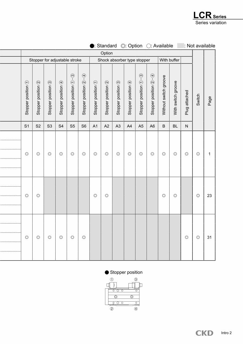
10 20 30 40 50 75 100 125 150 S1 S2 S3 S4 S5 S6 A1 A2 A3 A4 A5 A6 B BL N
Double acting single rod type
ø6
1
LCR ø8
ø12
ø16
ø20, ø25
Double acting position locking type
LCR-Qø8
23ø12
ø16
ø20, ø25
Double acting single rod typeClean room specifications
ø6
31
LCR-P7* ø8
ø12
ø16
ø20, ø25
Intro 1
Series variation
LCR SeriesSeries variation
Option
Sw
itch
Pag
e
Stopper for adjustable stroke Shock absorber type stopper With buffer
Variation Model no.
JIS symbol
Bore size
(mm)
Stroke length (mm)
Sto
pper
pos
ition
1
Sto
pper
pos
ition
2
Sto
pper
pos
ition
3
Sto
pper
pos
ition
4
Sto
pper
pos
ition
1
3
Sto
pper
pos
ition
2
4
Sto
pper
pos
ition
1
Sto
pper
pos
ition
2
Sto
pper
pos
ition
3
Sto
pper
pos
ition
4
Sto
pper
pos
ition
1
3
Sto
pper
pos
ition
2
4
With
out s
witc
h gr
oove
With
sw
itch
groo
ve
Plu
g at
tach
ed
10 20 30 40 50 75 100 125 150 S1 S2 S3 S4 S5 S6 A1 A2 A3 A4 A5 A6 B BL N
Double acting single rod type
ø6
1
LCR ø8
ø12
ø16
ø20, ø25
Double acting position locking type
LCR-Qø8
23ø12
ø16
ø20, ø25
Double acting single rod typeClean room specifications
ø6
31
LCR-P7* ø8
ø12
ø16
ø20, ø25
: Standard : Option : Available : Not available
Intro 2
2 4
1 3
Stopper position

Intro 3
Safety precautionsAlways read this section before starting use.
When designing and manufacturing a device using CKD products, the manufacturer is obligated to check that device safety and mechanism, pneumatic or hydraulic control circuit and the system operated by electrical control that controls the devices is secured.It is important to select, use, handle, and maintain the product appropriately to ensure that the CKD product is used safely.Observe warnings and precautions to ensure device safety.Check that device safety is ensured, and manufacture a safe device.
1 This product is designed and manufactured as a general industrial machine part.It must be handled by an operator having sufficient knowledge and experience in handling.
2 Use this product in accordance of specifications.This product must be used within its stated specifications. It must not be modified or machined.This product is intended for use as a general-purpose industrial device or part. It is not intended for use outdoors or for use under the following conditions or environment.(However, if CKD is consulted prior to use and the customer consents to CKD product specifications, then the product may be used under conditions not intended. In that case, the customer must provide safety measures to avoid risks in the event of failures.))1 Use for special applications including nuclear energy, railway, aircraft, marine vessel, vehicle, medical devices, devices coming into contact with
beverages or foodstuffs, amusement devices, emergency cutoff circuits (cutoff, open, etc.), press machines, press circuits, or safety devices.2 Use for applications where life or assets could be adversely affected, and special safety measures are required.
3 Observe corporate standards, regulations and etc., related to the safety of device design and control, etc.ISO4414, JIS B8370 (pneumatic system rules)JFPS2008 (principles for pneumatic cylinder selection and use)Including High Pressure Gas Maintenance Law, Occupational Safety and Sanitation Laws, other safety rules, body standards and regulations, etc.
4 Do not handle, pipe, or remove devices before confirming safety.1 Do not inspect or service equipment/machinery until safety is confirmed on the entire systems related to this product.2 Note that there may be hot or charged sections even after operation is stopped.3 When inspecting or servicing the device, turn off the energy source (air supply or water supply), and turn off power to the
facility. Discharge any compressed air from the system, and pay maximum attention to possible leakage of water and electricity4 When starting or restarting a machine or device that incorporates pneumatic components, make sure that the
system safety, such as pop-out prevention measures, is secured.5 Observe warnings and cautions on the pages below to prevent accidents.
WARNING
The precautions are ranked as "DANGER", "WARNING" and "CAUTION" in this section.
DANGER: When a dangerous situation may occur if handling is mistaken leading to fatal or serious injuries, or when there is a high degree of emergency to a warning.
WARNING: When a dangerous situation may occur if handling is mistaken leading to fatal or serious injuries.
CAUTION: When a dangerous situation may occur if handling is mistaken leading to minor injuries or physical damage.
Note that some items described as “CAUTION” may lead to serious results depending on the situation.In any case, important information that must be observed is explained.
Limited warranty and disclaimer
1 Term of warranty"Warranty Period" is one (1) year from the first delivery to the customer.
2 Scope of warrantyIn case any defect attributable to CKD is found during the term of warrantyThis limited warranty will not apply to:(1) Product abuse/misuse contrary to conditions/environment recommended in its catalogs/specifications.(2) Failure due to other causes.(3) Use other than original design purposes.(4) Third-party repair/modification(5) Failure due to causes not foreseeable with technology at the time of delivery.(6) Failure attributable to force majeure.In no event shall CKD be liable for business interruptions, loss of profits, personal injury, costs of delay or for any other special, indirect, incidental or consequential losses costs or damages.
3 Compatibility confirmationIn no event shall CKD be liable for merchantability or fitness for a particular purpose, notwithstanding any disclosure to CKD of the use to which the product is to be put.

Pneumatic components
Safety precautionsAlways read this section before starting use.Refer to Pneumatic Cylinders I (CB-029SA) for further details on cylinder switches and cylinders in general.
CAUTION Select the cylinder according to the "LCR selection guide" on pages 47 to 50.
When using the cylinder where it could be subject to water or oil exposure, where it could corrode, or where high levels of dust are present, the cylinder could malfunction or get damaged. Protect the product with a cover.
Cautions of type with switch If the T*V type switch is used with the stopper for stroke adjustment (S3**, S4**, S5**, S6**) or shock absorber type stopper (A3**, A4**, A5**, A6**), the switch on the head interferes with the stopper. Install the switch on the opposite side of the stopper.
1. Common
CAUTION Do not use a 3-position valve.Do not use this cylinder combined with 3-position valve, especially that with a closed center metal seal. The lock is not applied if pressure is sealed on the port having the lock. Even if locked once, air leakage from the valve may enter the cylinder then the lock may be released over time.
2. Position locking type LCR-Q
Design & Selection
CAUTION When changing the piping position, use adhesive on M3 and M5 plugs (hexagon socket head set screw). Use a low-strength adhesive such as LOCTITE 222/221, or ThreeBond 1344.
Piping port position and operating direction
1. Common; piping
Installation & Adjustment
DescriptionsPort size
Port dimension
AApplicable joints Joint outer diameter
BBore size (mm)
ø6 M3 4
SC3W-M3-4
ø8or less
SC3U-M3-4SC3W-M3-3.2SC3U-M3-3.2GWS3-M3-SGWS4-M3-S
ø8
M5
5.5 SC3W-M5-4ø11
or lessSC3W-M5-6
ø12 5.5 GWS4-M5-SGWS4-M5
ø16 6.5
SC3W-M5-4
ø13or less
SC3W-M5-6GWS4-M5-SGWS4-M5GWL4-M5GWL6-M5GWS6-M5
ø20
Rc1/8
8SC3W-6-4, 6, 8
ø15or less
GWS4-6GWS8-6
ø25 9GWL6-6GWS6-6GWL4-6
When using a switch with a stroke of less than 30, one switch is installed in each of the two grooves on the body. Check the direction of leads in design.
Precautions for piping jointInstall a speed control valve when piping. The applicable joints are shown as below.
R indicates the rod end, H indicates the head end pressurizing port. When shipped from the factory, the ports other than R1 and H1 are sealed with plugs. This may be R2 and H2 depending on the stopper position if a stopper is selected.
If the T*V type switch is used with the stopper for stroke adjustment (S3**, S4**, S5**, S6**) or shock absorber type stopper (A3**, A4**, A5**, A6**), the switch on the head interferes with the stopper. Install the switch on the opposite side of the stopper.
Rear piping This product can be used with rear piping (port R3 , H3 on figure above) except for ø6 and position locking models. When using this product, remove the plug sealing R3 and H3 , and seal ports R1 and H1 shown on the table to the right.
Descriptions PlugLCR-6 Port R3 and H3 do not exist.LCR-8
M5 x 5 (hexagon socket head set screw)LCR-12LCR-16LCR-20 R1/8 (hexagon socket head tapered screw plug)
LCR-25 Seal ports R3 and H3 with plugs used to seal ports R1 and H1 .
2 more plugs are required separately from the chart above when using ø8 to 20.Use the plug attachment options on page 3 and plug model number on page 6 as a reference.
Intro 4
øB
A
R1 H1
R2 H2
H3
R3
R3
H3

LCR Series
Installation & Adjustment
DescriptionsTable
Applicable bolts Tightening torque (N m) Screw-in length L (mm)LCR-6 M3 x 0.5 0.6 3
LCR-8 M3 x 0.5 0.6 3 to 4.5
LCR-12 M4 x 0.7 1.4 4 to 5.5
LCR-16 M5 x 0.8 2.9 5 to 6
LCR-20 M5 x 0.8 2.9 5 to 6
LCR-25 M6 x 1.0 4.8 6 to 7
Observe the following bolt insertion lengths and tightening torque when installing the jig on the slide table or end plate.<Fig. 2>
Observe the following valves for bolts at the stopper and in nut tightening torque.<Fig. A>
Model1 Stopper mounting bolt 2 Stopper bolt mounting nut 3 Stopper block mounting bolt
2 Shock absorber mounting nut(N m) (N m) (N m)
LCR-6 0.4 to 0.5 1.2 to 2.0 0.6 to 0.8LCR-8 0.4 to 0.5 1.2 to 2.0 0.6 to 0.8
LCR-12 0.6 to 0.8 1.2 to 2.0 0.6 to 0.8LCR-16 0.6 to 0.8 3.0 to 4.0 1.4 to 1.8LCR-20 2.9 to 3.5 4.5 to 6.0 1.4 to 1.8LCR-25 2.9 to 3.5 4.5 to 6.0 2.9 to 3.5
The cylinder switch could malfunction if there is a magnetic substance, such as a steel plate, near the cylinder switch. Mo the magnetic substance to at least 10mm from the cylinder. (Same for all bore size)
Cylinder switch could malfunction if cylinders are placed adjacently. Check that the following distance is maintained between cylinder surfaces. (Same for all bore size)
Shock absorbers are consumables.Replace the shock absorber if energy absorption performance drops or if movement is no longer smooth.
When using the dowel hole, the pin must not have dimensions for press fit. There is a risk of debasement in precision if the linear guide is damaged or deformed by press fit load.Recommended tolerance for the pin is JIS tolerance m6 or less.
DescriptionsEnd plate
Applicable bolts Tightening torque (N m) Screw-in length L (mm)LCR-6 M3 x 0.5 0.6 4.5 to 6
LCR-8 M3 x 0.5 0.6 4.5 to 7
LCR-12 M4 x 0.7 1.4 6 to 9
LCR-16 M5 x 0.8 2.9 7.5 to 9
LCR-20 M5 x 0.8 2.9 7.5 to 11
LCR-25 M6 x 1.0 4.8 9 to 11
CAUTION Check that no dents or scratches occur on main tubing installation or end plates that may adversely affect flatness. The flatness of the counter part onto which the end plate installed must be 0.05mm or less.
Observe the following values for the bolt insertion length and tightening torque when installing this product.<Fig. 1>
2. Common; installation
DescriptionsA B
Applicable bolts Tightening torque (N m) Applicable bolts Tightening torque (N m) Max. screw depth L (mm)LCR-6 M3 x 0.5 0.6 to 1.1 M4 x 0.7 1.4 to 2.4 6
LCR-8 M3 x 0.5 0.6 to 1.1 M4 x 0.7 1.4 to 2.4 6
LCR-12 M4 x 0.7 1.4 to 2.4 M5 x 0.8 2.9 to 5.1 8
LCR-16 M5 x 0.8 2.9 to 5.1 M6 x 1.0 4.8 to 8.6 9
LCR-20 M5 x 0.8 2.9 to 5.1 M6 x 1.0 4.8 to 8.6 9
LCR-25 M6 x 1.0 4.8 to 8.6 M8 x 1.25 12.0 to 21.6 12
Intro 5
L
L
Stopper blockStopper
Stopper bolt
2 Stopper bolt mounting nut
3 Stopper block mounting bolt
1 Stopper mounting bolt
Hexagon socket set screw with rubber cushion
3 Stopper block mounting boltStopper blockStopper
Shock absorber
Shock absorber
1 Stopper mounting bolt2 Shock absorber mounting nut
10mm and over
Magn
etic m
ateria
l suc
h as
stee
l plat
e, etc
.
3mm and over 3mm and over
A B
L

LCR Series
During Use & Maintenance
WARNING If pressure is supplied to port (A) in the locked state with neither port pressurized, locks may not be releasable or may be released suddenly, causing the piston rod to pop out, which is extremely dangerous. When releasing the locking mechanism, supply pressure to port (B) and check that no load is applied to the locking mechanism.
1. Position locking type LCR-Q
If lowering speed is to be increased with the quick exhaust valve, the cylinder may move out faster than the lock pin and prevent the locking pin from being released correctly. Do not use a quick exhaust valve with the cylinder with position locking.
CAUTION If negative pressure is applied to the locking mechanism, the lock may be released. Use the solenoid valve as a discrete unit, or use an independently exhausted manifold.
CAUTION The locking mechanism functions at stroke limit. If the stopper is applied with the external stopper in the middle of a stroke, the locking mechanism will not function and the load may drop. Before setting the load, check that the locking mechanism functions correctly.
Supply a pressure higher than the minimum working pressure to the port with the locking mechanism.
If piping on the side with the lock is thin and long, or if the speed controller is separated from the cylinder port, exhaust may slow, taking time for the lock to function. This may also occur if the silencer on the solenoid valve's exhaust port is clogged.
3. Position locking type LCR-Q
Depending on the speed and load, there is a risk of malfunction of switches. Adjust the speed of this product accordingly to the load. Note that cylinders with buffers cannot be used vertically upward.
4. LCR-B with buffer
Use a buffer below the buffer stroke. There is a risk of damage and malfunction.
Release the lock when installing or adjusting the cylinder.The lock could be damaged if the cylinder is installed while it is locked.
Do not use multiple cylinders in synchronous.Do not move more than one workpiece using more than two cylinders with position locking mechanism in synchronous. One of the cylinder’s locks may not be released.
Use the speed control valve with meter-out control.Lock may not be released during meter-in control.
Use the side with the lock with the cylinder stroke end.If the cylinder’s piston does not reach the stroke end, the lock may not operate.
How to releaseScrew a hexagon socket head bolt (M3 20) into the stopper piston, and pull the bolt up 3 mm with a force of 20N or more. The stopper piston moves and the lock is released during horizontal no-load installation or with the rod port pressurized. When the hand is released, the stopper piston is returned by the internal spring and enters the piston rod slot, locking the cylinder.
After manually operating the locking mechanism, return the locking mechanism to the original position. Do not use a manual override except during adjustment because it is dangerous.
Intro 6
Side without locking mechanism
Port
Port
A
B
W
Hexagon socket head cap boltM3 x 20
Coil spring
Stopper piston
Piston rod groove
When unlockedLocked
3

SpecificationsDescriptions LCR
Bore size mm ø6 ø8 ø12 ø16 ø20 ø25Actuation Double actingWorking fluid Compressed airMax. working pressure MPa 0.7Min. working pressure MPa 0.15 (Note 1)Withstanding pressure MPa 1Ambient temperature °C -10 to 60 (no freezing)
Port sizeBody side surface M3 M5 Rc1/8Rear body M3 M5 Rc1/8
Stroke tolerance mm+ 2.0
(Note 2) 0
Working piston speed mm/s 50 to 500 (Note 3)Cushion Rubber cushionedLubrication Not required (when lubricating, use turbine oil Class 1 ISOVG 32.)Allowable energy absorption J Refer to the table 3 on Page 49.
Stroke length
Note: Stroke length other than above is not available.
Bore size (mm) Standard stroke length (mm)ø6 10, 20, 30, 40, 50ø8 10, 20, 30, 40, 50, 75ø12 10, 20, 30, 40, 50, 75, 100ø16 10, 20, 30, 40, 50, 75, 100, 125ø20 10, 20, 30, 40, 50, 75, 100, 125, 150ø25 10, 20, 30, 40, 50, 75, 100, 125, 150
Linear slide cylinder Double acting single rod type
LCR Series Bore size: ø6 ø8 ø12 ø16 ø20 ø25
Note 1: 0.2MPa when using shock absorber type stopper of ø6.Note 2: When using without a stopper, be careful of the small gap between end plate and floating bush.Note 3: When use the stroke adjustment stopper, use it when it is 50 and 200 mm/s.
Specification with buffer Specifications other than the ones shown below are the same as the specifications shown on the table above.
Descriptions LCR with bufferBore size mm ø6 ø8 ø12 ø16 ø20 ø25Buffer stroke mm 4 9 10BufferSpring load
At setting N 3 5 10 13 17 21During operation N 7 8 14 20 25 29
Note 1: Rod side stroke adjustment by a type with buffer shortens buffer stroke length as much as adjusted stroke length. This also results in higher spring load at setting.
Note 2: Use buffer stroke below the above stroke length. There is a risk of malfunction and damage.
JIS symbol
1

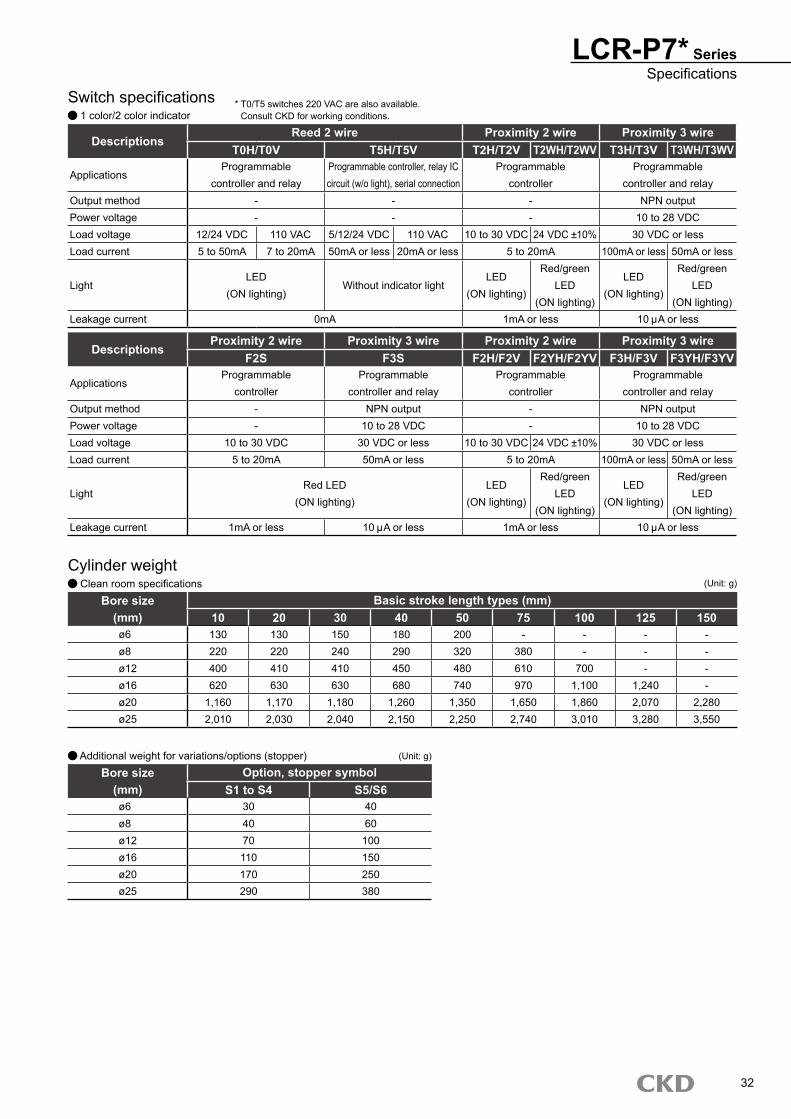
Switch specifications 1 color/2 color indicator
DescriptionsProximity 2 wire Proximity 3 wire Proximity 2 wire Proximity 3 wire
F2S F3S F2H/F2V F2YH/F2YV F3H/F3V F3YH/F3YV
ApplicationsProgrammable
controller dedicatedProgrammable
controller and relayProgrammable
controller dedicatedProgrammable
controller and relayOutput method - NPN output - NPN outputPower voltage - 10 to 28 VDC - 10 to 28 VDCLoad voltage 10 to 30 VDC 30 VDC or less 10 to 30 VDC 24 VDC 10% 30 VDC or lessLoad current 5 to 20mA 50mA or less 5 to 20mA 100mA or less 50mA or less
LightRed LED
(ON lighting)LED
(ON lighting)
Red/greenLED
(ON lighting)
LED(ON lighting)
Red/greenLED
(ON lighting)Leakage current 1mA or less 10 A or less 1mA or less 10 A or less
LCR SeriesSpecifications
Cylinder weight Basic type
Bore size Basic type mm stroke (mm)(mm) 10 20 30 40 50 75 100 125 150ø6 110 110 130 160 180 - - - -ø8 160 160 180 230 260 320 - - -ø12 310 320 320 360 390 520 610 - -ø16 490 500 500 550 610 840 970 1,110 -ø20 900 910 920 1,000 1,090 1,390 1,600 1,810 2,020ø25 1,620 1,640 1,650 1,760 1,860 2,350 2,620 2,890 3,160
(Unit: g)
Additional optionBore size Option, stopper symbol With buffer
(mm) S1 to S4 S5/S6 A1 to A4 A5/A6 B/BLø6 30 40 40 50 40ø8 40 60 50 70 40ø12 70 100 80 110 70ø16 110 150 120 160 80ø20 170 250 180 270 150ø25 290 380 300 400 320
(Unit: g)
DescriptionsReed 2 wire Proximity 2 wire Proximity 3 wire
T0H/T0V T5H/T5V T2H/T2V T2WH/T2WV T3H/T3V T3WH/T3WV
ApplicationsProgrammable
controller and relayProgrammable controller, relay IC circuit (w/o light), serial connection
Programmablecontroller dedicated
Programmablecontroller and relay
Output method - - - NPN outputPower voltage - - - 10 to 28 VDCLoad voltage 12/24 VDC 110 VAC 5/12/24 VDC 110 VAC 10 to 30 VDC 24 VDC 10% 30 VDC or lessLoad current 5 to 50mA 7 to 20mA 50mA or less 20mA or less 5 to 20mA 100mA or less 50mA or less
LightLED
(ON lighting)Without indicator light
LED(ON lighting)
Red/greenLED
(ON lighting)
LED(ON lighting)
Red/greenLED
(ON lighting)Leakage current 0mA 1mA or less 10 A or less
* T0/T5 switches are 220 VAC compatible.Consult CKD for working conditions.
Structure that can be used in secondary battery manufacturing process.P4*LCR-: -
Secondary battery compatible specification
* Consult with CKD for details.
2
E
LCR Series
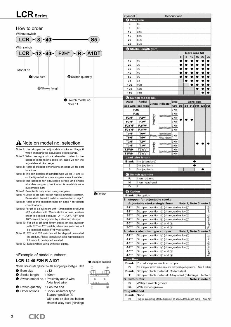
How to orderWithout switch
With switch
Note on model no. selectionNote 1: Use stopper for adjustable stroke on Page 6
when changing the adjustable stroke range.Note 2: When using a shock absorber, refer to the
stopper dimensions table on page 21 for the adjustable stroke range.
Note 3: Refer to stopper dimensions on page 21 for port locations.
Note 4: The port position of standard type will be 1 and 3 on the figure below when stoppers are not installed.
Note 5: The stopper for adjustable stroke and shock absorber stopper combination is available as a customized part.
Note 6: Selectable only when using stoppers.Note 7: Switch for the buffer section must be purchased separately.
Please refer to the switch model no. selection chart on page 5.Note 8: Refer to the selection table on page 4 for option
combinations.Note 9: For ø6 to ø8 cylinders with 10mm stroke or ø12 to
ø25 cylinders with 20mm stroke or less, custom order is applied because A1**, A2**, A5** and A6** can not be adjusted by a standard stopper.
Note 10: For ø6 to ø8 and 30mm stroke or less cylinder with S*** or A*** switch, when two switches will be installed, select F*H type switch.
Note 11: F2S and F3S switches will be shipped uninstalled the product. Please consult our sales representative if it needs to be shipped installed.
Note 12: Select when using with rear piping.
<Example of model number>LCR-12-40-F2H-R-A1DTModel: Linear slide cylinder double acting/single rod type LCRA Bore size : ø12B Stroke length : 40mmC Switch model no. : Proximity and 2 wire Axial lead wireD Switch quantity : 1 on rod endE Other options : Shock absorber type Stopper position 1
With ports on side and bottom Material, alloy steel (nitriding)
LCR S5408
Model no.
Bore sizeA
Stroke lengthB
LCR 4012 F2H* R A1DT
Switch model no.Note 11
C
Switch quantityD
Option
Stopper position
3
Symbol Descriptions Bore size6 ø68 ø8
12 ø1216 ø1620 ø2025 ø25
Stroke length (mm)Bore size (ø)
6 8 12 16 20 2510 1020 2030 3040 4050 5075 75
100 100125 125150 150
Switch model no.Axial
lead wireRadial
lead wireContact Indicator
Lead wire
Bore sizeø6 ø8 ø12 ø16 ø20 ø25
F2S
Prox
imity 1 color indicator
2-wireF3S 3-wire
F2H* F2V* 2-wireF3H* F3V* 3-wire
F2YH* F2YV*2 color indicator
2-wireF3YH* F3YV* 3-wireT0H* T0V*
Reed1 color indicator
2-wireT5H* T5V* Without indicatorT2H* T2V*
Prox
imity 1 color indicator
2-wireT3H* T3V* 3-wire
T2WH* T2WV*2 color indicator
2-wireT3WH* T3WV* 3-wire
* Lead wire lengthBlank 1m (standard)
3 3m (option)5 5m (option)
Switch quantityR 1 on rod endH 1 on head endD 2
OptionBlank No option
S stopper for adjustable strokeAdjustable stroke single 5mm Note 1, Note 5, note 8
S1** Stopper position 1 (changeable to 4 )Sto
pper in
stallat
ion po
sition
S2** Stopper position 2 (changeable to 3 )S3** Stopper position 3 (changeable to 2 )S4** Stopper position 4 (changeable to 1 )S5** Stopper position 1 and 3
S6** Stopper position 2 and 4
A shock absorber type stopper Note 2, Note 5, note 8A1** Stopper position 1 (changeable to 4 )
Stoppe
r insta
llation
positi
on
A2** Stopper position 2 (changeable to 3 )A3** Stopper position 3 (changeable to 2 )A4** Stopper position 4 (changeable to 1 )A5** Stopper position 1 and 3
A6** Stopper position 2 and 4
** sectionBlank Port at stopper section: no port
D Port at stopper section: side surface and bottom side ports presence Note 3, Note 6Blank Stopper block material: Rolled steel
T Stopper block material: Alloy steel (nitriding) Note 6B with buffer Note 7, note 8
B Without switch grooveBL With switch groove
Plug attachedBlank None
N Plug for side piping attached (can not be selected for ø6 and ø25)) Note 12
A
B
C
D
E
1 3
2 4

LCR SeriesHow to order
LCR double acting/single rod type combination availability table(Combinations of stopper for adjustable stroke and shock absorber type stopper)
Model no. symbol Option symbol Stopper for adjustable stroke Shock absorber type stopperBore size Stroke length S1 S2 S3 S4 S5 S6 A1 A2 A3 A4 A5 A6
LCRLCR-B and BL
ø6, ø810 ― ― ― ―
20 and over
ø12 to ø2510 to 20 ― ― ― ―
30 and over
: Combination available -: Combination not available
Combination of option symbol D: With stopper section port and T: Alloy (nitriding) stopper block follows the combination table above.
4

Switch model no.(Page 3 C section)
Switch model no.(Page 3 C section)
LCR Series
How to order switch
For ø6 to ø12 For ø16 to ø25
How to order stopper set Stopper section and stopper for adjustable stroke or shock absorber stopper set Use when changing from standard to “with stopper for adjustable stroke” or “with shock absorber stopper”
SW F2H SW T2H3
Stopper typeS Stopper for adjustable strokeA Shock absorber type stopper
Stopper installation position Note 11 For stopper position 1 or 4
2 For stopper position 2 or 3
Port at stopper sectionBlank No port
D With ports on side and bottom
Adjustable stroke length Note 2 Note 3Blank Adjustable stroke range 5mmS02 Adjustable stroke range 15mmS03 Adjustable stroke range 25mm
ABore size(Page 3 A section)
LCR S12 2 D
B
C
Precautions for ordering stopper set
Only when installing a stopper for adjustable stroke or a shock absorber type stopper on installation position 1 , 2 (refer to page 3), the combination shown on the right may be applied depending on stroke length and adjusted stroke length.
Model no. symbolOption symbol
Discrete stopper for adjustable strokeAdjusted stroke length (mm)
Bore size Stroke length -5 -15 -25
LCR Series
ø6, ø810 S02 ― ―
20 and over Not required additionally S02 ―
ø12 to ø2510 S03 ― ―20 S02 S03 ―
30 and over Not required additionally S02 S03
―: not available
Buffer
Output type2 2 wire proximity DC3 3 wire proximity DC
Radial lead wire
Lead wire lengthBlank 1m (standard)
3 3m (option)
2 V 3FSW
S02
D
Note 1: Refer to the chart below when attaching stopper on 1 or 2 because the stroke adjustment changes according to the stroke.
Note 2: "S03" can not be selected with ø6 or ø8.Note 3: Can not be selected with shock absorber
type stopper "A".
5

LCR SeriesHow to order
How to order the discrete stopper for adjustable stroke Hexagon socket head set screw with urethane Used when changing the adjustable stroke range or setting to custom stroke length.
Adjustable stroke rangeS01 Single 5mm (standard)S02 Single 15mmS03 Single 25mm
ABore size(Page 3 A section)
LCR 12 S02
Cautions when purchasing discrete stopper.
Only when installing a stopper for adjustable stroke or a shock absorber type stopper on installation position 1 , 2 (refer to page 3), the combination shown on the right may be applied depending on stroke length and adjusted stroke length.
Model no. symbolOption symbol
Discrete stopper for adjustable strokeShock absorber type
discrete stopperAdjusted stroke length (mm)
Bore size Stroke length -5 -15 -25
LCR Series-S1, S2, S5, S6-A1, A2, A5, A6
ø6, ø810 S02 ― ― ―
20 and over S01 S02 ― A01
ø12 to ø2510 S03 ― ― ―20 S02 S03 ― ―
30 and over S01 S02 S03 A01
―: combination not available
How to order the discrete shock absorber stopper Sets of shock absorber and stopper cap Use for changing from shock absorber type stopper to stopper for adjustable stroke
Model Shock absorber model no.LCR-6 NCK-00-0.1LCR-8 NCK-00-0.3LCR-12 NCK-00-0.3LCR-16 NCK-00-0.7LCR-20 NCK-00-1.2LCR-25 NCK-00-1.2
Bore size(Page 3 A section)
LCR 12 A01
Discrete stopper block model no. display Used when changing standard type to stopper for adjustable stroke or shock absorber type stopper.
Stopper block
SB1ø6, ø8: 30 mm stroke or lessø12 to ø25: 50 mm stroke or less
SB2ø6, ø8: 40 mm stroke and overø12 to ø25: 75 mm stroke and over
MaterialBlank Stopper block material: Rolled steel
T Stopper block material: Alloy steel (nitriding)
A
Bore size(Page 3 A section)
LCR 12 SB1
Applicable shock absorber model No.
Note: Some models may not be available depending on the type. Refer to Page 3. Refer to page 21 for the stroke adjustment range for the shock absorber type stopper.
T
B
Specify the S01, S02, S03 at the A section.Note: S03 is not available for ø6, ø8.
Depending on model no., some models are not available and adjustable stroke range may be different from above.
Plug kit model no. display for side piping port
Bore size(Page 3 A section)
LCR 12 N (2 piece/1 set)
6
Shock absorber
Stopper cap

LCR Series
Internal structure and parts list LCR
No. Parts name Material Remarks No. Parts name Material Remarks1 Hexagon socket head cap bolt Alloy steel Zinc chromate 16 Guard Aluminum alloy Chromate
2 Floating bush Stainless steel 17 Guard gasket Nitrile rubber
3 C type snap ring Steel For ø8 to 25 only 18 C type snap ring Steel For ø12 to 25 only
4 Rod packing seal Nitrile rubber 19 Hexagon socket head cap bolt Alloy steel Zinc chromate
5 Metal gasket Nitrile rubber 20 End plate Aluminum alloy Alumite
6 Rod bushing Aluminum alloy Alumite 21 Cushion rubber (H) Urethane rubber
7 Piston rod Stainless steel 22 Hexagon socket head set screw Stainless steel
8 Cylinder body Aluminum alloy Hard alumite 23 Table Aluminum alloy Alumite
9 Cushion rubber (R) Urethane rubber24 Plug
Stainless steel ø6 to ø20
10 Piston Aluminum alloy Chromate Steel ø25
11 Piston packing seal Nitrile rubber 25 Hexagon socket head set screw Stainless steel Only ø6
12 Magnet Plastic 26 Rod bushing A Aluminum alloy
13 Plain washer Stainless steel 27 Cap Stainless steel
14 Hexagon nut Stainless steel 28 Hexagon socket set screw Alloy steel Zinc chromate
15 PlugStainless steel ø6 to ø16
Steel ø20 to ø25
Parts list
Bore size (mm) Kit No. Repair parts numberø6 LCR-6K
4 5 9
11 17 21
ø8 LCR-8K
ø12 LCR-12K
ø16 LCR-16K
ø20 LCR-20K
ø25 LCR-25K
Repair parts list
7
●1 ●2 ●3 ●4 ●5 ●6 ●8 ●10 ●12 ●14 ●16
●24
●7 ●9 ●11 ●13 ●15 ●17 ●18
●23●22●21●2019
●28●27●2●26●25●2
When B section is ø6.8When A section is ø8When A section is ø6

LCR SeriesInternal structure and parts list
Internal structure and parts list
Configuration with stopper With port on the side and the bottom (symbol D) Without port on the stopper section
No. Parts name Material Remarks No. Parts name Material Remarks1 Stopper bolt Alloy steel Nickel plated
7
Stopper block(Stopper block symbol: Blank) Steel Nickel plated
2 Hexagon nut Alloy steel Nickel plated
3 Stopper A Aluminum alloy Alumite Stopper block(Stopper block symbol: T) Alloy steel Nitriding
4 Gasket Urethane rubber
5 Hexagon socket head cap bolt Alloy steel Zinc chromate 8 Stopper B Aluminum alloy Alumite
6 Hexagon socket head cap bolt Alloy steel Zinc chromate 9 Stopper bolt Alloy steel Nickel plated
10 Cushion rubber Urethane rubber
Parts list
Structural drawing with buffer
LCR-*-*-B* Without switch groove, with buffer With switch groove, with buffer
Parts listNo. Parts name Material Remarks No. Parts name Material Remarks
1 End plate Aluminum alloy Alumite 6 C type snap ring Steel
2 Hexagon socket head cap bolt Alloy steel Zinc chromate 7 Guard Aluminum alloy Chromate
3 Coil spring Steel 8 Magnet Plastic
4 Stopper ø6: stainless steelø8 to 25: aluminum alloy 9 E ring ø6 to 12: stainless steel
ø16 to 25: steel
5 Cushion rubber Urethane rubber
8
●10
●1 ●2 ●3 ●4 ●5 ●6 ●7 ●8 ●9
6 4 5
7 3 2 19 8
LCR Series
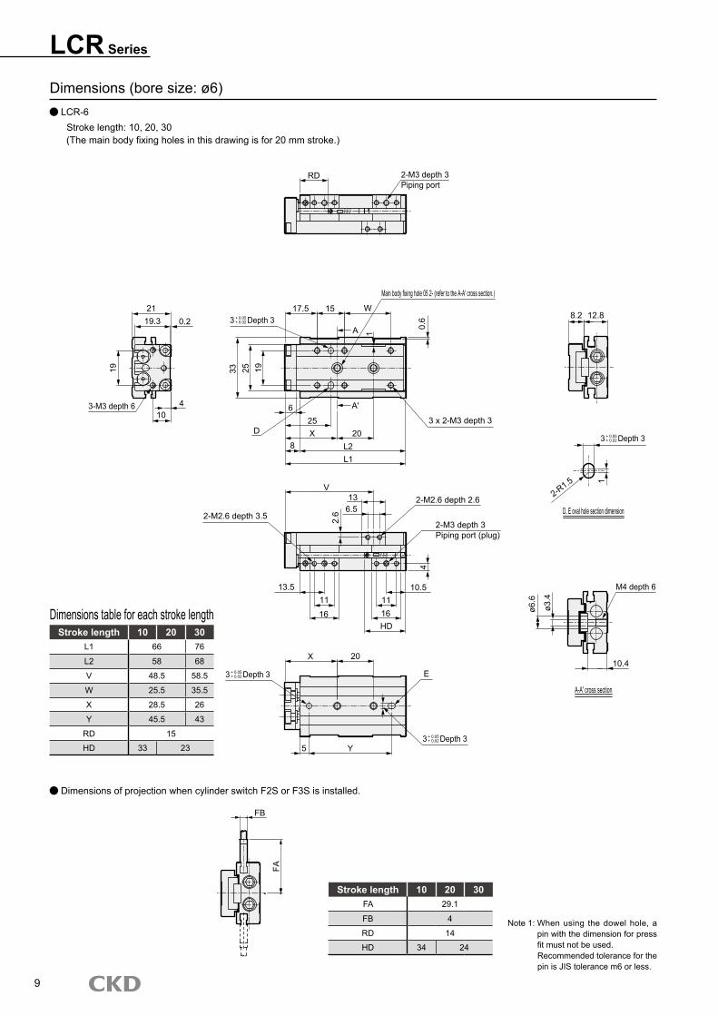
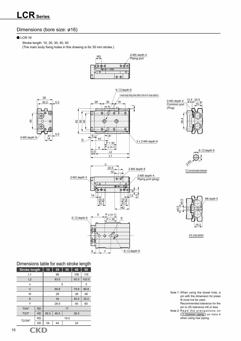
Note 1: When using the dowel hole, a pin with the dimension for press fit must not be used.Recommended tolerance for the pin is JIS tolerance m6 or less.
Dimensions (bore size: ø6) LCR-6
Stroke length: 10, 20, 30(The main body fixing holes in this drawing is for 20 mm stroke.)
Stroke length 10 20 30L1 66 76
L2 58 68
V 48.5 58.5
W 25.5 35.5
X 28.5 26
Y 45.5 43
RD 15
HD 33 23
Dimensions table for each stroke length
Dimensions of projection when cylinder switch F2S or F3S is installed.
Stroke length 10 20 30FA 29.1
FB 4
RD 14
HD 34 24
�
CKDF2H
CKDF2H
RD 2-M3 depth 3Piping port
Main body fixing hole 05 2- (refer to the A-A' cross section.)
17.5 15 W
A 0.6
1
33 25 1�
D3 x 2-M3 depth 3
L1L2
20
A'
8X25
6
2119.3 0.2
410
3-M3 depth 6
1�
2-M2.6 depth 3.5
V13
6.5
13.511
16
1116HD
10.5
2-M2.6 depth 2.6
2-M3 depth 3Piping port (plug)
2.6
4
20X
E
Y5
FB
FA
8.2 12.8
D, E oval hole section dimension
M4 depth 6
10.4
A-A' cross section
ø6.6
ø3.4
2-R1.5 1
3 Depth 3+ 0.05+ 0.02
3 Depth 3+ 0.05+ 0.02
3 Depth 3+ 0.05+ 0.02
3 Depth 3+ 0.05+ 0.02

LCR SeriesDimensions
Dimensions (bore size: ø6) LCR-6
Stroke length: 40, 50(The main body fixing holes in this drawing is for 50 mm stroke.)
Stroke length 40 50L1 �6 106
L2 88 �8
n 3 4
V 74 84
W 40.5 50.5
X 27 28.5
Y 44 65.5
RD 15
HD 23
Dimensions table for each stroke length
Note 1: When using the dowel hole, a pin with the dimension for press fit must not be used. When using the dowel hole, a pin with the dimension for press fit must not be used.Recommended tolerance of the pin is JIS tolerance m6 or less.
Stroke length 40 50FA 29.1
FB 4
RD 14
HD 24
Dimensions of projection when cylinder switch F2S or F3S is installed.
10
CKDF2H
FB
FA
n-main body fixing hole (refer to the A-A' cross section.)
17.5 15 15 W
6
D
33
P = 20P x (n-1)X
8
V
L1L2
4 x 2-M3 depth 3
2214
2-M2.6 depth 2.6
2-M3 depth 3Piping port (plug)
410.5
HD13.5
P x (n-1)X
5 Y
E
25 1�
25
P = 20
3 Depth 3+ 0.05+ 0.02
3 Depth 3+ 0.05+ 0.02
3 Depth 3+ 0.05+ 0.02

LCR Series
Dimensions (bore size: ø8) LCR-8
Stroke length: 10, 20, 30(The main body fixing holes in this drawing is for 30 mm stroke.)
Stroke length 10 20 30L1 66 76
L2 57 67
V 47.5 57.5
W 16 26
RD 13
HD 34 24
Dimensions table for each stroke length
Note 1: When using the dowel hole, a pin with the dimension for press fit must not be used.Recommended tolerance for the pin is JIS tolerance m6 or less.
Note 2: R e a d t h e p r e c a u t i o n s o n 1. Common ; piping on intro 4
when using rear piping.
11
Stroke length 10 20 30FA 32.6
FB 4
RD 12
HD 35 25
Dimensions of projection when cylinder switch F2S or F3S is installed.
CKDF2H
CKDF2H
RD 2-M5 depth 4Piping port
24
2523.2 0.3
4.59.5
20 20 W
3 depth 3+ 0.05+ 0.02
43 30 24
0.6
Main body fixing hole 05 2- (refer to the A-A' cross section.)
3 x 2-M3 depth 4.5
2030
28
A'7
D
9 L2L1
2-M3 depth 4Common port(Plug)
8 1713.5
23
2-R1.5
2-M2.6 depth 3.5
V
1411
2-M5 depth 4Piping port (plug)
M4 depth 6ø6
.6ø3
.4
12
A-A' cross section
28 20 E
6 43
D, E oval hole section dimension
3
5.5
HD
14
5
1818
13
FB
FA
1A
11
3-M3 depth 7
3 depth 3+ 0.05+ 0.02
3 depth 3+ 0.05+ 0.02
3 depth 3+ 0.05+ 0.02

LCR SeriesDimensions
Dimensions (bore size: ø8) LCR-8
Stroke length: 40, 50, 75(The main body fixing holes in this drawing is for 50 mm stroke.)
Stroke length 40 50 75L1 95 105 130
L2 86 96 121
n 3 4 5
V 72 82 107
W 25 35 60
X 26.5 28 25
Y 41.5 63 80
RD 13
HD 33
Dimensions table for each stroke length
Note 1: When using the dowel hole, a pin with the dimension for press fit must not be used.Recommended tolerance for the pin is JIS tolerance m6 or less.
Note 2: R e a d t h e p r e c a u t i o n s o n 1. Common ; piping on intro 4
when using rear piping.
12
Stroke length 40 50 75FA 32.6
FB 4
RD 12
HD 34
Dimensions projection when cylinder switch F2S or F3S is installed.
CKDF2H
n-main body fixing hole (refer to the A-A' cross section.)
20 20 20 W
43 30 24
D
730
P = 20X
9 L2L1
P x (n-1)4 x 2-M3 depth 4.5
V2213
32-M3 depth 3
2-M5 depth 4Piping port (plug)
5.5
11HD
X P x (n-1)P = 20 E
11
Y6
FB
FA
3 depth 3+ 0.05+ 0.02
3 depth 3+ 0.05+ 0.02
3 depth 3+ 0.05+ 0.02
13
LCR Series
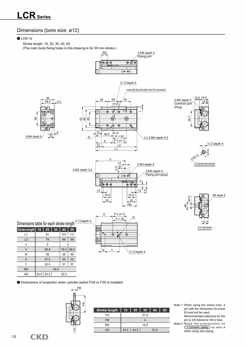
Dimensions (bore size: ø12) LCR-12
Stroke length: 10, 20, 30, 40, 50(The main body fixing holes in this drawing is for 30 mm stroke.)
Stroke length 10 20 30 40 50L1 91 101 111
L2 79 89 99
n 2 3
V 66.5 76.5 86.5
W 26 36 46
X 37.5 36 32
Y 32.5 31 57
RD 16.5
HD 52.5 42.5 32.5
Dimensions table for each stroke length
Note 1: When using the dowel hole, a pin with the dimension for press fit must not be used.Recommended tolerance for the pin is JIS tolerance m6 or less.
Note 2: R e a d t h e p r e c a u t i o n s o n 1. Common ; piping on intro 4
when using rear piping.
Stroke length 10 20 30 40 50FA 37.8
FB 4
RD 15.5
HD 53.5 43.5 33.5
Dimensions of projection when cylinder switch F2S or F3S is installed.
CKDF2H
CKDF2H
RD 2-M5 depth 4Piping port
26 25 W
n-main body fixing hole (refer to the A-A' cross section.)
A
11
304052
D
938.5 A'
12 L2L1
P = 30P x (n-1)X
3 x 2-M4 depth 5.5
V17
5.5
2-M3 depth 3.5
3028.2 0.3
14
30
5
2-M3 depth 5Common port(Plug)
10.5 19.5
34.7
2-R1.5
D, E oval hole section dimension2-M3 depth 5
2-M5 depth 4Piping port (plug)
1315.5
20
15.5
20HD
13 5.5
X P x (n-1)
P = 30 E
Y8
ø8ø4
.5
M5 depth 8
14.3
A-A' cross section
8
5
14.8
FA
FB
3-M4 depth 9
3 depth 4+ 0.05+ 0.02
3 depth 4+ 0.05+ 0.02
3 depth 4+ 0.05+ 0.02
3 depth 4+ 0.05+ 0.02
1

14
LCR SeriesDimensions
Dimensions (bore size: ø12) LCR-12
Stroke length: 75, 100(The main body fixing holes in this drawing is for 100 mm stroke.)
Stroke length 75 100L1 145 170
L2 133 158
V 116 141
W 55 80
X 34.5 47
Y 89.5 102
RD 16.5
HD 41.5
Dimensions table for each stroke length
Note 1: When using the dowel hole, a pin with the dimension for press fit must not be used.Recommended tolerance for the pin is JIS tolerance m6 or less.
Note 2: R e a d t h e p r e c a u t i o n s o n 1. Common ; piping on intro 4
when using rear piping.
Stroke length 75 100FA 37.8
FB 4
RD 15.5
HD 42.5
Dimensions of projection when cylinder switch F2S or F3S is installed.
CKDF2H
Main body fixing hole 05 4- (refer to the A-A' cross section.)
26 25 25 W52 40 30
9
D X 30 30 3012 L2
L1
38.5 4 x 2-M4 depth 5.5
V26
82-M3 depth 5
2-M5 depth 4Piping port (plug)
13 13HD 5.
5
X 30 30 30 E
Y8
FA
FB
3 depth 4+ 0.05+ 0.02
3 depth 4+ 0.05+ 0.02
3 depth 4+ 0.05+ 0.02
15
LCR Series
Dimensions (bore size: ø16) LCR-16
Stroke length: 10, 20, 30, 40, 50(The main body fixing holes in this drawing is for 30 mm stroke.)
Stroke length 10 20 30 40 50L1 96 106 116
L2 83.5 93.5 103.5
n 2 3
V 69.8 79.8 89.8
W 28 38 48
X 34 45.5 35.5
Y 28.5 40 60
T0/5* RD 17
T2/3* HD 56.5 46.5 36.5
T2/3W*RD 19.5
HD 54 44 34
Dimensions table for each stroke length
Note 1: When using the dowel hole, a pin with the dimension for press fit must not be used.Recommended tolerance for the pin is JIS tolerance m6 or less.
Note 2: R e a d t h e p r e c a u t i o n s o n 1. Common ; piping on intro 4
when using rear piping.
CKD
T0H
CKD
T0H
RD 2-M5 depth 4Piping port
n-main body fixing hole (refer to the A-A' cross section.)3835.2 0.3
40
5.5183-M5 depth 9
62 50 40
28 30 WA 11
A'43D
X
9
P = 30P x (n-1)
12.5 L2L1
2-M3 depth 4Common port(Plug)
25.512.5
39.4
1
2-R3
D, E oval hole section dimension
V20.5
10
2-M3 depth 5
2-M4 depth 6
2-M5 depth 4Piping port (plug)
6.5
6
131415.520.2
15.520.2
HD
ø9.5
ø5.5
19.2
M6 depth 9
A-A' cross section
X P x (n-1)P = 30 E
8 Y
3 x 2-M5 depth 6
19.7
6 depth 6+ 0.05+ 0.02
6 depth 6+ 0.05+ 0.02
6 depth 6+ 0.05+ 0.02
6 depth 6+ 0.05+ 0.02

16
LCR SeriesDimensions
Dimensions (bore size: ø16) LCR-16
Stroke length: 75, 100, 125(The main body fixing holes in this drawing is for 75 mm stroke.)
Stroke length 75 100 125L1 158 183 208
L2 145.5 170.5 195.5
n 4 5
V 123.3 148.3 173.3
W 60 85 110
X 39 37 49
Y 93.5 121.5 133.5
T0/5* RD 17
T2/3* HD 53.5
T2/3W*RD 19.5
HD 51
Dimensions table for each stroke length
Note 1: When using the dowel hole, a pin with the dimension for press fit must not be used.Recommended tolerance for the pin is JIS tolerance m6 or less.
Note 2: R e a d t h e p r e c a u t i o n s o n 1. Common ; piping on intro 4
when using rear piping.
CKD
T0H
n-main body fixing hole (refer to the A-A' cross section.)
28 30 30 W62 50 40
D9
43P = 30
X12.5
P x (n-1)L2L1
4 x 2-M5 depth 6
V
4.5 37.5
10
14 13HD 6.
5
2-M4 depth 6
2-M5 depth 4Piping port (plug)
P x (n-1)XE
8 Y
P = 30
6 depth 6+ 0.05+ 0.02
6 depth 6+ 0.05+ 0.02
6 depth 6+ 0.05+ 0.02

17
LCR Series
Dimensions (bore size: ø20) LCR-20
Stroke length: 10, 20, 30, 40, 50(The main body fixing holes in this drawing is for 30 mm stroke.)
Dimensions table for each stroke length
Note 1: When using the dowel hole, a pin with the dimension for press fit must not be used.Recommended tolerance for the pin is JIS tolerance m6 or less.
Note 2: R e a d t h e p r e c a u t i o n s o n 1. Common ; piping on intro 4
when using rear piping.
Stroke length 10 20 30 40 50L1 110.5 120.5 130.5
L2 95.5 105.5 115.5
V 78.5 88.5 98.5
W 28.5 38.5 48.5
X 45 51 49
Y 34 40 38
T0/5* RD 20.5
T2/3* HD 65 55 45
T2/3W*RD 22
HD 63 53 43
CKD
T0H
CKD
T0H
RD 2-Rc1/8Piping port
Main body fixing hole 05 2- (refer to the A-A' cross section.)
32 35 W4844.7 0.3
37
10.5
21.53-M5 depth 11
3776 54
A 1
D A'
49.540
15 L2L1
3 x 2-M5 depth 611
51
15 3325.5
2-R3
D, E oval hole section dimension
2-M5 depth 7V
199
8 9
1921
29.2HD
20.5
29.2
21
2-M4 depth 6
2-Rc1/8Piping port (plug)
M6 depth 9
ø9.5
ø5.5
24.8
A-A' cross section
X 40 E
16 Y
1
X
2-M5 depth 5Common port (plug)
6
1
6 depth 6+ 0.05+ 0.02
6 depth 6+ 0.05+ 0.02
6 depth 6+ 0.05+ 0.02
6 depth 6+ 0.05+ 0.02

18
LCR SeriesDimensions
Dimensions (bore size: ø20) LCR-20
Stroke length: 75, 100, 125, 150(The main body fixing holes in this drawing is for 100 mm stroke.)
Dimensions table for each stroke length
Note 1: When using the dowel hole, a pin with the dimension for press fit must not be used.Recommended tolerance for the pin is JIS tolerance m6 or less.
Note 2: R e a d t h e p r e c a u t i o n s o n 1. Common ; piping on intro 4
when using rear piping.
Stroke length 75 100 125 150L1 167 192 217 242
L2 152 177 202 227
n 3 4 5
V 129.3 154.3 179.3 204.3
W 50 75 100 125
X 46 53 51
Y 75 115 122 160
T0/5* RD 20.5
T2/3* HD 57.5
T2/3W*RD 22
HD 55.5
CKD
T0H
n-main body fixing hole (refer to the A-A' cross section.)
32 35 35 W76 54 37
1149.5
X
D
P = 40P x (n-1)
15 L2L1
4 x 2-5 depth 6
V30.5
9
6
20.5
2-M4 depth 6
2-Rc1/8Piping port (plug)
8
19HD
X P x (n-1)
P = 40
16 Y
E
6 depth 6+ 0.05+ 0.02
6 depth 6+ 0.05+ 0.02
6 depth 6+ 0.05+ 0.02

19
LCR Series
Dimensions (bore size: ø25) LCR-25
Stroke length: 10, 20, 30, 40, 50(The main body fixing holes in this drawing is for 30 mm stroke.)
Dimensions table for each stroke length
Note 1: When using the dowel hole, a pin with the dimension for press fit must not be used.Recommended tolerance for the pin is JIS tolerance m6 or less.
Note 2: R e a d t h e p r e c a u t i o n s o n 1. Common ; piping on intro 4
when using rear piping.
Stroke length 10 20 30 40 50L1 122.5 132.5 142.5
L2 107.5 117.5 127.5
n 2 3 2
V 83.8 93.8 103.8
W 35.5 45.5 55.5
X 42.5 45.5 60.5
Y 39 42 57
T0/5* RD 19
T2/3* HD 78.5 68.5 58.5
T2/3W*RD 21
HD 76.5 66.5 56.5
CKD
T0H
RD 2-Rc1/8Piping port
32 35 W
91 72 46
111
49.5P = 40
P x (n-1)15 L2
L1
V
X
6053.7 0.3
46
14.527.5
2-Rc1/8Common port(Plug)
21 3930.6
68.8
2-R3
D, E oval hole section dimension
26.5122-M5 depth 7
2129
19 192129
HD
2-M5 depth 7
2-Rc1/8Piping port (plug)
109
M8 depth 12
33
ø11
ø6.8
P x (n-1)X
Y8.5
P = 40 EA-A' cross section
1
6
3
3-M6 depth 113 x 2-M6 depth 7
6 depth 6+ 0.05+ 0.02
6 depth 6+ 0.05+ 0.02
6 depth 6+ 0.05+ 0.02
20
LCR SeriesDimensions
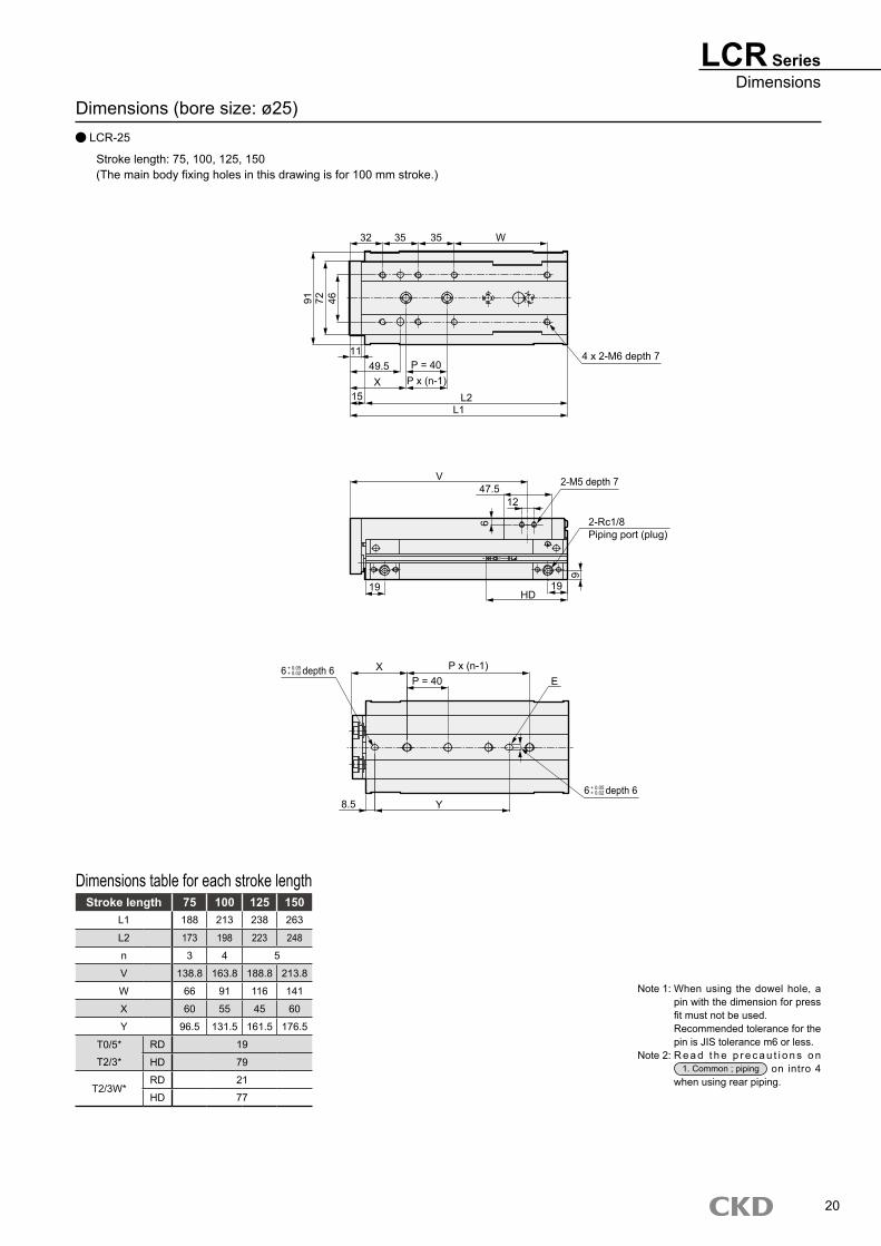
Dimensions (bore size: ø25) LCR-25
Stroke length: 75, 100, 125, 150(The main body fixing holes in this drawing is for 100 mm stroke.)
Dimensions table for each stroke length
Note 1: When using the dowel hole, a pin with the dimension for press fit must not be used.Recommended tolerance for the pin is JIS tolerance m6 or less.
Note 2: R e a d t h e p r e c a u t i o n s o n 1. Common ; piping on intro 4
when using rear piping.
Stroke length 75 100 125 150L1 188 213 238 263
L2 173 198 223 248
n 3 4 5
V 138.8 163.8 188.8 213.8
W 66 91 116 141
X 60 55 45 60
Y 96.5 131.5 161.5 176.5
T0/5* RD 19
T2/3* HD 79
T2/3W*RD 21
HD 77
CKD
T0H
32 35 35 W
91 72 46
1149.5 P = 40
P x (n-1)15 L2
L1
V47.5
12
6
19
2-M5 depth 7
2-Rc1/8Piping port (plug)
919
HD
X P x (n-1)P = 40 E
8.5 Y
X
4 x 2-M6 depth 7
6 depth 6+ 0.05+ 0.02
6 depth 6+ 0.05+ 0.02

LCR Series
Dimensions: Options Stopper for adjustable stroke (S1 to S6)
Shock absorber type stopper (A1 to A6)
SymbolA B C D E F G H I J K L
Shock absorber type stopperAdjustable stroke range (single)Bore size (mm)
ø6 14 19.5 11 4 1 13.5 10.5 24 M3 depth 3 21 9 M3 depth 3 9
ø8 15.6 24.5 9.5 0.5 0.5 10.5 10.5 27.3 M5 depth 4 25.5 16 M5 depth 4 17
ø12 15.5 29 12 1 1 13 13 31 M5 depth 4 25.5 12.5 M5 depth 4 14.5
ø16 18 37 10 2 1 14 13 39 M5 depth 4 28.5 14 M5 depth 4 15
ø20 20.5 45 14.5 4 2.5 20.5 19 46 Rc1/8 29.5 10.5 M5 depth 4 13
ø25 20.5 57 11.5 2.5 2.5 19 19 54.5 Rc1/8 26.5 9 M5 depth 4 10
Note 1: The dimensions of F, H, L are only for when there is a stopper section port (*S*D, A*D)Note 2: The adjustable stroke range of the stopper for adjustable stroke is 5mm per side.Note 3: For position locking function type, S3** to S6** and A3** to A6** are not available.
For ø8
For ø8
21
2-IPiping port
FD
GE
B
C
A
C2-LPiping port
H
9.5
3.53.5 3.5 9.5
2-IPiping port
2-LPiping port
B
J
K
A
J
H
3.53.525.5 25.5
LCR SeriesOptional dimensions
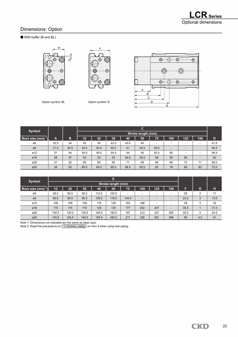
Dimensions: Option With buffer (B and BL)
SymbolC
Stroke length (mm)Bore size (mm) A B 10 20 30 40 50 75 100 125 150 D
ø6 22.5 34 45 45 42.5 43.5 45 - - - - 41.5
ø8 21.5 34.5 42.5 42.5 42.5 41 42.5 39.5 - - - 44.5
ø12 27 44 55.5 55.5 55.5 54 50 52.5 65 - - 56.5
ø16 28 47 53 53 53 64.5 54.5 58 56 68 - 62
ø20 31 52 65 65 65 71 69 66 66 73 71 69.5
ø25 34 55 65.5 65.5 65.5 68.5 83.5 83 78 68 83 72.5
SymbolE
Stroke length (mm)Bore size (mm) 10 20 30 40 50 75 100 125 150 F G H
ø6 82.5 82.5 92.5 112.5 122.5 - - - - 20 3 11
ø8 80.5 80.5 90.5 109.5 119.5 144.5 - - - 23.5 3 13.5
ø12 109 109 109 119 129 163 188 - - 29 3 16
ø16 115 115 115 125 135 177 202 227 - 35.5 1 21.5
ø20 130.5 130.5 130.5 140.5 150.5 187 212 237 262 45.5 4 24.5
ø25 145.5 145.5 145.5 155.5 165.5 211 236 261 286 56 4.5 31
Note 1: Dimensions not indicated are the same as basic type.Note 2: Read the precautions on 1. Common ; piping on intro 4 when using rear piping.
22
H
G
Option symbol: BL Option symbol: B
ABC
DE
F

Linear slide cylinder Double acting position locking type
LCR-Q Series Bore size: ø8, ø12, ø16, ø20, ø25
SpecificationsDescriptions LCR-Q
Bore size mm ø8 ø12 ø16 ø20 ø25Actuation Double actingWorking fluid Compressed airMax. working pressure MPa 0.7Min. working pressure MPa 0.15Withstanding pressure MPa 1Ambient temperature °C -10 to 60 (no freezing)
Port sizeBody side surface M5 Rc1/8Rear body None
Stroke tolerance mm+ 2.0
(Note 1)0
Working piston speed mm/s 50 to 500Cushion Rubber cushionedPosition locking mechanism Head endHolding force N Theoretical thrust x 0.7 at PULL (0.7MPa)Lubrication Not required (when lubricating, use turbine oil Class 1 ISOVG 32.)Allowable energy absorption J Refer to the table 3 on Page 49.
Stroke length
Note: Stroke length other than the ones listed above is not available.
Bore size (mm) Standard stroke length (mm)ø8 10, 20, 30, 40, 50, 75ø12 10, 20, 30, 40, 50, 75, 100ø16 10, 20, 30, 40, 50, 75, 100, 125ø20 10, 20, 30, 40, 50, 75, 100, 125, 150ø25 10, 20, 30, 40, 50, 75, 100, 125, 150
Note 1: There will be a slight gap between the end plate and floating bush if used without a stopper.
Specifications with bufferDescriptions LCR-Q with buffer
Bore size mm ø8 ø12 ø16 ø20 ø25Buffer stroke mm 4 9 10Buffer section spring load
When set N 5 10 13 17 21Operation N 8 14 20 25 29
Specifications other than below are the same as the above common specifications.
Note 1: If the rod side stroke is adjusted with the buffer, the buffer stroke will be shortened as much as the stroke that has been adjusted, and the buffer section spring load will increase during setting.
Note 2: Use buffer stroke below the stroke listed above. There is a risk of damage and malfunction.
JIS symbol
23

LCR-Q SeriesSpecifications
Cylinder weight Position locking type (Unit: g)
Additional option
Bore size Basic type mm stroke (mm)(mm) 10 20 30 40 50 75 100 125 150ø8 260 260 280 330 360 420 - - -ø12 415 425 425 465 495 625 715 - -ø16 670 680 680 730 790 1,020 1,150 1,290 -ø20 1,150 1,160 1,170 1,250 1,340 1,640 1,850 2,060 2,270ø25 2,000 2,020 2,030 2,140 2,240 2,730 3,000 3,270 3,540
Bore size Option, stopper symbol With buffer(mm) S1 S2 A1 A2 B/BLø8 40 50 40ø12 70 80 70ø16 110 120 80ø20 170 180 150ø25 290 300 320
(Unit: g)
24
Switch specifications 1 color/2 color indicator
DescriptionsProximity 2 wire Proximity 3 wire Proximity 2 wire Proximity 3 wire
F2S F3S F2H/F2V F2YH/F2YV F3H/F3V F3YH/F3YV
ApplicationsProgrammable
controllerProgrammable
controller and relayProgrammable
controllerProgrammable
controller and relayOutput method - NPN output - NPN outputPower voltage - 10 to 28 VDC - 10 to 28 VDCLoad voltage 10 to 30 VDC 30 VDC or less 10 to 30 VDC 24 VDC 10% 30 VDC or lessLoad current 5 to 20mA 50mA or less 5 to 20mA 100mA or less 50mA or less
LightRed LED
(ON lighting)LED
(ON lighting)
Red/greenLED
(ON lighting)
LED(ON lighting)
Red/greenLED
(ON lighting)Leakage current 1mA or less 10 A or less 1mA or less 10 A or less
DescriptionsReed 2 wire Proximity 2 wire Proximity 3 wire
T0H/T0V T5H/T5V T2H/T2V T2WH/T2WV T3H/T3V T3WH/T3WV
ApplicationsProgrammable
controller and relayProgrammable controller, relay IC circuit (w/o light), serial connection
Programmablecontroller
Programmablecontroller and relay
Output method - - - NPN outputPower voltage - - - 10 to 28 VDCLoad voltage 12/24 VDC 110 VAC 5/12/24 VDC 110 VAC 10 to 30 VDC 24 VDC 10% 30 VDC or lessLoad current 5 to 50mA 7 to 20mA 50mA or less 20mA or less 5 to 20mA 100mA or less 50mA or less
LightLED
(ON lighting)Without indicator light
LED(ON lighting)
Red/greenLED
(ON lighting)
LED(ON lighting)
Red/greenLED
(ON lighting)Leakage current 0mA 1mA or less 10 A or less
* T0/T5 switches can be used under 220VACConsult CKD for working conditions
Structure that can be used in secondary battery manufacturing process.
* Consult with CKD for details.
P4*LCR-: -
Secondary battery compatible specification
LCR-Q Series
E
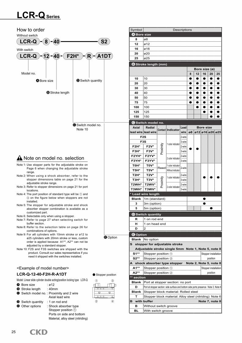
How to orderWithout switch
With switch
Note on model no. selectionNote 1: Use stopper parts for the adjustable stroke on
Page 6 when changing the adjustable stroke range.
Note 2: When using a shock absorber, refer to the stopper dimensions table on page 21 for the adjustable stroke range.
Note 3: Refer to stopper dimensions on page 21 for port locations.
Note 4: The port position of standard type will be 1 and 3 on the figure below when stoppers are not installed.
Note 5: The stopper for adjustable stroke and shock absorber stopper combination is available as a customized part.
Note 6: Selectable only when using a stopper.Note 7: Refer to page 27 when selecting switch for
buffer section.Note 8: Refer to the selection table on page 26 for
combinations of options.Note 9: For ø8 cylinders with 10mm stroke or ø12 to
ø25 cylinders with 20mm stroke or less, custom order is applied because A1**, A2** can not be adjusted by a standard stopper.
Note 10: F2S and F3S switches are shipped with the product. Consult our sales representative if you need it shipped with the switches installed.
<Example of model number>LCR-Q-12-40-F2H-R-A1DTModel: Linear slide cylinder double acting/position locking type LCR-QA Bore size : ø12B Stroke length : 40mmC Switch model no. : Proximity and 2 wire Axial lead wireD Switch quantity : 1 on rod endE Other options : Shock absorber type Stopper position 1
Ports on side and bottom Material, alloy steel (nitriding)
LCR-Q S2408
Model no.
Bore sizeA
Stroke lengthB
LCR-Q 4012 F2H* R A1DT
Symbol DescriptionsBore size8 ø8
12 ø1216 ø1620 ø2025 ø25
Stroke length (mm)Bore size (ø)
8 12 16 20 2510 1020 2030 3040 4050 5075 75
100 100125 125150 150
Switch model no.Axial
lead wireRadial
lead wireContact Indicator
Lead wire
Bore sizeø8 ø12 ø16 ø20 ø25
F2S
Prox
imity 1 color indicator
2-wireF3S 3-wire
F2H* F2V* 2-wireF3H* F3V* 3-wire
F2YH* F2YV*2 color indicator
2-wireF3YH* F3YV* 3-wireT0H* T0V*
Reed1 color indicator
2-wireT5H* T5V* Without indicatorT2H* T2V*
Prox
imity 1 color indicator
2-wireT3H* T3V* 3-wire
T2WH* T2WV*2 color indicator
2-wireT3WH* T3WV* 3-wire* Lead wire lengthBlank 1m (standard)
3 3m (option)5 5m (option)
Switch quantityR 1 on rod endH 1 on head endD 2
OptionBlank No option
S stopper for adjustable strokeAdjustable stroke single 5mm Note 1, Note 5, note 8
S1** Stopper position 1 Stopper installationpositionS2** Stopper position 2
A shock absorber type stopper Note 2, Note 5, note 8A1** Stopper position 1 Stopper installation
positionA2** Stopper position 2
** sectionBlank Port at stopper section: no port
D Port at stopper section: side surface and bottom side ports presence Note 3, Note 6Blank Stopper block material: Rolled steel
T Stopper block material: Alloy steel (nitriding) Note 6B with buffer Note 7, note 8
B Without switch grooveBL With switch groove
A
B
Switch model no.Note 10
C
Switch quantityD
Option
Stopper position
C
D
E
25
1 3
2 4

LCR-Q SeriesHow to order
LCR-Q position locking type combination availability table(Combinations of stopper for adjustable stroke and shock absorber type stopper) : Combination available -: Combination not available
Model no. symbolOption symbol Stopper for adjustable stroke Shock absorber type stopper
Bore size Stroke length S1 S2 S3 S4 S5 S6 A1 A2 A3 A4 A5 A6
LCR-QLCR-Q-B and BL
ø810 ― ― ― ― ― ― ― ― ― ―
20 and over ― ― ― ― ― ― ― ―
ø12 to ø2510 to 20 ― ― ― ― ― ― ― ― ― ―
30 and over ― ― ― ― ― ― ― ―
Combination of option symbol “D: with stopper section port” and “T: alloy steel (nitriding) ” follows the chart shown above.
26

LCR-Q Series
Switch model no.(Page 25, section C )
Switch model no.(Page 25, section C )
How to order switch
For ø8 to ø12 For ø16 to ø25
How to order stopper set Stopper section and stopper for adjustable stroke or shock absorber type stopper set Use when changing from standard to stopper for adjustable stroke or with shock absorber stopper
SW F2H SW T2H3
Stopper typeS Stopper for adjustable strokeA Shock absorber type stopper
Stopper installation position Note 11 For stopper position 1 or 4
2 For stopper position 2 or 3
Port at stopper sectionBlank No port
D With side and bottom port
Adjustable stroke length Note 2 Note 3Blank Adjustable stroke range 5mmS02 Adjustable stroke range 15mmS03 Adjustable stroke range 25mm
ABore size(Page 25 section A )
LCR S12 2 D
B
C
Precautions when ordering stopper set
SO1 is included as the stopper for adjustable stroke in the stopper for adjustable stroke set.When installing on 1 , 2 (refer to page 25), add the parts on the right according to the stroke and stroke adjustment.
Model no. symbolOption symbol
Discrete stopper for adjustable strokeAdjusted stroke length (mm)
Bore size Stroke length -5 -15 -25
LCR-Q Series
ø810 S02 ― ―
20 and over Not required additionally S02 ―
ø12 to ø2510 S03 ― ―20 S02 S03 ―
30 and over Not required additionally S02 S03
―: not available
SW F 2 V 3 Buffer
Output type2 2 wire proximity DC3 3 wire proximity DC
Radial lead wire
Lead wire lengthBlank 1m (standard)
3 3m (option)
27
Note 1: Refer to the chart below when attaching stopper on 1 or 2 because the stroke adjustment changes according to the stroke.
Note 2: "S03" can not be selected with ø6 or ø8.Note 3: Can not be selected with shock absorber
type stopper "A".
D
S02

LCR-Q SeriesHow to order
How to order the discrete stopper for adjustable stroke Hexagon socket head set screw with urethane Use when changing the adjustable stroke range or setting to custom stroke length.
Adjustable stroke rangeS01 Single 5mm (standard)S02 Single 15mmS03 Single 25mm
ABore size(Page 25 section A )
LCR 12 S02
Precautions when ordering discrete stopper
Please be warned that when installing discrete stopper for stroke adjustment, discrete shock absorber type stopper on positions 1 and 2 (refer to page 25), the available combination will be as shown on the right.
Model no. symbolOption symbol
Discrete stopper for adjustable strokeDiscrete shock
absorber type stopperAdjusted stroke length (mm)
Bore size Stroke length -5 -15 -25
LCR Series-S1, S2-A1, A2
ø810 S02 ― ― ―
20 and over S01 S02 ― A01
ø12 to ø2510 S03 ― ― ―20 S02 S03 ― ―
30 and over S01 S02 S03 A01
―: combination not available
How to order the discrete shock absorber stopper Set of shock absorber and stopper cap Used when changing from shock absorber type stopper to stopper for adjustable stroke
Model Shock absorber model no.LCR-8 NCK-00-0.3LCR-12 NCK-00-0.3LCR-16 NCK-00-0.7LCR-20 NCK-00-1.2LCR-25 NCK-00-1.2
Bore size(Page 25 section A )
LCR 12 A01
Discrete stopper block model no. display Use when changing from standard to stopper for adjustable stroke or with shock absorber stopper
Stopper block
SB1ø8: 30 mm stroke or lessø12 to ø25: 50 mm stroke or less
SB2ø8: 40 mm stroke and overø12 to ø25: 75 mm stroke and over
MaterialBlank Stopper block material: Rolled steel
T Stopper block material: Alloy steel (nitriding)
ABore size(Page 25 section A )
LCR 12 SB1
Applicable shock absorber model No.
Note: Some models may not be available depending on the type. Refer to Page 25.Refer to page 21 for the stroke adjustment range of shock absorber type stopper.
T
B
Specify the S01, S02, S03 at the A section.Note: S03 is not available for ø8.
Depending on the type, the incompatible models or adjustable stroke ranges may differ from the above values.
28
Shock absorber
Stopper cap

LCR-Q Series
Internal structure and parts list LCR-Q
No. Parts name Material Remarks No. Parts name Material Remarks1 End plate Aluminum alloy Alumite 7 Hexagon socket head cap bolt Alloy steel Zinc chromate
2 Guard Aluminum alloy 8 Coil spring Steel
3 Gasket Nitrile rubber 9 Stopper guard Aluminum alloy Alumite
4 Joint ringø8: stainless steel
ø12 to 25: chromate10 Stopper piston Carbon steel Nitriding
ø12 to 25: aluminum alloy 11 Stopper packing seal Nitrile rubber
5 Sleeve Carbon steel Nitriding 12 Head cover Aluminum alloy Alumite
6 Hexagon socket head cap bolt Alloy steel Zinc chromate
Parts list
Bore sizeKit No.
Repair parts number(mm) Position locking unit repair parts Basic unit repair parts
ø8 LCR-Q-8K
114 5 9
11 17 21
ø12 LCR-Q-12K
ø16 LCR-Q-16K
ø20 LCR-Q-20K
ø25 LCR-Q-25K
Repair parts list
Note: Consumable parts for the base is compatible with the double acting, single rod type parts listed on page 7.
29
Y
Y'
Y-Y' cross section
1 2 3 4 5 6 7 8 9 10 11 12

Dimensions LCR-Q
LCR-Q SeriesDimensions
LCR-Q-*-*-B (with buffer)
SymbolA B C
Bore size (mm)ø8 23 29.5 22
ø12 24.5 30.5 24.5
ø16 28 35.7 29.7
ø20 30 39 33
ø25 30 48 42
Note: Dimensions not listed above are the same as double acting single rod type.
30
Basic type head end edge position
A2
Tap for M3 depth 3 stopper release
BC
Basic type head end edge position with buffer
A2
Tap for M3 depth 3 stopper release
BC

Linear slide cylinder Double acting single rod type, clean room specifications
LCR-P7* Series Bore size: ø6, ø8, ø12, ø16, ø20, ø25
SpecificationsDescriptions LCR-P7*
Bore size mm ø6 ø8 ø12 ø16 ø20 ø25Actuation Double actingWorking fluid Compressed airMax. working pressure MPa 0.7Min. working pressure MPa 0.15Withstanding pressure MPa 1Ambient temperature °C -10 to 60 (no freezing)
Port sizeBody side surface M3 M5 Rc1/8Rear body M3 M5 Rc1/8
Relief port size M3 M5 Rc1/8
Stroke tolerance mm+ 2.0
(Note 1)0
Working piston speed mm/s 50 to 500Cushion Rubber cushionedLubrication Not availableAllowable energy absorption J Refer to the table 3 on Page 49.
Stroke length
Note: Stroke length other than above is not available.
Bore size (mm) Standard stroke length (mm)ø6 10, 20, 30, 40, 50ø8 10, 20, 30, 40, 50, 75ø12 10, 20, 30, 40, 50, 75, 100ø16 10, 20, 30, 40, 50, 75, 100, 125ø20 10, 20, 30, 40, 50, 75, 100, 125, 150ø25 10, 20, 30, 40, 50, 75, 100, 125, 150
Note 1: There will be a slight gap between the end plate and floating bush if used without a stopper.
JIS symbol
31
LCR-P7* SeriesSpecifications
Cylinder weight Clean room specifications
Bore size Basic stroke length types (mm)(mm) 10 20 30 40 50 75 100 125 150ø6 130 130 150 180 200 - - - -ø8 220 220 240 290 320 380 - - -ø12 400 410 410 450 480 610 700 - -ø16 620 630 630 680 740 970 1,100 1,240 -ø20 1,160 1,170 1,180 1,260 1,350 1,650 1,860 2,070 2,280ø25 2,010 2,030 2,040 2,150 2,250 2,740 3,010 3,280 3,550
(Unit: g)
Additional weight for variations/options (stopper)Bore size Option, stopper symbol
(mm) S1 to S4 S5/S6ø6 30 40ø8 40 60ø12 70 100ø16 110 150ø20 170 250ø25 290 380
(Unit: g)
32
Switch specifications 1 color/2 color indicator
DescriptionsProximity 2 wire Proximity 3 wire Proximity 2 wire Proximity 3 wire
F2S F3S F2H/F2V F2YH/F2YV F3H/F3V F3YH/F3YV
ApplicationsProgrammable
controllerProgrammable
controller and relayProgrammable
controllerProgrammable
controller and relayOutput method - NPN output - NPN outputPower voltage - 10 to 28 VDC - 10 to 28 VDCLoad voltage 10 to 30 VDC 30 VDC or less 10 to 30 VDC 24 VDC 10% 30 VDC or lessLoad current 5 to 20mA 50mA or less 5 to 20mA 100mA or less 50mA or less
LightRed LED
(ON lighting)LED
(ON lighting)
Red/greenLED
(ON lighting)
LED(ON lighting)
Red/greenLED
(ON lighting)Leakage current 1mA or less 10 A or less 1mA or less 10 A or less
DescriptionsReed 2 wire Proximity 2 wire Proximity 3 wire
T0H/T0V T5H/T5V T2H/T2V T2WH/T2WV T3H/T3V T3WH/T3WV
ApplicationsProgrammable
controller and relayProgrammable controller, relay IC circuit (w/o light), serial connection
Programmablecontroller
Programmablecontroller and relay
Output method - - - NPN outputPower voltage - - - 10 to 28 VDCLoad voltage 12/24 VDC 110 VAC 5/12/24 VDC 110 VAC 10 to 30 VDC 24 VDC 10% 30 VDC or lessLoad current 5 to 50mA 7 to 20mA 50mA or less 20mA or less 5 to 20mA 100mA or less 50mA or less
LightLED
(ON lighting)Without indicator light
LED(ON lighting)
Red/greenLED
(ON lighting)
LED(ON lighting)
Red/greenLED
(ON lighting)Leakage current 0mA 1mA or less 10 A or less
* T0/T5 switches 220 VAC are also available.Consult CKD for working conditions.

Switch quantityD
LCR-P7* Series
E
How to orderWithout switch
With switch
Note on model no. selectionNote 1: Refer to stopper dimensions on page 21 for port
locations.Note 2: The port position of standard type will be 1 and
3 on the figure below when stoppers are not installed.
Note 3: Selectable only when using a stopper.Note 4: Select F H type switch when using S**** ø6 to
8 under 30th with 2 switches.Note 5: F2S and F3S switches are shipped with the
product. Consult our sales representative if you need it shipped with the switches installed.
Note 6: Select by rear piping for use.
<Example of model number>LCR-12-40-F2H*-R-S1DT-P72Type: Linear slide cylinder Double acting, single rod type (clean specification) LCR-P7*A Bore size : ø12B Stroke length : 40mmC Switch model no. : Proximity, 2 wire Axial lead wireD Switch quantity : 1 on rod endE Other options : Stopper for adjustable stroke Stopper position 1
Ports on side and bottom Material, alloy steel (nitriding)F Clean room specifications: Exhaust treatment
LCR S5408
Model no.
Bore sizeA
Stroke lengthB
LCR 4012 F2H* R S1DT
Switch model no.Note 5
C
Option
Stopper position
P72
P72
Clean room specificationsF
Symbol DescriptionsBore size6 ø68 ø8
12 ø1216 ø1620 ø2025 ø25
Stroke length (mm)Bore size (ø)
6 8 12 16 20 2510 1020 2030 3040 4050 5075 75
100 100125 125150 150
Switch model no.Axial
lead wireRadial
lead wireContact Indicator
Lead wire
Bore sizeø6 ø8 ø12 ø16 ø20 ø25
F2S
Prox
imity 1 color indicator
2-wireF3S 3-wire
F2H* F2V* 2-wireF3H* F3V* 3-wire
F2YH* F2YV*2 color indicator
2-wireF3YH* F3YV* 3-wireT0H* T0V*
Reed1 color indicator
2-wireT5H* T5V* Without indicatorT2H* T2V*
Prox
imity 1 color indicator2-wire
T3H* T3V* 3-wireT2WH* T2WV*
2 color indicator2-wire
T3WH* T3WV* 3-wireLead wire lengthBlank 1m (standard)
3 3m (option)5 5m (option)
Switch quantityR 1 on rod endH 1 on head endD 2
OptionBlank No option
S stopper for adjustable strokeAdjustable stroke single 5mm Note 4
S1** Stopper position 1 (changeable to 4 )
Stopp
er ins
tallatio
n posi
tion
S2** Stopper position 2 (changeable to 3 )S3** Stopper position 3 (changeable to 2 )S4** Stopper position 4 (changeable to 1 )S5** Stopper position 1 and 3
S6** Stopper position 2 and 4
** sectionBlank Port at stopper section: no port
D Port at stopper section: side surface and bottom side ports presence Note 1, Note 3
Blank Stopper block material: Rolled steelT Stopper block material: Alloy steel (nitriding) Note 3
Plug attachedBlank None
N Port for side piping port attached (Not selectable for ø6 and ø25)) Note 6
Clean room specificationsStructure
P72 Exhaust treatmentP73 Vacuum treatment
A
B
C
D
E
F
33
1
4
3
2

34
M E M OM E M O

LCR-P7* Series
Stroke length 10 20 30L1 78 88
L2 70 80
V 60.5 70.5
W 25.5 35.5
X 40.5 38
Y 45.5 43
RD 27
HD 33 23
Dimensions table for each stroke length
Dimensions (bore size: ø6) LCR-6-P7*
Stroke length: 10, 20, 30(The main body fixing holes in this drawing is for 20 mm stroke.)
Note 1: When using the dowel hole, a pin with the dimension for press fit must not be used.Recommended tolerance for the pin is JIS tolerance m6 or less.
35
Dimensions of projection when cylinder switch F2S or F3S is installed.
Stroke length 10 20 30FA 29.1
FB 4
RD 26
HD 34 24
M3 depth 3Relief port
19
19.321
0.2
RD 2-M3 depth 3Piping port
Main body fixing hole 05 2- (refer to the A-A' cross section.)
29.5 15 W
3 Depth 3+ 0.05+ 0.02
A 0.6
1
33 25 19
4103-M3 depth 6
18
37X
D
820
A'
L2L1
3 x 2-M3 depth 3
2-M2.6 depth 3.5
M3 depth 3Relief port (plug)
2-M2.6 depth 2.6
2-M3 depth 3Piping port (plug)
V13
6.5
12
25.511
16
11
16HD
10.5
2.6
4
3 Depth 3+ 0.05+ 0.02
X 20 E
17 Y3 Depth 3+ 0.05
+ 0.02
D, E oval hole section dimension
2-R1.5
12.88.2
M4 depth 6
ø3.4
ø6.6
10.4
A-A' cross section
1
FB
FA
3 Depth 3+ 0.05+ 0.02

Dimensions (bore size: ø6) LCR-6-P7*
Stroke length: 40, 50(The main body fixing holes in this drawing is for 50 mm stroke.)
LCR-P7* SeriesDimensions
Stroke length 40 50L1 108 118
L2 100 110
n 3 4
V 86 96
W 40.5 50.5
X 39 40.5
Y 44 65.5
RD 27
HD 23
Dimensions table for each stroke length
Note 1: When using the dowel hole, a pin with the dimension for press fit must not be used.Recommended tolerance for the pin is JIS tolerance m6 or less.
36
Dimensions of projection when cylinder switch F2S and F3S are installed.
Stroke length 40 50FA 29.1
FB 4
RD 26
HD 24
M3 depth 3Relief port RD 2-M3 depth 3
Piping port
3 Depth 3+ 0.05+ 0.02
33 25 19
29.5 15 W
n-main body fixing hole (refer to the A-A' cross section.)
1837X
D
8P x (n-1)
P = 20
L2L1
4 x 2-M3 depth 3
15
M3 depth 3Relief port (plug)
2-M2.6 depth 2.6
2-M3 depth 3Piping port (plug)
V22
1225.5 HD
10.5
2.6
414
3 Depth 3+ 0.05+ 0.02
XE
17 Y 3 Depth 3+ 0.05+ 0.02
P x (n-1)P = 20
FB
FA

Dimensions (bore size: ø8) LCR-8-P7*
Stroke length: 10, 20, 30(The main body fixing holes in this drawing is for 30 mm stroke.)
Stroke length 10 20 30L1 86 96
L2 77 87
V 67.5 77.5
W 16 26
RD 33
HD 34 24
Dimensions table for each stroke length
LCR-P7* Series
Note 1: When using the dowel hole, a pin with the dimension for press fit must not be used.Recommended tolerance for the pin is JIS tolerance m6 or less.
Note 2: R e a d t h e p r e c a u t i o n s o n 1. Common ; piping on intro 4
when using rear piping.
37
Dimensions of projection when cylinder switch F2S or F3S is installed.
Stroke length 10 20 30FA 32.6
FB 4
RD 32
HD 35 25
M5 depth 4Relief port
24
250.3
RD 2-M5 depth 4Piping port
Main body fixing hole 05 2- (refer to the A-A' cross section.)
40 W
3 Depth 3+ 0.05+ 0.02
A
0.6
1
43 30 24
4.5 2750
D
920
A'
L2L1
3 x 2-M3 depth 4.5
2-M2.6 depth 3.5
M5 depth 4Relief port (plug)
M3 depth 3
2-M5 depth 4Piping port (plug)
V13
11
14
18
1114
HD
5.5
5
3 Depth 3+ 0.05+ 0.02
48 20E
26 43 3 Depth 3+ 0.05+ 0.02
D, E oval hole section dimension
2-R1.5
13.58
M4 depth 6
ø3.4
ø6.6
12
A-A' cross section
23.2
9.5
20
48
17
23
2-M3 depth 4Common port(Plug)
31
18
3
1
FB
FA
3-M3 depth 7
3 Depth 3+ 0.05+ 0.02

Dimensions (bore size: ø8) LCR-8-P7*
Stroke length: 40, 50, 75(The main body fixing holes in this drawing is for 50 mm stroke.)
Stroke length 40 50 75L1 115 125 150
L2 106 116 141
n 3 4 5
V 92 102 127
W 25 35 60
X 46.5 48 45
Y 41.5 63 80
RD 33
HD 33
Dimensions table for each stroke length
LCR-P7* SeriesDimensions
Note 1: When using the dowel hole, a pin with the dimension for press fit must not be used.Recommended tolerance for the pin is JIS tolerance m6 or less.
Note 2: R e a d t h e p r e c a u t i o n s o n 1. Common ; piping on intro 4
when using rear piping.
38
Dimensions of projection when cylinder switch F2S or F3S is installed.
Stroke length 40 50 75FA 32.6
FB 4
RD 32
HD 34
40
3 Depth 3+ 0.05+ 0.02
43 30 24
n-main body fixing hole (refer to the A-A' cross section.)
5027
X
D
9P x (n-1)
P = 20
L2L1
4 x 2-M3 depth 4.5
M5 depth 4Relief port
2-M3 depth 3
2-M5 depth 4Piping port (plug)
V22
1131
HD11 5.
5
3
13
3 Depth 4+ 0.05+ 0.02
X
E
26 Y 3 Depth 3+ 0.05+ 0.02
P x (n-1)P = 20
20 20 W
FB
FA
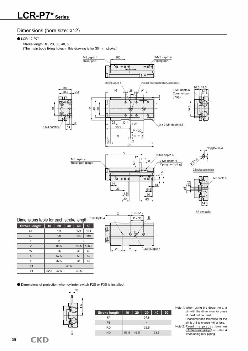
Dimensions (bore size: ø12) LCR-12-P7*
Stroke length: 10, 20, 30, 40, 50(The main body fixing holes in this drawing is for 30 mm stroke.)
Stroke length 10 20 30 40 50L1 111 121 131
L2 99 109 119
n 2 3
V 86.5 96.5 106.5
W 26 36 46
X 57.5 56 52
Y 32.5 31 57
RD 36.5
HD 52.5 42.5 32.5
Dimensions table for each stroke length
LCR-P7* Series
Note 1: When using the dowel hole, a pin with the dimension for press fit must not be used.Recommended tolerance for the pin is JIS tolerance m6 or less.
Note 2: R e a d t h e p r e c a u t i o n s o n 1. Common ; piping on intro 4
when using rear piping.
39
Dimensions of projection when cylinder switch F2S or F3S is installed.
Stroke length 10 20 30 40 50FA 37.8
FB 4
RD 35.5
HD 53.5 43.5 33.5
M5 depth 4Relief port
30
300.3
RD 2-M5 depth 4Piping port
n-main body fixing hole (refer to the A-A' cross section.)
46 W
3 Depth 4+ 0.05+ 0.02
A 1
52 40 30
5 2958.5
D
12
P = 30
A'
L2L1
3 x 2-M4 depth 5.5
M5 depth 4Relief port (plug)
2-M3 depth 5
2-M5 depth 4Piping port (plug)
V17
14
3313
HD
5.5
5
3 Depth 4+ 0.05+ 0.02
XE
28 3 Depth 4+ 0.05+ 0.02
D, E oval hole section dimension
2-R1.5
14.810.5
M5 depth 8
ø4.5
ø8
14.3
A-A' cross section
28.2
14
25
X
19.5
34.7
2-M3 depth 5Common port(Plug)
20
5.5
1
P x (n-1)
15.5
20
8
Y
P = 30
P x (n-1)
1
FA
FB
3-M4 depth 9
3 Depth 4+ 0.05+ 0.02
15.5

Dimensions (bore size: ø12) LCR-12-P7*
Stroke length: 75, 100(The main body fixing holes in this drawing is for 100 mm stroke.)
Stroke length 75 100L1 165 190
L2 153 178
V 136 161
W 55 80
X 54.5 67
Y 89.5 102
RD 36.5
HD 41.5
Dimensions table for each stroke length
LCR-P7* SeriesDimensions
Note 1: When using the dowel hole, a pin with the dimension for press fit must not be used.Recommended tolerance for the pin is JIS tolerance m6 or less.
Note 2: R e a d t h e p r e c a u t i o n s o n 1. Common ; piping on intro 4
when using rear piping.
40
Dimensions of projection when cylinder switch F2S or F3S is installed.
Stroke length 75 100FA 37.8
FB 4
RD 35.5
HD 42.5
46
52 40 30
4-main body fixing hole (refer to the A-A' cross section.)
58.529
X
D
12 L2L1
4 x 2-M4 depth 5.5
M5 depth 4Relief port (plug)
2-M3 depth 5
2-M5 depth 4Piping port (plug)
V26
1433 HD
135.
5
5.5
8
X E
28 Y
25 25 W
30 30 30
30 30 30
FA
FB
3 Depth 4+ 0.05+ 0.02
3 Depth 4+ 0.05+ 0.02
3 Depth 4+ 0.05+ 0.02

Dimensions (bore size: ø16) LCR-16-P7*
Stroke length: 10, 20, 30, 40, 50(The main body fixing holes in this drawing is for 30 mm stroke.)
Stroke length 10 20 30 40 50L1 116 126 136
L2 103.5 113.5 123.5
n 2 3
V 89.8 99.8 109.8
W 28 38 48
X 54 65.5 55.5
Y 28.5 40 60
T0/5* RD 37
T2/3* HD 56.5 46.5 36.5
T2/3W*RD 39.5
HD 54 44 34
Dimensions table for each stroke length
LCR-P7* Series
Note 1: When using the dowel hole, a pin with the dimension for press fit must not be used.Recommended tolerance for the pin is JIS tolerance m6 or less.
Note 2: R e a d t h e p r e c a u t i o n s o n 1. Common ; piping on intro 4
when using rear piping.
41
M5 depth 4Relief port
40
380.3
RD 2-M5 depth 4Piping port
n-main body fixing hole (refer to the A-A' cross section.)
48 W
A 1
62 50 40
5.529
63D
12.5
P = 30
A'
L2L1
3 x 2-M5 depth 6
M5 depth 4Relief port (plug)
2-M4 depth 6
2-M5 depth 4Piping port (plug)
V21
13.534
1315.5
HD
6.5
6
XE
28
D, E oval hole section dimension
2-R3
19.712.5
M6 depth 9ø5
.5ø9
.5
19.2
A-A' cross section
35.2
18
30
X
25.5
39.4
2-M3 depth 4Common port(Plug)
20.2
4.5
1
P x (n-1)
15.5
20.2
10
Y
P = 30
P x (n-1)
3-M5 depth 9
2-M3 depth 5
1
6 Depth 6+ 0.05+ 0.02
6 Depth 6+ 0.05+ 0.02
6 Depth 6+ 0.05+ 0.02
6 Depth 6+ 0.05+ 0.02
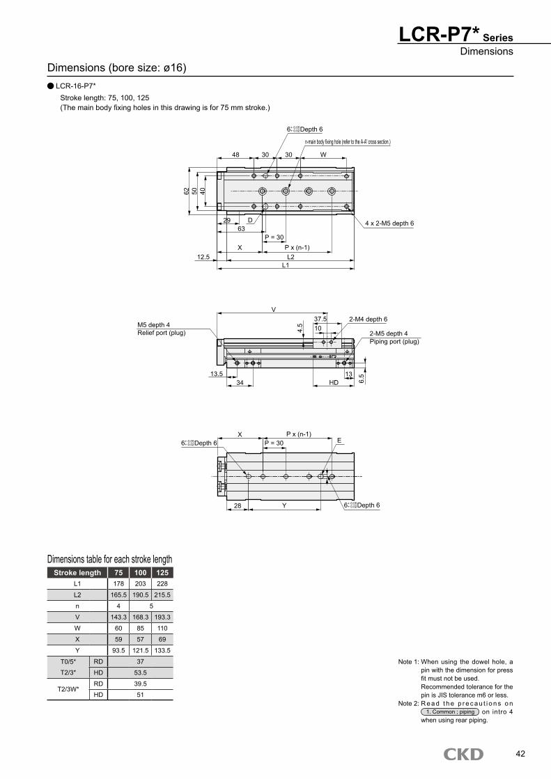
Dimensions (bore size: ø16) LCR-16-P7*
Stroke length: 75, 100, 125(The main body fixing holes in this drawing is for 75 mm stroke.)
Stroke length 75 100 125L1 178 203 228
L2 165.5 190.5 215.5
n 4 5
V 143.3 168.3 193.3
W 60 85 110
X 59 57 69
Y 93.5 121.5 133.5
T0/5* RD 37
T2/3* HD 53.5
T2/3W*RD 39.5
HD 51
Dimensions table for each stroke length
LCR-P7* SeriesDimensions
Note 1: When using the dowel hole, a pin with the dimension for press fit must not be used.Recommended tolerance for the pin is JIS tolerance m6 or less.
Note 2: R e a d t h e p r e c a u t i o n s o n 1. Common ; piping on intro 4
when using rear piping.
42
6 Depth 6+ 0.05+ 0.02
48
62 50 40
n-main body fixing hole (refer to the A-A' cross section.)
6329
X
D
12.5 L2L1
4 x 2-M5 depth 6
M5 depth 4Relief port (plug)
2-M4 depth 6
2-M5 depth 4Piping port (plug)
V37.5
13.534 HD
13
6.5
4.5 10
XE
28 Y
30 30 W
P = 30P x (n-1)
P x (n-1)P = 306 Depth 6+ 0.05
+ 0.02
6 Depth 6+ 0.05+ 0.02

Dimensions (bore size: ø20) LCR-20-P7*
Stroke length: 10, 20, 30, 40, 50(The main body fixing holes in this drawing is for 30 mm stroke.)
Stroke length 10 20 30 40 50L1 135.5 145.5 155.5
L2 120.5 130.5 140.5
V 103.5 113.5 123.5
W 28.5 38.5 48.5
X 70 76 74
Y 34 40 38
T0/5* RD 45.5
T2/3* HD 65 55 45
T2/3W*RD 47
HD 63 53 43
Dimensions table for each stroke length
LCR-P7* Series
Note 1: When using the dowel hole, a pin with the dimension for press fit must not be used.Recommended tolerance for the pin is JIS tolerance m6 or less.
Note 2: R e a d t h e p r e c a u t i o n s o n 1. Common ; piping on intro 4
when using rear piping.
43
Rc1/8Relief port
37
480.3
RD 2-Rc1/8Piping port
Main body fixing hole 05 2- (refer to the A-A' cross section.)
57 WA
1
76 54 37
10.5 3674.5
D
1540
A'
L2L1
3 x 2-M5 depth 6
Rc1/8Relief port (plug)
2-M4 depth 6
2-Rc1/8Piping port (plug)
V19
18.545.5
1921
HD
98
X E
41
D, E oval hole section dimension
2-R3
25.5
15
M6 depth 9
ø5.5
ø9.5
24.8
A-A' cross section
44.7
21.5
35
X
33
51
29.2
6
1
2129.2
9
Y
40
3-M5 depth 11
2-M5 depth 7 1
2-M5 depth 5Common port(Plug)
6 Depth 6+ 0.05+ 0.02
6 Depth 6+ 0.05+ 0.02
6 Depth 6+ 0.05+ 0.02
6 Depth 6+ 0.05+ 0.02

Dimensions (bore size: ø20) LCR-20-P7*
Stroke length: 75, 100, 125, 150(The main body fixing holes in this drawing is for 100 mm stroke.)
Stroke length 75 100 125 150L1 192 217 242 267
L2 177 202 227 252
n 3 4 5
V 154.3 179.3 204.3 229.3
W 50 75 100 125
X 71 78 76
Y 75 115 122 160
T0/5* RD 45.5
T2/3* HD 57.5
T2/3W*RD 47
HD 55.5
Dimensions table for each stroke length
LCR-P7* SeriesDimensions
Note 1: When using the dowel hole, a pin with the dimension for press fit must not be used.Recommended tolerance for the pin is JIS tolerance m6 or less.
Note 2: R e a d t h e p r e c a u t i o n s o n 1. Common ; piping on intro 4
when using rear piping.
44
6 Depth 6+ 0.05+ 0.02
57
76 54 37
n-main body fixing hole (refer to the A-A' cross section.)
74.536
X
D
15 L2L1
4 x 2-M5 depth 6
Rc1/8Relief port (plug)
2-M4 depth 6
2-Rc1/8Piping port (plug)
V30.5
18.545.5 HD
198
6 9
XE
41 Y
35 35 W
P = 40P x (n-1)
P x (n-1)P = 406 Depth 6+ 0.05
+ 0.02
6 Depth 6+ 0.05+ 0.02

Dimensions (bore size: ø25) LCR-25-P7*
Stroke length: 10, 20, 30, 40, 50(The main body fixing holes in this drawing is for 30 mm stroke.)
Stroke length 10 20 30 40 50L1 147.5 157.5 167.5
L2 132.5 142.5 152.5
n 2 3 2
V 108.8 118.8 128.8
W 35.5 45.5 55.5
X 67.5 70.5 85.5
Y 39 42 57
T0/5* RD 44
T2/3* HD 78.5 68.5 58.5
T2/3W*RD 46
HD 76.5 66.5 56.5
Dimensions table for each stroke length
LCR-P7* Series
Note 1: When using the dowel hole, a pin with the dimension for press fit must not be used.Recommended tolerance for the pin is JIS tolerance m6 or less.
Note 2: R e a d t h e p r e c a u t i o n s o n 1. Common ; piping on intro 4
when using rear piping.
45
Rc1/8Relief port
46
60
0.3
RD 2-Rc1/8Piping port
57 W
1
91 72 46
14.5 1174.5
15
P = 40
L2L1
Rc1/8Relief port (plug)
2-M5 depth 7
2-Rc1/8Piping port (plug)
V26.5
1944 19
21
HD
109
XE
33.5
D, E oval hole section dimension
2-R3
30.621
M8 depth 12
ø6.8
ø11
33
A-A' cross section
53.7
27.5
35
X
39
68.8
29
6
21
29
12
Y
P x (n-1)
2-M5 depth 7
1
P = 40
4
P x (n-1)
2-Rc1/8Piping port(Plug)
3 x 2-M6 depth 73-M6 depth 11
6 Depth 6+ 0.05+ 0.02
6 Depth 6+ 0.05+ 0.02
6 Depth 6+ 0.05+ 0.02

Dimensions (bore size: ø25) LCR-25-P7*
Stroke length: 75, 100, 125, 150(The main body fixing holes in this drawing is for 100 mm stroke.)
Stroke length 75 100 125 150L1 213 238 263 288
L2 198 223 248 273
n 3 4 5
V 163.8 188.8 213.8 238.8
W 66 91 116 141
X 85 80 70 85
Y 96.5 131.5 161.5 176.5
T0/5* RD 44
T2/3* HD 79
T2/3W*RD 46
HD 77
Dimensions table for each stroke length
LCR-P7* SeriesDimensions
Note 1: When using the dowel hole, a pin with the dimension for press fit must not be used.Recommended tolerance for the pin is JIS tolerance m6 or less.
Note 2: R e a d t h e p r e c a u t i o n s o n 1. Common ; piping on intro 4
when using rear piping.
46
57
91 72 45
74.5X
15 L2L1
Rc1/8Relief port (plug)
2-M5 depth 7
2-Rc1/8Piping port (plug)
V47.5
1944
HD19
9
612
X E
33.5 Y
35 35 W
P = 40P x (n-1)
P x (n-1)P = 40
11 4 x 2-M6 depth 7
6 Depth 6+ 0.05+ 0.02
6 Depth 6+ 0.05+ 0.02
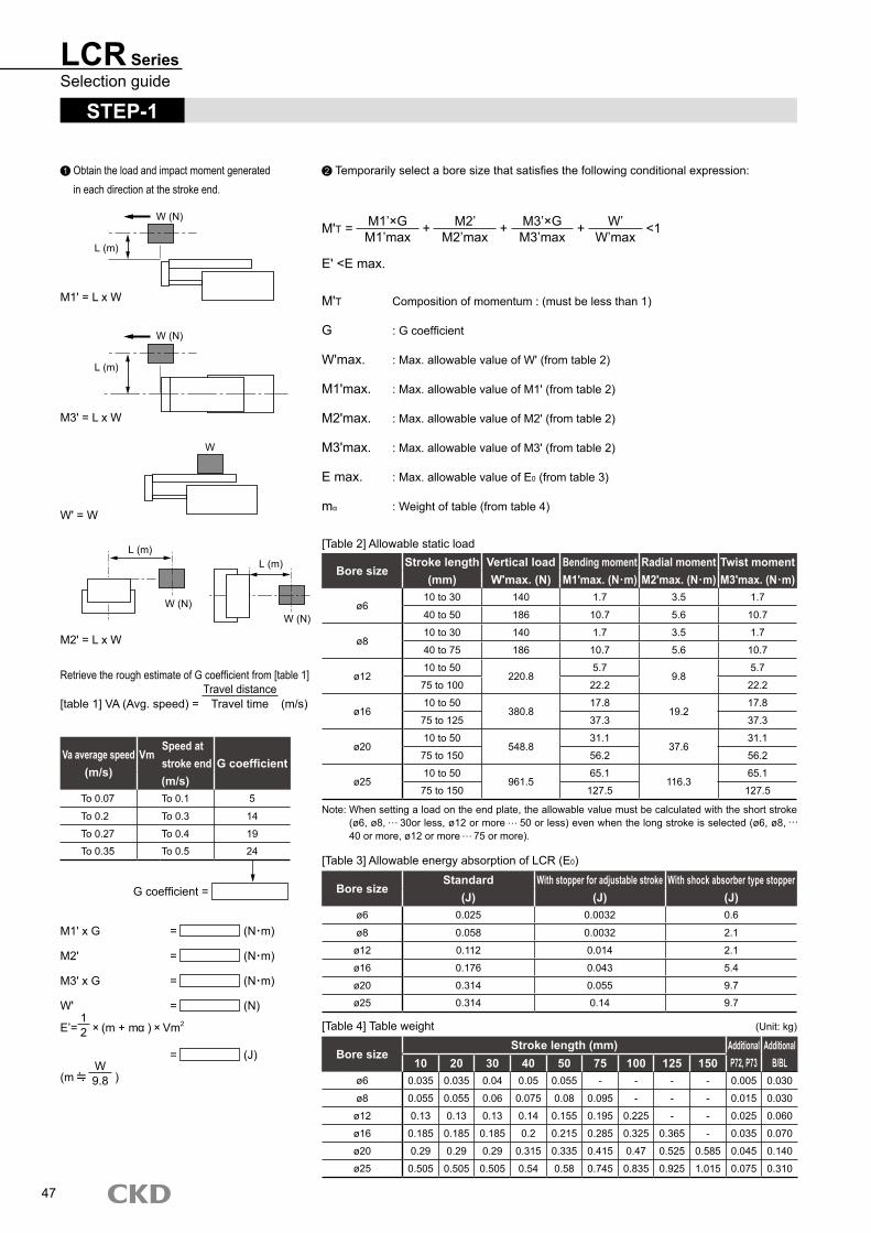
LCR SeriesSelection guide
STEP-1
1 Obtain the load and impact moment generated in each direction at the stroke end.
2 ��Temporarily�select�a�bore�size�that�satisfies�the�following�conditional�expression:
M'T = M1’×GM1’max
+ M2’M2’max
+ M3’×GM3’max
+ W’
W’max <1
E'�<E�max.
M'T Composition�of�momentum�:�(must�be�less�than�1)
G :�G�coefficient
W'max.� :�Max.�allowable�value�of�W'�(from�table�2)
M1'max.� :�Max.�allowable�value�of�M1'�(from�table�2)
M2'max.� :�Max.�allowable�value�of�M2'�(from�table�2)
M3'max.� :�Max.�allowable�value�of�M3'�(from�table�2)
E�max.� :�Max.�allowable�value�of�E0�(from�table�3)
mα :�Weight�of�table�(from�table�4)
M1'�=�L�x�W
M3'�=�L�x�W
W' = W
M2'�=�L�x�W
Retrieve�the�rough�estimate�of�G�coefficient�from�[table�1]
[table�1]�VA�(Avg.�speed)�=�Travel�distanceTravel�time �(m/s)
Va average speed (m/s)
VmSpeed at stroke end G coefficient(m/s)
To 0.07 To 0.1 5
To 0.2 To 0.3 14
To 0.27 To�0.4 19
To 0.35 To 0.5 24
G�coefficient�=�
M1'�x�G� =� �(N m)
M2' = �(N m)�
M3'�x�G� =� �(N m)
W' = �(N)
E’=12
(m�+�m �)� �Vm2
= �(J)
(m� W9.8 �)
[Table�2]�Allowable�static�load
Bore sizeStroke length Vertical load Bending moment Radial moment Twist moment
(mm) W'max. (N) M1'max. (N m) M2'max. (N m) M3'max. (N m)
ø610 to 30 140 1.7 3.5 1.7
40�to�50 186 10.7 5.6 10.7
ø810 to 30 140 1.7 3.5 1.7
40�to�75 186 10.7 5.6 10.7
ø1210 to 50
220.85.7
9.85.7
75 to 100 22.2 22.2
ø1610 to 50
380.817.8
19.217.8
75 to 125 37.3 37.3
ø2010 to 50
548.831.1
37.631.1
75 to 150 56.2 56.2
ø2510 to 50
961.565.1
116.365.1
75 to 150 127.5 127.5
[Table�3]�Allowable�energy�absorption�of�LCR�(E0)
Bore sizeStandard With stopper for adjustable stroke With shock absorber type stopper
(J) (J) (J)ø6 0.025 0.0032 0.6
ø8 0.058 0.0032 2.1
ø12 0.112 0.014 2.1
ø16 0.176 0.043 5.4
ø20 0.314 0.055 9.7
ø25 0.314 0.14 9.7
[Table�4]�Table�weight� (Unit:�kg)
Bore sizeStroke length (mm) Additional
P72, P73Additional
B/BL10 20 30 40 50 75 100 125 150ø6 0.035 0.035 0.04 0.05 0.055 - - - - 0.005 0.030
ø8 0.055 0.055 0.06 0.075 0.08 0.095 - - - 0.015 0.030
ø12 0.13 0.13 0.13 0.14 0.155 0.195 0.225 - - 0.025 0.060
ø16 0.185 0.185 0.185 0.2 0.215 0.285 0.325 0.365 - 0.035 0.070
ø20 0.29 0.29 0.29 0.315 0.335 0.415 0.47 0.525 0.585 0.045 0.140
ø25 0.505 0.505 0.505 0.54 0.58 0.745 0.835 0.925 1.015 0.075 0.310
Note:��When�setting�a�load�on�the�end�plate,�the�allowable�value�must�be�calculated�with�the�short�stroke�(ø6,�ø8,� �30or�less,�ø12�or�more� �50�or�less)�even�when�the�long�stroke�is�selected�(ø6,�ø8,� 40�or�more,�ø12�or�more� �75�or�more).
47
W�(N)
L�(m)
W�(N)
L�(m)
W
W�(N)
L�(m)
W�(N)
L�(m)

LCR SeriesSelection guide
STEP-2
Then�increase�accuracy�of�load�factor,�effective�thrust,�speed at stroke end and composite moment.
At horizontal operation At vertical operationF0 = FW F0 = W+FW
FW:�W�x�0.2�note�(N)W:�load�(N)
[Table�5]�Theoretical�thrust�table� (Unit:�N)
Bore sizeOperating direction
Working pressure MPa(mm) 0.15 0.2 0.3 0.4 0.5 0.6 0.7
ø6PUSH 8 11 17 23 28 34 40
PULL 6 8 13 17 21 25 30
ø8PUSH 15 20 30 40 50 60 70
PULL 11 15 23 30 38 45 53
ø12PUSH 34 45 68 90 113 136 158
PULL 25 34 51 68 85 102 119
ø16PUSH 60 80 121 161 201 241 281
PULL 52 69 104 138 173 207 242
ø20PUSH 94 126 188 251 314 377 440
PULL 79 106 158 211 264 317 369
ø25PUSH 147 196 295 393 491 589 687
PULL 124 165 247 330 412 495 577
�Find�load�factor.
= F0
F�����x�100�(%)
� :�Load�factor
F0�:��Force�required�to�move�a�work�piece�(N)
F� :��Cylinder�theoretical�thrust�(N)�[table�5]
Note:�Coefficient�of�friction
Working pressure MPa Load factor (%)0.2 to 0.3 �40
0.3 to 0.6 50
0.6 to 0.7 60
[Table�6]�Estimated�load�factor
STEP-3
Obtain�the�speed�at�stroke�end�(Vm)�and�G�coefficient�with�average�speed)�Va�and�load�factor�found�at�STEP-2�
Arrow�in� the�figure�(→)�shows�an�example�to�obtain�[speed�at�stroke�end:� 0.35m/s]� and� [G�coefficient:� 16.8]� at� average�speed:� 0 .20m/s� and� load�factor:�50%.
48
Average�speed�Va
�(m/s)
G�coefficient
0.5
0.4
0.3
0.2
0.1
0
5
10
15
20
25
0.1 0.2 0.3 0.4 0.5
Graph�of�speed-G�coefficientG�coefficient�=�
Load�factor�10%
Load�factor�20%
Load�factor�30%Load�factor�40%Load�factor�50%Load�factor�60%
Speed�at�stroke�end�Vm
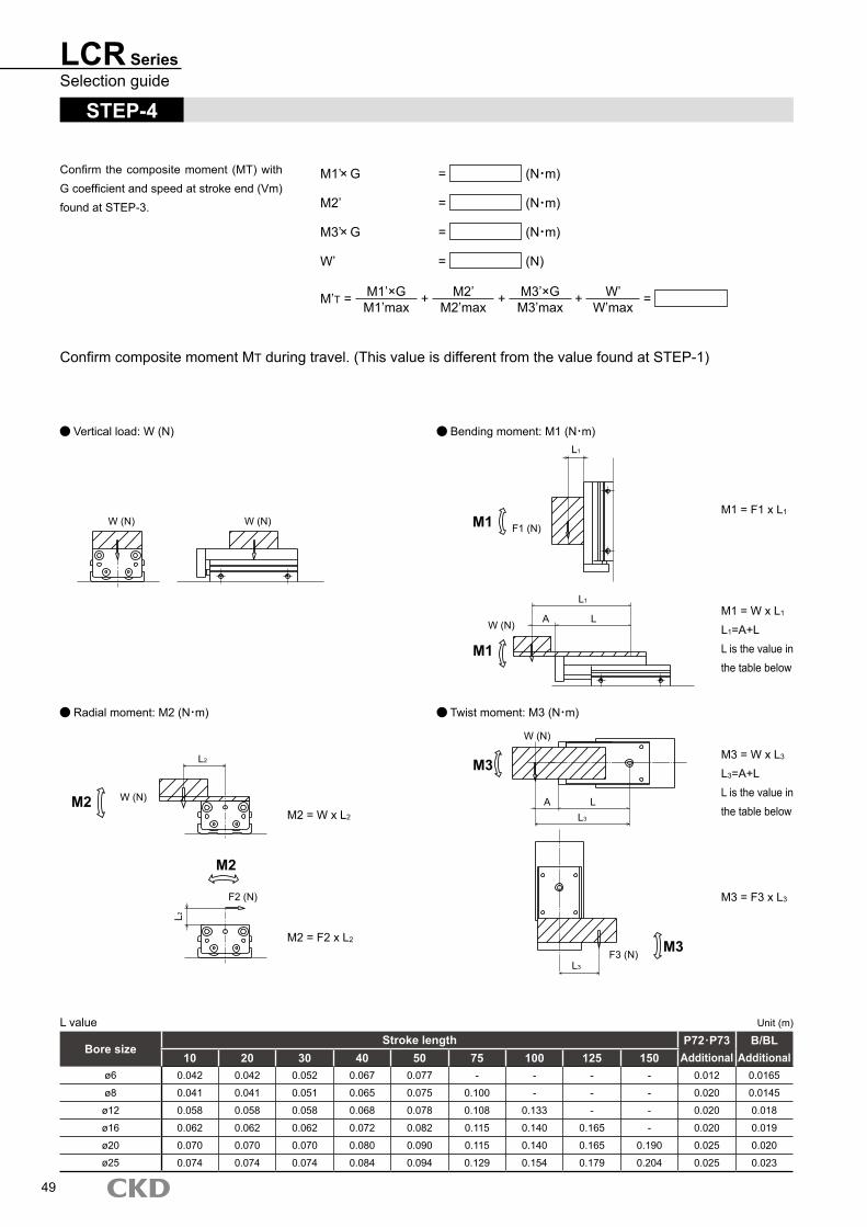
LCR SeriesSelection guide
STEP-4
Confirm�the�composite�moment�(MT)�with�G�coefficient�and�speed�at�stroke�end�(Vm)�found�at�STEP-3.
M1’ G = (N m)
M2’ = (N m)
M3’ G = (N m)
W’ = (N)
M’T = M1’×GM1’max
+ M2’M2’max
+ M3’×GM3’max
+ W’W’max
=
Confirm�composite�moment�MT�during�travel.�(This�value�is�different�from�the�value�found�at�STEP-1)
�Vertical�load:�W�(N)� �Bending�moment:�M1�(N m)
�Radial�moment:�M2�(N m)� �Twist�moment:�M3�(N m)
Bore sizeStroke length P72 P73 B/BL
10 20 30 40 50 75 100 125 150 Additional Additionalø6 0.042 0.042 0.052 0.067 0.077 - - - - 0.012 0.0165
ø8 0.041 0.041 0.051 0.065 0.075 0.100 - - - 0.020 0.0145
ø12 0.058 0.058 0.058 0.068 0.078 0.108 0.133 - - 0.020 0.018
ø16 0.062 0.062 0.062 0.072 0.082 0.115 0.140 0.165 - 0.020 0.019
ø20 0.070 0.070 0.070 0.080 0.090 0.115 0.140 0.165 0.190 0.025 0.020
ø25 0.074 0.074 0.074 0.084 0.094 0.129 0.154 0.179 0.204 0.025 0.023
L�value� Unit�(m)
49
W�(N) W�(N)
W�(N)
L2
L2
F2�(N)
M2
M2
L1
M1 F1�(N)
L1
LAW�(N)
M1
M3
W�(N)
LAL3
M3F3�(N)L3
M2�=�W�x�L2
M2�=�F2�x�L2
M1�=�F1�x�L1
M1�=�W�x�L1
L1=A+LL�is�the�value�in�the�table�below
M3�=�W�x�L3
L3=A+LL�is�the�value�in�the�table�below
M3�=�F3�x�L3

LCR SeriesSelection guide
M1=M1 = (N m)
M2=M2 = (N m)
M3=M3 = (N m)
W=W = (N)
MT = M1M1max
+ M2M2max
+ M3M3max
+ WWmax
=
MT :�Composite�of�moment
Wmax� :�Max.�allowable�value�of�W�(table�7)
M1max� :�Max.�allowable�value�of�M1�(table�7)
M2max� :�Max.�allowable�value�of�M2�(table�7)
M3max� :�Max.�allowable�value�of�M3�(table�7)
E�max.� :�Max.�allowable�value�of�E0�(table�3)
[Table�7]�allowable�traveling�load�value
Bore sizeStroke length Vertical load Bending moment Radial moment Twist moment
(mm) Wmax. (N) M1max. (N m) M2max. (N m) M3max. (N m)
ø610 to 30 14 0.17 0.35 0.17
40�to�50 15.5 0.89 0.47 0.89
ø810 to 30 14 0.17 0.35 0.17
40�to�75 15.5 0.89 0.47 0.89
ø1210 to 50
27.60.71
1.20.71
75 to 100 2.2 2.2
ø1610 to 50
47.61.9
2.41.9
75 to 125 4.6 4.6
ø2010 to 50
68.63.4
4.73.4
75 to 150 7.0 7.0
ø2510 to 50
128.27.6
15.57.6
75 to 150 17.0 17.0
Confirm�that�MT,�M'T 1.
Determining bore size
øA
STEP-5
Confirming�allowable�energy�absorption
E = 12�×�(m�+�mα)�×�Vm2
E :�Kinetic�energy�at�workpiece�end�(J)
m :�Load�weight�(kg)�(is�m� W�(N)
9.8 �)
m α :�Weight�of�table�(from�table�4)
Vm� :�Speed�at�stroke�end�(m/s)
E�max.� :�Max.�allowable�of�E0�(table�3)
Confirm�that�E� �E�max.
Determining bore size
øB
STEP-6
Bore size determined according to STEP-4�(load�conditions)
øA
Bore size determined according to STEP-5�(allowable�energy�consumption)
øB
øA� øB
øA�>�øB
øB
øA
øAor
should be selected
can�be�selected�if�a�shock��absorber�type stopper is used together.
should be selected
Note:��When�setting�a�load�on�the�end�plate,�the�allowable�value�must�be�calculated�with�the�short�stroke�(ø6,�ø8,� �30or�less,�ø12�or�more� �50�or�less)�even�when�the�long�stroke�is�selected�(ø6,�ø8,� 40�or�more,�ø12�or�more� �75�or�more).
50
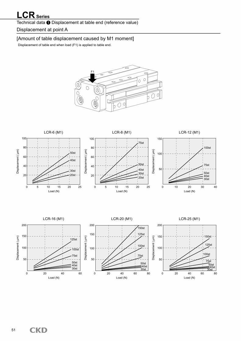
LCR SeriesTechnical data 1 �Displacement�at�table�end�(reference�value)Displacement�at�point�A
[Amount�of�table�displacement�caused�by�M1�moment]Displacement�of�table�end�when�load�(F1)�is�applied�to�table�end.
LCR-6�(M1) LCR-8�(M1) LCR-12�(M1)
LCR-16�(M1) LCR-20�(M1) LCR-25�(M1)
51
F1
Displacem
ent�(�m)
60
40
20
0 5 10 15 20Load�(N)
50st
30st20st
Displacem
ent�(�m)
100
80
60
40
20
0 5 10 15 20 25Load�(N)
75st
40st30st20st
Displacem
ent�(�m)
Load�(N)
150
100
50
0 10 20 30 40
100st
75st
50st40st
Displacem
ent�(�m)
0 20Load�(N)
100
150
200
50
125st
100st
50st40st30st
Displacem
ent�(�m)
0 20Load�(N)
50
100
150
200
60 80
150st
125st
100st
75st
Displacem
ent�(�m)
0 20Load�(N)
50
100
150
200
40 60 80
150st
125st
100st
30st
25
80
100
40st50st
30st
75st
40 60
50st
30st40st
75st50st40st
40
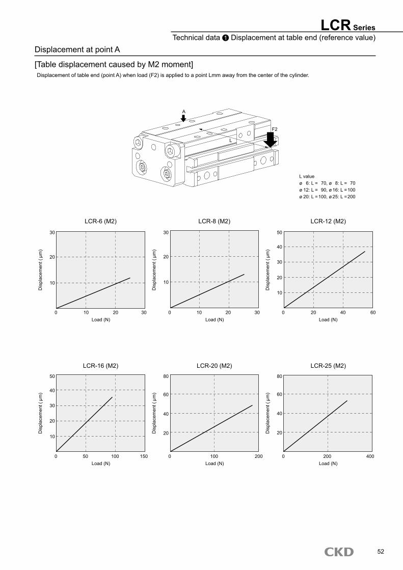
LCR-6�(M2) LCR-8�(M2) LCR-12�(M2)
LCR-16�(M2) LCR-20�(M2) LCR-25�(M2)
Displacement�at�point�A
[Table�displacement�caused�by�M2�moment]Displacement�of�table�end�(point�A)�when�load�(F2)�is�applied�to�a�point�Lmm�away�from�the�center�of�the�cylinder.
LCR SeriesTechnical data 1 �Displacement�at�table�end�(reference�value)
L�valueø� 6:�L�=� 70,�ø� 8:�L�=� 70ø�12:�L�=� 90,�ø�16:�L�=�100ø�20:�L�=�100,�ø�25:�L�=�200
52
A
F2
Displacem
ent�(�m)
Load�(N)
10
0
20
30
10 20 30
Displacem
ent�(�m)
Load�(N)0
10
20
30
10 20 30
Displacem
ent�(�m)
Load�(N)
10
0
20
50
20 60
Displacem
ent�(�m)
Load�(N)
10
0
Displacem
ent�(�m)
Load�(N)
20
0
Displacem
ent�(�m)
Load�(N)
20
0
20
30
50
50 100 150
40
60
80
100 200
40
60
80
200 400
L
30
40
40
40
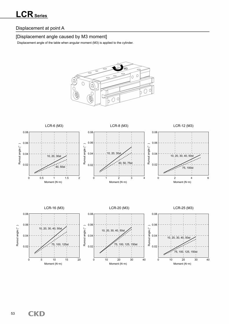
Displacement�at�point�A
[Displacement�angle�caused�by�M3�moment]Displacement�angle�of�the�table�when�angular�moment�(M3)�is�applied�to�the�cylinder.
LCR Series
LCR-6�(M3) LCR-8�(M3) LCR-12�(M3)
LCR-16�(M3) LCR-20�(M3) LCR-25�(M3)
53
M3
Runout�angle�(°��)
Moment�(N m)0
0.02
0.04
0.06
0.08
0.5 1 1.5 2
Runout�angle�(°��)
Moment�(N m)0
0.02
0.04
0.06
0.08
1 2 3 4
Runout�angle�(°��)
Moment�(N m)0
0.02
0.04
0.06
0.08
2 4 6
Runout�angle�(°��)
Moment�(N m)0
Runout�angle�(°��)
Moment�(N m)0
Runout�angle�(°��)
Moment�(N m)05 10 15 20 10 20 30 40 10 20 30 40
10,�20,�30st
40,�50st
10,�20,�30,�40,�50st
75,�100st
10,�20,�30st
40,�50,�75st
10,�20,�30,�40,�50st
75,�100,�125st
10,�20,�30,�40,�50st
75,�100,�125,�150st
10,�20,�30,�40,�50st
75,�100,�125,�150st
0.02
0.04
0.06
0.08
0.02
0.04
0.06
0.08
0.02
0.04
0.06
0.08

54
M E M OM E M O

Contents revised Partial correction of dimensions