Embed Size (px)
Citation preview

THE HASHEMITE KINGDOM OF JORDAN MINISTRY OF WATER AND IRRIGATION (MWI) WATER AUTHORITY OF JORDAN (WAJ) YARMOUK WATER COMPANY (YWC)
THE STUDY FOR BASIC/DETAILED DESIGN AND DRAFT BIDDING DOCUMENTS (COMPONENT B)
UNDER THE PROJECT FOR THE STUDY ON WATER SECTOR FOR
THE HOST COMMUNITIES OF SYRIAN REFUGEES IN NORTHERN GOVERNORATES
IN THE HASHEMITE KINGDOM OF JORDAN
DRAFT BIDDING DOCUMENTS
(5/6)
MARCH 2017
JAPAN INTERNATIONAL COOPERATION AGENCY TEC INTERNATIONAL CO., LTD., JAPAN
IN ASSOCIATION WITH ARABTECH JARDANEH, JORDAN

B I D D I N G D O C U M E N T S
for
Procurement of Construction of Drinking Water
Distribution Pipelines including DMA formation in Irbid City and Suburbs
(Package 3)
Vol. I, II and III
ICB No: [insert ICB number]
Project: [insert name of Project]
Employer: Water Authority of Jordan
Country: The Hashemite Kingdom of Jordan
Issued on: [insert date]


The Entire Bidding Documents are arranged in the following four volumes.
Vol. I: Bidding Procedures, Work
Requirements and Conditions of Contract
Vol. II: Technical Specifications Vol. III: Bill of Quantities Vol. IV: Drawings

Vol. I: Bidding Procedures, Work Requirements and Conditions of Contract


1
Table of Contents
PART 1 – Bidding Procedures ............................................................................................... 2 Section I. Instructions to Bidders ............................................................................... 3 Section II. Bid Data Sheet ........................................................................................ 26 Section III. Evaluation and Qualification Criteria ................................................... 30 Section IV. Bidding Forms ...................................................................................... 46 Section V. Eligibility Criteria and Social and Environmental Responsibility ......... 77 Section VI. Agency Policy - Corrupt and Fraudulent Practices ................................. 79
PART 2 –Works Requirements ........................................................................................... 81 Section VII. Works Requirements ........................................................................... 82
PART 3 – Conditions of Contract and Contract Forms ................................................... 88 Section VIII. General Conditions (GC) ................................................................... 89 Section IX. Particular Conditions (PC) .................................................................. 202 Section X. Contract Forms ..................................................................................... 211

2
PART 1 – BIDDING PROCEDURES
Section I. Instructions to Bidders 3
Section I. Instructions to Bidders
Table of Clauses A. General ......................................................................................................................... 5
1. Scope of Bid ...................................................................................................... 5 2. Source of Funds ................................................................................................ 5 3. Corrupt and Fraudulent Practices ...................................................................... 5 4. Eligible Bidders ................................................................................................ 5 5. Eligible Materials, Equipment, and Services .................................................... 7
B. Contents of Bidding Documents ................................................................................ 7 6. Sections of Bidding Documents ........................................................................ 7 7. Clarification of Bidding Documents, Site Visit, Pre-Bid Meeting ................... 8 8. Amendment of Bidding Documents ................................................................. 9
C. Preparation of Bids ................................................................................................... 10 9. Cost of Bidding ............................................................................................... 10 10. Language of Bid .............................................................................................. 10 11. Documents Comprising the Bid ...................................................................... 10 12. Letter of Bid, Statement of Integrity and Schedules ....................................... 11 13. Alternative Bids .............................................................................................. 11 14. Bid Prices and Discounts ................................................................................ 11 15. Currencies of Bid and Payment ...................................................................... 12 16. Documents Comprising the Technical Proposal ............................................. 13 17. Documents Establishing the Qualifications of the Bidder .............................. 13 18. Period of Validity of Bids ............................................................................... 14 19. Bid Security .................................................................................................... 14 20. Format and Signing of Bid .............................................................................. 16
D. Submission and Opening of Bids ............................................................................. 16 21. Sealing and Marking of Bids .......................................................................... 16 22. Deadline for Submission of Bids .................................................................... 17 23. Late Bids ......................................................................................................... 17 24. Withdrawal, Substitution, and Modification of Bids ...................................... 17 25. Bid Opening .................................................................................................... 18
E. Evaluation and Comparison of Bids ....................................................................... 19 26. Confidentiality ................................................................................................ 19 27. Clarification of Bids ........................................................................................ 19 28. Deviations, Reservations, and Omissions ....................................................... 20 29. Determination of Responsiveness ................................................................... 20 30. Nonmaterial Nonconformities ........................................................................ 21 31. Correction of Arithmetical Errors ................................................................... 21 32. Conversion to Single Currency ....................................................................... 22 33. Margin of Preference ...................................................................................... 22 34. Subcontractors ................................................................................................. 22 35. Evaluation of Bids ........................................................................................... 22 36. Comparison of Bids ........................................................................................ 23

4 Section I. Instructions to Bidders
37. Qualification of the Bidder ..............................................................................23 38. Employer’s Right to Accept Any Bid, and to Reject Any or All Bids ............24
F. Award of Contract .....................................................................................................24 39. Award Criteria .................................................................................................24 40. Notification of Award ......................................................................................24 41. Signing of Contract ..........................................................................................24 42. Performance Security .......................................................................................25
Section I. Instructions to Bidders 5
Section I. Instructions to Bidders
A. General
1. Scope of Bid 1.1 In connection with the Invitation for Bids specified in the Bid Data Sheet (BDS), the Employer, as specified in the BDS, issues these Bidding Documents for the procurement of Works as specified in Section VII, Works Requirements. The name, identification, and number of lots (contracts) of this International Competitive Bidding (ICB) process are specified in the BDS.
1.2 Throughout these Bidding Documents:
(a) the term “in writing” means communicated in written form and delivered against receipt;
(b) except where the context requires otherwise, words indicating the singular also include the plural and words indicating the plural also include the singular; and
(c) “day” means calendar day. 2. Source of Funds 2.1 The Employer specified in the BDS has received or has
applied for financing (hereinafter called “funds”) from the Agence Française de Développement, European Union and the KFW Development Bank (hereinafter called “the Agency”) toward the project named in the BDS. The Employer intends to apply a portion of the funds to eligible payments under the contract(s) for which these Bidding Documents are issued.
3. Corrupt and Fraudulent Practices
3.1 The Agency requires compliance with its policy in regard to corrupt and fraudulent practices as set forth in Section VI.
3.2 In further pursuance of this policy, Bidders shall permit and shall cause its agents (whether declared or not), sub-contractors, sub-consultants, service providers, or suppliers and any personnel thereof, to permit the Agency to inspect all accounts, records and other documents relating to any prequalification process, bid submission, and contract performance (in the case of award), and to have them audited by auditors appointed by the Agency.
4. Eligible Bidders 4.1 A Bidder may be a firm that is a private entity, a government-owned entity—subject to ITB 4.3—or any combination of such entities in the form of a joint venture

6 Section I. Instructions to Bidders
(JV) under an existing agreement or with the intent to enter into such an agreement supported by a letter of intent. In the case of a joint venture, all members shall be jointly and severally liable for the execution of the Contract in accordance with the Contract terms. The JV shall nominate a Representative who shall have the authority to conduct all business for and on behalf of any and all the members of the JV during the bidding process and, in the event the JV is awarded the Contract, during contract execution. Unless specified in the BDS, there is no limit on the number of members in a JV.
4.2 A Bidder shall not have a conflict of interest. Any Bidder found to have a conflict of interest shall be disqualified. A Bidder may be considered to have a conflict of interest for the purpose of this bidding process, if the Bidder:
(a) directly or indirectly controls, is controlled by or is under common control with another Bidder; or
(b) receives or has received any direct or indirect subsidy from another Bidder; or
(c) has the same legal representative as another Bidder; or (d) has a relationship with another Bidder, directly or
through common third parties, that puts it in a position to influence the bid of another Bidder, or influence the decisions of the Employer regarding this bidding process; or
(e) participates in more than one bid in this bidding process. Participation by a Bidder in more than one Bid will result in the disqualification of all Bids in which such Bidder is involved. However, this does not limit the inclusion of the same subcontractor in more than one bid; or
(f) any of its affiliates participated as a consultant in the preparation of the design or technical specifications of the works that are the subject of the bid; or
(g) any of its affiliates has been hired (or is proposed to be hired) by the Employer as Engineer for the Contract implementation; or
(h) has a close business or family relationship with a professional staff of the Employer (or of the project implementing agency, or of a recipient of a part of the loan) who: (i) are directly or indirectly involved in the preparation of the bidding documents or specifications of the contract, and/or the bid evaluation process of
Section I. Instructions to Bidders 7
such contract; or (ii) would be involved in the implementation or supervision of such contract unless the conflict stemming from such relationship has been resolved in a manner acceptable to the Agency throughout the procurement process and execution of the contract.
4.3 The Agency’s eligibility criteria to bid are described in Section V – Eligibility criteria and social and environmental responsibility.
4.4 A Bidder shall not be under suspension from bidding by the Employer as the result of the operation of a Bid–Securing Declaration.
4.5 This bidding is open only to prequalified Bidders unless specified in the BDS.
4.6 A Bidder shall provide such evidence of eligibility satisfactory to the Employer, as the Employer shall reasonably request.
5. Eligible Materials, Equipment, and Services
The materials, equipment and services to be supplied under the Contract and financed by the Agency may have their origin in any country subject to the restrictions specified in Section V, Eligibility criteria and social and environmental responsibility, and all expenditures under the Contract will not contravene such restrictions. At the Employer’s request, Bidders may be required to provide evidence of the origin of materials, equipment and services.
B. Contents of Bidding Documents
6. Sections of Bidding Documents
6.1 The Bidding Documents consist of Parts 1, 2, and 3, which include all the Sections specified below, and which should be read in conjunction with any Addenda issued in accordance with ITB 8.
PART 1 Bidding Procedures
Section I. Instructions to Bidders (ITB) Section II. Bid Data Sheet (BDS) Section III. Evaluation and Qualification Criteria Section IV. Bidding Forms Section V. Eligibility criteria and social and
environmental responsibility
Section VI. Agency Policy-Corrupt and Fraudulent Practices
8 Section I. Instructions to Bidders
PART 2 Works Requirements
Section VII. Works Requirements PART 3 Conditions of Contract and Contract Forms
Section VIII. General Conditions (GC) Section IX. Particular Conditions (PC) Section X. Contract Forms
6.2 The Invitation for Bids issued by the Employer is not part of the Bidding Documents.
6.3 Unless obtained directly from the Employer, the Employer is not responsible for the completeness of the Bidding Documents, responses to requests for clarification, the minutes of the pre-Bid meeting (if any), or Addenda to the Bidding Documents in accordance with ITB 8. In case of any contradiction, documents obtained directly from the Employer shall prevail.
6.4 The Bidder is expected to examine all instructions, forms, terms, and specifications in the Bidding Documents and to furnish with its bid all information and documentation as is required by the Bidding Documents.
7. Clarification of Bidding Documents, Site Visit, Pre-Bid Meeting
7.1 A Bidder requiring any clarification of the Bidding Documents shall contact the Employer in writing at the Employer’s address specified in the BDS or raise its enquiries during the pre-bid meeting if provided for in accordance with ITB 7.4. The Employer will respond in writing to any request for clarification, provided that such request is received no later than fourteen (14) days prior to the deadline for submission of bids. The Employer shall forward copies of its response to all Bidders who have acquired the Bidding Documents in accordance with ITB 6.3, including a description of the inquiry but without identifying its source. If so specified in the BDS, the Employer shall also promptly publish its response at the web page identified in the BDS. Should the clarification result in changes to the essential elements of the Bidding Documents, the Employer shall amend the Bidding Documents following the procedure under ITB 8 and ITB 22.2.
7.2 The Bidder is advised to visit and examine the Site of Works and its surroundings and obtain for itself on its own responsibility all information that may be necessary for preparing the bid and entering into a contract for construction of the Works. The costs of visiting the Site shall be at the Bidder’s own expense.
7.3 The Bidder and any of its personnel or agents will be
Section I. Instructions to Bidders 9
granted permission by the Employer to enter upon its premises and lands for the purpose of such visit, but only upon the express condition that the Bidder, its personnel, and agents will release and indemnify the Employer and its personnel and agents from and against all liability in respect thereof, and will be responsible for death or personal injury, loss of or damage to property, and any other loss, damage, costs, and expenses incurred as a result of the inspection.
7.4 If so specified in the BDS, the Bidder’s designated representative is invited to attend a pre-bid meeting. The purpose of the meeting will be to clarify issues and to answer questions on any matter that may be raised at that stage.
7.5 The Bidder is requested, as far as possible, to submit any questions in writing, to reach the Employer not later than one week before the meeting.
7.6 Minutes of the pre-bid meeting, if applicable, including the text of the questions asked by Bidders, without identifying the source, and the responses given, together with any responses prepared after the meeting, will be transmitted promptly to all Bidders who have acquired the Bidding Documents in accordance with ITB 6.3. Any modification to the Bidding Documents that may become necessary as a result of the pre-bid meeting shall be made by the Employer exclusively through the issue of an Addendum pursuant to ITB 8 and not through the minutes of the pre-bid meeting. Nonattendance at the pre-bid meeting will not be a cause for disqualification of a Bidder.
8. Amendment of Bidding Documents
8.1 At any time prior to the deadline for submission of bids, the Employer may amend the Bidding Documents by issuing addenda.
8.2 Any addendum issued shall be part of the Bidding Documents and shall be communicated in writing to all who have obtained the Bidding Documents from the Employer in accordance with ITB 6.3. The Employer shall also promptly publish the addendum on the Employer’s web page in accordance with ITB 7.1.
8.3 To give Bidders reasonable time in which to take an addendum into account in preparing their bids, the Employer may, at its discretion, extend the deadline for the submission of bids, pursuant to ITB 22.2
10 Section I. Instructions to Bidders
C. Preparation of Bids
9. Cost of Bidding 9.1 The Bidder shall bear all costs associated with the preparation and submission of its Bid, and the Employer shall not be responsible or liable for those costs, regardless of the conduct or outcome of the bidding process.
10. Language of Bid 10.1 The Bid, as well as all correspondence and documents relating to the bid exchanged by the Bidder and the Employer, shall be written in the language specified in the BDS. Supporting documents and printed literature that are part of the Bid may be in another language provided they are accompanied by an accurate translation of the relevant passages in the language specified in the BDS, in which case, for purposes of interpretation of the Bid, such translation shall govern.
11. Documents Comprising the Bid
11.1 The Bid shall comprise the following:
(a) Letter of Bid in accordance with ITB 12;
(b) completed schedules as required, including Price Schedules, in accordance with ITB 12 and 14;
(c) Bid Security or Bid-Securing Declaration, in accordance with ITB 19.1;
(d) alternative bids, if permissible, in accordance with ITB 13;
(e) written confirmation authorizing the signatory of the Bid to commit the Bidder, in accordance with ITB 20.2;
(f) Statement of Integrity, Eligibility and Social and Environmental Responsibility duly signed, in accordance with ITB 12;
(g) documentary evidence in accordance with ITB 17 establishing the Bidder’s continued qualified status or, if post-qualification applies, as specified in accordance with ITB 4.5, the Bidder’s qualifications to perform the contract if its Bid is accepted;
(h) Technical Proposal in accordance with ITB 16;
(i) any other document required in the BDS.
11.2 In addition to the requirements under ITB 11.1, bids submitted by a JV shall include a copy of the Joint Venture Agreement entered into by all members. Alternatively, a letter of intent to execute a Joint Venture Agreement in the event of a successful bid shall be signed
Section I. Instructions to Bidders 11
by all members and submitted with the bid, together with a copy of the proposed Agreement.
11.3 The Bidder shall furnish in the Letter of Bid information on commissions and gratuities, if any, paid or to be paid to agents or any other party relating to this Bid.
12. Letter of Bid, Statement of Integrity and Schedules
12.1 The Letter of Bid, the Statement of Integrity and Schedules, including the Bill of Quantities for unit price contracts or the schedule of price in case of lump sum contracts, shall be prepared using the relevant forms furnished in Section IV, Bidding Forms. The Letter of Bid and the Statement of Integrity must be completed without any alterations to the text, and no substitutes shall be accepted except as provided under ITB 20.4. All blank spaces shall be filled in with the information requested.
13. Alternative Bids 13.1 Unless otherwise specified in the BDS, alternative bids shall not be considered.
13.2 When alternative times for completion are explicitly invited, a statement to that effect will be included in the BDS, as will the method of evaluating different times for completion.
13.3 Except as provided under ITB 13.4 below, Bidders wishing to offer technical alternatives to the requirements of the Bidding Documents must first price the Employer’s design as described in the Bidding Documents and shall further provide all information necessary for a complete evaluation of the alternative by the Employer, including drawings, design calculations, technical specifications, breakdown of prices, and proposed construction methodology and other relevant details. Only the technical alternatives, if any, of the lowest evaluated Bidder conforming to the basic technical requirements shall be considered by the Employer.
13.4 When specified in the BDS, Bidders are permitted to submit alternative technical solutions for specified parts of the Works, and such parts will be identified in the BDS, as will the method for their evaluating, and described in Section VII, Works Requirements.
14. Bid Prices and Discounts
14.1 The prices and discounts quoted by the Bidder in the Letter of Bid and in the Schedules shall conform to the requirements specified below.
14.2 The Bidder shall submit a bid for the whole of the Works described in ITB 1.1, by filling in price(s) for all items of
12 Section I. Instructions to Bidders
the works, as identified in Section IV, Bidding Forms. In case of admeasurement contracts, the Bidder shall fill in rates and prices for all items of the Works described in the Bill of Quantities. Items against which no rate or price is entered by the Bidder shall be deemed covered by the rates for other items in the Bill of Quantities and will not be paid for separately by the Employer. An item not listed in the priced Bill of Quantities shall be assumed to be not included in the Bid, and provided that the Bid is determined substantially responsive notwithstanding this omission, the average price of the item quoted by substantially responsive bidders will be added to the bid price and the equivalent total cost of the bid so determined will be used for price comparison.
14.3 The price to be quoted in the Letter of Bid shall be the total price of the Bid, excluding any discounts offered.
14.4 The Bidder shall quote any discounts and the methodology for their application in the Letter of Bid.
14.5 Unless otherwise specified in the BDS and the Contract, the rate(s) and price(s) quoted by the Bidder are subject to adjustment during the performance of the Contract in accordance with the provisions of the Conditions of Contract. In such a case, the Bidder shall furnish the indices and weightings for the price adjustment formulae in the Schedule of Adjustment Data and the Employer may require the Bidder to justify its proposed indices and weightings.
14.6 If so specified in ITB 1.1, bids are being invited for individual lots (contracts) or for any combination of lots (packages). Bidders wishing to offer discounts for the award of more than one Contract shall specify in their bid the price reductions applicable to each package, or alternatively, to individual Contracts within the package. Discounts shall be submitted in accordance with ITB 14.4, provided the bids for all lots (contracts) are opened at the same time.
14.7 Unless otherwise specified in the BDS, all duties, taxes, and other levies payable by the Contractor under the Contract, or for any other cause, as of the date 28 days prior to the deadline for submission of bids, shall be included in the rates and prices and the total Bid Price submitted by the Bidder.
15. Currencies of Bid and Payment
15.1 The currency(ies) of the bid and the currency(ies) of payments shall be as specified in the BDS.
15.2 Bidders may be required by the Employer to justify, to
Section I. Instructions to Bidders 13
the Employer’s satisfaction, their local and foreign currency requirements, and to substantiate that the amounts included in the prices shown in the Schedule of Adjustment Data in the Bid Data Sheet are reasonable, in which case a detailed breakdown of the foreign currency requirements shall be provided by Bidders.
16. Documents Comprising the Technical Proposal
16.1 The Bidder shall furnish a Technical Proposal including a statement of work methods, equipment, personnel, schedule and any other information as stipulated in Section IV – Bidding Forms, in sufficient detail to demonstrate the adequacy of the Bidder’s proposal to meet the work requirements and the completion time.
17. Documents Establishing the Qualifications of the Bidder
17.1 In accordance with Section III, Evaluation and Qualification Criteria, to establish that the Bidder continues to meet the criteria used at the time of prequalification, the Bidder shall provide in the corresponding information sheets included in Section IV, Bidding Forms, updated information on any assessed aspect that changed from that time, or if post-qualification applies as specified in ITB 4.5, the Bidder shall provide the information requested in the corresponding information sheets included in Section IV, Bidding Forms.
17.2 If a margin of preference applies as specified in accordance with ITB 33.1, domestic Bidders, individually or in joint ventures, applying for eligibility for domestic preference shall supply all information required to satisfy the criteria for eligibility specified in accordance with ITB 33.1.
17.3 Any change in the structure or formation of a Bidder after being prequalified and invited to Bid (including, in the case of a JV, any change in the structure or formation of any member thereto) shall be subject to the written approval of the Employer prior to the deadline for submission of Bids. Such approval shall be denied if (i) as a consequence of the change, the Bidder no longer substantially meets the qualification criteria set forth in Section III, Qualification Criteria and Requirements; or (ii) in the opinion of the Employer, the change may result in a substantial reduction in competition. Any such change should be submitted to the Employer not later than fourteen (14) days after the date of the Invitation for Bids.
14 Section I. Instructions to Bidders
18. Period of Validity of Bids
18.1 Bids shall remain valid for the period specified in the BDS after the bid submission deadline date prescribed by the Employer in accordance with ITB 22.1. A bid valid for a shorter period shall be rejected by the Employer as non responsive.
18.2 In exceptional circumstances, prior to the expiration of the bid validity period, the Employer may request Bidders to extend the period of validity of their bids. The request and the responses shall be made in writing. If a bid security is requested in accordance with ITB 19, it shall also be extended for twenty-eight (28) days beyond the deadline of the extended validity period. A Bidder may refuse the request without forfeiting its bid security. A Bidder granting the request shall not be required or permitted to modify its bid, except as provided in ITB 18.3.
18.3 If the award is delayed by a period exceeding fifty-six (56) days beyond the expiry of the initial bid validity, the Contract price shall be determined as follows:
(a) In the case of fixed price contracts, the Contract price shall be the bid price adjusted by the factor specified in the BDS.
(b) In the case of adjustable price contracts, no adjustment shall be made.
(c) In any case, bid evaluation shall be based on the bid price without taking into consideration the applicable correction from those indicated above.
19. Bid Security 19.1 The Bidder shall furnish as part of its bid, either a Bid-Securing Declaration or a bid security as specified in the BDS, in original form and, in the case of a bid security, in the amount and currency specified in the BDS.
19.2 A Bid-Securing Declaration shall use the form included in Section IV, Bidding Forms.
19.3 If a bid security is specified pursuant to ITB 19.1, the bid security shall be a demand guarantee in any of the following forms at the Bidder’s option:
(a) an unconditional guarantee issued by a bank or financial institution (such as an insurance, bonding or surety company);
(b) an irrevocable letter of credit;
Section I. Instructions to Bidders 15
(c) a cashier’s or certified check; or
(d) another security specified in the BDS,
from a reputable source from an eligible country as specified in Section V-Eligibility criteria and social and environmental responsibility. If the unconditional guarantee is issued by a financial institution located outside the Employer’s Country, the issuing financial institution shall have a correspondent financial institution located in the Employer’s Country to make it enforceable. In the case of a bank guarantee, the bid security shall be submitted either using the Bid Security Form included in Section IV, Bidding Forms, or in another substantially similar format approved by the Employer prior to bid submission. The bid security shall be valid for twenty-eight (28) days beyond the original validity period of the bid, or beyond any period of extension if requested under ITB 18.2.
19.4 Any bid not accompanied by a substantially responsive bid security or Bid-Securing Declaration shall be rejected by the Employer as non responsive.
19.5 The bid security of unsuccessful Bidders shall be returned as promptly as possible upon the successful Bidder’s signing the Contract and furnishing the performance security pursuant to ITB 42.
19.6 The bid security of the successful Bidder shall be returned as promptly as possible once the successful Bidder has signed the Contract and furnished the required performance security.
19.7 The bid security may be forfeited or the Bid-Securing Declaration executed:
(a) if a Bidder withdraws its bid during the period of bid validity specified by the Bidder on the Letter of Bid, or any extension thereto provided by the Bidder; or
(b) if the successful Bidder fails to:
(i) sign the Contract in accordance with ITB 41; or
(ii) furnish a performance security in accordance with ITB 42.
19.8 The bid security or the Bid-Securing Declaration of a JV shall be in the name of the JV that submits the bid. If the JV has not been legally constituted into a legally enforceable JV at the time of bidding, the bid security or the Bid-Securing Declaration shall be in the names of all future members as named in the letter of intent referred to
16 Section I. Instructions to Bidders
in ITB 4.1 and ITB 11.2.
19.9 If a bid security is not required in the BDS pursuant to ITB 19.1, and
(a) if a Bidder withdraws its bid during the period of bid validity specified by the Bidder on the Letter of Bid or any extension thereto provided by the Bidder, or
(b) if the successful Bidder fails to sign the Contract in accordance with ITB 41; or furnish a performance security in accordance with ITB 42;
the Employer may, if provided for in the BDS, declare the Bidder ineligible to be awarded a contract by the Employer for a period of time as stated in the BDS.
20. Format and Signing of Bid
20.1 The Bidder shall prepare one original of the documents comprising the bid as described in ITB 11 and clearly mark it “ORIGINAL.” Alternative bids, if permitted in accordance with ITB 13, shall be clearly marked “ALTERNATIVE.” In addition, the Bidder shall submit copies of the bid, in the number specified in the BDS and clearly mark them “COPY.” In the event of any discrepancy between the original and the copies, the original shall prevail.
20.2 The original and all copies of the bid shall be typed or written in indelible ink and shall be signed by a person duly authorized to sign on behalf of the Bidder. This authorization shall consist of a written confirmation as specified in the BDS and shall be attached to the bid. The name and position held by each person signing the authorization must be typed or printed below the signature. All pages of the bid where entries or amendments have been made shall be signed or initialed by the person signing the bid.
20.3 In case the Bidder is a JV, the Bid shall be signed by an authorized representative of the JV on behalf of the JV, and so as to be legally binding on all the members as evidenced by a power of attorney signed by their legally authorized representatives.
20.4 Any inter-lineation, erasures, or overwriting shall be valid only if they are signed or initialed by the person signing the bid.
D. Submission and Opening of Bids
21. Sealing and 21.1 The Bidder shall enclose the original and all copies of the bid, including alternative bids, if permitted in accordance

Section I. Instructions to Bidders 17
Marking of Bids with ITB 13, in separate sealed envelopes, duly marking the envelopes as “ORIGINAL”, “ALTERNATIVE” and “COPY.” These envelopes containing the original and the copies shall then be enclosed in one single envelope.
21.2 The inner and outer envelopes shall:
(a) bear the name and address of the Bidder; (b) be addressed to the Employer in accordance with
ITB 22.1; (c) bear the specific identification of this bidding process
specified in the BDS 1.1; and (d) bear a warning not to open before the time and date for
bid opening.
21.3 If all envelopes are not sealed and marked as required, the Employer will assume no responsibility for the misplacement or premature opening of the bid.
22. Deadline for Submission of Bids
22.1 Bids must be received by the Employer at the address and no later than the date and time specified in the BDS. When so specified in the BDS, bidders shall have the option of submitting their bids electronically. Bidders submitting bids electronically shall follow the electronic bid submission procedures specified in the BDS.
22.2 The Employer may, at its discretion, extend the deadline for the submission of bids by amending the Bidding Documents in accordance with ITB 8, in which case all rights and obligations of the Employer and Bidders previously subject to the deadline shall thereafter be subject to the deadline as extended.
23. Late Bids 23.1 The Employer shall not consider any bid that arrives after the deadline for submission of bids, in accordance with ITB 22. Any bid received by the Employer after the deadline for submission of bids shall be declared late, rejected, and returned unopened to the Bidder.
24. Withdrawal, Substitution, and Modification of Bids
24.1 A Bidder may withdraw, substitute, or modify its bid after it has been submitted by sending a written notice, duly signed by an authorized representative, and shall include a copy of the authorization in accordance with ITB 20.2. The corresponding substitution or modification of the bid must accompany the respective written notice. All notices must be:
(a) prepared and submitted in accordance with ITB 20 and ITB 21 (except that withdrawals notices do not require copies), and in addition, the respective envelopes shall
18 Section I. Instructions to Bidders
be clearly marked “WITHDRAWAL,” “SUBSTITUTION,” “MODIFICATION;” and
(b) received by the Employer prior to the deadline prescribed for submission of bids, in accordance with ITB 22.
24.2 Bids requested to be withdrawn in accordance with ITB 24.1 shall be returned unopened to the Bidders.
24.3 No bid may be withdrawn, substituted, or modified in the interval between the deadline for submission of bids and the expiration of the period of bid validity specified by the Bidder on the Letter of Bid or any extension thereof.
25. Bid Opening 25.1 Except in the cases specified in ITB 23 and 24, the Employer shall publicly open and read out in accordance with ITB 25 all bids received by the deadline (regardless of the number of bids received), at the date, time and place specified in the BDS, in the presence of Bidders` designated representatives and anyone who choose to attend. Any specific electronic bid opening procedures required if electronic bidding is permitted in accordance with ITB 22.1, shall be as specified in the BDS.
25.2 First, envelopes marked “WITHDRAWAL” shall be opened and read out and the envelope with the corresponding bid shall not be opened, but returned to the Bidder. No bid withdrawal shall be permitted unless the corresponding withdrawal notice contains a valid authorization to request the withdrawal and is read out at bid opening. Next, envelopes marked “SUBSTITUTION” shall be opened and read out and exchanged with the corresponding bid being substituted, and the substituted bid shall not be opened, but returned to the Bidder. No bid substitution shall be permitted unless the corresponding substitution notice contains a valid authorization to request the substitution and is read out at bid opening. Envelopes marked “MODIFICATION” shall be opened and read out with the corresponding bid. No bid modification shall be permitted unless the corresponding modification notice contains a valid authorization to request the modification and is read out at bid opening. Only bids that are opened and read out at bid opening shall be considered further.
25.3 All other envelopes shall be opened one at a time, reading out: the name of the Bidder and whether there is a modification; the total Bid Price, per lot (contract) if applicable, including any discounts and alternative bids; the presence or absence of a bid security or bid-securing declaration, if required; and any other details as the Employer may consider appropriate. Only discounts

Section I. Instructions to Bidders 19
and alternative bids read out at bid opening shall be considered for evaluation. The Letter of Bid and the Schedules are to be initialed by a minimum of three representatives of the Employer attending bid opening. The Employer shall neither discuss the merits of any bid nor reject any bid (except for late bids, in accordance with ITB 23.1).
25.4 The Employer shall prepare a record of the bid opening that shall include, as a minimum: the name of the Bidder and whether there is a withdrawal, substitution, or modification; the Bid Price, per lot (contract) if applicable, including any discounts and alternative bids; and the presence or absence of a bid security or bid-securing declaration, if one was required. The Bidders’ representatives who are present shall be requested to sign the record. The omission of a Bidder’s signature on the record shall not invalidate the contents and effect of the record. A copy of the record shall be distributed to all Bidders.
E. Evaluation and Comparison of Bids
26. Confidentiality 26.1 Information relating to the examination, evaluation, and comparison of the bids, and qualification of the Bidders and recommendation of contract award shall not be disclosed to Bidders or any other persons not officially concerned with the bidding process until information on Contract award is communicated to all Bidders in accordance with ITB 40.
26.2 Any attempt by a Bidder to influence the Employer in the examination, evaluation, and comparison of the bids, and qualification of the Bidders, or Contract award decisions may result in the rejection of its bid.
26.3 Notwithstanding ITB 26.2, from the time of bid opening to the time of Contract award, if a Bidder wishes to contact the Employer on any matter related to the bidding process, it shall do so in writing.
27. Clarification of Bids
27.1 To assist in the examination, evaluation, and comparison of the bids, and qualification of the Bidders, the Employer may, at its discretion, ask any Bidder for a clarification of its bid, given a reasonable time for a response. Any clarification submitted by a Bidder that is not in response to a request by the Employer shall not be considered. The Employer’s request for clarification and the response shall be in writing. No change, including any voluntary increase or decrease, in the prices or substance of the bid shall be sought, offered, or
20 Section I. Instructions to Bidders
permitted, except to confirm the correction of arithmetic errors discovered by the Employer in the evaluation of the bids, in accordance with ITB 31.
27.2 If a Bidder does not provide clarifications of its bid by the date and time set in the Employer’s request for clarification, its bid may be rejected.
28. Deviations, Reservations, and Omissions
28.1 During the evaluation of bids, the following definitions apply:
(a) “Deviation” is a departure from the requirements specified in the Bidding Documents;
(b) “Reservation” is the setting of limiting conditions or withholding from complete acceptance of the requirements specified in the Bidding Documents; and
(c) “Omission” is the failure to submit part or all of the information or documentation required in the Bidding Documents.
29. Determination of Responsiveness
29.1 The Employer’s determination of a bid’s responsiveness is to be based on the contents of the bid itself, as defined in ITB11.
29.2 A substantially responsive bid is one that meets the requirements of the Bidding Documents without material deviation, reservation, or omission. A material deviation, reservation, or omission is one that,
(a) if accepted, would:
(i) affect in any substantial way the scope, quality, or performance of the Works specified in the Contract; or
(ii) limit in any substantial way, inconsistent with the Bidding Documents, the Employer’s rights or the Bidder’s obligations under the proposed Contract; or
(b) if rectified, would unfairly affect the competitive position of other Bidders presenting substantially responsive bids.
29.3 The Employer shall examine the technical aspects of the bid submitted in accordance with ITB 16, in particular, to confirm that all requirements of Section VII, Works Requirements have been met without any material deviation, reservation or omission.
29.4 If a bid is not substantially responsive to the requirements of the Bidding Documents, it shall be rejected by the Employer and may not subsequently be made responsive
Section I. Instructions to Bidders 21
by correction of the material deviation, reservation, or omission.
30. Nonmaterial Nonconformities
30.1 Provided that a bid is substantially responsive, the Employer may waive any nonmaterial nonconformities in the Bid.
30.2 Provided that a bid is substantially responsive, the Employer may request that the Bidder submit the necessary information or documentation, within a reasonable period of time, to rectify nonmaterial nonconformities in the bid related to documentation requirements. Requesting information or documentation on such nonconformities shall not be related to any aspect of the price of the Bid. Failure of the Bidder to comply with the request may result in the rejection of its Bid.
30.3 Provided that a bid is substantially responsive, the Employer shall rectify quantifiable nonmaterial nonconformities related to the Bid Price. To this effect, the Bid Price shall be adjusted, for comparison purposes only, to reflect the price of a missing or non-conforming item or component.
31. Correction of Arithmetical Errors
31.1 Provided that the bid is substantially responsive, the Employer shall correct arithmetical errors on the following basis:
(a) Only for admeasurement contracts, if there is a discrepancy between the unit price and the total price that is obtained by multiplying the unit price and quantity, the unit price shall prevail and the total price shall be corrected, unless in the opinion of the Employer there is an obvious misplacement of the decimal point in the unit price, in which case the total price as quoted shall govern and the unit price shall be corrected;
(b) Only for admeasurement contracts, if there is an error in a total corresponding to the addition or subtraction of subtotals, the subtotals shall prevail and the total shall be corrected; and
(c) if there is a discrepancy between words and figures, the amount in words shall prevail, unless, only for admeasurement contracts, the amount expressed in words is related to an arithmetic error, in which case the amount in figures shall prevail subject to (a) and (b) above.
31.2 Bidders shall be requested to accept correction of arithmetical errors. Failure to accept the correction in
22 Section I. Instructions to Bidders
accordance with ITB 31.1, shall result in the rejection of the Bid.
32. Conversion to Single Currency
32.1 For evaluation and comparison purposes, the currency(ies) of the Bid shall be converted into a single currency as specified in the BDS.
33. Margin of Preference
33.1 Unless otherwise specified in the BDS, a margin of preference for domestic bidders1 shall not apply.
34. Subcontractors 34.1 Unless otherwise stated in the BDS, the Employer does not intend to execute any specific elements of the Works by sub-contractors selected in advance by the Employer.
34.2 In case of Prequalification, the Bidder’s Bid shall name the same specialized subcontractor as submitted in the prequalification application and approved by the Employer, or may name another specialized subcontractor meeting the requirements specified in the prequalification phase.
34.3 In case of Postqualification, the Employer may permit subcontracting for certain specialized works as indicated in Section III 4.2 Experience. When subcontracting is permitted by the Employer, the specialized sub-contractor’s experience shall be considered for evaluation. Section III describes the qualification criteria for sub-contractors.
35. Evaluation of Bids 35.1 The Employer shall use the criteria and methodologies listed in this Clause. No other evaluation criteria or methodologies shall be permitted unless otherwise specified in the BDS
35.2 To evaluate a bid, the Employer shall consider the following:
(a) the bid price, excluding Provisional Sums and the provision, if any, for contingencies in the Schedules, but including Daywork items, where priced competitively;
(b) price adjustment for correction of arithmetic errors in accordance with ITB 31.1;
1 An individual firm is considered a domestic bidder for purposes of the margin of preference if it is registered in the
country of the Employer, has more than 50 percent ownership by nationals of the country of the Employer, and if it does not subcontract more than 30 percent of the contract price, excluding provisional sums, to foreign contractors. JVs are considered as domestic bidders and eligible for domestic preference only if the individual member firms are registered in the country of the Employer, have more than 50 percent ownership by nationals of the country of the Employer, and the JV shall be registered in the country of the Borrower. The JV shall not subcontract more than 30 percent of the contract price, excluding provisional sums, to foreign firms. JVs between foreign and national firms will not be eligible for domestic preference.
Section I. Instructions to Bidders 23
(c) price adjustment due to discounts offered in accordance with ITB 14.4;
(d) converting the amount resulting from applying (a) to (c) above, if relevant, to a single currency in accordance with ITB 32;
(e) price adjustment due to quantifiable nonmaterial nonconformities in accordance with ITB 30.3;
(f) the additional evaluation factors as specified in Section III, Evaluation and Qualification Criteria.
35.3 The estimated effect of the price adjustment provisions of the Conditions of Contract, applied over the period of execution of the Contract, shall not be taken into account in bid evaluation.
35.4 If these Bidding Documents allows Bidders to quote separate prices for different lots (contracts), the methodology to determine the lowest evaluated price of the lot (contract) combinations, including any discounts offered in the Letter of Bid Form, is specified in Section III, Evaluation and Qualification Criteria.
35.5 If the bid, which results in the lowest Evaluated Bid Price, is significantly lower than the Employer’s estimate or seriously unbalanced or front loaded in the opinion of the Employer, the Employer may require the Bidder to produce detailed price analyses for any or all items of the Schedules, to demonstrate the internal consistency of those prices with the construction methods and schedule proposed. If it turns out that the bid price is abnormally low, the bid may be declared non compliant and rejected. After evaluation of the price analyses, taking into consideration the schedule of estimated Contract payments, the Employer may require that the amount of the performance security be increased at the expense of the Bidder to a level sufficient to protect the Employer against financial loss in the event of default of the successful Bidder under the Contract.
36. Comparison of Bids
36.1 The Employer shall compare the evaluated prices of all substantially responsive bids established in accordance with ITB 35.2 to determine the lowest evaluated bid .
37. Qualification of the Bidder
37.1 The Employer shall determine to its satisfaction whether the Bidder that is selected as having submitted the lowest evaluated and substantially responsive bid either continues to meet (if prequalification applies) or meets (if postqualification applies) the qualifying criteria specified
24 Section I. Instructions to Bidders
in Section III, Evaluation and Qualification Criteria.
37.2 The determination shall be based upon an examination of the documentary evidence of the Bidder’s qualifications submitted by the Bidder, pursuant to ITB 17.1.
37.3 An affirmative determination shall be a prerequisite for award of the Contract to the Bidder. A negative determination shall result in disqualification of the bid, in which event the Employer shall proceed to the next lowest evaluated bid to make a similar determination of that Bidder’s qualifications to perform satisfactorily.
38. Employer’s Right to Accept Any Bid, and to Reject Any or All Bids
38.1 The Employer reserves the right to accept or reject any bid, and to annul the bidding process and reject all bids at any time prior to contract award, without thereby incurring any liability to Bidders. In case of annulment, all bids submitted and specifically, bid securities, shall be promptly returned to the Bidders.
F. Award of Contract
39. Award Criteria 39.1 Subject to ITB 38.1, the Employer shall award the Contract to the Bidder whose bid has been determined to be the lowest evaluated bid and is substantially responsive to the Bidding Documents, provided further that the Bidder is determined to be qualified to perform the Contract satisfactorily.
40. Notification of Award
40.1 Prior to the expiration of the period of bid validity, the Employer shall notify the successful Bidder, in writing, that its bid has been accepted. The notification letter (hereinafter and in the Conditions of Contract and Contract Forms called the “Letter of Acceptance”) shall specify the sum that the Employer will pay the Contractor in consideration of the execution and completion of the Works (hereinafter and in the Conditions of Contract and Contract Forms called “the Contract Price”) and the requirement for the Contractor to remedy any defects therein. At the same time, the Employer shall also notify all other Bidders of the results of the bidding.
40.2 Until a formal contract is prepared and executed, the notification of award shall constitute a binding Contract.
40.3 The Employer shall promptly respond in writing to any unsuccessful Bidder who, after notification of award in accordance with ITB 40.1, requests in writing the grounds on which its bid was not selected.
41. Signing of 41.1 Promptly upon notification, the Employer shall send the
Section I. Instructions to Bidders 25
Contract successful Bidder the Contract Agreement.
41.2 Within twenty-eight (28) days of receipt of the Contract Agreement, the successful Bidder shall sign, date, and return it to the Employer.
42. Performance Security
42.1 Within twenty-eight (28) days of the receipt of notification of award from the Employer, the successful Bidder shall furnish the performance security in accordance with the General Conditions of Contract, subject to ITB 35.5, using for that purpose the Performance Security Form included in Section X –Contract Forms, or another form acceptable to the Employer. If the performance security furnished by the successful Bidder is in the form of a bond, it shall be issued by a bonding or insurance company that has been determined by the successful Bidder to be acceptable to the Employer. A foreign institution providing a bond shall have a correspondent financial institution located in the Employer’s Country.
42.2 Failure of the successful Bidder to submit the above-mentioned Performance Security or sign the Contract shall constitute sufficient grounds for the annulment of the award and forfeiture of the bid security or execution of the Bid-Securing Declaration. In that event the Employer may award the Contract to the next lowest evaluated Bidder whose offer is substantially responsive and is determined by the Employer to be qualified to perform the Contract satisfactorily.
26 Section II. Bid Data Sheet
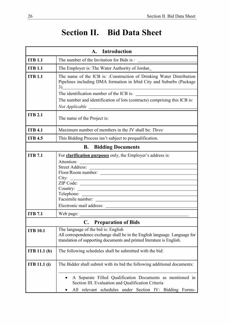
Section II. Bid Data Sheet
A. Introduction ITB 1.1 The number of the Invitation for Bids is :
ITB 1.1 The Employer is: The Water Authority of Jordan
ITB 1.1 The name of the ICB is: :Construction of Drinking Water Distribution Pipelines including DMA formation in Irbid City and Suburbs (Package 3) The identification number of the ICB is: The number and identification of lots (contracts) comprising this ICB is: Not Applicable
ITB 2.1 The name of the Project is:
ITB 4.1 Maximum number of members in the JV shall be: Three
ITB 4.5 This Bidding Process isn’t subject to prequalification.
B. Bidding Documents ITB 7.1 For clarification purposes only, the Employer’s address is:
Attention: Street Address: Floor/Room number: City: ZIP Code: Country: Telephone: Facsimile number: Electronic mail address:
ITB 7.1 Web page: _______________________________________________
C. Preparation of Bids ITB 10.1 The language of the bid is: English
All correspondence exchange shall be in the English language. Language for translation of supporting documents and printed literature is English.
ITB 11.1 (b) The following schedules shall be submitted with the bid:
ITB 11.1 (i) The Bidder shall submit with its bid the following additional documents:
A Separate Filled Qualification Documents as mentioned in Section III. Evaluation and Qualification Criteria
All relevant schedules under Section IV: Bidding Forms-

Section II. Bid Data Sheet 27
“Bidder’s Qualification without prequalification”.
ITB 13.1 Alternative bids shall not be permitted under ITB 13.2, ITB 13.3, or ITB 13.4
ITB 13.2 Alternative times for completion are not permitted.
ITB 13.4 Alternative technical solutions shall be permitted for the following parts of the Works: Not Applicable. If alternative technical solutions are permitted, the evaluation method will be as specified in Section III, Evaluation and Qualification Criteria. Those technical alternatives shall be considered as an acceptable basic technical requirement option and therefore are not subject to ITB 13.3.
ITB 14.5 The prices quoted by the bidder shall not be subject to adjustment.
ITB 14.7 Taxes, duties and fees exemptions, to which payments under the Contract are entitled, are specified in clause 14.1 (b) of the Particular Conditions of Contract.
ITB 15.1 The currency(ies) of the bid and the payment currency(ies) shall be in accordance with the following: (Bidders to quote entirely in local currency): The unit rates and the prices shall be quoted by the Bidder in the Schedules, entirely in Jordanian Dinars, the name of the currency of the Employer’s country, and further referred to as “the local currency”.
ITB 18.1 The bid validity period shall be 120 days.
ITB 18.3 (a) The bid price shall be adjusted as follows will be indicated in the request for bid validity extension.
ITB 19.1
A Bid Security of 3% of the contract price in Jordanian Dinars is required. A Bid-Securing Declaration is required.
ITB 19.3 (d) Other types of acceptable securities: non
ITB 20.1 In addition to the original of the bid, the number of copies is: Two. In addition to this, the bidder shall submit to one soft (digital) copy of each of the technical and financial proposals separately.
ITB 20.2 The written confirmation of authorization to sign on behalf of the Bidder shall consist of a power of attorney established in the name of the signatory of the bid
D. Submission and Opening of Bids ITB 22.1 For bid submission purposes only, the Employer’s address is :
Attention: Street Address: Floor/Room number: City: ZIP Code:
28 Section II. Bid Data Sheet
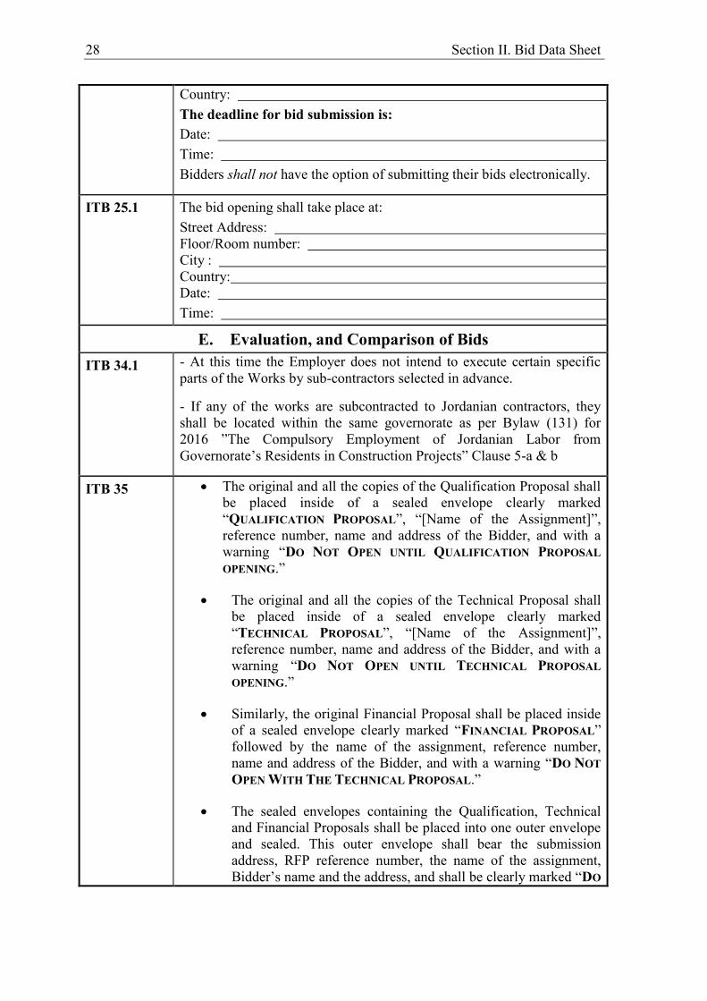
Country: The deadline for bid submission is: Date: Time: Bidders shall not have the option of submitting their bids electronically.
ITB 25.1 The bid opening shall take place at: Street Address: Floor/Room number: City : Country: Date: Time:
E. Evaluation, and Comparison of Bids ITB 34.1 - At this time the Employer does not intend to execute certain specific
parts of the Works by sub-contractors selected in advance.
- If any of the works are subcontracted to Jordanian contractors, they shall be located within the same governorate as per Bylaw (131) for 2016 ”The Compulsory Employment of Jordanian Labor from Governorate’s Residents in Construction Projects” Clause 5-a & b
ITB 35 The original and all the copies of the Qualification Proposal shall be placed inside of a sealed envelope clearly marked “QUALIFICATION PROPOSAL”, “[Name of the Assignment]”, reference number, name and address of the Bidder, and with a warning “DO NOT OPEN UNTIL QUALIFICATION PROPOSAL OPENING.”
The original and all the copies of the Technical Proposal shall be placed inside of a sealed envelope clearly marked “TECHNICAL PROPOSAL”, “[Name of the Assignment]”, reference number, name and address of the Bidder, and with a warning “DO NOT OPEN UNTIL TECHNICAL PROPOSAL OPENING.”
Similarly, the original Financial Proposal shall be placed inside of a sealed envelope clearly marked “FINANCIAL PROPOSAL” followed by the name of the assignment, reference number, name and address of the Bidder, and with a warning “DO NOT OPEN WITH THE TECHNICAL PROPOSAL.”
The sealed envelopes containing the Qualification, Technical and Financial Proposals shall be placed into one outer envelope and sealed. This outer envelope shall bear the submission address, RFP reference number, the name of the assignment, Bidder’s name and the address, and shall be clearly marked “DO

Section II. Bid Data Sheet 29
NOT OPEN BEFORE QUALIFICATION PROPOSAL OPENING”.

30 Section III. Evaluation and Qualification Criteria (without prequalification)
Section III. Evaluation and Qualification Criteria
This Section contains all the criteria that the Employer shall use to evaluate bids and qualify Bidders. In accordance with ITB 35 and ITB 37, no other factors, methods or criteria shall be used. The Bidder shall provide all the information requested in the forms included in Section IV, Bidding Forms. Wherever a Bidder is required to state a monetary amount, Bidders should indicate the amounts in Jordanian Dinars.

Section III. Evaluation and Qualification Criteria (without prequalification) 31
Qualification and Evaluation 1. Evaluation of Qualification, Technical Proposals and financial proposals
The Client’s evaluation committee shall evaluate the Qualification Proposals on the basis of their responsiveness to the Qualification requirements, applying the evaluation criteria, sub-criteria, and systems. Each responsive Proposal will be given a PASS/FAIL score. A Proposal shall be rejected at this stage if it does not respond to Qualification requirements.
If the bid passes the qualification criteria, the Client’s evaluation committee shall evaluate the Technical Proposals on the basis of their responsiveness to the Tender documents, applying the evaluation criteria, sub-criteria, and point system. Each responsive Proposal will be given a technical score. A Proposal shall be rejected at this stage if it does not respond to important aspects of the Tender Documents or if it fails to achieve the minimum technical score of 60%. Technical and financial proposals for tenders that fails to qualify the qualification criteria will be returned sealed to the bidder. Following the ranking of the Technical Proposals, Only the Financial Proposal of the Bidders who score more than 60% score will be opened by the Client’s evaluation committee. All other Financial Proposals will be returned unopened after the Contract negotiations are successfully concluded and the Contract is signed.
In addition to the criteria listed in ITB 35.2 (a) – (e) the following Qualification and Evaluation criteria shall apply:
32 Section III. Evaluation and Qualification Criteria (without prequalification)
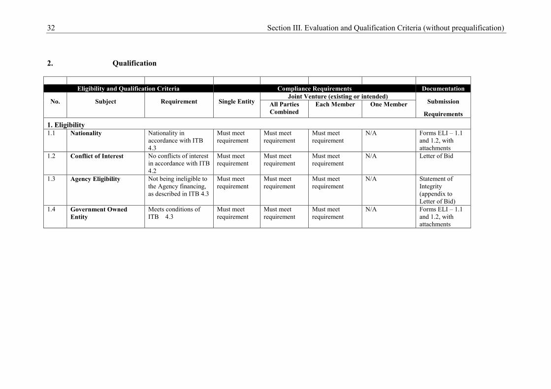
2. Qualification
Eligibility and Qualification Criteria Compliance Requirements Documentation
No. Subject Requirement Single Entity Joint Venture (existing or intended)
Submission
Requirements All Parties Combined
Each Member One Member
1. Eligibility 1.1 Nationality Nationality in
accordance with ITB 4.3
Must meet requirement
Must meet requirement
Must meet requirement
N/A Forms ELI – 1.1 and 1.2, with attachments
1.2 Conflict of Interest No conflicts of interest in accordance with ITB 4.2
Must meet requirement
Must meet requirement
Must meet requirement
N/A Letter of Bid
1.3 Agency Eligibility Not being ineligible to the Agency financing, as described in ITB 4.3
Must meet requirement
Must meet requirement
Must meet requirement
N/A
Statement of Integrity (appendix to Letter of Bid)
1.4 Government Owned Entity
Meets conditions of ITB 4.3
Must meet requirement
Must meet requirement
Must meet requirement
N/A
Forms ELI – 1.1 and 1.2, with attachments
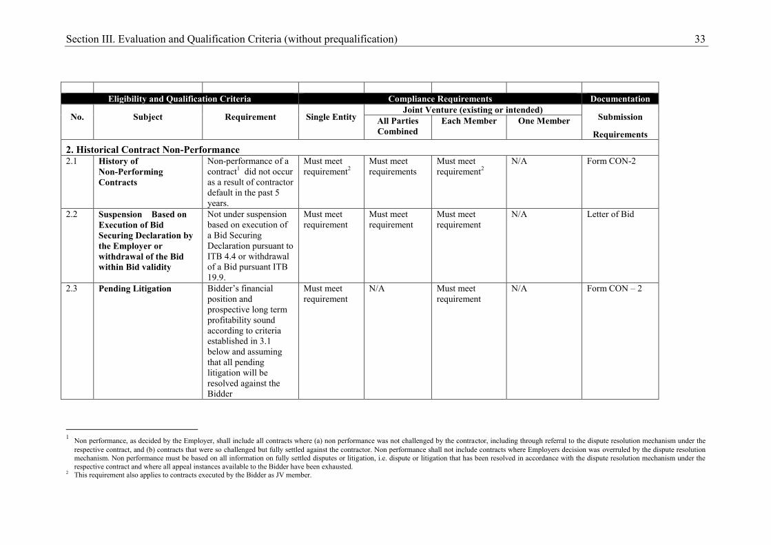
Section III. Evaluation and Qualification Criteria (without prequalification) 33
Eligibility and Qualification Criteria Compliance Requirements Documentation
No. Subject Requirement Single Entity Joint Venture (existing or intended)
Submission
Requirements All Parties Combined
Each Member One Member
2. Historical Contract Non-Performance 2.1 History of
Non-Performing Contracts
Non-performance of a contract1 did not occur as a result of contractor default in the past 5 years.
Must meet requirement2
Must meet requirements
Must meet requirement2
N/A Form CON-2
2.2 Suspension Based on Execution of Bid Securing Declaration by the Employer or withdrawal of the Bid within Bid validity
Not under suspension based on execution of a Bid Securing Declaration pursuant to ITB 4.4 or withdrawal of a Bid pursuant ITB 19.9.
Must meet requirement
Must meet requirement
Must meet requirement
N/A Letter of Bid
2.3 Pending Litigation Bidder’s financial position and prospective long term profitability sound according to criteria established in 3.1 below and assuming that all pending litigation will be resolved against the Bidder
Must meet requirement
N/A Must meet requirement
N/A Form CON – 2
1 Non performance, as decided by the Employer, shall include all contracts where (a) non performance was not challenged by the contractor, including through referral to the dispute resolution mechanism under the
respective contract, and (b) contracts that were so challenged but fully settled against the contractor. Non performance shall not include contracts where Employers decision was overruled by the dispute resolution mechanism. Non performance must be based on all information on fully settled disputes or litigation, i.e. dispute or litigation that has been resolved in accordance with the dispute resolution mechanism under the respective contract and where all appeal instances available to the Bidder have been exhausted.
2 This requirement also applies to contracts executed by the Bidder as JV member.
34 Section III. Evaluation and Qualification Criteria (without prequalification)
Eligibility and Qualification Criteria Compliance Requirements Documentation
No. Subject Requirement Single Entity Joint Venture (existing or intended)
Submission
Requirements All Parties Combined
Each Member One Member
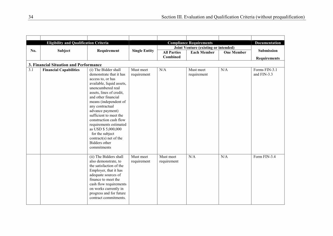
3. Financial Situation and Performance 3.1 Financial Capabilities (i) The Bidder shall
demonstrate that it has access to, or has available, liquid assets, unencumbered real assets, lines of credit, and other financial means (independent of any contractual advance payment) sufficient to meet the construction cash flow requirements estimated as USD $ 5,000,000 for the subject contract(s) net of the Bidders other commitments
Must meet requirement
N/A
Must meet requirement
N/A
Forms FIN-3.1 and FIN-3.3
(ii) The Bidders shall also demonstrate, to the satisfaction of the Employer, that it has adequate sources of finance to meet the cash flow requirements on works currently in progress and for future contract commitments.
Must meet requirement
Must meet requirement
N/A N/A Form FIN-3.4
Section III. Evaluation and Qualification Criteria (without prequalification) 35
Eligibility and Qualification Criteria Compliance Requirements Documentation
No. Subject Requirement Single Entity Joint Venture (existing or intended)
Submission
Requirements All Parties Combined
Each Member One Member
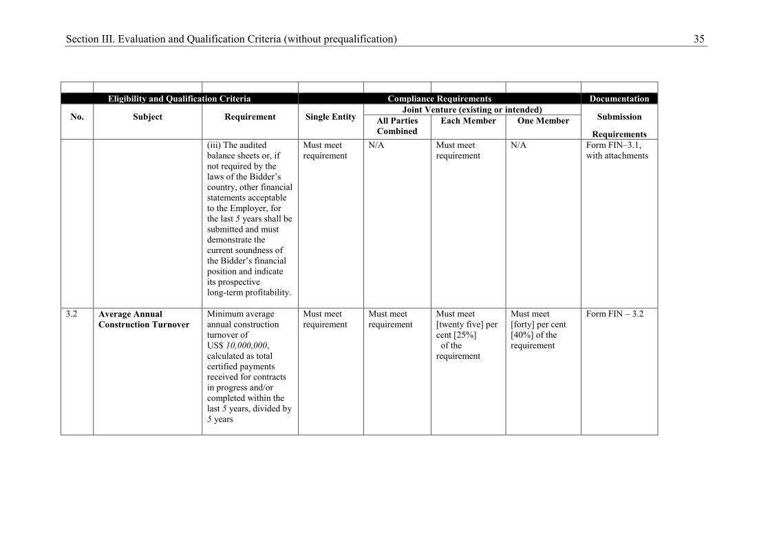
(iii) The audited balance sheets or, if not required by the laws of the Bidder’s country, other financial statements acceptable to the Employer, for the last 5 years shall be submitted and must demonstrate the current soundness of the Bidder’s financial position and indicate its prospective long-term profitability.
Must meet requirement
N/A Must meet requirement
N/A Form FIN–3.1, with attachments
3.2 Average Annual Construction Turnover
Minimum average annual construction turnover of US$ 10,000,000, calculated as total certified payments received for contracts in progress and/or completed within the last 5 years, divided by 5 years
Must meet requirement
Must meet requirement
Must meet [twenty five] per cent [25%] of the requirement
Must meet [forty] per cent [40%] of the requirement
Form FIN – 3.2
36 Section III. Evaluation and Qualification Criteria (without prequalification)
Eligibility and Qualification Criteria Compliance Requirements Documentation
No. Subject Requirement Single Entity Joint Venture (existing or intended)
Submission
Requirements All Parties Combined
Each Member One Member
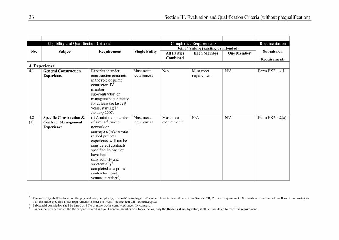
4. Experience 4.1 General Construction
Experience Experience under construction contracts in the role of prime contractor, JV member, sub-contractor, or management contractor for at least the last 10 years, starting 1st January 2007.
Must meet requirement
N/A Must meet requirement
N/A Form EXP – 4.1
4.2 (a)
Specific Construction & Contract Management Experience
(i) A minimum number of similar3 water network or conveyors,(Wastewater related projects experience will not be considered) contracts specified below that have been satisfactorily and substantially4 completed as a prime contractor, joint venture member5,
Must meet requirement
Must meet requirement9
N/A
N/A
Form EXP-4.2(a)
3 The similarity shall be based on the physical size, complexity, methods/technology and/or other characteristics described in Section VII, Work’s Requirements. Summation of number of small value contracts (less
than the value specified under requirement) to meet the overall requirement will not be accepted. 4 Substantial completion shall be based on 80% or more works completed under the contract. 5 For contracts under which the Bidder participated as a joint venture member or sub-contractor, only the Bidder’s share, by value, shall be considered to meet this requirement.
Section III. Evaluation and Qualification Criteria (without prequalification) 37
Eligibility and Qualification Criteria Compliance Requirements Documentation
No. Subject Requirement Single Entity Joint Venture (existing or intended)
Submission
Requirements All Parties Combined
Each Member One Member
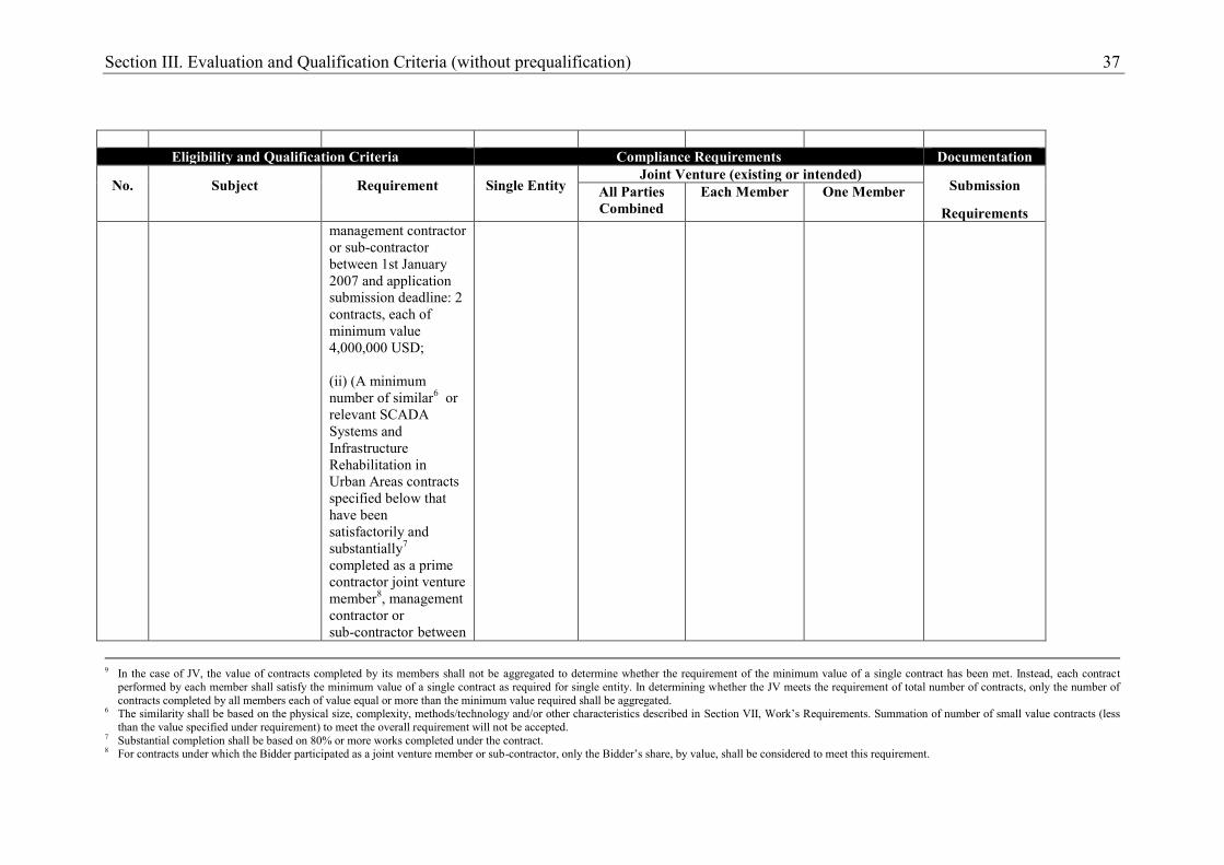
management contractor or sub-contractor between 1st January 2007 and application submission deadline: 2 contracts, each of minimum value 4,000,000 USD; (ii) (A minimum number of similar6 or relevant SCADA Systems and Infrastructure Rehabilitation in Urban Areas contracts specified below that have been satisfactorily and substantially7 completed as a prime contractor joint venture member8, management contractor or sub-contractor between
9 In the case of JV, the value of contracts completed by its members shall not be aggregated to determine whether the requirement of the minimum value of a single contract has been met. Instead, each contract
performed by each member shall satisfy the minimum value of a single contract as required for single entity. In determining whether the JV meets the requirement of total number of contracts, only the number of contracts completed by all members each of value equal or more than the minimum value required shall be aggregated.
6 The similarity shall be based on the physical size, complexity, methods/technology and/or other characteristics described in Section VII, Work’s Requirements. Summation of number of small value contracts (less than the value specified under requirement) to meet the overall requirement will not be accepted.
7 Substantial completion shall be based on 80% or more works completed under the contract. 8 For contracts under which the Bidder participated as a joint venture member or sub-contractor, only the Bidder’s share, by value, shall be considered to meet this requirement.
38 Section III. Evaluation and Qualification Criteria (without prequalification)
Eligibility and Qualification Criteria Compliance Requirements Documentation
No. Subject Requirement Single Entity Joint Venture (existing or intended)
Submission
Requirements All Parties Combined
Each Member One Member
1st January 2007 and application submission deadline: 1 contract
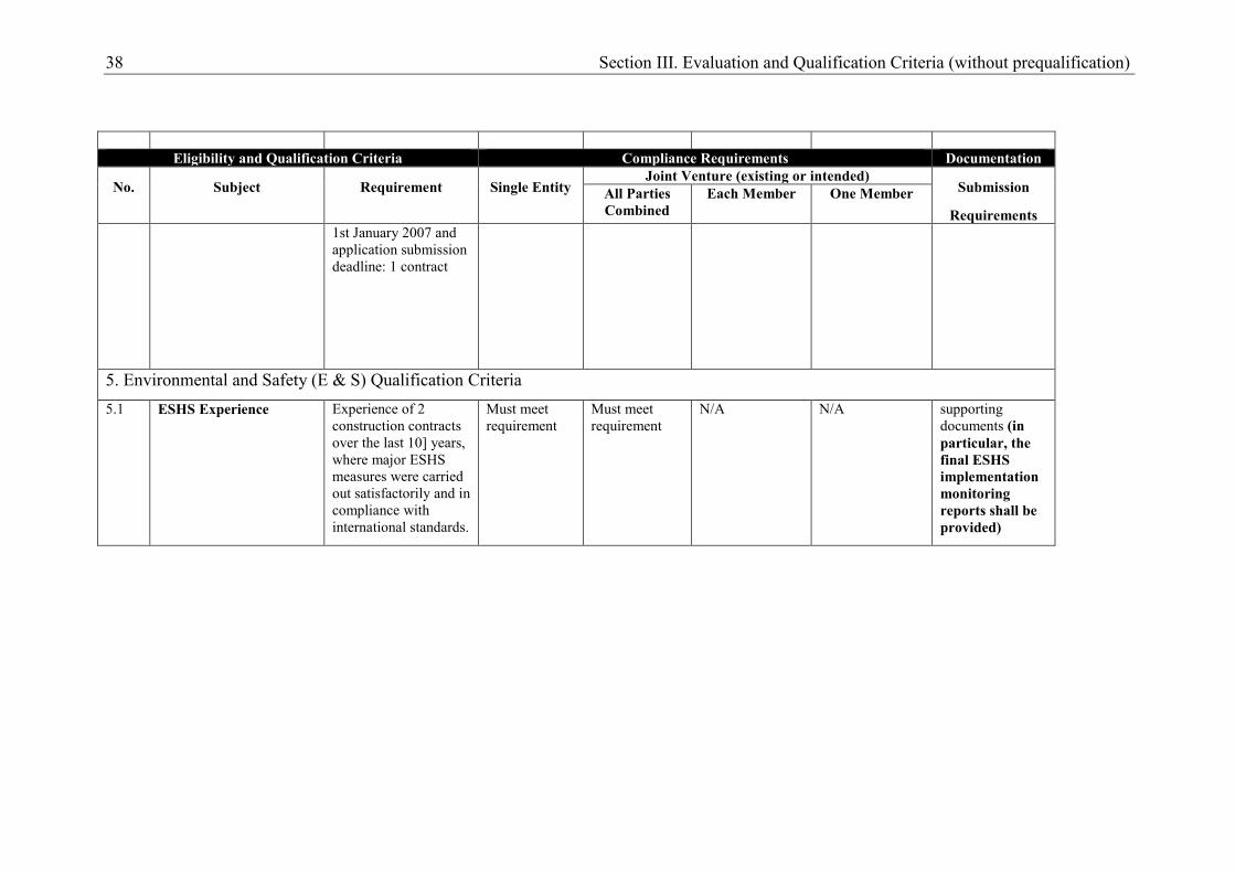
5. Environmental and Safety (E & S) Qualification Criteria
5.1 ESHS Experience Experience of 2 construction contracts over the last 10] years, where major ESHS measures were carried out satisfactorily and in compliance with international standards.
Must meet requirement
Must meet requirement
N/A N/A supporting documents (in particular, the final ESHS implementation monitoring reports shall be provided)
Section III. Evaluation and Qualification Criteria (without prequalification) 39
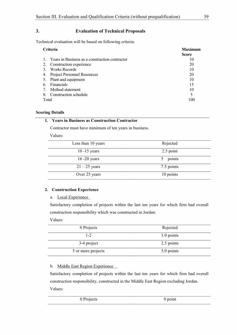
3. Evaluation of Technical Proposals Technical evaluation will be based on following criteria:
Criteria Maximum Score
1. Years in Business as a construction contractor 10 2. Construction experience 20 3. Works Records 10 4. Project Personnel Resources 20 5. Plant and equipment 10 6. Financials 15 7. Method statement 10 8. Construction schedule 5 Total 100
Scoring Details
1. Years in Business as Construction Contractor
Contractor must have minimum of ten years in business.
Values:
Less than 10 years Rejected
10 -15 years 2.5 point
16 -20 years 5 points
21 – 25 years 7.5 points
Over 25 years 10 points
2. Construction Experience
a. Local Experience
Satisfactory completion of projects within the last ten years for which firm had overall
construction responsibility which was constructed in Jordan:
Values:
0 Projects Rejected
1-2 1.0 points
3-4 project 2.5 points
5 or more projects 5.0 points
b. Middle East Region Experience
Satisfactory completion of projects within the last ten years for which firm had overall
construction responsibility, constructed in the Middle East Region excluding Jordan.
Values:
0 Projects 0 point

40 Section III. Evaluation and Qualification Criteria (without prequalification)
1 project 2.5 points
2 or more projects 5.0 points
c. Water Networks Projects Experience
Satisfactory completion of projects in the field of water networks within the last ten years
for which the firm had overall construction responsibility.
Values:
0 Projects Rejected
1 - 2 projects 1.0 points
3- 4 projects 3.0 points
4 or more projects 4.0 points
d. Similar Project Experience
Satisfactory completion of similar projects (Water Networks in Urban Area) within the
last ten years for which the firm had overall construction responsibility. The project must
have included the construction of water conveyers line (>800 mm Diameter Pipelines)
Values:
0 Projects 0 Point
1 project 1.0 points
2 projects 3.0 points
3 or more projects 6.0 points
3. Works Records
a. Projects Penalties
The contractor must submit full details of projects penalties (if any) for the last ten years.
Values:
Penalties on more than One Project 0.0 point
Penalties on One Project 3.0 points
No Penalties 6.0 points
b. Contracts in Progress
Bidders shall list references from the Clients for which contracts are listed on the
experience details. Particularly include references for those project types most closely
representing the one for which the current application is made. The listing should
include the name, address, telephone and fax numbers, and email address of the
appropriate Client Representative or current contact person.

Section III. Evaluation and Qualification Criteria (without prequalification) 41
Number of projects currently in progress or recently awarded whether as the prime
contractor or subcontractor.
Values:
0 Projects 0 point
1 project 1.0 points
2 projects 2.0 points
3 projects or more 4.0 points
c. Client References
4. Personnel resources
a. Project Manager Experience
Values:
<12 years total work experience Rejected
12-15 years total work experience 0.0 points
15-20 years total work experience 2.5 points
>20 years total work experience 5.0 points
Values:
<10 years work experience in Water &
Wastewater Projects Rejected
10-15 years work experience in Water &
Wastewater Projects 2.5 points
>15 years work experience in Water &
Wastewater Projects 5.0 points
b. Site Engineer Experience
Values:
<8 years total work experience Rejected
8-10 years total work experience 0.0 points
10-15 years total work experience 2 points
>15 years total work experience 3 points
Values:
<5 years work experience in Water &
Wastewater Projects Rejected
42 Section III. Evaluation and Qualification Criteria (without prequalification)
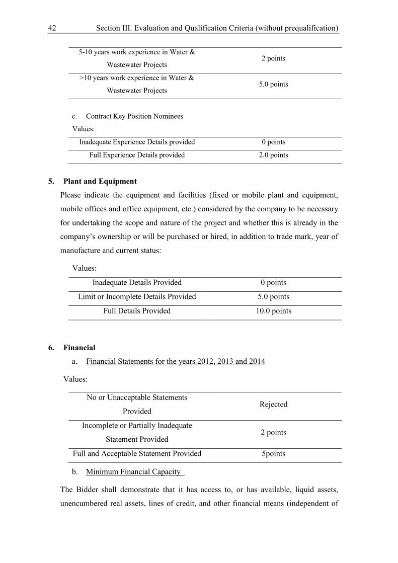
5-10 years work experience in Water &
Wastewater Projects 2 points
>10 years work experience in Water &
Wastewater Projects 5.0 points
c. Contract Key Position Nominees
Values:
Inadequate Experience Details provided 0 points
Full Experience Details provided 2.0 points
5. Plant and Equipment
Please indicate the equipment and facilities (fixed or mobile plant and equipment,
mobile offices and office equipment, etc.) considered by the company to be necessary
for undertaking the scope and nature of the project and whether this is already in the
company’s ownership or will be purchased or hired, in addition to trade mark, year of
manufacture and current status:
Values:
Inadequate Details Provided 0 points
Limit or Incomplete Details Provided 5.0 points
Full Details Provided 10.0 points
6. Financial
a. Financial Statements for the years 2012, 2013 and 2014
Values:
No or Unacceptable Statements
Provided Rejected
Incomplete or Partially Inadequate
Statement Provided 2 points
Full and Acceptable Statement Provided 5points
b. Minimum Financial Capacity
The Bidder shall demonstrate that it has access to, or has available, liquid assets,
unencumbered real assets, lines of credit, and other financial means (independent of
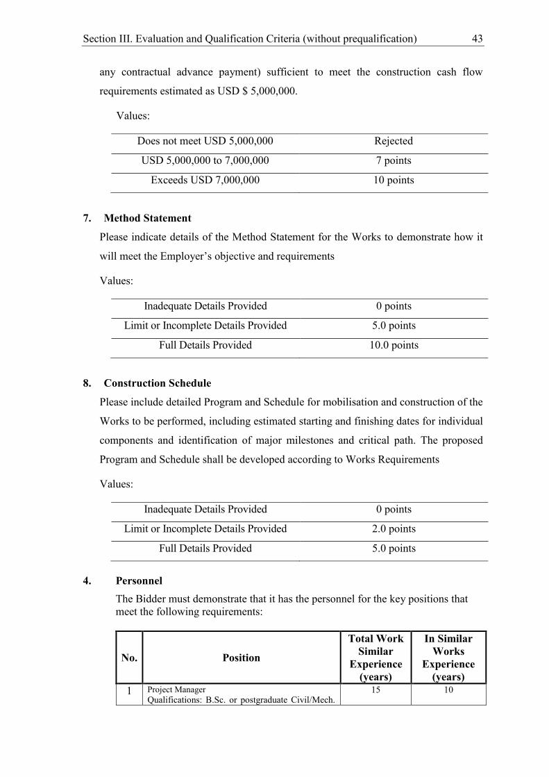
Section III. Evaluation and Qualification Criteria (without prequalification) 43
any contractual advance payment) sufficient to meet the construction cash flow
requirements estimated as USD $ 5,000,000.
Values:
Does not meet USD 5,000,000 Rejected
USD 5,000,000 to 7,000,000 7 points
Exceeds USD 7,000,000 10 points
7. Method Statement
Please indicate details of the Method Statement for the Works to demonstrate how it
will meet the Employer’s objective and requirements
Values:
Inadequate Details Provided 0 points
Limit or Incomplete Details Provided 5.0 points
Full Details Provided 10.0 points
8. Construction Schedule
Please include detailed Program and Schedule for mobilisation and construction of the
Works to be performed, including estimated starting and finishing dates for individual
components and identification of major milestones and critical path. The proposed
Program and Schedule shall be developed according to Works Requirements
Values:
Inadequate Details Provided 0 points
Limit or Incomplete Details Provided 2.0 points
Full Details Provided 5.0 points
4. Personnel
The Bidder must demonstrate that it has the personnel for the key positions that meet the following requirements:
No. Position
Total Work Similar
Experience (years)
In Similar Works
Experience (years)
1 Project Manager Qualifications: B.Sc. or postgraduate Civil/Mech.
15 10

44 Section III. Evaluation and Qualification Criteria (without prequalification)
Engineering, with a minimum experience of 15 years, in which 10 years of experience are in the construction of water projects, experience should include successfully completing a previous position as project manager/construction manager on at least 2 large water projects that is based on FIDIC conditions of contract.
2 Site Engineer (Civil) Qualifications: B.Sc. Civil engineering, with a minimum experience of 10 years, in which 5 years of experience are in a previous position as a site engineer on a project of similar nature (water projects).
10 5
3 Site Engineer (Mechanical) Qualifications: B.Sc. mechanical engineering, with a minimum experience of 10 years, in which 5 years of experience are in a previous position as a site engineer on a project of similar nature (water projects).
10 5
3 Site Inspector Qualifications: Diploma or B.Sc. Civil/ Mechanical engineering, with a minimum of 10 years of experience, in which 5 years of experience are in the construction of water projects with particular experience in connecting and disconnecting new water pipelines with existing ones.
10 5
4 Surveyor 10 5 5 Lab Technician 10 5 6 Health and Safety Engineer 6 4
Note: The contractor’s staffing should take into consideration Bylaw (131) for 2016 The Compulsory Employment of Jordanian Labor from Governorate’s Residents in Construction Projects
The Bidder shall provide details of the proposed personnel and their experience records using Forms PER-1 and PER-2 included in Section IV, Bidding Forms.
5. Equipment
The Bidder must demonstrate that it has the key equipment listed hereafter:
No. Equipment Type and Characteristics Minimum Number required
1 Excavator/ Jack Hammer 3 2 Loader 3 3 Dump Truck 6 4 Asphalt Cutter 1 5 Air Compressor 2 6 Water Tank 1 7 Asphalt tanker (MC Sprayer) 1 8 Air Compressor 1 9 Backfilling Roller 3 10 Pickup Truck 2

Section III. Evaluation and Qualification Criteria (without prequalification) 45
The Bidder shall provide further details of proposed items of equipment using Form EQU in Section IV, Bidding Forms.
6. Domestic Preference Not Applicable
46 Section IV. Bidding Forms
Section IV. Bidding Forms
Table of Forms Letter of Bid............................................................................................................................47
Appendix to Bid......................................................................................................................49 Summary of Payment Currencies ................................................................................49 Statement of Integrity, Eligibility and Social and Environmental Responsibility .......50
Schedules .................................................................................................................................53
Technical Proposal .................................................................................................................54 Site Organization .........................................................................................................55 Method Statement ........................................................................................................56 Construction Schedule .................................................................................................57 Form EQU: Equipment ................................................................................................58 Form PER-1: Proposed Personnel ...............................................................................59 Form PER-2: Resume of Proposed Personnel .............................................................60
Bidders Qualification without prequalification ..................................................................61 Form ELI -1.1 ..............................................................................................................62 Form ELI -1.2 ..............................................................................................................63 Form CON – 2 .............................................................................................................64 Form FIN – 3.1: ...........................................................................................................66 Form FIN – 3.2: ...........................................................................................................68 Form FIN – 3.3: ...........................................................................................................69 Form FIN – 3.4: ...........................................................................................................70 Form EXP - 4 .1 ..........................................................................................................71 Form EXP - 4.2(a) ....................................................................................................72
Form of Bid Security .............................................................................................................74
Form of Bid-Securing Declaration .......................................................................................76
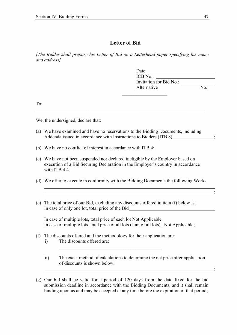
Section IV. Bidding Forms 47
Letter of Bid
[The Bidder shall prepare his Letter of Bid on a Letterhead paper specifying his name and address]
Date: ICB No.: Invitation for Bid No.: Alternative No.:
___________________ To: _______________________________________________________________________ We, the undersigned, declare that: (a) We have examined and have no reservations to the Bidding Documents, including
Addenda issued in accordance with Instructions to Bidders (ITB 8) ; (b) We have no conflict of interest in accordance with ITB 4; (c) We have not been suspended nor declared ineligible by the Employer based on
execution of a Bid Securing Declaration in the Employer’s country in accordance with ITB 4.4.
(d) We offer to execute in conformity with the Bidding Documents the following Works:
;
(e) The total price of our Bid, excluding any discounts offered in item (f) below is:
In case of only one lot, total price of the Bid In case of multiple lots, total price of each lot Not Applicable In case of multiple lots, total price of all lots (sum of all lots)_ Not Applicable;
(f) The discounts offered and the methodology for their application are:
i) The discounts offered are: ___________________________________________
ii) The exact method of calculations to determine the net price after application
of discounts is shown below: ;
(g) Our bid shall be valid for a period of 120 days from the date fixed for the bid
submission deadline in accordance with the Bidding Documents, and it shall remain binding upon us and may be accepted at any time before the expiration of that period;
48 Section IV. Bidding Forms
(h) If our bid is accepted, we commit to obtain a performance security in accordance with ITB 42 of the Bidding Documents;
(i) We are not participating, as a Bidder, in more than one bid in this bidding process in
accordance with ITB 4.2(e), other than alternative bids submitted in accordance with ITB 13;
(j) We have paid, or will pay the following commissions, gratuities, or fees with respect
to the bidding process or execution of the Contract:
Name of Recipient Address Reason Amount
[If none has been paid or is to be paid, indicate “none.”]
(k) We understand that this bid, together with your written acceptance thereof included
in your notification of award, shall constitute a binding contract between us, until a formal contract is prepared and executed; and
(l) We understand that you are not bound to accept the lowest evaluated bid or any other
bid that you may receive. (m) We hereby certify that we have taken steps to ensure that no person acting for us or
on our behalf will engage in any type of fraud and corruption. Name of the Bidder* Name of the person duly authorized to sign the Bid on behalf of the Bidder** Title of the person signing the Bid Signature of the person named above Date signed ________________________________ day of __________________, _____ *: In the case of the Bid submitted by joint venture specify the name of the Joint Venture as Bidder **: Person signing the Bid shall have the power of attorney given by the Bidder to be attached with the Bid

Section IV. Bidding Forms 49
Appendix to Bid
Summary of Payment Currencies
Bidders to quote entirely in local currency (Jordanian Dinars) and as per (clause BDS 15.1)

50 Section IV. Bidding Forms
Statement of Integrity, Eligibility and Social and Environmental
Responsibility Reference name of the Bid : ("Contract") To: ("Contracting Authority")
1. We recognise and accept that Agence française de développement ("AFD") only finances projects of the Contracting Authority subject to its own conditions which are set out in the Financing Agreement which it has entered into with the Contracting Authority. As a matter of consequence, no legal relationship exists between AFD and our company, our joint venture or our subcontractors. The Contracting Authority retains exclusive responsibility for the preparation and implementation of the contract procurement and its subsequent performance.
2. We hereby certify that neither we nor any other member of our joint venture or any of our subcontractors are in any of the following situations:
2.1) being bankrupt, wound up or ceasing our activities, having our activities administered by the courts, having entered into receivership, reorganisation or being in any analogous situation arising from any similar procedure;
2.2) having been convicted, within the past five years by decision of a court decision, which has the force of res judicata in the country where the project is implemented, of one of the acts mentioned in sections 6.1 to 6.4 below or of any other offense committed during the procurement or performance of a contract1;
2.3) being listed for financial sanctions by the United Nations, the European Union and/or France for the purposes of fight-against-terrorist financing or threat to international peace and security;
2.4) having committed serious professional misconduct within the past five years during the procurement or performance of a contract;
2.5) not having fulfilled our obligations regarding the payment of social security contributions or taxes in accordance with the legal provisions of either the country where we are established or the Contracting Authority's country;
2.6) having been convicted, within the past five years by a court decision, which has the force of res judicata, of one of the acts mentioned in sections 6.1 to 6.4 below or of any other offense committed during the procurement or performance of an AFD-financed contract;
2.7) being subject to an exclusion decision of the World Bank since 30 May 2012, and being listed on the website http://www.worldbank.org/debarr3;
1 In the event of such conviction, you may attach to this Statement of Integrity supporting information
showing that this conviction is not relevant in the context of this AFD-financed contract. 2 In the event of such exclusion, you may attach to this Statement of Integrity supporting information
showing that this exclusion is not relevant in the context of this AFD-financed contract. 3 In the event of such exclusion, you may attach to this Statement of Integrity supporting information
showing that this exclusion is not relevant in the context of this AFD-financed contract.
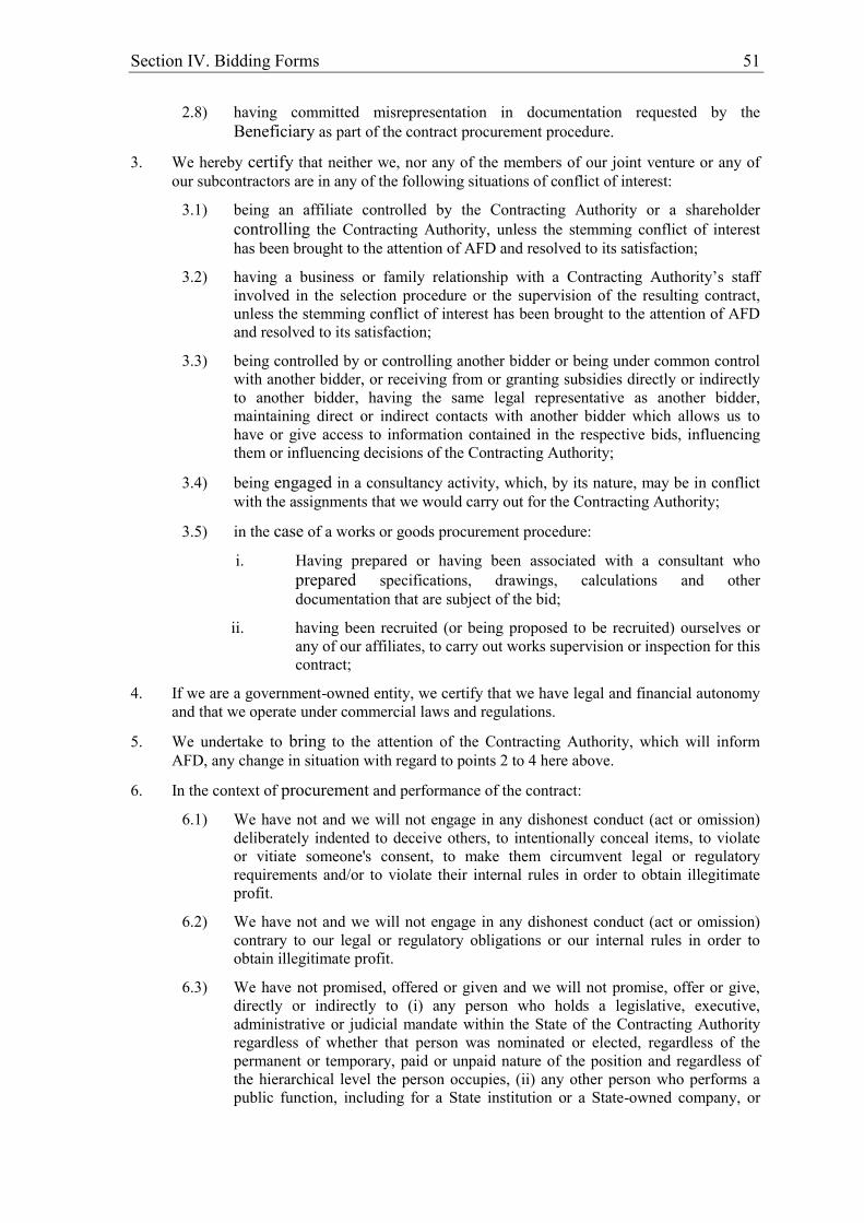
Section IV. Bidding Forms 51
2.8) having committed misrepresentation in documentation requested by the Beneficiary as part of the contract procurement procedure.
3. We hereby certify that neither we, nor any of the members of our joint venture or any of our subcontractors are in any of the following situations of conflict of interest:
3.1) being an affiliate controlled by the Contracting Authority or a shareholder controlling the Contracting Authority, unless the stemming conflict of interest has been brought to the attention of AFD and resolved to its satisfaction;
3.2) having a business or family relationship with a Contracting Authority’s staff involved in the selection procedure or the supervision of the resulting contract, unless the stemming conflict of interest has been brought to the attention of AFD and resolved to its satisfaction;
3.3) being controlled by or controlling another bidder or being under common control with another bidder, or receiving from or granting subsidies directly or indirectly to another bidder, having the same legal representative as another bidder, maintaining direct or indirect contacts with another bidder which allows us to have or give access to information contained in the respective bids, influencing them or influencing decisions of the Contracting Authority;
3.4) being engaged in a consultancy activity, which, by its nature, may be in conflict with the assignments that we would carry out for the Contracting Authority;
3.5) in the case of a works or goods procurement procedure:
i. Having prepared or having been associated with a consultant who prepared specifications, drawings, calculations and other documentation that are subject of the bid;
ii. having been recruited (or being proposed to be recruited) ourselves or any of our affiliates, to carry out works supervision or inspection for this contract;
4. If we are a government-owned entity, we certify that we have legal and financial autonomy and that we operate under commercial laws and regulations.
5. We undertake to bring to the attention of the Contracting Authority, which will inform AFD, any change in situation with regard to points 2 to 4 here above.
6. In the context of procurement and performance of the contract:
6.1) We have not and we will not engage in any dishonest conduct (act or omission) deliberately indented to deceive others, to intentionally conceal items, to violate or vitiate someone's consent, to make them circumvent legal or regulatory requirements and/or to violate their internal rules in order to obtain illegitimate profit.
6.2) We have not and we will not engage in any dishonest conduct (act or omission) contrary to our legal or regulatory obligations or our internal rules in order to obtain illegitimate profit.
6.3) We have not promised, offered or given and we will not promise, offer or give, directly or indirectly to (i) any person who holds a legislative, executive, administrative or judicial mandate within the State of the Contracting Authority regardless of whether that person was nominated or elected, regardless of the permanent or temporary, paid or unpaid nature of the position and regardless of the hierarchical level the person occupies, (ii) any other person who performs a public function, including for a State institution or a State-owned company, or
52 Section IV. Bidding Forms
who provides a public service, or (iii) any other person defined as a public officer by the national laws of the Contracting Authority, an undue advantage of any kind, for himself or for another person or entity, for such public officer to act or refrain from acting in his official capacity.
6.4) We have not promised, offered or given and we will not promise, offer or give, directly or indirectly to any private person who occupies an executive position in a private sector entity or works for such an entity, regardless of the nature of his/her capacity, any undue advantage of any kind, for himself or another person or entity for such private person to perform or refrain from performing any act in breach of its legal, contractual or professional obligations.
6.5) We have not and we will not engage in any practice likely to influence the contract award process to the detriment of the Contracting Authority and, in particular, in any anti-competitive practice having for object or for effect to prevent, restrict or distort competition, namely by limiting access to the market or the free exercise of competition by other undertakings.
6.6) Neither we nor any of the members of our joint venture or any of our subcontractors shall acquire or supply any equipment nor operate in any sectors under an embargo of the United Nations, the European Union or France.
6.7) We commit ourselves to comply with and ensure that all of our subcontractors comply with international environmental and labour standards, consistent with laws and regulations applicable in the country of implementation of the contract, including the fundamental conventions of the International Labour Organisation (ILO) and international environmental treaties,. Moreover, we shall implement environmental and social risks mitigation measures such as specified in the environmental and social management plan or, if appropriate, in the environmental and social impact assessment notice provided by the Contracting Authority.
7. We, as well as members of our joint venture and our subcontractors authorise AFD to inspect accounts, records and other documents relating to the procurement and performance of the Contract and to have them audited by auditors appointed by AFD.
Name:____________________ In the capacity of _____________________
Signature:______________________________
Duly empowered to sign the bid in the name and on behalf of4____________________
4 In case of joint venture, insert the name of the joint venture. The person who will sign the bid on behalf
of the bidder shall attach a power of attorney from the bidder.

Section IV. Bidding Forms 53
Schedules
Rates and prices shall take into account the applicable tax exemptions specified in clause 14.1 (b) of the Particular Conditions of Contract.
54 Section IV. Bidding Forms
Technical Proposal
- Site Organization - Method Statement
- Construction Schedule - Equipment - Form EQU
- Personnel – Forms PER-1 and PER-2

Section IV. Bidding Forms 55
Site Organization
56 Section IV. Bidding Forms
Method Statement Each Bidder shall set out details of the Method Statement for the Works to demonstrate how it will meet the Employer’s objective and requirements. As a minimum, the Method Statement shall address the following: (a) Details of the arrangements and methods which the Bidder proposes to implement
for the construction of the Works, in sufficient detail to demonstrate their adequacy to achieve the requirements of the Contract including completion within the Time for Completion stated in the Particular Conditions of Contract.
(b) Details on the management methodology, approach and risk mitigation and/or avoidance measures that the bidder proposes for the construction of the works in urban, crowded, narrow and congested areas
(c) Outline of the arrangements of the Bidder to manage coordination of Site access. (d) Comments on the geotechnical and subsurface aspects of the Works including
materials, material sources and any constraints. (e) Comments on logistics and traffic management (f) Outline of the arrangements and organisation of the Bidder to ensure compliance
with the Works Requirements. (g) Outline of the arrangements of the Bidder to carry out testing upon completion as
specified in the Works Requirements.
Section IV. Bidding Forms 57
Construction Schedule
Each Bidder shall set out a detailed Program and Schedule for mobilisation and construction of the Works to be performed, including estimated starting and finishing dates for individual components and identification of major milestones and critical path. The proposed Program and Schedule shall be developed according to Works Requirements and shall address the following:
(a) Details of the proposed schedule for obtaining permits that may be necessary in
order to commence the Works, including the preparation of required studies, supporting information, and applications.
(b) Details of the proposed timeline for carrying out the Works within the Time for
Completion, in the form of a bar chart showing notably the critical path.
(c) Details of the proposed timeline for the testing, commissioning and handing over of the completed Works.

58 Section IV. Bidding Forms
Form EQU: Equipment The Bidder shall provide adequate information to demonstrate clearly that it has the capability to meet the requirements for the key equipment listed in Section III, Evaluation and Qualification Criteria. A separate Form shall be prepared for each item of equipment listed, or for alternative equipment proposed by the Bidder. Item of equipment Equipment information
Name of manufacturer
Model and power rating
Capacity
Year of manufacture
Current status Current location
Details of current commitments
Source Indicate source of the equipment
Owned Rented Leased Specially manufactured Omit the following information for equipment owned by the Bidder. Owner Name of owner Address of owner
Telephone Contact name and title Fax Telex Agreements Details of rental / lease / manufacture agreements specific to the project

Section IV. Bidding Forms 59
Personnel
Form PER-1: Proposed Personnel
Bidders should provide the names of suitably qualified personnel to meet the specified requirements stated in Section III. The data on their experience should be supplied using the Form below for each candidate.
1. Title of position*
Name
2. Title of position*
Name
3. Title of position*
Name
4. Title of position*
Name
*As listed in Section III.
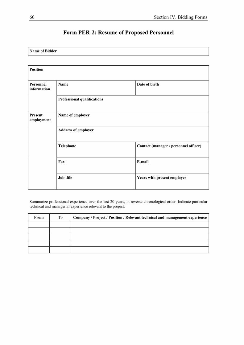
60 Section IV. Bidding Forms
Form PER-2: Resume of Proposed Personnel
Name of Bidder
Position
Personnel information
Name
Date of birth
Professional qualifications
Present employment
Name of employer
Address of employer
Telephone
Contact (manager / personnel officer)
Fax
Job title
Years with present employer
Summarize professional experience over the last 20 years, in reverse chronological order. Indicate particular technical and managerial experience relevant to the project.
From To Company / Project / Position / Relevant technical and management experience
Section IV. Bidding Forms 61
Bidders Qualification without prequalification
To establish its qualifications to perform the contract in accordance with Section III (Evaluation and Qualification Criteria) the Bidder shall provide the information requested in the corresponding Information Sheets included hereunder.
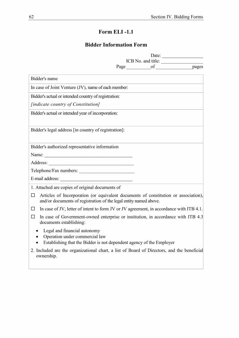
62 Section IV. Bidding Forms
Form ELI -1.1
Bidder Information Form
Date: _________________ ICB No. and title: _________________
Page __________of _______________pages
Bidder's name
In case of Joint Venture (JV), name of each member:
Bidder's actual or intended country of registration: [indicate country of Constitution]
Bidder's actual or intended year of incorporation:
Bidder's legal address [in country of registration]:
Bidder's authorized representative information Name: _____________________________________ Address: ___________________________________ Telephone/Fax numbers: _______________________ E-mail address: ______________________________
1. Attached are copies of original documents of Articles of Incorporation (or equivalent documents of constitution or association),
and/or documents of registration of the legal entity named above. In case of JV, letter of intent to form JV or JV agreement, in accordance with ITB 4.1. In case of Government-owned enterprise or institution, in accordance with ITB 4.3
documents establishing:
Legal and financial autonomy Operation under commercial law Establishing that the Bidder is not dependent agency of the Employer
2. Included are the organizational chart, a list of Board of Directors, and the beneficial ownership.
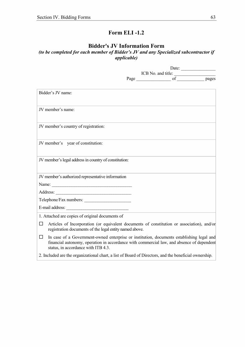
Section IV. Bidding Forms 63
Form ELI -1.2
Bidder's JV Information Form (to be completed for each member of Bidder’s JV and any Specialized subcontractor if
applicable)
Date: _______________ ICB No. and title: __________________
Page _______________ of ____________ pages
Bidder’s JV name:
JV member’s name:
JV member’s country of registration:
JV member’s year of constitution:
JV member’s legal address in country of constitution:
JV member’s authorized representative information Name: ____________________________________ Address: __________________________________ Telephone/Fax numbers: _____________________ E-mail address: _____________________________
1. Attached are copies of original documents of Articles of Incorporation (or equivalent documents of constitution or association), and/or
registration documents of the legal entity named above. In case of a Government-owned enterprise or institution, documents establishing legal and
financial autonomy, operation in accordance with commercial law, and absence of dependent status, in accordance with ITB 4.3.
2. Included are the organizational chart, a list of Board of Directors, and the beneficial ownership.

64 Section IV. Bidding Forms
Form CON – 2
Historical Contract Non-Performance, Pending Litigation and Litigation History
(to be completed by the Bidder and by each member of the Bidder’s JV)
Bidder’s Name: ________________ Date: ______________________
JV Member’s Name_________________________ ICB No. and title: ___________________________
Page _______________of ______________pages
Non-Performed Contracts in accordance with Section III, Evaluation and Qualification Criteria
Contract non-performance did not occur since 1st January [insert current year number less 5] specified in Section III, Evaluation and Qualification Criteria, Sub-Factor 2.1.
Contract(s) not performed since 1st January [insert current year number less 5] specified in Section III, Evaluation and Qualification Criteria, requirement 2.1
Year Non- performed portion of contract
Contract Identification
Total Contract Amount
(current value, currency,
exchange rate and
US$ equivalent)
[insert year]
[insert amount and percentage]
Contract Identification: [indicate complete contract name/ number, and any other identification] Name of Employer: [insert full name] Address of Employer: [insert street/city/country] Reason(s) for non-performance: [indicate main reason(s)]
[insert amount]
Pending Litigation, in accordance with Section III, Qualification Criteria and Requirements
No pending litigation in accordance with Section III, Qualification Criteria and Requirements, Sub-Factor 2.3.
Pending litigation in accordance with Section III, Evaluation and Qualification Criteria, Sub-Factor 2.3 as indicated below.
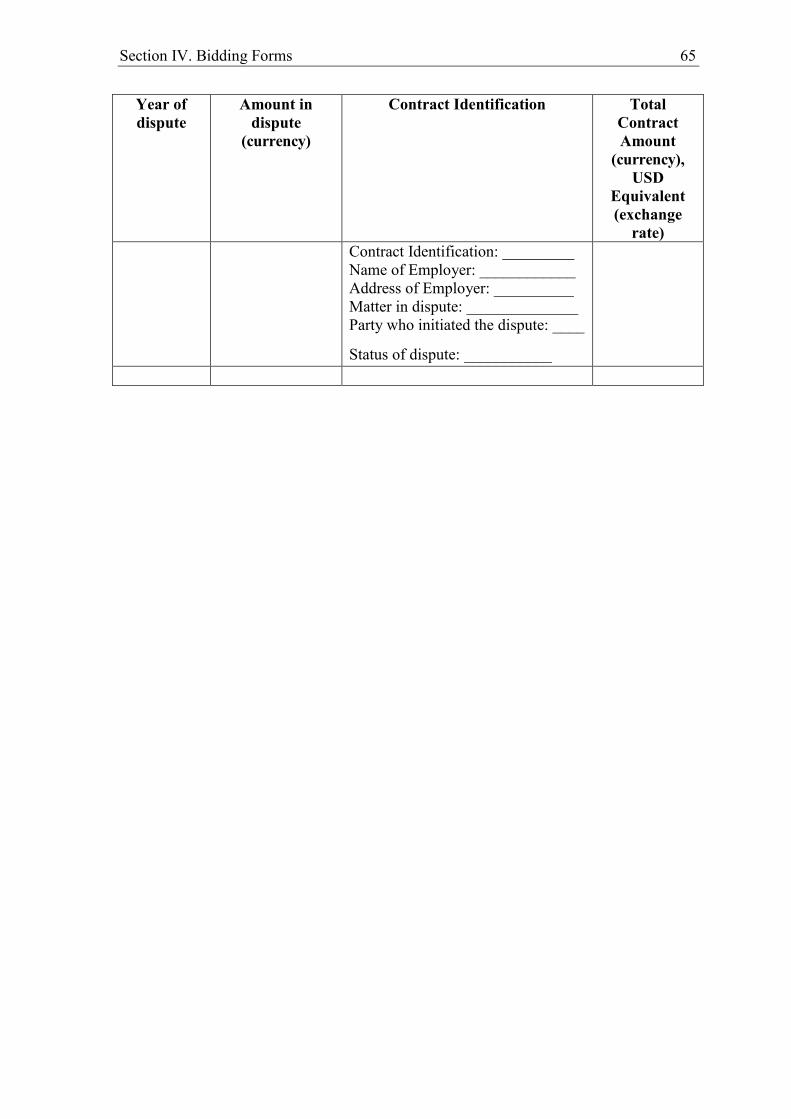
Section IV. Bidding Forms 65
Year of dispute
Amount in dispute
(currency)
Contract Identification Total Contract Amount
(currency), USD
Equivalent (exchange
rate) Contract Identification: _________
Name of Employer: ____________ Address of Employer: __________ Matter in dispute: ______________ Party who initiated the dispute: ____
Status of dispute: ___________

66 Section IV. Bidding Forms
Form FIN – 3.1:
Financial Situation and Performance
Bidder’s Name: ________________ Date: ______________________
JV Member’s Name_________________________ ICB No. and title: ___________________________
Page _______________of ______________pages
1. Financial data
Type of Financial
information in (currency)
Historic information for previous _________years, ______________
(amount in currency, currency, exchange rate*, USD equivalent)
Year 1 Year 2 Year 3 Year4 Year 5
Statement of Financial Position (Information from Balance Sheet)
Total Assets (TA)
Total Liabilities (TL)
Total Equity/Net Worth (NW)
Current Assets (CA)
Current Liabilities (CL)
Working Capital (WC)
Information from Income Statement
Total Revenue (TR)
Profits Before Taxes (PBT)
Cash Flow Information
Cash Flow from Operating Activities
*Refer to ITB 15 for the exchange rate 2. Financial documents
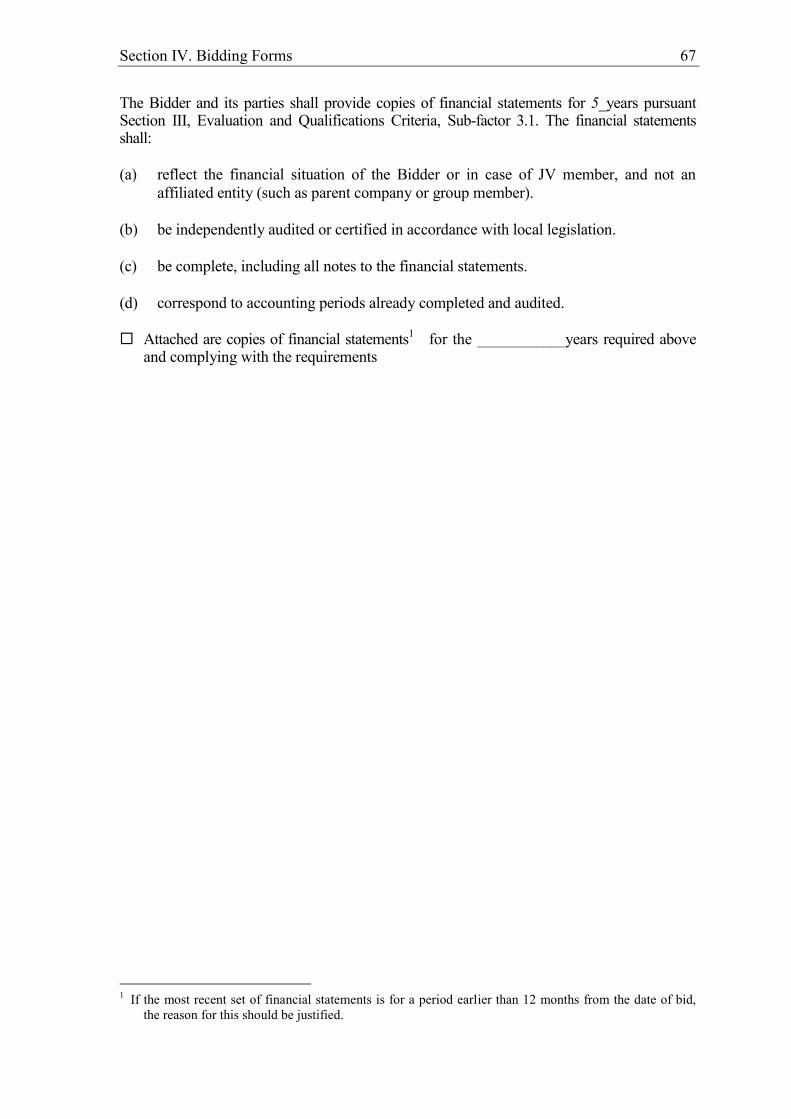
Section IV. Bidding Forms 67
The Bidder and its parties shall provide copies of financial statements for 5_years pursuant Section III, Evaluation and Qualifications Criteria, Sub-factor 3.1. The financial statements shall: (a) reflect the financial situation of the Bidder or in case of JV member, and not an
affiliated entity (such as parent company or group member). (b) be independently audited or certified in accordance with local legislation. (c) be complete, including all notes to the financial statements. (d) correspond to accounting periods already completed and audited. Attached are copies of financial statements1 for the ____________years required above
and complying with the requirements
1 If the most recent set of financial statements is for a period earlier than 12 months from the date of bid,
the reason for this should be justified.
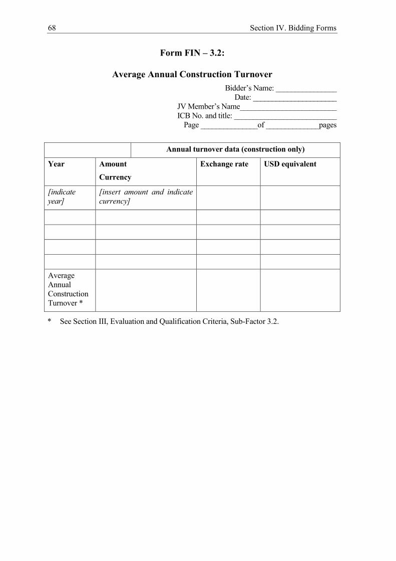
68 Section IV. Bidding Forms
Form FIN – 3.2:
Average Annual Construction Turnover Bidder’s Name: ________________
Date: ______________________ JV Member’s Name_________________________ ICB No. and title: ___________________________
Page _______________of ______________pages
Annual turnover data (construction only)
Year Amount Currency
Exchange rate USD equivalent
[indicate year]
[insert amount and indicate currency]
Average Annual Construction Turnover *
* See Section III, Evaluation and Qualification Criteria, Sub-Factor 3.2.
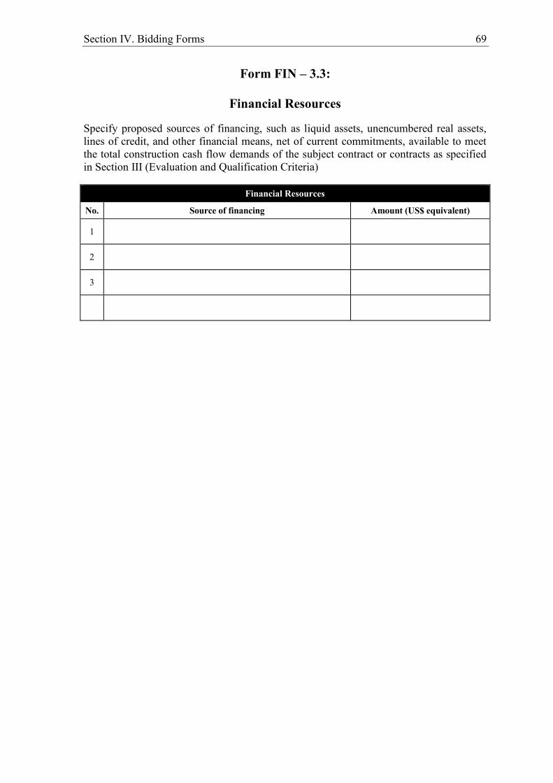
Section IV. Bidding Forms 69
Form FIN – 3.3:
Financial Resources
Specify proposed sources of financing, such as liquid assets, unencumbered real assets, lines of credit, and other financial means, net of current commitments, available to meet the total construction cash flow demands of the subject contract or contracts as specified in Section III (Evaluation and Qualification Criteria)
Financial Resources
No. Source of financing Amount (US$ equivalent)
1
2
3

70 Section IV. Bidding Forms
Form FIN – 3.4:
Current Contract Commitments / Works in Progress
Bidders and each member to a JV should provide information on their current commitments on all contracts that have been awarded, or for which a letter of intent or acceptance has been received, or for contracts approaching completion, but for which an unqualified, full completion certificate has yet to be issued.
Current Contract Commitments
No. Name of Contract Employer’s
Contact Address, Tel, Fax
Value of Outstanding
Work [Current
US$ Equivalent]
Estimated Completion
Date
Average Monthly Invoicing Over
Last Six Months [US$/month)]
1
2
3
4
5
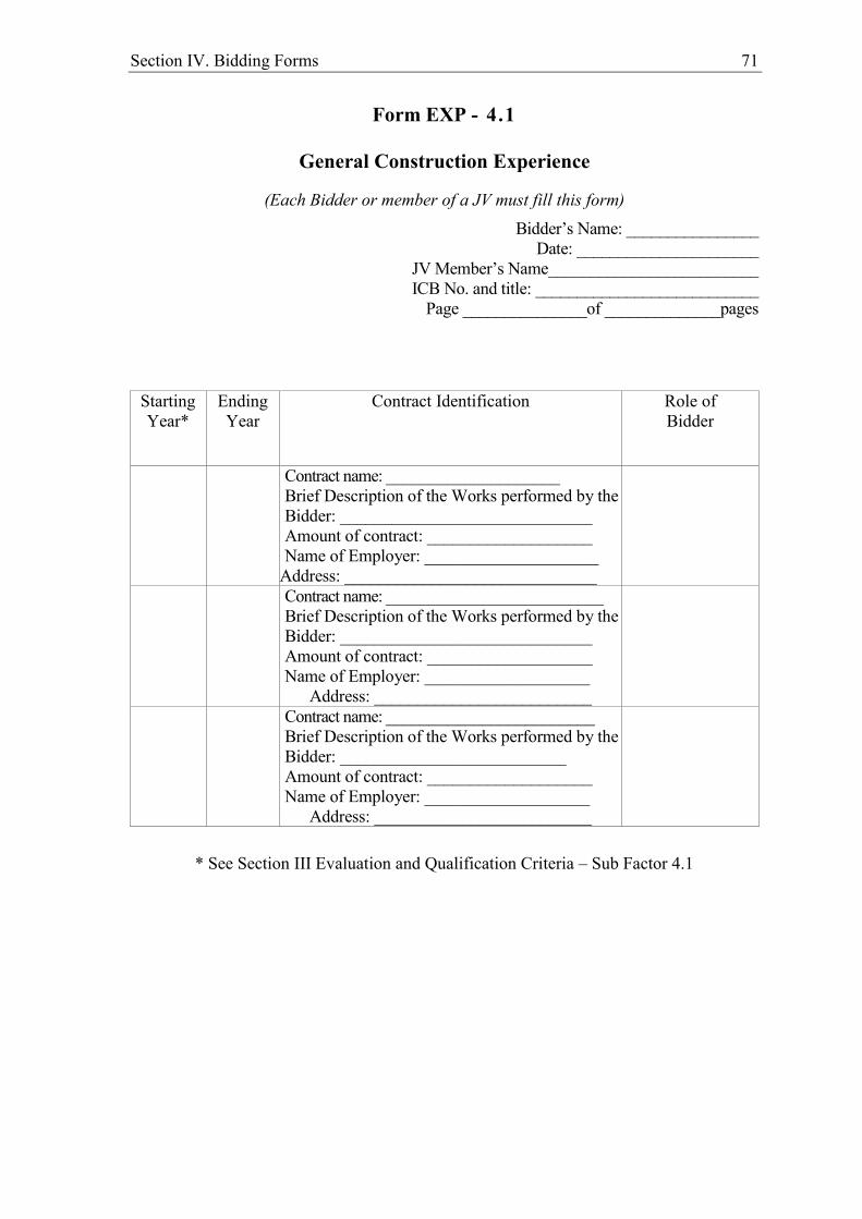
Section IV. Bidding Forms 71
Form EXP - 4.1
General Construction Experience
(Each Bidder or member of a JV must fill this form) Bidder’s Name: ________________
Date: ______________________ JV Member’s Name_________________________ ICB No. and title: ___________________________
Page _______________of ______________pages
Starting Year*
Ending Year
Contract Identification Role of Bidder
Contract name: ____________________ Brief Description of the Works performed by the Bidder: _____________________________ Amount of contract: ___________________ Name of Employer: ____________________
Address: _____________________________
Contract name: _________________________ Brief Description of the Works performed by the Bidder: _____________________________ Amount of contract: ___________________ Name of Employer: ___________________
Address: _________________________
Contract name: ________________________ Brief Description of the Works performed by the Bidder: __________________________ Amount of contract: ___________________ Name of Employer: ___________________
Address: _________________________
* See Section III Evaluation and Qualification Criteria – Sub Factor 4.1

72 Section IV. Bidding Forms
Form EXP - 4.2(a)
Specific Construction and Contract Management Experience
(each Bidder or member of a JV must fill this form)
Bidder’s Name: ________________ Date: ______________________
JV Member’s Name_________________________ ICB No. and title: ___________________________
Page _______________of ______________pages
Similar Contract No.
Information
Contract Identification
Award date
Completion date
Role in Contract
Prime Contractor
Member in JV
Management Contractor
Sub-contractor
Total Contract Amount US$ equivalent
If member in a JV or sub-contractor, specify participation in total Contract amount
Employer's Name: Address:
Telephone/fax number
E-mail:

Section IV. Bidding Forms 73
Form EXP - 4.2(a) (cont.) Specific Construction and Contract Management Experience (cont.)
Similar Contract No.
Information
Description of the similarity in accordance with Sub-Factor 4.2(a) of Section III:
1. Amount
2. Physical size of required works items
3. Complexity
4. Methods/Technology
5. Construction rate for key activities
6. Other Characteristics
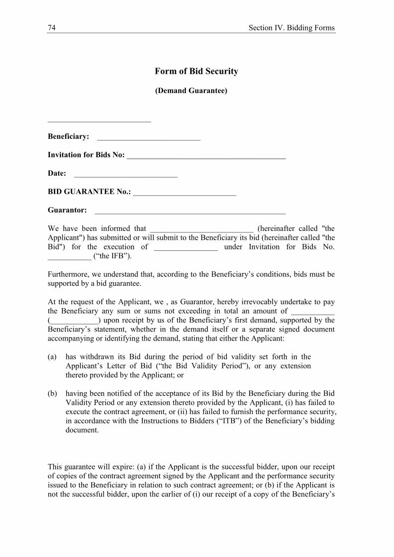
74 Section IV. Bidding Forms
Form of Bid Security
(Demand Guarantee)
__________________________
Beneficiary: __________________________
Invitation for Bids No: ________________________________________
Date: __________________________
BID GUARANTEE No.: __________________________
Guarantor: ________________________________________________
We have been informed that __________________________ (hereinafter called "the Applicant") has submitted or will submit to the Beneficiary its bid (hereinafter called "the Bid") for the execution of ________________ under Invitation for Bids No. ___________ (“the IFB”).
Furthermore, we understand that, according to the Beneficiary’s conditions, bids must be supported by a bid guarantee.
At the request of the Applicant, we , as Guarantor, hereby irrevocably undertake to pay the Beneficiary any sum or sums not exceeding in total an amount of ___________ (____________) upon receipt by us of the Beneficiary’s first demand, supported by the Beneficiary’s statement, whether in the demand itself or a separate signed document accompanying or identifying the demand, stating that either the Applicant:
(a) has withdrawn its Bid during the period of bid validity set forth in the Applicant’s Letter of Bid (“the Bid Validity Period”), or any extension thereto provided by the Applicant; or
(b) having been notified of the acceptance of its Bid by the Beneficiary during the Bid Validity Period or any extension thereto provided by the Applicant, (i) has failed to execute the contract agreement, or (ii) has failed to furnish the performance security, in accordance with the Instructions to Bidders (“ITB”) of the Beneficiary’s bidding document.
This guarantee will expire: (a) if the Applicant is the successful bidder, upon our receipt of copies of the contract agreement signed by the Applicant and the performance security issued to the Beneficiary in relation to such contract agreement; or (b) if the Applicant is not the successful bidder, upon the earlier of (i) our receipt of a copy of the Beneficiary’s
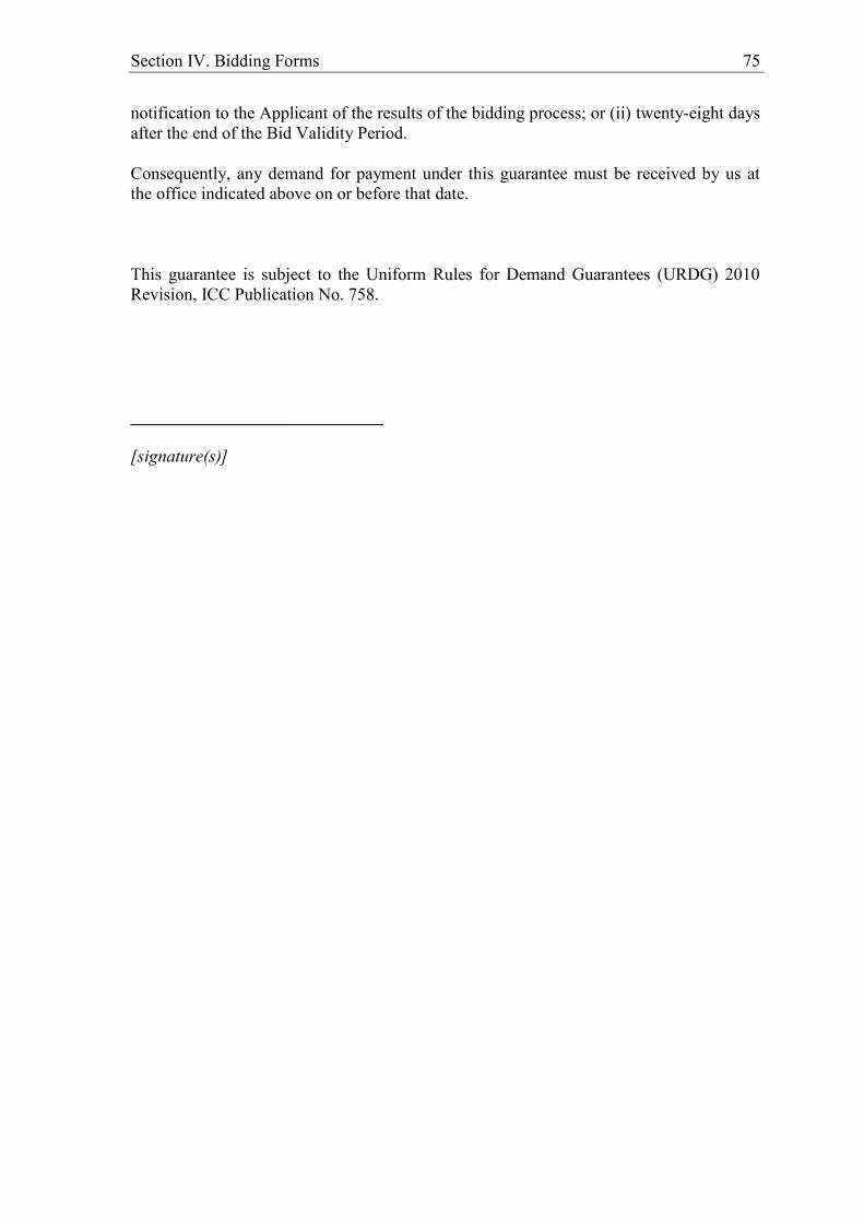
Section IV. Bidding Forms 75
notification to the Applicant of the results of the bidding process; or (ii) twenty-eight days after the end of the Bid Validity Period.
Consequently, any demand for payment under this guarantee must be received by us at the office indicated above on or before that date.
This guarantee is subject to the Uniform Rules for Demand Guarantees (URDG) 2010 Revision, ICC Publication No. 758.
_____________________________
[signature(s)]
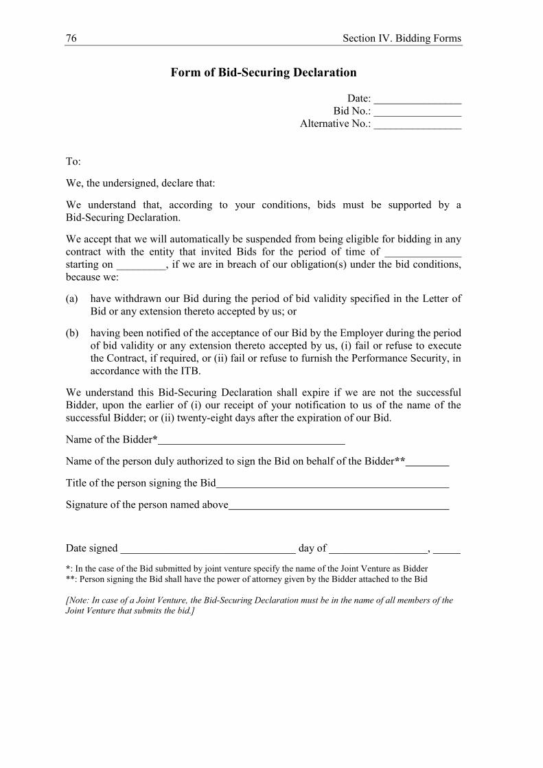
76 Section IV. Bidding Forms
Form of Bid-Securing Declaration
Date: ________________ Bid No.: ________________
Alternative No.: ________________
To:
We, the undersigned, declare that:
We understand that, according to your conditions, bids must be supported by a Bid-Securing Declaration.
We accept that we will automatically be suspended from being eligible for bidding in any contract with the entity that invited Bids for the period of time of ______________ starting on _________, if we are in breach of our obligation(s) under the bid conditions, because we:
(a) have withdrawn our Bid during the period of bid validity specified in the Letter of Bid or any extension thereto accepted by us; or
(b) having been notified of the acceptance of our Bid by the Employer during the period of bid validity or any extension thereto accepted by us, (i) fail or refuse to execute the Contract, if required, or (ii) fail or refuse to furnish the Performance Security, in accordance with the ITB.
We understand this Bid-Securing Declaration shall expire if we are not the successful Bidder, upon the earlier of (i) our receipt of your notification to us of the name of the successful Bidder; or (ii) twenty-eight days after the expiration of our Bid.
Name of the Bidder*
Name of the person duly authorized to sign the Bid on behalf of the Bidder**
Title of the person signing the Bid
Signature of the person named above
Date signed ________________________________ day of __________________, _____
*: In the case of the Bid submitted by joint venture specify the name of the Joint Venture as Bidder **: Person signing the Bid shall have the power of attorney given by the Bidder attached to the Bid [Note: In case of a Joint Venture, the Bid-Securing Declaration must be in the name of all members of the Joint Venture that submits the bid.]

Section V. Eligibility Criteria and Social and Environmental Responsibility 77
Section V. Eligibility Criteria and Social and Environmental Responsibility
Eligibility in AFD-Financed Procurement 1. Financing allocated by AFD has been entirely untied since 1st January 2002. To
the exception of any equipment or any sector which is subject to an embargo by the United Nations, the European Union or France, all goods and services are eligible for AFD financing regardless of the country of origin of the supplier, contractor, provider or sub-contractors, inputs or resources used in the implementation processes.
2. Natural or legal persons (including all members of a joint venture or any of their
subcontractors) shall not be awarded an AFD-financed contract if, on the date of submission of an application or of a bid or on the date of award of a contract, they:
i) are bankrupt or being wound up or ceasing their activities, are having
their activities administered by the courts, have entered into receivership, or are in any analogous situation arising from a similar procedure;
ii) have been convicted within the past five years by court decision, which
has the force of res judicata in the country where the project is implemented, of fraud or corruption or any other offence committed during the procurement or performance of a contract, unless they provide supporting information together with their Statement of Integrity (Form available as Appendix to Letter of Bid) which shows that this conviction is not relevant in the context of this AFD-financed project;
iii) are listed for financial sanctions by the United Nations, the European
Union and/or France for the purposes of fight against terrorist financing or threat to international peace and security;
iv) have committed serious professional misconduct within the past five years during the procurement or performance of a contract, as evidenced by any means by the Employer;
v) have not fulfilled their obligations regarding the payment of social security contributions or taxes in accordance with the legal provisions of the country where they are established or the Employer’s country;
vi) have been convicted within the past five years by court decision, which has the force of res judicata of fraud or corruption or any other offence committed in the context of an AFD-financed contract procurement or performance ;
vii) Are subject to an exclusion decision of the World Bank, since 30 May 2012, and are listed on the website http://www.worldbank.org/debarr,

78 Section V. Eligibility criteria and social and environmental responsibility
unless they provide supporting information together with their Statement of Integrity (Form available as Appendix to Letter of Bid) which shows that this exclusion is not relevant in the context of this AFD-financed project
viii) have committed misrepresentation in documentation requested by the Employer as part of the contract procurement procedure;
3. Bidders that are Government-owned enterprises or institutions may participate only
if they can establish that they (i) are legally and financially autonomous (ii) operate under commercial law. To be eligible, a government-owned enterprise or institution shall establish to the Agency’s satisfaction, through all relevant documents, including its Charter and other information the Agency may request, that it: (i) is a legal entity separate from their government (ii) does not currently receive substantial subsidies or budget support; (iii) operates like any commercial enterprise, and, inter alia, is not obliged to pass on its surplus to their government, can acquire rights and liabilities, borrow funds and be liable for repayment of its debts, and can be declared bankrupt.
4. In order to promote sustainable development, AFD seeks to ensure that
internationally recognised environmental and social standards are complied with. Candidates for AFD-financed contracts shall consequently undertake in the Statement of Integrity to: i) comply with and ensure that all their subcontractors comply with
international environmental and labour standards, consistent with applicable law and regulations in the country of implementation of the Project, including the fundamental conventions of the International Labour Organisation (ILO) and international environmental treaties;
ii) adopt any environmental and social risk mitigations measures as defined in the environmental and social management plan or in the environmental and social impact notice issued by the Employer.
Section VI. Agency Policy – Corrupt and Fraudulent Practices 79
Section VI. Agency Policy - Corrupt and Fraudulent Practices
The Employer, the Implementing Agency and the contractors, suppliers or consultants must observe the highest standard of ethics during contract procurement and performance. By signing the Statement of Integrity (form available as Appendix to Letter of Bid) the contractor, supplier or consultant declares that (i) “it did not engage in any practice likely to influence the contract award process to the Employer's detriment, and that it did not and will not get involved in any anti-competitive practice”, and that (ii) “the negotiation, the procurement and the performance of the contract did not and shall not give rise to any act of corruption or fraud”. Moreover, the Agency requires including in the Bidding Documents and Agency-financed contracts a provision requiring that bidders and contractors, suppliers and consultants will permit the Agency to inspect their accounts and records relating to the procurement and performance of the Agency-financed contract, and to have them audited by auditors appointed by the Agency. The Agency reserves the right to take any action it deems appropriate to check that these ethics rules are observed and reserves, in particular, the rights to:
reject a proposal for a contract award if it is established that during the selection process the bidder that is recommended for the award has been convicted of corruption, directly or by means of an agent, or has engaged in fraud or anti-competitive practices in view of being awarded the Contract;
declare misprocurement when it is established that, at any time, the Employer, the contractor, the supplier, the consultant or its representatives have engaged in acts of corruption, fraud or anti-competitive practices during the contract procurement or performance without the Employer having taken appropriate action in due time satisfactory to the Agency to remedy the situation, including by failing to inform the Agency at the time they knew of such practices.
The Agency defines, for the purposes of this provision, the terms set forth below as follows:
(a) Corruption of a public officer means:
the act of promising, offering or giving to a public officer, directly or indirectly, an undue advantage of any kind for himself or for another person or entity, for such public officer to act or refrain from acting in his official capacity; or
the act by which a public officer solicits or accepts, directly or indirectly, an undue advantage of any kind for himself or for another person or entity, for such public officer to act or refrain from acting in his official capacity.
(b) A "public officer" shall be construed as meaning:
any person who holds a legislative, executive, administrative or judicial mandate (within the State of the Employer) regardless of whether that

80 Section VI. Agency Policy – Corrupt and Fraudulent Practices
person was nominated or elected, regardless of the permanent or temporary, paid or unpaid nature of the position and regardless of the hierarchical level the person occupies;
any other person who performs a public function, including for a State institution or a State-owned company, or who provides a public service;
any other person defined as a public officer by the national laws of the Employer.
(c) Corruption of a private person means:
the act of promising, offering or giving to any person other than a public officer, directly or indirectly, an undue advantage of any kind for himself or for another person or entity, for such person to perform or refrain from performing any act in breach of its legal, contractual or professional obligations; or
the act by which any person other than a public officer solicits or accepts, directly or indirectly, an undue advantage of any kind for himself or for another person or entity, for such person to perform or refrain from performing any act in breach of its legal, contractual or professional obligations.
(d) Fraud means any dishonest conduct (act or omission), whether or not it constitutes a criminal offence, deliberately intended to deceive others, to intentionally conceal items, to violate or vitiate consent, to circumvent legal or regulatory requirements and/or to violate internal rules in order to obtain illegitimate profit.
(e) Anti-competitive practices means:
any concerted or implied practices which have as their object or effect the prevention, restriction or distortion of competition within a marketplace, especially where they (i) limit access to the marketplace or free exercise of competition by other undertakings, (ii) prevent free, competition-driven price determination by artificially causing price increases or decreases, (iii) restrict or control production, markets, investments or technical progress; or (iv) divide up market shares or sources of supply.
any abuse by one undertaking or a group of undertakings which hold a dominant position on an internal market or on a substantial part of it.
any practice whereby prices are quoted or set unreasonably low, the object of which is to eliminate an undertaking or any of its products from a market or to prevent it from entering the market.
81
PART 2 –WORKS REQUIREMENTS
82 Section VII. Works Requirements
Section VII. Works Requirements
Contents
Scope of Works .......................................................................................................................83
Technical Specifications ........................................................................................................85
Drawings .................................................................................................................................86
Supplementary Information .................................................................................................87
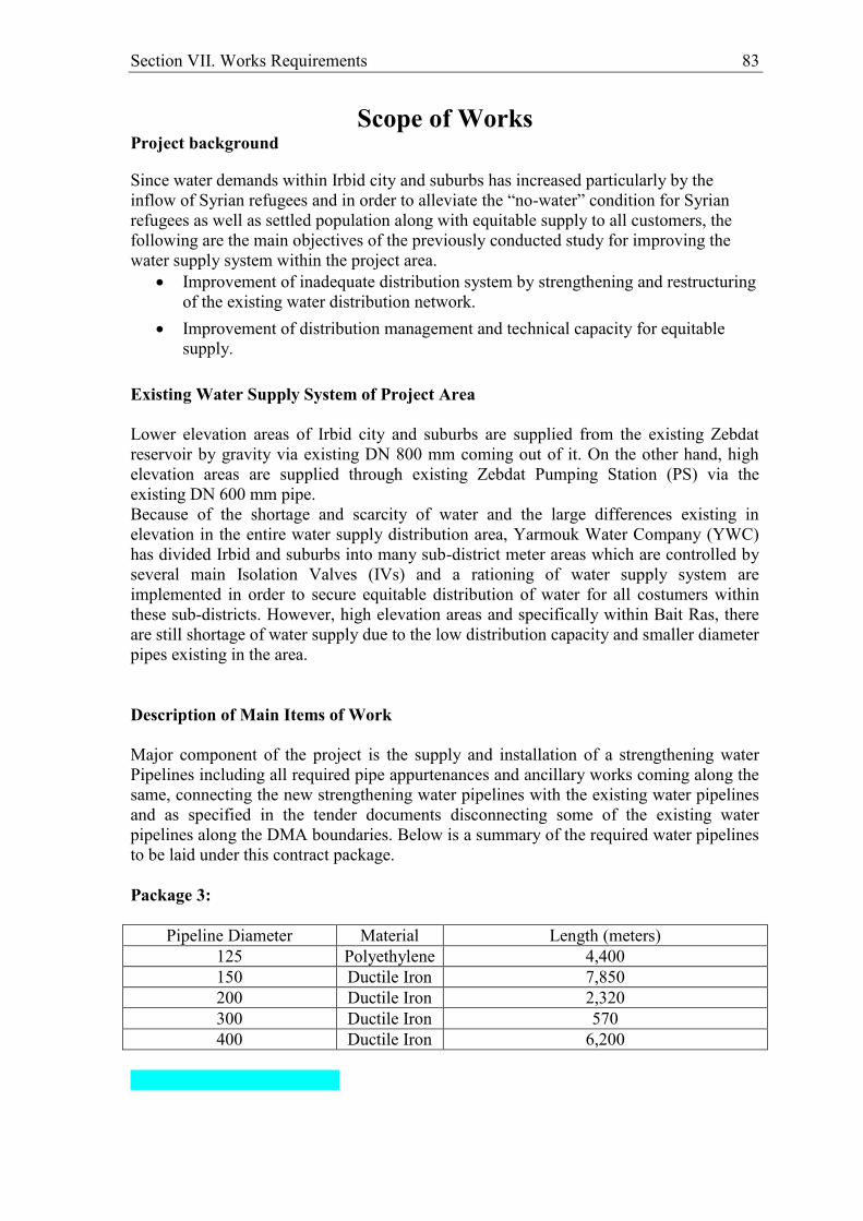
Section VII. Works Requirements 83
Scope of Works Project background
Since water demands within Irbid city and suburbs has increased particularly by the inflow of Syrian refugees and in order to alleviate the “no-water” condition for Syrian refugees as well as settled population along with equitable supply to all customers, the following are the main objectives of the previously conducted study for improving the water supply system within the project area.
Improvement of inadequate distribution system by strengthening and restructuring of the existing water distribution network.
Improvement of distribution management and technical capacity for equitable supply.
Existing Water Supply System of Project Area Lower elevation areas of Irbid city and suburbs are supplied from the existing Zebdat reservoir by gravity via existing DN 800 mm coming out of it. On the other hand, high elevation areas are supplied through existing Zebdat Pumping Station (PS) via the existing DN 600 mm pipe. Because of the shortage and scarcity of water and the large differences existing in elevation in the entire water supply distribution area, Yarmouk Water Company (YWC) has divided Irbid and suburbs into many sub-district meter areas which are controlled by several main Isolation Valves (IVs) and a rationing of water supply system are implemented in order to secure equitable distribution of water for all costumers within these sub-districts. However, high elevation areas and specifically within Bait Ras, there are still shortage of water supply due to the low distribution capacity and smaller diameter pipes existing in the area. Description of Main Items of Work Major component of the project is the supply and installation of a strengthening water Pipelines including all required pipe appurtenances and ancillary works coming along the same, connecting the new strengthening water pipelines with the existing water pipelines and as specified in the tender documents disconnecting some of the existing water pipelines along the DMA boundaries. Below is a summary of the required water pipelines to be laid under this contract package. Package 3:
Pipeline Diameter Material Length (meters) 125 Polyethylene 4,400 150 Ductile Iron 7,850 200 Ductile Iron 2,320 300 Ductile Iron 570 400 Ductile Iron 6,200

84 Section VII. Works Requirements

Section VII. Works Requirements 85
Technical Specifications
The detailed technical specification are provided in Volume II of this
tender package

86 Section VII. Works Requirements
Drawings The complete set of drawings are provided in volume IV of this tender package

Section VII. Works Requirements 87
Supplementary Information
The soil investigation report is provided in Appendix to the Technical
Specifications in Volume II of this tender package
88
PART 3 – CONDITIONS OF CONTRACT AND CONTRACT FORMS
Section VIII. General Conditions 89
Copyright FIDIC
Section VIII. General Conditions (GC)
1. General Provisions .................................................................................................... 95 1.1 Definitions ....................................................................................................... 95 1.2 Interpretation ................................................................................................. 101 1.3 Communications ........................................................................................... 101 1.4 Law and Language ........................................................................................ 102 1.5 Priority of Documents ................................................................................... 102 1.6 Contract Agreement ...................................................................................... 103 1.7 Assignment ................................................................................................... 103 1.8 Care and Supply of Documents .................................................................... 103 1.9 Delayed Drawings or Instructions ................................................................ 103 1.10 Employer’s Use of Contractor’s Documents ................................................ 104 1.11 Contractor’s Use of Employer’s Documents ................................................ 105 1.12 Confidential Details ...................................................................................... 105 1.13 Compliance with Laws ................................................................................. 106 1.14 Joint and Several Liability ............................................................................ 106 1.15 Inspections and Audit by the Bank ............................................................... 106
2. The Employer .......................................................................................................... 106 2.1 Right of Access to the Site ............................................................................ 106 2.2 Permits, Licences or Approvals .................................................................... 107 2.3 Employer’s Personnel ................................................................................... 108 2.4 Employer’s Financial Arrangements ............................................................ 108 2.5 Employer’s Claims ........................................................................................ 108
3. The Engineer ........................................................................................................... 109 3.1 Engineer’s Duties and Authority .................................................................. 109 3.2 Delegation by the Engineer ........................................................................... 111 3.3 Instructions of the Engineer .......................................................................... 111 3.4 Replacement of the Engineer ........................................................................ 112 3.5 Determinations .............................................................................................. 112
4. The Contractor ........................................................................................................ 113 4.1 Contractor’s General Obligations ................................................................. 113 4.2 Performance Security .................................................................................... 114 4.3 Contractor’s Representative .......................................................................... 115 4.4 Subcontractors ............................................................................................... 116 4.5 Assignment of Benefit of Subcontract .......................................................... 116 4.6 Co-operation ................................................................................................. 116 4.7 Setting Out .................................................................................................... 117 4.8 Safety Procedures .......................................................................................... 118 4.9 Quality Assurance ......................................................................................... 118 4.10 Site Data ........................................................................................................ 118 4.11 Sufficiency of the Accepted Contract Amount ............................................. 119 4.12 Unforeseeable Physical Conditions .............................................................. 119 4.13 Rights of Way and Facilities ......................................................................... 121
90 Section VIII. General Conditions
Copyright FIDIC
4.14 Avoidance of Interference ..............................................................................121 4.15 Access Route ..................................................................................................121 4.16 Transport of Goods ........................................................................................121 4.18 Protection of the Environment .......................................................................122 4.19 Electricity, Water and Gas .............................................................................122 4.22 Security of the Site .........................................................................................124 4.23 Contractor’s Operations on Site .....................................................................125 4.24 Fossils ............................................................................................................125
5. Nominated Subcontractors .....................................................................................126 5.1 Definition of “nominated Subcontractor” ......................................................126 5.2 Objection to Nomination................................................................................126 5.3 Payments to nominated Subcontractors .........................................................127 5.4 Evidence of Payments ....................................................................................127
6. Staff and Labour ......................................................................................................127 6.1 Engagement of Staff and Labour ...................................................................127 6.2 Rates of Wages and Conditions of Labour ....................................................128 6.3 Persons in the Service of Employer ...............................................................128 6.4 Labour Laws ..................................................................................................128 6.5 Working Hours...............................................................................................128 6.6 Facilities for Staff and Labour .......................................................................128 6.7 Health and Safety ...........................................................................................129 6.8 Contractor’s Superintendence ........................................................................130 6.9 Contractor’s Personnel ...................................................................................130 6.10 Records of Contractor’s Personnel and Equipment .......................................131 6.11 Disorderly Conduct ........................................................................................131 6.12 Foreign Personnel ..........................................................................................131 6.13 Supply of Foodstuffs ......................................................................................131 6.14 Supply of Water .............................................................................................131 6.15 Measures against Insect and Pest Nuisance ...................................................131 6.16 Alcoholic Liquor or Drugs .............................................................................131 6.17 Arms and Ammunition ..................................................................................132 6.18 Festivals and Religious Customs ...................................................................132 6.19 Funeral Arrangements ....................................................................................132 6.20 Prohibition of Forced or Compulsory Labour ...............................................132 6.21 Prohibition of Harmful Child Labour ............................................................132 6.22 Employment Records of Workers ..................................................................132 6.23 Workers’ Organisations .................................................................................132 6.24 Non-Discrimination and Equal Opportunity ..................................................133
7. Plant, Materials and Workmanship .......................................................................133 7.1 Manner of Execution......................................................................................133 7.2 Samples ..........................................................................................................133 7.3 Inspection .......................................................................................................134 7.4 Testing............................................................................................................134 7.5 Rejection ........................................................................................................135 7.6 Remedial Work ..............................................................................................135 7.7 Ownership of Plant and Materials..................................................................136 7.8 Royalties ........................................................................................................136
Section VIII. General Conditions 91
Copyright FIDIC
8. Commencement, Delays and Suspension .............................................................. 136 8.1 Commencement of Works ............................................................................ 136 8.2 Time for Completion ..................................................................................... 137 8.3 Programme .................................................................................................... 137 8.4 Extension of Time for Completion ............................................................... 138 8.5 Delays Caused by Authorities ....................................................................... 139 8.6 Rate of Progress ............................................................................................ 139 8.7 Delay Damages ............................................................................................. 140 8.8 Suspension of Work ...................................................................................... 140 8.9 Consequences of Suspension ........................................................................ 140 8.10 Payment for Plant and Materials in Event of Suspension ............................. 141 8.11 Prolonged Suspension ................................................................................... 141 8.12 Resumption of Work ..................................................................................... 141
9. Tests on Completion ............................................................................................... 141 9.1 Contractor’s Obligations ............................................................................... 141 9.2 Delayed Tests ................................................................................................ 142 9.3 Retesting ....................................................................................................... 142 9.4 Failure to Pass Tests on Completion ............................................................. 142
10. Employer’s Taking Over ........................................................................................ 143 10.1 Taking Over of the Works and Sections ....................................................... 143 10.2 Taking Over of Parts of the Works ............................................................... 144 10.3 Interference with Tests on Completion ......................................................... 145
11. Defects Liability ...................................................................................................... 145 11.1 Completion of Outstanding Work and Remedying Defects ......................... 145 11.2 Cost of Remedying Defects .......................................................................... 146 11.3 Extension of Defects Notification Period ..................................................... 146 11.4 Failure to Remedy Defects ............................................................................ 147 11.5 Removal of Defective Work ......................................................................... 147 11.6 Further Tests ................................................................................................. 147 11.7 Right of Access ............................................................................................. 148 11.8 Contractor to Search ..................................................................................... 148 11.9 Performance Certificate ................................................................................ 148 11.10 Unfulfilled Obligations ................................................................................. 148 11.11 Clearance of Site ........................................................................................... 148
12. Measurement and Evaluation ................................................................................ 149 12.1 Works to be Measured .................................................................................. 149 12.2 Method of Measurement ............................................................................... 149 12.3 Evaluation ..................................................................................................... 150 12.4 Omissions ...................................................................................................... 151
13. Variations and Adjustments .................................................................................. 151 13.1 Right to Vary ................................................................................................. 151 13.2 Value Engineering ........................................................................................ 152 13.3 Variation Procedure ...................................................................................... 153 13.4 Payment in Applicable Currencies ................................................................ 153 13.5 Provisional Sums .......................................................................................... 154 13.6 Daywork ........................................................................................................ 154
92 Section VIII. General Conditions
Copyright FIDIC
13.7 Adjustments for Changes in Legislation ........................................................155 13.8 Adjustments for Changes in Cost ..................................................................156
14. Contract Price and Payment ...................................................................................157 14.1 The Contract Price .........................................................................................157 14.2 Advance Payment ..........................................................................................158 14.3 Application for Interim Payment Certificates ................................................159 14.4 Schedule of Payments ....................................................................................160 14.5 Plant and Materials intended for the Works ..................................................161 14.6 Issue of Interim Payment Certificates ............................................................162 14.7 Payment..........................................................................................................163 14.8 Delayed Payment ...........................................................................................163 14.9 Payment of Retention Money ........................................................................164 14.10 Statement at Completion ................................................................................165 14.11 Application for Final Payment Certificate .....................................................165 14.12 Discharge 166 14.13 Issue of Final Payment Certificate .................................................................166 14.14 Cessation of Employer’s Liability .................................................................167 14.15 Currencies of Payment ...................................................................................167
15. Termination by Employer .......................................................................................168 15.1 Notice to Correct ............................................................................................168 15.2 Termination by Employer ..............................................................................168 15.3 Valuation at Date of Termination ..................................................................170 15.4 Payment after Termination ............................................................................170 15.5 Employer’s Entitlement to Termination for Convenience .............................170 15.6 Corrupt or Fraudulent Practices .....................................................................170
16. Suspension and Termination by Contractor .........................................................172 16.1 Contractor’s Entitlement to Suspend Work ...................................................172 16.2 Termination by Contractor .............................................................................173 16.3 Cessation of Work and Removal of Contractor’s Equipment .......................174 16.4 Payment on Termination ................................................................................174
17. Risk and Responsibility ...........................................................................................175 17.1 Indemnities .....................................................................................................175 17.2 Contractor’s Care of the Works .....................................................................175 17.3 Employer’s Risks ...........................................................................................176 17.4 Consequences of Employer’s Risks ...............................................................177 17.5 Intellectual and Industrial Property Rights ....................................................177 17.6 Limitation of Liability....................................................................................178 17.7 Use of Employer’s Accomodation/Facilities .................................................179
18. Insurance ..................................................................................................................179 18.1 General Requirements for Insurances ............................................................179 18.2 Insurance for Works and Contractor’s Equipment ........................................181 18.3 Insurance against Injury to Persons and Damage to Property .......................183 18.4 Insurance for Contractor’s Personnel .............................................................183
19. Force Majeure ..........................................................................................................184 19.1 Definition of Force Majeure ..........................................................................184
Section VIII. General Conditions 93
Copyright FIDIC
19.3 Duty to Minimise Delay ................................................................................ 185 19.4 Consequences of Force Majeure ................................................................... 185 19.5 Force Majeure Affecting Subcontractor ....................................................... 186 19.6 Optional Termination, Payment and Release ................................................ 186 19.7 Release from Performance ............................................................................ 186
20. Claims, Disputes and Arbitration .......................................................................... 187 20.1 Contractor’s Claims ...................................................................................... 187 20.2 Appointment of the Dispute Board ............................................................... 189 20.3 Failure to Agree on the Composition of the Dispute Board ......................... 190 20.4 Obtaining Dispute Board’s Decision ............................................................ 190 20.5 Amicable Settlement ..................................................................................... 191 20.6 Arbitration ..................................................................................................... 192 20.7 Failure to Comply with Dispute Board’s Decision ....................................... 193 20.8 Expiry of Dispute Board’s Appointment ...................................................... 193

94 Section VIII. General Conditions
Copyright FIDIC
Section VIII. General Conditions (GC)
[Name of Employer]
[Name of Contract]
The General Conditions that follow are the Agency Harmonized Edition of the Conditions of Contract for Construction prepared and copyrighted by the International Federation of Consulting Engineers (Fédération Internationale des Ingénieurs-Conseils, or FIDIC), FIDIC 2010-All rights reserved. This publication is exclusive for the use of Agency’s Beneficiaries and their project implementing agencies as provided under the License Agreement dated September 21st, 2009, between the Agence Française de Développement and FIDIC, and, consequently, no part of this publication may be reproduced, translated, adapted, stored in a retrieval system or communicated, in any form or by any means, whether mechanical, electronic, magnetic, photocopying, recording or otherwise, without prior permission in writing from FIDIC, except by the Employer identified above and only for the exclusive purpose of preparing these Standard Bidding Documents for the Contract also identified above.
Section VIII. General Conditions 95
Copyright FIDIC
General Conditions 1. General Provisions
1.1 Definitions In the Conditions of Contract (“these Conditions”), which include Particular Conditions, Parts A and B, and these General Conditions, the following words and expressions shall have the meanings stated. Words indicating persons or parties include corporations and other legal entities, except where the context requires otherwise.
1.1.1 The Contract 1.1.1.1 “Contract” means the Contract Agreement, the Letter of Acceptance, the Letter of Tender, these Conditions, the Specification, the Drawings, the Schedules, and the further documents (if any) which are listed in the Contract Agreement or in the Letter of Acceptance.
1.1.1.2 “Contract Agreement” means the contract agreement referred to in Sub-Clause 1.6 [Contract Agreement].
1.1.1.3 “Letter of Acceptance” means the letter of formal acceptance, signed by the Employer, of the Letter of Tender, including any annexed memoranda comprising agreements between and signed by both Parties. If there is no such letter of acceptance, the expression “Letter of Acceptance” means the Contract Agreement and the date of issuing or receiving the Letter of Acceptance means the date of signing the Contract Agreement.
1.1.1.4 “Letter of Tender” means the document entitled letter of tender or letter of bid, which was completed by the Contractor and includes the signed offer to the Employer for the Works.
1.1.1.5 “Specification” means the document entitled specification, as included in the Contract, and any additions and modifications to the specification in accordance with the Contract. Such document specifies the Works.
1.1.1.6 “Drawings” means the drawings of the Works, as included in the Contract, and any additional and modified drawings issued by (or on behalf of) the Employer in accordance with the Contract.
1.1.1.7 “Schedules” means the document(s) entitled schedules, completed by the Contractor and submitted with the Letter of Tender, as included in the Contract. Such document may include the Bill
96 Section VIII. General Conditions
Copyright FIDIC
of Quantities, data, lists, and schedules of rates and/or prices.
1.1.1.8 “Tender” means the Letter of Tender and all other documents which the Contractor submitted with the Letter of Tender, as included in the Contract.
1.1.1.9 “Bill of Quantities”, “Daywork Schedule” and “Schedule of Payment Currencies” mean the documents so named (if any) which are comprised in the Schedules.
1.1.1.10 “Contract Data” means the pages completed by the Employer entitled contract data which constitute Part A of the Particular Conditions.
1.1.2 Parties and Persons
1.1.2.1 “Party” means the Employer or the Contractor, as the context requires.
1.1.2.2 “Employer” means the person named as employer in the Contract Data and the legal successors in title to this person.
1.1.2.3 “Contractor” means the person(s) named as contractor in the Letter of Tender accepted by the Employer and the legal successors in title to this person(s).
1.1.2.4 “Engineer” means the person appointed by the Employer to act as the Engineer for the purposes of the Contract and named in the Contract Data, or other person appointed from time to time by the Employer and notified to the Contractor under Sub-Clause 3.4 [Replacement of the Engineer].
1.1.2.5 “Contractor’s Representative” means the person named by the Contractor in the Contract or appointed from time to time by the Contractor under Sub-Clause 4.3 [Contractor’s Representative], who acts on behalf of the Contractor.
1.1.2.6 “Employer’s Personnel” means the Engineer, the assistants referred to in Sub-Clause 3.2 [Delegation by the Engineer] and all other staff, labour and other employees of the Engineer and of the Employer; and any other personnel notified to the Contractor, by the Employer or the Engineer, as Employer’s Personnel.
1.1.2.7 “Contractor’s Personnel” means the Contractor’s Representative and all personnel whom the Contractor utilises on Site, who may include the
Section VIII. General Conditions 97
Copyright FIDIC
staff, labour and other employees of the Contractor and of each Subcontractor; and any other personnel assisting the Contractor in the execution of the Works.
1.1.2.8 “Subcontractor” means any person named in the Contract as a subcontractor, or any person appointed as a subcontractor, for a part of the Works; and the legal successors in title to each of these persons.
1.1.2.9 “DB” means the person or three persons appointed under Sub-Clause 20.2 [Appointment of the Dispute Board] or Sub-Clause 20.3 [Failure to Agree on the Composition of the Dispute Board]
1.1.2.10 “FIDIC” means the Fédération Internationale des Ingénieurs-Conseils, the international federation of consulting engineers.
1.1.2.11 “Bank” means the financing institution (if any) named in the Contract Data.
1.1.2.12 “Borrower” means the person (if any) named as the borrower in the Contract Data.
1.1.3 Dates, Tests, Periods and Completion
1.1.3.1 “Base Date” means the date 28 days prior to the latest date for submission of the Tender.
1.1.3.2 “Commencement Date” means the date notified under Sub-Clause 8.1 [Commencement of Works].
1.1.3.3 “Time for Completion” means the time for completing the Works or a Section (as the case may be) under Sub-Clause 8.2 [Time for Completion], as stated in the Contract Data (with any extension under Sub-Clause 8.4 [Extension of Time for Completion]), calculated from the Commencement Date.
1.1.3.4 “Tests on Completion” means the tests which are specified in the Contract or agreed by both Parties or instructed as a Variation, and which are carried out under Clause 9 [Tests on Completion] before the Works or a Section (as the case may be) are taken over by the Employer.
1.1.3.5 “Taking-Over Certificate” means a certificate issued under Clause 10 [Employer’s Taking Over].
1.1.3.6 “Tests after Completion” means the tests (if any) which are specified in the Contract and which are carried out in accordance with the Specification
98 Section VIII. General Conditions
Copyright FIDIC
after the Works or a Section (as the case may be) are taken over by the Employer.
1.1.3.7 “Defects Notification Period” means the period for notifying defects in the Works or a Section (as the case may be) under Sub-Clause 11.1 [Completion of Outstanding Work and Remedying Defects], which extends over 365 days except if otherwise stated in the Contract Data (with any extension under Sub-Clause 11.3 [Extension of Defects Notification Period]), calculated from the date on which the Works or Section is completed as certified under Sub-Clause 10.1 [Taking Over of the Works and Sections]..
1.1.3.8 “Performance Certificate” means the certificate issued under Sub-Clause 11.9 [Performance Certificate]..
1.1.3.9 “Day” means a calendar day and “year” means 365 days.
1.1.4 Money and Payments
1.1.4.1 “Accepted Contract Amount” means the amount accepted in the Letter of Acceptance for the execution and completion of the Works and the remedying of any defects.
1.1.4.2 “Contract Price” means the price defined in Sub-Clause 14.1 [The Contract Price], and includes adjustments in accordance with the Contract.
1.1.4.3 “Cost” means all expenditure reasonably incurred (or to be incurred) by the Contractor, whether on or off the Site, including overhead and similar charges, but does not include profit.
1.1.4.4 “Final Payment Certificate” means the payment certificate issued under Sub-Clause 14.13 [Issue of Final Payment Certificate].
1.1.4.5 “Final Statement” means the statement defined in Sub-Clause 14.11 [Application for Final Payment Certificate].
1.1.4.6 “Foreign Currency” means a currency in which part (or all) of the Contract Price is payable, but not the Local Currency.
1.1.4.7 “Interim Payment Certificate” means a payment certificate issued under Clause 14 [Contract Price and Payment], other than the Final Payment Certificate.
1.1.4.8 “Local Currency” means the currency of the
Section VIII. General Conditions 99
Copyright FIDIC
Country.
1.1.4.9 “Payment Certificate” means a payment certificate issued under Clause 14 [Contract Price and Payment].
1.1.4.10 “Provisional Sum” means a sum (if any) which is specified in the Contract as a provisional sum, for the execution of any part of the Works or for the supply of Plant, Materials or services under Sub-Clause 13.5 [Provisional Sums]..
1.1.4.11 “Retention Money” means the accumulated retention moneys which the Employer retains under Sub-Clause 14.3 [Application for Interim Payment Certificates] and pays under Sub-Clause 14.9 [Payment of Retention Money].
1.1.4.12 “Statement” means a statement submitted by the Contractor as part of an application, under Clause 14 [Contract Price and Payment], for a payment certificate.
1.1.5 Works and Goods
1.1.5.1 “Contractor’s Equipment” means all apparatus, machinery, vehicles and other things required for the execution and completion of the Works and the remedying of any defects. However, Contractor’s Equipment excludes Temporary Works, Employer’s Equipment (if any), Plant, Materials and any other things intended to form or forming part of the Permanent Works.
1.1.5.2 “Goods” means Contractor’s Equipment, Materials, Plant and Temporary Works, or any of them as appropriate.
1.1.5.3 “Materials” means things of all kinds (other than Plant) intended to form or forming part of the Permanent Works, including the supply-only materials (if any) to be supplied by the Contractor under the Contract.
1.1.5.4 “Permanent Works” means the permanent works to be executed by the Contractor under the Contract.
1.1.5.5 “Plant” means the apparatus, machinery and other equipment intended to form or forming part of the Permanent Works, including vehicles purchased for the Employer and relating to the construction or operation of the Works.
1.1.5.6 “Section” means a part of the Works specified in the Contract Data as a Section (if any).1.1.5.7
100 Section VIII. General Conditions
Copyright FIDIC
“Temporary Works” means all temporary works of every kind (other than Contractor’s Equipment) required on Site for the execution and completion of the Permanent Works and the remedying of any defects.
1.1.5.8 “Works” mean the Permanent Works and the Temporary Works, or either of them as appropriate.
1.1.6 Other Definitions 1.1.6.1 “Contractor’s Documents” means the calculations, computer programs and other software, drawings, manuals, models and other documents of a technical nature (if any) supplied by the Contractor under the Contract.
1.1.6.2 “Country” means the country in which the Site (or most of it) is located, where the Permanent Works are to be executed.
1.1.6.3 “Employer’s Equipment” means the apparatus, machinery and vehicles (if any) made available by the Employer for the use of the Contractor in the execution of the Works, as stated in the Specification; but does not include Plant which has not been taken over by the Employer.
1.1.6.4 “Force Majeure” is defined in Clause 19 [Force Majeure]..
1.1.6.5 “Laws” means all national (or state) legislation, statutes, ordinances and other laws, and regulations and by-laws of any legally constituted public authority.
1.1.6.6 “Performance Security” means the security (or securities, if any) under Sub-Clause 4.2 [Performance Security]..
1.1.6.7 “Site” means the places where the Permanent Works are to be executed, including storage and working areas, and to which Plant and Materials are to be delivered, and any other places as may be specified in the Contract as forming part of the Site.
1.1.6.8 “Unforeseeable” means not reasonably foreseeable by an experienced contractor by the Base Date.
1.1.6.9 “Variation” means any change to the Works, which is instructed or approved as a variation under Clause 13 [Variations and Adjustments].
1.1.6.10 “Notice of Dissatisfaction” means the notice
Section VIII. General Conditions 101
Copyright FIDIC
given by either Party to the other under Sub-Clause 20.4 [Obtaining Dispute Board’s Decision] indicating its dissatisfaction and intention to commence arbitration.
1.2 Interpretation In the Contract, except where the context requires otherwise:
(a) words indicating one gender include all genders;
(b) words indicating the singular also include the plural and words indicating the plural also include the singular;
(c) provisions including the word “agree”, “agreed” or “agreement” require the agreement to be recorded in writing;
(d) “written” or “in writing” means hand-written, type-written, printed or electronically made, and resulting in a permanent record; and
(e) the word “tender” is synonymous with “bid” and “tenderer” with “bidder” and the words “tender documents” with “bidding documents
The marginal words and other headings shall not be taken into consideration in the interpretation of these Conditions.
In these Conditions, provisions including the expression "Cost plus profit" require this profit to be one-twentieth (5%) of this Cost unless otherwise indicated in the Contract Data.
1.3 Communications
Wherever these Conditions provide for the giving or issuing of approvals, certificates, consents, determinations, notices, requests and discharges, these communications shall be:
(a) in writing and delivered by hand (against receipt), sent by mail or courier, or transmitted using any of the agreed systems of electronic transmission as stated in the Contract Data; and
(b) delivered, sent or transmitted to the address for the recipient’s communications as stated in the Contract Data. However:
(i) if the recipient gives notice of another address, communications shall thereafter be delivered accordingly; and
(ii) if the recipient has not stated otherwise when
102 Section VIII. General Conditions
Copyright FIDIC
requesting an approval or consent, it may be sent to the address from which the request was issued.
Approvals, certificates, consents and determinations shall not be unreasonably withheld or delayed. When a certificate is issued to a Party, the certifier shall send a copy to the other Party. When a notice is issued to a Party, by the other Party or the Engineer, a copy shall be sent to the Engineer or the other Party, as the case may be.
1.4 Law and Language
The Contract shall be governed by the law of the country or other jurisdiction stated in the Contract Data.
The ruling language of the Contract shall be that stated in the Contract Data.
The language for communications shall be that stated in the Contract Data. If no language is stated there, the language for communications shall be the ruling language of the Contract.
1.5 Priority of Documents
The documents forming the Contract are to be taken as mutually explanatory of one another. For the purposes of interpretation, the priority of the documents shall be in accordance with the following sequence:
(a) the Contract Agreement (if any),
(b) the Letter of Acceptance,
(c) the Letter of Tender,
(d) the Particular Conditions – Part A,
(e) the Particular Conditions – Part B
(f) these General Conditions
(g) the Specification,
(h) the Drawings, and
(i) the Schedules and any other documents forming part of the Contract.
If an ambiguity or discrepancy is found in the documents, the Engineer shall issue any necessary clarification or instruction.
Section VIII. General Conditions 103
Copyright FIDIC
1.6 Contract Agreement
The Parties shall enter into a Contract Agreement within 28 days after the Contractor receives the Letter of Acceptance, unless the Particular Conditions establish otherwise. The Contract Agreement shall be based upon the form annexed to the Particular Conditions. The costs of stamp duties and similar charges (if any) imposed by law in connection with entry into the Contract Agreement shall be borne by the Employer.
1.7 Assignment Neither Party shall assign the whole or any part of the Contract or any benefit or interest in or under the Contract. However, either Party:
(a) may assign the whole or any part with the prior agreement of the other Party, at the sole discretion of such other Party, and
(b) may, as security in favour of a bank or financial institution, assign its right to any moneys due, or to become due, under the Contract.
1.8 Care and Supply of Documents
The Specification and Drawings shall be in the custody and care of the Employer. Unless otherwise stated in the Contract, two copies of the Contract and of each subsequent Drawing shall be supplied to the Contractor, who may make or request further copies at the cost of the Contractor.
Each of the Contractor’s Documents shall be in the custody and care of the Contractor, unless and until taken over by the Employer. Unless otherwise stated in the Contract, the Contractor shall supply to the Engineer six copies of each of the Contractor’s Documents.
The Contractor shall keep, on the Site, a copy of the Contract, publications named in the Specification, the Contractor’s Documents (if any), the Drawings and Variations and other communications given under the Contract. The Employer’s Personnel shall have the right of access to all these documents at all reasonable times.
If a Party becomes aware of an error or defect in a document which was prepared for use in executing the Works, the Party shall promptly give notice to the other Party of such error or defect.
1.9 Delayed Drawings or Instructions
The Contractor shall give notice to the Engineer whenever the Works are likely to be delayed or disrupted if any necessary drawing or instruction is not issued to the Contractor within a particular time, which shall be reasonable. The notice shall include details of the necessary drawing or instruction, details of why and by when it should be issued, and the nature and amount of the delay or
104 Section VIII. General Conditions
Copyright FIDIC
disruption likely to be suffered if it is late.
If the Contractor suffers delay and/or incurs Cost as a result of a failure of the Engineer to issue the notified drawing or instruction within a time which is reasonable and is specified in the notice with supporting details, the Contractor shall give a further notice to the Engineer and shall be entitled subject to Sub-Clause 20.1 [Contractor’s Claims] to:
(a) an extension of time for any such delay, if completion is or will be delayed, under Sub-Clause 8.4 [Extension of Time for Completion], and
(b) payment of any such Cost plus profit, which shall be included in the Contract Price.
After receiving this further notice, the Engineer shall proceed in accordance with Sub-Clause 3.5 [Determinations] to agree or determine these matters.
However, if and to the extent that the Engineer’s failure was caused by any error or delay by the Contractor, including an error in, or delay in the submission of, any of the Contractor’s Documents, the Contractor shall not be entitled to such extension of time, Cost or profit.
1.10 Employer’s Use of Contractor’s Documents
As between the Parties, the Contractor shall retain the copyright and other intellectual property rights in the Contractor’s Documents and other design documents made by (or on behalf of) the Contractor.
The Contractor shall be deemed (by signing the Contract) to give to the Employer a non-terminable transferable non-exclusive royalty-free licence to copy, use and communicate the Contractor’s Documents, including making and using modifications of them. This licence shall:
(a) apply throughout the actual or intended working life (whichever is longer) of the relevant parts of the Works,
(b) entitle any person in proper possession of the relevant part of the Works to copy, use and communicate the Contractor’s Documents for the purposes of completing, operating, maintaining, altering, adjusting, repairing and demolishing the Works, and
(c) in the case of Contractor’s Documents which are in the form of computer programs and other software, permit their use on any computer on the Site and other places as envisaged by the Contract, including replacements
Section VIII. General Conditions 105
Copyright FIDIC
of any computers supplied by the Contractor.
The Contractor’s Documents and other design documents made by (or on behalf of) the Contractor shall not, without the Contractor’s consent, be used, copied or communicated to a third party by (or on behalf of) the Employer for purposes other than those permitted under this Sub-Clause.
1.11 Contractor’s Use of Employer’s Documents
As between the Parties, the Employer shall retain the copyright and other intellectual property rights in the Specification, the Drawings and other documents made by (or on behalf of) the Employer. The Contractor may, at his cost, copy, use, and obtain communication of these documents for the purposes of the Contract. They shall not, without the Employer’s consent, be copied, used or communicated to a third party by the Contractor, except as necessary for the purposes of the Contract.
1.12 Confidential Details
The Contractor’s and the Employer’s Personnel shall disclose all such confidential and other information as may be reasonably required in order to verify compliance with the Contract and allow its proper implementation.
Each of them shall treat the details of the Contract as private and confidential, except to the extent necessary to carry out their respective obligations under the Contract or to comply with applicable Laws. Each of them shall not publish or disclose any particulars of the Works prepared by the other Party without the previous agreement of the other Party. However, the Contractor shall be permitted to disclose any publicly available information, or information otherwise required to establish his qualifications to compete for other projects.
106 Section VIII. General Conditions
Copyright FIDIC
1.13 Compliance with Laws
The Contractor shall, in performing the Contract, comply with applicable Laws. Unless otherwise stated in the Particular Conditions:
(a) the Employer shall have obtained (or shall obtain) the planning, zoning, building permit or similar permission for the Permanent Works, and any other permissions described in the Specification as having been (or to be) obtained by the Employer; and the Employer shall indemnify and hold the Contractor harmless against and from the consequences of any failure to do so; and
(b) the Contractor shall give all notices, pay all taxes, duties and fees, and obtain all permits, licences and approvals, as required by the Laws in relation to the execution and completion of the Works and the remedying of any defects; and the Contractor shall indemnify and hold the Employer harmless against and from the consequences of any failure to do so, unless the Contractor is impeded to accomplish these actions and shows evidence of its diligence.
1.14 Joint and Several Liability
If the Contractor constitutes (under applicable Laws) a joint venture, consortium or other unincorporated grouping of two or more persons:
(a) these persons shall be deemed to be jointly and severally liable to the Employer for the performance of the Contract;
(b) these persons shall notify the Employer of their leader who shall have authority to bind the Contractor and each of these persons; and
(c) the Contractor shall not alter its composition or legal status without the prior consent of the Employer.
1.15 Inspections and Audit by the Bank
The Contractor shall permit the Bank and/or persons appointed by the Bank to inspect the Site and/or the Contractor’s accounts and records relating to the performance of the Contract and to have such accounts and records audited by auditors appointed by the Bank if required by the Bank.
2. The Employer
2.1 Right of Access to the Site
The Employer shall give the Contractor right of access to, and possession of, all parts of the Site within the time (or times) stated in the Contract Data. The right and possession may not be exclusive to the Contractor. If, under the Contract, the Employer is required to give (to the
Section VIII. General Conditions 107
Copyright FIDIC
Contractor) possession of any foundation, structure, plant or means of access, the Employer shall do so in the time and manner stated in the Specification. However, the Employer may withhold any such right or possession until the Performance Security has been received.
If no such time is stated in the Contract Data, the Employer shall give the Contractor right of access to, and possession of, the Site within such times as required to enable the Contractor to proceed without disruption in accordance with the programme submitted under Sub-Clause 8.3 [Programme].
If the Contractor suffers delay and/or incurs Cost as a result of a failure by the Employer to give any such right or possession within such time, the Contractor shall give notice to the Engineer and shall be entitled subject to Sub-Clause 20.1 [Contractor’s Claims] to:
(a) an extension of time for any such delay, if completion is or will be delayed, under Sub-Clause 8.4 [Extension of Time for Completion], and
(b) payment of any such Cost plus profit, which shall be included in the Contract Price.
After receiving this notice, the Engineer shall proceed in accordance with Sub-Clause 3.5 [Determinations] to agree or determine these matters.
However, if and to the extent that the Employer’s failure was caused by any error or delay by the Contractor, including an error in, or delay in the submission of, any of the Contractor’s Documents, the Contractor shall not be entitled to such extension of time, Cost or profit.
2.2 Permits, Licences or Approvals
The Employer shall provide, at the request of the Contractor, such reasonable assistance as to allow the Contractor to obtain properly:
(a) copies of the Laws of the Country which are relevant to the Contract but are not readily available, and
(b) any permits, licences or approvals required by the Laws of the Country:
(i) which the Contractor is required to obtain under Sub-Clause 1.13 [Compliance with Laws],
(ii) for the delivery of Goods, including clearance through customs, and
(iii) for the export of Contractor’s Equipment when it is removed from the Site.
108 Section VIII. General Conditions
Copyright FIDIC
2.3 Employer’s Personnel
The Employer shall be responsible for ensuring that the Employer’s Personnel and the Employer’s other contractors on the Site:
(a) co-operate with the Contractor’s efforts under Sub-Clause 4.6 [Co-operation], and
(b) take actions similar to those which the Contractor is required to take under sub-paragraphs (a), (b) and (c) of Sub-Clause 4.8 [Safety Procedures] and under Sub-Clause 4.18 [Protection of the Environment].
2.4 Employer’s Financial Arrangements
The Employer shall submit, before the Commencement Date and thereafter within 28 days after receiving any request from the Contractor, reasonable evidence that financial arrangements have been made and are being maintained which will enable the Employer to pay the Contract Price punctually (as estimated at that time) in accordance with Clause 14 [Contract Price and Payment]. Before the Employer makes any material change to his financial arrangements, the Employer shall give notice to the Contractor with detailed particulars.
In addition, if the Bank has notified to the Borrower that the Bank has suspended disbursements under its loan, which finances in whole or in part the execution of the Works, the Employer shall give notice of such suspension to the Contractor with detailed particulars, including the date of such notification, with a copy to the Engineer, within 7 days of the Borrower having received the suspension notification from the Bank. If alternative funds will be available in appropriate currencies to the Employer to continue making payments to the Contractor beyond a date 60 days after the date of Bank notification of the suspension, the Employer shall provide reasonable evidence in his notice of the extent to which such funds will be available.
2.5 Employer’s Claims
If the Employer considers himself to be entitled to any payment under any Clause of these Conditions or otherwise in connection with the Contract, and/or to any extension of the Defects Notification Period, the Employer or the Engineer shall give notice and particulars to the Contractor. However, notice is not required for payments due under Sub-Clause 4.19 [Electricity, Water and Gas], under Sub-Clause 4.20 [Employer’s Equipment and Free-Issue Materials], or for other services requested by the Contractor.
The notice shall be given as soon as practicable and no longer than 28 days after the Employer became aware, or should have become aware, of the event or circumstances giving rise to the claim. A notice relating to any extension of the Defects Notification Period shall be given before the
Section VIII. General Conditions 109
Copyright FIDIC
expiry of such period.
The particulars shall specify the Clause or other basis of the claim, and shall include substantiation of the amount and/or extension to which the Employer considers himself to be entitled in connection with the Contract. The Engineer shall then proceed in accordance with Sub-Clause 3.5 [Determinations] to agree or determine (i) the amount (if any) which the Employer is entitled to be paid by the Contractor, and/or (ii) the extension (if any) of the Defects Notification Period in accordance with Sub-Clause 11.3 [Extension of Defects Notification Period].
This amount may be included as a deduction in the Contract Price and Payment Certificates. The Employer shall only be entitled to set off against or make any deduction from an amount certified in a Payment Certificate, or to otherwise claim against the Contractor, in accordance with this Sub-Clause.
3. The Engineer
3.1 Engineer’s Duties and Authority
The Employer shall appoint the Engineer who shall carry out the duties assigned to him in the Contract. The Engineer’s staff shall include suitably qualified engineers and other professionals who are competent to carry out these duties.
The Engineer shall have no authority to amend the Contract.
The Engineer may exercise the authority attributable to the Engineer as specified in or necessarily to be implied from the Contract. If the Engineer is required to obtain the approval of the Employer before exercising a specified authority, the requirements shall be as stated in the Particular Conditions. The Employer shall promptly inform the Contractor of any change to the authority attributed to the Engineer.
However, whenever the Engineer exercises a specified authority for which the Employer’s approval is required, then (for the purposes of the Contract) the Employer shall be deemed to have given approval.
Except as otherwise stated in these Conditions:
(a) whenever carrying out duties or exercising authority, specified in or implied by the Contract, the Engineer shall be deemed to act for the Employer;
(b) the Engineer has no authority to relieve either Party of any duties, obligations or responsibilities under the Contract;
110 Section VIII. General Conditions
Copyright FIDIC
(c) any approval, check, certificate, consent, examination, inspection, instruction, notice, proposal, request, test, or similar act by the Engineer (including absence of disapproval) shall not relieve the Contractor from any responsibility he has under the Contract, including responsibility for errors, omissions, discrepancies and non-compliances; and
(d) any act by the Engineer in response to a Contractor’s request except as otherwise expressly specified shall be notified in writing to the Contractor within 28 days of receipt.
The following provisions shall apply:
The Engineer shall obtain the specific approval of the Employer before taking action under the-following Sub-Clauses of these Conditions:
(a) Sub-Clause 4.12: agreeing or determining an extension of time and/or additional cost.
(b) Sub-Clause 13.1: instructing a Variation, except;
(i) in an emergency situation as determined by the Engineer, or
(ii) if such a Variation would increase the Accepted Contract Amount by less than the percentage specified in the Contract Data.
(c) Sub-Clause 13.3: Approving a proposal for Variation submitted by the Contractor in accordance with Sub Clause 13.1 or 13.2.
(d) Sub-Clause 13.4: Specifying the amount payable in each of the applicable currencies
Notwithstanding the obligation, as set out above, to obtain approval, if, in the opinion of the Engineer, an emergency occurs affecting the safety of life or of the Works or of adjoining property, he may, without relieving the Contractor of any of his duties and responsibility under the Contract, instruct the Contractor to execute all such work or to do all such things as may, in the opinion of the Engineer, be necessary to abate or reduce the risk. The Contractor shall forthwith comply, despite the absence of approval of the Employer, with any such instruction of the Engineer. The Engineer shall determine an addition to the Contract Price, in respect of such instruction, in accordance with Clause 13 and shall notify the Contractor accordingly, with a copy to the
Section VIII. General Conditions 111
Copyright FIDIC
Employer.
3.2 Delegation by the Engineer
The Engineer may from time to time assign duties and delegate authority to assistants, and may also revoke such assignment or delegation. These assistants may include a resident engineer, and/or independent inspectors appointed to inspect and/or test items of Plant and/or Materials. The assignment, delegation or revocation shall be in writing and shall not take effect until copies have been received by both Parties. However, unless otherwise agreed by both Parties, the Engineer shall not delegate the authority to determine any matter in accordance with Sub-Clause 3.5 [Determinations].
Each assistant, to whom duties have been assigned or authority has been delegated, shall only be authorised to issue instructions to the Contractor to the extent defined by the delegation. Any approval, check, certificate, consent, examination, inspection, instruction, notice, proposal, request, test, or similar act by an assistant, in accordance with the delegation, shall have the same effect as though the act had been an act of the Engineer. However:
(a) any failure to disapprove any work, Plant or Materials shall not constitute approval, and shall therefore not prejudice the right of the Engineer to reject the work, Plant or Materials;
(b) if the Contractor questions any determination or instruction of an assistant, the Contractor may refer the matter to the Engineer, who shall promptly confirm, reverse or vary the determination or instruction.
3.3 Instructions of the Engineer
The Engineer may issue to the Contractor (at any time) instructions and additional or modified Drawings which may be necessary for the execution of the Works and the remedying of any defects, all in accordance with the Contract. The Contractor shall only take instructions from the Engineer, or from an assistant to whom the appropriate authority has been delegated under this Clause. If an instruction constitutes a Variation, Clause 13 [Variations and Adjustments] shall apply.
The Contractor shall comply with the instructions given by the Engineer or delegated assistant, on any matter related to the Contract. Whenever practicable, their instructions shall be given in writing. If the Engineer or a delegated assistant:
(a) gives an oral instruction,
(b) receives a written confirmation of the instruction, from (or on behalf of) the Contractor, within two working days after giving the instruction, and

112 Section VIII. General Conditions
Copyright FIDIC
(c) does not reply by issuing a written rejection and/or instruction within two working days after receiving the confirmation,
then the confirmation shall constitute the written instruction of the Engineer or delegated assistant (as the case may be).
3.4 Replacement of the Engineer
If the Employer intends to replace the Engineer, the Employer shall, not less than 21 days before the intended date of replacement, give notice to the Contractor of the name, address and relevant experience of the intended replacement Engineer. If the Contractor considers the intended replacement Engineer to be unsuitable, he has the right to raise objection against him by notice to the Employer, with supporting particulars, and the Employer shall give full and fair consideration to this objection.
3.5 Determinations
Whenever these Conditions provide that the Engineer shall proceed in accordance with this Sub-Clause 3.5 to agree or determine any matter, the Engineer shall consult with each Party in an endeavour to reach agreement. If agreement is not achieved, the Engineer shall make a fair determination in accordance with the Contract, taking due regard of all relevant circumstances.
The Engineer shall give notice to both Parties of each agreement or determination, with supporting particulars, within 28 days from the receipt of the corresponding claim or request except when otherwise specified. Each Party shall give effect to each agreement or determination unless and until revised under Clause 20 [Claims, Disputes and Arbitration].
Section VIII. General Conditions 113
Copyright FIDIC
4. The Contractor
4.1 Contractor’s General Obligations
The Contractor shall design (to the extent specified in the Contract), execute and complete the Works in accordance with the Contract and with the Engineer’s instructions, and shall remedy any defects in the Works.
The Contractor shall provide the Plant and Contractor’s Documents specified in the Contract, and all Contractor’s Personnel, Goods, consumables and other things and services, whether of a temporary or permanent nature, required in and for this design, execution, completion and remedying of defects.
All equipment, material, and services to be incorporated in or required for the Works shall have their origin in any eligible source country as defined by the Bank.
The Contractor shall be responsible for the adequacy, stability and safety of all Site operations and of all methods of construction. Except to the extent specified in the Contract, the Contractor (i) shall be responsible for all Contractor’s Documents, Temporary Works, and such design of each item of Plant and Materials as is required for the item to be in accordance with the Contract, and (ii) shall not otherwise be responsible for the design or specification of the Permanent Works.
The Contractor shall, whenever required by the Engineer, submit details of the arrangements and methods which the Contractor proposes to adopt for the execution of the Works. No significant alteration to these arrangements and methods shall be made without this having previously been notified to the Engineer..
If the Contract specifies that the Contractor shall design any part of the Permanent Works, then unless otherwise stated in the Particular Conditions:
(a) the Contractor shall submit to the Engineer the Contractor’s Documents for this part in accordance with the procedures specified in the Contract;
(b) these Contractor’s Documents shall be in accordance with the Specification and Drawings, shall be written in the language for communications defined in Sub-Clause 1.4 [Law and Language], and shall include additional information required by the Engineer to add to the Drawings for co-ordination of each Party’s designs;
(c) the Contractor shall be responsible for this part and it shall, when the Works are completed, be fit for such
114 Section VIII. General Conditions
Copyright FIDIC
purposes for which the part is intended as are specified in the Contract; and
(d) prior to the commencement of the Tests on Completion, the Contractor shall submit to the Engineer the “as-built” documents and, if applicable, operation and maintenance manuals in accordance with the Specification and in sufficient detail for the Employer to operate, maintain, dismantle, reassemble, adjust and repair this part of the Works. Such part shall not be considered to be completed for the purposes of taking-over under Sub-Clause 10.1 [Taking Over of the Works and Sections] until these documents and manuals have been submitted to the Engineer.
4.2 Performance Security
The Contractor shall obtain (at his cost) a Performance Security for proper performance, in the amount stated in the Contract Data and denominated in the currency(ies) of the Contract or in a freely convertible currency acceptable to the Employer. If an amount is not stated in the Contract Data, this Sub-Clause shall not apply.
The Contractor shall deliver the Performance Security to the Employer within 28 days after receiving the Letter of Acceptance, and shall send a copy to the Engineer. The Performance Security shall be issued by a reputable bank or financial institution selected by the Contractor, and shall be in the form annexed to the Particular Conditions, as stipulated by the Employer in the Contract Data, or in another form approved by the Employer.
The Contractor shall ensure that the Performance Security is valid and enforceable until the Contractor has executed and completed the Works and remedied any defects. If the terms of the Performance Security specify its expiry date, and the Contractor has not become entitled to receive the Performance Certificate by the date 28 days prior to the expiry date, the Contractor shall extend the validity of the Performance Security until the Works have been completed and any defects have been remedied.
The Employer shall not make a claim under the Performance Security, except for amounts to which the Employer is entitled under the Contract.
The Employer shall indemnify and hold the Contractor harmless against and from all damages, losses and expenses (including legal fees and expenses) resulting from a claim under the Performance Security to the extent to which the Employer was not entitled to make the claim.
The Employer shall return the Performance Security to the

Section VIII. General Conditions 115
Copyright FIDIC
Contractor within 21 days after receiving a copy of the Performance Certificate.
Without limitation to the provisions of the rest of this Sub-Clause, whenever the Engineer determines an addition or a reduction to the Contract Price as a result of a change in cost and/or legislation, or as a result of a Variation, amounting to more than 25 percent of the portion of the Contract Price payable in a specific currency, the Contractor shall at the Engineer's request promptly increase, or may decrease, as the case may be, the value of the Performance Security in that currency by an equal percentage.
4.3 Contractor’s Representative
The Contractor shall appoint the Contractor’s Representative and shall give him all authority necessary to act on the Contractor’s behalf under the Contract.
Unless the Contractor’s Representative is named in the Contract, the Contractor shall, prior to the Commencement Date, submit to the Engineer for consent the name and particulars of the person the Contractor proposes to appoint as Contractor’s Representative. If consent is withheld or subsequently revoked in terms of Sub-Clause 6.9 [Contractor’s Personnel], or if the appointed person fails to act as Contractor’s Representative, the Contractor shall similarly submit the name and particulars of another suitable person for such appointment.
The Contractor shall not, without the prior consent of the Engineer, revoke the appointment of the Contractor’s Representative or appoint a replacement.
The whole time of the Contractor’s Representative shall be given to directing the Contractor’s performance of the Contract. If the Contractor’s Representative is to be temporarily absent from the Site during the execution of the Works, a suitable replacement person shall be appointed, subject to the Engineer’s prior consent, and the Engineer shall be notified accordingly.
The Contractor’s Representative shall, on behalf of the Contractor, receive instructions under Sub-Clause 3.3 [Instructions of the Engineer].
The Contractor’s Representative may delegate any powers, functions and authority to any competent person, and may at any time revoke the delegation. Any delegation or revocation shall not take effect until the Engineer has received prior notice signed by the Contractor’s Representative, naming the person and specifying the powers, functions and authority being delegated or revoked.
116 Section VIII. General Conditions
Copyright FIDIC
The Contractor’s Representative shall be fluent in the language for communications defined in Sub-Clause 1.4 [Law and Language]. If the Contractor’s Representative’s delegates are not fluent in the said language, the Contractor shall make competent interpreters available during all working hours in a number deemed sufficient by the Engineer.
4.4 Subcontractors
The Contractor shall not subcontract the whole of the Works.
The Contractor shall be responsible for the acts or defaults of any Subcontractor, his agents or employees, as if they were the acts or defaults of the Contractor. Unless otherwise stated in the Particular Conditions:
(a) the Contractor shall not be required to obtain consent to suppliers solely of Materials, or to a subcontract for which the Subcontractor is named in the Contract;
(b) the prior consent of the Engineer shall be obtained to other proposed Subcontractors;
(c) the Contractor shall give the Engineer not less than 28 days’ notice of the intended date of the commencement of each Subcontractor’s work, and of the commencement of such work on the Site; and
(d) each subcontract shall include provisions which would entitle the Employer to require the subcontract to be assigned to the Employer under Sub-Clause 4.5 [Assignment of Benefit of Subcontract] (if or when applicable) or in the event of termination under Sub-Clause 15.2 [Termination by Employer]..
The Contractor shall ensure that the requirements imposed on the Contractor by Sub-Clause 1.12 [Confidential Details] apply equally to each Subcontractor.
Where practicable, the Contractor shall give fair and reasonable opportunity for contractors from the Country to be appointed as Subcontractors.
4.5 Assignment of Benefit of Subcontract
If a Subcontractor’s obligations extend beyond the expiry date of the relevant Defects Notification Period and the Engineer, prior to this date, instructs the Contractor to assign the benefit of such obligations to the Employer, then the Contractor shall do so. Unless otherwise stated in the assignment, the Contractor shall have no liability to the Employer for the work carried out by the Subcontractor after the assignment takes effect.
4.6 Co-operation
The Contractor shall, as specified in the Contract or as instructed by the Engineer, allow appropriate opportunities
Section VIII. General Conditions 117
Copyright FIDIC
for carrying out work to:
(a) the Employer’s Personnel,
(b) any other contractors employed by the Employer, and
(c) the personnel of any legally constituted public authorities,
who may be employed in the execution on or near the Site of any work not included in the Contract.
Any such instruction shall constitute a Variation if and to the extent that it causes the Contractor to suffer delays and/or to incur Unforeseeable Cost. Services for these personnel and other contractors may include the use of Contractor’s Equipment, Temporary Works or access arrangements which are the responsibility of the Contractor.
If, under the Contract, the Employer is required to give to the Contractor possession of any foundation, structure, plant or means of access in accordance with Contractor’s Documents, the Contractor shall submit such documents to the Engineer in the time and manner stated in the Specification.
4.7 Setting Out
The Contractor shall set out the Works in relation to original points, lines and levels of reference specified in the Contract or notified by the Engineer. The Contractor shall be responsible for the correct positioning of all parts of the Works, and shall rectify any error in the positions, levels, dimensions or alignment of the Works.
The Employer shall be responsible for any errors in these specified or notified items of reference, but the Contractor shall use reasonable efforts to verify their accuracy before they are used.
If the Contractor suffers delay and/or incurs Cost from executing work which was necessitated by an error in these items of reference, and an experienced contractor could not reasonably have discovered such error and avoided this delay and/or Cost, the Contractor shall give notice to the Engineer and shall be entitled subject to Sub-Clause 20.1 [Contractor’s Claims] to:
(a) an extension of time for any such delay, if completion is or will be delayed, under Sub-Clause 8.4 [Extension of Time for Completion], and
(b) payment of any such Cost plus profit, which shall be included in the Contract Price.
After receiving this notice, the Engineer shall proceed in
118 Section VIII. General Conditions
Copyright FIDIC
accordance with Sub-Clause 3.5 [Determinations] to agree or determine (i) whether and (if so) to what extent the error could not reasonably have been discovered, and (ii) the matters described in sub-paragraphs (a) and (b) above related to this e.
4.8 Safety Procedures
The Contractor shall:
(a) comply with all applicable safety regulations,
(b) take care for the safety of all persons entitled to be on the Site,
(c) use reasonable efforts to keep the Site and Works clear of unnecessary obstruction so as to avoid danger to these persons,
(d) provide fencing, lighting, guarding and watching of the Works until completion and taking over under Clause 10 [Employer’s Taking Over], and
(e) provide any Temporary Works (including roadways, footways, guards and fences) which may be necessary, because of the execution of the Works, for the use and protection of the public and of owners and occupiers of adjacent land.
4.9 Quality Assurance
The Contractor shall institute a quality assurance system to demonstrate compliance with the requirements of the Contract. The system shall be in accordance with the details stated in the Contract. The Engineer shall be entitled to audit any aspect of the system.
Details of all procedures and compliance documents shall be submitted to the Engineer for information before each design and execution stage is commenced. When any document of a technical nature is issued to the Engineer, evidence of the prior approval by the Contractor himself shall be apparent on the document itself.
Compliance with the quality assurance system shall not relieve the Contractor of any of his duties, obligations or responsibilities under the Contract.
4.10 Site Data
The Employer shall have made available to the Contractor for his information, prior to the Base Date, all relevant data in the Employer’s possession on sub-surface and hydrological conditions at the Site, including environmental aspects. The Employer shall similarly make available to the Contractor all such data which come into the Employer’s possession after the Base Date. The Contractor shall be responsible for interpreting all such data.
To the extent which was practicable (taking account of cost
Section VIII. General Conditions 119
Copyright FIDIC
and time), the Contractor shall be deemed to have obtained all necessary information as to risks, contingencies and other circumstances which may influence or affect the Tender or Works. To the same extent, the Contractor shall be deemed to have inspected and examined the Site, its surroundings, the above data and other available information, and to have been satisfied before submitting the Tender as to all relevant matters, including (without limitation):
(a) the form and nature of the Site, including sub-surface conditions,
(b) the hydrological and climatic conditions,
(c) the extent and nature of the work and Goods necessary for the execution and completion of the Works and the remedying of any defects,
(d) the Laws, procedures and labour practices of the Country, and
(e) the Contractor’s requirements for access, accommodation, facilities, personnel, power, transport, water and other services.
4.11 Sufficiency of the Accepted Contract Amount
The Contractor shall be deemed to:
(a) have satisfied himself as to the correctness and sufficiency of the Accepted Contract Amount, and
(b) have based the Accepted Contract Amount on the data, interpretations, necessary information, inspections, examinations and satisfaction as to all relevant matters referred to in Sub-Clause 4.10 [Site Data].
Unless otherwise stated in the Contract, the Accepted Contract Amount covers all the Contractor’s obligations under the Contract (including those under Provisional Sums, if any) and all things necessary for the proper execution and completion of the Works and the remedying of any defects.
4.12 Unforeseeable Physical Conditions
In this Sub-Clause, “physical conditions” means natural physical conditions and man-made and other physical obstructions and pollutants, which the Contractor encounters at the Site when executing the Works, including sub-surface and hydrological conditions but excluding climatic conditions.
If the Contractor encounters adverse physical conditions which he considers to have been Unforeseeable, the Contractor shall give notice to the Engineer as soon as practicable.
This notice shall describe the physical conditions, so that they
120 Section VIII. General Conditions
Copyright FIDIC
can be inspected by the Engineer, and shall set out the reasons why the Contractor considers them to be Unforeseeable. The Contractor shall continue executing the Works, using such proper and reasonable measures as are appropriate for the physical conditions, and shall comply with any instructions which the Engineer may give. If an instruction constitutes a Variation, Clause 13 [Variations and Adjustments] shall apply.
If and to the extent that the Contractor encounters physical conditions which are Unforeseeable, gives such a notice, and suffers delay and/or incurs Cost due to these conditions, the Contractor shall be entitled subject to notice under Sub-Clause 20.1 [Contractor’s Claims] to:
(a) an extension of time for any such delay, if completion is or will be delayed, under Sub-Clause 8.4 [Extension of Time for Completion], and
(b) payment of any such Cost, which shall be included in the Contract Price.
Upon receiving such notice and inspecting and/or investigating these physical conditions, the Engineer shall proceed in accordance with Sub-Clause 3.5 [Determinations] to agree or determine (i) whether and (if so) to what extent these physical conditions were Unforeseeable, and (ii) the matters described in sub-paragraphs (a) and (b) above related to this extent.
However, before additional Cost is finally agreed or determined under sub-paragraph (ii), the Engineer may also review whether other physical conditions in similar parts of the Works (if any) were more favourable than could reasonably have been foreseen when the Contractor submitted the Tender. If and to the extent that these more favourable conditions were encountered, the Engineer may proceed in accordance with Sub-Clause 3.5 [Determinations] to agree or determine the reductions in Cost which were due to these conditions, which may be included (as deductions) in the Contract Price and Payment Certificates. However, the net effect of all adjustments under sub-paragraph (b) and all these reductions, for all the physical conditions encountered in similar parts of the Works, shall not result in a net reduction in the Contract Price.
The Engineer shall take account of any evidence of the physical conditions foreseen by the Contractor when submitting the Tender, which shall be made available by the Contractor, but shall not be bound by the Contractor’s interpretation of any such evidence.
Section VIII. General Conditions 121
Copyright FIDIC
4.13 Rights of Way and Facilities
Unless otherwise specified in the Contract the Employer shall provide effective access to and possession of the Site including special and/or temporary rights-of-way which are necessary for the Works. The Contractor shall obtain, at his risk and cost, any additional rights of way or facilities outside the Site which he may require for the purposes of the Works.
4.14 Avoidance of Interference
The Contractor shall not interfere unnecessarily or improperly with:
(a) the convenience of the public, or
(b) the access to and use and occupation of all roads and footpaths, irrespective of whether they are public or in the possession of the Employer or of others.
The Contractor shall indemnify and hold the Employer harmless against and from all damages, losses and expenses (including legal fees and expenses) resulting from any such unnecessary or improper interference.
4.15 Access Route
The Contractor shall be deemed to have been satisfied as to the suitability and availability of access routes to the Site at Base Date. The Contractor shall use reasonable efforts to prevent any road or bridge from being damaged by the Contractor’s traffic or by the Contractor’s Personnel. These efforts shall include the proper use of appropriate vehicles and routes.
Except as otherwise stated in these Conditions:
(a) the Contractor shall (as between the Parties) be responsible for any maintenance which may be required for his use of access routes;
(b) the Contractor shall provide all necessary signs or directions along access routes, and shall obtain any permission which may be required from the relevant authorities for his use of routes, signs and directions;
(c) the Employer shall not be responsible for any claims which may arise from the use or otherwise of any access route;
(d) the Employer does not guarantee the suitability or availability of particular access routes; and
(e) Costs due to non-suitability or non-availability, for the use required by the Contractor, of access routes shall be borne by the Contractor.
4.16 Transport of Goods
Unless otherwise stated in the Particular Conditions:
(a) the Contractor shall give the Engineer not less than 21
122 Section VIII. General Conditions
Copyright FIDIC
days’ notice of the date on which any Plant or a major item of other Goods will be delivered to the Site;
(b) the Contractor shall be responsible for packing, loading, transporting, receiving, unloading, storing and protecting all Goods and other things required for the Works; and
(c) the Contractor shall indemnify and hold the Employer harmless against and from all damages, losses and expenses (including legal fees and expenses) resulting from the transport of Goods, and shall negotiate and pay all claims arising from their transport.
4.17 Contractor’s Equipment
The Contractor shall be responsible for all Contractor’s Equipment. When brought on to the Site, Contractor’s Equipment shall be deemed to be exclusively intended for the execution of the Works. The Contractor shall not remove from the Site any major items of Contractor’s Equipment without the consent of the Engineer. However, consent shall not be required for vehicles transporting Goods or Contractor’s Personnel off Site.
4.18 Protection of the Environment
The Contractor shall take all reasonable steps to protect the environment (both on and off the Site) and to limit damage and nuisance to people and property resulting from pollution, noise and other results of his operations.
The Contractor shall ensure that emissions, surface discharges and effluent from the Contractor’s activities shall not exceed the values stated in the Specification or prescribed by applicable Laws.
4.19 Electricity, Water and Gas
The Contractor shall, except as stated below, be responsible for the provision of all power, water and other services he may require for his construction activities and to the extent defined in the Specifications, for the tests.
The Contractor shall be entitled to use for the purposes of the Works such supplies of electricity, water, gas and other services as may be available on the Site and of which details and prices are given in the Specification. The Contractor shall, at his risk and cost, provide any apparatus necessary for his use of these services and for measuring the quantities consumed.
The quantities consumed and the amounts due (at these prices) for such services shall be agreed or determined by the Engineer in accordance with Sub-Clause 2.5 [Employer’s Claims] and Sub-Clause 3.5 [Determinations]. The Contractor shall pay these amounts to the Employer.
Section VIII. General Conditions 123
Copyright FIDIC
4.20 Employer’s Equipment and Free-Issue Materials
The Employer shall make the Employer’s Equipment (if any) available for the use of the Contractor in the execution of the Works in accordance with the details, arrangements and prices stated in the Specification. Unless otherwise stated in the Specification:
(a) the Employer shall be responsible for the Employer’s Equipment, except that
(b) the Contractor shall be responsible for each item of Employer’s Equipment whilst any of the Contractor’s Personnel is operating it, driving it, directing it or in possession or control of it.
The appropriate quantities and the amounts due (at such stated prices) for the use of Employer’s Equipment shall be agreed or determined by the Engineer in accordance with Sub-Clause 2.5 [Employer’s Claims] and Sub-Clause 3.5 [Determinations]. The Contractor shall pay these amounts to the Employer.
The Employer shall supply, free of charge, the “free-issue materials” (if any) in accordance with the details stated in the Specification. The Employer shall, at his risk and cost, provide these materials at the time and place specified in the Contract. The Contractor shall then visually inspect them, and shall promptly give notice to the Engineer of any shortage, defect or default in these materials. Unless otherwise agreed by both Parties, the Employer shall immediately rectify the notified shortage, defect or default.
After this visual inspection, the free-issue materials shall come under the care, custody and control of the Contractor. The Contractor’s obligations of inspection, care, custody and control shall not relieve the Employer of liability for any shortage, defect or default not apparent from a visual inspection.
4.21 Progress Reports
Unless otherwise stated in the Particular Conditions, monthly progress reports shall be prepared by the Contractor and submitted to the Engineer in six copies. The first report shall cover the period up to the end of the first calendar month following the Commencement Date. Reports shall be submitted monthly thereafter, each within 7 days after the last day of the period to which it relates.
Reporting shall continue until the Contractor has completed all work which is known to be outstanding at the completion date stated in the Taking-Over Certificate for the Works.
Each report shall include:
124 Section VIII. General Conditions
Copyright FIDIC
(a) charts and detailed descriptions of progress, including each stage of design (if any), Contractor’s Documents, procurement, manufacture, delivery to Site, construction, erection and testing; and including these stages for work by each nominated Subcontractor (as defined in Clause 5 [Nominated Subcontractors]),
(b) photographs showing the status of manufacture and of progress on the Site;
(c) for the manufacture of each main item of Plant and Materials, the name of the manufacturer, manufacture location, percentage progress, and the actual or expected dates of:
(i) commencement of manufacture,
(ii) Contractor’s inspections,
(iii) tests, and
(iv) shipment and arrival at the Site;
(d) the details described in Sub-Clause 6.10 [Records of Contractor’s Personnel and Equipment];
(e) copies of quality assurance documents, test results and certificates of Materials;
(f) list of notices given under Sub-Clause 2.5 [Employer’s Claims] and notices given under Sub-Clause 20.1 [Contractor’s Claims];
(g) safety statistics, including details of any hazardous incidents and activities relating to environmental aspects and public relations; and
(h) comparisons of actual and planned progress, with details of any events or circumstances which may jeopardise the completion in accordance with the Contract, and the measures being (or to be) adopted to overcome delays.
4.22 Security of the Site
Unless otherwise stated in the Particular Conditions:
(a) the Contractor shall be responsible for keeping unauthorised persons off the Site, and
(b) authorised persons shall be limited to the Contractor’s Personnel and the Employer’s Personnel; and to any other personnel notified to the Contractor, by the Employer or the Engineer, as authorised personnel of
Section VIII. General Conditions 125
Copyright FIDIC
the Employer’s other contractors on the Site.
4.23 Contractor’s Operations on Site
The Contractor shall confine his operations to the Site, and to any additional areas which may be obtained by the Contractor and agreed by the Engineer as additional working areas. The Contractor shall take all necessary precautions to keep Contractor’s Equipment and Contractor’s Personnel within the Site and these additional areas, and to keep them off adjacent land..
During the execution of the Works, the Contractor shall keep the Site free from all unnecessary obstruction, and shall store or dispose of any Contractor’s Equipment or surplus materials. The Contractor shall clear away and remove from the Site any wreckage, rubbish and Temporary Works which are no longer required.
Upon the issue of a Taking-Over Certificate, the Contractor shall clear away and remove, from that part of the Site and Works to which the Taking-Over Certificate refers, all Contractor’s Equipment, surplus material, wreckage, rubbish and Temporary Works. The Contractor shall leave that part of the Site and the Works in a clean and safe condition. However, the Contractor may retain on Site, during the Defects Notification Period, such Goods as are required for the Contractor to fulfil obligations under the Contract.
4.24 Fossils
All fossils, coins, articles of value or antiquity, and structures and other remains or items of geological or archaeological interest found on the Site shall be placed under the care and authority of the Employer. The Contractor shall take reasonable precautions to prevent Contractor’s Personnel or other persons from removing or damaging any of these findings.
The Contractor shall, upon discovery of any such finding, promptly give notice to the Engineer, who shall issue instructions for dealing with it. If the Contractor suffers delay and/or incurs Cost from complying with the instructions, the Contractor shall give a further notice to the Engineer and shall be entitled subject to Sub-Clause 20.1 [Contractor’s Claims] to:
(a) an extension of time for any such delay, if completion is or will be delayed, under Sub-Clause 8.4 [Extension of Time for Completion], and
(b) payment of any such Cost, which shall be included in the Contract Price.
After receiving this further notice, the Engineer shall proceed in accordance with Sub-Clause 3.5 [Determinations] to agree
126 Section VIII. General Conditions
Copyright FIDIC
or determine these matters.
5. Nominated Subcontractors
5.1 Definition of “nominated Subcontractor”
In the Contract, “nominated Subcontractor” means a Subcontractor:
(a) who is stated in the Contract as being a nominated Subcontractor, or
(b) whom the Engineer, under Clause 13 [Variations and Adjustments], instructs the Contractor to employ as a Subcontractor subject to Sub-Clause 5.2 [Objection to Notification].
5.2 Objection to Nomination
The Contractor shall not be under any obligation to employ a nominated Subcontractor against whom the Contractor raises reasonable objection by notice to the Engineer as soon as practicable, with supporting particulars. An objection shall be deemed reasonable if it arises from (among other things) any of the following matters, unless the Employer agrees in writing to indemnify the Contractor against and from the consequences of the matter:
(a) there are reasons to believe that the Subcontractor does not have sufficient competence, resources or financial strength;
(b) the nominated Subcontractor does not accept to indemnify the Contractor against and from any negligence or misuse of Goods by the nominated Subcontractor, his agents and employees; or
(c) the nominated Subcontractor does not accept to enter into a subcontract which specifies that, for the subcontracted work (including design, if any), the nominated Subcontractor shall:
(i) undertake to the Contractor such obligations and liabilities as will enable the Contractor to discharge his obligations and liabilities under the Contract;
(ii) indemnify the Contractor against and from all obligations and liabilities arising under or in connection with the Contract and from the consequences of any failure by the Subcontractor to perform these obligations or to fulfil these liabilities, and
(iii) be paid only if and when the Contractor has received from the Employer payments for sums due under the Subcontract referred to under
Section VIII. General Conditions 127
Copyright FIDIC
Sub-Clause 5.3 [Payment to nominated Subcontractors].
5.3 Payments to nominated Subcontractors
The Contractor shall pay to the nominated Subcontractor the amounts shown on the nominated Subcontractor’s invoices approved by the Contractor which the Engineer certifies to be due in accordance with the subcontract. These amounts plus other charges shall be included in the Contract Price in accordance with sub-paragraph (b) of Sub-Clause 13.5 [Provisional Sums], except as stated in Sub-Clause 5.4 [Evidence of Payments].
5.4 Evidence of Payments
Before issuing a Payment Certificate which includes an amount payable to a nominated Subcontractor, the Engineer may request the Contractor to supply reasonable evidence that the nominated Subcontractor has received all amounts due in accordance with previous Payment Certificates, less applicable deductions for retention or otherwise. Unless the Contractor:
(a) submits this reasonable evidence to the Engineer, or
(b)
(i) satisfies the Engineer in writing that the Contractor is reasonably entitled to withhold or refuse to pay these amounts, and
(ii) submits to the Engineer reasonable evidence that the nominated Subcontractor has been notified of the Contractor’s entitlement,
then the Employer may (at his sole discretion) pay, direct to the nominated Subcontractor, part or all of such amounts previously certified (less applicable deductions) as are due to the nominated Subcontractor and for which the Contractor has failed to submit the evidence described in sub-paragraphs (a) or (b) above. The Contractor shall then repay, to the Employer, the amount which the nominated Subcontractor was directly paid by the Employer.
6. Staff and Labour
6.1 Engagement of Staff and Labour
Except as otherwise stated in the Specification, the Contractor shall make arrangements for the engagement of all staff and labour, local or otherwise, and for their payment, feeding, transport, and, when appropriate, housing.
The Contractor is encouraged, to the extent practicable and reasonable, to employ staff and labour with appropriate qualifications and experience from sources within the
128 Section VIII. General Conditions
Copyright FIDIC
Country.
6.2 Rates of Wages and Conditions of Labour
The Contractor shall pay rates of wages, and observe conditions of labour, which are not lower than those established for the trade or industry where the work is carried out. If no established rates or conditions are applicable, the Contractor shall pay rates of wages and observe conditions which are not lower than the general level of wages and conditions observed locally by employers whose trade or industry is similar to that of the Contractor.
The Contractor shall inform the Contractor’s Personnel about their liability to pay personal income taxes in the Country in respect of such of their salaries, wages, allowances and any benefits as are subject to tax under the Laws of the Country for the time being in force, and the Contractor shall perform such duties in regard to such deductions thereof as may be imposed on him by such Laws.
6.3 Persons in the Service of Employer
The Contractor shall not recruit, or attempt to recruit, staff and labour from amongst the Employer’s Personnel.
6.4 Labour Laws
The Contractor shall comply with all the relevant labour Laws applicable to the Contractor’s Personnel, including Laws relating to their employment, health, safety, welfare, immigration and emigration, and shall allow them all their legal rights.
The Contractor shall require his employees to obey all applicable Laws, including those concerning safety at work.
6.5 Working Hours
No work shall be carried out on the Site on locally recognised days of rest, or outside the normal working hours stated in the Contract Data, unless:
(a) otherwise stated in the Contract,
(b) the Engineer gives consent, or
(c) the work is unavoidable, or necessary for the protection of life or property or for the safety of the Works, in which case the Contractor shall immediately advise the Engineer.
6.6 Facilities for Staff and Labour
Except as otherwise stated in the Specification, the Contractor shall provide and maintain all necessary accommodation and welfare facilities for the Contractor’s Personnel. The Contractor shall also provide facilities for the Employer’s Personnel as stated in the Specification.
The Contractor shall not permit any of the Contractor’s
Section VIII. General Conditions 129
Copyright FIDIC
Personnel to maintain any temporary or permanent living quarters within the structures forming part of the Permanent Works.
6.7 Health and Safety
The Contractor shall at all times take all reasonable precautions to maintain the health and safety of the Contractor’s Personnel. In collaboration with local health authorities, the Contractor shall ensure that medical staff, first aid facilities, sick bay and ambulance service are available at all times at the Site and at any accommodation for Contractor’s and Employer’s Personnel, and that suitable arrangements are made for all necessary welfare and hygiene requirements and for the prevention of epidemics.
The Contractor shall appoint an accident prevention officer at the Site, responsible for maintaining safety and protection against accidents. This person shall be qualified for this responsibility, and shall have the authority to issue instructions and take protective measures to prevent accidents. Throughout the execution of the Works, the Contractor shall provide whatever is required by this person to exercise this responsibility and authority.
The Contractor shall send, to the Engineer, details of any accident as soon as practicable after its occurrence. The Contractor shall maintain records and make reports concerning health, safety and welfare of persons, and damage to property, as the Engineer may reasonably require.
HIV-AIDS Prevention. The Contractor shall conduct an HIV-AIDS awareness programme via an approved service provider, and shall undertake such other measures as are specified in this Contract to reduce the risk of the transfer of the HIV virus between and among the Contractor’s Personnel and the local community, to promote early diagnosis and to assist affected individuals.
The Contractor shall throughout the contract (including the Defects Notification Period): (i) conduct Information, Education and Communication (IEC) campaigns, at least every other month, addressed to all the Site staff and labour (including all the Contractor's employees, all Subcontractors and any other Contractor’s or Employer’s personnel employees, and all truck drivers and crew making deliveries to Site for construction activities) and to the immediate local communities, concerning the risks, dangers and impact, and appropriate avoidance behaviour with respect to, of Sexually Transmitted Diseases (STD) - or Sexually Transmitted Infections (STI) in general and HIV/AIDS in particular; (ii) provide male or female condoms for all Site staff and labour as appropriate; and (iii) provide for STI and HIV/AIDS
130 Section VIII. General Conditions
Copyright FIDIC
screening, diagnosis, counselling and referral to a dedicated national STI and HIV/AIDS programme, (unless otherwise agreed) of all Site staff and labour.
The Contractor shall include in the programme to be submitted for the execution of the Works under Sub-Clause 8.3 an alleviation programme for Site staff and labour and their families in respect of Sexually Transmitted Infections (STI) and Sexually Transmitted Diseases (STD) including HIV/AIDS. The STI, STD and HIV/AIDS alleviation programme shall indicate when, how and at what cost the Contractor plans to satisfy the requirements of this Sub-Clause and the related specification. For each component, the programme shall detail the resources to be provided or utilised and any related sub-contracting proposed. The programme shall also include provision of a detailed cost estimate with supporting documentation. Payment to the Contractor for preparation and implementation this programme shall not exceed the Provisional Sum dedicated for this purpose.
6.8 Contractor’s Superintendence
Throughout the execution of the Works, and as long thereafter as is necessary to fulfil the Contractor’s obligations, the Contractor shall provide all necessary superintendence to plan, arrange, direct, manage, inspect and test the work.
Superintendence shall be given by a sufficient number of persons having adequate knowledge of the language for communications (defined in Sub-Clause 1.4 [Law and Language]) and of the operations to be carried out (including the methods and techniques required, the hazards likely to be encountered and methods of preventing accidents), for the satisfactory and safe execution of the Works.
6.9 Contractor’s Personnel
The Contractor’s Personnel shall be appropriately qualified, skilled and experienced in their respective trades or occupations. The Engineer may require the Contractor to remove (or cause to be removed) any person employed on the Site or Works, including the Contractor’s Representative if applicable, who:
(a) persists in any misconduct or lack of care,
(b) carries out duties incompetently or negligently,
(c) fails to conform with any provisions of the Contract, or
(d) persists in any conduct which is prejudicial to safety, health, or the protection of the environment.
If appropriate, the Contractor shall then appoint (or cause to
Section VIII. General Conditions 131
Copyright FIDIC
be appointed) a suitable replacement person.
6.10 Records of Contractor’s Personnel and Equipment
The Contractor shall submit, to the Engineer, details showing the number of each class of Contractor’s Personnel and of each type of Contractor’s Equipment on the Site. Details shall be submitted each calendar month, in a form approved by the Engineer, until the Contractor has completed all work which is known to be outstanding at the completion date stated in the Taking-Over Certificate for the Works.
6.11 Disorderly Conduct
The Contractor shall at all times take all reasonable precautions to prevent any unlawful, riotous or disorderly conduct by or amongst the Contractor’s Personnel, and to preserve peace and protection of persons and property on and near the Site.
6.12 Foreign Personnel
The Contractor may bring in to the Country any foreign personnel who are necessary for the execution of the Works to the extent allowed by the applicable Laws. The Contractor shall ensure that these personnel are provided with the required residence visas and work permits. The Employer will, if requested by the Contractor, use his best endeavours in a timely and expeditious manner to assist the Contractor in obtaining any local, state, national or government permission required for bringing in the Contractor’s personnel..
The Contractor shall be responsible for the return of these personnel to the place where they were recruited or to their domicile. In the event of the death in the Country of any of these personnel or members of their families, the Contractor shall similarly be responsible for making the appropriate arrangements for their return or burial.
6.13 Supply of Foodstuffs
The Contractor shall arrange for the provision of a sufficient supply of suitable food as may be stated in the Specification at reasonable prices for the Contractor’s Personnel for the purposes of or in connection with the Contract.
6.14 Supply of Water
The Contractor shall, having regard to local conditions, provide on the Site an adequate supply of drinking and other water for the use of the Contractor’s Personnel.
6.15 Measures against Insect and Pest Nuisance
The Contractor shall at all times take the necessary precautions to protect the Contractor’s Personnel employed on the Site from insect and pest nuisance, and to reduce the danger to their health. The Contractor shall comply with all the regulations of the local health authorities, including use of appropriate insecticide.
6.16 Alcoholic Liquor or Drugs
The Contractor shall not, otherwise than in accordance with the Laws of the Country, import, sell, give, barter or otherwise dispose of any alcoholic liquor or drugs, or permit
132 Section VIII. General Conditions
Copyright FIDIC
or allow importation, sale, gift, barter or disposal thereof by Contractor's Personnel.
6.17 Arms and Ammunition
The Contractor shall not give, barter, or otherwise dispose of, to any person, any arms or ammunition of any kind, or allow Contractor's Personnel to do so.
6.18 Festivals and Religious Customs
The Contractor shall respect the Country's recognized festivals, days of rest and religious or other customs.
6.19 Funeral Arrangements
The Contractor shall be responsible, to the extent required by local regulations, for making any funeral arrangements for any of his local employees who may die while engaged upon the Works.
6.20 Prohibition of Forced or Compulsory Labour
The Contractor shall not employ forced labour, which consists of any work or service, not voluntarily performed, that is exacted from an individual under threat of force or penalty, and includes any kind of involuntary or compulsory labour, such as indentured labour, bonded labour or similar labour-contracting arrangements.
6.21 Prohibition of Harmful Child Labour
The Contractor shall not employ children in a manner that is economically exploitative, or is likely to be hazardous, or to interfere with, the child’s education, or to be harmful to the child’s health or physical, mental, spiritual, moral, or social development. Where the relevant labour laws of the Country have provisions for employment of minors, the Contractor shall follow those laws applicable to the Contractor. Children below the age of 18 years shall not be employed in dangerous work.
6.22 Employment Records of Workers
The Contractor shall keep complete and accurate records of the employment of labour at the Site. The records shall include the names, ages, genders, hours worked and wages paid to all workers. These records shall be summarized on a monthly basis and submitted to the Engineer. These records shall be included in the details to be submitted by the Contractor under Sub-Clause 6.10 [Records of Contractor’s Personnel and Equipment].
6.23 Workers’ Organizations
In countries where the relevant labour laws recognize workers’ rights to form and to join workers’ organizations of their choosing without interference and to bargain collectively, the Contractor shall comply with such laws. Where the relevant labour laws substantially restrict workers’ organizations, the Contractor shall enable alternative means for the Contractor’s Personnel to express their grievances and protect their rights regarding working conditions and terms of employment. In either case described above, and where the relevant labour laws are silent, the Contractor shall not

Section VIII. General Conditions 133
Copyright FIDIC
discourage the Contractor’s Personnel from forming or joining workers’ organizations of their choosing or from bargaining collectively, and shall not discriminate or retaliate against the Contractor’s Personnel who participate, or seek to participate, in such organizations and bargain collectively. The Contractor shall engage with such workers’ representatives. Workers’ organizations are expected to fairly represent the workers in the workforce.
6.24 Non-Discrimination and Equal Opportunity
The Contractor shall not make employment decisions on the basis of personal characteristics unrelated to inherent job requirements. The Contractor shall base the employment relationship on the principle of equal opportunity and fair treatment, and shall not discriminate with respect to aspects of the employment relationship, including recruitment and hiring, compensation (including wages and benefits), working conditions and terms of employment, access to training, promotion, termination of employment or retirement, and discipline. In countries where the relevant labour laws provide for non-discrimination in employment, the Contractor shall comply with such laws. When the relevant labour laws are silent on non-discrimination in employment, the Contractor shall meet this Sub-Clause’s requirements. Special measures of protection or assistance to remedy past discrimination or selection for a particular job based on the inherent requirements of the job shall not be deemed discrimination.
7. Plant, Materials and Workmanship
7.1 Manner of Execution
The Contractor shall carry out the manufacture of Plant, the production and manufacture of Materials, and all other execution of the Works:
(a) in the manner (if any) specified in the Contract,
(b) in a proper workmanlike and careful manner, in accordance with recognised good practice, and
(c) with properly equipped facilities and non-hazardous Materials, except as otherwise specified in the Contract.
7.2 Samples
The Contractor shall submit the following samples of Materials, and relevant information, to the Engineer for consent prior to using the Materials in or for the Works:
(a) manufacturer’s standard samples of Materials and samples specified in the Contract, all at the Contractor’s cost, and
(b) additional samples instructed by the Engineer as a Variation.
134 Section VIII. General Conditions
Copyright FIDIC
Each sample shall be labelled as to origin and intended use in the Works.
7.3 Inspection
The Employer’s Personnel shall at all reasonable times:
(a) have full access to all parts of the Site and to all places from which natural Materials are being obtained, and
(b) during production, manufacture and construction (at the Site and elsewhere), be entitled to examine, inspect, measure and test the materials and workmanship, and to check the progress of manufacture of Plant and production and manufacture of Materials.
The Contractor shall give the Employer’s Personnel full opportunity to carry out these activities, including providing access, facilities, permissions and safety equipment. No such activity shall relieve the Contractor from any obligation or responsibility.
The Contractor shall give notice to the Engineer whenever any work is ready and before it is covered up, put out of sight, or packaged for storage or transport. The Engineer shall then either carry out the examination, inspection, measurement or testing without unreasonable delay, or promptly give notice to the Contractor that the Engineer does not require to do so. If the Contractor fails to give the notice, he shall, if and when required by the Engineer, uncover the work and thereafter reinstate and make good, all at the Contractor’s cost.
7.4 Testing
This Sub-Clause shall apply to all tests specified in the Contract, other than the Tests after Completion (if any).
Except as otherwise specified in the Contract, the Contractor shall provide all apparatus, assistance, documents and other information, electricity, equipment, fuel, consumables, instruments, labour, materials, and suitably qualified and experienced staff, as are necessary to carry out the specified tests efficiently. The Contractor shall agree, with the Engineer, the time and place for the specified testing of any Plant, Materials and other parts of the Works.
The Engineer may, under Clause 13 [Variations and Adjustments], vary the location or details of specified tests, or instruct the Contractor to carry out additional tests. If these varied or additional tests show that the tested Plant, Materials or workmanship is not in accordance with the Contract, the cost of carrying out this Variation shall be borne by the Contractor, notwithstanding other provisions of the Contract.
The Engineer shall give the Contractor not less than 24 hours’ notice of the Engineer’s intention to attend the tests. If the Engineer does not attend at the time and place agreed, the
Section VIII. General Conditions 135
Copyright FIDIC
Contractor may proceed with the tests, unless otherwise instructed by the Engineer, and the tests shall then be deemed to have been made in the Engineer’s presence.
If the Contractor suffers delay and/or incurs Cost from complying with these instructions or as a result of a delay for which the Employer is responsible, the Contractor shall give notice to the Engineer and shall be entitled subject to Sub-Clause 20.1 [Contractor’s Claims] to:
(a) an extension of time for any such delay, if completion is or will be delayed, under Sub-Clause 8.4 [Extension of Time for Completion], and
(b) payment of any such Cost plus profit, which shall be included in the Contract Price.
After receiving this notice, the Engineer shall proceed in accordance with Sub-Clause 3.5 [Determinations] to agree or determine these matters.
The Contractor shall promptly forward to the Engineer duly certified reports of the tests. When the specified tests have been passed, the Engineer shall endorse the Contractor’s test certificate, or issue a certificate to him, to that effect. If the Engineer has not attended the tests, he shall be deemed to have accepted the readings as accurate.
7.5 Rejection
If, as a result of an examination, inspection, measurement or testing, any Plant, Materials or workmanship is found to be defective or otherwise not in accordance with the Contract, the Engineer may reject the Plant, Materials or workmanship by giving notice to the Contractor, with reasons. The Contractor shall then promptly make good the defect and ensure that the rejected item complies with the Contract.
If the Engineer requires this Plant, Materials or workmanship to be retested, the tests shall be repeated under the same terms and conditions. If the rejection and retesting cause the Employer to incur additional costs, the Contractor shall subject to Sub-Clause 2.5 [Employer’s Claims] pay these costs to the Employer.
7.6 Remedial Work
Notwithstanding any previous test or certification, the Engineer may instruct the Contractor to:
(a) remove from the Site and replace any Plant or Materials which is not in accordance with the Contract,
(b) remove and re-execute any other work which is not in accordance with the Contract, and
136 Section VIII. General Conditions
Copyright FIDIC
(c) execute any work which is urgently required for the safety of the Works, whether because of an accident, unforeseeable event or otherwise.
The Contractor shall comply with the instruction within a reasonable time, which shall be the time (if any) specified in the instruction, or immediately if urgency is specified under sub-paragraph (c).
If the Contractor fails to comply with the instruction, the Employer shall be entitled to employ and pay other persons to carry out the work. Except to the extent that the Contractor would have been entitled to payment for the work, the Contractor shall subject to Sub-Clause 2.5 [Employer’s Claims] pay to the Employer all costs arising from this failure.
7.7 Ownership of Plant and Materials
Except as otherwise provided in the Contract, each item of Plant and Materials shall, to the extent consistent with the Laws of the Country, become the property of the Employer at whichever is the earlier of the following times, free from liens and other encumbrances:
(a) when it is incorporated in the Works;
(b) when the Contractor is paid the corresponding value of the Plant and Materials under Sub-Clause 8.10 [Payment for Plant and Materials in Event of Suspension].
7.8 Royalties
Unless otherwise stated in the Specification, the Contractor shall pay all royalties, rents and other payments for:
(a) natural Materials obtained from outside the Site, and
(b) the disposal of material from demolitions and excavations and of other surplus material (whether natural or man-made), except to the extent that disposal areas within the Site are specified in the Contract.
8. Commencement, Delays and Suspension
8.1 Commencement of Works
Except as otherwise specified in the Particular Conditions of Contract, the Commencement Date shall be the date at which the following precedent conditions have all been fulfilled and the Engineer’s notification recording the agreement of both Parties on such fulfilment and instructing to commence the Work is received by the Contractor:
(a) signature of the Contract Agreement by both Parties, and if required, approval of the Contract by relevant authorities of the Country;

Section VIII. General Conditions 137
Copyright FIDIC
(b) delivery to the Contractor of reasonable evidence of the Employer’s financial arrangements (under Sub-Clause 2.4 [Employer’s Financial Arrangements]);
(c) except if otherwise specified in the Contract Data, effective access to and possession of the Site given to the Contractor together with such permission(s) under (a) of Sub-Clause 1.13 [Compliance with Laws] as required for the commencement of the Works
(d) receipt by the Contractor of the Advance Payment under Sub-Clause 14.2 [Advance Payment] provided that the corresponding bank guarantee has been delivered by the Contractor.
If the said Engineer’s instruction is not received by the Contractor within 180 days from his receipt of the Letter of Acceptance, the Contractor shall be entitled to terminate the Contract under Sub-Clause 16.2 [Termination by Contractor].
The Contractor shall commence the execution of the Works as soon as is reasonably practicable after the Commencement Date, and shall then proceed with the Works with due expedition and without delay.
8.2 Time for Completion
The Contractor shall complete the whole of the Works, and each Section (if any), within the Time for Completion for the Works or Section (as the case may be), including:
(a) achieving the passing of the Tests on Completion, and
(b) completing all work which is stated in the Contract as being required for the Works or Section to be considered to be completed for the purposes of taking-over under Sub-Clause 10.1 [Taking Over of the Works and Sections].
8.3 Programme
The Contractor shall submit a detailed time programme to the Engineer within 28 days after receiving the notice under Sub-Clause 8.1 [Commencement of Works]. The Contractor shall also submit a revised programme whenever the previous programme is inconsistent with actual progress or with the Contractor’s obligations. Each programme shall include:
(a) the order in which the Contractor intends to carry out the Works, including the anticipated timing of each stage of design (if any), Contractor’s Documents, procurement, manufacture of Plant, delivery to Site, construction, erection and testing,
(b) each of these stages for work by each nominated
138 Section VIII. General Conditions
Copyright FIDIC
Subcontractor (as defined in Clause 5 [Nominated Subcontractors]),
(c) the sequence and timing of inspections and tests specified in the Contract, and
(d) a supporting report which includes:
(i) a general description of the methods which the Contractor intends to adopt, and of the major stages, in the execution of the Works, and
(ii) details showing the Contractor’s reasonable estimate of the number of each class of Contractor’s Personnel and of each type of Contractor’s Equipment, required on the Site for each major stage.
Unless the Engineer, within 21 days after receiving a programme, gives notice to the Contractor stating the extent to which it does not comply with the Contract, the Contractor shall proceed in accordance with the programme, subject to his other obligations under the Contract. The Employer’s Personnel shall be entitled to rely upon the programme when planning their activities.
The Contractor shall promptly give notice to the Engineer of specific probable future events or circumstances which may adversely affect the work, increase the Contract Price or delay the execution of the Works. The Engineer may require the Contractor to submit an estimate of the anticipated effect of the future event or circumstances, and/or a proposal under Sub-Clause 13.3 [Variation Procedure].
If, at any time, the Engineer gives notice to the Contractor that a programme fails (to the extent stated) to comply with the Contract or to be consistent with actual progress and the Contractor’s stated intentions, the Contractor shall submit a revised programme to the Engineer in accordance with this Sub-Clause.
8.4 Extension of Time for Completion
The Contractor shall be entitled subject to Sub-Clause 20.1 [Contractor’s Claims] to an extension of the Time for Completion if and to the extent that completion for the purposes of Sub-Clause 10.1 [Taking Over of the Works and Sections] is or will be delayed by any of the following causes:
(a) a Variation (unless an adjustment to the Time for Completion has been agreed under Sub-Clause 13.3 [Variation Procedure]) or other substantial change in the quantity of an item of work included in the Contract,
(b) a cause of delay giving an entitlement to extension of
Section VIII. General Conditions 139
Copyright FIDIC
time under a Sub-Clause of these Conditions,
(c) exceptionally adverse climatic conditions,
(d) Unforeseeable shortages in the availability of personnel or Goods caused by epidemic or governmental actions, or
(e) any delay, impediment or prevention caused by or attributable to the Employer, the Employer’s Personnel, or the Employer’s other contractors.
If the Contractor considers himself to be entitled to an extension of the Time for Completion, the Contractor shall give notice to the Engineer in accordance with Sub-Clause 20.1 [Contractor’s Claims]. When determining each extension of time under Sub-Clause 20.1, the Engineer shall review previous determinations and may increase, but shall not decrease, the total extension of time.
8.5 Delays Caused by Authorities
If the following conditions apply, namely:
(a) the Contractor has diligently followed the procedures laid down by the relevant legally constituted public authorities in the Country,
(b) these authorities delay or disrupt the Contractor’s work, and
(c) the delay or disruption was Unforeseeable,
then this delay or disruption will be considered as a cause of delay under sub-paragraph (b) of Sub-Clause 8.4 [Extension of Time for Completion].
8.6 Rate of Progress
If, at any time:
(a) actual progress is too slow to complete within the Time for Completion, and/or
(b) progress has fallen (or will fall) behind the current programme under Sub-Clause 8.3 [Programme],
other than as a result of a cause listed in Sub-Clause 8.4 [Extension of Time for Completion], then the Engineer may instruct the Contractor to submit, under Sub-Clause 8.3 [Programme], a revised programme and supporting report describing the revised methods which the Contractor proposes to adopt in order to expedite progress and complete within the Time for Completion.
Unless the Engineer notifies otherwise, the Contractor shall adopt these revised methods, which may require increases in

140 Section VIII. General Conditions
Copyright FIDIC
the working hours and/or in the numbers of Contractor’s Personnel and/or Goods, at the risk and cost of the Contractor. If these revised methods cause the Employer to incur additional costs, the Contractor shall subject to notice under Sub-Clause 2.5 [Employer’s Claims] pay these costs to the Employer, in addition to delay damages (if any) under Sub-Clause 8.7 below.
Additional costs of revised methods including acceleration measures, instructed by the Engineer to reduce delays resulting from causes listed under Sub-Clause 8.4 [Extension of Time for Completion] shall be paid by the Employer, without generating, however, any other additional payment benefit to the Contractor.
8.7 Delay Damages
If the Contractor fails to comply with Sub-Clause 8.2 [Time for Completion], the Contractor shall subject to notice under Sub-Clause 2.5 [Employer’s Claims] pay delay damages to the Employer for this default. These delay damages shall be the sum stated in the Contract Data, which shall be paid for every day which shall elapse between the relevant Time for Completion and the date stated in the Taking-Over Certificate. However, the total amount due under this Sub-Clause shall not exceed the maximum amount of delay damages (if any) stated in the Contract Data.
These delay damages shall be the only damages due from the Contractor for such default, other than in the event of termination under Sub-Clause 15.2 [Termination by Employer] prior to completion of the Works. These damages shall not relieve the Contractor from his obligation to complete the Works, or from any other duties, obligations or responsibilities which he may have under the Contract.
8.8 Suspension of Work
The Engineer may at any time instruct the Contractor to suspend progress of part or all of the Works. During such suspension, the Contractor shall protect, store and secure such part or the Works against any deterioration, loss or damage.
The Engineer may also notify the cause for the suspension. If and to the extent that the cause is notified and is the responsibility of the Contractor, the following Sub-Clauses 8.9, 8.10 and 8.11 shall not apply.
8.9 Consequences of Suspension
If the Contractor suffers delay and/or incurs Cost from complying with the Engineer’s instructions under Sub-Clause 8.8 [Suspension of Work] and/or from resuming the work, the Contractor shall give notice to the Engineer and shall be entitled subject to Sub-Clause 20.1 [Contractor’s Claims] to:
(a) an extension of time for any such delay, if completion is
Section VIII. General Conditions 141
Copyright FIDIC
or will be delayed, under Sub-Clause 8.4 [Extension of Time for Completion], and
(b) payment of any such Cost, which shall be included in the Contract Price.
After receiving this notice, the Engineer shall proceed in accordance with Sub-Clause 3.5 [Determinations] to agree or determine these matters.
The Contractor shall not be entitled to an extension of time for, or to payment of the Cost incurred in, making good the consequences of the Contractor’s faulty design, workmanship or materials, or of the Contractor’s failure to protect, store or secure in accordance with Sub-Clause 8.8 [Suspension of Work].
8.10 Payment for Plant and Materials in Event of Suspension
The Contractor shall be entitled to payment of the value (as at the date of suspension) of Plant and/or Materials which have not been delivered to Site, if:
(a) the work on Plant or delivery of Plant and/or Materials has been suspended for more than 28 days, and
(b) the Contractor has marked the Plant and/or Materials as the Employer’s property in accordance with the Engineer’s instructions.
8.11 Prolonged Suspension
If the suspension under Sub-Clause 8.8 [Suspension of Work] has continued for more than 84 days, the Contractor may request the Engineer’s permission to proceed. If the Engineer does not give permission within 28 days after being requested to do so, the Contractor may, by giving notice to the Engineer, treat the suspension as an omission under Clause 13 [Variations and Adjustments] of the affected part of the Works. If the suspension affects the whole of the Works, the Contractor may give notice of termination under Sub-Clause 16.2 [Termination by Contractor].
8.12 Resumption of Work
After the permission or instruction to proceed is given, the Contractor and the Engineer shall jointly examine the Works and the Plant and Materials affected by the suspension. The Contractor shall make good any deterioration or defect in or loss of the Works or Plant or Materials, which has occurred during the suspension after receiving from the Engineer an instruction to this effect under Clause 13 [Variations and Adjustments].
9. Tests on Completion
9.1 Contractor’s Obligations
The Contractor shall carry out the Tests on Completion in accordance with this Clause and Sub-Clause 7.4 [Testing],

142 Section VIII. General Conditions
Copyright FIDIC
after providing the documents in accordance with sub-paragraph (d) of Sub-Clause 4.1 [Contractor’s General Obligations].
The Contractor shall give to the Engineer not less than 21 days’ notice of the date after which the Contractor will be ready to carry out each of the Tests on Completion. Unless otherwise agreed, Tests on Completion shall be carried out within 14 days after this date, on such day or days as the Engineer shall instruct.
In considering the results of the Tests on Completion, the Engineer shall make allowances for the effect of any use of the Works by the Employer on the performance or other characteristics of the Works. As soon as the Works, or a Section, have passed any Tests on Completion, the Contractor shall submit a certified report of the results of these Tests to the Engineer.
9.2 Delayed Tests
If the Tests on Completion are being unduly delayed by the Employer, Sub-Clause 7.4 [Testing] (fifth paragraph) and/or Sub-Clause 10.3 [Interference with Tests on Completion] shall be applicable.
If the Tests on Completion are being unduly delayed by the Contractor, the Engineer may by notice require the Contractor to carry out the Tests within 21 days after receiving the notice. The Contractor shall carry out the Tests on such day or days within that period as the Contractor may fix and of which he shall give notice to the Engineer.
If the Contractor fails to carry out the Tests on Completion within the period of 21 days, the Employer’s Personnel may proceed with the Tests at the risk and cost of the Contractor. The Tests on Completion shall then be deemed to have been carried out in the presence of the Contractor and the results of the Tests shall be accepted as accurate.
9.3 Retesting
If the Works, or a Section, fail to pass the Tests on Completion, Sub-Clause 7.5 [Rejection] shall apply, and the Engineer or the Contractor may require the failed Tests, and Tests on Completion on any related work, to be repeated under the same terms and conditions.
9.4 Failure to Pass Tests on Completion
If the Works, or a Section, fail to pass the Tests on Completion repeated under Sub-Clause 9.3 [Retesting], the Engineer shall be entitled to:
(a) order further repetition of Tests on Completion under Sub-Clause 9.3;
(b) if the failure deprives the Employer of substantially the whole benefit of the Works or Section, reject the Works or Section (as the case may be), in which event the
Section VIII. General Conditions 143
Copyright FIDIC
Employer shall have the same remedies as are provided in sub-paragraph (c) of Sub-Clause 11.4 [Failure to Remedy Defects]; or
(c) issue a Taking-Over Certificate, if the Employer so requests.
In the event of sub-paragraph (c), the Contractor shall proceed in accordance with all other obligations under the Contract, and the Contract Price shall be reduced by such amount as shall be appropriate to cover the reduced value to the Employer as a result of this failure. Unless the relevant reduction for this failure is stated (or its method of calculation is defined) in the Contract, the Employer may require the reduction to be (i) agreed by both Parties (in full satisfaction of this failure only) and paid before this Taking-Over Certificate is issued, or (ii) determined and paid under Sub-Clause 2.5 [Employer’s Claims] and Sub-Clause 3.5 [Determinations].
10. Employer’s Taking Over
10.1 Taking Over of the Works and Sections
Except as stated in Sub-Clause 9.4 [Failure to Pass Tests on Completion], the Works shall be taken over by the Employer when (i) the Works have been completed in accordance with the Contract, including the matters described in Sub-Clause 8.2 [Time for Completion] and except as allowed in sub-paragraph (a) below, and (ii) a Taking-Over Certificate for the Works has been issued, or is deemed to have been issued in accordance with this Sub-Clause.
The Contractor may apply by notice to the Engineer for a Taking-Over Certificate not earlier than 14 days before the Works will, in the Contractor’s opinion, be complete and ready for taking over. If the Works are divided into Sections, the Contractor may similarly apply for a Taking-Over Certificate for each Section.
The Engineer shall, within 28 days after receiving the Contractor’s application:
(a) issue the Taking-Over Certificate to the Contractor, stating the date on which the Works or Section were completed in accordance with the Contract, except for any minor outstanding work and defects which will not substantially affect the use of the Works or Section for their intended purpose (either until or whilst this work is completed and these defects are remedied); or
(b) reject the application, giving reasons and specifying the work required to be done by the Contractor to enable the Taking-Over Certificate to be issued. The Contractor shall then complete this work before issuing

144 Section VIII. General Conditions
Copyright FIDIC
a further notice under this Sub-Clause.
If the Engineer fails either to issue the Taking-Over Certificate or to reject the Contractor’s application within the period of 28 days, and if the Works or Section (as the case may be) are substantially in accordance with the Contract, the Taking-Over Certificate shall be deemed to have been issued on the last day of that period.
10.2 Taking Over of Parts of the Works
The Engineer may, at the sole discretion of the Employer, issue a Taking-Over Certificate for any part of the Permanent Works.
The Employer shall not use any part of the Works (other than as a temporary measure which is either specified in the Contract or agreed by both Parties) unless and until the Engineer has issued a Taking-Over Certificate for this part. However, if the Employer does use any part of the Works before the Taking-Over Certificate is issued:
(a) the part which is used shall be deemed to have been taken over as from the date on which it is used,
(b) the Contractor shall cease to be liable for the care of such part as from this date, when responsibility shall pass to the Employer, and
(c) if requested by the Contractor, the Engineer shall issue a Taking-Over Certificate for this part.
After the Engineer has issued a Taking-Over Certificate for a part of the Works, the Contractor shall be given the earliest opportunity to take such steps as may be necessary to carry out any outstanding Tests on Completion. The Contractor shall carry out these Tests on Completion as soon as practicable before the expiry date of the relevant Defects Notification Period.
If the Contractor incurs Cost as a result of the Employer taking over and/or using a part of the Works, other than such use as is specified in the Contract or agreed by the Contractor, the Contractor shall (i) give notice to the Engineer and (ii) be entitled subject to Sub-Clause 20.1 [Contractor’s Claims] to payment of any such Cost plus profit, which shall be included in the Contract Price. After receiving this notice, the Engineer shall proceed in accordance with Sub-Clause 3.5 [Determinations] to agree or determine this Cost and profit.
If a Taking-Over Certificate has been issued for a part of the Works (other than a Section), the delay damages thereafter for completion of the remainder of the Works shall be

Section VIII. General Conditions 145
Copyright FIDIC
reduced. Similarly, the delay damages for the remainder of the Section (if any) in which this part is included shall also be reduced. For any period of delay after the date stated in this Taking-Over Certificate, the proportional reduction in these delay damages shall be calculated as the proportion which the value of the part so certified bears to the value of the Works or Section (as the case may be) as a whole. The Engineer shall proceed in accordance with Sub-Clause 3.5 [Determinations] to agree or determine these proportions. The provisions of this paragraph shall only apply to the daily rate of delay damages under Sub-Clause 8.7 [Delay Damages], and shall not affect the maximum amount of these damages.
10.3 Interference with Tests on Completion
If the Contractor is prevented, for more than 14 days, from carrying out the Tests on Completion by a cause for which the Employer is responsible, the Employer shall be deemed to have taken over the Works or Section (as the case may be) on the date when the Tests on Completion would otherwise have been completed.
The Engineer shall then issue a Taking-Over Certificate accordingly, and the Contractor shall carry out the Tests on Completion as soon as practicable, before the expiry date of the Defects Notification Period. The Engineer shall require the Tests on Completion to be carried out by giving 14 days’ notice and in accordance with the relevant provisions of the Contract.
If the Contractor suffers delay and/or incurs Cost as a result of this delay in carrying out the Tests on Completion, the Contractor shall give notice to the Engineer and shall be entitled subject to Sub-Clause 20.1 [Contractor’s Claims] to:
(a) an extension of time for any such delay, if completion is or will be delayed, under Sub-Clause 8.4 [Extension of Time for Completion], and
(b) payment of any such Cost plus profit, which shall be included in the Contract Price.
After receiving this notice, the Engineer shall proceed in accordance with Sub-Clause 3.5 [Determinations] to agree or determine these matters.
10.4 Surfaces Requiring Reinstatement
Except as otherwise stated in a Taking-Over Certificate, a certificate for a Section or part of the Works shall not be deemed to certify completion of any ground or other surfaces requiring reinstatement.
11. Defects Liability
11.1 Completion of In order that the Works and Contractor’s Documents, and
146 Section VIII. General Conditions
Copyright FIDIC
Outstanding Work and Remedying Defects
each Section, shall be in the condition required by the Contract (fair wear and tear excepted) by the expiry date of the relevant Defects Notification Period or as soon as practicable thereafter, the Contractor shall:
(a) complete any work which is outstanding on the date stated in a Taking-Over Certificate, within such reasonable time as is instructed by the Engineer, and
(b) execute all work required to remedy defects or damage, as may be notified by (or on behalf of) the Employer on or before the expiry date of the Defects Notification Period for the Works or Section (as the case may be).
If a defect appears or damage occurs, the Contractor shall be notified accordingly, by (or on behalf of) the Employer.
11.2 Cost of Remedying Defects
All work referred to in sub-paragraph (b) of Sub-Clause 11.1 [Completion of Outstanding Work and Remedying Defects] shall be executed at the risk and cost of the Contractor, if and to the extent that the work is attributable to:
(a) any design for which the Contractor is responsible,
(b) Plant, Materials or workmanship not being in accordance with the Contract, or
(c) failure by the Contractor to comply with any other obligation.
If and to the extent that such work is attributable to any other cause, the Contractor shall be notified promptly by (or on behalf of) the Employer, and Sub-Clause 13.3 [Variation Procedure] shall apply.
11.3 Extension of Defects Notification Period
The Employer shall be entitled subject to Sub-Clause 2.5 [Employer’s Claims] to an extension of the Defects Notification Period for the Works or a Section if and to the extent that the Works, Section or a major item of Plant (as the case may be, and after taking over) cannot be used for the purposes for which they are intended by reason of a defect or by reason of damage attributable to the Contractor. However, a Defects Notification Period shall not be extended by more than two years.
If delivery and/or erection of Plant and/or Materials was suspended under Sub-Clause 8.8 [Suspension of Work] or Sub-Clause 16.1 [Contractor’s Entitlement to Suspend Work], the Contractor’s obligations under this Clause shall not apply to any defects or damage occurring more than two years after the Defects Notification Period for the Plant

Section VIII. General Conditions 147
Copyright FIDIC
and/or Materials would otherwise have expired.
11.4 Failure to Remedy Defects
If the Contractor fails to remedy any defect or damage within a reasonable time, a date may be fixed by (or on behalf of) the Employer, on or by which the defect or damage is to be remedied. The Contractor shall be given reasonable notice of this date.
If the Contractor fails to remedy the defect or damage by this notified date and this remedial work was to be executed at the cost of the Contractor under Sub-Clause 11.2 [Cost of Remedying Defects], the Employer may (at his option):
(a) carry out the work himself or by others, in a reasonable manner and at the Contractor’s cost, but the Contractor shall have no responsibility for this work; and the Contractor shall subject to Sub-Clause 2.5 [Employer’s Claims] pay to the Employer the costs reasonably incurred by the Employer in remedying the defect or damage;
(b) require the Engineer to agree or determine a reasonable reduction in the Contract Price in accordance with Sub-Clause 3.5 [Determinations]; or
(c) if the defect or damage deprives the Employer of substantially the whole benefit of the Works or any major part of the Works, terminate the Contract as a whole, or in respect of such major part which cannot be put to the intended use. Without prejudice to any other rights, under the Contract or otherwise, the Employer shall then be entitled to recover all sums paid for the Works or for such part (as the case may be), plus financing costs and the cost of dismantling the same, clearing the Site and returning Plant and Materials to the Contractor.
11.5 Removal of Defective Work
If the defect or damage cannot be remedied expeditiously on the Site and the Employer gives consent, the Contractor may remove from the Site for the purposes of repair such items of Plant as are defective or damaged. This consent may require the Contractor to increase the amount of the Performance Security by the full replacement cost of these items, or to provide other appropriate security.
11.6 Further Tests If the work of remedying of any defect or damage may affect the performance of the Works, the Engineer may require the repetition of any of the tests described in the Contract. The requirement shall be made by notice within 28 days after the defect or damage is remedied.
These tests shall be carried out in accordance with the terms
148 Section VIII. General Conditions
Copyright FIDIC
applicable to the previous tests, except that they shall be carried out at the risk and cost of the Party liable, under Sub-Clause 11.2 [Cost of Remedying Defects], for the cost of the remedial work.
11.7 Right of Access Until the Performance Certificate has been issued, the Contractor shall have such right of access to the Works as is reasonably required in order to comply with this Clause, except as may be inconsistent with the Employer’s reasonable security restrictions.
11.8 Contractor to Search
The Contractor shall, if required by the Engineer, search for the cause of any defect, under the direction of the Engineer. Unless the defect is to be remedied at the cost of the Contractor under Sub-Clause 11.2 [Cost of Remedying Defects], the Cost of the search plus profit shall be agreed or determined by the Engineer in accordance with Sub-Clause 3.5 [Determinations] and shall be included in the Contract Price.
11.9 Performance Certificate
Performance of the Contractor’s obligations shall not be considered to have been completed until the Engineer has issued the Performance Certificate to the Contractor, stating the date on which the Contractor completed his obligations under the Contract.
The Engineer shall issue the Performance Certificate within 28 days after the latest of the expiry dates of the Defects Notification Periods, or as soon thereafter as the Contractor has supplied all the Contractor’s Documents and completed and tested all the Works, including remedying any defects. A copy of the Performance Certificate shall be issued to the Employer.
Only the Performance Certificate shall be deemed to constitute acceptance of the Works.
11.10 Unfulfilled Obligations
After the Performance Certificate has been issued, each Party shall remain liable for the fulfilment of any obligation which remains unperformed at that time. For the purposes of determining the nature and extent of unperformed obligations, the Contract shall be deemed to remain in force.
11.11 Clearance of Site Upon receiving the Performance Certificate, the Contractor shall remove any remaining Contractor’s Equipment, surplus material, wreckage, rubbish and Temporary Works from the Site.
If all these items have not been removed within 28 days after receipt by the Contractor of the Performance Certificate, the Employer may sell or otherwise dispose of any remaining items. The Employer shall be entitled to be paid the costs
Section VIII. General Conditions 149
Copyright FIDIC
incurred in connection with, or attributable to, such sale or disposal and restoring the Site.
Any balance of the moneys from the sale shall be paid to the Contractor. If these moneys are less than the Employer’s costs, the Contractor shall pay the outstanding balance to the Employer.
12. Measurement and Evaluation
12.1 Works to be Measured
The Works shall be measured, and valued for payment, in accordance with this Clause. The Contractor shall show in each application under Sub-Clauses 14.3 [Application for Interim Payment Certificates], 14.10 [Statement on Completion] and 14.11 [Application for Final Payment Certificate] the quantities and other particulars detailing the amounts which he considers to be entitled under the Contract.
Whenever the Engineer requires any part of the Works to be measured, reasonable notice shall be given to the Contractor’s Representative, who shall:
(a) promptly either attend or send another qualified representative to assist the Engineer in making the measurement, and
(b) supply any particulars requested by the Engineer.
If the Contractor fails to attend or send a representative, the measurement made by (or on behalf of) the Engineer shall be accepted as accurate.
Except as otherwise stated in the Contract, wherever any Permanent Works are to be measured from records, these shall be prepared by the Engineer. The Contractor shall, as and when requested, attend to examine and agree the records with the Engineer, and shall sign the same when agreed. If the Contractor does not attend, the records shall be accepted as accurate.
If the Contractor examines and disagrees the records, and/or does not sign them as agreed, then the Contractor shall give notice to the Engineer of the respects in which the records are asserted to be inaccurate. After receiving this notice, the Engineer shall review the records and either confirm or vary them and certify the payment of the undisputed part. If the Contractor does not so give notice to the Engineer within 14 days after being requested to examine the records, they shall be accepted as accurate.
12.2 Method of Measurement
Except as otherwise stated in the Contract and notwithstanding local practice:
150 Section VIII. General Conditions
Copyright FIDIC
(a) measurement shall be made of the net actual quantity of each item of the Permanent Works, and
(b) the method of measurement shall be in accordance with the Bill of Quantities or other applicable Schedules.
12.3 Evaluation Except as otherwise stated in the Contract, the Engineer shall proceed in accordance with Sub-Clause 3.5 [Determinations] to agree or determine the Contract Price by evaluating each item of work, applying the measurement agreed or determined in accordance with the above Sub-Clauses 12.1 and 12.2 and the appropriate rate or price for the item.
For each item of work, the appropriate rate or price for the item shall be the rate or price specified for such item in the Contract or, if there is no such item, specified for similar work.
Any item of work included in the Bill of Quantities for which no rate or price was specified shall be considered as included in other rates and prices in the Bill of Quantities and will not be paid for separately.
However, a new rate or price shall be appropriate for an item of work if:
(a)
(i) the measured quantity of the item is changed by more than 25% from the quantity of this item in the Bill of Quantities or other Schedule,
(ii) this change in quantity multiplied by such specified rate for this item exceeds 0.25% of the Accepted Contract Amount,
(iii) this change in quantity directly changes the Cost per unit quantity of this item by more than 1%, and
(iv) this item is not specified in the Contract as a “fixed rate item”;
or
(b)
(i) the work is instructed under Clause 13 [Variations and Adjustments],
(ii) no rate or price is specified in the Contract for this
Section VIII. General Conditions 151
Copyright FIDIC
item, and
(iii) no specified rate or price is appropriate because the item of work is not of similar character, or is not executed under similar conditions, as any item in the Contract.
Each new rate or price shall be derived from any relevant rates or prices in the Contract, with reasonable adjustments to take account of the matters described in sub-paragraph (a) and/or (b), as applicable. If no rates or prices are relevant for the derivation of a new rate or price, it shall be derived from the reasonable Cost of executing the work, together with profit, taking account of any other relevant matters.
Until such time as an appropriate rate or price is agreed or determined, the Engineer shall determine a provisional rate or price for the purposes of Interim Payment Certificates as soon as the concerned work commences.
12.4 Omissions Whenever the omission of any work forms part (or all) of a Variation, the value of which has not been agreed, if:
(a) the Contractor will incur (or has incurred) cost which, if the work had not been omitted, would have been deemed to be covered by a sum forming part of the Accepted Contract Amount;
(b) the omission of the work will result (or has resulted) in this sum not forming part of the Contract Price; and
(c) this cost is not deemed to be included in the evaluation of any substituted work;
then the Contractor shall give notice to the Engineer accordingly, with supporting particulars. Upon receiving this notice, the Engineer shall proceed in accordance with Sub-Clause 3.5 [Determinations] to agree or determine this cost, which shall be included in the Contract Price.
13. Variations and Adjustments
13.1 Right to Vary Variations may be initiated by the Engineer at any time prior to issuing the Taking-Over Certificate for the Works, either by an instruction or by a request for the Contractor to submit a proposal.
The Contractor shall execute and be bound by each Variation, unless the Contractor promptly gives notice to the Engineer stating (with supporting particulars) that (i) the Contractor cannot readily obtain the Goods required for the Variation, or (ii) such Variation triggers a substantial change in the sequence or progress of the Works. Upon receiving this
152 Section VIII. General Conditions
Copyright FIDIC
notice, the Engineer shall cancel, confirm or vary the instruction.
Each Variation may include:
(a) changes to the quantities of any item of work included in the Contract (however, such changes do not necessarily constitute a Variation),
(b) changes to the quality and other characteristics of any item of work,
(c) changes to the levels, positions and/or dimensions of any part of the Works,
(d) omission of any work unless it is to be carried out by others,
(e) any additional work, Plant, Materials or services necessary for the Permanent Works, including any associated Tests on Completion, boreholes and other testing and exploratory work, or
(f) changes to the sequence or timing of the execution of the Works.
The Contractor shall not make any alteration and/or modification of the Permanent Works, unless and until the Engineer instructs or approves a Variation.
13.2 Value Engineering
The Contractor may, at any time, submit to the Engineer a written proposal which (in the Contractor’s opinion) will, if adopted, (i) accelerate completion, (ii) reduce the cost to the Employer of executing, maintaining or operating the Works, (iii) improve the efficiency or value to the Employer of the completed Works, or (iv) otherwise be of benefit to the Employer.
The proposal shall be prepared at the cost of the Contractor and shall include the items listed in Sub-Clause 13.3 [Variation Procedure].
If a proposal, which is approved by the Engineer, includes a change in the design of part of the Permanent Works, then unless otherwise agreed by both Parties:
(a) the Contractor shall design this part,
(b) sub-paragraphs (a) to (d) of Sub-Clause 4.1 [Contractor’s General Obligations] shall apply, and
(c) if this change results in a reduction in the contract value of this part, the Engineer shall proceed in accordance

Section VIII. General Conditions 153
Copyright FIDIC
with Sub-Clause 3.5 [Determinations] to agree or determine a fee, which shall be included in the Contract Price. This fee shall be half (50%) of the difference between the following amounts:
(i) such reduction in contract value, resulting from the change, excluding adjustments under Sub-Clause 13.7 [Adjustments for Changes in Legislation] and Sub-Clause 13.8 [Adjustments for Changes in Cost],and
(ii) the reduction (if any) in the value to the Employer of the varied works, taking account of any reductions in quality, anticipated life or operational efficiencies.
However, if amount (i) is less than amount (ii), there shall not be a fee.
13.3 Variation Procedure
If the Engineer requests a proposal, prior to instructing a Variation, the Contractor shall respond in writing as soon as practicable, either by giving reasons why he cannot comply (if this is the case) or by submitting:
(a) a description of the proposed work to be performed and a programme for its execution,
(b) the Contractor’s proposal for any necessary modifications to the programme according to Sub-Clause 8.3 [Programme] and to the Time for Completion, and
(c) the Contractor’s proposal for evaluation of the Variation.
The Engineer shall, as soon as practicable after receiving such proposal (under Sub-Clause 13.2 [Value Engineering] or otherwise), respond with approval, disapproval or comments. The Contractor shall not delay any work whilst awaiting a response.
Each instruction to execute a Variation, with any requirements for the recording of Costs, shall be issued by the Engineer to the Contractor, who shall acknowledge receipt.
Each Variation shall be evaluated in accordance with Clause 12 [Measurement and Evaluation], unless the Engineer instructs or approves otherwise in accordance with this Clause.
13.4 Payment in Applicable
If the Contract provides for payment of the Contract Price in more than one currency, then whenever an adjustment is
154 Section VIII. General Conditions
Copyright FIDIC
Currencies agreed, approved or determined as stated above, the amount payable in each of the applicable currencies shall be specified. For this purpose, reference shall be made to the actual or expected currency proportions of the Cost of the varied work, and to the proportions of various currencies specified for payment of the Contract Price.
13.5 Provisional Sums Each Provisional Sum shall only be used, in whole or in part, in accordance with the Engineer’s instructions, and the Contract Price shall be adjusted accordingly. The total sum paid to the Contractor shall include only such amounts, for the work, supplies or services to which the Provisional Sum relates, as the Engineer shall have instructed. For each Provisional Sum, the Engineer may instruct:
(a) work to be executed (including Plant, Materials or services to be supplied) by the Contractor and valued under Sub-Clause 13.3 [Variation Procedure]; and/or
(b) Plant, Materials or services to be purchased by the Contractor, from a nominated Subcontractor (as defined in Clause 5 [Nominated Subcontractors]) or otherwise; and for which there shall be included in the Contract Price:
(i) the actual amounts paid (or due to be paid) by the Contractor, and
(ii) a sum for overhead charges and profit, calculated as a percentage of these actual amounts by applying the relevant percentage rate (if any) stated in the appropriate Schedule. If there is no such rate, the percentage rate stated in the Contract Data shall be applied.
The Contractor shall, when required by the Engineer, produce quotations, invoices, vouchers and accounts or receipts in substantiation.
13.6 Daywork For work of a minor or incidental nature, the Engineer may instruct that a Variation shall be executed on a daywork basis. The work shall then be valued in accordance with the Daywork Schedule included in the Contract, and the following procedure shall apply. If a Daywork Schedule is not included in the Contract, this Sub-Clause shall not apply.
Before ordering Goods for the work, the Contractor shall submit quotations to the Engineer. When applying for payment, the Contractor shall submit invoices, vouchers and accounts or receipts for any Goods.
Except for any items for which the Daywork Schedule specifies that payment is not due, the Contractor shall deliver
Section VIII. General Conditions 155
Copyright FIDIC
each day to the Engineer accurate statements in duplicate which shall include the following details of the resources used in executing the previous day’s work:
(a) the names, occupations and time of Contractor’s Personnel,
(b) the identification, type and time of Contractor’s Equipment and Temporary Works, and
(c) the quantities and types of Plant and Materials used.
One copy of each statement will, if correct, or when agreed, be signed by the Engineer and returned to the Contractor. The Contractor shall then submit priced statements of these resources to the Engineer, prior to their inclusion in the next Statement under Sub-Clause 14.3 [Application for Interim Payment Certificates].
13.7 Adjustments for Changes in Legislation
The Contract Price shall be adjusted to take account of any increase or decrease in Cost resulting from a change in the Laws of the Country (including the introduction of new Laws and the repeal or modification of existing Laws) or in the judicial or official governmental interpretation of such Laws, made after the Base Date, which affect the Contractor in the performance of obligations under the Contract.
If the Contractor suffers (or will suffer) delay and/or incurs (or will incur) additional Cost as a result of these changes in the Laws or in such interpretations, made after the Base Date, the Contractor shall give notice to the Engineer and shall be entitled subject to Sub-Clause 20.1 [Contractor’s Claims] to:
(a) an extension of time for any such delay, if completion is or will be delayed, under Sub-Clause 8.4 [Extension of Time for Completion], and
(b) payment of any such Cost, which shall be included in the Contract Price.
After receiving this notice, the Engineer shall proceed in accordance with Sub-Clause 3.5 [Determinations] to agree or determine these matters.
Notwithstanding the foregoing, the Contractor shall not be entitled to an extension of time if the relevant delay has already been taken into account in the determination of a previous extension of time and such Cost shall not be separately paid if the same shall already have been taken into account in the indexing of any inputs to the table of adjustment data in accordance with the provisions of Sub-Clause 13.8 [Adjustments for Changes in Cost].
156 Section VIII. General Conditions
Copyright FIDIC
13.8 Adjustments for Changes in Cost
In this Sub-Clause, “table of adjustment data” means the completed table of adjustment data for local and foreign currencies included in the Schedules. If there is no such table of adjustment data, this Sub-Clause shall not apply.
If this Sub-Clause applies, the amounts payable to the Contractor shall be adjusted for rises or falls in the cost of labour, Goods and other inputs to the Works, by the addition or deduction of the amounts determined by the formulae prescribed in this Sub-Clause. To the extent that full compensation for any rise or fall in Costs is not covered by the provisions of this or other Clauses, the Accepted Contract Amount shall be deemed to have included amounts to cover the contingency of other rises and falls in costs.
The adjustment to be applied to the amount otherwise payable to the Contractor, as valued in accordance with the appropriate Schedule and certified in Payment Certificates, shall be determined from formulae for each of the currencies in which the Contract Price is payable. No adjustment is to be applied to work valued on the basis of Cost or current prices. The formulae shall be of the following general type:
Pn = a + b Ln/ Lo + c En/Eo + d Mn/Mo + ...... where:
“Pn” is the adjustment multiplier to be applied to the estimated contract value in the relevant currency of the work carried out in period “n”, this period being a month unless otherwise stated in the Contract Data ;
“a” is a fixed coefficient, stated in the relevant table of adjustment data, representing the non-adjustable portion in contractual payments;
“b”, “c”, “d”, … are coefficients representing the estimated proportion of each cost element related to the execution of the Works, as stated in the relevant table of adjustment data; such tabulated cost elements may be indicative of resources such as labour, equipment and materials;
“Ln”, “En”, “Mn”, … are the current cost indices or reference prices for period “n”, expressed in the relevant currency of payment, each of which is applicable to the relevant tabulated cost element on the date 49 days prior to the last day of the period (to which the particular Payment Certificate relates); and
“Lo”, “Eo”, “Mo”, … are the base cost indices or reference prices, expressed in the relevant currency of payment, each of which is applicable to the relevant tabulated cost element on the Base Date.
The cost indices or reference prices stated in the table of
Section VIII. General Conditions 157
Copyright FIDIC
adjustment data shall be used. If their source is in doubt, it shall be determined by the Engineer. For this purpose, reference shall be made to the values of the indices at stated dates (quoted in the fourth and fifth columns respectively of the table) for the purposes of clarification of the source; although these dates (and thus these values) may not correspond to the base cost indices.
In cases where the “currency of index” is not the relevant currency of payment, each index shall be converted into the relevant currency of payment at the selling rate, established by the central bank of the Country, of this relevant currency on the above date for which the index is required to be applicable.
Until such time as each current cost index is available, the Engineer shall determine a provisional index for the issue of Interim Payment Certificates. When a current cost index is available, the adjustment shall be recalculated accordingly.
If the Contractor fails to complete the Works within the Time for Completion, adjustment of prices thereafter shall be made using either (i) each index or price applicable on the date 49 days prior to the expiry of the Time for Completion of the Works, or (ii) the current index or price, whichever is more favourable to the Employer.
The weightings (coefficients) for each of the factors of cost stated in the table(s) of adjustment data shall only be adjusted if they have been rendered unreasonable, unbalanced or inapplicable, as a result of Variations.
14. Contract Price and Payment
14.1 The Contract Price
Unless otherwise stated in the Particular Conditions:
(a) the Contract Price shall be agreed or determined under Sub-Clause 12.3 [Evaluation] and be subject to adjustments in accordance with the Contract;
(b) the Contractor shall pay all taxes, duties and fees required to be paid by him under the Contract, and the Contract Price shall not be adjusted for any of these costs except as stated in Sub-Clause 13.7 [Adjustments for Changes in Legislation];
(c) any quantities which may be set out in the Bill of Quantities or other Schedule are estimated quantities and are not to be taken as the actual and correct quantities:
(i) of the Works which the Contractor is required to
158 Section VIII. General Conditions
Copyright FIDIC
execute, or
(ii) for the purposes of Clause 12 [Measurement and Evaluation]; and
(d) the Contractor shall submit to the Engineer, within 28 days after the Commencement Date, a proposed breakdown of each lump sum price in the Schedules. The Engineer may take account of the breakdown when preparing Payment Certificates, but shall not be bound by it.
Notwithstanding the provisions of subparagraph (b), Contractor's Equipment, including essential spare parts therefor, imported by the Contractor for the sole purpose of executing the Contract shall be exempt from the payment of import duties and taxes upon importation.
14.2 Advance Payment
The Employer shall make an advance payment, as an interest-free loan for mobilisation and cash flow support, when the Contractor submits a guarantee in accordance with this Sub-Clause. The total advance payment, the number and timing of instalments (if more than one), and the applicable currencies and proportions, shall be as stated in the Contract Data.
Unless and until the Employer receives this guarantee, or if the total advance payment is not stated in the Contract Data, this Sub-Clause shall not apply.
The Engineer shall deliver to the Employer and to the Contractor an Interim Payment Certificate for the advance payment or its first instalment after receiving a Statement (under Sub-Clause 14.3 [Application for Interim Payment Certificates]) and after the Employer receives (i) the Performance Security in accordance with Sub-Clause 4.2 [Performance Security] and (ii) a guarantee in amounts and currencies equal to the advance payment. This guarantee shall be issued by a reputable bank or financial institution selected by the Contractor and shall be in the form annexed to the Particular Conditions or in another form approved by the Employer.
The Contractor shall ensure that the guarantee is valid and enforceable until the advance payment has been repaid, but its amount shall be progressively reduced by the amount repaid by the Contractor as indicated in the Payment Certificates. If the terms of the guarantee specify its expiry date, and the advance payment has not been repaid by the date 28 days prior to the expiry date, the Contractor shall extend the validity of the guarantee until the advance payment has been repaid.
Section VIII. General Conditions 159
Copyright FIDIC
Unless stated otherwise in the Contract Data, the advance payment shall be repaid through percentage deductions from the interim payments determined by the Engineer in accordance with Sub-Clause 14.6 [Issue of Interim Payment Certificates], as follows:
(a) deductions shall commence in the next interim Payment Certificate following that in which the total of all certified interim payments (excluding the advance payment and deductions and repayments of retention) exceeds 30 percent (30%)of the Accepted Contract Amount less Provisional Sums; and
(b) deductions shall be made at the amortisation rate stated in the Contract Data of the amount of each Interim Payment Certificate (excluding the advance payment and deductions for its repayments as well as deductions for retention money) in the currencies and proportions of the advance payment until such time as the advance payment has been repaid; provided that the advance payment shall be completely repaid prior to the time when 90 percent (90%) of the Accepted Contract Amount less Provisional Sums has been certified for payment.
If the advance payment has not been repaid prior to the issue of the Taking-Over Certificate for the Works or prior to termination under Clause 15 [Termination by Employer], Clause 16 [Suspension and Termination by Contractor] or Clause 19 [Force Majeure] (as the case may be), the whole of the balance then outstanding shall immediately become due and in case of termination under Clause 15 [Termination by Employer], except for Sub-Clause 15.5 [Employer’s Entitlement to Termination for Convenience], payable by the Contractor to the Employer.
14.3 Application for Interim Payment Certificates
The Contractor shall submit a Statement in six copies to the Engineer after the end of each month, in a form approved by the Engineer, showing in detail the amounts to which the Contractor considers himself to be entitled, together with supporting documents which shall include the report on the progress during this month in accordance with Sub-Clause 4.21 [Progress Reports].
The Statement shall include the following items, as applicable, which shall be expressed in the various currencies in which the Contract Price is payable, in the sequence listed:
(a) the estimated contract value of the Works executed and the Contractor’s Documents produced up to the end of the month (including Variations but excluding items described in sub-paragraphs (b) to (g) below);

160 Section VIII. General Conditions
Copyright FIDIC
(b) any amounts to be added and deducted for changes in legislation and changes in cost, in accordance with Sub-Clause 13.7 [Adjustments for Changes in Legislation] and Sub-Clause 13.8 [Adjustments for Changes in Cost];
(c) any amount to be deducted for retention, calculated by applying the percentage of retention stated in the Contract Data to the total of the above amounts, until the amount so retained by the Employer reaches the limit of Retention Money (if any) stated in the Contract Data;
(d) any amounts to be added for the advance payment and (if more than one instalment) and to be deducted for its repayments in accordance with Sub-Clause 14.2 [Advance Payment];
(e) any amounts to be added and deducted for Plant and Materials in accordance with Sub-Clause 14.5 [Plant and Materials intended for the Works];
(f) any other additions or deductions which may have become due under the Contract or otherwise, including those under Clause 20 [Claims, Disputes and Arbitration]; and
(g) the deduction of amounts certified in all previous Payment Certificates.
14.4 Schedule of Payments
If the Contract includes a schedule of payments specifying the instalments in which the Contract Price will be paid, then unless otherwise stated in this schedule:
(a) the instalments quoted in this schedule of payments shall be the estimated contract values for the purposes of sub-paragraph (a) of Sub-Clause 14.3 [Application for Interim Payment Certificates];;
(b) Sub-Clause 14.5 [Plant and Materials intended for the Works] shall not apply; and
(c) if these instalments are not defined by reference to the actual progress achieved in executing the Works, and if actual progress is found to be less or more than that on which this schedule of payments was based, then the Engineer may proceed in accordance with Sub-Clause 3.5 [Determinations] to agree or determine revised instalments, which shall take account of the extent to which progress is less or more than that on which the instalments were previously based.
If the Contract does not include a schedule of payments, the
Section VIII. General Conditions 161
Copyright FIDIC
Contractor shall submit non-binding estimates of the payments which he expects to become due during each quarterly period. The first estimate shall be submitted within 42 days after the Commencement Date. Revised estimates shall be submitted at quarterly intervals, until the Taking-Over Certificate has been issued for the Works.
14.5 Plant and Materials intended for the Works
If this Sub-Clause applies, Interim Payment Certificates shall include, under sub-paragraph (e) of Sub-Clause 14.3, (i) an amount for Plant and Materials which have been sent to the Site for incorporation in the Permanent Works, and (ii) a reduction when the contract value of such Plant and Materials is included as part of the Permanent Works under sub-paragraph (a) of Sub-Clause 14.3 [Application for Interim Payment Certificates].
If the lists referred to in sub-paragraphs (b)(i) or (c)(i) below are not included in the Schedules, this Sub-Clause shall not apply.
The Engineer shall determine and certify each addition if the following conditions are satisfied:
(a) the Contractor has:
(i) kept satisfactory records (including the orders, receipts, Costs and use of Plant and Materials) which are available for inspection, and
(ii) submitted a statement of the Cost of acquiring and delivering the Plant and Materials to the Site, supported by satisfactory evidence;
and either:
(b) the relevant Plant and Materials:
(i) are those listed in the Schedules for payment when shipped,
(ii) have been shipped to the Country, en route to the Site, in accordance with the Contract; and
(iii) are described in a clean shipped bill of lading or other evidence of shipment, which has been submitted to the Engineer together with evidence of payment of freight and insurance, any other documents reasonably required, and a bank guarantee in a form and issued by an entity approved by the Employer in amounts and currencies equal to the amount due under this Sub-Clause: this guarantee may be in a similar form to the form referred to in Sub-Clause 14.2
162 Section VIII. General Conditions
Copyright FIDIC
[Advance Payment] and shall be valid until the Plant and Materials are properly stored on Site and protected against loss, damage or deterioration;
or
(c) the relevant Plant and Materials:
(i) are those listed in the Schedules for payment when delivered to the Site, and
(ii) have been delivered to and are properly stored on the Site, are protected against loss, damage or deterioration, and appear to be in accordance with the Contract.
The additional amount to be certified shall be the equivalent of eighty percent (80%) of the Engineer’s determination of the cost of the Plant and Materials (including delivery to Site), taking account of the documents mentioned in this Sub-Clause and of the contract value of the Plant and Materials.
The currencies for this additional amount shall be the same as those in which payment will become due when the contract value is included under sub-paragraph (a) of Sub-Clause 14.3 [Application for Interim Payment Certificates]. At that time, the Payment Certificate shall include the applicable reduction which shall be equivalent to, and in the same currencies and proportions as, this additional amount for the relevant Plant and Materials.
14.6 Issue of Interim Payment Certificates
No amount will be certified or paid until the Employer has received and approved the Performance Security. Thereafter, the Engineer shall, within 28 days after receiving a Statement and supporting documents, deliver to the Employer and to the Contractor an Interim Payment Certificate which shall state the amount which the Engineer fairly determines to be due, with all supporting particulars for any reduction or withholding made by the Engineer on the Statement if any.
However, prior to issuing the Taking-Over Certificate for the Works, the Engineer shall not be bound to issue an Interim Payment Certificate in an amount which would (after retention and other deductions) be less than the minimum amount of Interim Payment Certificates (if any) stated in the Contract Data. In this event, the Engineer shall give notice to the Contractor accordingly.
An Interim Payment Certificate shall not be withheld for any other reason, although:
(a) if any thing supplied or work done by the Contractor is
Section VIII. General Conditions 163
Copyright FIDIC
not in accordance with the Contract, the cost of rectification or replacement may be withheld until rectification or replacement has been completed; and/or
(b) if the Contractor was or is failing to perform any work or obligation in accordance with the Contract, and had been so notified by the Engineer, the value of this work or obligation may be withheld until the work or obligation has been performed.
The Engineer may in any Payment Certificate make any correction or modification that should properly be made to any previous Payment Certificate. A Payment Certificate shall not be deemed to indicate the Engineer’s acceptance, approval, consent or satisfaction.
14.7 Payment The Employer shall pay to the Contractor:
(a) the first instalment of the advance payment within 42 days after issuing the Letter of Acceptance or within 21 days after receiving the documents in accordance with Sub-Clause 4.2 [Performance Security] and Sub-Clause 14.2 [Advance Payment], whichever is later;
(b) the amount certified in each Interim Payment Certificate within 56 days after the Engineer receives the Statement and supporting documents; or, at a time when the Bank’s loan or credit (from which part of the payments to the Contractor is being made) is suspended, the amount shown on any statement submitted by the Contractor within 14 days after such statement is submitted, any discrepancy being rectified in the next payment to the Contractorontractor; and
(c) the amount certified in the Final Payment Certificate within 56 days after the Employer receives this Payment Certificate; or, at a time when the Bank’s loan or credit (from which part of the payments to the Contractor is being made) is suspended, the undisputed amount shown in the Final Statement within 56 days after the date of notification of the suspension in accordance with Sub-Clause 16.2 [Termination by Contractor].
Payment of the amount due in each currency shall be made into the bank account, nominated by the Contractor, in the payment country (for this currency) specified in the Contract.
14.8 Delayed Payment If the Contractor does not receive payment in accordance with Sub-Clause 14.7 [Payment], the Contractor shall be entitled to receive financing charges compounded monthly on the amount unpaid during the period of delay. This period shall be deemed to commence on the date for payment
164 Section VIII. General Conditions
Copyright FIDIC
specified in Sub-Clause 14.7 [Payment], irrespective (in the case of its sub-paragraph (b)) of the date on which any Interim Payment Certificate is issued.
Unless otherwise stated in the Particular Conditions, these financing charges shall be calculated at the annual rate of three percentage points above the discount rate of the central bank in the country of the currency of payment, or if not available, the interbank offered rate, and shall be paid in such currency.
The Contractor shall be entitled to this payment without formal notice or certification, and without prejudice to any other right or remedy.
14.9 Payment of Retention Money
When the Taking-Over Certificate has been issued for the Works, the first half of the Retention Money shall be certified by the Engineer for payment to the Contractor. If a Taking-Over Certificate is issued for a Section or part of the Works, a proportion of the Retention Money shall be certified and paid. This proportion shall be half (50%) of the proportion calculated by dividing the estimated contract value of the Section or part, by the estimated final Contract Price.
Promptly after the latest of the expiry dates of the Defects Notification Periods, the outstanding balance of the Retention Money shall be certified by the Engineer for payment to the Contractor. If a Taking-Over Certificate was issued for a Section, a proportion of the second half of the Retention Money shall be certified and paid promptly after the expiry date of the Defects Notification Period for the Section. This proportion shall be half (50%) of the proportion calculated by dividing the estimated contract value of the Section by the estimated final Contract Price.
However, if any work remains to be executed under Clause 11 [Defects Liability], the Engineer shall be entitled to withhold certification of the estimated cost of this work until it has been executed.
When calculating these proportions, no account shall be taken of any adjustments under Sub-Clause 13.7 [Adjustments for Changes in Legislation] and Sub-Clause 13.8 [Adjustments for Changes in Cost].
Unless otherwise stated in the Particular Conditions, when the Taking-Over Certificate has been issued for the Works and the first half of the Retention Money has been certified for payment by the Engineer, the Contractor shall be entitled to substitute a guarantee, in the form annexed to the
Section VIII. General Conditions 165
Copyright FIDIC
Particular Conditions or in another form approved by the Employer and issued by a reputable bank or financial institution selected by the Contractor, for the second half of the Retention Money. The Contractor shall ensure that the guarantee is in the amounts and currencies of the second half of the Retention Money and is valid and enforceable until the Contractor has executed and completed the Works and remedied any defects, as specified for the Performance Security in Sub-Clause 4.2. On receipt by the Employer of the required guarantee, the Engineer shall certify and the Employer shall pay the second half of the Retention Money. The release of the second half of the Retention Money against a guarantee shall then be in lieu of the release under the second paragraph of this Sub-Clause. The Employer shall return the guarantee to the Contractor within 21 days after receiving a copy of the Performance Certificate.
If the Performance Security required under Sub-Clause 4.2 is in the form of a demand guarantee, and the amount guaranteed under it when the Taking-Over Certificate is issued is more than half of the Retention Money, then the Retention Money guarantee will not be required. If the amount guaranteed under the Performance Security when the Taking-Over Certificate is issued is less than half of the Retention Money, the Retention Money guarantee will only be required for the difference between half of the Retention Money and the amount guaranteed under the Performance Security.
14.10 Statement at Completion
Within 84 days after receiving the Taking-Over Certificate for the Works, the Contractor shall submit to the Engineer six copies of a Statement at completion with supporting documents, in accordance with Sub-Clause 14.3 [Application for Interim Payment Certificates], showing:
(a) the value of all work done in accordance with the Contract up to the date stated in the Taking-Over Certificate for the Works,
(b) any further sums which the Contractor considers to be due, and
(c) an estimate of any other amounts which the Contractor considers will become due to him under the Contract. Estimated amounts shall be shown separately in this Statement at completion.
The Engineer shall then certify in accordance with Sub-Clause 14.6 [Issue of Interim Payment Certificates].
14.11 Application for Final Payment
Within 56 days after receiving the Performance Certificate, the Contractor shall submit, to the Engineer, six copies of a
166 Section VIII. General Conditions
Copyright FIDIC
Certificate draft final statement with supporting documents showing in detail in a form approved by the Engineer:
(a) the value of all work done in accordance with the Contract, and
(b) any further sums which the Contractor considers to be due to him under the Contract or otherwise.
If the Engineer disagrees with or cannot verify any part of the draft final statement, the Contractor shall submit such further information as the Engineer may reasonably require within 28 days from receipt of said draft and shall make such changes in the draft as may be agreed between them. The Contractor shall then prepare and submit to the Engineer the final statement as agreed. This agreed statement is referred to in these Conditions as the “Final Statement”.
However if, following discussions between the Engineer and the Contractor and any changes to the draft final statement which are agreed, it becomes evident that a dispute exists, the Engineer shall deliver to the Employer (with a copy to the Contractor) an Interim Payment Certificate for the agreed parts of the draft final statement. Thereafter, if the dispute is finally resolved under Sub-Clause 20.4 [Obtaining Dispute Board’s Decision] or Sub-Clause 20.5 [Amicable Settlement], the Contractor shall then prepare and submit to the Employer (with a copy to the Engineer) a Final Statement.
14.12 Discharge When submitting the Final Statement, the Contractor shall submit a discharge which confirms that the total of the Final Statement represents full and final settlement of all moneys due to the Contractor under or in connection with the Contract. This discharge may state that it becomes effective when the Contractor has received the Performance Security and the outstanding balance of this total, in which event the discharge shall be effective on such date.
14.13 Issue of Final Payment Certificate
Within 28 days after receiving the Final Statement and discharge in accordance with Sub-Clause 14.11 [Application for Final Payment Certificate] and Sub-Clause 14.12 [Discharge], the Engineer shall deliver, to the Employer and to the Contractor, the Final Payment Certificate which shall state:
(a) the amount which he fairly determines is finally due, and
(b) after giving credit to the Employer for all amounts previously paid by the Employer and for all sums to which the Employer is entitled, the balance (if any) due from the Employer to the Contractor or from the
Section VIII. General Conditions 167
Copyright FIDIC
Contractor to the Employer, as the case may be.
If the Contractor has not applied for a Final Payment Certificate in accordance with Sub-Clause 14.11 [Application for Final Payment Certificate] and Sub-Clause 14.12 [Discharge], the Engineer shall request the Contractor to do so. If the Contractor fails to submit an application within a period of 28 days, the Engineer shall issue the Final Payment Certificate for such amount as he fairly determines to be due.
14.14 Cessation of Employer’s Liability
The Employer shall not be liable to the Contractor for any matter or thing under or in connection with the Contract or execution of the Works, except to the extent that the Contractor shall have included an amount expressly for it:
(a) in the Final Statement and also
(b) (except for matters or things arising after the issue of the Taking-Over Certificate for the Works) in the Statement at completion described in Sub-Clause 14.10 [Statement at Completion].
However, this Sub-Clause shall not limit the Employer’s liability under his indemnification obligations, or the Employer’s liability in any case of fraud, deliberate default or reckless misconduct by the Employer.
14.15 Currencies of Payment
The Contract Price shall be paid in the currency or currencies named in the Schedule of Payment Currencies. If more than one currency is so named, payments shall be made as follows:
(a) if the Accepted Contract Amount was expressed in Local Currency only:
(i) the proportions or amounts of the Local and Foreign Currencies, and the fixed rates of exchange to be used for calculating the payments, shall be as stated in the Schedule of Payment Currencies, except as otherwise agreed by both Parties;
(ii) payments and deductions under Sub-Clause 13.5 [Provisional Sums] and Sub-Clause 13.7 [Adjustments for Changes in Legislation] shall be made in the applicable currencies and proportions; and
(iii) other payments and deductions under sub-paragraphs (a) to (d) of Sub-Clause 14.3 [Application for Interim Payment Certificates] shall be made in the currencies and proportions specified in sub-paragraph (a)(i) above;
168 Section VIII. General Conditions
Copyright FIDIC
(b) payment of the damages specified in the Contract Data, shall be made in the currencies and proportions specified in the Schedule of Payment Currencies;
(c) other payments to the Employer by the Contractor shall be made in the currency in which the sum was expended by the Employer, or in such currency as may be agreed by both Parties;
(d) if any amount payable by the Contractor to the Employer in a particular currency exceeds the sum payable by the Employer to the Contractor in that currency, the Employer may recover the balance of this amount from the sums otherwise payable to the Contractor in other currencies; and
(e) if no rates of exchange are stated in the Schedule of Payment Currencies, they shall be those prevailing on the Base Date and determined by the central bank of the Country.
15. Termination by Employer
15.1 Notice to Correct If the Contractor fails to carry out any obligation under the Contract, the Engineer may by notice require the Contractor to make good the failure and to remedy it within a specified reasonable time.
15.2 Termination by Employer
The Employer shall be entitled to terminate the Contract if the Contractor:
(a) fails to comply with Sub-Clause 4.2 [Performance Security] or with a notice under Sub-Clause 15.1 [Notice to Correct],
(b) abandons the Works or otherwise plainly demonstrates the intention not to continue performance of his obligations under the Contract,
(c) without reasonable excuse fails:
(i) to proceed with the Works in accordance with Clause 8 [Commencement, Delays and Suspension], or
(ii) to comply with a notice issued under Sub-Clause 7.5 [Rejection] or Sub-Clause 7.6 [Remedial Work], within 28 days after receiving it,
(d) subcontracts the whole of the Works or assigns the Contract without the required agreement,
(e) becomes bankrupt or insolvent, goes into liquidation,
Section VIII. General Conditions 169
Copyright FIDIC
has a receiving or administration order made against him, compounds with his creditors, or carries on business under a receiver, trustee or manager for the benefit of his creditors, or if any act is done or event occurs which (under applicable Laws) has a similar effect to any of these acts or events, or
(f) gives or offers to give (directly or indirectly) to any person any bribe, gift, gratuity, commission or other thing of value, as an inducement or reward:
(i) for doing or forbearing to do any action in relation to the Contract, or
(ii) for showing or forbearing to show favour or disfavour to any person in relation to the Contract,
or if any of the Contractor’s Personnel, agents or Subcontractors gives or offers to give (directly or indirectly) to any person any such inducement or reward as is described in this sub-paragraph (f). However, lawful inducements and rewards to Contractor’s Personnel shall not entitle termination.
In any of these events or circumstances, the Employer may, upon giving 14 days’ notice to the Contractor, terminate the Contract and expel the Contractor from the Site. However, in the case of sub-paragraph (e) or (f), the Employer may by notice terminate the Contract immediately.
The Employer’s election to terminate the Contract shall not prejudice any other rights of the Employer, under the Contract or otherwise.
The Contractor shall then leave the Site and deliver any required Goods, all Contractor’s Documents, and other design documents made by or for him, to the Engineer. However, the Contractor shall use his best efforts to comply immediately with any reasonable instructions included in the notice (i) for the assignment of any subcontract, and (ii) for the protection of life or property or for the safety of the Works.
After termination, the Employer may complete the Works and/or arrange for any other entities to do so. The Employer and these entities may then use any Goods, Contractor’s Documents and other design documents made by or on behalf of the Contractor.
The Employer shall then give notice that the Contractor’s Equipment and Temporary Works will be released to the Contractor at or near the Site. The Contractor shall promptly arrange their removal, at the risk and cost of the Contractor.
170 Section VIII. General Conditions
Copyright FIDIC
However, if by this time the Contractor has failed to make a payment due to the Employer, these items may be sold by the Employer in order to recover this payment. Any balance of the proceeds shall then be paid to the Contractor.
15.3 Valuation at Date of Termination
As soon as practicable after a notice of termination under Sub-Clause 15.2 [Termination by Employer] has taken effect, the Engineer shall proceed in accordance with Sub-Clause 3.5 [Determinations] to agree or determine the value of the Works, Goods and Contractor’s Documents, and any other sums due to the Contractor for work executed in accordance with the Contract.
15.4 Payment after Termination
After a notice of termination under Sub-Clause 15.2 [Termination by Employer] has taken effect, the Employer may:
(a) proceed in accordance with Sub-Clause 2.5 [Employer’s Claims],
(b) withhold further payments to the Contractor until the costs of execution, completion and remedying of any defects, damages for delay in completion (if any), and all other costs incurred by the Employer, have been established, and/or
(c) recover from the Contractor any losses and damages incurred by the Employer and any extra costs of completing the Works, after allowing for any sum due to the Contractor under Sub-Clause 15.3 [Valuation at Date of Termination]. After recovering any such losses, damages and extra costs, the Employer shall pay any balance to the Contractor.
15.5 Employer’s Entitlement to Termination for Convenience
The Employer shall be entitled to terminate the Contract, at any time for the Employer’s convenience, by giving notice of such termination to the Contractor. The termination shall take effect 28 days after the later of the dates on which the Contractor receives this notice or the Employer returns the Performance Security. The Employer shall not terminate the Contract under this Sub-Clause in order to execute the Works himself or to arrange for the Works to be executed by another contractor or to avoid a termination of the Contract by the Contractor under Clause 16.2 [Termination by Contractor].
After this termination, the Contractor shall proceed in accordance with Sub-Clause 16.3 [Cessation of Work and Removal of Contractor’s Equipment] and shall be paid in accordance with Sub-Clause 16.4 [Payment on Termination].
15.6 Corrupt or Fraudulent Practices
If the Employer determines, based on reasonable evidence, that the Contractor has engaged in corrupt, fraudulent, collusive or coercive practices, in competing for or in executing the Contract, then the Employer may, after giving
Section VIII. General Conditions 171
Copyright FIDIC
14 days notice to the Contractor, terminate the Contract and expel him from the Site, and the provisions of Clause 15 shall apply as if such termination had been made under Sub-Clause 15.2 [Termination by Employer].
Should any employee of the Contractor be determined, based on reasonable evidence, to have engaged in corrupt, fraudulent or coercive practice during the execution of the work then that employee shall be removed in accordance with Sub-Clause 6.9 [Contractor’s Personnel].
For the purposes of this Sub-Clause:
(i) “corrupt practice” is the offering, giving, receiving or soliciting, directly or indirectly, of anything of value to influence improperly the actions of another party;16
(ii) “fraudulent practice” is any act or omission, including a misrepresentation, that knowingly or recklessly misleads, or attempts to mislead, a party to obtain a financial or other benefit or to avoid an obligation;17
(iii) “collusive practice” is an arrangement between two or more parties designed to achieve an improper purpose, including to influence improperly the actions of another party; 18
(iv) “coercive practice” is impairing or harming, or threatening to impair or harm, directly or indirectly, any party or the property of the party to influence improperly the actions of a party; 19
(v) “obstructive practice” is
(aa) deliberately destroying, falsifying, altering or concealing of evidence material to the investigation or making false statements to investigators in order to materially impede a Bank investigation into allegations of a
16 “Another party” refers to a public official acting in relation to the procurement process or contract
execution]. In this context, “public official” includes World Bank staff and employees of other organizations taking or reviewing procurement decisions.
17 “Party” refers to a public official; the terms “benefit” and “obligation” relate to the procurement process or contract execution; and the “act or omission” is intended to influence the procurement process or contract execution.
18 “Parties” refers to participants in the procurement process (including public officials) attempting to establish bid prices at artificial, non competitive levels.
19 “Party” refers to a participant in the procurement process or contract execution.
172 Section VIII. General Conditions
Copyright FIDIC
corrupt, fraudulent, coercive or collusive practice; and/or threatening, harassing or intimidating any party to prevent it from disclosing its knowledge of matters relevant to the investigation or from pursuing the investigation, or
(bb) acts intended to materially impede the exercise of the Bank’s inspection and audit rights provided for under Sub-Clause 1.15 [Inspections and Audits by the Bank].
16. Suspension and Termination by Contractor
16.1 Contractor’s Entitlement to Suspend Work
If the Engineer fails to certify in accordance with Sub-Clause 14.6 [Issue of Interim Payment Certificates] or the Employer fails to comply with Sub-Clause 2.4 [Employer’s Financial Arrangements] or Sub-Clause 14.7 [Payment], the Contractor may, after giving not less than 21 days’ notice to the Employer, suspend work (or reduce the rate of work) unless and until the Contractor has received the Payment Certificate, reasonable evidence or payment, as the case may be and as described in the notice.
Notwithstanding the above, if the Bank has suspended disbursements under the loan or credit from which payments to the Contractor are being made, in whole or in part, for the execution of the Works, and no alternative funds are available as provided for in Sub-Clause 2.4 [Employer’s Financial Arrangements], the Contractor may by notice suspend work or reduce the rate of work at any time, but not less than 7 days after the Borrower having received the suspension notification from the Bank.
The Contractor’s action shall not prejudice his entitlements to financing charges under Sub-Clause 14.8 [Delayed Payment] and to termination under Sub-Clause 16.2 [Termination by Contractor].
If the Contractor subsequently receives such Payment Certificate, evidence or payment (as described in the relevant Sub-Clause and in the above notice) before giving a notice of termination, the Contractor shall resume normal working as soon as is reasonably practicable.
If the Contractor suffers delay and/or incurs Cost as a result of suspending work (or reducing the rate of work) in accordance with this Sub-Clause, the Contractor shall give notice to the Engineer and shall be entitled subject to
Section VIII. General Conditions 173
Copyright FIDIC
Sub-Clause 20.1 [Contractor’s Claims] to:
(a) an extension of time for any such delay, if completion is or will be delayed, under Sub-Clause 8.4 [Extension of Time for Completion], and
(b) payment of any such Cost plus profit, which shall be included in the Contract Price.
After receiving this notice, the Engineer shall proceed in accordance with Sub-Clause 3.5 [Determinations] to agree or determine these matters.
16.2 Termination by Contractor
The Contractor shall be entitled to terminate the Contract if:
(a) the Contractor does not receive the reasonable evidence within 42 days after giving notice under Sub-Clause 16.1 [Contractor’s Entitlement to Suspend Work] in respect of a failure to comply with Sub-Clause 2.4 [Employer’s Financial Arrangements],
(b) the Engineer fails, within 56 days after receiving a Statement and supporting documents, to issue the relevant Payment Certificate,
(c) the Contractor does not receive the amount due under an Interim Payment Certificate within 42 days after the expiry of the time stated in Sub-Clause 14.7 [Payment] within which payment is to be made (except for deductions in accordance with Sub-Clause 2.5 [Employer’s Claims]),
(d) the Employer substantially fails to perform his obligations under the Contract in such manner as to materially and adversely affect the economic balance of the Contract and/or the ability of the Contractor to perform the Contract,
(e) the Employer fails to comply with Sub-Clause 1.6 [Contract Agreement] or Sub-Clause 1.7 [Assignment],
(f) a prolonged suspension affects the whole of the Works as described in Sub-Clause 8.11 [Prolonged Suspension], or
(g) the Employer becomes bankrupt or insolvent, goes into liquidation, has a receiving or administration order made against him, compounds with his creditors, or carries on business under a receiver, trustee or manager for the benefit of his creditors, or if any act is done or event occurs which (under applicable Laws) has a similar effect to any of these

174 Section VIII. General Conditions
Copyright FIDIC
acts or events.
(h) the Contractor does not receive the Engineer’s instruction recording the agreement of both Parties on the fulfilment of the conditions for the Commencement of Works under Sub-Clause 8.1 [Commencement of Works.
In any of these events or circumstances, the Contractor may, upon giving 14 days’ notice to the Employer, terminate the Contract. However, in the case of sub-paragraph (f) or (g), the Contractor may by notice terminate the Contract immediately.
In the event the Bank suspends the loan or credit from which part or whole of the payments to the Contractor are being made, if the Contractor has not received the sums due to him upon expiration of the 14 days referred to in Sub-Clause 14.7 [Payment] for payments under Interim Payment Certificates, the Contractor may, without prejudice to the Contractor's entitlement to financing charges under Sub-Clause 14.8 [Delayed Payment], take one of the following actions, namely (i) suspend work or reduce the rate of work under Sub-Clause 16.1 above, or (ii) terminate the Contract by giving notice to the Employer, with a copy to the Engineer, such termination to take effect 14 days after the giving of the notice.
The Contractor’s election to terminate the Contract shall not prejudice any other rights of the Contractor, under the Contract or otherwise.
16.3 Cessation of Work and Removal of Contractor’s Equipment
After a notice of termination under Sub-Clause 15.5 [Employer’s Entitlement to Termination for Convenience], Sub-Clause 16.2 [Termination by Contractor] or Sub-Clause 19.6 [Optional Termination, Payment and Release] has taken effect, the Contractor shall promptly:
(a) cease all further work, except for such work as may have been instructed by the Engineer for the protection of life or property or for the safety of the Works,
(b) hand over Contractor’s Documents, Plant, Materials and other work, for which the Contractor has received payment, and
(c) remove all other Goods from the Site, except as necessary for safety, and leave the Site.
16.4 Payment on Termination
After a notice of termination under Sub-Clause 16.2 [Termination by Contractor] has taken effect, the Employer
Section VIII. General Conditions 175
Copyright FIDIC
shall promptly:
(a) return the Performance Security to the Contractor,
(b) pay the Contractor in accordance with Sub-Clause 19.6 [Optional Termination, Payment and Release], and
(c) pay to the Contractor the amount of any loss or damage sustained by the Contractor as a result of this termination.
17. Risk and Responsibility
17.1 Indemnities The Contractor shall indemnify and hold harmless the Employer, the Employer’s Personnel, and their respective agents, against and from all claims, damages, losses and expenses (including legal fees and expenses) in respect of:
(a) bodily injury, sickness, disease or death, of any person whatsoever arising out of or in the course of or by reason of the Contractor’s design (if any), the execution and completion of the Works and the remedying of any defects, unless attributable to any negligence, wilful act or breach of the Contract by the Employer, the Employer’s Personnel, or any of their respective agents, and
(b) damage to or loss of any property, real or personal (other than the Works), to the extent that such damage or loss arises out of or in the course of or by reason of the Contractor’s design (if any), the execution and completion of the Works and the remedying of any defects, unless and to the extent that any such damage or loss is attributable to any negligence, wilful act or breach of the Contract by the Employer, the Employer’s Personnel, their respective agents, or anyone directly or indirectly employed by any of them.
The Employer shall indemnify and hold harmless the Contractor, the Contractor’s Personnel, and their respective agents, against and from all claims, damages, losses and expenses (including legal fees and expenses) in respect of (1) bodily injury, sickness, disease or death, which is attributable to any negligence, wilful act or breach of the Contract by the Employer, the Employer’s Personnel, or any of their respective agents, and (2) the matters for which liability may be excluded from insurance cover, as described in sub-paragraphs (d)(i), (ii) and (iii) of Sub-Clause 18.3 [Insurance Against Injury to Persons and Damage to Property].
17.2 Contractor’s The Contractor shall take full responsibility for the care of
176 Section VIII. General Conditions
Copyright FIDIC
Care of the Works
the Works and Goods from the Commencement Date until the Taking-Over Certificate is issued (or is deemed to be issued under Sub-Clause 10.1 [Taking Over of the Works and Sections]) for the Works, when responsibility for the care of the Works shall pass to the Employer. If a Taking-Over Certificate is issued (or is so deemed to be issued) for any Section or part of the Works, responsibility for the care of the Section or part shall then pass to the Employer.
After responsibility has accordingly passed to the Employer, the Contractor shall take responsibility for the care of any work which is outstanding on the date stated in a Taking-Over Certificate, until this outstanding work has been completed.
If any loss or damage happens to the Works, Goods or Contractor’s Documents during the period when the Contractor is responsible for their care, from any cause not listed in Sub-Clause 17.3 [Employer’s Risks], the Contractor shall rectify the loss or damage at the Contractor’s risk and cost, so that the Works, Goods and Contractor’s Documents conform with the Contract.
The Contractor shall be liable for any loss or damage caused by any actions performed by the Contractor after a Taking-Over Certificate has been issued. The Contractor shall also be liable for any loss or damage which occurs after a Taking-Over Certificate has been issued and which arose from a previous event for which the Contractor was liable.
17.3 Employer’s Risks The risks referred to in Sub-Clause 17.4 [Consequences of Employer’s Risks] below, insofar as they directly affect the execution of the Works in the Country, are:
(a) war, hostilities (whether war be declared or not), invasion, act of foreign enemies,
(b) rebellion, terrorism, sabotage by persons other than the Contractor’s Personnel, revolution, insurrection, military or usurped power, or civil war, within the Country,
(c) riot, commotion or disorder within the Country by persons other than the Contractor’s Personnel,
(d) munitions of war, explosive materials, ionising radiation or contamination by radio-activity, within the Country, except as may be attributable to the Contractor’s use of such munitions, explosives, radiation or radio-activity,
(e) pressure waves caused by aircraft or other aerial
Section VIII. General Conditions 177
Copyright FIDIC
devices travelling at sonic or supersonic speeds,
(f) use or occupation by the Employer of any part of the Permanent Works, except as may be specified in the Contract,
(g) design of any part of the Works by the Employer’s Personnel or by others for whom the Employer is responsible, and
(h) any operation of the forces of nature which is Unforeseeable or against which an experienced contractor could not reasonably have been expected to have taken adequate preventive precautions.
17.4 Consequences of Employer’s Risks
If and to the extent that any of the risks listed in Sub-Clause 17.3 above results in loss or damage to the Works, Goods or Contractor’s Documents, the Contractor shall promptly give notice to the Engineer and shall rectify this loss or damage to the extent required by the Engineer.
If the Contractor suffers delay and/or incurs Cost from rectifying this loss or damage, the Contractor shall give a further notice to the Engineer and shall be entitled subject to Sub-Clause 20.1 [Contractor’s Claims] to:
(a) an extension of time for any such delay, if completion is or will be delayed, under Sub-Clause 8.4 [Extension of Time for Completion], and
(b) payment of any such Cost, which shall be included in the Contract Price. In the case of sub-paragraphs (f) and (g) of Sub-Clause 17.3 [Employer's Risks], Cost plus profit shall be payable.
After receiving this further notice, the Engineer shall proceed in accordance with Sub-Clause 3.5 [Determinations] to agree or determine these matters.
17.5 Intellectual and Industrial Property Rights
In this Sub-Clause, “infringement” means an infringement (or alleged infringement) of any patent, registered design, copyright, trade mark, trade name, trade secret or other intellectual or industrial property right relating to the Works; and “claim” means a claim (or proceedings pursuing a claim) alleging an infringement.
Whenever a Party does not give notice to the other Party of any claim within 28 days of receiving the claim, the first Party shall be deemed to have waived any right to indemnity under this Sub-Clause.
The Employer shall indemnify and hold the Contractor harmless against and from any claim alleging an infringement
178 Section VIII. General Conditions
Copyright FIDIC
which is or was:
(a) an unavoidable result of the Contractor’s compliance with the Contract, or
(b) a result of any Works being used by the Employer:
(i) for a purpose other than that indicated by, or reasonably to be inferred from, the Contract, or
(ii) in conjunction with any thing not supplied by the Contractor, unless such use was disclosed to the Contractor prior to the Base Date or is stated in the Contract.
The Contractor shall indemnify and hold the Employer harmless against and from any other claim which arises out of or in relation to (i) the manufacture, use, sale or import of any Goods, or (ii) any design for which the Contractor is responsible.
If a Party is entitled to be indemnified under this Sub-Clause, the indemnifying Party may (at its cost) conduct negotiations for the settlement of the claim, and any litigation or arbitration which may arise from it. The other Party shall, at the request and cost of the indemnifying Party, assist in contesting the claim. This other Party (and its Personnel) shall not make any admission which might be prejudicial to the indemnifying Party, unless the indemnifying Party failed to take over the conduct of any negotiations, litigation or arbitration upon being requested to do so by such other Party.
17.6 Limitation of Liability
Neither Party shall be liable to the other Party for loss of use of any Works, loss of profit, loss of any contract or for any indirect or consequential loss or damage which may be suffered by the other Party in connection with the Contract, other than as specifically provided in Sub-Clause 8.7 [Delay Damages]; Sub-Clause 11.2 [Cost of Remedying Defects]; Sub-Clause 15.4 [Payment after Termination]; Sub-Clause 16.4 [Payment on Termination]; Sub-Clause 17.1 [Indemnities]; Sub-Clause 17.4(b) [Consequences of Employer’s Risks] and Sub-Clause 17.5 [Intellectual and Industrial Property Rights].
The total liability of the Contractor to the Employer, under or in connection with the Contract other than under Sub-Clause 4.19 [Electricity, Water and Gas], Sub-Clause 4.20 [Employer’s Equipment and Free-Issue Materials], Sub-Clause 17.1 [Indemnities] and Sub-Clause 17.5 [Intellectual and Industrial Property Rights], shall not exceed the sum resulting from the application of a multiplier (less or greater than one) to the Accepted Contract Amount, as stated

Section VIII. General Conditions 179
Copyright FIDIC
in the Contract Data, or (if such multiplier or other sum is not so stated) the Accepted Contract Amount.
This Sub-Clause shall not limit liability in any case of fraud, deliberate default or reckless misconduct by the defaulting Party.
17.7 Use of Employer’s Accomoda-tion/Facilities
The Contractor shall take full responsibility for the care of the Employer provided accommodation and facilities, if any, as detailed in the Specification, from the respective dates of hand-over to the Contractor until cessation of occupation (where hand-over or cessation of occupation may take place after the date stated in the Taking-Over Certificate for the Works).
If any loss or damage happens to any of the above items while the Contractor is responsible for their care arising from any cause whatsoever other than those for which the Employer is liable, the Contractor shall, at his own cost, rectify the loss or damage to the satisfaction of the Engineer.
18. Insurance
18.1 General Requirements for Insurances
In this Clause, “insuring Party” means, for each type of insurance, the Party responsible for effecting and maintaining the insurance specified in the relevant Sub-Clause.
Wherever the Contractor is the insuring Party, each insurance shall be effected with insurers and in terms approved by the Employer. These terms shall be consistent with any terms agreed by both Parties before the date of the Letter of Acceptance. This agreement of terms shall take precedence over the provisions of this Clause.
Wherever the Employer is the insuring Party, each insurance shall be effected with insurers and in terms acceptable to the Contractor. These terms shall be consistent with any terms agreed by both Parties before the date of the Letter of Acceptance. This agreement of terms shall take precedence over the provisions of this Clause.
If a policy is required to indemnify joint insured, the cover shall apply separately to each insured as though a separate policy had been issued for each of the joint insured. If a policy indemnifies additional joint insured, namely in addition to the insured specified in this Clause, (i) the Contractor shall act under the policy on behalf of these additional joint insured except that the Employer shall act for Employer’s Personnel, (ii) additional joint insured shall not be entitled to receive payments directly from the insurer or to have any other direct dealings with the insurer, and (iii) the insuring Party shall require all additional joint insured to
180 Section VIII. General Conditions
Copyright FIDIC
comply with the conditions stipulated in the policy.
Each policy insuring against loss or damage shall provide for payments to be made in the currencies required to rectify the loss or damage. Payments received from insurers shall be used for the rectification of the loss or damage.
The relevant insuring Party shall, within the respective periods stated in the Contract Data (calculated from the Commencement Date), submit to the other Party:
(a) evidence that the insurances described in this Clause have been effected, and
(b) copies of the policies for the insurances described in Sub-Clause 18.2 [Insurance for Works and Contractor’s Equipment] and Sub-Clause 18.3 [Insurance against Injury to Persons and Damage to Property].
When each premium is paid, the insuring Party shall submit evidence of payment to the other Party. Whenever evidence or policies are submitted, the insuring Party shall also give notice to the Engineer.
Each Party shall comply with the conditions stipulated in each of the insurance policies. The insuring Party shall keep the insurers informed of any relevant changes to the execution of the Works and ensure that insurance is maintained in accordance with this Clause.
Neither Party shall make any material alteration to the terms of any insurance without the prior approval of the other Party. If an insurer makes (or attempts to make) any alteration, the Party first notified by the insurer shall promptly give notice to the other Party.
If the insuring Party fails to effect and keep in force any of the insurances it is required to effect and maintain under the Contract, or fails to provide satisfactory evidence and copies of policies in accordance with this Sub-Clause, the other Party may (at its option and without prejudice to any other right or remedy) effect insurance for the relevant coverage and pay the premiums due. The insuring Party shall pay the amount of these premiums to the other Party, and the Contract Price shall be adjusted accordingly.
Nothing in this Clause limits the obligations, liabilities or responsibilities of the Contractor or the Employer, under the other terms of the Contract or otherwise. Any amounts not insured or not recovered from the insurers shall be borne by the Contractor and/or the Employer in accordance with these obligations, liabilities or responsibilities. However, if the
Section VIII. General Conditions 181
Copyright FIDIC
insuring Party fails to effect and keep in force an insurance which is available and which it is required to effect and maintain under the Contract, and the other Party neither approves the omission nor effects insurance for the coverage relevant to this default, any moneys which should have been recoverable under this insurance shall be paid by the insuring Party.
Payments by one Party to the other Party shall be subject to Sub-Clause 2.5 [Employer’s Claims] or Sub-Clause 20.1 [Contractor’s Claims], as applicable.
The Contractor shall be entitled to place all insurance relating to the Contract (including, but not limited to the insurance referred to Clause 18) with insurers from any eligible source country.
18.2 Insurance for Works and Contractor’s Equipment
The insuring Party shall insure the Works, Plant, Materials and Contractor’s Documents for not less than the full reinstatement cost including the costs of demolition, removal of debris and professional fees and profit. This insurance shall be effective from the date by which the evidence is to be submitted under sub-paragraph (a) of Sub-Clause 18.1 [General Requirements for Insurances], until the date of issue of the Taking-Over Certificate for the Works.
The insuring Party shall maintain this insurance to provide cover until the date of issue of the Performance Certificate, for loss or damage for which the Contractor is liable arising from a cause occurring prior to the issue of the Taking-Over Certificate, and for loss or damage caused by the Contractor in the course of any other operations (including those under Clause 11 [Defects Liability]).
The insuring Party shall insure the Contractor’s Equipment for not less than the full replacement value, including delivery to Site. For each item of Contractor’s Equipment, the insurance shall be effective while it is being transported to the Site and until it is no longer required as Contractor’s Equipment.
Unless otherwise stated in the Particular Conditions, insurances under this Sub-Clause:
(a) shall be effected and maintained by the Contractor as insuring Party,
(b) shall be in the joint names of the Parties, who shall be jointly entitled to receive payments from the insurers, payments being held or allocated to the Party actually bearing the costs of rectifying the loss or damage,
182 Section VIII. General Conditions
Copyright FIDIC
(c) shall cover all loss and damage from any cause not listed in Sub-Clause 17.3 [Employer’s Risks],
(d) shall also cover, to the extent specifically required in the bidding documents of the Contract, loss or damage to a part of the Works which is attributable to the use or occupation by the Employer of another part of the Works, and loss or damage from the risks listed in sub-paragraphs (c), (g) and (h) of Sub-Clause 17.3 [Employer’s Risks], excluding (in each case) risks which are not insurable at commercially reasonable terms, with deductibles per occurrence of not more than the amount stated in the Contract Data (if an amount is not so stated, this sub-paragraph (d) shall not apply), and
(e) may however exclude loss of, damage to, and reinstatement of:
(i) a part of the Works which is in a defective condition due to a defect in its design, materials or workmanship (but cover shall include any other parts which are lost or damaged as a direct result of this defective condition and not as described in sub-paragraph (ii) below),
(ii) a part of the Works which is lost or damaged in order to reinstate any other part of the Works if this other part is in a defective condition due to a defect in its design, materials or workmanship,
(iii) a part of the Works which has been taken over by the Employer, except to the extent that the Contractor is liable for the loss or damage, and
(iv) Goods while they are not in the Country, subject to Sub-Clause 14.5 [Plant and Materials intended for the Works].
If, more than one year after the Base Date, the cover described in sub-paragraph (d) above ceases to be available at commercially reasonable terms, the Contractor shall (as insuring Party) give notice to the Employer, with supporting particulars. The Employer shall then (i) be entitled subject to Sub-Clause 2.5 [Employer’s Claims] to payment of an amount equivalent to such commercially reasonable terms as the Contractor should have expected to have paid for such cover, and (ii) be deemed, unless he obtains the cover at commercially reasonable terms, to have approved the omission under Sub-Clause 18.1 [General Requirements for
Section VIII. General Conditions 183
Copyright FIDIC
Insurances].
18.3 Insurance against Injury to Persons and Damage to Property
The insuring Party shall insure against each Party’s liability for any loss, damage, death or bodily injury which may occur to any physical property (except things insured under Sub-Clause 18.2 [Insurance for Works and Contractor’s Equipment]) or to any person (except persons insured under Sub-Clause 18.4 [Insurance for Contractor’s Personnel]), which may arise out of the Contractor’s performance of the Contract and occurring before the issue of the Performance Certificate.
This insurance shall be for a limit per occurrence of not less than the amount stated in the Contract Data, with no limit on the number of occurrences. If an amount is not stated in the Contract Data, this Sub-Clause shall not apply.
Unless otherwise stated in the Particular Conditions, the insurances specified in this Sub-Clause:
(a) shall be effected and maintained by the Contractor as insuring Party,
(b) shall be in the joint names of the Parties,
(c) shall be extended to cover liability for all loss and damage to the Employer’s property (except things insured under Sub-Clause 18.2) arising out of the Contractor’s performance of the Contract, and
(d) may however exclude liability to the extent that it arises from:
(i) the Employer’s right to have the Permanent Works executed on, over, under, in or through any land, and to occupy this land for the Permanent Works,
(ii) damage which is an unavoidable result of the Contractor’s obligations to execute the Works and remedy any defects, and
(iii) a cause listed in Sub-Clause 17.3 [Employer’s Risks], except to the extent that cover is available at commercially reasonable terms.
18.4 Insurance for Contractor’s Personnel
The Contractor shall effect and maintain insurance against liability for claims, damages, losses and expenses (including legal fees and expenses) arising from injury, sickness, disease or death of any person employed by the Contractor or any other of the Contractor’s Personnel.
The insurance shall cover the Employer and the Engineer
184 Section VIII. General Conditions
Copyright FIDIC
against liability for claims, damages, losses and expenses (including legal fees and expenses) arising from injury, sickness, disease or death of any person employed by the Contractor or any other of the Contractor’s Personnel, except that this insurance may exclude losses and claims to the extent that they arise from any act or neglect of the Employer or of the Employer’s Personnel.
The insurance shall be maintained in full force and effect during the whole time that these personnel are assisting in the execution of the Works. For a Subcontractor’s employees, the insurance may be effected by the Subcontractor, but the Contractor shall be responsible for compliance with this Clause.
19. Force Majeure
19.1 Definition of Force Majeure
In this Clause, “Force Majeure” means an exceptional event or circumstance:
(a) which is beyond a Party’s control,
(b) which such Party could not reasonably have provided against before entering into the Contract,
(c) which, having arisen, such Party could not reasonably have avoided or overcome, and
(d) which is not substantially attributable to the other Party.
Force Majeure may include, but is not limited to, exceptional events or circumstances of the kind listed below, so long as conditions (a) to (d) above are satisfied:
(i) war, hostilities (whether war be declared or not), invasion, act of foreign enemies,
(ii) rebellion, terrorism, sabotage by persons other than the Contractor’s Personnel, revolution, insurrection, military or usurped power, or civil war,
(iii) riot, commotion, disorder, strike or lockout by persons other than the Contractor’s Personnel,
(iv) munitions of war, explosive materials, ionising radiation or contamination by radio-activity, except as may be attributable to the Contractor’s use of such munitions, explosives, radiation or radio-activity, and
(v) natural catastrophes such as earthquake, hurricane, typhoon or volcanic activity.
Section VIII. General Conditions 185
Copyright FIDIC
19.2 Notice of Force Majeure
If a Party is or will be prevented from performing its substantial obligations under the Contract by Force Majeure, then it shall give notice to the other Party of the event or circumstances constituting the Force Majeure and shall specify the obligations, the performance of which is or will be prevented. The notice shall be given within 14 days after the Party became aware, or should have become aware, of the relevant event or circumstance constituting Force Majeure.
The Party shall, having given notice, be excused performance of its obligations for so long as such Force Majeure prevents it from performing them.
Notwithstanding any other provision of this Clause, Force Majeure shall not apply to obligations of either Party to make payments to the other Party under the Contract.
19.3 Duty to Minimize Delay
Each Party shall at all times use all reasonable endeavors to minimize any delay in the performance of the Contract as a result of Force Majeure.
A Party shall give notice to the other Party when it ceases to be affected by the Force Majeure.
19.4 Consequences of Force Majeure
If the Contractor is prevented from performing his substantial obligations under the Contract by Force Majeure of which notice has been given under Sub-Clause 19.2 [Notice of Force Majeure], and suffers delay and/or incurs Cost by reason of such Force Majeure, the Contractor shall be entitled subject to Sub-Clause 20.1 [Contractor’s Claims] to:
(a) an extension of time for any such delay, if completion is or will be delayed, under Sub-Clause 8.4 [Extension of Time for Completion], and
(b) if the event or circumstance is of the kind described in sub-paragraphs (i) to (iv) of Sub-Clause 19.1 [Definition of Force Majeure] and, in sub-paragraphs (ii) to (iv), occurs in the Country, payment of any such Cost, including the costs of rectifying or replacing the Works and/or Goods damaged or destroyed by Force Majeure, to the extent they are not indemnified through the insurance policy referred to in Sub-Clause 18.2 [Insurance for Works and Contractor’s Equipment].
After receiving this notice, the Engineer shall proceed in accordance with Sub-Clause 3.5 [Determinations] to agree or determine these matters.
186 Section VIII. General Conditions
Copyright FIDIC
19.5 Force Majeure Affecting Subcontractor
If any Subcontractor is entitled under any contract or agreement relating to the Works to relief from force majeure on terms additional to or broader than those specified in this Clause, such additional or broader force majeure events or circumstances shall not excuse the Contractor’s non-performance or entitle him to relief under this Clause.
19.6 Optional Termination, Payment and Release
If the execution of substantially all the Works in progress is prevented for a continuous period of 84 days by reason of Force Majeure of which notice has been given under Sub-Clause 19.2 [Notice of Force Majeure], or for multiple periods which total more than 140 days due to the same notified Force Majeure, then either Party may give to the other Party a notice of termination of the Contract. In this event, the termination shall take effect 7 days after the notice is given, and the Contractor shall proceed in accordance with Sub-Clause 16.3 [Cessation of Work and Removal of Contractor’s Equipment].
Upon such termination, the Engineer shall determine the value of the work done and issue a Payment Certificate which shall include:
(a) the amounts payable for any work carried out for which a price is stated in the Contract;
(b) the Cost of Plant and Materials ordered for the Works which have been delivered to the Contractor, or of which the Contractor is liable to accept delivery: this Plant and Materials shall become the property of (and be at the risk of) the Employer when paid for by the Employer, and the Contractor shall place the same at the Employer’s disposal;
(c) other Cost or liabilities which in the circumstances were reasonably and necessarily incurred by the Contractor in the expectation of completing the Works;
(d) the Cost of removal of Temporary Works and Contractor’s Equipment from the Site and the return of these items to the Contractor’s works in his country (or to any other destination at no greater cost); and
(e) the Cost of repatriation of the Contractor’s staff and labour employed wholly in connection with the Works at the date of termination.
19.7 Release from Performance
Notwithstanding any other provision of this Clause, if any event or circumstance outside the control of the Parties (including, but not limited to, Force Majeure) arises which makes it impossible or unlawful for either or both Parties to fulfil its or their
Section VIII. General Conditions 187
Copyright FIDIC
contractual obligations or which, under the law governing the Contract, entitles the Parties to be released from further performance of the Contract, then upon notice by either Party to the other Party of such event or circumstance:
(a) the Parties shall be discharged from further performance, without prejudice to the rights of either Party in respect of any previous breach of the Contract, and
(b) the sum payable by the Employer to the Contractor shall be the same as would have been payable under Sub-Clause 19.6 [Optional Termination, Payment and Release] if the Contract had been terminated under Sub-Clause 19.6.
20. Claims, Disputes and Arbitration
20.1 Contractor’s Claims
If the Contractor considers himself to be entitled to any extension of the Time for Completion and/or any additional payment, under any Clause of these Conditions or otherwise in connection with the Contract, the Contractor shall give notice to the Engineer, describing the event or circumstance giving rise to the claim. The notice shall be given as soon as practicable, and not later than 28 days after the Contractor became aware, or should have become aware, of the event or circumstance.
If the Contractor fails to give notice of a claim within such period of 28 days, the Time for Completion shall not be extended, the Contractor shall not be entitled to additional payment, and the Employer shall be discharged from all liability in connection with the claim. Otherwise, the following provisions of this Sub-Clause shall apply.
The Contractor shall also submit any other notices which are required by the Contract, and supporting particulars for the claim, all as relevant to such event or circumstance.
The Contractor shall keep such contemporary records as may be necessary to substantiate any claim, either on the Site or at another location acceptable to the Engineer. Without admitting the Employer’s liability, the Engineer may, after receiving any notice under this Sub-Clause, monitor the record-keeping and/or instruct the Contractor to keep further contemporary records. The Contractor shall permit the Engineer to inspect all these records, and shall (if instructed) submit copies to the Engineer.
Within 42 days after the Contractor became aware (or should have become aware) of the event or circumstance giving rise to the claim, or within such other period as may be proposed by the Contractor and approved by the Engineer, the
188 Section VIII. General Conditions
Copyright FIDIC
Contractor shall send to the Engineer a fully detailed claim which includes full supporting particulars of the basis of the claim and of the extension of time and/or additional payment claimed. If the event or circumstance giving rise to the claim has a continuing effect:
(a) this fully detailed claim shall be considered as interim;
(b) the Contractor shall send further interim claims at monthly intervals, giving the accumulated delay and/or amount claimed, and such further particulars as the Engineer may reasonably require; and
(c) the Contractor shall send a final claim within 28 days after the end of the effects resulting from the event or circumstance, or within such other period as may be proposed by the Contractor and approved by the Engineer.
Within 42 days after receiving a claim or any further particulars supporting a previous claim, or within such other period as may be proposed by the Engineer and approved by the Contractor, the Engineer shall respond with approval, or with disapproval and detailed comments. He may also request any necessary further particulars, but shall nevertheless give his response on the principles of the claim within the above defined time period.
Within the above defined period of 42 days, the Engineer shall proceed in accordance with Sub-Clause 3.5 [Determinations] to agree or determine (i) the extension (if any) of the Time for Completion (before or after its expiry) in accordance with Sub-Clause 8.4 [Extension of Time for Completion], and/or (ii) the additional payment (if any) to which the Contractor is entitled under the Contract.
Each Payment Certificate shall include such additional payment for any claim as has been reasonably substantiated as due under the relevant provision of the Contract. Unless and until the particulars supplied are sufficient to substantiate the whole of the claim, the Contractor shall only be entitled to payment for such part of the claim as he has been able to substantiate.
If the Engineer does not respond within the timeframe defined in this Clause, either Party may consider that the claim is rejected by the Engineer and any of the Parties may refer to the Dispute Board in accordance with Sub-Clause 20.4 [Obtaining Dispute Board’s Decision].
The requirements of this Sub-Clause are in addition to those
Section VIII. General Conditions 189
Copyright FIDIC
of any other Sub-Clause which may apply to a claim. If the Contractor fails to comply with this or another Sub-Clause in relation to any claim, any extension of time and/or additional payment shall take account of the extent (if any) to which the failure has prevented or prejudiced proper investigation of the claim, unless the claim is excluded under the second paragraph of this Sub-Clause.
20.2 Appointment of the Dispute Board
Disputes shall be referred to a DB for decision in accordance with Sub-Clause 20.4 [Obtaining Dispute Board’s Decision]. The Parties shall appoint a DB by the date stated in the Contract Data.
The DB shall comprise, as stated in the Contract Data, either one or three suitably qualified persons (“the members”), each of whom shall be fluent in the language for communication defined in the Contract and shall be a professional experienced in the type of construction involved in the Works and with the interpretation of contractual documents. If the number is not so stated and the Parties do not agree otherwise, the DB shall comprise three persons.
If the Parties have not jointly appointed the DB 21 days before the date stated in the Contract Data and the DB is to comprise three persons, each Party shall nominate one member for the approval of the other Party. The first two members shall recommend and the Parties shall agree upon the third member, who shall act as chairman.
However, if a list of potential members has been agreed by the Parties and is included in the Contract, the members shall be selected from those on the list, other than anyone who is unable or unwilling to accept appointment to the DB.
The agreement between the Parties and either the sole member or each of the three members shall incorporate by reference the General Conditions of Dispute Board Agreement contained in the Appendix to these General Conditions, with such amendments as are agreed between them.
The terms of the remuneration of either the sole member or each of the three members, including the remuneration of any expert whom the DB consults, shall be mutually agreed upon by the Parties when agreeing the terms of appointment. Each Party shall be responsible for paying one-half of this remuneration.
If at any time the Parties so agree, they may jointly refer a matter to the DB for it to give its opinion. Neither Party shall consult the DB on any matter without the agreement of the
190 Section VIII. General Conditions
Copyright FIDIC
other Party.
If a member declines to act or is unable to act as a result of death, disability, resignation or termination of appointment, a replacement shall be appointed in the same manner as the replaced person was required to have been nominated or agreed upon, as described in this Sub-Clause.
The appointment of any member may be terminated by mutual agreement of both Parties, but not by the Employer or the Contractor acting alone. Unless otherwise agreed by both Parties, the appointment of the DB (including each member) shall expire when the discharge referred to in Sub-Clause 14.12 [Discharge] shall have become effective.
20.3 Failure to Agree on the Composition of the Dispute Board
If any of the following conditions apply, namely:
(a) the Parties fail to agree upon the appointment of the sole member of the DB by the date stated in the first paragraph of Sub-Clause 20.2, [Appointment of the Dispute Board],
(b) either Party fails to nominate a member (for approval by the other Party), or fails to approve a member nominated by the other Party, of a DB of three persons by such date,
(c) the Parties fail to agree upon the appointment of the third member (to act as chairman) of the DB by such date, or
(d) the Parties fail to agree upon the appointment of a replacement person within 42 days after the date on which the sole member or one of the three members declines to act or is unable to act as a result of death, disability, resignation or termination of appointment,
then the appointing entity or official named in the Contract Data shall, upon the request of either or both of the Parties and after due consultation with both Parties, appoint this member of the DB. This appointment shall be final and conclusive. Each Party shall be responsible for paying one-half of the remuneration of the appointing entity or official.
20.4 Obtaining Dispute Board’s Decision
If a dispute (of any kind whatsoever) arises between the Parties in connection with, or arising out of, the Contract or the execution of the Works, including any dispute as to any certificate, determination, instruction, opinion or valuation of the Engineer, either Party may refer the dispute in writing to the DB for its decision, with copies to the other Party and the Engineer. Such reference shall state that it is given under this Sub-Clause.
Section VIII. General Conditions 191
Copyright FIDIC
For a DB of three persons, the DB shall be deemed to have received such reference on the date when it is received by the chairman of the DB.
Both Parties shall promptly make available to the DB all such additional information, further access to the Site, and appropriate facilities, as the DB may require for the purposes of making a decision on such dispute. The DB shall be deemed to be not acting as arbitrator(s).
Within 84 days after receiving such reference, or within such other period as may be proposed by the DB and approved by both Parties, the DB shall give its decision, which shall be reasoned and shall state that it is given under this Sub-Clause. The decision shall be binding on both Parties, who shall promptly give effect to it unless and until it shall be revised in an amicable settlement or an arbitral award as described below. Unless the Contract has already been abandoned, repudiated or terminated, the Contractor shall continue to proceed with the Works in accordance with the Contract.
If either Party is dissatisfied with the DB’s decision, then either Party may, within 28 days after receiving the decision, give a Notice of Dissatisfaction to the other Party indicating its dissatisfaction and intention to commence arbitration. If the DB fails to give its decision within the period of 84 days (or as otherwise approved) after receiving such reference, then either Party may, within 28 days after this period has expired, give a Notice of Dissatisfaction to the other Party.
In either event, this Notice of Dissatisfaction shall state that it is given under this Sub-Clause, and shall set out the matter in dispute and the reason(s) for dissatisfaction. Except as stated in Sub-Clause 20.7 [Failure to Comply with Dispute Board’s Decision] and Sub-Clause 20.8 [Expiry of Dispute Board’s Appointment], neither Party shall be entitled to commence arbitration of a dispute unless a Notice of Dissatisfaction has been given in accordance with this Sub-Clause.
If the DB has given its decision as to a matter in dispute to both Parties, and no Notice of Dissatisfaction has been given by either Party within 28 days after it received the DB’s decision, then the decision shall become final and binding upon both Parties.
20.5 Amicable Settlement
Where a Notice of Dissatisfaction has been given under Sub-Clause 20.4 above, both Parties shall attempt to settle the dispute amicably before the commencement of arbitration. However, unless both Parties agree otherwise, the Party giving a Notice of Dissatisfaction in accordance with Sub-Clause 20.4 above should move to commence arbitration after the fifty-sixth day from the day on which a Notice of

192 Section VIII. General Conditions
Copyright FIDIC
Dissatisfaction was given, even if no attempt at an amicable settlement has been made.
20.6 Arbitration Any dispute between the Parties arising out of or in connection with the Contract not settled amicably in accordance with Sub-Clause 20.5 above and in respect of which the DB’s decision (if any) has not become final and binding shall be finally settled by arbitration. Arbitration shall be conducted as follows:
(a) if the contract is with foreign contractors,
(i) for contracts financed by all participating Banks except under sub-paragraph (a) (2) below: international arbitration (1) with proceedings administered by the arbitration institution designated in the Contract Data, and conducted under the rules of arbitration of such institution; or, if so specified in the Contract Data, (2) international arbitration in accordance with the arbitration rules of the United Nations Commission on International Trade Law (UNCITRAL); or (3) if neither an arbitration institution nor UNCITRAL arbitration rules are specified in the Contract Data, with proceedings administered by the International Chamber of Commerce (ICC) and conducted under the ICC Rules of Arbitration; by one or more arbitrators appointed in accordance with said arbitration rules
(b) if the Contract is with domestic contractors, arbitration with proceedings conducted in accordance with the laws of the Employer’s country.
The place of arbitration shall be the neutral location specified in the Contract Data; and the arbitration shall be conducted in the language for communications defined in Sub-Clause 1.4 [Law and Language].
The arbitrators shall have full power to open up, review and revise any certificate, determination, instruction, opinion or valuation of the Engineer, and any decision of the DB, relevant to the dispute. Nothing shall disqualify representatives of the Parties and the Engineer from being called as a witness and giving evidence before the arbitrators on any matter whatsoever relevant to the dispute.
Neither Party shall be limited in the proceedings before the arbitrators to the evidence or arguments previously put before the DB to obtain its decision, or to the reasons for
Section VIII. General Conditions 193
Copyright FIDIC
dissatisfaction given in its Notice of Dissatisfaction. Any decision of the DB shall be admissible in evidence in the arbitration.
Arbitration may be commenced prior to or after completion of the Works. The obligations of the Parties, the Engineer and the DB shall not be altered by reason of any arbitration being conducted during the progress of the Works.
20.7 Failure to Comply with Dispute Board’s Decision
In the event that a Party fails to comply with a final and binding DB decision, then the other Party may, without prejudice to any other rights it may have, refer the failure itself to arbitration under Sub-Clause 20.6 [Arbitration]. Sub-Clause 20.4 [Obtaining Dispute Board’s Decision] and Sub-Clause 20.5 [Amicable Settlement] shall not apply to this reference.
20.8 Expiry of Dispute Board’s Appointment
If a dispute arises between the Parties in connection with, or arising out of, the Contract or the execution of the Works and there is no DB in place, whether by reason of the expiry of the DB’s appointment or otherwise:
(a) Sub-Clause 20.4 [Obtaining Dispute Board’s Decision] and Sub-Clause 20.5 [Amicable Settlement] shall not apply, and
(b) the dispute may be referred directly to arbitration under Sub-Clause 20.6 [Arbitration].

194 Section VIII. General Conditions
Copyright FIDIC
APPENDIX
A General Conditions of Dispute Board Agreement
1. Definitions Each “Dispute Board Agreement” is a tripartite agreement by and between:
(a) the “Employer”;
(b) the “Contractor”; and
(c) the “Member” who is defined in the Dispute Board Agreement as being:
(i) the sole member of the "DB" and, where this is the case, all references to the “Other Members” do not apply, or
(ii) one of the three persons who are jointly called the “DB” (or “Dispute Board”) and, where this is the case, the other two persons are called the “Other Members”.
The Employer and the Contractor have entered (or intend to enter) into a contract, which is called the "Contract" and is defined in the Dispute Board Agreement, which incorporates this Appendix. In the Dispute Board Agreement, words and expressions which are not otherwise defined shall have the meanings assigned to them in the Contract.
2. General Provisions
Unless otherwise stated in the Dispute Board Agreement, it shall take effect on the latest of the following dates:
(a) the Commencement Date defined in the Contract,
(b) when the Employer, the Contractor and the Member have each signed the Dispute Board Agreement, or
(c) when the Employer, the Contractor and each of the Other Members (if any) have respectively each signed a dispute board agreement.
This employment of the Member is a personal appointment. At any time, the Member may give not less than 70 days’ notice of resignation to the Employer and to the Contractor, and the Dispute Board Agreement shall terminate upon the expiry of this period.
3. Warranties The Member warrants and agrees that he/she is and shall be impartial and independent of the Employer, the Contractor and the Engineer. The Member shall promptly disclose, to each of them and to the Other Members (if any), any fact or circumstance which might appear inconsistent with his/her warranty and agreement of impartiality and independence.
When appointing the Member, the Employer and the Contractor
Section VIII. General Conditions 195
Copyright FIDIC
relied upon the Member’s representations that he/she is:
(a) experienced in the work which the Contractor is to carry out under the Contract,
(b) experienced in the interpretation of contract documentation, and
(c) fluent in the language for communications defined in the Contract.
4. General Obligations of the Member
The Member shall:
(a) have no interest financial or otherwise in the Employer, the Contractor or Engineer, nor any financial interest in the Contract except for payment under the Dispute Board Agreement;
(b) not previously have been employed as a consultant or otherwise by the Employer, the Contractor or the Engineer, except in such circumstances as were disclosed in writing to the Employer and the Contractor before they signed the Dispute Board Agreement;
(c) have disclosed in writing to the Employer, the Contractor and the Other Members (if any), before entering into the Dispute Board Agreement and to his/her best knowledge and recollection, any professional or personal relationships with any director, officer or employee of the Employer, the Contractor or the Engineer, and any previous involvement in the overall project of which the Contract forms part;
(d) not, for the duration of the Dispute Board Agreement, be employed as a consultant or otherwise by the Employer, the Contractor or the Engineer, except as may be agreed in writing by the Employer, the Contractor and the Other Members (if any);
(e) comply with the annexed procedural rules and with Sub-Clause 20.4 of the Conditions of Contract;
(f) not give advice to the Employer, the Contractor, the Employer’s Personnel or the Contractor’s Personnel concerning the conduct of the Contract, other than in accordance with the annexed procedural rules;
(g) not while a Member enter into discussions or make any agreement with the Employer, the Contractor or the Engineer regarding employment by any of them, whether as a consultant or otherwise, after ceasing to act under the Dispute Board Agreement;
(h) ensure his/her availability for all site visits and hearings as
196 Section VIII. General Conditions
Copyright FIDIC
are necessary;
(i) become conversant with the Contract and with the progress of the Works (and of any other parts of the project of which the Contract forms part) by studying all documents received which shall be maintained in a current working file;
(j) treat the details of the Contract and all the DB’s activities and hearings as private and confidential, and not publish or disclose them without the prior written consent of the Employer, the Contractor and the Other Members (if any); and
(k) be available to give advice and opinions, on any matter relevant to the Contract when requested by both the Employer and the Contractor, subject to the agreement of the Other Members (if any).
5. General Obligations of the Employer and the Contractor
The Employer, the Contractor, the Employer’s Personnel and the Contractor’s Personnel shall not request advice from or consultation with the Member regarding the Contract, otherwise than in the normal course of the DB’s activities under the Contract and the Dispute Board Agreement. The Employer and the Contractor shall be responsible for compliance with this provision, by the Employer’s Personnel and the Contractor’s Personnel respectively.
The Employer and the Contractor undertake to each other and to the Member that the Member shall not, except as otherwise agreed in writing by the Employer, the Contractor, the Member and the Other Members (if any):
(a) be appointed as an arbitrator in any arbitration under the Contract;
(b) be called as a witness to give evidence concerning any dispute before arbitrator(s) appointed for any arbitration under the Contract; or
(c) be liable for any claims for anything done or omitted in the discharge or purported discharge of the Member’s functions, unless the act or omission is shown to have been in bad faith.
The Employer and the Contractor hereby jointly and severally indemnify and hold the Member harmless against and from claims from which he is relieved from liability under the preceding paragraph.
Whenever the Employer or the Contractor refers a dispute to the DB under Sub-Clause 20.4 of the Conditions of Contract, which will require the Member to make a site visit and attend a hearing, the Employer or the Contractor shall provide appropriate
Section VIII. General Conditions 197
Copyright FIDIC
security for a sum equivalent to the reasonable expenses to be incurred by the Member. No account shall be taken of any other payments due or paid to the Member.
6. Payment The Member shall be paid as follows, in the currency named in the Dispute Board Agreement:
(a) a retainer fee per calendar month, which shall be considered as payment in full for:
(i) being available on 28 days’ notice for all site visits and hearings;
(ii) becoming and remaining conversant with all project developments and maintaining relevant files;
(iii) all office and overhead expenses including secretarial services, photocopying and office supplies incurred in connection with his duties; and
(iv) all services performed hereunder except those referred to in sub-paragraphs (b) and (c) of this Clause.
The retainer fee shall be paid with effect from the last day of the calendar month in which the Dispute Board Agreement becomes effective; until the last day of the calendar month in which the Taking-Over Certificate is issued for the whole of the Works.
With effect from the first day of the calendar month following the month in which the Taking-Over Certificate is issued for the whole of the Works, the retainer fee shall be reduced by one third .This reduced fee shall be paid until the first day of the calendar month in which the Member resigns or the Dispute Board Agreement is otherwise terminated.
(b) a daily fee which shall be considered as payment in full for:
(i) each day or part of a day up to a maximum of two days’ travel time in each direction for the journey between the Member’s home and the Site, or another location of a meeting with the Other Members (if any);
(ii) each working day on Site visits, hearings or preparing decisions; and
(iii) each day spent reading submissions in preparation for a hearing.
(c) all reasonable expenses including necessary travel expenses (air fare in less than first class, hotel and subsistence and other direct travel expenses) incurred in connection with the Member’s duties, as well as the cost of telephone calls, courier charges, faxes and telexes: a receipt shall be required for each item in excess of five percent of the daily

198 Section VIII. General Conditions
Copyright FIDIC
fee referred to in sub-paragraph (b) of this Clause;
(d) any taxes properly levied in the Country on payments made to the Member (unless a national or permanent resident of the Country) under this Clause 6.
The retainer and daily fees shall be as specified in the Dispute Board Agreement. Unless it specifies otherwise, these fees shall remain fixed for the first 24 calendar months, and shall thereafter be adjusted by agreement between the Employer, the Contractor and the Member, at each anniversary of the date on which the Dispute Board Agreement became effective.
If the parties fail to agree on the retainer fee or the daily fee, the appointing entity or official named in the Contract Data shall determine the amount of the fees to be used.
The Member shall submit invoices for payment of the monthly retainer and air fares quarterly in advance. Invoices for other expenses and for daily fees shall be submitted following the conclusion of a Site visit or hearing. All invoices shall be accompanied by a brief description of activities performed during the relevant period and shall be addressed to the Contractor.
The Contractor shall pay each of the Member’s invoices in full within 56 calendar days after receiving each invoice and shall apply to the Employer (in the Statements under the Contract) for reimbursement of one-half of the amounts of these invoices. The Employer shall then pay the Contractor in accordance with the Contract.
If the Contractor fails to pay to the Member the amount to which he/she is entitled under the Dispute Board Agreement, the Employer shall pay the amount due to the Member and any other amount which may be required to maintain the operation of the DB; and without prejudice to the Employer’s rights or remedies. In addition to all other rights arising from this default, the Employer shall be entitled to reimbursement of all sums paid in excess of one-half of these payments, plus all costs of recovering these sums and financing charges calculated at the rate specified in Sub-Clause 14.8 of the Conditions of Contract.
If the Member does not receive payment of the amount due within 70 days after submitting a valid invoice, the Member may (i) suspend his/her services (without notice) until the payment is received, and/or (ii) resign his/her appointment by giving notice under Clause 7.
7. Termination At any time: (i) the Employer and the Contractor may jointly terminate the Dispute Board Agreement by giving 42 days’ notice to the Member; or (ii) the Member may resign as provided

Section VIII. General Conditions 199
Copyright FIDIC
for in Clause 2.
If the Member fails to comply with the Dispute Board Agreement, the Employer and the Contractor may, without prejudice to their other rights, terminate it by notice to the Member. The notice shall take effect when received by the Member.
If the Employer or the Contractor fails to comply with the Dispute Board Agreement, the Member may, without prejudice to his other rights, terminate it by notice to the Employer and the Contractor. The notice shall take effect when received by them both.
Any such notice, resignation and termination shall be final and binding on the Employer, the Contractor and the Member. However, a notice by the Employer or the Contractor, but not by both, shall be of no effect.
8. Default of the Member
If the Member fails to comply with any of his obligations under Clause 4 (a) - (d) above, he shall not be entitled to any fees or expenses hereunder and shall, without prejudice to their other rights, reimburse each of the Employer and the Contractor for any fees and expenses received by the Member and the Other Members (if any), for proceedings or decisions (if any) of the DB which are rendered void or ineffective by the said failure to comply.
If the Member fails to comply with any of his obligations under Clause 4 (e) - (k) above, he shall not be entitled to any fees or expenses hereunder from the date and to the extent of the non-compliance and shall, without prejudice to their other rights, reimburse each of the Employer and the Contractor for any fees and expenses already received by the Member, for proceedings or decisions (if any) of the DB which are rendered void or ineffective by the said failure to comply.
9. Disputes Any dispute or claim arising out of or in connection with this Dispute Board Agreement, or the breach, termination or invalidity thereof, shall be finally settled by institutional arbitration. If no other arbitration institute is agreed, the arbitration shall be conducted under the Rules of Arbitration of the International Chamber of Commerce by one arbitrator appointed in accordance with these Rules of Arbitration.
200 Section VIII. General Conditions
Copyright FIDIC
PROCEDURAL RULES
Unless otherwise agreed by the Employer and the Contractor, the DB shall visit the Site at intervals of not more than 140 days, including times of critical construction events, at the request of either the Employer or the Contractor. Unless otherwise agreed by the Employer, the Contractor and the DB, the period between consecutive visits shall not be less than 70 days, except as required to convene a hearing as described below.
The timing of and agenda for each Site visit shall be as agreed jointly by the DB, the Employer and the Contractor, or in the absence of agreement, shall be decided by the DB. The purpose of Site visits is to enable the DB to become and remain acquainted with the progress of the Works and of any actual or potential problems or claims, and, as far as reasonable, to endeavour to prevent potential problems or claims from becoming disputes.
Site visits shall be attended by the Employer, the Contractor and the Engineer and shall be co-ordinated by the Employer in co-operation with the Contractor. The Employer shall ensure the provision of appropriate conference facilities and secretarial and copying services. At the conclusion of each Site visit and before leaving the site, the DB shall prepare a report on its activities during the visit and shall send copies to the Employer and the Contractor.
The Employer and the Contractor shall furnish to the DB one copy of all documents which the DB may request, including Contract documents, progress reports, variation instructions, certificates and other documents pertinent to the performance of the Contract. All communications between the DB and the Employer or the Contractor shall be copied to the other Party. If the DB comprises three persons, the Employer and the Contractor shall send copies of these requested documents and these communications to each of these persons.
If any dispute is referred to the DB in accordance with Sub-Clause 20.4 of the Conditions of Contract, the DB shall proceed in accordance with Sub-Clause 20.4 and these Rules. Subject to the time allowed to give notice of a decision and other relevant factors, the DB shall:
(a) act fairly and impartially as between the Employer and the Contractor, giving each of them a reasonable opportunity of putting his case and responding to the other’s case, and
(b) adopt procedures suitable to the dispute, avoiding unnecessary delay or expense.
The DB may conduct a hearing on the dispute, in which event it will decide on the date and place for the hearing and may request that written documentation and arguments from the Employer and the Contractor be presented to it prior to or at the hearing.
Except as otherwise agreed in writing by the Employer and the Contractor, the DB shall have power to adopt an inquisitorial procedure, to refuse admission to hearings or audience at hearings to any persons other than representatives of the Employer, the Contractor and the Engineer, and to proceed in the absence of any party who the DB is satisfied received notice of the hearing; but shall have discretion to decide whether and to what extent this power may be exercised.
The Employer and the Contractor empower the DB, among other things, to:

Section VIII. General Conditions 201
Copyright FIDIC
(a) establish the procedure to be applied in deciding a dispute,
(b) decide upon the DB’s own jurisdiction, and as to the scope of any dispute referred to it,
(c) conduct any hearing as it thinks fit, not being bound by any rules or procedures other than those contained in the Contract and these Rules,
(d) take the initiative in ascertaining the facts and matters required for a decision,
(e) make use of its own specialist knowledge, if any,
(f) decide upon the payment of financing charges in accordance with the Contract,
(g) decide upon any provisional relief such as interim or conservatory measures, and
(h) open up, review and revise any certificate, decision, determination, instruction, opinion or valuation of the Engineer, relevant to the dispute.
The DB shall not express any opinions during any hearing concerning the merits of any arguments advanced by the Parties. Thereafter, the DB shall make and give its decision in accordance with Sub-Clause 20.4, or as otherwise agreed by the Employer and the Contractor in writing. If the DB comprises three persons:
(a) it shall convene in private after a hearing, in order to have discussions and prepare its decision;
(b) it shall endeavour to reach a unanimous decision: if this proves impossible the applicable decision shall be made by a majority of the Members, who may require the minority Member to prepare a written report for submission to the Employer and the Contractor; and
(c) if a Member fails to attend a meeting or hearing, or to fulfil any required function, the other two Members may nevertheless proceed to make a decision, unless:
(i) either the Employer or the Contractor does not agree that they do so, or
(ii) the absent Member is the chairman and he/she instructs the other Members not to make a decision.
202 Section IX. Particular Conditions
Section IX. Particular Conditions (PC)
The following Particular Conditions shall supplement the GC. Whenever there is a conflict, the provisions herein shall prevail over those in the GC.

Section IX. Particular Conditions 203
Part A - Contract Data
Conditions Sub-Clause Data
Employer’s name and address 1.1.2.2 & 1.3
Engineer’s name and address 1.1.2.4 & 1.3
Bank’s name 1.1.2.11 The Agence Française de Développement (« The Agency »), it being specified that, according to French laws and regulations, the Agency is not a bank but a Specialized Financial Institution (“Institution Financière Spécialisée”)
Borrower’s name 1.1.2.12 The “Borrower” is the Employer
Time for Completion 1.1.3.3 540Days
Defects Notification Period 1.1.3.7 365 days
Electronic transmission systems 1.3
Governing Law 1.4 The Hashemite Kingdom of Jordan Laws
Ruling language 1.4 English Contract Agreement 1.6 Signing of the Contract by the Employer is
subject to provision of a compliant Performance Security by the Contractor.
Care and Supply of Documents 1.8 Documents to be supplied by the Contractor or the Employer under the Contract shall also be provided in digital form.
Compliance with Laws 1.13 Add the following clause The contractor shall abide by a By-law no. 131 for 2016 of Jordan “The Compulsory Employment of Jordanian Labor from Governorate’s Residents in Construction Projects”
Inspections and Audit by the Bank
1.15 This clause shall be amended as follows: The Contractor shall permit, and shall cause its agents (whether declared or not), sub-contractors, sub-consultants, service providers, or suppliers and any personnel thereof, to permit, the Bank and/or persons appointed by the Bank to inspect the Site and all accounts and records relating to the performance of the Contract and the submission of the bid, and to have such accounts and records audited by auditors appointed by the Bank if requested by the Bank. The Contractor’s attention is drawn
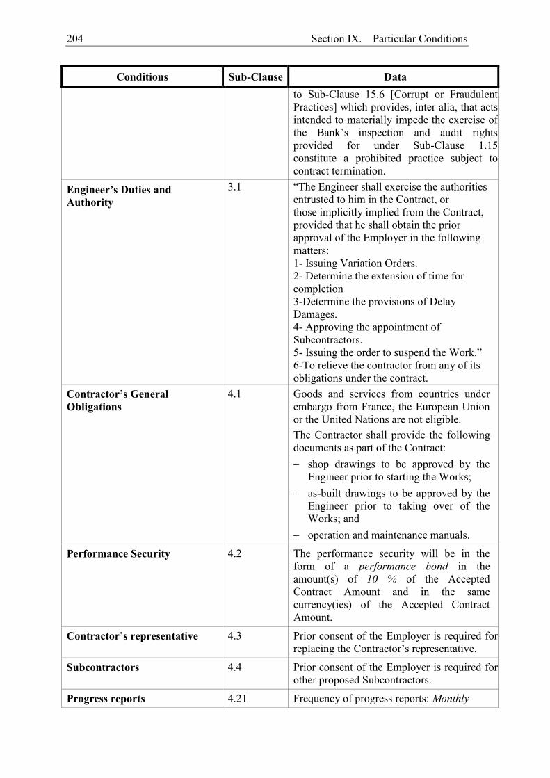
204 Section IX. Particular Conditions
Conditions Sub-Clause Data to Sub-Clause 15.6 [Corrupt or Fraudulent Practices] which provides, inter alia, that acts intended to materially impede the exercise of the Bank’s inspection and audit rights provided for under Sub-Clause 1.15 constitute a prohibited practice subject to contract termination.
Engineer’s Duties and Authority
3.1 “The Engineer shall exercise the authorities entrusted to him in the Contract, or those implicitly implied from the Contract, provided that he shall obtain the prior approval of the Employer in the following matters: 1- Issuing Variation Orders. 2- Determine the extension of time for completion 3-Determine the provisions of Delay Damages. 4- Approving the appointment of Subcontractors. 5- Issuing the order to suspend the Work.” 6-To relieve the contractor from any of its obligations under the contract.
Contractor’s General Obligations
4.1 Goods and services from countries under embargo from France, the European Union or the United Nations are not eligible. The Contractor shall provide the following documents as part of the Contract: shop drawings to be approved by the
Engineer prior to starting the Works; as-built drawings to be approved by the
Engineer prior to taking over of the Works; and
operation and maintenance manuals.
Performance Security 4.2 The performance security will be in the form of a performance bond in the amount(s) of 10 % of the Accepted Contract Amount and in the same currency(ies) of the Accepted Contract Amount.
Contractor’s representative 4.3 Prior consent of the Employer is required for replacing the Contractor’s representative.
Subcontractors 4.4 Prior consent of the Employer is required for other proposed Subcontractors.
Progress reports 4.21 Frequency of progress reports: Monthly
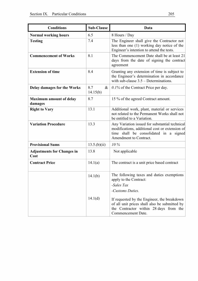
Section IX. Particular Conditions 205
Conditions Sub-Clause Data
Normal working hours 6.5 8 Hours / Day Testing 7.4 The Engineer shall give the Contractor not
less than one (1) working day notice of the Engineer’s intention to attend the tests.
Commencement of Works 8.1 The Commencement Date shall be at least 21 days from the date of signing the contract agreement
Extension of time 8.4 Granting any extension of time is subject to the Engineer’s determination in accordance with sub-clause 3.5 – Determinations.
Delay damages for the Works 8.7 & 14.15(b)
0.1% of the Contract Price per day.
Maximum amount of delay damages
8.7 15 % of the agreed Contract amount.
Right to Vary 13.1 Additional work, plant, material or services not related to the Permanent Works shall not be entitled to a Variation.
Variation Procedure 13.3 Any Variation issued for substantial technical modifications, additional cost or extension of time shall be consolidated in a signed Amendment to Contract.
Provisional Sums 13.5.(b)(ii) 10 %
Adjustments for Changes in Cost
13.8 Not applicable
Contract Price 14.1(a) The contract is a unit price based contract
14.1(b) 14.1(d)
The following taxes and duties exemptions apply to the Contract: -Sales Tax -Customs Duties.
If requested by the Engineer, the breakdown of all unit prices shall also be submitted by the Contractor within 28 days from the Commencement Date.
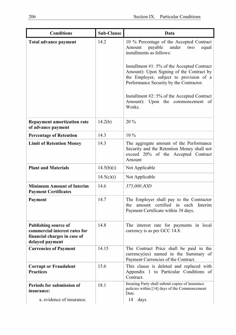
206 Section IX. Particular Conditions
Conditions Sub-Clause Data
Total advance payment 14.2 10 % Percentage of the Accepted Contract Amount payable under two equal installments as follows: Installment #1: 5% of the Accepted Contract Amount): Upon Signing of the Contract by the Employer, subject to provision of a Performance Security by the Contractor. Installment #2: 5% of the Accepted Contract Amount): Upon the commencement of Works.
Repayment amortization rate of advance payment
14.2(b) 20 %
Percentage of Retention 14.3 10 %
Limit of Retention Money 14.3 The aggregate amount of the Performance Security and the Retention Money shall not exceed 20% of the Accepted Contract Amount
Plant and Materials 14.5(b)(i) Not Applicable
14.5(c)(i) Not Applicable
Minimum Amount of Interim Payment Certificates
14.6 375,000 JOD
Payment 14.7 The Employer shall pay to the Contractor the amount certified in each Interim Payment Certificate within 56 days.
Publishing source of commercial interest rates for financial charges in case of delayed payment
14.8 The interest rate for payments in local currency is as per GCC 14.8.
Currencies of Payment 14.15 The Contract Price shall be paid in the currency(ies) named in the Summary of Payment Currencies of the Contract.
Corrupt or Fraudulent Practices
15.6 This clause is deleted and replaced with Appendix 1 to Particular Conditions of Contract.
Periods for submission of insurance:
18.1 Insuring Party shall submit copies of insurance policies within [14] days of the Commencement Date.
a. evidence of insurance. 14 days
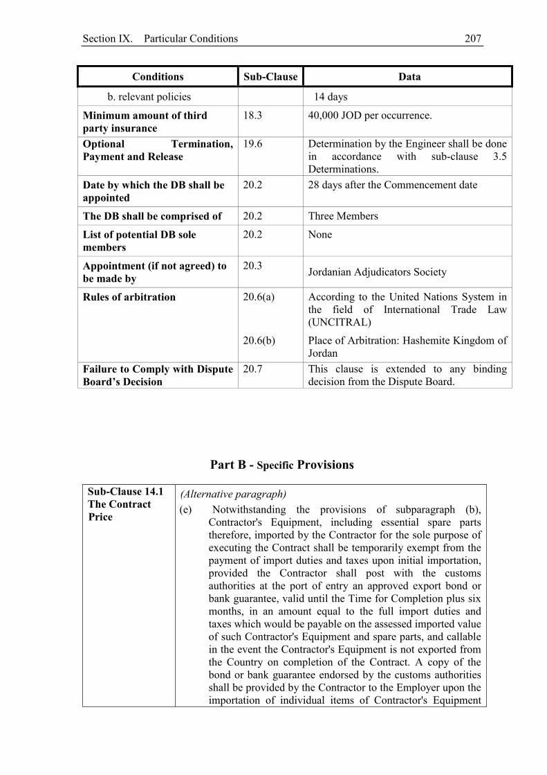
Section IX. Particular Conditions 207
Conditions Sub-Clause Data
b. relevant policies 14 days
Minimum amount of third party insurance
18.3 40,000 JOD per occurrence.
Optional Termination, Payment and Release
19.6 Determination by the Engineer shall be done in accordance with sub-clause 3.5 Determinations.
Date by which the DB shall be appointed
20.2 28 days after the Commencement date
The DB shall be comprised of 20.2 Three Members
List of potential DB sole members
20.2 None
Appointment (if not agreed) to be made by
20.3 Jordanian Adjudicators Society
Rules of arbitration 20.6(a)
According to the United Nations System in the field of International Trade Law (UNCITRAL)
20.6(b) Place of Arbitration: Hashemite Kingdom of Jordan
Failure to Comply with Dispute Board’s Decision
20.7 This clause is extended to any binding decision from the Dispute Board.
Part B - Specific Provisions
Sub-Clause 14.1 The Contract Price
(Alternative paragraph) (e) Notwithstanding the provisions of subparagraph (b),
Contractor's Equipment, including essential spare parts therefore, imported by the Contractor for the sole purpose of executing the Contract shall be temporarily exempt from the payment of import duties and taxes upon initial importation, provided the Contractor shall post with the customs authorities at the port of entry an approved export bond or bank guarantee, valid until the Time for Completion plus six months, in an amount equal to the full import duties and taxes which would be payable on the assessed imported value of such Contractor's Equipment and spare parts, and callable in the event the Contractor's Equipment is not exported from the Country on completion of the Contract. A copy of the bond or bank guarantee endorsed by the customs authorities shall be provided by the Contractor to the Employer upon the importation of individual items of Contractor's Equipment
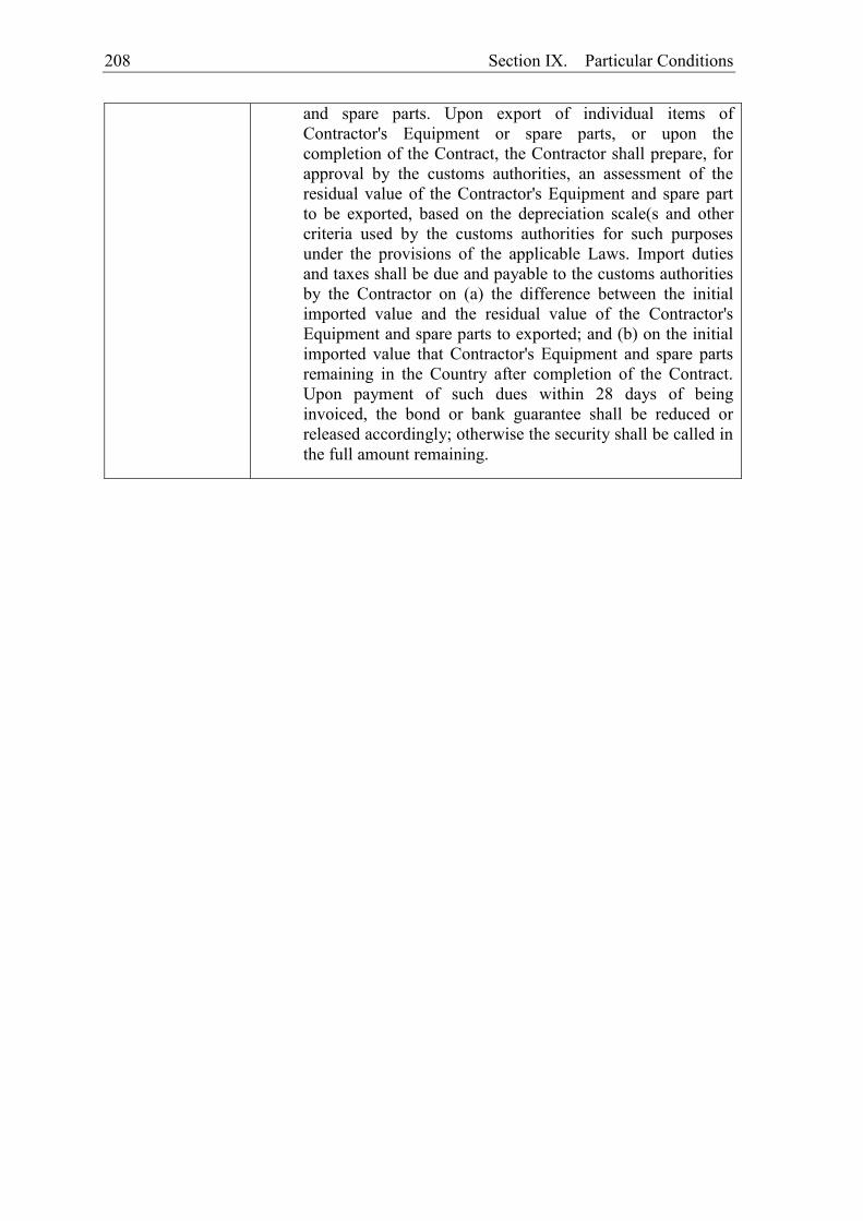
208 Section IX. Particular Conditions
and spare parts. Upon export of individual items of Contractor's Equipment or spare parts, or upon the completion of the Contract, the Contractor shall prepare, for approval by the customs authorities, an assessment of the residual value of the Contractor's Equipment and spare part to be exported, based on the depreciation scale(s and other criteria used by the customs authorities for such purposes under the provisions of the applicable Laws. Import duties and taxes shall be due and payable to the customs authorities by the Contractor on (a) the difference between the initial imported value and the residual value of the Contractor's Equipment and spare parts to exported; and (b) on the initial imported value that Contractor's Equipment and spare parts remaining in the Country after completion of the Contract. Upon payment of such dues within 28 days of being invoiced, the bond or bank guarantee shall be reduced or released accordingly; otherwise the security shall be called in the full amount remaining.

Section IX. Particular Conditions 209
Appendix 1 to Particular Conditions of Contract
Corrupt and Fraudulent Practices Policy
The Employer, the Implementing Agency and the contractors, suppliers or consultants must observe the highest standard of ethics during contract procurement and performance. By signing the Statement of Integrity (form available as Appendix to Letter of Bid) the contractor, supplier or consultant declares that (i) “it did not engage in any practice likely to influence the contract award process to the Employer's detriment, and that it did not and will not get involved in any anti-competitive practice”, and that (ii) “the negotiation, the procurement and the performance of the contract did not and shall not give rise to any act of corruption or fraud”. Moreover, the Agency requires including in the Bidding Documents and Agency-financed contracts a provision requiring that bidders and contractors, suppliers and consultants will permit the Agency to inspect their accounts and records relating to the procurement and performance of the Agency-financed contract, and to have them audited by auditors appointed by the Agency. The Agency reserves the right to take any action it deems appropriate to check that these ethics rules are observed and reserves, in particular, the rights to: a) reject a proposal for a contract award if it is established that during the selection
process the bidder that is recommended for the award has been convicted of corruption, directly or by means of an agent, or has engaged in fraud or anti-competitive practices in view of being awarded the Contract;
b) declare misprocurement when it is established that, at any time, the Employer, the
contractor, the supplier, the consultant or its representatives have engaged in acts of corruption, fraud or anti-competitive practices during the contract procurement or performance without the Employer having taken appropriate action in due time satisfactory to the Agency to remedy the situation, including by failing to inform the Agency at the time they knew of such practices.
The Agency defines, for the purposes of this provision, the terms set forth below as follows:
(a) Corruption of a public officer means:
- the act of promising, offering or giving to a public officer, directly or indirectly, an undue advantage of any kind for himself or for another person or entity, for such public officer to act or refrain from acting in his official capacity; or
- the act by which a public officer solicits or accepts, directly or indirectly, an undue advantage of any kind for himself or for another person or entity, for
210 Section IX. Particular Conditions
such public officer to act or refrain from acting in his official capacity.
(b) A "public officer" shall be construed as meaning
- any person who holds a legislative, executive, administrative or judicial mandate (within the State of the Employer) regardless of whether that person was nominated or elected, regardless of the permanent or temporary, paid or unpaid nature of the position and regardless of the hierarchical level the person occupies;
- any other person who performs a public function, including for a State institution or a State-owned company, or who provides a public service;
- any other person defined as a public officer by the national laws of the Employer.
(c) Corruption of a private person means:
- the act of promising, offering or giving to any person other than a public officer, directly or indirectly, an undue advantage of any kind for himself or for another person or entity, for such person to perform or refrain from performing any act in breach of its legal, contractual or professional obligations; or
- the act by which any person other than a public officer solicits or accepts, directly or indirectly, an undue advantage of any kind for himself or for another person or entity, for such person to perform or refrain from performing any act in breach of its legal, contractual or professional obligations.
(d) Fraud means any dishonest conduct (act or omission), whether or not it constitutes a criminal offence, deliberately intended to deceive others, to intentionally conceal items, to violate or vitiate consent, to circumvent legal or regulatory requirements and/or to violate internal rules in order to obtain illegitimate profit.
(e) Anti-competitive practices means:
- any concerted or implied practices which have as their object or effect the prevention, restriction or distortion of competition within a marketplace, especially where they (i) limit access to the marketplace or free exercise of competition by other undertakings, (ii) prevent free, competition-driven price determination by artificially causing price increases or decreases, (iii) restrict or control production, markets, investments or technical progress; or (iv) divide up market shares or sources of supply.
- any abuse by one undertaking or a group of undertakings which hold a dominant position on an internal market or on a substantial part of it.
- any practice whereby prices are quoted or set unreasonably low, the object of which is to eliminate an undertaking or any of its products from a market or to prevent it from entering the market.
Section X. Contract Forms 211
Section X. Contract Forms
Table of Forms
Notification of Award ......................................................................................................... 212
Contract Agreement ........................................................................................................... 213
Performance Security ......................................................................................................... 214
Advance Payment Security ................................................................................................ 217
Retention Money Security .................................................................................................. 219
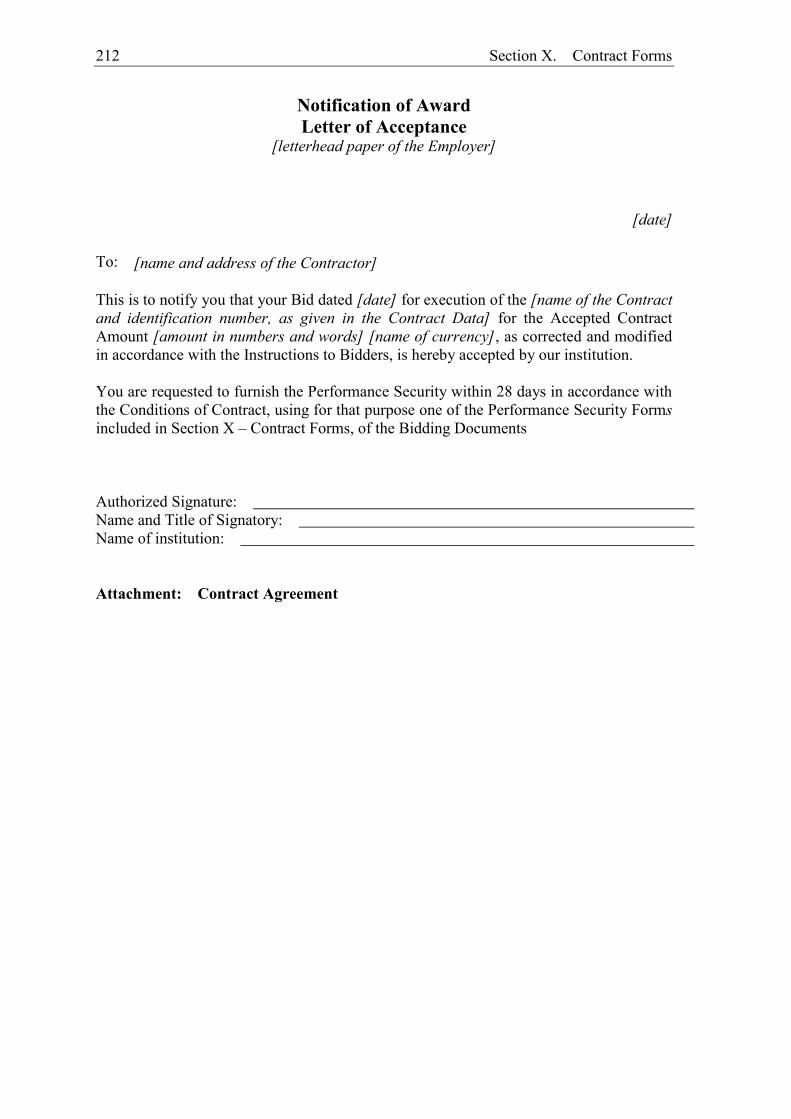
212 Section X. Contract Forms
Notification of Award
Letter of Acceptance [letterhead paper of the Employer]
[date] To: [name and address of the Contractor] This is to notify you that your Bid dated [date] for execution of the [name of the Contract and identification number, as given in the Contract Data] for the Accepted Contract Amount [amount in numbers and words] [name of currency], as corrected and modified in accordance with the Instructions to Bidders, is hereby accepted by our institution. You are requested to furnish the Performance Security within 28 days in accordance with the Conditions of Contract, using for that purpose one of the Performance Security Forms included in Section X – Contract Forms, of the Bidding Documents Authorized Signature: Name and Title of Signatory: Name of institution: Attachment: Contract Agreement
Section X. Contract Forms 213
Contract Agreement
THIS AGREEMENT made the ________ day of ________________________, _____, between ______________________________________of __________________________ (hereinafter “the Employer”), of the one part, and ______________________ of _____________________ (hereinafter “the Contractor”), of the other part:
WHEREAS the Employer desires that the Works known as _______________________________ should be executed by the Contractor, and has accepted a Bid by the Contractor for the execution and completion of these Works and the remedying of any defects therein, in the sum of [insert Contract Price or Ceiling in words and figures, expressed in the Contract currency(ies)] (hereafter called “the Contract Price”).
The Employer and the Contractor agree as follows:
1. In this Agreement words and expressions shall have the same meanings as are respectively assigned to them in the Contract documents referred to.
2. The following documents shall be deemed to form and be read and construed as part of this Agreement. This Agreement shall prevail over all other Contract documents.
(i) the Letter of Acceptance (ii) the Letter of Bid and Bid Data Sheet (including the signed Statement of
Integrity) (iii) the addenda Nos ________(if any) (iv) the Particular Conditions (v) the General Conditions;
(vi) the Technical Specifications (vii) the Drawings; and
(viii) the completed Schedules and any other documents forming part of the contract,
3. In consideration of the payments to be made by the Employer to the Contractor as specified in this Agreement, the Contractor hereby covenants with the Employer to execute the Works and to remedy defects therein in conformity in all respects with the provisions of the Contract.
4. The Employer hereby covenants to pay the Contractor in consideration of the execution and completion of the Works and the remedying of defects therein, the Contract Price or such other sum as may become payable under the provisions of the Contract at the times and in the manner prescribed by the Contract.
IN WITNESS whereof the parties hereto have caused this Agreement to be executed in accordance with the laws of _____________________________ on the day, month and year specified above.
Signed by ________________________________________________ (for the Employer)
Signed by ________________________________________________(for the Contractor)
214 Section X. Contract Forms
Performance Security
Option 1: (Demand Guarantee) Beneficiary: ___________________ Date: ________________ PERFORMANCE GUARANTEE No.: _________________ Guarantor: _____________________________________ We have been informed that ________________ (hereinafter called "the Applicant") has entered into Contract No. _____________ dated ____________ with the Beneficiary, for the execution of _____________________ (hereinafter called "the Contract"). Furthermore, we understand that, according to the conditions of the Contract, a performance guarantee is required. At the request of the Applicant, we as Guarantor,hereby irrevocably undertake to pay the Beneficiary any sum or sums not exceeding in total an amount of ___________ ( ),1 such sum being payable in the types and proportions of currencies in which the Contract Price is payable, upon receipt by us of the Beneficiary’s first demand supported by the Beneficiary’s statement, whether in the demand itself or in a separate signed document accompanying or identifying the demand, stating that the Applicant is in breach of its obligation(s) under the Contract, without the Beneficiary needing to prove or to show grounds for your demand or the sum specified therein. This guarantee shall expire, no later than the …. Day of ……, 2… 2, and any demand for payment under it must be received by us at this office indicated above on or before that date. This guarantee is subject to the Uniform Rules for Demand Guarantees (URDG) 2010 Revision, ICC Publication No. 758, except that the supporting statement under Article 15(a) is hereby excluded.
_____________________ [signature(s)]
Note: All italicized text (including footnotes) is for use in preparing this form and shall be deleted from the final product.
1 The Guarantor shall insert an amount representing the percentage of the Accepted Contract Amount
specified in the Letter of Acceptance, less provisional sums, if any, and denominated either in the currency(cies) of the Contract or a freely convertible currency acceptable to the Beneficiary.
2 Insert the date twenty-eight days after the expected completion date as described in GC Clause 11.9. The Employer should note that in the event of an extension of this date for completion of the Contract, the Employer would need to request an extension of this guarantee from the Guarantor. Such request must be in writing and must be made prior to the expiration date established in the guarantee. In preparing this guarantee, the Employer might consider adding the following text to the form, at the end of the penultimate paragraph: “The Guarantor agrees to a one-time extension of this guarantee for a period not to exceed [six months][one year], in response to the Beneficiary’s written request for such extension, such request to be presented to the Guarantor before the expiry of the guarantee.”
Section X. Contract Forms 215
Option 2: Performance Bond By this Bond____________________ as Principal (hereinafter called “the Contractor”) and______________________________________________________________] as Surety (hereinafter called “the Surety”), are held and firmly bound unto_____________________] as Obligee (hereinafter called “the Employer”) in the amount of __________________, for the payment of which sum well and truly to be made in the types and proportions of currencies in which the Contract Price is payable, the Contractor and the Surety bind themselves, their heirs, executors, administrators, successors and assigns, jointly and severally, firmly by these presents. WHEREAS the Contractor has entered into a written Agreement with the Employer dated the day of , 20 , for ___________________ in accordance with the documents, plans, specifications, and amendments thereto, which to the extent herein provided for, are by reference made part hereof and are hereinafter referred to as the Contract. NOW, THEREFORE, the Condition of this Obligation is such that, if the Contractor shall promptly and faithfully perform the said Contract (including any amendments thereto), then this obligation shall be null and void; otherwise, it shall remain in full force and effect. Whenever the Contractor shall be, and declared by the Employer to be, in default under the Contract, the Employer having performed the Employer’s obligations thereunder, the Surety may promptly remedy the default, or shall promptly:
(1) complete the Contract in accordance with its terms and conditions; or (2) obtain a Bid or bids from qualified Bidders for submission to the Employer for
completing the Contract in accordance with its terms and conditions, and upon determination by the Employer and the Surety of the lowest responsive Bidder, arrange for a Contract between such Bidder and Employer and make available as work progresses (even though there should be a default or a succession of defaults under the Contract or Contracts of completion arranged under this paragraph) sufficient funds to pay the cost of completion less the Balance of the Contract Price; but not exceeding, including other costs and damages for which the Surety may be liable hereunder, the amount set forth in the first paragraph hereof. The term “Balance of the Contract Price,” as used in this paragraph, shall mean the total amount payable by Employer to Contractor under the Contract, less the amount properly paid by Employer to Contractor; or
(3) pay the Employer the amount required by Employer to complete the Contract
in accordance with its terms and conditions up to a total not exceeding the amount of this Bond.
The Surety shall not be liable for a greater sum than the specified penalty of this Bond. Any suit under this Bond must be instituted before the expiration of one year from the date of the issuing of the Taking-Over Certificate.
216 Section X. Contract Forms
No right of action shall accrue on this Bond to or for the use of any person or corporation other than the Employer named herein or the heirs, executors, administrators, successors, and assigns of the Employer. In testimony whereof, the Contractor has hereunto set his hand and affixed his seal, and the Surety has caused these presents to be sealed with his corporate seal duly attested by the signature of his legal representative, this day of 20 . SIGNED ON on behalf of By in the capacity of In the presence of SIGNED ON on behalf of By in the capacity of In the presence of
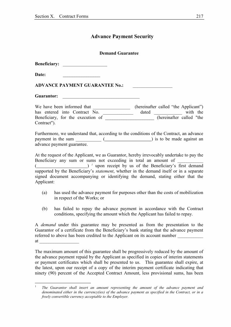
Section X. Contract Forms 217
Advance Payment Security
Demand Guarantee
Beneficiary: ___________________ Date: ________________ ADVANCE PAYMENT GUARANTEE No.: _________________ Guarantor: _________________________________ We have been informed that ________________ (hereinafter called “the Applicant”) has entered into Contract No. _____________ dated ____________ with the Beneficiary, for the execution of _____________________ (hereinafter called "the Contract"). Furthermore, we understand that, according to the conditions of the Contract, an advance payment in the sum ___________ ( ) is to be made against an advance payment guarantee. At the request of the Applicant, we as Guarantor, hereby irrevocably undertake to pay the Beneficiary any sum or sums not exceeding in total an amount of ___________ ( ) 1 upon receipt by us of the Beneficiary’s first demand supported by the Beneficiary’s statement, whether in the demand itself or in a separate signed document accompanying or identifying the demand, stating either that the Applicant:
(a) has used the advance payment for purposes other than the costs of mobilization in respect of the Works; or
(b) has failed to repay the advance payment in accordance with the Contract
conditions, specifying the amount which the Applicant has failed to repay. A demand under this guarantee may be presented as from the presentation to the Guarantor of a certificate from the Beneficiary’s bank stating that the advance payment referred to above has been credited to the Applicant on its account number ___________ at _________________ The maximum amount of this guarantee shall be progressively reduced by the amount of the advance payment repaid by the Applicant as specified in copies of interim statements or payment certificates which shall be presented to us. This guarantee shall expire, at the latest, upon our receipt of a copy of the interim payment certificate indicating that ninety (90) percent of the Accepted Contract Amount, less provisional sums, has been
1 The Guarantor shall insert an amount representing the amount of the advance payment and
denominated either in the currency(ies) of the advance payment as specified in the Contract, or in a freely convertible currency acceptable to the Employer.
218 Section X. Contract Forms
certified for payment, or on the ___ day of _____, 2___,2 whichever is earlier. Consequently, any demand for payment under this guarantee must be received by us at this office on or before that date. This guarantee is subject to the Uniform Rules for Demand Guarantees (URDG) 2010 Revision, ICC Publication No. 758, except that the supporting statement under Article 15(a) is hereby excluded. ____________________ [signature(s)] Note: All italicized text (including footnotes) is for use in preparing this form and shall be deleted from the final product.
2 Insert the expected expiration date of the Time for Completion. The Employer should note that in the
event of an extension of the time for completion of the Contract, the Employer would need to request an extension of this guarantee from the Guarantor. Such request must be in writing and must be made prior to the expiration date established in the guarantee. In preparing this guarantee, the Employer might consider adding the following text to the form, at the end of the penultimate paragraph: “The Guarantor agrees to a one-time extension of this guarantee for a period not to exceed [six months][one year], in response to the Beneficiary’s written request for such extension, such request to be presented to the Guarantor before the expiry of the guarantee.”

Section X. Contract Forms 219
Retention Money Security
Demand Guarantee
________________________________ [Guarantor letterhead or SWIFT identifier code] Beneficiary: ___________________ [Insert name and Address of Employer] Date: ________________[Insert date of issue] RETENTION MONEY GUARANTEE No.: [Insert guarantee reference number] Guarantor: [Insert name and address of place of issue, unless indicated in the letterhead] We have been informed that ________________ [insert name of Contractor, which in the case of a joint venture shall be the name of the joint venture] (hereinafter called "the Applicant") has entered into Contract No. _____________ [insert reference number of the contract] dated ____________ with the Beneficiary, for the execution of _____________________ [insert name of contract and brief description of Works] (hereinafter called "the Contract"). Furthermore, we understand that, according to the conditions of the Contract, the Beneficiary retains moneys up to the limit set forth in the Contract (“the Retention Money”), and that when the Taking-Over Certificate has been issued under the Contract and the first half of the Retention Money has been certified for payment, payment of [insert the second half of the Retention Money or if the amount guaranteed under the Performance Guarantee when the Taking-Over Certificate is issued is less than half of the Retention Money, the difference between half of the Retention Money and the amount guaranteed under the Performance Security] is to be made against a Retention Money guarantee. At the request of the Applicant, we, as Guarantor, hereby irrevocably undertake to pay the Beneficiary any sum or sums not exceeding in total an amount of ___________ [insert amount in figures] ( ) [amount in words]1 upon receipt by us of the Beneficiary’s first demand supported by the Beneficiary’s statement, whether in the demand itself or in a separate signed document accompanying or identifying the demand, stating that the Applicant is in breach of its obligation(s) under the Contract, without your needing to prove or show grounds for your demand or the sum specified therein. A demand under this guarantee may be presented as from the presentation to the Guarantor of a certificate from the Beneficiary’s bank stating that the second half of the Retention Money as referred to above has been credited to the Applicant on its account
1 The Guarantor shall insert an amount representing the amount of the second half of the Retention
Money or or if the amount guaranteed under the Performance Guarantee when the Taking-Over Certificate is issued is less than half of the Retention Money, the difference between half of the Retention Money and the amount guaranteed under the Performance Security and denominated either in the currency(ies) of the second half of the Retention Money as specified in the Contract, or in a freely convertible currency acceptable to the Beneficiary.
220 Section X. Contract Forms
number ___________ at _________________ [insert name and address of Applicant’s bank]. This guarantee shall expire no later than the …. day of ……, 2… 2, and any demand for payment under it must be received by us at the office indicated above on or before that date. This guarantee is subject to the Uniform Rules for Demand Guarantees (URDG) 2010 Revision, ICC Publication No. 758, except that the supporting statement under Article 15(a) is hereby excluded.
2 Insert the same expiry date as set forth in the performance security, representing the date twenty-eight
days after the completion date described in GC Clause 11.9. The Employer should note that in the event of an extension of this date for completion of the Contract, the Employer would need to request an extension of this guarantee from the Guarantor. Such request must be in writing and must be made prior to the expiration date established in the guarantee. In preparing this guarantee, the Employer might consider adding the following text to the form, at the end of the penultimate paragraph: “The Guarantor agrees to a one-time extension of this guarantee for a period not to exceed [six months][one year], in response to the Beneficiary’s written request for such extension, such request to be presented to the Guarantor before the expiry of the guarantee.”
Vol. II: Technical Specifications

i
TABLE OF CONTENTS
DIVISION 01: GENERAL REQUIREMENTS ................................................................................................. 1
SECTION 01010 - SUMMARY OF WORK ....................................................................................................... 1
PART 1 -- GENERAL ........................................................................................................................................ 1 1.1 GENERAL ............................................................................................................................................ 1 1.2 LOCATION ........................................................................................................................................... 2 1.3 CLIMATE ............................................................................................................................................. 2 1.4 REQUIREMENTS ................................................................................................................................ 2 1.5 SCOPE OF WORK ................................................................................................................................ 2 1.6 WORK SEQUENCE ............................................................................................................................. 2 1.7 CONTRACTOR USE OF SITES .......................................................................................................... 2 1.8 OUTAGE PLAN AND REQUESTS ..................................................................................................... 3 1.9 EMPLOYER USE OF SITES ................................................................................................................ 3 1.10 PROJECT MEETINGS ......................................................................................................................... 3 1.11 CONTRACT DRAWINGS ................................................................................................................... 5
SECTION 01020 – STANDARD SPECIFICATIONS ....................................................................................... 6
PART 1 -- GENERAL ........................................................................................................................................ 6 1.1 GENERAL ............................................................................................................................................ 6 1.2 ABBREVIATIONS ............................................................................................................................... 6
SECTION 01025 –MEASUREMENT AND PAYMENT .................................................................................. 7
PART 1 -- GENERAL ........................................................................................................................................ 7 1.1 DESCRIPTION ..................................................................................................................................... 7 1.2 CONTRACT METHOD ........................................................................................................................ 7
SECTION 01090 – REFERENCE STANDARDS .............................................................................................. 8
PART 1 -- GENERAL ........................................................................................................................................ 8 1.1 GENERAL ............................................................................................................................................ 8 1.2 REFERENCE SPECIFICATIONS, CODES, AND STANDARDS ...................................................... 8
SECTION 01300 - CONTRACTOR SUBMITTALS ......................................................................................... 9
PART 1 -- GENERAL ........................................................................................................................................ 9 1.1 GENERAL ............................................................................................................................................ 9 1.2 PRECONSTRUCTION CONFERENCE SUBMITTALS .................................................................... 9 1.3 SHOP DRAWINGS ............................................................................................................................... 9 1.4 CONTRACTOR'S SCHEDULE .......................................................................................................... 11 1.5 SAMPLES ........................................................................................................................................... 11 1.6 RECORD DRAWINGS ....................................................................................................................... 12
SECTION 01301 - SCHEDULE OF VALUES ................................................................................................. 13
PART 1 -- GENERAL ...................................................................................................................................... 13 1.1 GENERAL .......................................................................................................................................... 13 1.2 PRELIMINARY SCHEDULE OF VALUES ...................................................................................... 13 1.3 DETAILED SCHEDULE OF VALUES ............................................................................................. 13 1.4 CROSS REFERENCE LISTING ......................................................................................................... 14 1.5 CHANGES TO SCHEDULE OF VALUES ........................................................................................ 14 1.6 TIMELINESS OF SUBMITTALS ...................................................................................................... 15
SECTION 01311 - CPM CONSTRUCTION SCHEDULE ............................................................................. 16
PART 1 -- GENERAL ...................................................................................................................................... 16
ii
1.1 GENERAL .......................................................................................................................................... 16 1.2 QUALIFICATIONS ............................................................................................................................ 16 1.3 INITIAL SCHEDULE SUBMITTALS ............................................................................................... 16 1.4 CPM SCHEDULE SUBMITTALS ..................................................................................................... 17 1.5 CHANGE ORDERS ............................................................................................................................ 19 1.6 CPM STANDARDS ............................................................................................................................ 19 1.7 SCHEDULE REPORT FORMAT ....................................................................................................... 20 1.8 PROJECT STATUS REPORTING ..................................................................................................... 21
SECTION 01313 - CONSTRUCTION AND SCHEDULE CONSTRAINTS ................................................ 23
PART 1 -- GENERAL ...................................................................................................................................... 23 1.1 GENERAL .......................................................................................................................................... 23 1.2 PERMITS ............................................................................................................................................ 23 1.3 SCHEDULE CONSTRAINTS ............................................................................................................ 23
SECTION 01400 - QUALITY CONTROL ....................................................................................................... 24
PART 1 -- GENERAL ...................................................................................................................................... 24 1.1 DEFINITION ...................................................................................................................................... 24 1.2 INSPECTION AT PLACE OF MANUFACTURE ............................................................................. 24 1.3 SAMPLING AND TESTING .............................................................................................................. 24 1.4 INSPECTION AND TESTING SERVICE .......................................................................................... 24 PART 2 -- EXECUTION .................................................................................................................................. 25 2.1 INSTALLATION ................................................................................................................................ 25
SECTION 01505 – MOBILIZATION ............................................................................................................... 26
PART 1 -- GENERAL ...................................................................................................................................... 26 1.1 GENERAL .......................................................................................................................................... 26
SECTION 01510 - TEMPORARY UTILITIES ............................................................................................... 27
PART 1 -- GENERAL ...................................................................................................................................... 27 1.1 GENERAL REQUIREMENTS ........................................................................................................... 27 1.2 JOB CONDITIONS ............................................................................................................................. 27 PART 2 -- PRODUCTS .................................................................................................................................... 27 2.1 MATERIALS ...................................................................................................................................... 27 PART 3 -- EXECUTION .................................................................................................................................. 27 3.1 INSTALLATION OF TEMPORARY UTILITY SERVICES ............................................................. 27 3.2 INSTALLATION OF POWER DISTRIBUTION SYSTEM .............................................................. 28 3.3 INSTALLATION OF LIGHTING ...................................................................................................... 28 3.4 WATER SUPPLY ............................................................................................................................... 28 3.5 INSTALLATION OF SANITARY FACILITIES ............................................................................... 29 3.6 INSTALLATION OF FIRE PROTECTION ....................................................................................... 29 3.7 INSTALLATION OF COMMUNICATIONS ..................................................................................... 29 3.8 OPERATIONS AND TERMINATIONS ............................................................................................ 30
SECTION 01520 - SECURITY .......................................................................................................................... 31
PART 1 -- GENERAL ...................................................................................................................................... 31 1.1 SECURITY PROGRAM ..................................................................................................................... 31 1.2 ENTRY CONTROL ............................................................................................................................ 31 1.3 PERSONNEL IDENTIFICATION ..................................................................................................... 31 1.4 SECURITY SERVICE ........................................................................................................................ 31 1.5 RESTRICTIONS ................................................................................................................................. 31
SECTION 01530 - PROTECTION OF EXISTING FACILITIES ................................................................. 32
iii
PART 1 -- GENERAL ...................................................................................................................................... 32 1.1 GENERAL .......................................................................................................................................... 32 1.2 RIGHTS-OF-WAY ............................................................................................................................. 32 1.3 PROTECTION OF STREET OR ROADWAY MARKERS ............................................................... 32 1.4 RESTORATION OF PAVEMENT ..................................................................................................... 32 1.5 EXISTING UTILITIES AND IMPROVEMENTS .............................................................................. 33 1.6 TREES OR SHRUBS WITHIN STREET RIGHTS-OF-WAY AND PROJECT LIMITS .................. 34 1.7 LAWN AREAS ................................................................................................................................... 35 1.8 NOTIFICATION BY THE CONTRACTOR ...................................................................................... 35
SECTION 01532 - SITE CONDITIONS SURVEYS ....................................................................................... 36
PART 1 -- GENERAL ...................................................................................................................................... 36 1.1 THE REQUIREMENT ........................................................................................................................ 36 1.2 CONTRACTOR SUBMITTALS ........................................................................................................ 36 PART 2 -- EXECUTION .................................................................................................................................. 36 2.1 PHOTOGRAPHS ................................................................................................................................ 36 2.2 TOPOGRAPHIC MAPPING .............................................................................................................. 36
SECTION 01550 - SITE ACCESS AND STORAGE ....................................................................................... 38
PART 1 -- GENERAL ...................................................................................................................................... 38 1.1 HIGHWAY LIMITATIONS ............................................................................................................... 38 1.2 TEMPORARY CROSSINGS .............................................................................................................. 38 1.3 CONTRACTOR'S WORK AND STORAGE AREA .......................................................................... 39 1.4 PARKING ........................................................................................................................................... 40
SECTION 01560 - TEMPORARY ENVIRONMENTAL CONTROLS ........................................................ 41
PART 1 -- GENERAL ...................................................................................................................................... 41 1.1 EXPLOSIVES AND BLASTING ....................................................................................................... 41 1.2 DUST ABATEMENT ......................................................................................................................... 41 1.3 RUBBISH CONTROL ........................................................................................................................ 41 1.4 SANITATION ..................................................................................................................................... 41 1.5 CULTURAL RESOURCES ................................................................................................................ 41
SECTION 01580 - PROJECT SIGNS ............................................................................................................... 43
PART 1 -- GENERAL ...................................................................................................................................... 43 1.1 THE REQUIREMENT ........................................................................................................................ 43 PART 2 -- PRODUCTS .................................................................................................................................... 43 2.1 SIGN CONSTRUCTION .................................................................................................................... 43 2.2 COLORS ............................................................................................................................................. 43 2.3 SIGN CONTENT ................................................................................................................................ 43 PART 3 -- EXECUTION .................................................................................................................................. 43 3.1 SIGN LOCATION ............................................................................................................................... 43 3.2 REMOVAL ......................................................................................................................................... 43
SECTION 01590 - FIELD OFFICE, EQUIPMENT, ENGINEER’S TRANSPORTATION AND SERVICES........................................................................................................................................................... 44
PART 1 -- GENERAL ...................................................................................................................................... 44 1.1 GENERAL .......................................................................................................................................... 44 1.2 FIELD OFFICE SCHEDULE .............................................................................................................. 44 PART 2 -- PRODUCTS .................................................................................................................................... 44 2.1 OFFICE FACILITIES ......................................................................................................................... 44 2.2 FIELD OFFICE FURNISHINGS ........................................................................................................ 44 2.3 FIELD OFFICE SERVICES ................................................................................................................ 45
iv
2.4 TELEPHONE SERVICE ..................................................................................................................... 46 2.5 OFFICE COPY MACHINE................................................................................................................. 46 2.6 COMPUTER AND PRINTER ............................................................................................................. 46 2.7 FACSIMILE MACHINE ..................................................................................................................... 47 2.8 DIGITAL CAMERA ........................................................................................................................... 47 2.9 EMPLOYER’S TRANSPORT ............................................................................................................ 47
SECTION 01600 - PRODUCTS, MATERIALS, EQUIPMENT AND SUBSTITUTIONS ......................... 49
PART 1 -- GENERAL ...................................................................................................................................... 49 1.1 DEFINITIONS .................................................................................................................................... 49 1.2 QUALITY ASSURANCE ................................................................................................................... 49 1.3 PRODUCT DELIVERY AND STORAGE ......................................................................................... 49 1.4 TRANSPORTATION AND HANDLING .......................................................................................... 49 1.5 STORAGE AND PROTECTION ........................................................................................................ 50 1.6 MAINTENANCE OF PRODUCTS IN STORAGE ............................................................................ 50 1.7 PROPOSED SUBSTITUTIONS OR "OR-EQUAL" ITEM ................................................................ 50
SECTION 01640 - DEMOLITION AND RECONSTRUCTION ................................................................... 53
PART 1 -- GENERAL ...................................................................................................................................... 53 1.1 THE REQUIREMENT ........................................................................................................................ 53 1.2 COORDINATION .............................................................................................................................. 53 1.3 CONTRACTOR SUBMITTALS ........................................................................................................ 53 1.4 DEMOLITION .................................................................................................................................... 54 1.5 REHABILITATION ............................................................................................................................ 54 1.6 DISPOSAL .......................................................................................................................................... 54 PART 2 -- EXECUTION .................................................................................................................................. 54 2.1 GENERAL .......................................................................................................................................... 54 2.2 PROTECTION OF EXISTING FACILITIES ..................................................................................... 54 2.3 DEMOLITION, SALVAGE, AND RELOCATION ........................................................................... 55 2.4 ABANDONMENT .............................................................................................................................. 56 2.5 REHABILITATION ............................................................................................................................ 56 2.6 DISPOSAL .......................................................................................................................................... 57 2.7 OCCUPANCY AND POLLUTION CONTROL ................................................................................ 57 2.8 CLEANING ......................................................................................................................................... 58
SECTION 01700 - PROJECT CLOSEOUT ..................................................................................................... 59
PART 1 -- GENERAL ...................................................................................................................................... 59 1.1 FINAL CLEANUP .............................................................................................................................. 59 1.2 CLOSEOUT TIMETABLE ................................................................................................................. 59 1.3 FINAL SUBMITTALS........................................................................................................................ 59 1.4 MAINTENANCE AND GUARANTEE ............................................................................................. 59 1.5 MAINTENANCE GUARANTEE ....................................................................................................... 60 1.6 EMPLOYER’S TAKING OVER ........................................................................................................ 60
DIVISION 02: SITEWORK............................................................................................................................... 61
SECTION 02010 - SITE PREPARATION ....................................................................................................... 61
PART 1 -- GENERAL ...................................................................................................................................... 61 1.1 THE REQUIREMENT ........................................................................................................................ 61 1.2 SITE INSPECTION ............................................................................................................................. 61 PART 2 -- EXECUTION .................................................................................................................................. 61 2.1 PRIMARY PLANT SITE ACCESS .................................................................................................... 61 2.2 CLEARING, GRUBBING, AND STRIPPING ................................................................................... 61
v
2.3 OVEREXCAVATION, REGRADING, AND BACKFILL UNDER FILL AREAS ........................... 62
SECTION 02140 - DEWATERING .................................................................................................................. 63
PART 1 -- GENERAL ...................................................................................................................................... 63 1.1 THE REQUIREMENT ........................................................................................................................ 63 1.2 CONTRACTOR SUBMITTALS ........................................................................................................ 63 1.3 QUALITY CONTROL ........................................................................................................................ 63 PART 2 -- PRODUCTS .................................................................................................................................... 63 2.1 EQUIPMENT ...................................................................................................................................... 63 PART 3 -- EXECUTION .................................................................................................................................. 63 3.1 GENERAL REQUIREMENTS ........................................................................................................... 63
SECTION 02200 - EARTHWORK ................................................................................................................... 65
PART 1 -- GENERAL ...................................................................................................................................... 65 1.1 THE REQUIREMENT ........................................................................................................................ 65 PART 2 -- PRODUCTS .................................................................................................................................... 65 2.1 SUITABLE FILL AND BACKFILL MATERIAL REQUIREMENTS .............................................. 65 2.2 UNSUITABLE MATERIAL ............................................................................................................... 69 2.3 USE OF FILL, BACKFILL, AND EMBANKMENT MATERIAL TYPES ....................................... 70 2.4 MATERIALS TESTING ..................................................................................................................... 71 PART 3 -- EXECUTION .................................................................................................................................. 71 3.1 EXCAVATION - GENERAL ............................................................................................................. 71 3.2 PIPELINE AND UTILITY TRENCH EXCAVATION ...................................................................... 72 3.3 OVER-EXCAVATION NOT ORDERED OR INDICATED .............................................................. 72 3.4 EXCAVATION IN LAWN AREAS ................................................................................................... 73 3.5 EXCAVATION IN VICINITY OF TREES ......................................................................................... 73 3.6 ROCK EXCAVATION ....................................................................................................................... 73 3.7 DISPOSAL OF EXCESS EXCAVATED MATERIAL ...................................................................... 73 3.8 BACKFILL - GENERAL .................................................................................................................... 73 3.9 PLACING AND SPREADING OF BACKFILL MATERIALS .......................................................... 74 3.10 COMPACTION OF FILL AND BACKFILL ...................................................................................... 74 3.11 PIPE AND UTILITY TRENCH BACKFILL ...................................................................................... 75 3.12 FILL..................................................................................................................................................... 76 3.13 FIELD TESTING ................................................................................................................................ 76
SECTION 02441 - PIPELINE CONSTRUCTION BY TRENCHLESS METHODS ................................... 78
PART 1 -- GENERAL ...................................................................................................................................... 78 1.1 GENERAL .......................................................................................................................................... 78 1.2 PIPE JACKING ................................................................................................................................... 78 1.3 CASING PIPE DETAILS .................................................................................................................... 78 1.4 SCOPE OF WORKS ............................................................................................................................ 78 1.5 CONTRACTOR’S GENERAL REQUIREMENTS ............................................................................ 80 1.6 INSTALLATION WORKS ................................................................................................................. 81
SECTION 02460 - A.C. PAVEMENT AND BASE .......................................................................................... 82
PART 1 -- GENERAL ...................................................................................................................................... 82 1.1 THE REQUIREMENT ........................................................................................................................ 82 1.2 REFERENCE SPECIFICATIONS, CODES, AND STANDARDS .................................................... 82 1.3 CONTRACTOR SUBMITTALS ........................................................................................................ 83 PART 2 -- PRODUCTS .................................................................................................................................... 84 2.1 AGGREGATE BASE COURSE ......................................................................................................... 84 2.2 TACK COAT....................................................................................................................................... 84 2.3 ASPHALT CEMENT .......................................................................................................................... 84
vi
2.4 ASPHALT-AGGREGATE MIXTURE (BINDER COURSE) ............................................................ 84 PART 3 -- EXECUTION .................................................................................................................................. 86 3.1 SUBGRADE PREPARATION ........................................................................................................... 86 3.2 AGGREGATE BASE COURSE ......................................................................................................... 86 3.3 PRIME COAT ..................................................................................................................................... 86 3.4 TACK COAT....................................................................................................................................... 86 3.5 ASPHALT AGGREGATE MIXTURE ............................................................................................... 87 3.6 DOUBLE SEAL COAT SURFACE TREATMENT, DESCRIPTION ............................................... 87
SECTION 02480 - CONCRETE CURBS, GUTTERS, SIDEWALKS AND PAVED MEDIANS .............. 93
PART 1 -- GENERAL ...................................................................................................................................... 93 1.1 SCOPE ................................................................................................................................................. 93 PART 2 -- PRODUCTS .................................................................................................................................... 93 2.1 MATERIALS AND PRECAST MANUFACTURE ............................................................................ 93 PART 3 -- EXECUTION .................................................................................................................................. 94 3.1 CAST IN SITU CURBS AND GUTTERS .......................................................................................... 94 3.2 PRECAST CONCRETE CURBS AND GUTTERS ............................................................................ 96 3.3 IN SITU CONCRETE PAVING .......................................................................................................... 96 3.4 PERECAST CONCRETE TILES (PAVING SLABS) ........................................................................ 97
SECTION 02565 - DUCTILE IRON PIPE ....................................................................................................... 99
PART 1 -- GENERAL ...................................................................................................................................... 99 1.1 DESCRIPTION ................................................................................................................................... 99 1.2 COORDINATION .............................................................................................................................. 99 1.3 APPLICABLE CODES AND STANDARDS ..................................................................................... 99 1.4 SUBMITTALS .................................................................................................................................. 100 1.5 QUANTITIES OF PIPES, VALVES, FITTINGS AND SPECIALS ................................................. 101 1.6 STORAGE OF THE MATERIALS ................................................................................................... 101 1.7 INSPECTION BY THE ENGINEER ................................................................................................ 101 1.8 PRODUCT HANDLING ................................................................................................................... 101 1.9 QUALITY ASSURANCE REQUIREMENTS FOR THE MANUFACTURER ............................... 101 1.10 QUALITY ASSURANCE AFTER ARRIVAL OF THE MATERIALS ........................................... 102 PART 2 -- PRODUCTS .................................................................................................................................. 103 2.1 GENERAL ........................................................................................................................................ 103 2.2 DUCTILE IRON MATERIAL CHARACTERISTICS ..................................................................... 103 2.3 DUCTILE IRON PIPES .................................................................................................................... 103 2.4 USEABLE CUTTING LENGTH ...................................................................................................... 104 2.5 DUCTILE IRON FITTINGS ............................................................................................................. 104 2.6 JOINTS .............................................................................................................................................. 104 2.6.1 FLEXIBLE JOINTS .......................................................................................................................... 104 2.6.2 FLANGED JOINTS .......................................................................................................................... 105 2.6.3 ANCHORED JOINTS ....................................................................................................................... 105 2.7 WALL THICKNESS ......................................................................................................................... 106 2.8 LINING AND COATINGS ............................................................................................................... 107 2.9 THRUST BLOCKS ........................................................................................................................... 108 2.10 MARKING ........................................................................................................................................ 108 2.11 GASKETS AND SEALS ................................................................................................................... 109 2.12 FACTORY TESTING ....................................................................................................................... 109 PART 3 -- EXECUTION ................................................................................................................................ 109 3.1 INSTALLATION OF PIPE ............................................................................................................... 109 3.2 TRENCHING AND BACKFILL ...................................................................................................... 110 3.3 RUBBER GASKETED JOINTS ....................................................................................................... 111 3.4 INSTALLATION OF VALVES ........................................................................................................ 111
vii
3.5 CORROSION CONTROL ................................................................................................................ 111
SECTION 02594 – HIGH DENSITY POLYETHLENE PIPE ..................................................................... 112
PART 1 -- GENERAL .................................................................................................................................... 112 1.1 THE REQUIREMENT ...................................................................................................................... 112 1.2 QUALITY ASSURANCE PROGRAM ............................................................................................ 112 PART 2 -- PRODUCTS .................................................................................................................................. 114 2.1 PIPE ................................................................................................................................................... 114 2.2 PIPE DESIGN ................................................................................................................................... 114 2.3 PACKING ......................................................................................................................................... 114 2.4 MARKING ........................................................................................................................................ 115 2.5 JOINING METHODS ....................................................................................................................... 115 2.6 MITRED FITTINGS ......................................................................................................................... 116 PART 3 -- EXECUTION ................................................................................................................................ 117 3.1 GENERAL ........................................................................................................................................ 117 3.2 HANDLING OF PIPE OF MATERIALS .......................................................................................... 117 3.3 STORAGE OF PIPE AND FITTINGS .............................................................................................. 118 3.4 THERMAL FUSION FABRICATION ............................................................................................. 118 3.5 TRENCHING, BACKFILLING AND COMPACTION ................................................................... 119 3.6 INSTALLATION OF FITTINGS AND VALVES ............................................................................ 119 3.7 HYDROSTATIC TESTING OF HDPE............................................................................................. 120 3.8 CLEANING ....................................................................................................................................... 120 3.9 WARNING TAPE ............................................................................................................................. 121
SECTION 02643 – WATER TESTING AND DISINFECTION .................................................................. 122
PART 1 -- GENERAL .................................................................................................................................... 122 1.1 THE REQUIREMENT ...................................................................................................................... 122 1.2 CONTRACTOR SUBMITTALS ...................................................................................................... 122 PART 2 -- PRODUCTS .................................................................................................................................. 122 2.1 MATERIALS REQUIREMENTS ..................................................................................................... 122 PART 3 -- EXECUTION ................................................................................................................................ 122 3.1 GENERAL ........................................................................................................................................ 122 3.2 PIPE FLUSHING .............................................................................................................................. 123 3.3 HYDROSTATIC TESTING OF PIPELINES ................................................................................... 123 3.4 DISINFECTING PIPELINES ........................................................................................................... 124 3.5 CONNECTIONS TO EXISTING SYSTEM ..................................................................................... 125
DIVISION 03: CONCRETE ............................................................................................................................ 126
SECTION 03100 - CONCRETE FORMWORK ............................................................................................ 126
PART 1 -- GENERAL .................................................................................................................................... 126 1.1 THE REQUIREMENT ...................................................................................................................... 126 1.2 REFERENCE SPECIFICATIONS, CODES, AND STANDARDS .................................................. 126 1.3 CONTRACTOR SUBMITTALS ...................................................................................................... 126 1.4 QUALITY ASSURANCE ................................................................................................................. 127 PART 2 -- PRODUCTS .................................................................................................................................. 127 2.1 GENERAL ........................................................................................................................................ 127 2.2 FORM AND FALSEWORK MATERIALS ...................................................................................... 127 2.3 FORM TIES ...................................................................................................................................... 127 PART 3 -- EXECUTION ................................................................................................................................ 128 3.1 GENERAL ........................................................................................................................................ 128 3.2 FORM DESIGN ................................................................................................................................ 128 3.3 CONSTRUCTION ............................................................................................................................ 129
viii
3.4 REUSE OF FORMS .......................................................................................................................... 129 3.5 REMOVAL OF FORMS ................................................................................................................... 130 3.6 MAINTENANCE OF FORMS .......................................................................................................... 130 3.7 FALSEWORK ................................................................................................................................... 130
SECTION 03200 - REINFORCEMENT STEEL ........................................................................................... 131
PART 1 -- GENERAL .................................................................................................................................... 131 1.1 THE REQUIREMENT ...................................................................................................................... 131 1.2 REFERENCE SPECIFICATIONS, CODES, AND STANDARDS .................................................. 131 1.3 CONTRACTOR SUBMITTALS ...................................................................................................... 131 1.4 QUALITY ASSURANCE ................................................................................................................. 132 PART 2 -- PRODUCTS .................................................................................................................................. 132 2.1 REINFORCEMENT STEEL ............................................................................................................. 132 2.2 MECHANICAL COUPLERS ........................................................................................................... 133 2.3 WELDED SPLICES .......................................................................................................................... 133 2.4 EPOXY GROUT ............................................................................................................................... 133 PART 3 -- EXECUTION ................................................................................................................................ 133 3.1 GENERAL ........................................................................................................................................ 133 3.2 FABRICATION ................................................................................................................................ 134 3.3 PLACING .......................................................................................................................................... 134 3.4 SPACING OF BARS ......................................................................................................................... 135 3.5 SPLICING ......................................................................................................................................... 136 3.6 CLEANING AND PROTECTION .................................................................................................... 136 3.7 EMBEDMENT OF DRILLED REINFORCING STEEL DOWELS ................................................. 137
SECTION 03290 - JOINTS IN CONCRETE ................................................................................................. 138
PART 1 -- GENERAL .................................................................................................................................... 138 1.1 THE REQUIREMENT ...................................................................................................................... 138 1.2 TYPES OF JOINTS ........................................................................................................................... 138 1.3 CONTRACTOR SUBMITTALS ...................................................................................................... 138 1.4 QUALITY ASSURANCE ................................................................................................................. 139 1.5 SPECIAL WARRANTY REQUIREMENTS .................................................................................... 141 PART 2 -- PRODUCTS .................................................................................................................................. 141 2.1 GENERAL ........................................................................................................................................ 141 2.2 WATERSTOPS ................................................................................................................................. 141 2.3 JOINT SEALANT FOR WATER BEARING JOINTS ..................................................................... 142 2.4 JOINT MATERIALS ........................................................................................................................ 143 2.5 BACKING ROD ................................................................................................................................ 143 2.6 BOND BREAKER ............................................................................................................................ 144 2.7 HYDROPHILIC WATERSTOP ....................................................................................................... 144 2.8 SLIP DOWELS ................................................................................................................................. 144 2.9 PVC TUBING ................................................................................................................................... 144 PART 3 -- EXECUTION ................................................................................................................................ 144 3.1 GENERAL ........................................................................................................................................ 144 3.2 SPLICES IN PVC WATERSTOPS ................................................................................................... 145 3.3 JOINT CONSTRUCTION ................................................................................................................ 145
SECTION 03300 - CAST-IN-PLACE CONCRETE ...................................................................................... 149
PART 1 -- GENERAL .................................................................................................................................... 149 1.1 THE REQUIREMENT ...................................................................................................................... 149 1.2 REFERENCE SPECIFICATIONS, CODES, AND STANDARDS .................................................. 149 1.3 CONTRACTOR SUBMITTALS ...................................................................................................... 150 1.4 CONCRETE CONFERENCE ........................................................................................................... 151
ix
1.5 QUALITY ASSURANCE ................................................................................................................. 151 PART 2 -- PRODUCTS .................................................................................................................................. 153 2.1 CONCRETE MATERIALS .............................................................................................................. 153 2.2 CURING MATERIALS .................................................................................................................... 156 2.3 NON-WATERSTOP JOINT MATERIALS ...................................................................................... 157 2.4 MISCELLANEOUS MATERIALS .................................................................................................. 157 2.5 CONCRETE DESIGN REQUIREMENTS ....................................................................................... 158 2.6 CONSISTENCY ................................................................................................................................ 159 2.7 TRIAL BATCH AND LABORATORY TESTS ............................................................................... 159 2.8 SHRINKAGE LIMITATION ............................................................................................................ 160 2.9 MEASUREMENT OF CEMENT AND AGGREGATE ................................................................... 160 2.10 MEASUREMENT OF WATER ........................................................................................................ 160 2.11 READY-MIXED CONCRETE ......................................................................................................... 161 2.12 FLOOR HARDENER (SURFACE APPLIED) ................................................................................. 161 PART 3 -- EXECUTION ................................................................................................................................ 162 3.1 PROPORTIONING AND MIXING .................................................................................................. 162 3.2 PREPARATION OF SURFACES FOR CONCRETING .................................................................. 162 3.3 HANDLING, TRANSPORTING, AND PLACING .......................................................................... 164 3.4 PUMPING OF CONCRETE ............................................................................................................. 165 3.5 ORDER OF PLACING CONCRETE ................................................................................................ 166 3.6 TAMPING AND VIBRATING ......................................................................................................... 166 3.7 FINISHING CONCRETE SURFACES ............................................................................................ 167 3.8 ARCHITECTURAL FINISH ............................................................................................................ 169 3.9 CURING AND DAMPPROOFING .................................................................................................. 170 3.10 PROTECTION .................................................................................................................................. 172 3.11 CURING IN COLD WEATHER ....................................................................................................... 173 3.12 TREATMENT OF SURFACE DEFECTS ........................................................................................ 173 3.13 PATCHING HOLES IN CONCRETE............................................................................................... 174 3.14 CARE AND REPAIR OF CONCRETE ............................................................................................ 175
SECTION 03315 - GROUT .............................................................................................................................. 176
PART 1 -- GENERAL .................................................................................................................................... 176 1.1 THE REQUIREMENT ...................................................................................................................... 176 1.2 REFERENCE SPECIFICATIONS, CODES, AND STANDARDS .................................................. 176 1.3 CONTRACTOR SUBMITTALS ...................................................................................................... 176 1.4 QUALITY ASSURANCE ................................................................................................................. 176 PART 2 -- PRODUCTS .................................................................................................................................. 177 2.1 CEMENT GROUT ............................................................................................................................ 177 2.2 PREPACKAGED GROUTS ............................................................................................................. 177 2.3 TOPPING GROUT AND CONCRETE FILL ................................................................................... 179 2.4 CURING MATERIALS .................................................................................................................... 179 2.5 CONSISTENCY ................................................................................................................................ 179 2.6 MEASUREMENT OF INGREDIENTS ............................................................................................ 180 PART 3 -- EXECUTION ................................................................................................................................ 180 3.1 GENERAL ........................................................................................................................................ 180 3.2 GROUTING PROCEDURES ............................................................................................................ 180 3.3 CONSOLIDATION .......................................................................................................................... 181
DIVISION 05: MISCELLANEOUS AND METAL WORKS ...................................................................... 182
SECTION 05500- MISCELLANEOUS METALWORK .............................................................................. 182
PART 1 -- GENERAL .................................................................................................................................... 182 1.1 THE REQUIREMENT ...................................................................................................................... 182
x
1.2 REFERENCE SPECIFICATIONS, CODES, AND STANDARDS .................................................. 182 1.3 CONTRACTOR SUBMITTALS ...................................................................................................... 182 1.4 QUALITY ASSURANCE ................................................................................................................. 183 PART 2 -- PRODUCTS .................................................................................................................................. 183 2.1 GENERAL REQUIREMENTS ......................................................................................................... 183 2.2 METAL STAIRS ............................................................................................................................... 183 2.3 GRATING STAIR TREADS ............................................................................................................. 184 2.4 SAFETY STAIR NOSINGS .............................................................................................................. 184 2.5 LADDERS ......................................................................................................................................... 184 2.6 METAL GRATING ........................................................................................................................... 184 2.7 CHECKERED PLATE ...................................................................................................................... 185 2.8 FLOOR HATCHES ........................................................................................................................... 185 2.9 IRON CASTINGS ............................................................................................................................. 186 2.10 BOLTS AND ANCHORS ................................................................................................................. 187 2.11 POWDER-DRIVEN PINS ................................................................................................................ 188 2.12 IMPACT ANCHOR .......................................................................................................................... 188 PART 3 -- EXECUTION ................................................................................................................................ 188 3.1 FABRICATION AND INSTALLATION REQUIREMENTS .......................................................... 188 3.2 WELDING ........................................................................................................................................ 188 3.3 DRILLED ANCHORS ...................................................................................................................... 189
DIVISION 07: THERMAL AND MOISTURE PROTECTION .................................................................. 190
SECTION 07920 - SEALANTS AND CAULKING ....................................................................................... 190
PART 1 -- GENERAL .................................................................................................................................... 190 1.1 THE REQUIREMENT ...................................................................................................................... 190 1.2 REFERENCE STANDARDS ............................................................................................................ 190 1.3 CONTRACTOR SUBMITTALS ...................................................................................................... 190 PART 2 -- PRODUCTS .................................................................................................................................. 191 2.1 SEALANTS AND CAULKING MATERIALS ................................................................................ 191 2.2 COLOR OF SEALANTS................................................................................................................... 193 PART 3 -- EXECUTION ................................................................................................................................ 193 3.1 PRODUCT DELIVERY, STORAGE, AND HANDLING ................................................................ 193 3.2 INSTALLATION .............................................................................................................................. 193 3.3 SEALANT FILLED JOINTS ............................................................................................................ 194 3.4 CLEANING ....................................................................................................................................... 195
DIVISION 09: COATINGS ............................................................................................................................. 196
SECTION 09800 - PROTECTIVE COATING .............................................................................................. 196
PART 1 -- GENERAL .................................................................................................................................... 196 1.1 THE REQUIREMENT ...................................................................................................................... 196 1.2 CONTRACTOR SUBMITTALS ...................................................................................................... 196 1.3 SPECIAL CORRECTION OF DEFECTS REQUIREMENTS ......................................................... 197 PART 2 -- PRODUCTS .................................................................................................................................. 198 2.1 GENERAL ........................................................................................................................................ 198 2.2 INDUSTRIAL COATING SYSTEMS .............................................................................................. 199 2.3 SUBMERGED AND SEVERE SERVICE COATING SYSTEMS ................................................... 202 2.4 SPECIAL COATING SYSTEMS...................................................................................................... 205 PART 3 -- EXECUTION ................................................................................................................................ 207 3.1 MANUFACTURER'S SERVICES .................................................................................................... 207 3.2 WORKMANSHIP ............................................................................................................................. 207 3.3 STORAGE, MIXING, AND THINNING OF MATERIALS ............................................................ 207 3.4 PREPARATION FOR COATING .................................................................................................... 208
xi
3.5 SURFACE PREPARATION STANDARDS .................................................................................... 208 3.6 METAL SURFACE PREPARATION (UNGALVANIZED)............................................................ 209 3.7 SURFACE PREPARATION FOR GALVANIZED FERROUS METAL ......................................... 210 3.8 SURFACE PREPARATION OF FERROUS SURFACES WITH EXISTING COATINGS, EXCLUDING STEEL RESERVOIR INTERIORS ........................................................................................ 210 3.9 CONCRETE AND CONCRETE BLOCK MASONRY SURFACE PREPARATION ..................... 211 3.10 PLASTIC, FIBER GLASS AND NONFERROUS METALS SURFACE PREPARATION ............ 211 3.11 ARCHITECTURAL CONCRETE BLOCK MASONRY SURFACE PREPARATION .................. 211 3.12 SHOP COATING REQUIREMENTS ............................................................................................... 212 3.13 APPLICATION OF COATINGS ...................................................................................................... 212 3.14 CURING OF COATINGS ................................................................................................................. 213 3.15 IDENTIFICATION OF PIPING ........................................................................................................ 214 3.16 SHOP AND FIELD INSPECTION AND TESTING ......................................................................... 214 3.17 COATING SYSTEM SCHEDULES - FERROUS METALS ........................................................... 215 3.18 COATING SYSTEM SCHEDULE, NON-FERROUS METAL, PLASTIC, FIBER GLASS ........... 217 3.19 COATING SYSTEM SCHEDULE-CONCRETE ............................................................................. 217 3.20 COATING SYSTEM SCHEDULE-CONCRETE BLOCK MASONRY .......................................... 218 3.21 COATING SYSTEM SCHEDULE - MISCELLANEOUS SURFACES .......................................... 218
DIVISION 11: EQUIPMENT .......................................................................................................................... 219
SECTION 11000 - EQUIPMENT GENERAL PROVISIONS ...................................................................... 219
PART 1 -- GENERAL .................................................................................................................................... 219 1.1 THE REQUIREMENT ...................................................................................................................... 219 1.2 REFERENCE SPECIFICATIONS, CODES, AND STANDARDS .................................................. 219 1.3 CONTRACTOR SUBMITTALS ...................................................................................................... 219 1.4 QUALITY ASSURANCE ................................................................................................................. 221 PART 2 -- PRODUCTS .................................................................................................................................. 222 2.1 GENERAL REQUIREMENTS ......................................................................................................... 222 2.2 EQUIPMENT SUPPORTS AND FOUNDATIONS ......................................................................... 224 2.3 COUPLINGS ..................................................................................................................................... 224 2.4 SHAFTING ....................................................................................................................................... 225 2.5 GEARS AND GEAR DRIVES .......................................................................................................... 226 2.6 DRIVE CHAINS ............................................................................................................................... 226 2.7 SPROCKETS .................................................................................................................................... 226 2.8 V-BELT DRIVES .............................................................................................................................. 227 2.9 DRIVE GUARDS .............................................................................................................................. 227 2.10 BEARINGS ....................................................................................................................................... 227 2.11 PIPING CONNECTIONS ................................................................................................................. 228 2.12 GASKETS AND PACKINGS ........................................................................................................... 229 2.13 NAMEPLATES ................................................................................................................................. 229 2.14 TOOLS AND SPARE PARTS .......................................................................................................... 229 2.15 EQUIPMENT LUBRICANTS .......................................................................................................... 229 PART 3 -- EXECUTION ................................................................................................................................ 230 3.1 SERVICES OF MANUFACTURER ................................................................................................. 230 3.2 INSTALLATION .............................................................................................................................. 231 3.3 PACKAGED EQUIPMENT .............................................................................................................. 231 3.4 FIELD ASSEMBLY .......................................................................................................................... 231 3.5 WELDING ........................................................................................................................................ 231 3.6 FIELD TESTS ................................................................................................................................... 231
DIVISION 15: MECHANICAL ....................................................................................................................... 233
SECTION 15000 - PIPING, GENERAL ......................................................................................................... 233
xii
PART 1 -- GENERAL .................................................................................................................................... 233 1.1 THE REQUIREMENT ...................................................................................................................... 233 1.2 CONTRACTOR SUBMITTAL ........................................................................................................ 233 PART 2 -- PRODUCTS .................................................................................................................................. 233 2.1 GENERAL ........................................................................................................................................ 233 2.2 PIPE FLANGES ................................................................................................................................ 234 2.3 THREADED INSULATING CONNECTIONS ................................................................................ 235 2.4 MECHANICAL-TYPE COUPLINGS (GROOVED OR BANDED PIPE) ....................................... 236 2.5 SLEEVE-TYPE COUPLINGS .......................................................................................................... 236 2.6 FLEXIBLE CONNECTORS ............................................................................................................. 237 2.7 EXPANSION JOINTS ...................................................................................................................... 238 2.8 PIPE THREADS ................................................................................................................................ 238 2.9 PIPE INSULATION .......................................................................................................................... 238 2.10 HEAT TRACING .............................................................................................................................. 238 2.11 AIR AND GAS TRAPS ..................................................................................................................... 238 PART 3 -- EXECUTION ................................................................................................................................ 238 3.1 MATERIAL DELIVERY, STORAGE, AND PROTECTION .......................................................... 238 3.2 GENERAL ........................................................................................................................................ 238
SECTION 15005 - PIPING IDENTIFICATION SYSTEMS ........................................................................ 240
PART 1 -- GENERAL .................................................................................................................................... 240 1.1 THE REQUIREMENT ...................................................................................................................... 240 1.2 REFERENCE SPECIFICATIONS, CODES, AND STANDARDS .................................................. 240 1.3 CONTRACTOR SUBMITTALS ...................................................................................................... 240 PART 2 -- PRODUCTS .................................................................................................................................. 240 2.1 IDENTIFICATION OF PIPING ........................................................................................................ 240 2.2 EXISTING IDENTIFICATION SYSTEMS ..................................................................................... 240 2.3 IDENTIFICATION OF VALVES AND SHORT PIPE LENGTHS .................................................. 241 PART 3 -- EXECUTION ................................................................................................................................ 241 3.1 GENERAL ........................................................................................................................................ 241 3.2 VALVE TAGS .................................................................................................................................. 241 3.3 PIPE IDENTIFICATION .................................................................................................................. 241 3.4 IDENTIFICATION SCHEDULE ...................................................................................................... 241
SECTION 15006 - PIPE SUPPORTS.............................................................................................................. 244
PART 1 -- GENERAL .................................................................................................................................... 244 1.1 THE REQUIREMENT ...................................................................................................................... 244 1.2 CONTRACTOR SUBMITTALS ...................................................................................................... 244 PART 2 -- PRODUCTS .................................................................................................................................. 244 2.1 GENERAL REQUIREMENTS ......................................................................................................... 244 2.2 SUPPORT SPACING ........................................................................................................................ 245 2.3 MANUFACTURED SUPPORTS ..................................................................................................... 247 2.4 COATING ......................................................................................................................................... 247 PART 3 -- EXECUTION ................................................................................................................................ 248 3.1 INSTALLATION .............................................................................................................................. 248 3.2 FABRICATION ................................................................................................................................ 248
SECTION 15075 - METERS, GENERAL ...................................................................................................... 249
PART 1 -- GENERAL .................................................................................................................................... 249 1.1 THE REQUIREMENT ...................................................................................................................... 249 1.2 REFERENCE SPECIFICATIONS, CODES, AND STANDARDS .................................................. 249 1.3 CONTRACTOR SUBMITTALS ...................................................................................................... 249 1.4 QUALITY ASSURANCE ................................................................................................................. 250
xiii
PART 2 -- PRODUCTS .................................................................................................................................. 250 2.1 SPARE PARTS AND SPECIAL TOOLS .......................................................................................... 250 PART 3 -- EXECUTION ................................................................................................................................ 250 3.1 SERVICES OF MANUFACTURER ................................................................................................. 250 3.2 INSTALLATION .............................................................................................................................. 250 3.3 TESTING .......................................................................................................................................... 251
SECTION 15081 - ELECTROMAGNETIC FLOW METERS .................................................................... 252
PART 1 -- GENERAL .................................................................................................................................... 252 1.1 THE REQUIREMENT ...................................................................................................................... 252 1.2 CONTRACTOR SUBMITTALS ...................................................................................................... 252 PART 2 -- PRODUCTS .................................................................................................................................. 252 2.1 ELECTROMAGNETIC FLOW METERS ........................................................................................ 252 PART 3 -- EXECUTION ................................................................................................................................ 254 3.1 INSTALLATION .............................................................................................................................. 254
SECTION 15183 - GAUGES ............................................................................................................................ 255
PART 1 -- GENERAL .................................................................................................................................... 255 1.1 THE REQUIREMENT ...................................................................................................................... 255 PART 2 -- PRODUCTS .................................................................................................................................. 255 2.1 PRESSURE AND VACUUM GAUGES ........................................................................................... 255 2.2 SLEEVE PRESSURE GAUGES ....................................................................................................... 256 PART 3 -- EXECUTION ................................................................................................................................ 256 3.1 INSTALLATION .............................................................................................................................. 256
SECTION 15200 - VALVES, GENERAL ....................................................................................................... 257
PART 1 -- GENERAL .................................................................................................................................... 257 1.1 THE REQUIREMENT ...................................................................................................................... 257 1.2 CONTRACTOR SUBMITTALS ...................................................................................................... 257 PART 2 -- PRODUCTS .................................................................................................................................. 258 2.1 PRODUCTS ...................................................................................................................................... 258 2.2 MATERIALS .................................................................................................................................... 259 2.3 VALVE CONSTRUCTION .............................................................................................................. 260 2.4 VALVE ACCESSORIES .................................................................................................................. 261 2.5 SPARE PARTS ................................................................................................................................. 261 2.6 MANUFACTURERS ........................................................................................................................ 261 PART 3 -- EXECUTION ................................................................................................................................ 261 3.1 VALVE INSTALLATION ................................................................................................................ 261
SECTION 15201 - VALVE ACTUATORS..................................................................................................... 262
PART 1 -- GENERAL .................................................................................................................................... 262 1.1 THE REQUIREMENT ...................................................................................................................... 262 1.2 CONTRACTOR SUBMITTALS ...................................................................................................... 262 PART 2 -- PRODUCTS .................................................................................................................................. 262 2.1 GENERAL ........................................................................................................................................ 262 2.2 MANUAL ACTUATORS ................................................................................................................. 263 2.3 ELECTRIC MOTOR ACTUATORS ................................................................................................ 264 PART 3 -- EXECUTION ................................................................................................................................ 266 3.1 SERVICES OF MANUFACTURER ................................................................................................. 266 3.2 INSTALLATION .............................................................................................................................. 266
SECTION 15202 - BUTTERFLY VALVES ................................................................................................... 268
PART 1 -- GENERAL .................................................................................................................................... 268
xiv
1.1 THE REQUIREMENT ...................................................................................................................... 268 1.2 CONTRACTOR SUBMITTALS ...................................................................................................... 268 PART 2 -- PRODUCTS .................................................................................................................................. 268 2.1 BUTTERFLY VALVES.................................................................................................................... 268 2.2 HIGH PRESSURE BUTTERFLY VALVES .................................................................................... 268 PART 3 -- EXECUTION ................................................................................................................................ 269 3.1 INSTALLATION .............................................................................................................................. 269
SECTION 15203 - AIR VALVES .................................................................................................................... 270
PART 1 -- GENERAL .................................................................................................................................... 270 1.1 THE REQUIREMENT ...................................................................................................................... 270 1.2 CONTRACTOR SUBMITTALS ...................................................................................................... 270 PART 2 -- PRODUCTS .................................................................................................................................. 270 2.1 AIR-VACUUM AND AIR-RELEASE VALVES ............................................................................. 270 PART 3 -- EXECUTION ................................................................................................................................ 270 3.1 INSTALLATION .............................................................................................................................. 270
SECTION 15206 - GATE VALVES ................................................................................................................ 271
PART 1 -- GENERAL .................................................................................................................................... 271 1.1 THE REQUIREMENT ...................................................................................................................... 271 1.2 CONTRACTOR SUBMITTALS ...................................................................................................... 271 PART 2 -- PRODUCTS .................................................................................................................................. 271 2.1 GENERAL ........................................................................................................................................ 271 2.2 RESILIENT-SEATED GATE VALVES........................................................................................... 271 2.3 GATE VALVES (SMALLER THAN 75 MM) ................................................................................... 272 PART 3 -- EXECUTION ................................................................................................................................ 272 3.1 GENERAL ........................................................................................................................................ 272
SECTION 15214-FLOW CONTROL VALVE .............................................................................................. 273
PART 1 -- GENERAL .................................................................................................................................... 273 1.1 THE REQUIREMENT ...................................................................................................................... 273 1.2 CONTRACTOR SUBMITTALS ...................................................................................................... 273 PART 2 -- PRODUCTS .................................................................................................................................. 273 2.1 GENERAL ........................................................................................................................................ 273 2.2 DIAPHRAGM CONTROL VALVE ................................................................................................. 274 2.3 AXIAL TYPE CONTROL VALVE .................................................................................................. 274 2.4 BOLTS, NUTS , WASHERS AND GASKETS ................................................................................. 275 2.5 MARKING ........................................................................................................................................ 275 PART 3 -- EXECUTION ................................................................................................................................ 276 3.1 INSTALLATION .............................................................................................................................. 276 3.2 SERVICES OF MANUFACTURERS .............................................................................................. 276
SECTION 15215 - PRESSURE REDUCING VALVES ................................................................................ 277
PART 1 -- GENERAL .................................................................................................................................... 277 1.1 THE REQUIREMENT ...................................................................................................................... 277 1.2 CONTRACTOR SUBMITTALS ...................................................................................................... 277 PART 2 -- PRODUCTS .................................................................................................................................. 277 2.1 GENERAL ........................................................................................................................................ 277 2.2 FLANGED VALVES, SIZES 38 MM THROUGH 1050 MM ............................................................. 277 2.3 THREADED VALVES, SIZES 12 TO 65 MM ................................................................................... 278 2.4 PLASTIC VALVES, SIZES 1/4 TO 3 INCHES ................................................................................ 278 PART 3 -- EXECUTION ................................................................................................................................ 279 3.1 INSTALLATION .............................................................................................................................. 279
xv
3.2 SERVICES OF MANUFACTURERS .............................................................................................. 279
SECTION 15235 - FIRE HYDRANTS............................................................................................................ 280
PART 1 -- GENERAL .................................................................................................................................... 280 1.1 WORK INCLUDED .......................................................................................................................... 280 1.2 RELATED WORK ............................................................................................................................ 280 1.3 QUALITY ASSURANCE ................................................................................................................. 280 1.4 APPLICABLE CODES AND STANDARDS ................................................................................... 280 1.5 SUBMITTALS .................................................................................................................................. 281 1.6 PRODUCT HANDLING ................................................................................................................... 281 PART 2 -- PRODUCTS .................................................................................................................................. 281 2.1 FIRE HYDRANTS / STAND PIPES AND HOSE REELS ............................................................... 281 PART 3 -- EXECUTION ................................................................................................................................ 282 3.1 INSTALLATION .............................................................................................................................. 282 3.2 TESTING .......................................................................................................................................... 282
PARTICULAR SPECIFICATION ................................................................................................................. 283
1. PIPES ..................................................................................................................................................... 283 2. LINE VALVE ........................................................................................................................................ 283 3. AIR VALVE .......................................................................................................................................... 284 4. WASH OUT VALVE ............................................................................................................................ 284
APPENDIX SOIL INVESTIGATION REPORT .......................................................................................... 285

xvi
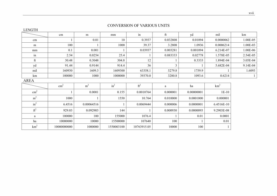
xvii
CONVERSION OF VARIOUS UNITS LENGTH
cm m mm in ft yd mil km cm 1 0.01 10 0.3937 0.032808 0.01094 0.0000062 1.00E-05 m 100 1 1000 39.37 3.2808 1.0936 0.0006214 1.00E-03
mm 0.1 0.001 1 0.03937 0.003281 0.001094 6.214E-07 1.00E-06 in 2.54 0.0254 25.4 1 0.083333 0.02778 1.578E-05 2.54E-05 ft 30.48 0.3048 304.8 12 1 0.3333 1.894E-04 3.05E-04 yd 91.44 0.9144 914.4 36 3 1 5.682E-04 9.14E-04 mil 160930 1609.3 1609300 63358.1 5279.8 1759.9 1 1.6093 km 100000 1000 1000000 39370.0 3280.8 1093.6 0.6214 1
AREA
cm2 m2 in2 ft2 a ha km2
cm2 1 0.0001 0.155 0.0010764 0.000001 0.00000001 1E-10
m2 1000 1 1550 10.764 0.010000 0.0001000 0.000001
in2 6.4516 0.00064516 1 0.0069444 0.000006 0.0000001 6.4516E-10
ft2 929.03 0.092903 144 1 0.000930 0.0000093 9.2903E-08
a 100000 100 155000 1076.4 1 0.01 0.0001 ha 10000000 10000 15500000 107640 100 1 0.01
km2 10000000000 1000000 1550003100 10763915.05 10000 100 1
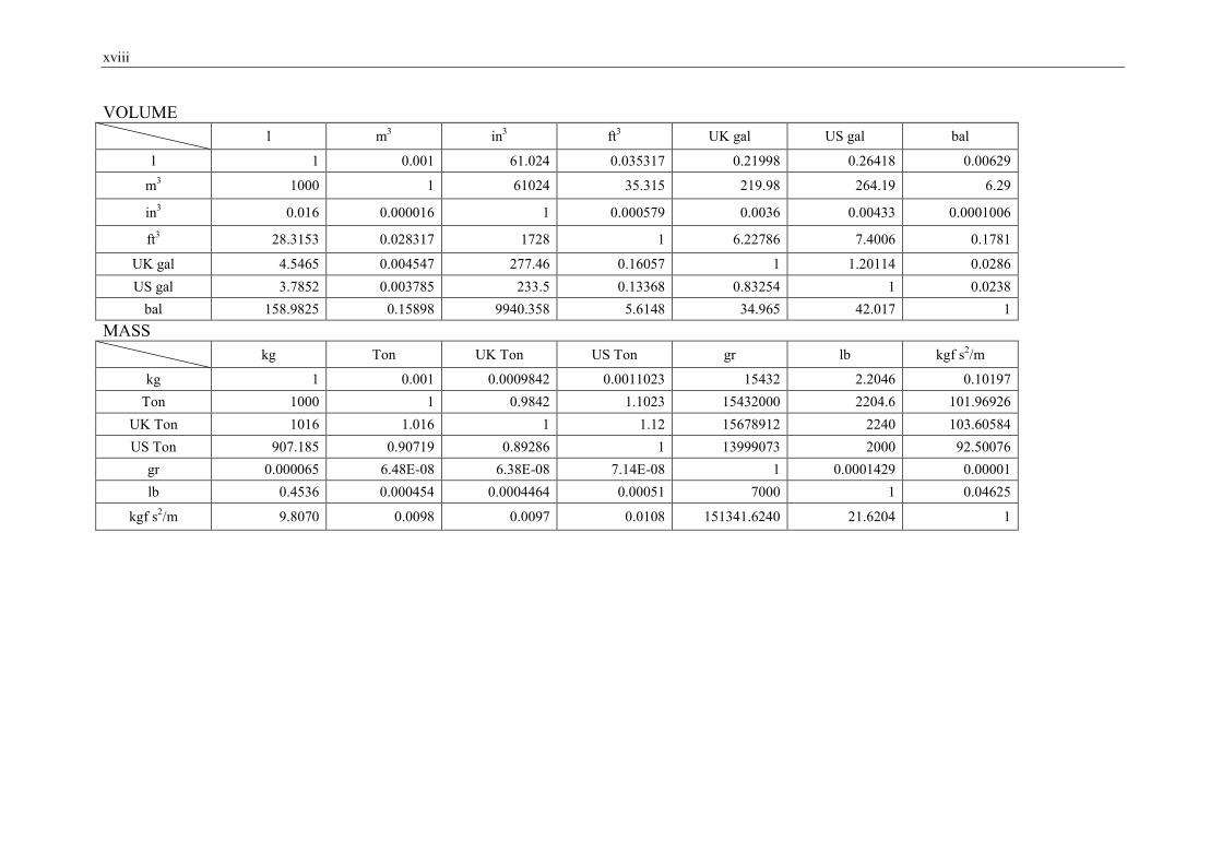
xviii
VOLUME
l m3 in3 ft3 UK gal US gal bal
l 1 0.001 61.024 0.035317 0.21998 0.26418 0.00629
m3 1000 1 61024 35.315 219.98 264.19 6.29
in3 0.016 0.000016 1 0.000579 0.0036 0.00433 0.0001006
ft3 28.3153 0.028317 1728 1 6.22786 7.4006 0.1781
UK gal 4.5465 0.004547 277.46 0.16057 1 1.20114 0.0286 US gal 3.7852 0.003785 233.5 0.13368 0.83254 1 0.0238
bal 158.9825 0.15898 9940.358 5.6148 34.965 42.017 1 MASS
kg Ton UK Ton US Ton gr lb kgf s2/m
kg 1 0.001 0.0009842 0.0011023 15432 2.2046 0.10197 Ton 1000 1 0.9842 1.1023 15432000 2204.6 101.96926
UK Ton 1016 1.016 1 1.12 15678912 2240 103.60584 US Ton 907.185 0.90719 0.89286 1 13999073 2000 92.50076
gr 0.000065 6.48E-08 6.38E-08 7.14E-08 1 0.0001429 0.00001 lb 0.4536 0.000454 0.0004464 0.00051 7000 1 0.04625
kgf s2/m 9.8070 0.0098 0.0097 0.0108 151341.6240 21.6204 1
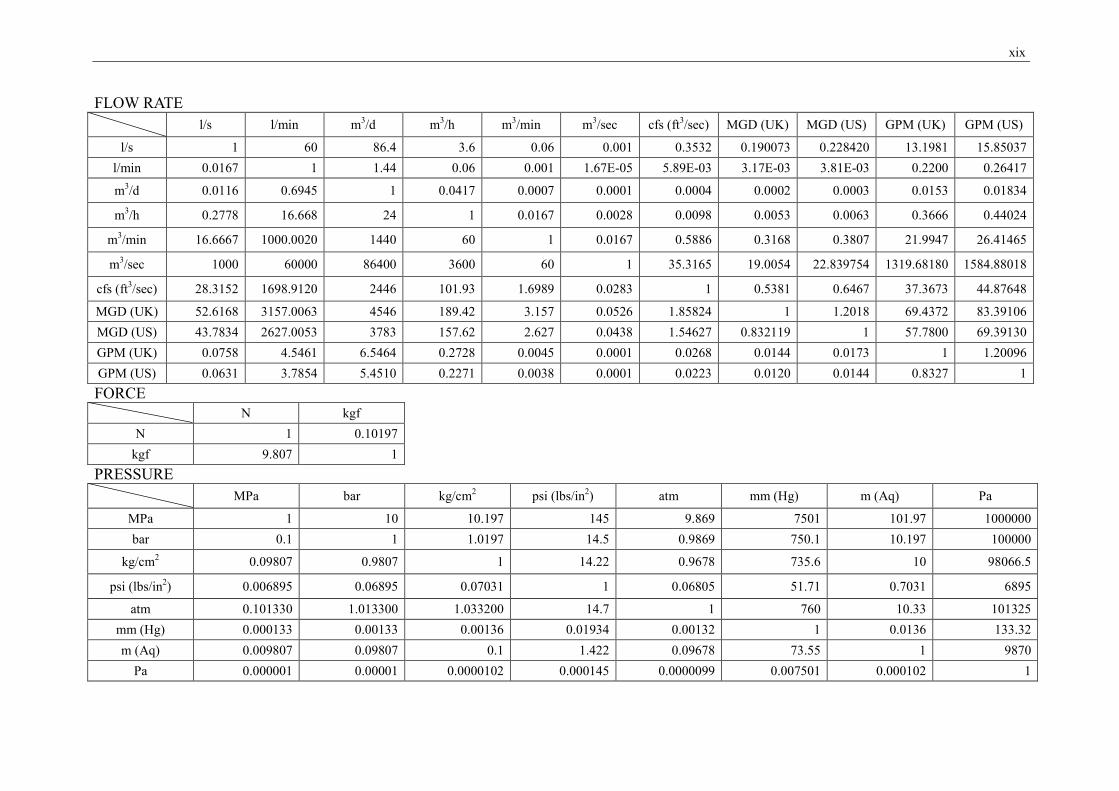
xix
FLOW RATE
l/s l/min m3/d m3/h m3/min m3/sec cfs (ft3/sec) MGD (UK) MGD (US) GPM (UK) GPM (US)
l/s 1 60 86.4 3.6 0.06 0.001 0.3532 0.190073 0.228420 13.1981 15.85037 l/min 0.0167 1 1.44 0.06 0.001 1.67E-05 5.89E-03 3.17E-03 3.81E-03 0.2200 0.26417
m3/d 0.0116 0.6945 1 0.0417 0.0007 0.0001 0.0004 0.0002 0.0003 0.0153 0.01834
m3/h 0.2778 16.668 24 1 0.0167 0.0028 0.0098 0.0053 0.0063 0.3666 0.44024
m3/min 16.6667 1000.0020 1440 60 1 0.0167 0.5886 0.3168 0.3807 21.9947 26.41465
m3/sec 1000 60000 86400 3600 60 1 35.3165 19.0054 22.839754 1319.68180 1584.88018
cfs (ft3/sec) 28.3152 1698.9120 2446 101.93 1.6989 0.0283 1 0.5381 0.6467 37.3673 44.87648
MGD (UK) 52.6168 3157.0063 4546 189.42 3.157 0.0526 1.85824 1 1.2018 69.4372 83.39106 MGD (US) 43.7834 2627.0053 3783 157.62 2.627 0.0438 1.54627 0.832119 1 57.7800 69.39130 GPM (UK) 0.0758 4.5461 6.5464 0.2728 0.0045 0.0001 0.0268 0.0144 0.0173 1 1.20096 GPM (US) 0.0631 3.7854 5.4510 0.2271 0.0038 0.0001 0.0223 0.0120 0.0144 0.8327 1 FORCE
N kgf N 1 0.10197
kgf 9.807 1 PRESSURE
MPa bar kg/cm2 psi (lbs/in2) atm mm (Hg) m (Aq) Pa
MPa 1 10 10.197 145 9.869 7501 101.97 1000000 bar 0.1 1 1.0197 14.5 0.9869 750.1 10.197 100000
kg/cm2 0.09807 0.9807 1 14.22 0.9678 735.6 10 98066.5
psi (lbs/in2) 0.006895 0.06895 0.07031 1 0.06805 51.71 0.7031 6895
atm 0.101330 1.013300 1.033200 14.7 1 760 10.33 101325 mm (Hg) 0.000133 0.00133 0.00136 0.01934 0.00132 1 0.0136 133.32 m (Aq) 0.009807 0.09807 0.1 1.422 0.09678 73.55 1 9870
Pa 0.000001 0.00001 0.0000102 0.000145 0.0000099 0.007501 0.000102 1
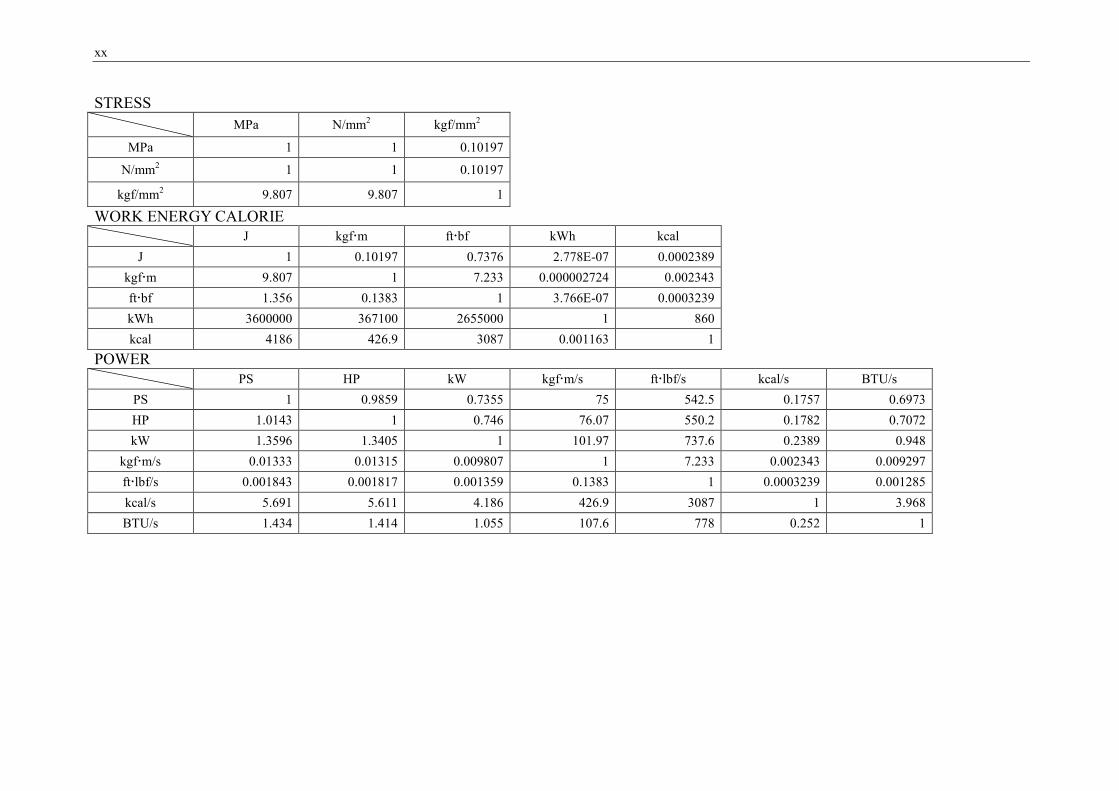
xx
STRESS
MPa N/mm2 kgf/mm2
MPa 1 1 0.10197
N/mm2 1 1 0.10197
kgf/mm2 9.807 9.807 1
WORK ENERGY CALORIE
J kgfm ftbf kWh kcal J 1 0.10197 0.7376 2.778E-07 0.0002389
kgfm 9.807 1 7.233 0.000002724 0.002343 ftbf 1.356 0.1383 1 3.766E-07 0.0003239 kWh 3600000 367100 2655000 1 860 kcal 4186 426.9 3087 0.001163 1
POWER
PS HP kW kgfm/s ftlbf/s kcal/s BTU/s PS 1 0.9859 0.7355 75 542.5 0.1757 0.6973 HP 1.0143 1 0.746 76.07 550.2 0.1782 0.7072 kW 1.3596 1.3405 1 101.97 737.6 0.2389 0.948
kgfm/s 0.01333 0.01315 0.009807 1 7.233 0.002343 0.009297 ftlbf/s 0.001843 0.001817 0.001359 0.1383 1 0.0003239 0.001285 kcal/s 5.691 5.611 4.186 426.9 3087 1 3.968 BTU/s 1.434 1.414 1.055 107.6 778 0.252 1
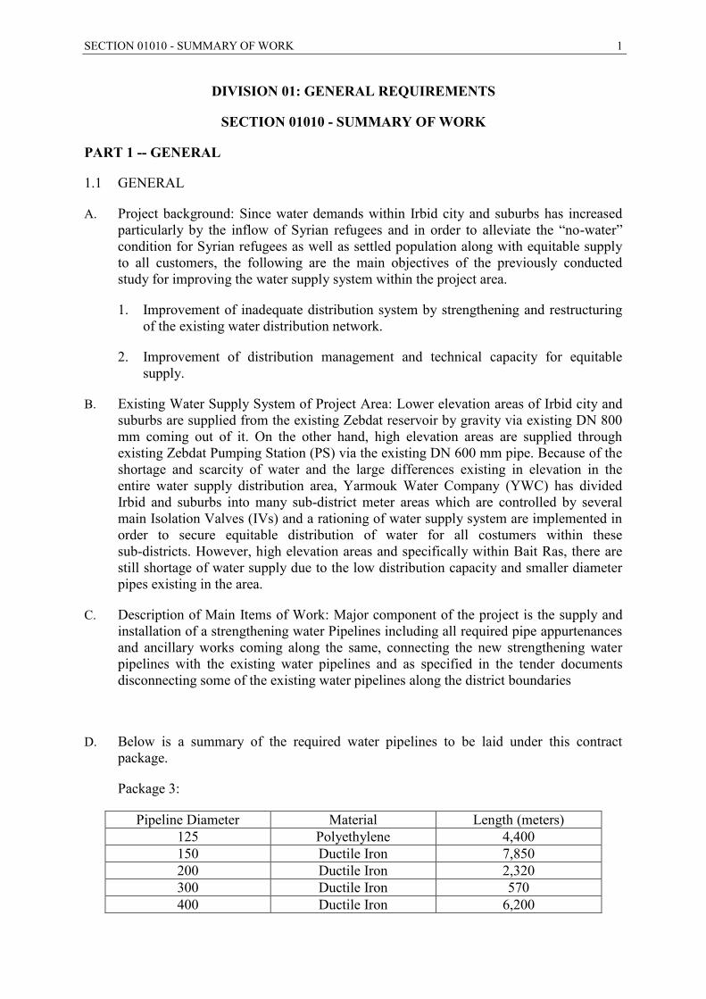
SECTION 01010 - SUMMARY OF WORK 1
DIVISION 01: GENERAL REQUIREMENTS
SECTION 01010 - SUMMARY OF WORK
PART 1 -- GENERAL
1.1 GENERAL
A. Project background: Since water demands within Irbid city and suburbs has increased particularly by the inflow of Syrian refugees and in order to alleviate the “no-water” condition for Syrian refugees as well as settled population along with equitable supply to all customers, the following are the main objectives of the previously conducted study for improving the water supply system within the project area.
1. Improvement of inadequate distribution system by strengthening and restructuring of the existing water distribution network.
2. Improvement of distribution management and technical capacity for equitable supply.
B. Existing Water Supply System of Project Area: Lower elevation areas of Irbid city and suburbs are supplied from the existing Zebdat reservoir by gravity via existing DN 800 mm coming out of it. On the other hand, high elevation areas are supplied through existing Zebdat Pumping Station (PS) via the existing DN 600 mm pipe. Because of the shortage and scarcity of water and the large differences existing in elevation in the entire water supply distribution area, Yarmouk Water Company (YWC) has divided Irbid and suburbs into many sub-district meter areas which are controlled by several main Isolation Valves (IVs) and a rationing of water supply system are implemented in order to secure equitable distribution of water for all costumers within these sub-districts. However, high elevation areas and specifically within Bait Ras, there are still shortage of water supply due to the low distribution capacity and smaller diameter pipes existing in the area.
C. Description of Main Items of Work: Major component of the project is the supply and installation of a strengthening water Pipelines including all required pipe appurtenances and ancillary works coming along the same, connecting the new strengthening water pipelines with the existing water pipelines and as specified in the tender documents disconnecting some of the existing water pipelines along the district boundaries
D. Below is a summary of the required water pipelines to be laid under this contract package.
Package 3:
Pipeline Diameter Material Length (meters) 125 Polyethylene 4,400 150 Ductile Iron 7,850 200 Ductile Iron 2,320 300 Ductile Iron 570 400 Ductile Iron 6,200
2 SECTION 01010 - SUMMARY OF WORK
1.2 LOCATION
A. The Project is located in the middle of Irbid City.
1.3 CLIMATE
A. In the project area, the summer is hot and dry with low humidity, while the winter is moderate to cold.
1.4 REQUIREMENTS
A. The WORK to be performed under this Contract shall consist of furnishing plant, tools, equipment, materials, supplies, and manufactured articles, and furnishing all labor, transportation, and services, including fuel, power, water, and essential communications, and performing all work or other operations required for the fulfillment of the Contract in strict accordance with the Contract Documents. The WORK shall be complete, and all work, materials, and services not expressly indicated or called for in the Contract Documents which may be necessary for the complete and proper construction of the WORK in good faith shall be provided by the Contractor as though originally so indicated, at no increase in cost to the Employer.
1.5 SCOPE OF WORK
A. The scope of work include:
1. Construction of ductile iron and PE water pipelines including all required pipe appurtenances and ancillary as described in part 1
2. Proper isolation for the proposed DMAs at the boundary.
3. Reconnect the existing water network with the new strengthening pipelines.
1.6 WORK SEQUENCE
A. To minimize the contract supervision, the Contractor is expected to coordinate with the Engineer before implementation of any connection, disconnection and construction. The Contractor work plan shall show the proposed sequence of work.
1.7 CONTRACTOR USE OF SITES
A. The Contractor's use of the Sites shall be limited to its construction operations, including on-Site storage of materials, on-Site fabrication facilities, and field offices.
B. The Contractor shall use only the indicated portion of the Site for any of its construction operations.
SECTION 01010 - SUMMARY OF WORK 3
1.8 OUTAGE PLAN AND REQUESTS
A. Unless the Contract Documents indicate otherwise, the Contractor shall not remove from service, de-energize, or modify water and reclaimed water pipelines or any other facility without permission from the Engineer.
1. The maximum duration of any outage shall be 4 hours.
2. The minimum time between outages shall be 8 hours.
B. Where the WORK requires modifications to existing facilities or construction of new facilities and connection of new facilities to existing facilities, the Contractor shall submit a detailed outage plan and schedule for the Engineer's approval a minimum of 2 weeks in advance of the time that such outage is planned.
C. A completed System Outage Request form (blank furnished by the Engineer) shall accompany each outage plan. The outage plans shall be coordinated with the construction schedule and shall meet the restrictions and conditions of the Contract Documents. All costs for preparing and implementing the outage plans shall be at no increase in cost to the Employer.
D. The Engineer shall be notified in writing at least one week in advance of the required outage if the schedule for performing the work has changed or if revisions to the outage plan are required.
1.9 EMPLOYER USE OF SITES
A. The Employer may utilize all or part of the existing facilities during the entire period of construction for the conduct of the Employer's normal operations. The Contractor shall cooperate and coordinate with the Employer to facilitate the Employer's operations and to minimize interference with the Contractor's operations at the same time. In any event, the Employer shall be allowed access to the Site during the period of construction.
1.10 PROJECT MEETINGS
A. Pre-construction Conference:
1. Prior to the commencement of WORK at the Site, a pre-construction conference will be held at a mutually agreed time and place. The conference shall be attended by the Contractor's Project Manager, its superintendent, and its Subcontractors as the Contractor deems appropriate. Other attendees will be:
a. Engineer and the Resident Project Representative.
b. Representatives of Employer.
c. Governmental representatives as appropriate.
d. Others as requested by Contractor, Employer, or Engineer.
2. The Contractor shall bring the preconstruction conference submittals in accordance with Section 01300 - Contractor Submittals.
4 SECTION 01010 - SUMMARY OF WORK
3. The purpose of the conference is to designate responsible personnel and establish a working relationship. Matters requiring coordination will be discussed and procedures for handling such matters established. The complete agenda will be furnished to the Contractor prior to the meeting date. However, the Contractor should be prepared to discuss all of the items listed below:
a. Status of Contractor's insurance and bonds.
b. Contractor's tentative schedules.
c. Transmittal, review, and distribution of Contractor's submittals.
d. Processing applications for payment.
e. Maintaining record documents.
f. Critical work sequencing.
g. Field decisions and Change Orders.
h. Use of Site, office and storage areas, security, housekeeping, and Employer's needs.
i. Major equipment deliveries and priorities.
j. Contractor's assignments for safety and first aid.
k. Daily Report Form which the Engineer will furnish.
l. Submittal Transmittal Form which the Engineer will furnish.
4. The Engineer will preside at the preconstruction conference and will arrange for keeping and distributing the minutes to all persons in attendance.
5. The Contractor and its Subcontractors should plan on the conference taking no less than three full working days.
B. Progress Meetings:
1. The Contractor shall schedule and hold regular on-Site progress meetings at least monthly and at other times as requested by Engineer or as required by progress of the WORK. The Contractor, Engineer, and all Subcontractors active on the Site shall attend each meeting. Contractor may at its discretion request attendance by representatives of its Suppliers, manufacturers, and other Subcontractors.
2. The Engineer will preside at the progress meetings and will arrange for keeping and distributing the minutes. The purpose of the meetings is to review the progress of the WORK, maintain coordination of efforts, discuss changes in scheduling, and resolve other problems which may develop. During each meeting, the Contractor shall present any issues which may impact its progress with a view to resolve these issues expeditiously.

SECTION 01010 - SUMMARY OF WORK 5
1.11 CONTRACT DRAWINGS
A. The Contract Drawings are those listed in these documents, together with any other Drawings, which may be issued by the Engineer during the construction period of the Contract.
- END OF SECTION -
6 SECTION 01020 – STANDARD SPECIFICATIONS
SECTION 01020 – STANDARD SPECIFICATIONS
PART 1 -- GENERAL
1.1 GENERAL
A. Wherever in these Specifications references are made to the standards, specifications, or other published data of the various international, national, regional, or local organizations, such organizations may be referred to by their acronym or abbreviation only. As a guide to the user of these Specifications, the following acronyms or abbreviations which may appear in these Specifications shall have the meanings indicated herein.
1.2 ABBREVIATIONS
A. Throughout the specifications reference is made to DIN, ISO, BS and ASTM standard specifications, including the EN versions. In all such cases reference to such standard shall be deemed to include the wording "or equivalent standard, subject to the approval by the Engineer".
B. In cases where the Contractor propose to submit alternative standards for approval, he shall allow sufficient time for the Engineer to check such standards and for carrying out any test, as directed by the Engineer, in order to confirm that materials supplied under the alternative standards are acceptable. The Contractor must provide two English copies of all standards for use during the Contract. The Engineer may accept electronic format for the standards if such is available.
C. No claim for delay will be accepted arising as a result of time required for conducting any tests. It is the Contractor’s responsibility to ensure that sufficient time is available in advance to test any materials being required for the Work, which are not in conformity with recognized standards.
D. The Contractor shall supply the Engineer within (6) weeks after Contract Award with one copy of all the standards to which the items mentioned in the documents are manufactured or installed. This Clause shall not apply to manufacturing standards for items, which the Contractor is installing only. Electronic format of standards may be acceptable to the Engineer.
E. For each manufacturer/supplier proposed by the Contractor, he shall submit to the Engineer a comparison sheet which clearly sets out the standards and specifications of that particular product, indicating the compliance with the Specifications and any deviation there from.
- END OF SECTION -

SECTION 01025 –MEASUREMENT AND PAYMENT 7
SECTION 01025 –MEASUREMENT AND PAYMENT
PART 1 -- GENERAL
1.1 DESCRIPTION
A. Payment for the various bid items as defined in Volume Three (3), Bill of Quantities, shall include all compensation to be received by the Contractor for furnishing all tools, equipment, supplies, and manufactured articles, and for all labor, operations, and incidentals appurtenant to the items of work being described, as necessary to complete the various items of the WORK all in accordance with the requirements of the Contract Documents, including all appurtenances thereto, and including all costs of permits and cost of compliance with the regulations of public agencies having jurisdiction. No separate payment will be made for any item that is not specifically set forth in the Bill of Quantities, and all costs therefore shall be included in the prices named in the Bill of Quantities for the various appurtenant items of work.
1.2 CONTRACT METHOD
A. The WORK hereunder will be constructed under unit price items.
- END OF SECTION -
8 SECTION 01090 – REFERENCE STANDARDS
SECTION 01090 – REFERENCE STANDARDS
PART 1 -- GENERAL
1.1 GENERAL
A. Titles of Sections and Paragraphs: Titles and subtitles accompanying specification sections and paragraphs are for convenience and reference only, and do not form a part of the specifications.
B. Applicable Publications: Whenever in these Specifications references are made to published specifications, codes, standards, or other requirements, it shall be understood that wherever no date is specified, only the latest specifications, standards, or requirements of the respective issuing agencies which have been published as of the date that the Contract is advertised for bids shall apply; except to the extent that said standards or requirements may be in conflict with applicable laws, ordinances, or governing codes. No requirements set forth in the Specifications or shown on the Drawings will be waived because of any provision of, or omission from, said standards or requirements.
C. Specialists, Assignments: In certain instances, specification text requires (or implies) that specific work is to be assigned to specialists or expert entities, who must be engaged for the performance of that work. Such assignments shall be recognized as special requirements over which the Contractor has no choice or option. These requirements shall not be interpreted so as to conflict with the enforcement of building codes and similar regulations governing the WORK; also they are not intended to interfere with local union jurisdiction settlements and similar conventions. Such assignments are intended to establish which party or entity involved in a specific unit of work is recognized as "expert" for the indicated construction processes or operations. Nevertheless, the final responsibility for fulfillment of the entire set of contract requirements remains with the Contractor.
1.2 REFERENCE SPECIFICATIONS, CODES, AND STANDARDS
A. The Contractor shall construct the WORK in accordance with the Contract Documents and the referenced portions of those referenced codes, standards, and specifications.
- END OF SECTION –
SECTION 01300 - CONTRACTOR SUBMITTALS 9
SECTION 01300 - CONTRACTOR SUBMITTALS
PART 1 -- GENERAL
1.1 GENERAL
A. Wherever submittals are required in the Contract Documents, submit them to the Engineer.
B. Within 14 days after the date of commencement as stated in the Notice to Proceed, the Contractor shall submit the following items to the Engineer for review:
1. A preliminary schedule of Shop Drawings, Samples, and proposed Substitutes ("Or-Equal") submittals listed in the Bid.
2. A list of all permits and licenses the Contractor shall obtain indicating the agency required to grant the permit and the expected date of submittal for the permit and required date for receipt of the permit.
1.2 PRECONSTRUCTION CONFERENCE SUBMITTALS
A. At the preconstruction conference referred to in Section 01010 - Summary of Work, the Contractor shall submit the following items to the Engineer for review:
1. A preliminary schedule of Shop Drawings, Samples, and proposed Substitute ("Or-Equal") submittals listed in the Bid.
2. A list of all permits and licenses the Contractor shall obtain indicating the agency required to grant the permit, the expected date of submittal for the permit, and required date for receipt of the permit.
3. A 60-day plan of operation in accordance with Section 01311 - CPM Construction Schedule.
4. A project overview bar chart in accordance with Section 01311 - CPM Construction Schedule.
5. A detailed layout of the field office required under Section 01590 - Field Office, Equipment, Engineer’s Transportation and Services.
1.3 SHOP DRAWINGS
A. Wherever called for in the Contract Documents, or where required by the Engineer, the Contractor shall furnish to the Engineer for review, 2 copies plus one reproducible copy plus the number of copies needed by the Contractor, of each Shop Drawing submittal. The term "Shop Drawings" as used herein shall be understood to include detail design calculations, shop-prepared drawings, fabrication, and installation drawings, erection drawings, lists, graphs, catalog sheets, data sheets, and similar items. Whenever the Contractor is required to submit design calculations as part of a submittal, such calculations shall bear the signature and seal of a professional engineer registered in the appropriate branch of engineering.
10 SECTION 01300 - CONTRACTOR SUBMITTALS
B. Shop drawing submittals shall be accompanied by the Engineer's standard submittal transmittal form, a reproducible copy of which is available from the Engineer. Any submittal not accompanied by such a form, or where all applicable items on the form are not completed, will be returned for resubmitted.
C. Organization
1. A single submittal transmittal form shall be used for each technical specification section or item or class of material or equipment for which a submittal is required. A single submittal covering multiple sections will not be acceptable, unless the primary specification references other sections for components.
2. On the transmittal form, index the components of the submittal and insert tabs in the submittal to match the components. Relate the submittal components to Specification paragraph and subparagraph, Drawing number, detail number, schedule title, as applicable.
3. Unless indicated otherwise, terminology and equipment names and numbers used in submittals shall match the Contract Documents.
D. Format
1. Minimum sheet size shall be 21.5 cm by 28cm. Maximum sheet size shall be 60 cm by 90 cm. Every page in a submittal shall be numbered in sequence. Each copy of a submittal shall be collated a stapled or bound, as appropriate. The Engineer will not collate copies.
2. Where product data from a manufacturer is submitted, clearly mark which model is proposed, with all pertinent data capacities, dimensions, clearances, diagrams, controls, connections, anchorage, and supports. Sufficient level of detail shall be presented for assessment of compliance with the Contract Documents.
3. Each submittal shall be assigned a unique number. Submittals shall be numbered sequentially. The submittal numbers shall be clearly noted on the transmittal. Original submittals shall be assigned a numeric submittal number. Resubmittals shall bear an alpha-numeric system which consists of the number assigned to the original submittal for that item followed by a letter of the alphabet to represent that it is a subsequent submittal of the original. For example, if submittal 25 requires a resubmittal, the first resubmittal will bear the designation (25-A) and the second resubmittal will bear the designation (25-B) and so on.
E. Disorganized submittals which do not meet the requirements above will be returned without review.
F. Except as may otherwise be indicated herein, the Engineer will return prints of each submittal to the Contractor with its comments noted thereon, within 30 calendar days following receipt by the Engineer. It is considered reasonable that the Contractor shall make a complete and acceptable submittal to the Engineer by the second submission of a submittal item. The Employer reserves the right to charge the Contractor for the additional costs of the Engineer's review beyond the second submittal. The Engineer's maximum review period for each submittal, including all resubmittals, will be 30 days

SECTION 01300 - CONTRACTOR SUBMITTALS 11
per submittal. Thus, for a submittal that requires two resubmittals before it is complete, the maximum review period for that submittal could be 90 days.
G. If a submittal is returned to the Contractor marked "NO EXCEPTIONS TAKEN," formal revision and resubmission of said submittal will not be required.
H. If a submittal is returned marked "MAKE CORRECTIONS NOTED," Contractor shall make the corrections on the submittal, but formal revision and resubmission of said submittal will not be required.
I. If a submittal is returned marked "AMEND-RESUBMIT," the Contractor shall revise said submittal and shall resubmit the required number of copies of said revised submittal to the Engineer for review.
J. If a submittal is returned marked "REJECTED-RESUBMIT," it shall mean that the submitted material or product does not satisfy the specification, the submittal is so incomplete that it cannot be reviewed, or is a substitution request not submitted in accordance with Section 01600 - Products, Materials, Equipment, and Substitutions. The Contractor shall prepare a new submittal and shall resubmit the required number of copies of said revised submittal to the Engineer for review.
K. Fabrication of an item shall be commenced only after the Engineer has reviewed the pertinent submittals and returned copies to the Contractor marked either "NO EXCEPTIONS TAKEN" or MAKE CORRECTIONS NOTED." Corrections indicated on submittals shall be considered as changes necessary to meet the requirements of the Contract Documents and shall not be taken as changes to the contract requirements.
L. All submittals shall be carefully reviewed by an authorized representative of the Contractor, prior to submission to the Engineer. Each submittal shall be dated, signed, and certified by the Contractor, as being correct and in strict conformance with the Contract Documents. In the case of Shop Drawings, each sheet shall be so dated, signed, and certified. The Engineer will only review submittals which have been so certified by the Contractor. All non-certified submittals will be returned to the Contractor without action taken by the Engineer, and any delays caused thereby shall be the total responsibility of the Contractor.
M. The Engineer's review of submittals shall not relieve the Contractor of the entire responsibility for the correctness of details and dimensions. The Contractor shall assume all responsibility and risk for any misfits due to any errors in submittals. The Contractor shall be responsible for the dimensions and the design of adequate connections and details.
1.4 CONTRACTOR'S SCHEDULE
A. The Contractor's construction schedules and reports shall be prepared and submitted to the Engineer in accordance with of Section 01311 - CPM Construction Schedule.
1.5 SAMPLES
A. Whenever in the Specifications samples are required, the Contractor shall submit not less than 3 samples of each item or material to the Engineer for acceptance.

12 SECTION 01300 - CONTRACTOR SUBMITTALS
B. Unless otherwise indicated, samples, shall be submitted a minimum of 21 days prior to ordering such material.
C. Samples shall be individually and indelibly labeled or tagged, indicating thereon all specified physical characteristics and Manufacturer's name. Upon receiving acceptance of the Engineer, one set of the samples will be stamped and dated by the Engineer and returned to the Contractor, and one set of samples will be retained by the Engineer, and one set of samples shall remain at the Site until completion of the WORK.
1.6 RECORD DRAWINGS
A. The Contractor shall maintain one record set of Drawings at the Site. On these, it shall mark all project conditions, locations, configurations, and any other changes or deviations which may vary from the information represented on the original Contract Drawings, including buried or concealed construction and utility features which are revealed during the course of construction. Special attention shall be given to recording the horizontal and vertical location of all buried utilities that differ from the locations indicated, or which were not indicated on the Contract Drawings. Said record drawings shall be supplemented by any detailed sketches as necessary or directed to fully indicate the WORK as actually constructed. These master record drawings of the Contractor's representation of as-built conditions, including all revisions made necessary by addenda and change orders shall be maintained up-to-date during the progress of the WORK. Red ink shall be used for alterations and notes. Notes shall identify relevant Change Orders by number and date.
B. Copies of the record drawings shall be submitted on the 20th working day of every third month after the month in which the Notice to Proceed is given as well as on completion of WORK.
C. Record drawings shall be accessible to the Engineer at all times during the construction period.
D. Final payment will not be acted upon until the record drawings have been prepared and delivered to the Engineer. Said up-to-date record drawings shall be in the form of a set of prints with carefully plotted information overlaid.
E. Upon Substantial Completion of the WORK and prior to final acceptance, the Contractor shall finalize and deliver a reproducible set of record drawings, one prime trace, six hard copies and six electronic copies as AutoCAD version 2010 of the record drawings and four electronic copies as a GIS system format to the Engineer for transmittal to the Employer, conforming to the construction records of the Contractor. This set of drawings shall consist of corrected Drawings showing the reported location of the WORK. The information submitted by the Contractor and incorporated by the Engineer into the record drawings will be assumed to be correct, and the Contractor shall be responsible for the accuracy of such information, and for any errors or omissions which may appear on the record drawings as a result.
F. The record drawings of water and reclaimed water pipelines and their accessories shall be in AutoCAD version 2010 format (dwg files) as well as GIS format.
- END OF SECTION -
SECTION 01301 - SCHEDULE OF VALUES 13
SECTION 01301 - SCHEDULE OF VALUES
PART 1 -- GENERAL
1.1 GENERAL
A. This Section defines the process whereby the Schedule of Values shall be developed and incorporated into the cost loading function of the CPM Schedule as specified in Section 01311 – CPM Construction Schedule. Monthly progress payment amounts shall be determined from the monthly progress updates of the CPM Schedule activities.
B. The Schedule of Values shall be developed independent but simultaneous with the development of the CPM Schedule activities and logic.
1.2 PRELIMINARY SCHEDULE OF VALUES
A. The Contractor shall submit a Price Analysis List (PAL) for all major components of the Work with his Tender as contained in Volume Three (3)/ Bill of Quantities (BoQs). The listing shall include, at a minimum, the proposed value for the following major Work components:
1. Mobilization.
2. The total value of water pipelines and their accessories work.
3. The total value of each bid item as listed separately.
B. The Contractor and Engineer shall meet and jointly review the Price Analysis List (PAL) and make any adjustments in value allocations if, in the opinion of the Engineer, these are necessary to establish fair and reasonable allocation of values for the major WORK components. Front end loading will not be permitted. The Engineer may require reallocation of major WORK components from items in the above listing if in the opinion of the Engineer such reallocation is necessary. This review and any necessary revisions shall be completed within 15 days from the effective date of Notice to Proceed.
1.3 DETAILED SCHEDULE OF VALUES
A. The Contractor shall prepare and submit a detailed Schedule of Values to the Engineer within 30 days from the date of Notice to Proceed. The detailed Schedule of Values shall be based on the accepted Price Analysis List (PAL) for major WORK components. Because the ultimate requirement is to develop a detailed Schedule of Values sufficient to determine appropriate monthly progress payment amounts through cost loading of the CPM Schedule activities, sufficient detailed breakdown shall be provided to meet this requirement.
1. The minimum detail of breakdown of the major WORK components is indicated in the Price Analysis List (PAL). Greater detail shall be provided as directed by the Engineer.

14 SECTION 01301 - SCHEDULE OF VALUES
All other WORK not specifically included in the Price Analysis List (PAL) shall be broken down as necessary for establishment of pay and Schedule activity items.
2. The Contractor and Engineer shall meet and jointly review the detailed Price Analysis List (PAL) within 35 days from the date of Notice to Proceed. The value allocations and extent of detail shall be reviewed to determine any necessary adjustments to the values and to determine if sufficient detail has been proposed to allow acceptable cost loading of the CPM Schedule activities. Any adjustments deemed necessary to the value allocation or level of detail shall be made by the Contractor and a revised detailed Schedule of Values shall be submitted within 40 days from the date of Notice to Proceed.
3. Following acceptance of the detailed Schedule of Values, the Contractor shall incorporate the values into the cost loading portion of the CPM Schedule. The CPM activities and logic shall have been developed concurrent with development of the detailed Schedule of Values; however, it shall be necessary to adjust the detailed Schedule of Values to correlate to individual Schedule activities. It is anticipated that instances will occur, due to the independent but simultaneous development of the Schedule of Values and the CPM Schedule activities, where interfacing these two documents will require changes to each document. Schedule activities may need to be added to accommodate the detail of the Schedule of Values. Schedule of Value items may need to be added to accommodate the detail of the CPM Schedule activities. Where such instances arise, the Contractor shall propose changes to the Schedule of Values and to the CPM Schedule activities to satisfy the CPM Schedule cost loading requirements.
1.4 CROSS REFERENCE LISTING
A. To assist in the correlation of the Schedule of Values and the CPM Schedule, the Contractor shall provide a Cross Reference Listing which shall be furnished in two parts. The first part shall list each Scheduled Activity with the breakdown of the respective valued items making up the total cost of the activity. The second part shall list the valued item with the respective Scheduled Activity or Activities that make up the total cost indicated. In the case where a number of schedule items make up the total cost for a valued item (shown in the Schedule of Values) the total cost for each scheduled item should be indicated.
B. These listings shall be updated and submitted in conjunction with the CPM monthly submittals as stated in Specification Section 01311- CPM Construction Schedule.
C. Approved change orders reflected in the CPM Schedule shall be incorporated into the Schedule of Values as a single unit identified by the change order number.
1.5 CHANGES TO SCHEDULE OF VALUES
A. Changes to the CPM Schedule which add activities not included in the original schedule but included in the original WORK (schedule omissions) shall have values assigned as approved by the Engineer. Other activity values shall be reduced to provide equal value adjustment increases for added activities as approved by the Engineer.
SECTION 01301 - SCHEDULE OF VALUES 15
B. In the event that the Contractor and Engineer agree to make adjustments to the original Schedule of Values because of inequities discovered in the original accepted detailed Schedule of Values, increases and equal decreases to values for activities may be made.
1.6 TIMELINESS OF SUBMITTALS
A. The Schedule of Values information is an integral part of the scheduling and reporting under Section 01311 “CPM Construction Schedule” and the progress payment information. As such, it is critical information to evaluating the project's progress and the proper planning of the Employer's and Engineer's work effort as well as their financial obligations associated with this project. Accordingly, if any submittal required by this Section is found to be incomplete or is submitted later than required, the processing of progress payments and Contractor submittals will be affected. Such delays shall not be considered as a basis for extension of the Contract Time.
- END OF SECTION -
16 SECTION 01311 - CPM CONSTRUCTION SCHEDULE
SECTION 01311 - CPM CONSTRUCTION SCHEDULE
PART 1 -- GENERAL
1.1 GENERAL
A. Scheduling of the WORK shall be performed by the Contractor in accordance with the requirements of this Section.
B. Development of the schedule, the cost loading of the schedule, monthly payment requisitions and project status reporting requirements of the Contract shall employ computerized Critical Path Method (CPM) scheduling. The CPM Schedule shall be cost loaded based on the schedule of values as approved by the Engineer in accordance with the requirements of Section 01301 - Schedule of Values. The CPM schedule and all reports should be prepared with the current version of Primavera Project Planner (P6) software. Where submittals are required hereunder, the Contractor shall submit four copies of each submittal item.
1.2 QUALIFICATIONS
A. The Contractor shall attach a statement of computerized CPM capability to the Bid Forms and shall verify that either the Contractor has in-house capability qualified to use CPM technique and the Primavera P6 software or that the Contractor will arrange for the services of a CPM consultant so qualified. In either event the statement shall identify the individual who will perform the CPM scheduling. Capability shall be verified by description of construction projects on which the individual has successfully applied computerized CPM and shall include at least two projects of similar nature, scope and value not less than one-half the Total Bid Price of this project. The statement shall also identify the contact persons for the referenced projects with current telephone and address information.
1.3 INITIAL SCHEDULE SUBMITTALS
A. The Contractor shall submit two short-term schedule documents at the Preconstruction Conference that shall serve as the Contractor's Plan of Operation for the initial 60 day period of the Contract Time and to identify the manner in which the Contractor intends to complete all WORK within the Contract Time.
1. 60 Day Plan of Operation: During the initial 60 days of the Contract Time, the Contractor shall conduct operations in accordance with a 60 day bar chart type of plan of operation. The bar chart so prepared shall show the accomplishment of the Contractor's early activities (mobilization, permits, submittals necessary for early material and equipment procurement, submittals necessary for long lead equipment procurement, CPM submittals, initial Site work and other submittals and activities required in the first 60 days).
2. Project Overview Bar Chart: The overview bar chart shall indicate the major components of the WORK and the sequence relations between major components and subdivisions of major components. The overview bar chart shall indicate the relationships and time frames in which the various components of the WORK will be made substantially complete and placed into service in order to meet the project milestones. Sufficient detail shall be included for the identification of subdivisions
SECTION 01311 - CPM CONSTRUCTION SCHEDULE 17
of major components. Planned durations and start dates shall be indicated for each work item subdivision. Each major component and subdivision component shall be accurately plotted on time scale sheets not to exceed A1 in size. Not more than four sheets shall be employed to represent this overview information.
B. The Engineer and the Contractor shall meet to review and discuss the 60-day plan of operation and project overview bar chart within 5 days after submittal to the Engineer. The Engineer's review and comment on the schedules will be limited to conformance with the sequencing and milestone requirements in the Contract Documents. The Contractor shall make corrections to the schedules necessary to comply with the requirements and shall adjust the schedules to incorporate any missing information requested by the Engineer.
1.4 CPM SCHEDULE SUBMITTALS
A. Original CPM Schedule Submittal: With 21 days after the commencement date stated in the Notice to Proceed, the Contractor shall submit for review by the Engineer a hard copy of the CPM Schedule and the Computerized Schedule Report tabulations. The Contractor shall also submit a CD or flash memory (memory stick) that contains all of the schedule submittal information. The disk shall contain data compatible with Primavera P6 to generate network diagrams and schedule reports identical to the hard copies submitted. This submittal shall have already been reviewed and approved by the Contractor's Project Manager, Project Superintendent, and the Project Estimator prior to submission. The Network Diagram shall describe the activities to be accomplished and their logical relationships and show the critical path. The Contractor's attention is directed to the requirement that the schedule shall contain sufficient detail and information to cost load the CPM schedule in accordance with the approved schedule of values under Section 01301- Schedule of Values . Each installation and Site work activity shall be cost loaded as indicated.
B. All float in the schedule shall belong to the project. The Computerized Schedule Report tabulations shall include the following:
1. Report of activities sorted by activity number.
2. Report of activities sorted by early start date.
3. Report of activities sorted by total float.
4. Report of activities sorted by responsibility code. Responsibility codes shall be established for the Contractor, Engineer, Employer, subcontractors, suppliers, etc. These codes shall be identified in the Network Diagram.
5. A successor-predecessor report which shall identify the successor and predecessor activities for each activity and ties between schedule activities.
C. Original CPM Schedule Review Meeting: The Contractor shall, within 30 days from the commencement date stated in the Notice to Proceed, meet with the Engineer to review the original CPM schedule submittal. The Contractor shall have the Project Manager and the Project Superintendent in attendance. The Engineer's review will be limited to the conformance to the Contract Documents. However, the review may also include:

18 SECTION 01311 - CPM CONSTRUCTION SCHEDULE
1. Clarifications of the design intent, process, and startup requirements.
2. Directions to include activities and information missing from the submittal.
3. Requests to the Contractor to clarify the schedule.
D. Revisions to the Original CPM Schedule: Within 40 days after the commencement date stated in the Notice to Proceed, the Contractor shall have revised the original CPM schedule submittal to address all review comments from the original CPM schedule review meeting and resubmit the network diagrams and reports for the Engineer's review. The Engineer, within 7 days from the date that the Contractor submitted the revised schedule will either (1) accept the schedule and cost loaded activities as submitted, or (2) advise the Contractor in writing to review any part or parts of the schedule which either do not meet the Contract requirements or are unsatisfactory for the Engineer to monitor the project's progress and status or evaluate monthly payment requests by the Contractor. The Engineer may accept the schedule with conditions that the first monthly CPM schedule update be revised to correct deficiencies identified. When the schedule is accepted, it shall be considered as the "Original CPM Construction Schedule" until an updated schedule has been submitted. The Employer reserves the right to require that the Contractor adjust, add to, or clarify any portion of the schedule which may later be discovered to be insufficient for the monitoring of the WORK or approval of partial payment requests. No additional compensation will be provided for such adjustments, additions, or clarifications.
E. Acceptance
1. Acceptance of the Contractor's schedule by the Engineer and Employer will be based solely upon compliance with the requirements. By way of the Contractor assigning activity durations and proposing the sequence of the WORK, the Contractor agrees to utilize sufficient and necessary management and other resources to perform the work in accordance with the schedule. Upon submittal of a schedule update, the updated schedule shall be considered the "current" project schedule.
2. Submission of the Contractor's progress schedule to the Employer or Engineer shall not relieve the Contractor of total responsibility for scheduling, sequencing, and pursuing the WORK to comply with the requirements of the Contract Documents, including adverse effects such as delays resulting from ill-timed WORK.
F. Monthly Updates and Periodic CPM Schedule Submittals
1. Following the acceptance of the Contractor's original CPM Schedule, the Contractor shall monitor the progress of the WORK and adjust the schedule each month to reflect actual progress and any changes in planned future activities. Each schedule update submitted shall be completed including all information requested in the original schedule submittal and be in the schedule report format indicated below. Each update shall continue to show all work activities including those already completed. Completed activities shall accurately reflect "as built" information by indicating when the work was actually started and completed.
SECTION 01311 - CPM CONSTRUCTION SCHEDULE 19
2. Neither the submission nor the updating of the Contractor's original schedule submittal nor the submission, updating, change, or revision of any other report, curve, schedule, or narrative submitted to the Engineer by the Contractor under this Contract, nor the Engineer's review or acceptance of any such report, curve, schedule, or narrative shall have the effect of amending or modifying, in any way, the Contract Times or milestone dates or of modifying or limiting, in any way, the Contractor's obligations under this Contract. Only a signed, fully executed Change Order can modify contractual obligations.
3. The monthly schedule update submittal will be reviewed with the Contractor during a monthly construction progress meeting held on the 20th work day of each month. The goal of these meetings is to enable the Contractor and the Engineer to initiate appropriate remedial action to minimize any known or foreseen delay in completion of the WORK and to determine the amount of WORK completed since the last month's schedule update. The status of the WORK will be determined by the percent complete of each activity in the updated CPM Schedule. These meetings are considered a critical component of the overall monthly schedule update submittal, and the Contractor shall have appropriate personnel attend. As a minimum, these meetings shall be attended by the Contractor's Project Manager and General Superintendent. The Contractor shall plan on the meeting Within 7 working days after the monthly progress meeting, the Contractor shall submit the revised CPM Schedule, and the revised CPM computerized tabulations as noted in this Section, the revised successor/predecessor report, the Project Status Reports as defined below and the Contractor's Application for Payment. Within 5 working days of receipt of the revised submittals, the Engineer will either accept or reject the monthly schedule update submittal. If accepted, the percent complete in the monthly update shall be the basis for the Application for Payment to be submitted by the Contractor. If rejected, the update shall be corrected and resubmitted by the Contractor before the Application for Payment for the update period will be processed.
G. Schedule Revisions: The Contractor shall highlight or otherwise identify all changes to the schedule logic or activity durations made from the previous schedule. The Contractor shall modify any portions of the CPM schedule which become infeasible because of activities behind schedule or for any other valid reason.
1.5 CHANGE ORDERS
A. Upon approval of a Change Order, or upon receipt by the Contractor of authorization to proceed with additional work, the change shall be reflected in the next submittal of the CPM Schedule. The Contractor shall utilize a sub-network in the schedule depicting the changed work and its effect on other activities. This sub-network shall be tied to the main network with appropriate logic so that a true analysis of the critical path can be made.
1.6 CPM STANDARDS
A. Construction Schedules: Construction schedules shall include a graphic network diagram and computerized construction schedule reports as required below for status reporting.
20 SECTION 01311 - CPM CONSTRUCTION SCHEDULE
B. Networks: The CPM network shall be in a form of a time scaled "i-j" activity-on-arrow or precedence type diagram and may be divided into a number of separate sheets with suitable match lines relating the interface points among the sheets. Individual sheets shall not exceed 90 cm by 150cm.
C. Construction and procurement activities shall be presented in a time-scaled format with a calendar time line along the entire sheet length. Each activity arrow or node shall be plotted so that the beginning and completion dates of each activity are accurately represented along the calendar time line. All activities shall use symbols that clearly distinguish between critical path activities, non-critical activities, and free float for each non-critical activity. All activity items shall be identified by their respective activity number, responsibility code, work duration, and their value. All non-critical path activities shall show total float time in scale form by utilizing a dotted line or some other graphical means.
D. Duration Estimates: The duration estimate for each activity shall be computed in working days and shall represent the single best estimate considering the scope of the work and resources planned for the activity. Except for certain non-labor activities, such as curing of concrete or delivery of materials, activity duration shall not exceed 10 working days nor be less than one working day unless otherwise accepted by the Engineer.
E. Float Time
1. Definition: Unless otherwise provided herein, float is synonymous with total float. Total float is the period of time measured by the number of working days each non-critical path activity may be delayed before it and its succeeding activities become part of the critical path. If a non-critical path activity is delayed beyond its float period, then that activity becomes part of the critical path and controls the end date of the work. Thus, delay of a non-critical path activity beyond its float period will cause delay to the project itself.
2. Float Ownership: Neither the Employer nor the Contractor owns the float time. The project owns the float time. As such, liability for delay of the project completion date rests with the party actually causing delay to the project completion date. For example, if Party A uses some, but not all of the float time and Party B later uses the remainder of the float time as well as additional time beyond the float time, Party B shall be liable for the costs associated with the time that represents a delay to the project's completion date. Party A would not be responsible for any costs since it did not consume all of the float time and additional float time remained, therefore, the project's completion date was unaffected.
1.7 SCHEDULE REPORT FORMAT
A. Schedule Reports: Schedule Reports shall be prepared based on the CPM Schedule, and shall include the following minimum data for each activity:
1. Activity numbers and responsibility codes.
2. Work Order No.
3. Component in progress No.
SECTION 01311 - CPM CONSTRUCTION SCHEDULE 21
4. Estimated activity duration.
5. Activity description.
6. Activity's percent completion.
7. Early start date (calendar dated).
8. Early finish date (calendar dated).
9. Late start date (calendar dated).
10. Late finish date (calendar dated).
11. Status (whether critical).
12. Total float for each activity.
13. Free float for each activity.
14. Cost value for each activity.
B. Project Information: Each Schedule Report shall be prefaced with the following summary data:
1. Project name.
2. Contractor.
3. Content/type of report.
4. Project duration.
5. Contract Times (revised to reflect time extensions by Change Order).
6. The commencement date stated in the Notice to Proceed.
7. The data date and plot date of the CPM Schedule.
8. If an update, cite the new schedule completion date.
1.8 PROJECT STATUS REPORTING
A. The Contractor shall furnish monthly project status reports (Overview Bar Chart and a written narrative report) in conjunction with the revised CPM Schedules as indicated above. Status reporting shall be in the form below.
B. The Contractor shall prepare and submit monthly an Overview Bar Chart schedule of the major project components. The overview bar chart schedule shall be a summary of the current CPM Schedule (original and as updated and adjusted throughout the entire construction period). It shall be limited to not more than four sheets which shall not exceed 90cm by 150cm. The major project components shall be represented as time bars
22 SECTION 01311 - CPM CONSTRUCTION SCHEDULE
which shall be subdivided into various types of work including demolition, excavation and earthwork, piping, concrete construction,.
C. Each major component and subdivision shall be accurately plotted consistent with the project overview bar chart above. It shall represent the same status indicated by early start and finish activity information contained in the latest update of the CPM Schedule. In addition, a percent completion shall be indicated for each major component and subdivision. The initial submittal of the overview bar chart schedule shall be made at the time that the revised original CPM Schedule is submitted to the Engineer (40 days from the commencement date stated in the Notice to Proceed). The Contractor shall amend the overview schedule to include any additional detail required by the Engineer. The Contractor shall include any additional information requested by the Engineer at any time during the construction of the WORK.
D. The Contractor shall prepare monthly written narrative reports of the status of the project for submission to the Engineer. Written status reports shall include:
1. The status of major project components (percent complete, amount of time ahead or behind schedule) and an explanation of how the project will be brought back on schedule if delays have occurred.
2. The progress made on critical activities indicated on the CPM Schedule.
3. Explanations for any lack of work on critical path activities planned to be performed during the last month.
4. Explanations for any schedule changes, including changes to the logic or to activity durations.
5. A list of the critical activities scheduled to be performed in the next two month period.
6. The status of major material and equipment procurement.
7. The value of materials and equipment properly stored at the Site but not yet incorporated into the WORK.
8. Any delays encountered during the reporting period.
9. An assessment of inclement weather delays and impacts to the progress of the WORK.
E. The Contractor may include any other information pertinent to the status of the project. The Contractor shall include additional status information requested by the Engineer.
- END OF SECTION -
SECTION 01313 - CONSTRUCTION AND SCHEDULE CONSTRAINTS 23
SECTION 01313 - CONSTRUCTION AND SCHEDULE CONSTRAINTS
PART 1 -- GENERAL
1.1 GENERAL
A. Work shall be scheduled, sequenced, and performed in a manner which minimizes disruption to the operation and maintenance of existing facilities and the public along the pipeline alignment.
B. The Contractor shall incorporate the construction and schedule constraints of this Section in preparing the construction schedules required under Section 01311– CPM Construction Schedule. The schedules shall include the Contractor's activities necessary to satisfy all constraints of the Contract Documents.
1.2 PERMITS
A. The Contractor shall abide by the conditions of all permits and shall obtain proof of satisfaction of conditions from issuers of permits prior to acceptance of the Work by the Employer.
1.3 SCHEDULE CONSTRAINTS
A. General: It is the Contractor's responsibility to coordinate and plan the construction activities to integrate each schedule constraint into performance of the overall work.
- END OF SECTION -
24 SECTION 01400 - QUALITY CONTROL
SECTION 01400 - QUALITY CONTROL
PART 1 -- GENERAL
1.1 DEFINITION
A. Specific quality control requirements for the Work are indicated throughout the Contract Documents. The requirements of this Section are primarily related to performance of the Work beyond furnishing of manufactured products. The term "Quality Control" includes inspection, sampling and testing, and associated requirements.
1.2 INSPECTION AT PLACE OF MANUFACTURE
A. All products, materials, and equipment shall be subject to inspection by the Engineer, or an independent third party appointed by the Engineer at the place of manufacture.
B. The presence of the Engineer at the place of manufacturer, however, shall not relieve the Contractor of the responsibility for providing products, materials, and equipment which comply with all requirements of the Contract Documents. Compliance is a duty of the Contractor, and said duty shall not be avoided by any act or omission on the part of the Engineer.
1.3 SAMPLING AND TESTING
A. Unless otherwise indicated, all sampling and testing will be in accordance with any generally-accepted system of sampling and testing which, in the opinion of the Engineer will assure the Employer that the quality of the workmanship is in full accord with the Contract Documents.
B. Any waiver by the Employer of any specific testing or other quality assurance measures, whether or not such waiver is accompanied by a guarantee of substantial performance as a relief from the testing or other quality assurance requirements originally indicated, and whether or not such guarantee is accompanied by a performance bond to assure execution of any necessary corrective or remedial WORK, shall not be construed as a waiver of any requirements of the Contract Documents.
C. Notwithstanding the existence of such waiver, the Engineer reserves the right to make independent investigations and tests, and failure of any portion of the WORK to meet any of the requirements of the Contract Documents, shall be reasonable cause for the Engineer to require the removal or correction and reconstruction of any such WORK in accordance with the General Conditions.
1.4 INSPECTION AND TESTING SERVICE
A. Inspection and testing laboratory service shall comply with the following:
1. Unless indicated otherwise by the Technical Specifications, the Contractor will appoint, subject to the approval of the Engineer, and pay for the services of an independent firm to perform inspection and testing of on-site operations and materials.
SECTION 01400 - QUALITY CONTROL 25
2. The independent firm will perform inspections, testing, and other services as required by the Engineer under Paragraph 1.3/ C above.
3. Reports of testing will be submitted to the Engineer in duplicate, indicating observations and results of tests and indicating compliance or non-compliance with Contract Documents.
4. The Contractor shall cooperate with the independent firm and furnish samples of materials, design mix, equipment, tools, storage, and assistance as requested.
5. The Contractor shall notify Engineer 24 hours prior to the expected time for operations requiring inspection and laboratory testing services.
6. Retesting required because of non-conformance to requirements shall be performed by the same independent firm on instructions by the Engineer. The Contractor shall bear all costs from such retesting.
7. If it is necessary to repeat factory testing because of non-compliance or other factors, the cost of the re-inspection shall be deducted by the Employer from payments due the Contractor.
8. For samples and tests required for Contractor's use, the Contractor shall make arrangements with an independent firm for payment and scheduling of testing. The cost of sampling and testing for the Contractor's use shall be the Contractors responsibility.
PART 2 -- EXECUTION
2.1 INSTALLATION
A. Inspection: The Contractor shall inspect materials or equipment upon the arrival on the job site and immediately prior to installation, and reject damaged and defective items.
B. Measurements: The Contractor shall verify measurements and dimensions of the WORK, as an integral step of starting each installation.
C. Manufacturer's Instructions: Where installations include manufactured products, the Contractor shall comply with manufacturer's applicable instructions and recommendations for installation, to whatever extent these are more explicit or more stringent than applicable requirements indicated in Contract Documents.
- END OF SECTION -
26 SECTION 01505 – MOBILIZATION
SECTION 01505 – MOBILIZATION
PART 1 -- GENERAL
1.1 GENERAL
A. Mobilization shall include the obtaining of all permits; moving onto the site of all plant and equipment; furnishing and erecting plants, temporary buildings, and other construction facilities; and implementing security requirements; all as required for the proper performance and completion of the WORK. Mobilization shall include the following principal items:
1. Moving on to the site of all Contractor's plant and equipment required for first month operations.
2. Completing payment of Contractor’s insurance payments and bond premiums.
3. Installing temporary construction power, wiring, and lighting facilities.
4. Establishing fire protection system.
5. Developing construction water supply.
6. Providing field office for the Contractor and the Engineer, complete with all specified furnishings and utility services including internet, computers, telephones, telephone appurtenances, printers, and copying machine.
7. Providing all on-site communication facilities, including telephones, and cell phones.
8. Providing on-site sanitary facilities and potable water facilities.
9. Providing vehicles for his staff and Engineers’ transportation.
10. Arranging for and erection of Contractor's work and storage yard.
11. Constructing and implementing security features and requirements complying with Section 01530- Protection of Existing Facilities.
12. Obtaining all required permits.
13. Having the Contractor's superintendent at the job site full time.
14. Submitting initial submittals.
- END OF SECTION
SECTION 01510 - TEMPORARY UTILITIES 27
SECTION 01510 - TEMPORARY UTILITIES
PART 1 -- GENERAL
1.1 GENERAL REQUIREMENTS
A. Types: The types of utility services required for general temporary use at the Site include the following:
1. Sanitary sewer or portable toilet facilities for Contractor’s and Engineer’s employees,
2. Electric power service
3. Telephone service
4. Water service
5. Internet services
1.2 JOB CONDITIONS
A. Scheduled Uses: The Contractor shall, in conjunction with establishment of job progress schedule, establish a schedule for implementation and termination of service for each temporary utility at the earliest feasible time, and when acceptable to Employer and Engineer, change over from use of temporary utility service to permanent service.
PART 2 -- PRODUCTS
2.1 MATERIALS
A. The Contractor shall provide either new or used materials and equipment, which are in substantially undamaged condition and without significant deterioration and which are recognized in the construction industry, by compliance with appropriate standards, as being suitable for intended use in each case. Where a portion of temporary utility is provided by utility company, the Contractor shall provide the remaining portion with matching and compatible materials and equipment and shall comply with recommendations of utility company.
PART 3 -- EXECUTION
3.1 INSTALLATION OF TEMPORARY UTILITY SERVICES
A. General: Wherever feasible, the Contractor shall engage the utility company to install temporary service to project, or as a minimum, to make connection to existing utility service; locate services where they will not interfere with total project construction WORK, including installation of permanent utility services; and maintain temporary services as installed for required period of use; and relocate, modify or extend as necessary from time to time during that period as required to accommodate total project construction WORK.
28 SECTION 01510 - TEMPORARY UTILITIES
B. Approval of Electrical Connections: Temporary connections for electricity shall be subject to approval of the Engineer and the Utility Authority representative, and shall be removed in like manner at the Contractor's expense prior to final acceptance of the WORK.
C. Separation of Circuits: Unless otherwise permitted by the Engineer, circuits used for power purposes shall be separate from lighting circuits.
D. Construction Wiring: Wiring for temporary electric light and power shall be properly installed and maintained and shall be securely fastened in place.
3.2 INSTALLATION OF POWER DISTRIBUTION SYSTEM
A. Power: The Contractor shall provide power required for its operations under the Contract, and shall provide and maintain all temporary power lines required to perform the WORK in a safe and satisfactory manner.
B. Temporary Power Distribution: The Contractor shall provide a weatherproof, grounded, temporary power distribution system sufficient for performance of entire WORK of project, including temporary electrical heating where indicated, operation of test equipment which cannot be delayed until permanent power connections are operable, temporary operation of other temporary facilities and power for temporary operation of existing facilities (if any) at the Site during change-over to new permanent power system. Provide circuits of adequate size and proper power characteristics for each use; run circuit wiring generally overhead, and rise vertically in locations where it will be least exposed to possible damage from construction operations and will result in minimal interference with performance of the WORK; provide rigid steel conduit or equivalent raceways for wiring which must be exposed on grade, floors, decks, or other exposures to damage or abuse.
3.3 INSTALLATION OF LIGHTING
A. Construction Lighting: WORK conducted at night or under conditions of deficient daylight shall be suitably lighted to insure proper WORK and to afford adequate facilities for inspection and safe working conditions.
B. Temporary Lighting: The Contractor shall provide a general, weatherproof, grounded temporary lighting system in every area of construction work, to provide sufficient illumination for safe work and traffic conditions. Run circuit wiring generally overhead, and rise vertically in locations where it will be least exposed to possible damage from construction operations on grade, floors, or other areas of possible damage or abuse.
3.4 WATER SUPPLY
A. General: The Contractor shall provide an adequate supply of water of a quality suitable for all construction purposes.
B. Water Connections: The Contractor shall not make connection to or draw water from any fire hydrant or pipeline without first obtaining permission of the authority having jurisdiction over the use of said fire hydrant or pipeline and from the agency owning the affected water system. For each such connection made, the Contractor shall first attach to the fire hydrant or pipeline a valve and a meter, if required by the Employer, of a size
SECTION 01510 - TEMPORARY UTILITIES 29
and type acceptable to the Employer. The Contractor shall pay all permit and water charges.
3.5 INSTALLATION OF SANITARY FACILITIES
A. Toilet Facilities: Fixed or portable chemical toilets shall be provided wherever needed for the use of Contractor's and Engineer’s employees. Provide separate field office facilities in conformance with Section 01590- Field office, Equipment, Engineer’s Transportation & Services.
B. Sanitary and Other Organic Wastes: The Contractor shall establish a regular daily collection of all sanitary and organic wastes. All wastes and refuse from sanitary facilities provided by the Contractor or organic material wastes from any other source related to the Contractor's operations shall be disposed of away from the Site in a manner satisfactory to the Engineer and in accordance with all laws and regulations pertaining thereto.
3.6 INSTALLATION OF FIRE PROTECTION
A. Fire Protection: All parts of the WORK shall be connected with the Contractor's temporary water supply system and shall be adequately protected against damage by fire. Hose connections and hose, water casks, chemical equipment, or other sufficient means shall be provided for fighting fires in the temporary structures and other portions of the WORK, and responsible persons shall be designated and instructed in the operation of such fire apparatus so as to prevent or minimize the hazard of fire. The Contractor's fire protection program shall conform to the requirements of the appropriate Jordanian Standards for Construction.
3.7 INSTALLATION OF COMMUNICATIONS
A. Telephone Services: The Contractor shall provide and maintain at all times during the progress of the WORK not less than one telephone in good working order at its own field construction office at or near the Site. Each such telephone shall be connected to an established exchange for toll service and with all other telephones utilized by the Contractor.
B. ENGINEER's Telephones: The Contractor shall provide in each office required under Section 01590- Field office, Equipment, Engineer’s Transportation & Services, a separate telephone for each desk, limited to local (inside Jordan) calls only. The Engineer’s shall be provided with a telephone and facsimile machine on a separate line similarly connected to an established exchange, but with international service.
C. Telephone Use: The Contractor shall permit the Engineer, the Employer, or their authorized representatives or employees free and unlimited use of said telephone facilities for all official, job-related calls.
D. Cell Phones: The Contractor shall furnish three cell phones for the use of the Engineer, including a 30 JOD allowance per month for usage. If usage should exceed the stated amount, this will be reimbursed to the Contractor.
E. Internet connection: The Contractor shall provide and maintain at the engineer offices high speed and unlimited download internet connection for the use of the Engineer.
30 SECTION 01510 - TEMPORARY UTILITIES
3.8 OPERATIONS AND TERMINATIONS
A. Inspections: Prior to placing temporary utility services into use, the Contractor shall inspect and test each service and arrange for governing authorities' required inspection and tests, and obtain required certifications and permits for use thereof.
B. Protection: The Contractor shall maintain distinct markers for underground lines, and protect from damage during excavating operations.
C. Termination and Removal: When need for a temporary utility service or a substantial portion thereof has ended, or when its service has been replaced by use of permanent services, or not later than time of substantial completion, the Contractor shall promptly remove installation unless requested by Engineer to retain it for a longer period. The Contractor shall complete and restore WORK which may have been delayed or affected by installation and use of temporary utility, including repairs to construction and grades and restoration and cleaning of exposed surfaces.
D. Removal of Water Connections: Before final acceptance of the WORK on the project, all temporary connections and piping installed by the Contractor shall be entirely removed, and all affected improvements shall be restored to original condition or better, to the satisfaction of the Engineer and to the agency owning the affected utility.
- END OF SECTION -
SECTION 01520 - SECURITY 31
SECTION 01520 - SECURITY
PART 1 -- GENERAL
1.1 SECURITY PROGRAM
A. The CONTRACTOR shall:
1. Protect Work, existing premises and Employer’s operations from theft, vandalism, and unauthorized entry.
2. Initiate program in coordination with Employer’s existing security system at mobilization.
3. Maintain program throughout construction period until Employer’s occupancy.
1.2 ENTRY CONTROL
A. The CONTRACTOR shall:
1. Restrict entry of persons and vehicles into Site and existing facilities.
2. Allow entry only to authorized persons with proper identification.
3. Maintain log of workmen and visitors and make log available to Employer on request.
4. Coordinate access of Employer’s personnel to Site in coordination with Employer’s security forces.
1.3 PERSONNEL IDENTIFICATION
A. The CONTRACTOR shall:
1. Provide identification card to each person authorized to enter premises.
2. Maintain a list of authorized persons and submit copy to Employer’s on request.
1.4 SECURITY SERVICE
A. The CONTRACTOR shall be responsible for the security of the site of works during working and non-working hours.
1.5 RESTRICTIONS
A. The CONTRACTOR shall not allow cameras on site or photographs taken except by written approval of Employer’s.
- END OF SECTION -
32 SECTION 01530 - PROTECTION OF EXISTING FACILITIES
SECTION 01530 - PROTECTION OF EXISTING FACILITIES
PART 1 -- GENERAL
1.1 GENERAL
A. The Contractor shall protect all existing utilities and improvements not designated for removal and shall restore damaged or temporarily relocated utilities and improvements to a condition equal to or better than prior to such damage or temporary relocation, all in accordance with the Contract Documents.
1.2 RIGHTS-OF-WAY
A. The Contractor shall not do any WORK that would affect any sewer, or water pipeline; any telephone or electric transmission line; any fence any irrigation canals; or any other structure, nor shall the Contractor enter upon the rights-of-way involved until notified that the Employer has secured authority therefore from the proper party.
B. After authority has been obtained, the Contractor shall give said party due notice of its intention to begin work, if required by said party, and shall remove, shore, support, or otherwise protect such pipeline, transmission line, ditch, fence, or structure, or replace the same.
1.3 PROTECTION OF STREET OR ROADWAY MARKERS
A. The Contractor shall not destroy, remove, or otherwise disturb any existing survey markers or other existing street or roadway markers without proper authorization. No pavement breaking or excavation shall be started until all survey or other permanent marker points that will be disturbed by the construction operations have been properly referenced. Survey markers or points disturbed by the Contractor shall be accurately restored after street or roadway resurfacing has been completed.
1.4 RESTORATION OF PAVEMENT
A. General: All paved areas including asphaltic concrete berms cut or damaged during construction shall be replaced with similar materials of equal thickness to match the existing adjacent undisturbed areas, except where specific resurfacing requirements have been called for in the Contract Documents or in the requirements of the agency issuing the permit. The pavement restoration requirement to match existing sections shall apply to all components of existing sections, including sub-base, base, and pavement. Temporary and permanent pavement shall conform to the requirements of the affected pavement owner. Pavements which are subject to partial removal shall be neatly saw cut in straight lines.
B. Temporary Resurfacing: Wherever required by the public authorities having jurisdiction, the Contractor shall place temporary surfacing promptly after backfilling and shall maintain such surfacing for the period of time fixed by said authorities before proceeding with the final restoration of improvements.
C. Permanent Resurfacing: In order to obtain a satisfactory junction with adjacent surfaces, the Contractor shall saw cut back and trim the edge so as to provide a clean, sound, vertical joint before permanent replacement of an excavated or damaged portion of
SECTION 01530 - PROTECTION OF EXISTING FACILITIES 33
pavement. Damaged edges of pavement along excavations and elsewhere shall be trimmed back by saw cutting in straight lines. All pavement restoration and other facilities restoration shall be constructed to finish grades compatible with adjacent undisturbed pavement.
D. Restoration of Sidewalks or Private Driveways: Wherever sidewalks or private roads have been removed for purposes of construction, the Contractor shall place suitable temporary sidewalks or roadways promptly after backfilling and shall maintain them in satisfactory condition for the period of time fixed by the authorities having jurisdiction over the affected portions. If no such period of time is so fixed, the Contractor shall maintain said temporary sidewalks or roadways until the final restoration thereof has been made.
1.5 EXISTING UTILITIES AND IMPROVEMENTS
A. General: The Contractor shall protect underground Utilities and other improvements which may be impaired during construction operations, regardless of whether or not the Utilities are indicated on the Drawings. The Contractor shall take all possible precautions for the protection of unforeseen Utility lines to provide for uninterrupted service and to provide such special protection as may be necessary.
B. Except where the Drawings indicate Utilities have been field located during design or certain Utility locations shall be exposed as part of the WORK, the Contractor shall be responsible for exploratory excavations as it deems necessary to determine the exact locations and depths of Utilities which may interfere with its work. All such exploratory excavations shall be performed as soon as practicable after Notice to Proceed and, in any event, a sufficient time in advance of construction to avoid possible delays to the Contractor's progress. When such exploratory excavations show the Utility location as shown on the Drawings to be in error, the Contractor shall so notify the Engineer.
C. The number of exploratory excavations required shall be that number which is sufficient to determine the alignment and grade of the Utility.
D. Utilities to be Moved: In case it shall be necessary to move the property of any public utility, such utility company will, upon request of the Contractor, be notified by the Employer to move such property within a specified reasonable time. When utility lines that are to be removed are encountered within the area of operations, the Contractor shall notify the Engineer a sufficient time in advance for the necessary measures to be taken to prevent interruption of service.
E. Utilities to be Removed: Where the proper completion of the Work requires the temporary or permanent removal and/or relocation of an existing Utility or other improvement which is indicated, the Contractor shall remove and, without unnecessary delay, temporarily replace or relocate such Utility or improvement in a manner satisfactory to the Engineer and the owner of the facility. In all cases of such temporary removal or relocation, restoration to the former location shall be accomplished by the Contractor in a manner that will restore or replace the Utility or improvement as nearly as possible to its former locations and to as good or better condition than found prior to removal.
34 SECTION 01530 - PROTECTION OF EXISTING FACILITIES
F. EMPLOYER's Right of Access: The right is reserved to the Employer and to the owners of public utilities to enter at any time upon any public street, alley, right-of-way, or easement for the purpose of making changes in their property made necessary by the WORK of this Contract.
G. Underground Utilities Indicated: The Contractor shall liaise with Utility Authorities to locate underground utilities prior to commencement of excavation and shall meet all their requirements. Existing Utility lines that are indicated or the locations of which are made known to the Contractor prior to excavation and that are to be retained, and all Utility lines that are constructed during excavation operations shall be protected from damage during excavation and backfilling and, if damaged, shall be immediately repaired or replaced by the Contractor, unless otherwise repaired by the owner of the damaged Utility. If the owner of the damaged facility performs its own repairs, the Contractor shall reimburse said owner for the costs of repair.
H. Underground Utilities Not Indicated: In the event that the Contractor damages existing Utility lines that are not indicated or the locations of which are not made known to the Contractor prior to excavation, a verbal report of such damage shall be made immediately to the Engineer and a written report thereof shall be made promptly thereafter. The Engineer will immediately notify the owner of the damaged Utility. If the Engineer is not immediately available, the Contractor shall notify the Utility owner of the damage.
I. Approval of Repairs: All repairs to a damaged Utility or improvement are subject to inspection and approval by an authorized representative of the Utility or improvement owner before being concealed by backfill or other work.
J. Maintaining in Service: Unless indicated otherwise, power, and telephone or the communication cable ducts and water mains, irrigation lines, sewer lines, storm drain lines, poles, and overhead power and communication wires and cables encountered along the line of the WORK shall remain continuously in service during all the operations under the Contract, unless other arrangements satisfactory to the Engineer are made with the owner of said pipelines, duct, main, irrigation line, sewer, storm drain, pole, or wire or cable. The Contractor shall be responsible for and shall repair all damage due to its operations, and the provisions of this Section shall not be abated even in the event such damage occurs after backfilling or is not discovered until after completion of the backfilling.
1.6 TREES OR SHRUBS WITHIN STREET RIGHTS-OF-WAY AND PROJECT LIMITS
A. General: Except where trees or shrubs are indicated to be removed, the Contractor shall exercise all necessary precautions so as not to damage or destroy any trees or shrubs, including those lying within street rights-of-way and project limits, and shall not trim or remove any trees unless such trees have been approved for trimming or removal by the jurisdictional agency or Employer. Existing trees and shrubs which are damaged during construction shall be trimmed or replaced by the Contractor or a certified tree company under permit from the jurisdictional agency and/or the Employer. Tree trimming and replacement shall be accomplished in accordance with the following paragraphs.
B. Trimming: Symmetry of the tree shall be preserved; no stubs or splits or torn branches left; clean cuts shall be made close to the trunk or large branch. Spikes shall not be used
SECTION 01530 - PROTECTION OF EXISTING FACILITIES 35
for climbing live trees. Cuts over 12.5- 4 cm in diameter shall be coated with a tree paint product that is waterproof, adhesive, and elastic, and free from kerosenes, coal tar, creosote, or other material injurious to the life of the tree.
C. Replacement: The Contractor shall immediately notify the jurisdictional agency and/or the Employer if any tree or shrub is damaged by the Contractor's operations. If, in the opinion of said agency or the Employer, the damage is such that replacement is necessary, the Contractor shall replace the tree or shrub at its own expense. The tree or shrub shall be of a like size and variety as the one damaged, or, if of a smaller size, the Contractor shall pay to the owner of said tree a compensatory payment acceptable to the tree or shrub owner, subject to the approval of the jurisdictional agency or Employer. The size of the tree or shrub shall be not less than 2.5cm diameter nor less than 2 m in height. Unless otherwise indicated, the Contractor shall water and maintain the replacement trees and shrubs for 6 months after planting.
1.7 LAWN AREAS
A. Lawn or landscaped areas damaged during construction shall be repaired to match the pre-construction condition to the satisfaction of the land owner and the Employer.
1.8 NOTIFICATION BY THE CONTRACTOR
A. Prior to any excavation in the vicinity of any existing underground facilities, including all water, sewer, storm drain or other pipelines; all buried electric power, communications; all traffic signal and street lighting facilities; and all roadway and highway rights-of-way, the Contractor shall notify the respective authorities representing the owners or agencies responsible for such facilities not less than 3 days nor more than 7 days prior to excavation so that a representative of said owners or agencies can be present during such work if they so desire.
- END OF SECTION -
36 SECTION 01532 - SITE CONDITIONS SURVEYS
SECTION 01532 - SITE CONDITIONS SURVEYS
PART 1 -- GENERAL
1.1 THE REQUIREMENT
A. The Contractor shall conduct a thorough pre-construction and post-construction Site conditions surveys of the entire Project. Site conditions surveys shall consist of photographs and topographic mapping.
1.2 CONTRACTOR SUBMITTALS
A. Survey Data, photographs, and other data of the preconstruction conditions shall be submitted to the Engineer for record purposes prior to, but not more than three weeks before, commencement of any construction activities.
B. Except as otherwise indicated, post-construction topographic mapping shall be submitted to the Engineer within 60 days of completing Work.
C. A complete set of all photographs and survey data of the post-construction conditions shall be completed and submitted prior to final inspection by the Employer and Engineer.
PART 2 -- EXECUTION
2.1 PHOTOGRAPHS
A. Contractor, as a minimum, shall document pre- and post-construction conditions by preparing photographs of the following:
1. Roadways used to access the Site or haul materials and equipment to the Site.
2. Work areas, including actual work sites, materials processing and stockpiling areas, access corridors, disposal areas, and staging areas.
3. Any work completed by other contractors at the Site that will be connected to or otherwise affected by the Work.
4. Driveways, sidewalks, and buildings which might be affected by the Work.
B. Supplement photographs with spot elevation surveys as required to thoroughly documenting the original condition and location of existing features and facilities.
2.2 TOPOGRAPHIC MAPPING
A. Topographic mapping shall be developed using the Project coordinates, shall be referenced to the Project base lines and bench marks, and shall be adequate to ascertain pre-construction and post-construction elevations of all public and private property within and adjacent to the construction limits.
B. Topographic mapping shall be conducted to document the post-construction topography of the Site.

SECTION 01532 - SITE CONDITIONS SURVEY 37
37
C. Spot elevation surveys used to document the elevation on abutting roadways, drives, and walks shall be taken at approximately 7 m intervals and at the point of juncture with any structure to which they are attached or otherwise influenced by the WORK.
D. All pre- and post-construction topographic mapping and other data, including spot elevations, shall be prepared and sealed by a Professional Land Surveyor.
E. All pre- and post-construction survey data shall be furnished as follows:
1. Site mapping shall be submitted as a separate electronic drawing in AutoCAD version 2004, or later. Pipelines shall be in GIS format.
2. Each AutoCAD site map shall also be submitted in hard copy plot format (six copies).
3. Engineer will review hardcopy plots for accuracy relative to the indicated requirements.
4. Contractor shall amend mapping files as required, based on Engineer's comments.
5. The electronic mapping files shall be produced using field survey techniques with sufficient accuracy for reproduction and use as base maps at a scale of 1:250 horizontal and 0.5 m contour intervals as specified for National Map Accuracy Standards.
6. Electronic mapping files shall be three-dimensional.
7. Submit points’ lists for all topographic surveys in ASCII text file format.
8. All files shall be copied to one or more compact discs (CD) in a format acceptable by Construction Manager.
9. Submit six copies of the compact discs.
- END OF SECTION -
38 SECTION 01550 - SITE ACCESS AND STORAGE
SECTION 01550 - SITE ACCESS AND STORAGE
PART 1 -- GENERAL
1.1 HIGHWAY LIMITATIONS
A. The Contractor shall make its own investigation of the condition of available public and private roads and of clearances, restrictions, bridge load limits, and other limitations affecting transportation and ingress and egress to the site of the WORK. It shall be the Contractor's responsibility to construct and maintain any haul roads required for its construction operations.
1.2 TEMPORARY CROSSINGS
A. General: Continuous, unobstructed, safe, and adequate pedestrian and vehicular access shall be provided to fire hydrants, commercial and industrial establishments, churches, schools, parking lots, service stations, fire and police stations, and hospitals. Safe and adequate public transportation stops and pedestrian crossings at intervals not exceeding 100 m shall be provided. The Contractor shall cooperate with parties involved in the delivery of mail and removal of trash and garbage so as to maintain existing schedules for such services. Vehicular access to residential driveways shall be maintained to the property line except when necessary construction precludes such access for reasonable periods of time.
B. Temporary Bridges: Wherever necessary, the Contractor shall provide suitable temporary bridges or steel plates over unfilled excavations, except in such cases as the Contractor shall secure the written consent of the responsible individuals or authorities to omit such temporary bridges or steel plates, which written consent shall be delivered to the Engineer prior to excavation. All such bridges or steel plates shall be maintained in service until access is provided across the backfilled excavation. Temporary bridges or steel plates for street and highway crossing shall conform to the requirements of the authority having jurisdiction in each case, and the Contractor shall adopt designs furnished by said authority for such bridges or steel plates, or shall submit designs to said authority for approval, as may be required.
C. Street Use: Nothing herein shall be construed to entitle the Contractor to the exclusive use of any public street, alleyway, or parking area during the performance of the WORK hereunder, and it shall so conduct its operations as not to interfere unnecessarily with the authorized work of utility companies or other agencies in such streets, alleyways, or parking areas. No Street shall be closed to the public without first obtaining permission of the Engineer and proper governmental authority. Where excavation is being performed in primary streets or highways, one lane in each direction shall be kept open to traffic at all times unless otherwise indicated. Toe boards shall be provided to retain excavated material if required by the Engineer or the agency having jurisdiction over the street or highway. Fire hydrants on or adjacent to the WORK shall be kept accessible to fire-fighting equipment at all times. Temporary provisions shall be made by the Contractor to assure the use of sidewalks and the proper functioning of all gutters, storm drain inlets, and other drainage facilities.
SECTION 01550 - SITE ACCESS AND STORAGE 39
D. Traffic Control: For the protection of traffic in public or private streets and ways, the Contractor shall provide, place, and maintain all necessary barricades, traffic cones, warning signs, lights, and other safety devices in accordance with the requirements of the local Traffic Department.
1. The Contractor shall take all necessary precautions for the protection of the WORK and the safety of the public. Barricades and obstructions shall be illuminated at night, and all lights shall be kept burning from sunset until sunrise. The Contractor shall station such guards or floggers and shall conform to such special safety regulations relating to traffic control as may be required by the public authorities within their respective jurisdictions.
2. The Contractor shall submit 3 copies of a traffic control plan, if requested by the Engineer, to the local Traffic Department Engineer for approval a minimum of 2 weeks prior to construction. The local Traffic Department Engineer shall be allowed access to observe these traffic control plans in use and to make any changes as field conditions warrant. Any changes shall supersede these plans and be done solely at the Contractor's expense.
3. The Contractor shall remove traffic control devices when no longer needed, repair all damage caused by installation of the devices, and shall remove post settings and backfill the resulting holes to match grade.
E. Temporary Street Closure: If closure of any street is required during construction, the Contractor shall apply in writing to the proper jurisdictional agency as directed by the Engineer at least 30 days in advance of the required closure. A Detour and Traffic Control Plan shall accompany the application.
F. Temporary Driveway Closure: The Contractor shall notify the owner or occupant (if not owner-occupied) of the closure of the driveways to be closed more than one eight-hour work day at least 3 working days prior to the closure. The Contractor shall minimize the inconvenience and minimize the time period that the driveways will be closed. The Contractor shall fully explain to the owner/occupant how long the work will take and when closure is to start.
1.3 CONTRACTOR'S WORK AND STORAGE AREA
A. The Employer will designate and arrange for the Contractor's use, a portion of the property adjacent to the WORK for its exclusive use during the term of the Contract as storage and shop area for its construction operations relative to this Contract. At completion of WORK, the Contractor shall return this area to its original condition, including grading and landscaping.
B. The Contractor shall make its own arrangements for any necessary off-Site storage or shop areas necessary for the proper execution of the WORK.
C. The Contractor shall construct and use a separate storage area for hazardous materials used in constructing the WORK.
1. For the purpose of this paragraph, hazardous materials to be stored in the separate area are all products labeled with any of the following terms: Warning, Caution, Poisonous, Toxic, Flammable, Corrosive, Reactive, or Explosive. In addition,
40 SECTION 01550 - SITE ACCESS AND STORAGE
whether or not so labeled, the following materials shall be stored in the separate area: diesel fuel, gasoline, new and used motor oil, hydraulic fluid, cement, paints and paint thinners, two-part epoxy coatings, sealants, asphaltic products, glues, solvents, wood preservatives, sand blast materials, and spill absorbent.
2. Hazardous materials shall be stored in groupings according to the Material Safety Data Sheets.
3. The Contractor shall develop and submit to the Engineer a plan for storing and disposing of the materials above.
4. All hazardous materials which are delivered in containers shall be stored in the original containers until use. Hazardous materials which are delivered in bulk shall be stored in containers which meet the requirements of authorities having jurisdiction.
1.4 PARKING
1. The Contractor shall provide temporary parking areas as follows:
- 2 spaces for the Employer. - 2 spaces for the Engineer.
B. The Contractor shall direct its employees to park in areas indicated.
C. Traffic and parking areas shall be maintained in a sound condition, free of excavated material, construction equipment, mud, and construction materials. The Contractor shall repair breaks, potholes, low areas which collect standing water, and other deficiencies.
- END OF SECTION -
SECTION 01560 - TEMPORARY ENVIRONMENTAL CONTROLS 41
SECTION 01560 - TEMPORARY ENVIRONMENTAL CONTROLS
PART 1 -- GENERAL
1.1 EXPLOSIVES AND BLASTING
A. The use of explosives on the WORK will not be permitted.
1.2 DUST ABATEMENT
A. The Contractor shall prevent its operation from producing dust in amounts damaging to property, cultivated vegetation, or domestic animals, or causing a nuisance to persons living in or occupying buildings in the vicinity. The Contractor shall be responsible for any damage resulting from dust originating from its operations. The dust abatement measures shall be continued until the Contractor is relieved of further responsibility by the Engineer.
1.3 RUBBISH CONTROL
A. During the progress of the WORK, the Contractor shall keep the Site and other areas used by it in a neat and clean condition, and free from any accumulation of rubbish. The Contractor shall dispose of all rubbish and waste materials of any nature occurring at the Site, and shall establish regular intervals of collection and disposal of such materials and waste. The Contractor shall also keep its haul roads free from dirt, rubbish, and unnecessary obstructions resulting from its operations. Disposal of all rubbish and surplus materials shall be off the Site in accordance with local codes and ordinances governing locations and methods of disposal, and in conformance with all applicable safety laws.
1.4 SANITATION
A. Toilet Facilities: Fixed or portable chemical toilets shall be provided wherever needed for the use of employees.
B. Sanitary and Other Organic Wastes: The Contractor shall establish a regular daily collection of all sanitary and organic wastes. All wastes and refuse from sanitary facilities provided by the Contractor or organic material wastes from any other source related to the Contractor's operations shall be disposed of away from the Site in a manner satisfactory to the Engineer and in accordance with all laws and regulations pertaining thereto.
1.5 CULTURAL RESOURCES
A. The Contractor's attention is directed to the General Directorate of Antiquities and Museums, which provides for the preservation of potential historical architectural, archaeological, or cultural resources (hereinafter called "cultural resources").
B. The Contractor shall conform to applicable requirements of the General Directorate of Antiquities and Museums as it relates to the preservation of cultural resources.
C. In the event potential cultural resources are discovered during subsurface excavations at the site of construction, the following procedures shall be instituted:

42 SECTION 01560 - TEMPORARY ENVIRONMENTAL CONTROLS
1. The Engineer will issue a Field Order directing the Contractor to cease all construction operations at the location of such potential cultural resources find.
2. Such Field Order shall be effective until such time as the General Directorate of Antiquities and Museums can be called to assess the value of these potential cultural resources.
D. If the General Directorate of Antiquities and Museums determines that the potential find is a bona fide cultural resource, the Contractor shall suspend work at the location of the find under the provisions for changes contained in the Conditions of Contract.
- END OF SECTION –
SECTION 01580 - PROJECT SIGNS 43
SECTION 01580 - PROJECT SIGNS
PART 1 -- GENERAL
1.1 THE REQUIREMENT
A. The Contractor shall provide a project signs to be fixed at each work location, complete, in accordance with the Contract Documents.
B. The Employer will obtain a sign permit, if one is required, at no cost to the Contractor.
PART 2 -- PRODUCTS
2.1 SIGN CONSTRUCTION
A. The signs shall be constructed of 1.4 cm plywood with 10cm by 10cm supports and 5 cm by 10 cm cross bracing.
B. The sign face shall be 240 cm vertical by 120 cm horizontal.
2.2 COLORS
A. The face shall be white.
B. Lettering shall be black, block letter style
2.3 SIGN CONTENT
A. Sign shall be in both in English and Arabic.
B. Sign content shall be provided by the Employer. The relationships of letter size and logo size shall also be as provided by the Employer.
PART 3 -- EXECUTION
3.1 SIGN LOCATION
A. The project sign shall be located on the site as directed by the Engineer at such a location so as to be highly visible and not obstruct pedestrian or vehicular traffic.
B. The sign shall be set 1.3 meter above the ground, measured from grade to the lower edge of the plywood sheet.
3.2 REMOVAL
A. The Contractor shall remove the project sign upon preparation of the Notice of Completion.
- END OF SECTION -

44 SECTION 01590 - FIELD OFFICE, EQUIPMENT, ENGINEER’S TRANSPORTATION AND SERVICES
SECTION 01590 - FIELD OFFICE, EQUIPMENT, ENGINEER’S TRANSPORTATION AND SERVICES
PART 1 -- GENERAL
1.1 GENERAL
A. The Contractor shall provide field office and equipment and furnish related services at the Site.
B. The office shall be located close to the Contractor's field office, at a site designated by the Engineer.
1.2 FIELD OFFICE SCHEDULE
A. Field office, equipped as indicated herein, shall be provided at the site indicated, ready for exclusive use by the Engineer and the Employer's representative and staff within 14 days after the commencement date stated in the Notice to Proceed.
B. Unless released earlier by the Engineer in writing, field office shall be maintained in full operation at the Site with all utilities connected and operable until the Notice of Completion has been executed or recorded. Upon execution or recordation of the Notice of Completion, or upon early release of the field office by the Engineer, the Contractor shall remove the field office within 14 days from said date, and shall restore the Site occupied by the field office to the condition indicated.
PART 2 -- PRODUCTS
2.1 OFFICE FACILITIES
A. General: The Contractor shall provide all necessary electrical wiring, plumbing, toilet and lavatory fixtures, air conditioning and heating equipment, and shelving, and shall furnish all necessary light, heat, water, and daily janitorial services in connection with the field office for the duration of the WORK.
B. Field Office: The office shall be one separate, well lighted, air conditioned, and electrically heated field office with a toilet room containing a water closet and lavatory partitioned off from the working area. The water closet may be of the chemical type; provided that it is a flush type with an approved holding tank. The toilet room door shall be provided with a latch set. The office shall have an outside door lock. The area of said field office shall not be less than 100 square meters, exclusive of toilet room area. Said office shall be of the portable trailer type unless otherwise specifically authorized by the Engineer in writing and shall be a separate unit, not attached or connected to any other structures. The office shall have as minimum 3 private offices, one conference room and one common area.
2.2 FIELD OFFICE FURNISHINGS
A. The Contractor shall furnish the following new items in the field office:
4 - Standard 750 x 1500 mm desks with not less than 3 drawers.
SECTION 01590 - FIELD OFFICE, EQUIPMENT, ENGINEER’S TRANSPORTATION AND SERVICES 45
4 - Standard 750 x 1500 mm computer desk with credenza. Desk shall have not less than 3 drawers.
2 - Plan table 1800 mm top; 900 mm high.
1 - Plan rack (all metal plan-hold type) capable of holding 6 sets of plans, complete with 6 standard all metal plan-hold clamps.
2 - File cabinet, legal size, 4-5 drawers with lock and 3 keys, double suspension, complete with Pendaflex suspension racks for each drawer.
4 - Office chair(s), standard armrest type, adjustable, swivel, tilt-back with casters. 1 - Typist chair, standard adjustable height and back rest, swivel with casters. 2 - Office chairs, stiff-leg type, no armrest. 1 - Drafting stool. 4 - Plastic Waste baskets. 2 - Tack board 900 mm x 1050 mm. 2 - Bookshelves, each with 4 shelves 900 mm wide, 350 mm deep.
1 - Bottled water dispenser unit (supplying both hot and cold water) and bottled water delivery service and continuous supply of paper cups.
1 - Fridge 16 ft3 – capacity. 1 - Gas stove burner with gas bottle - General office consumables and stationary for the whole provide of the project
2.3 FIELD OFFICE SERVICES
A. Field office required hereunder shall be provided with sufficient lighting to provide not less than 50 foot-candles at desktop height at each desk location. Exterior lighting shall be provided over the entrance door.
B. A minimum of four SI duplex electric convenience outlets shall be provided in each office and in the conference room and common area. At least one such outlet shall be located on each wall. The electric distribution panel shall service not less than two SI circuits.
C. Where inside toilet facilities are not connected to outside plumbing, a flush-type chemical toilet with a holding tank shall be provided. All such sanitary waste material shall be regularly pumped out and the chemicals recharged. Toilet paper and paper towels shall be furnished for each toilet facility.
D. Regular daily janitorial services shall be furnished during working hours each day. Offices shall be swept, dusted, and waste receptacles emptied. Toilet facilities shall be sanitized and cleaned daily, and paper supplies shall be replenished.
E. High speed Unlimited download internet connection.
46 SECTION 01590 - FIELD OFFICE, EQUIPMENT, ENGINEER’S TRANSPORTATION AND SERVICES
2.4 TELEPHONE SERVICE
A. Within 14 days after the commencement date stated in the Notice to Proceed, the Contractor shall provide in the field offices one telephone, in good order, at each desk for the use of the Engineer's employees in connection with the WORK.
B. Within 14 days after the commencement date stated in the Notice to Proceed, the Contractor shall provide the Engineer with three mobile phones and lines, in good order, for the use of the Engineer's employees in connection with the WORK. The Contractor will pay for bills with maximum monthly amount of 30 JOD Jordanian Dinar; Private calls shall be paid by users.
2.5 OFFICE COPY MACHINE
A. The Contractor shall provide one new office copy machine for the exclusive use of the Engineer in the field office. The copy machine shall be designed for 10,000 copies per month duty and be dust resistant. Contractor shall provide continuous supply for paper during the contract period.
B. Copy machine shall employ a dry, electrostatic process and be capable of automatically feeding A3 and A4 originals and copying onto plain bond paper sheets at variable magnification from 50 percent to 200 percent. The machine shall have an automatic copy sorter and the paper tray shall hold 400 sheets.
C. The Contractor shall obtain and pay for a service and repair contract with a local representative of the copy machine dealer or manufacturer for daily on-site service. The Contractor shall furnish all necessary powders, chemicals, or other materials required for proper operation of the copy machines, exclusive of bond paper. The Engineer will supply all bond reproduction paper required.
2.6 COMPUTER AND PRINTER
A. General: The Contractor shall provide, for the exclusive use of the Engineer, three computers and one printer in the Engineer's field office.
B. Computer: Computers shall be a shock-mounted unit with all component parts contained in a single, portable case. The computer shall include:
1. Intel Core I7-860 (2.80GHz, 8MB)
2. Memory 16 GB DDR3/1066 MHz
3. Graphic Card Min. 4 GB Card
4. Hard Disk Drive 2TB
5. DVD Drive Super Multi
6. USB 2 Optical Mouse
7. 20X DVD +/- RW w/dbl layer write capability
SECTION 01590 - FIELD OFFICE, EQUIPMENT, ENGINEER’S TRANSPORTATION AND SERVICES 47
8. Operating System Label
9. Shipping Material
10. Resource CD
11. Power DVD Software CD
12. Genuine Windows 10 Enterprise
13. Processor Label
14. 56k Modem
15. USB Enhanced Multimedia Keyboard
16. Adobe Acrobat 11 Pro.
17. Roxio Creator DE
18. Energy Smart System
19. Monitor 19 LCD 1280x1024 pixel
20. IBM-compatible, latest version software: Antivirus; Norton Utilities diagnostic routines package, equal or better; security management software, utilizing password and security access level scheme; MS Work Suite/MS Office; Primavera Enterprise scheduling program, equal or better; Primavera Expedition contract control program, equal or better; other application software as specified in Operations Maintenance and Training section.
C. Printer: One printer shall be a color laser printer, equal or better, capable of processing A3 and A4 paper sizes
D. Service Contract: The Contractor shall obtain and pay for a service and repair contract with a local representative of the dealer or manufacturer for daily, on-site service. The service contract shall cover both the computers and the printers.
2.7 FACSIMILE MACHINE
A. General: The Contractor shall provide, for the exclusive use of the Engineer, one facsimile machine, with a service contract, in the Engineer's field office.
2.8 DIGITAL CAMERA
A. Minimum (15) MP- optical zoom 5x, battery
2.9 EMPLOYER’S TRANSPORT
A. General: The Contractor shall provide within twenty days of the award of the Contract the following vehicles of brand new model for the exclusive use of the Engineer and his staff inside and outside the project area.
48 SECTION 01590 - FIELD OFFICE, EQUIPMENT, ENGINEER’S TRANSPORTATION AND SERVICES
B. Cars: One Saloon Car for the use of Employer and one 4WD-Pickup for the Engineer with the following characteristics:
1. Saloon Car: petrol engine, minimum 2000 cc, 4WD-pickup: diesel operated minimum 2400 cc.
2. Automatic Transmission
3. Power Steering
4. Power Brakes - heavy duty
5. Heavy-duty shock and suspension system
6. Air Conditioning
7. Heating
8. AM-FM Radio
9. Heavy-duty cooling and heating system
10. Heavy-duty battery
11. Heavy-duty off - road tires
12. Spare tire, traffic triangle reflector, fire extinguisher, and Standard tools (Jack, pliers, set of spanners etc.)
C. Separate Bill items are included for running costs on monthly basis.
D. Should the above vehicle not be delivered within the time specified, the Contractor shall provide rental vehicles (of similar type and capacity) to the Engineer and Employer.
E. The Contractor shall be responsible for the registration of the vehicles, including Customs, Duties and Taxes.
F. All fees, license and comprehensive insurance (including excess off loss), fuel coupons, spare parts and maintenance required for the vehicles shall be provided by the Contractor for the duration of the Contract including anytime extensions.
G. The vehicles shall be maintained in a safe and proper condition in all respects, to the satisfaction of the Engineer. The Contractor shall provide acceptable alternative transport when the vehicles are unavailable during maintenance or for any other cause. The vehicle is required until the issue of the Certificate of Completion.
H. When no longer required for the purposes of the Contract as noted above the vehicles shall be returned to the Contractor.
- END OF SECTION -

SECTION 01600 - PRODUCTS, MATERIALS, EQUIPMENT AND SUBSTITUTIONS 49
SECTION 01600 - PRODUCTS, MATERIALS, EQUIPMENT AND SUBSTITUTIONS
PART 1 -- GENERAL
1.1 DEFINITIONS
A. The word "Products," as used in the Contract Documents is defined to include purchased items for incorporation into the Work, regardless of whether specifically purchased for the project or taken from Contractor's stock of previously purchased products. The word "Materials," is defined as products which must be substantially cut, shaped, worked, mixed, finished, refined, or otherwise fabricated, processed, installed, or applied to form Work. The word "Equipment" is defined as products with operational parts, regardless of whether motorized or manually operated, and particularly including products with service connections (wiring, piping, and other like items). Definitions in this paragraph are not intended to negate the meaning of other terms used in the Contract Documents, including "specialties," "systems," "structure," "finishes," "accessories," "furnishings," special construction," and similar terms, which are self-explanatory and have recognized meanings in the construction industry.
B. Neither "Products" nor "Materials" nor "Equipment" includes machinery and equipment used for preparation, fabrication, conveying, and erection of the WORK.
1.2 QUALITY ASSURANCE
A. Source Limitations: To the greatest extent possible for the WORK, the Contractor shall provide products, materials, and equipment of a singular generic kind from a single source.
B. Compatibility of Options: Where more than one choice is available as options for Contractor's selection of a product, material, or equipment, the Contractor shall select an option which is compatible with other products, materials, or equipment. Compatibility is a basic general requirement of product, material and equipment selections.
1.3 PRODUCT DELIVERY AND STORAGE
A. The Contractor shall deliver and store the WORK in accordance with manufacturer's written recommendations and by methods and means which will prevent damage, deterioration, and loss including theft. Delivery schedules shall be controlled to minimize long-term storage of products at the Site and overcrowding of construction spaces. In particular, the Contractor shall ensure coordination to ensure minimum holding or storage times for flammable, hazardous, easily damaged, or sensitive materials to deterioration, theft, and other sources of loss.
1.4 TRANSPORTATION AND HANDLING
A. Products shall be transported by methods to avoid damage and shall be delivered in undamaged condition in manufacturer's unopened containers and packaging.
B. The Contractor shall provide equipment and personnel to handle products, materials, and equipment by methods to prevent soiling and damage.
50 SECTION 01600 - PRODUCTS, MATERIALS, EQUIPMENT AND SUBSTITUTIONS
C. The Contractor shall provide additional protection during handling to prevent marring and otherwise damaging products, packaging, and surrounding surfaces.
1.5 STORAGE AND PROTECTION
A. Products shall be stored in accordance with manufacturer's written instructions and with seals and labels intact and legible. Sensitive products shall be stored in weather-tight climate controlled enclosures and temperature and humidity ranges shall be maintained within tolerances required by manufacturer's recommendations.
B. For exterior storage of fabricated products, products shall be placed on sloped supports above ground. Products subject to deterioration shall be covered with impervious sheet covering and ventilation shall be provided to avoid condensation.
C. Loose granular materials shall be stored on solid flat surfaces in a well-drained area and shall be prevented from mixing with foreign matter.
D. Storage shall be arranged to provide access for inspection. The Contractor shall periodically inspect to assure products are undamaged and are maintained under required conditions.
E. Storage shall be arranged in a manner to provide access for maintenance of stored items and for inspection.
1.6 MAINTENANCE OF PRODUCTS IN STORAGE
A. Stored products shall be periodically inspected on a scheduled basis. The Contractor shall maintain a log of inspections and shall make the log available on request.
B. The Contractor shall comply with manufacturer's product storage requirements and recommendations.
C. The Contractor shall maintain manufacturer-required environmental conditions continuously.
D. The Contractor shall ensure that surfaces of products exposed to the elements are not adversely affected and that weathering of finishes does not occur.
E. Products shall be serviced on a regularly scheduled basis, and a log of services shall be maintained and submitted as a record document prior to final acceptance by the Employer in accordance with the Contract Documents.
1.7 PROPOSED SUBSTITUTIONS OR "OR-EQUAL" ITEM
A. Whenever materials or equipment are indicated in the Contract Documents by using the name of a proprietary item or the name of a particular manufacturer, the naming of the item is intended to establish the type, function, and quality required. If the name is followed by the words "or equal" indicating that a substitution is permitted, materials or equipment of other manufacturers may be accepted if sufficient information is submitted by the Contractor to allow the Engineer to determine that the material or equipment proposed is equivalent or equal to that named, subject to the following requirements:
SECTION 01600 - PRODUCTS, MATERIALS, EQUIPMENT AND SUBSTITUTIONS 51
1. The burden of proof as to the type, function, and quality of any such substitution product, material or equipment shall be upon the Contractor.
2. The Engineer will be the sole judge as to the type, function, and quality of any such substitution and the Engineer's decision shall be final.
3. The Engineer may require the Contractor to furnish additional data about the proposed substitution.
4. The Employer may require the Contractor to furnish a special performance guarantee with respect to any substitution.
5. Acceptance by the Engineer of a substitution item proposed by the Contractor shall not relieve the Contractor of the responsibility for full compliance with the Contract Documents and for adequacy of the substitution.
6. The Contractor shall pay all costs of implementing accepted substitutions, including redesign and changes to WORK necessary to accommodate the substitution.
B. The procedure for review by the Engineer will include the following:
1. If the Contractor wishes to provide a substitution item, the Contractor shall make written application to the Engineer on the "Substitution Request Form."
2. Unless otherwise provided by law or authorized in writing by the Engineer, the "Substitution Request Form(s)" shall be submitted within the 35-day period after award of the Contract.
3. Wherever a proposed substitution item has not been submitted within said 35-day period, or wherever the submission of a proposed substitution material or equipment has been judged to be unacceptable by the Engineer, the Contractor shall provide the material or equipment indicated in the Contract Documents.
4. The Contractor shall certify by signing the form that the list of paragraphs on the form are correct for the proposed substitution.
5. The Engineer will evaluate each proposed substitution within a reasonable period of time.
6. As applicable, no shop drawing submittals shall be made for a substitution item nor shall any substitution item be ordered, installed, or utilized without the Engineer's prior written acceptance of the Contractor's "Substitution Request Form."
7. The Engineer will record the time required by the Engineer in evaluating substitutions proposed by the Contractor and in making changes by the Contractor in the Contract Documents occasioned thereby.
C. The Contractor's application shall address the following factors which will be considered by the Engineer in evaluating the proposed substitution:
1. Whether the evaluation and acceptance of the proposed substitution will prejudice the Contractor's achievement of Substantial Completion on time.
52 SECTION 01600 - PRODUCTS, MATERIALS, EQUIPMENT AND SUBSTITUTIONS
2. Whether acceptance of the substitution for use in the Work will require a change in any of the Contract Documents to adapt the design to the proposed substitution.
3. Whether incorporation or use of the substitution in connection with the Work is subject to payment of any license fee or royalty.
4. Whether all variations of the proposed substitution from the items originally specified is identified.
5. Whether available maintenance, repair, and replacement service are indicated. The manufacturer shall have a local service agency (within 50 miles of the site) which maintains properly trained personnel and adequate spare parts and is able to respond and complete repairs within 24 hours.
6. Whether an itemized estimate is included of all costs that will result directly or indirectly from acceptance of such substitution, including cost of redesign and claims of other contractors affected by the resulting change.
7. Whether the proposed substitute item meets or exceeds the experience and/or equivalency requirements listed in the appropriate technical specifications.
D. Without any increase in cost to the Employer, the Contractor shall be responsible for and pay all costs in connection with proposed substitutions and of inspections and testing of equipment or materials submitted for review prior to the Contractor's purchase thereof for incorporation in the Work, whether or not the Engineer accepts the proposed substitution or proposed equipment or material. The Contractor shall reimburse the Employer for the charges of the Engineer for evaluating each proposed substitution.
- END OF SECTION -
SECTION 01640 - DEMOLITION AND RECONSTRUCTION 53
SECTION 01640 - DEMOLITION AND RECONSTRUCTION
PART 1 -- GENERAL
1.1 THE REQUIREMENT
A. The Contractor shall demolish and reconstruct existing civil, landscaping, sewerage facilities and any other existing utilities in accordance with the Contract Documents. Payment will be according to the Contract BOQ.
1.2 COORDINATION
A. The Contractor shall carefully coordinate the work in areas where existing facilities are interconnected with new facilities and where existing facilities shall remain operational. The work indicated in the Contract Documents is not all-inclusive and the Contractor shall demolish and responsible to perform the reconstruction indicated plus that which can be reasonably inferred from the Contract Documents as necessary to complete the Project. The Specifications and Drawings identify the major facilities that shall be demolished and reconstructed, but auxiliary utilities such as water, air, chemicals, drainage, lubrication, fluid power, electrical wiring, controls, and instrumentation are not necessarily shown. The Contractor shall comply with sequencing requirements in Section 01313 - Construction and Schedule Constraints.
B. The Contractor shall note that the Drawings used to indicate demolition and reconstruction are based on record drawings of the existing facilities which have been reproduced to show existing conditions and to clarify the scope of work as much as possible. Prior to bidding the Contractor shall conduct a comprehensive survey at the Site to verify the correctness and exactness of the Drawings, the scope of work, and the extent of auxiliary utilities.
C. While demolition and reconstruction are being performed, the Contractor shall provide adequate access for the continued operation and maintenance of equipment. The Contractor shall erect and maintain fences, warning signs, and other devices around the reconstruction as required for the protection of the Contractor's employees and the Employer's personnel at the site. The Contractor shall remove all such protection when reconstruction activities are complete, or as work progresses, or when directed by the Engineer.
1.3 CONTRACTOR SUBMITTALS
A. Demolition and reconstruction activities and procedures, including operational sequence, shall be submitted to the Engineer for approval. The procedures shall provide for safe conduct of the WORK, careful removal and disposition of materials and equipment, protection of existing facilities which are to remain undisturbed, coordination with existing facilities to remain in service, and timely disconnection and reconnection of utility services. The procedures shall include a detailed description and time schedule of the methods and equipment to be used for each operation and the sequence of operation. A storage plan for all salvaged items shall be included.
54 SECTION 01640 - DEMOLITION AND RECONSTRUCTION
1.4 DEMOLITION
A. Existing pavement, structures, equipment, piping, valves, ductwork, electrical gear, instrumentation, utilities, and related appurtenances such as anchors, supports, and hardware shown or required to be demolished as part of the WORK shall be removed and disposed of unless otherwise indicated. Removal of buried structures, utilities, and appurtenances includes the related excavation and backfill as required. Removed items shall be disposed of offsite by the Contractor.
1.5 REHABILITATION
A. Existing civil, landscaping, structural, architectural, mechanical, electrical, and instrumentation work disturbed or damaged by reconstruction activities shall be repaired and rehabilitated as indicated.
B. Damaged items shall be repaired or replaced with new items to restore damaged items or surfaces to a condition equal to and matching that existing prior to damage.
1.6 DISPOSAL
A. The Contractor shall be responsible for the offsite disposal of debris resulting from reconstruction in compliance with local, regulations and requirements.
PART 2 -- EXECUTION
2.1 GENERAL
A. The Contractor shall coordinate demolition and reconstruction work with the Employer and Engineer. Unless otherwise indicated, the Contractor shall be responsible for the sequence of activities. Work shall be performed in accordance with applicable safety rules and regulations.
B. The Contractor shall verify that any utilities connected to structures, equipment, and facilities to be removed, relocated, salvaged, replaced, or abandoned are rendered inoperable, replaced with new utilities, or adequately bypassed with temporary utilities before proceeding with demolition and reconstruction.
C. The Contractor shall take precautions to avoid damage to adjacent facilities and to limit the work activities to the extent indicated. If reconstruction beyond the scope indicated is required, the Contractor shall obtain approval from the Engineer prior to commencing work.
2.2 PROTECTION OF EXISTING FACILITIES
A. Before beginning any reconstruction work, the Contractor shall carefully survey the existing facilities and examine the Specifications and Drawings to determine the extent of reconstruction and coordination with the WORK. Existing facilities not subject to reconstruction shall be protected and maintained in accordance with Section 01530 - Protection of Existing Facilities. Damaged existing facilities shall be repaired to the previous condition or replaced.
B. Persons shall be afforded safe passages around areas of demolition.
SECTION 01640 - DEMOLITION AND RECONSTRUCTION 55
C. Structural elements shall not be overloaded. The Contractor shall be responsible for shoring, bracing, or adding new supports as may be required for adequate structural support as a result of work performed under this Section. The Contractor shall remove all temporary protection when the work is complete or when so authorized by the Engineer.
D. The Contractor shall carefully consider bearing loads and capacities before placement of equipment and material on Site. In the event of any questions as to whether an area to be loaded has adequate bearing capacity, the Contractor shall consult with the Engineer prior to the placement of such equipment or material.
2.3 DEMOLITION, SALVAGE, AND RELOCATION
A. The Contract Documents indicate existing facilities to be demolished, salvaged, and/or relocated. Auxiliary utilities such services as water, air, chemicals, drainage, lubrication, fluid power, electrical wiring, controls, and instrumentation are not necessarily indicated. The Contractor shall verify the scope of the work to remove the equipment indicated; coordinate its shutdown, removal, replacement, or relocation; and submit an outage plan in accordance with Section 01313 - Construction and Schedule Constraints. The removal of existing facilities for demolition, salvage, and relocation shall include the following requirements:
1. Exposed piping including vents, drains, and valves shall be removed. Where exposed piping penetrates existing floors and walls, the piping, including wall thimbles, shall be removed to a minimum depth of 5 cm. Resultant openings in the structure shall be repaired as indicated.
2. Auxiliary utility support systems shall be removed.
3. The area shall be thoroughly cleaned such that little or no evidence of the previous equipment installation will remain.
4. Asphalt and concrete pavement, curbs, and gutters shall be removed as necessary to perform reconstruction. The limits of removal shall be saw-cut. When the required improvements have been constructed, new asphalt and concrete pavement, curbs, and gutters shall be placed to match the original unless otherwise indicated.
5. Footings, foundation walls, below-grade construction and concrete slabs on grade shall be demolished and removed to a depth which will not interfere with new construction, but not less than 91.5 cm below existing ground surface or future ground surface, whichever is lower.
6. Below-grade areas and voids resulting from demolition of structures shall be completely filled. Fill and compaction shall be in accordance with Section 02200 - Earthwork. After fill and compaction, surfaces shall be graded to meet adjacent contours and to provide flow to surface drainage structures, or as indicated.
7. When existing pipe is removed, the Contractor shall plug all resulting open ends whether or not indicated. Where removed piping is exposed, the remaining piping shall be blind-flanged or fitted with a removable cap or plug.

56 SECTION 01640 - DEMOLITION AND RECONSTRUCTION
8. Electrical reconstruction shall be conducted by the Contractor in a safe and proper manner at all times to avoid injury from electrical shock to the Employer's and Contractor's personnel. Electrical equipment to be shut off for a period of time shall be tagged, locked out, and sealed with a crimped wire and lead seal and made inoperable. At no time shall electrical wiring or connections which are energized or could become energized be accessible to Contractor, Employer, or other personnel without suitable protection or warning signs.
2.4 ABANDONMENT
A. Existing facilities to be abandoned shall be prepared as indicated. Where existing buried piping is to be abandoned, the Contractor shall remove the abandoned pipe for a distance of 160 cm from any connecting structures. All openings at the existing structures shall be repaired. The remaining pipe shall be capped at both ends prior to backfill.
2.5 REHABILITATION
A. Certain areas of existing structures, piping, conduits, and the like will be affected by work necessary to complete modifications under this Contract. The Contractor shall be responsible to rehabilitate those areas affected by its construction activities.
B. Where new rectangular openings are to be installed in concrete or concrete masonry walls or floors, the Contractor shall score the edges of each opening (both sides of wall or floor slab) by saw cutting clean straight lines to a minimum depth of 1.3 cm and then chipping out the concrete. Alternately, the sides of the opening (not the corners) can be formed by saw cutting completely through the slab or wall. Saw cuts deeper than 1.3 cm (or the depth of cover over existing reinforcing steel, whichever is less) shall not be allowed to extend beyond the limits of the opening. Corners shall be made square and true by a combination of core drilling and chipping or grinding. All necessary precautions shall be taken during removal of concrete to prevent debris from falling into or entering adjacent tanks in service or from damaging adjacent equipment or piping. Saw cuts allowed to extend beyond the opening shall be repaired by filling with non-shrink grout. The concrete around any exposed reinforcement steel shall be chipped back and exposed reinforcement steel cut a minimum of 5 cm from the finished face of the new opening and painted with epoxy paint. The inside face of the new opening shall be grouted with an epoxy cement grout to fill any voids and cover the exposed aggregate and shall be trowel-finished to provide a plumb and square opening.
C. When new piping is installed in existing structures, the Contractor shall accurately position core-drilled openings in the concrete as indicated or otherwise required. Openings shall be of sufficient size to permit a final alignment of pipelines and fittings without deflection of any part and to allow adequate space for satisfactory packing where pipe passes through the wall to ensure water-tightness around openings so formed. The boxes or cores shall be provided with continuous keyways to hold the filling material in place, and they shall have a slight flare to facilitate grouting and the escape of entrained air during grouting. Before placing the non-shrink grout, concrete surfaces shall be sandblasted, thoroughly cleaned of sand and any other foreign matter, and coated with epoxy bonding compound.
SECTION 01640 - DEMOLITION AND RECONSTRUCTION 57
D. Pipes, castings, or conduits shall be grouted in place by pouring in grout under a head of at least 10 cm. The grout shall be poured or rammed or vibrated into place to fill completely the space between the pipes, castings, or conduits, and the sides of the openings so as to obtain the same water-tightness as through the wall itself. The grouted casings shall then be water cured.
E. In all locations where the surface of the grout will be exposed to view, the non-shrink grout shall be recessed approximately 1.5 cm and the recessed area filled with cement mortar grout.
F. When new piping is to be connected to existing piping, the existing piping shall be cut square and ends properly prepared for the connection. Any damage to the lining and coating of the existing piping shall be repaired. Dielectric insulating joints shall be installed at interconnections between new and existing piping.
G. Existing reinforcement to remain in place shall be protected, cleaned, and extended into new concrete. Existing reinforcement not to be retained shall be cut-off as follows:
1. Where new concrete joins existing concrete at the removal line, reinforcement shall be cut-off flush with the concrete surface at the removal line.
2. Where the concrete surface at the removal line is the finished surface, the reinforcement shall be cut back 5 cm below the finished concrete surface, the ends painted with epoxy paint and the remaining holes patched with a cement mortar grout.
H. Where reconstruction activities damage the painting and coating of adjacent or nearby facilities, the damaged areas shall be surface prepared and coated to match the original painting and coating with a compatible system.
2.6 DISPOSAL
A. Demolition and removal of debris shall minimize interference with roads, streets, walks, and other adjacent occupied or used facilities which shall not be closed or obstructed without permission from the Employer. Alternate routes shall be provided around closed or obstructed traffic ways.
B. Site debris, rubbish, and other materials resulting from reconstruction operations shall be legally removed and disposed of at locations to be approved by the Engineer. Structures and equipment to be demolished shall be cleaned prior to demolition and the wash water properly disposed of. No trace of these structures shall remain prior to placing of backfill in the areas from which structures were removed.
C. Refuse, debris, and waste materials resulting from demolition and clearing operations shall not be burned.
2.7 OCCUPANCY AND POLLUTION CONTROL
A. Water sprinkling, temporary enclosures, chutes, and other suitable methods shall be used to limit dust and dirt rising and scattering in the area. The Contractor shall comply with government regulations pertaining to environmental protection.

58 SECTION 01640 - DEMOLITION AND RECONSTRUCTION
B. Water shall not be used if it creates hazardous or objectionable conditions such as ice, flooding, or pollution.
2.8 CLEANING
A. During and upon completion of work, the Contractor shall promptly remove tools and equipment, surplus materials, rubbish, debris, and dust and shall leave areas affected by work in a clean, approved condition.
B. Adjacent structures shall be cleaned of dust, dirt, and debris caused by reconstruction, as directed by the Engineer or governing authorities, and adjacent areas shall be returned to condition existing prior to start of work.
- END OF SECTION -
SECTION 01700 - PROJECT CLOSEOUT 59
SECTION 01700 - PROJECT CLOSEOUT
PART 1 -- GENERAL
1.1 FINAL CLEANUP
A. The Contractor shall promptly remove from the vicinity of the completed WORK, all rubbish, unused materials, concrete forms, construction equipment, and temporary structures and facilities used during construction. Final acceptance of the WORK by the Employer will be withheld until the Contractor has satisfactorily performed the final cleanup of the Site.
1.2 CLOSEOUT TIMETABLE
A. The Contractor shall establish dates for equipment testing, acceptance periods, and on-site instructional periods (as required under the Contract). Such dates shall be established not less than one week prior to beginning any of the foregoing items, to allow the Employer, the Engineer, and their authorized representatives sufficient time to schedule attendance at such activities.
1.3 FINAL SUBMITTALS
A. The Contractor, prior to requesting final payment, shall obtain and submit the following items to the Engineer for transmittal to the Employer:
1. Written guarantees, where required.
2. Maintenance stock items; spare parts; special tools.
3. Completed record drawings.
4. Bonds for maintenance, etc., as required.
5. Certificates of inspection and acceptance by local governing agencies having jurisdiction.
6. Releases from all parties who are entitled to claims against the subject project, property, or improvement pursuant to the provisions of law.
1.4 MAINTENANCE AND GUARANTEE
A. The Contractor shall comply with the maintenance and guarantee requirements contained in the General Conditions.
B. The Contractor shall make all repairs and replacements promptly upon receipt of written order from the Employer. If the Contractor fails to make such repairs or replacements promptly, the Employer reserves the right to do the WORK and the Contractor and its surety shall be liable to the Employer for the cost thereof.

60 SECTION 01700 - PROJECT CLOSEOUT
1.5 MAINTENANCE GUARANTEE
A. The Contractor shall provide a maintenance guarantee as described in the Conditions of Contract, the maintenance guarantee shall be issued upon the employer’s notification to do so and shall comply with the requirements of the conditions of contract.
1.6 EMPLOYER’S TAKING OVER
A. The contractor shall comply with the handover to the employer procedure and requirement specified in the conditions of contract.
- END OF SECTION –
SECTION 02010 - SITE PREPARATION 61
DIVISION 02: SITEWORK
SECTION 02010 - SITE PREPARATION
PART 1 -- GENERAL
1.1 THE REQUIREMENT
A. The WORK of this Section includes measures required during the Contractor's initial move onto the Site to protect existing fences, houses and associated improvements, streets, and utilities down slope of construction areas from damage due to boulders, trees or other objects dislodged during the construction process; clearing, grubbing and stripping; and re-grading of certain areas to receive embankment fill.
1.2 SITE INSPECTION
A. Prior to moving onto the Site, the Contractor shall inspect the Site conditions and review maps of the existing and proposed pipelines route and facilities delineating the OWNER'S property and right-of-way lines.
PART 2 -- EXECUTION
2.1 PRIMARY PLANT SITE ACCESS
A. The Contractor shall develop any necessary access to the Site, including access barriers to prohibit entry of unauthorized persons.
B. Utility Interference: Where existing utilities interfere with the WORK, notify the utility owner and the Engineer before proceeding in accordance with the General Conditions.
2.2 CLEARING, GRUBBING, AND STRIPPING
A. Construction areas shall be cleared of grass and weeds to at least a depth of 15 cm and cleared of structures, pavement, sidewalks, concrete or masonry debris, logs, upturned stumps, loose boulders, and any other objectionable material of any kind which would interfere with the performance or completion of the WORK, create a hazard to safety, or impair the subsequent usefulness of the WORK, or obstruct its operation. Loose boulders within 300 cm of the top of cut lines shall be incorporated in landscaping or removed from the Site. Trees and other natural vegetation outside the actual lines of construction shall be protected from damage during construction, as directed by the Engineer.
B. Within the limits of clearing, the areas below the natural ground surface shall be grubbed to a depth necessary to remove all stumps, roots, buried logs, and all other objectionable material. Septic tanks, drain fields, and connection lines and any other underground structures, debris or waste shall be removed if found on the Site. All objectionable material from the clearing and grubbing process shall be removed from the Site and wasted in approved safe locations.
C. The entire area to be affected by construction shall be stripped to a depth of 25 cm below the existing ground contours. The stripped materials shall be stockpiled and incorporated into landscaped areas or other non-structural embankments.
62 SECTION 02010 - SITE PREPARATION
D. Unless otherwise indicated, native trees larger than 7.5 cm in diameter at the base shall not be removed without the Engineer's approval. The removal of any trees, shrubs, fences, or other improvements outside of rights-of-way, if necessary for the Contractor's choice of means and methods, shall be arranged with the owner of the property, and shall be removed and replaced, at no additional cost to the Owner.
2.3 OVEREXCAVATION, REGRADING, AND BACKFILL UNDER FILL AREAS
A. After the fill areas have been cleared, grubbed, and excavated, the areas to receive fill will require over excavation, re-grading and backfill consisting of the removal and/or stockpiling of undesirable soils. The ground surface shall be re-contoured for keying the fill and removing severe or abrupt changes in the topography of the Site. The over excavated volumes to a level 7.5 cm below the existing ground contours shall be backfilled.
B. Any undesirable topsoil and colluviums shall be removed to the level designated by the Engineer and stockpiled for subsequent use as the first material to be placed in the compacted fill.
C. Any steep, very abrupt rock faces and irregularly shaped rock outcrops of bedrock shall be re-graded as directed by the Engineer.
- END OF SECTION -
SECTION 02140 - DEWATERING 63
SECTION 02140 - DEWATERING
PART 1 -- GENERAL
1.1 THE REQUIREMENT
A. The Contractor shall dewater trench and structure excavations, in accordance with the Contract Documents. The Contractor shall secure all necessary permits to complete the requirements of this Section of the Specifications.
1.2 CONTRACTOR SUBMITTALS
A. Prior to commencement of excavation, the Contractor shall submit a detailed plan and operation schedule for dewatering of excavations. The Contractor may be required to demonstrate the system proposed and to verify that adequate equipment, personnel, and materials are provided to dewater the excavations at all locations and times. The Contractor's dewatering plan is subject to review by the Engineer.
1.3 QUALITY CONTROL
A. It shall be the sole responsibility of the Contractor to control the rate and effect of the dewatering in such a manner as to avoid all objectionable settlement and subsidence.
B. All dewatering operations shall be adequate to assure the integrity of the finished project and shall be the responsibility of the Contractor.
C. Where critical structures or facilities exist immediately adjacent to areas of proposed dewatering, reference points shall be established and observed at frequent intervals to detect any settlement which may develop. The responsibility for conducting the dewatering operation in a manner which will protect adjacent structures and facilities rests solely with the Contractor. The cost of repairing any damage to adjacent structures and restoration of facilities shall be the responsibility of the Contractor.
PART 2 -- PRODUCTS
2.1 EQUIPMENT
A. Dewatering, where required, may include the use of well points, sump pumps, temporary pipelines for water disposal, rock or gravel placement, and other means. Standby pumping equipment shall be maintained on the jobsite.
PART 3 -- EXECUTION
3.1 GENERAL REQUIREMENTS
A. The Contractor shall provide all equipment necessary for dewatering. It shall have on hand, at all times, sufficient pumping equipment and machinery in good working condition and shall have available, at all times, competent workmen for the operation of the pumping equipment. Adequate standby equipment shall be kept available at all times to insure efficient dewatering and maintenance of dewatering operation during power failure.
64 SECTION 02140 - DEWATERING
B. Dewatering for structures and pipelines shall commence when groundwater is first encountered, and shall be continuous until such times as water can be allowed to rise in accordance with the provisions of this Section or other requirements.
C. At all times, site grading shall promote drainage. Surface runoff shall be diverted from excavations. Water entering the excavation from surface runoff shall be collected in shallow ditches around the perimeter of the excavation, drained to sumps, and be pumped or drained by gravity from the excavation to maintain a bottom free from standing water.
D. Dewatering shall at all times be conducted in such a manner as to preserve the undisturbed bearing capacity of the subgrade soils at proposed bottom of excavation.
E. If foundation soils are disturbed or loosened by the upward seepage of water or an uncontrolled flow of water, the affected areas shall be excavated and replaced with drain rock.
F. The Contractor shall maintain the water level below the bottom of excavation in all work areas where groundwater occurs during excavation construction, backfilling, and up to acceptance.
G. Flotation shall be prevented by the Contractor by maintaining a positive and continuous removal of water. The Contractor shall be fully responsible and liable for all damages which may result from failure to adequately keep excavations dewatered.
H. If well points or wells are used, they shall be adequately spaced to provide the necessary dewatering and shall be sand packed and/or other means used to prevent pumping of fine sands or silts from the subsurface. A continual check by the Contractor shall be maintained to ensure that the subsurface soil is not being removed by the dewatering operation.
I. The Contractor shall dispose of water from the WORK in a suitable manner without damage to adjacent property. Contractor shall be responsible for obtaining any permits that may be necessary to dispose of water. No water shall be drained into work built or under construction without prior consent of the Engineer. Water shall be filtered using an approved method to remove sand and fine-sized soil particles before disposal into any drainage system.
J. The release of groundwater to its static level shall be performed in such a manner as to maintain the undisturbed state of the natural foundation soils, prevent disturbance of compacted backfill and prevent flotation or movement of structures, pipelines, and sewers.
K. Dewatering of trenches and other excavations shall be considered as incidental to the construction of the WORK and all costs thereof shall be included in the various contract prices in the Bid Forms, unless a separate bid item has been established for dewatering.
- END OF SECTION -
SECTION 02200 - EARTHWORK 65
SECTION 02200 - EARTHWORK
PART 1 -- GENERAL
1.1 THE REQUIREMENT
A. The Contractor shall perform all earthwork indicated and required for construction of the WORK, complete and in place, in accordance with the Contract Documents.
B. The Contractor, prior to beginning any trench or structure excavation 1.0 meter deep or over shall submit to the Engineer and shall be in receipt of the Engineer’s written acceptance of the Contractor's detailed plan showing design of all shoring, bracing, sloping of the sides of excavation, or other provisions for worker protection against the hazard of caving ground during the excavation of such trenches or structure excavation. The plans shall be prepared by a civil or structural engineer
C. The Contractor shall submit samples of all materials proposed to be used in the work in accordance with the requirements in Section 01300 - Contractor Submittals. Sample sizes shall be as determined by the testing laboratory.
PART 2 -- PRODUCTS
2.1 SUITABLE FILL AND BACKFILL MATERIAL REQUIREMENTS
A. General: Fill, backfill, and embankment materials shall be suitable selected or processed clean, fine earth, rock, or sand, free from grass, roots, brush, or other vegetation.
B. Fill and backfill materials to be placed within 15 cm of any structure or pipe shall be free of rocks or unbroken masses of earth materials having a maximum dimension less than 5 cm.
C. Suitable Materials: Materials not defined as unsuitable below are defined as suitable materials and may be used in fills, backfilling, and embankment construction subject to the indicated limitations. In addition, when acceptable to the Engineer, some of the material listed as unsuitable may be used when thoroughly mixed with suitable material to form a stable composite.
D. Suitable materials may be obtained from on-site excavations, may be processed on-site materials, or may be imported. If imported materials are required by this Section or to meet the quantity requirements of the project the Contractor shall provide the imported materials at no additional expense to the Employer, unless a unit price item is included for imported materials in the bidding schedule.
E. The following types of suitable materials are defined:
1. Type A (three-quarters inch minus granular backfill): Crushed rock or gravel, and sand with the gradation requirements below. The material shall have a minimum sand equivalent value of 28 and a minimum R-value of 78. If the sand equivalent value exceeds 35 the R-value requirement is waived.
Sieve Size Percentage Passing 3/4-inch 100
66 SECTION 02200 - EARTHWORK
No. 4 30 - 50 No. 200 0 - 12
2. Type B (Class I crushed stone): Manufactured angular, crushed stone, crushed rock,
or crushed slag with the following gradation requirements. The material shall have a minimum sand equivalent value of 75.
Sieve Size Percentage Passing 3/4-inch 100
No. 4 30 - 50 No. 200 0 - 5
3. Type C (sand backfill): Sand with 100 percent passing a 3/8-inch sieve, at least 90
percent passing a Number 4 sieve, and a sand equivalent value not less than 30.
4. Type D: (Single Size Aggregate): Granular material of Single Size Aggregate shall be used for backfilling of trenches in restricted areas and locations which in the opinion of the Engineer has the nature of urgency with heavy traffic or critical conditions, which need to speed up the work program.
a. Single Size Aggregate backfilling shall start above the bedding and at least 300 mm above the crown of the pipes (where to be used above the pipelines) or at the bottom level of the cesspools to be backfilled after cleaning and removal of all demolished debris.
b. Single Size Aggregate shall not be used to backfill trenches cut into sandy soil. Single Size Aggregate shall be taken from screened crushed stone, or screened Wadi gravels. Aggregates shall not contain crystalline or amorphous gypsum (expressed as SO3) more than 1%.Aggregate particles shall be clean, hard, durable and sound.
c. Single Size Aggregates when tested for gradation, shall conform to the following:
Sieve Size Percentage Passing (3/4) in. 100 (1/2) in. 90 – 100 (3/8) in. 0 – 15 No. 4 0 - 7
d. The loss in weight of aggregate after 500 revolutions when tested in
accordance with AASHTO T96 (Los Angeles Test), shall not exceed 45%.
e. When tested for soundness in accordance with AASHTO T104, the aggregate shall not show signs of disintegration and the loss by weight shall not exceed 10% in the case of sodium sulfate test or 12% in the case of the magnesium sulfate test.
f. The quantity of clay lumps shall not exceed 3%.
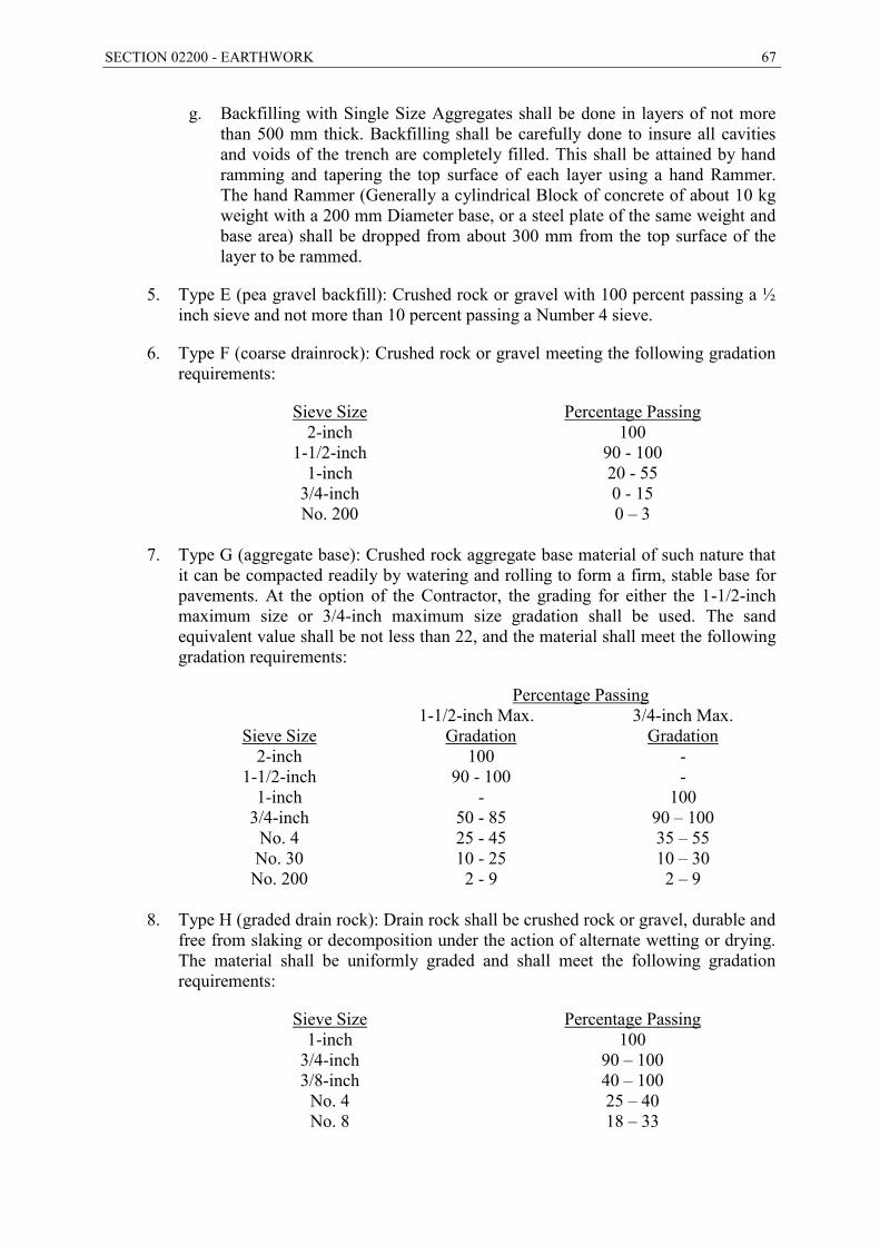
SECTION 02200 - EARTHWORK 67
g. Backfilling with Single Size Aggregates shall be done in layers of not more than 500 mm thick. Backfilling shall be carefully done to insure all cavities and voids of the trench are completely filled. This shall be attained by hand ramming and tapering the top surface of each layer using a hand Rammer. The hand Rammer (Generally a cylindrical Block of concrete of about 10 kg weight with a 200 mm Diameter base, or a steel plate of the same weight and base area) shall be dropped from about 300 mm from the top surface of the layer to be rammed.
5. Type E (pea gravel backfill): Crushed rock or gravel with 100 percent passing a ½ inch sieve and not more than 10 percent passing a Number 4 sieve.
6. Type F (coarse drainrock): Crushed rock or gravel meeting the following gradation requirements:
Sieve Size Percentage Passing 2-inch 100
1-1/2-inch 90 - 100 1-inch 20 - 55
3/4-inch 0 - 15 No. 200 0 – 3
7. Type G (aggregate base): Crushed rock aggregate base material of such nature that
it can be compacted readily by watering and rolling to form a firm, stable base for pavements. At the option of the Contractor, the grading for either the 1-1/2-inch maximum size or 3/4-inch maximum size gradation shall be used. The sand equivalent value shall be not less than 22, and the material shall meet the following gradation requirements:
Percentage Passing 1-1/2-inch Max. 3/4-inch Max.
Sieve Size Gradation Gradation 2-inch 100 -
1-1/2-inch 90 - 100 - 1-inch - 100
3/4-inch 50 - 85 90 – 100 No. 4 25 - 45 35 – 55 No. 30 10 - 25 10 – 30 No. 200 2 - 9 2 – 9
8. Type H (graded drain rock): Drain rock shall be crushed rock or gravel, durable and
free from slaking or decomposition under the action of alternate wetting or drying. The material shall be uniformly graded and shall meet the following gradation requirements:
Sieve Size Percentage Passing 1-inch 100
3/4-inch 90 – 100 3/8-inch 40 – 100
No. 4 25 – 40 No. 8 18 – 33

68 SECTION 02200 - EARTHWORK
No. 30 5 – 15 No. 50 0 – 7 No. 200 0 – 3
a. The drainrock shall have a sand equivalent value not less than 75. The finish
graded surface of the drainrock immediately beneath hydraulic structures shall be stabilized to provide a firm, smooth surface upon which to construct reinforced concrete floor slabs. The Contractor shall use, at its option, one of the asphalt types listed below:
Type 1 Type 2 Type 3 Designation SC-800 SC-250 RS-1 Spray Temperature (oF) 175-255 165-200 70-120 Coverage (gal/sq yd) 0.50 0.50 0.50
b. If the surface remains tacky, sufficient sand shall be applied to absorb the excess asphalt.
9. Type I: Not used.
10. Type J (cement-treated backfill): Material which consists of Type H material, or any mixture of Types B, C, G, and H materials which has been cement-treated so that the cement content of the material is not less than 5 percent by weight when tested in accordance with ASTM D 2901 or equivalent- Standard Test Method for Cement Content of Freshly Mixed Soil Cement. The ultimate compressive strength at 28 days shall be not less than 400 psi when tested in accordance with ASTM D 1633 or equivalent - Standard Test Method for Compressive Strength of Molded Soil - Cement Cylinders.
11. Type K (topsoil): Stockpiled topsoil material which has been obtained at the site by removing soil to a depth not exceeding 65 cm. Removal of the topsoil shall be done after the area has been stripped of vegetation and debris.
12. Type L (controlled low strength material): Not used.
13. Type M (aggregate subbase): Crushed rock aggregate subbase material that can be compacted readily by watering and rolling to form a firm stable base. The sand equivalent value shall be not less than 18 and the material shall meet the following gradation requirements:
Sieve Size Percentage Passing 3-inch 100
2-1/2 inch 87 – 100 No. 4 35 – 95
No. 200 0 – 29
14. Type N (trench plug): Low permeable fill material, a non-dispersible clay material having a minimum plasticity index of 10.
15. Type O (Approved Selected Material): From 300 mm above the top of the pipe to the finished ground level, the trench shall be backfilled with approved selected
SECTION 02200 - EARTHWORK 69
material, consolidated by approved mechanical methods in layers with a thickness not more than 150mm thick.
F. Each layer to be compacted separately. The degree of compaction shall not be less than 95% of maximum dry density according to standard proctor density or modified proctor density.
G. If necessary and to ensure proper compaction, the material shall first be wet by sprinkling, a safe amount of water shall be available at the site when backfilling.
H. The approved selected material to be used for backfilling the trenches shall be suitable and approved excavated material, free from debris or other contamination, shall be suitably graded to obtain the required compaction and shall not contain stones, rock, or concrete fragments larger than 50mm in any dimension. Suitable fill material shall have a plasticity index of less than 10, as determined in accordance with B.S 1377 and shall have a maximum dry density greater than 1.6g/cm3 according to modified proctor density.
I. The backfilling material shall be deposited and compacted uniformly in layers of 150mm compacted thicknesses. The Contractor shall provide adequate number of power tampers and other compaction equipment and each compaction layer shall be compacted to not less than 95% of maximum dry density.
J. In the event that filled material is too wet, either due to rain or to excessive watering or any other reasons, no compaction shall be carried out until the previous and newly placed materials have dried out sufficiently to permit proper compaction. Other precaution shall be taken as may be necessary and directed to obtain the percentages of compaction specified.
K. In the event that excavated material is insufficient or unsuitable for the backfilling and filling operations on site, the Contractor shall obtain suitable fill materials from approved borrow pits.
L. If pipes are laid in agricultural land, then the top two layers of backfill shall be filled with the agricultural soil originally found at the top before excavation.
M. A land is considered agricultural only if it is outside the residential area and the land use is specified on the zoning map and the line is not laid in a place where a road, street, or highway will be constructed in future.
N. Materials used to backfill around manholes should meet the specifications set for the materials used to backfill the trench. But in roads of width greater than 3m, the material around manholes should be selected and compacted.
2.2 UNSUITABLE MATERIAL
A. Unsuitable materials include the materials listed below.
1. Soils which, when classified under ASTM D 2487 - Standard Classification of Soils for Engineering Purposes (Unified Soil Classification System), fall in the classifications of Pt, OH, CH, MH, or OL.
70 SECTION 02200 - EARTHWORK
2. Soils which cannot be compacted sufficiently to achieve the density specified for the intended use.
3. Materials that contain hazardous or designated waste materials including petroleum hydrocarbons, pesticides, heavy metals, and any material which may be classified as hazardous or toxic according to applicable regulations.
4. Soils that contain greater concentrations of chloride or sulfate ions, or have a soil resistivity or pH less than the existing on-site soils.
5. Topsoil, except as allowed below.
2.3 USE OF FILL, BACKFILL, AND EMBANKMENT MATERIAL TYPES
A. The Contractor shall use the types of materials as designated herein for all required fill, backfill, and embankment construction hereunder.
B. Where these Specifications conflict with the requirements of any local agency having jurisdiction or with the requirements of a pipe material manufacturer, the Engineer shall be immediately notified. In case of conflict between types of pipe embedment backfills, the Contractor shall use the agency-specified backfill material if that material provides a greater degree of structural support to the pipe, as determined by the Engineer. In case of conflict between types of trench or final backfill types, the Contractor shall use the agency-specified backfill material if that material provides the greater in-place density after compaction.
C. Fill and backfill types shall be used in accordance with the following provisions:
1. Pipe zone backfill, as defined under "Pipe and Utility Trench Backfill" below, shall consist of the following materials for each pipe material listed below.
a. Mortar coated pipe, concrete pipe, and un-coated ductile iron pipe shall be provided Type A or B pipe bedding and embedment backfill material.
b. Coal tar enamel coated pipe, polyethylene encased pipe, tape wrapped pipe, and other non-mortar coated pipe shall be backfilled with Type C bedding and embedment zone backfill material.
c. Plastic pipe and vitrified clay pipe shall be backfilled with Type D bedding and embedment zone backfill material. Vitrified clay pipe shall be backfilled with Type B material to the top of the pipe zone.
d. Where pipelines are installed on grades exceeding 4 percent, and where backfill materials are graded such that there is less than 10 percent passing a Number 4 sieve, trench plugs of Type J, L, or N material shall be provided at maximum intervals of 200 feet unless indicated otherwise.
2. Trench zone backfill for pipelines as defined under "Pipe and Utility Trench Backfill" shall be backfilled with Type O material (Approved Selected Material), in accordance with drawings and Engineer approval.
SECTION 02200 - EARTHWORK 71
3. Final backfill material for pipelines under paved areas, as defined under "Pipe and Utility Trench Backfill" shall be Type G (aggregate base) backfill material. Final backfill under areas not paved shall be the same material as that used for trench backfill.
4. Backfill used to replace pipeline trench over-excavation shall be a layer of Type F material with a 6-inch top filter layer of Type E material or filter fabric to prevent migration of fines for wet trench conditions or the same material as used for the pipe zone backfill if the trench conditions are not wet.
2.4 MATERIALS TESTING
A. All soils testing of samples submitted by the Contractor will be done by a testing laboratory approved by the Employer and at the Contractor’s expense. At its discretion, the Engineer may request that the Contractor supply samples for testing of any material used in the work.
B. Particle size analysis of soils and aggregates will be performed using ASTM D 422 - Standard Test Method for Particle-Size Analysis of Soils.
C. Determination of sand equivalent value will be performed using ASTM D 2419 - Standard Test Method for Sand Equivalent Value of Soils and Fine Aggregate.
D. Unified Soil Classification System: References in this Section to soil classification types and standards shall have the meanings and definitions indicated in ASTM D 2487. The Contractor shall be bound by all applicable provisions of said ASTM D 2487 in the interpretation of soil classifications.
PART 3 -- EXECUTION
3.1 EXCAVATION - GENERAL
A. General: Except when specifically provided to the contrary, excavation shall include the removal of all materials of whatever nature encountered, including all obstructions of any nature that would interfere with the proper execution and completion of the WORK. The removal of said materials shall conform to the lines and grades indicated or ordered. Unless otherwise indicated, the entire construction site shall be stripped of all vegetation and debris, and such material shall be removed from the site prior to performing any excavation or placing any fill. The Contractor shall furnish, place, and maintain all supports and shoring that may be required for the sides of the excavations. Excavations shall be sloped or otherwise supported in a safe manner in accordance with applicable State safety requirements.
B. Removal and Exclusion of Water: The Contractor shall remove and exclude water, including stormwater, groundwater, irrigation water, and wastewater, from all excavations. Dewatering wells, well points, sump pumps, or other means shall be used to remove water and continuously maintain groundwater at a level at least 600 mm below the bottom of excavations before the excavation work begins at each location. Water shall be removed and excluded until backfilling is complete and all field soils testing have been completed.
72 SECTION 02200 - EARTHWORK
C. Notification of Engineer: The Contractor shall notify the Engineer at least 3 days in advance of completion of any structure excavation and shall allow the Engineer a review period of at least one day before the exposed foundation is scarified and compacted or is covered with backfill or with any construction materials.
3.2 PIPELINE AND UTILITY TRENCH EXCAVATION
A. General: Unless otherwise indicated or ordered, excavation for pipelines and utilities shall be an open-cut trench with widths as indicated.
B. Trench Bottom: Except when pipe bedding is required, the bottom of the trench shall be excavated uniformly to the grade of the bottom of the pipe bedding
C. Open Trench: The maximum amount of open trench permitted in any one location shall be 150 m, or the length necessary to accommodate the amount of pipe installed in a single day, whichever is greater. All trenches shall be fully backfilled at the end of each day or, in lieu thereof, shall be covered by heavy steel plates adequately braced and capable of supporting vehicular traffic in those locations where it is impractical to backfill at the end of each day. The above requirements for backfilling or use of steel plate will be waived in cases where the trench is located further than 30 m from any traveled roadway or occupied structure. In such cases, however, barricades and warning lights meeting safety requirements shall be provided and maintained.
D. Trench Over-Excavation: Where trenches are indicated to be over-excavated, excavation shall be to the depth indicated, and backfill shall be installed to the grade of the bottom of the pipe bedding.
E. Over-Excavation: When ordered by the Engineer, whether indicated on the Drawings or not, trenches shall be over-excavated beyond the depth and/or width shown. Such over-excavation shall be to the dimensions ordered. The trench shall then be backfilled to the grade of the bottom of the pipe bedding. Over-excavation less than 150 mm below the limits on the Drawings shall be done at no increase in cost to the Employer. When the over-excavation ordered by the Engineer is 150 mm or greater below the limits shown, or wider, additional payment will be made to the Contractor. Said additional payment will be made under separate unit price bid items for over-excavation if such bid items have been established; otherwise payment will be made in accordance with a negotiated price.
F. If a moveable trench shield is used during excavation operations, the trench width shall be wider than the shield so that the shield is free to be lifted and then moved horizontally without binding against the trench sidewalls. If the trench walls cave in or slough, the trench shall be excavated as an open excavation with sloped sidewalls or with trench shoring, as indicated and as required by the pipe structural design.
3.3 OVER-EXCAVATION NOT ORDERED OR INDICATED
A. Any over-excavation carried below the grade ordered or indicated, shall be backfilled and compacted to the required grade with the indicated material.
SECTION 02200 - EARTHWORK 73
3.4 EXCAVATION IN LAWN AREAS
A. Where excavation occurs in lawn areas, the sod shall be carefully removed, dampened, and stockpiled to preserve it for replacement. Excavated material may be placed on the lawn; provided, that a drop cloth or other suitable method is employed to protect the lawn from damage. The lawn shall not remain covered for more than 72 hours. Immediately after completion of backfilling and testing of the pipeline, the sod shall be replaced and lightly rolled in a manner so as to restore the lawn as near as possible to its original condition. Contractor shall provide new sod if stockpiled sod has not been replaced within 72 hours.
3.5 EXCAVATION IN VICINITY OF TREES
A. Except where trees are indicated to be removed, trees shall be protected from injury during construction operations. No tree roots over 50 mm in diameter shall be cut without express permission of the Engineer. Trees shall be supported during excavation by any means previously reviewed by the Engineer.
3.6 ROCK EXCAVATION
A. Rock excavation shall include removal and disposal of the following: (1) all boulders measuring 0.25 m3 or more in volume; (2) all rock material in ledges, bedding deposits, and un-stratified masses which cannot be removed without systematic drilling and blasting; (3) concrete or masonry structures which have been abandoned; and (4) conglomerate deposits which are so firmly cemented that they possess the characteristics of solid rock and which cannot be removed without systematic drilling and blasting.
B. Explosives and Blasting will not be permitted.
3.7 DISPOSAL OF EXCESS EXCAVATED MATERIAL
A. The Contractor shall remove and dispose of all excess excavated material at a site selected by the Contractor and approved by the Engineer.
3.8 BACKFILL - GENERAL
A. Backfill shall not be dropped directly upon the pipes.
B. Except for drainrock materials being placed in over-excavated areas or trenches, backfill shall be placed after all water is removed from the excavation, and the trench sidewalls and bottom have been dried to a moisture content suitable for compaction.
C. If a moveable trench shield is used during excavation, pipe installation, and backfill operations, the shield shall be moved by lifting the shield free of the trench bottom or backfill and then moving the shield horizontally, The Contractor shall not drag trench shields along the trench causing damage or displacement to the trench sidewalls, the pipe, or the bedding and backfill.
D. Immediately prior to placement of backfill materials, the bottoms and sidewalls of trenches shall have all loose sloughing, or caving soil and rock materials removed.
74 SECTION 02200 - EARTHWORK
Trench sidewalls shall consist of excavated surfaces that are in a relatively undisturbed condition before placement of backfill materials.
3.9 PLACING AND SPREADING OF BACKFILL MATERIALS
A. Backfill materials shall be placed and spread evenly in layers. When compaction is achieved using mechanical equipment, the layers shall be evenly spread so that when compacted each layer shall not exceed 150 mm in thickness.
B. When compaction is achieved using flooding and jetting methods, each layer shall not exceed 900 mm in thickness after compaction.
C. During spreading, each layer shall be thoroughly mixed as necessary to promote uniformity of material in each layer. Pipe zone backfill materials shall be manually spread around the pipe so that when compacted the pipe zone backfill will provide uniform bearing and side support.
D. Where the backfill material moisture content is below the optimum moisture content, water shall be added before or during spreading until the proper moisture content is achieved.
E. Where the backfill material moisture content is too high to permit the specified degree of compaction the material shall be dried until the moisture content is satisfactory.
3.10 COMPACTION OF FILL AND BACKFILL
A. Each layer of Types A, B, C, G, H, and K backfill materials as defined herein, where the material is graded such that at least 10 percent passes a No. 4 sieve, shall be mechanically compacted to the indicated percentage of density. Equipment that is consistently capable of achieving the required degree of compaction shall be used and each layer shall be compacted over its entire area while the material is at the required moisture content.
B. Each layer of Type E, F, and J backfill materials shall be compacted by means of at least 2 passes from a flat plate vibratory compactor. When such materials are used for pipe zone backfill, vibratory compaction shall be used at the top of the pipe zone or at vertical intervals of 600 mm, whichever is the least distance from the subgrade.
C. Pipe zone backfill materials that are granular, may be compacted by a combination of flooding and vibration by jetting, when acceptable to the Engineer.
D. Pipeline trench zone backfill materials, containing 5 percent or less of material passing a No. 200 sieve, may be compacted using flooding and jetting or vibration if the Contractor uses effective procedures that yield the specified compaction test results. Flooding and jetting shall not be done in such a manner that the pipe or nearby utilities are damaged, in areas of poorly draining or expansive soils, or where the use of the procedure is prohibited by any agency having jurisdiction over the street or right-of-way. Approved jet pipes or immersible vibrators shall be used so that each backfill layer is saturated and consolidated to its full depth before the next layer is placed. Jet pipes shall be kept at least 150 mm away from the pipe where the backfill is being consolidated and 600 mm away from other pipes or utilities.
SECTION 02200 - EARTHWORK 75
E. Equipment weighing more than 4,500 kg shall not be used closer to walls than a horizontal distance equal to the depth of the fill at that time. Hand operated power compaction equipment shall be used where use of heavier equipment is impractical or restricted due to weight limitations.
F. Backfill around and over pipelines that is mechanically compacted shall be compacted using light, hand operated, vibratory compactors and rollers. After completion of at least two feet of compacted backfill over the top of pipeline, compaction equipment weighing no more than 3,500 kg may be used to complete the trench backfill.
G. Compaction Requirements: The following compaction test requirements shall be in accordance with ASTM D 1557 - Test Method for Laboratory Compaction Characteristics of Soils Using Modified Effort (56,000 ft - lbf/ft3) (2,700 kN-m/m3) for Type A, B, C, G, H, I, K, M, and N materials and in accordance with ASTM D 4253 - Standard Test Method for Maximum Index Density and Unit Weight of Soils Using a Vibratory Table, and D 4254 - Standard Test Method for Minimum Index Density and Unit Weight of Soils and Calculation of Relative Density, for Type B, E, F, and J materials. Where agency or utility company requirements govern, the highest compaction standards shall apply.
Location or Use of Fill Percentage of
Maximum Density
Percentage of RelativeDensity
Pipe embedment backfill for flexible pipe. 95 70 Pipe bedding and over-excavated zones under bedding for flexible pipe, including trench plugs.
95 70
Pipe embedment backfill for rigid pipe 90 55 Pipe zone backfill portion above embedment for rigid pipe. 90 70
Pipe bedding and over-excavated zones under bedding for rigid pipe. 90 70
Topsoil (Type K material) 80 N.A. Aggregate base or subbase (Type G or M material) 95 N.A.
3.11 PIPE AND UTILITY TRENCH BACKFILL
A. Pipe Zone Backfill
1. The pipe zone is defined as that portion of the vertical trench cross-section lying between a plane below the bottom surface of the pipe and a plane at a point above the top surface of the pipe as indicated. The bedding is defined as that portion of pipe zone backfill material between the trench subgrade and the bottom of the pipe. The embedment is defined as that portion of the pipe zone backfill material between the bedding and a level line as indicated.
76 SECTION 02200 - EARTHWORK
2. After compacting the bedding the Contractor shall perform a final trim using a stringline for establishing grade, such that each pipe section when first laid will be continually in contact with the bedding along the extreme bottom of the pipe.
3. The pipe zone shall be backfilled with the indicated backfill material. The Contractor shall exercise care to prevent damage to the pipeline coating, cathodic bonds, and the pipe itself during the installation and backfill operations.
4. If a moveable trench shield is used during backfill operations the shield shall be lifted to a location above each layer of backfill material prior to compaction of the layer. The Contractor shall not displace the pipe or backfill while the shield is being moved.
B. Trench Zone Backfill: After the pipe zone backfills have been placed, backfilling of the trench zone may proceed. The trench zone is defined as that portion of the vertical trench cross-section lying as indicated between a plane above the top surface of the pipe and a plane at a point 450 mm below the finished surface grade, or if the trench is under pavement, 450 mm below the roadway subgrade. If flooding, ponding, or jetting is used the pipe shall be filled with water to prevent flotation.
C. Final Backfill: Final backfill is all backfill in the trench cross-sectional area within 300 mm of finished grade, or if the trench is under pavement, all backfill within 300 mm of the roadway subgrade.
3.12 FILL
A. The area where a fill is to be constructed shall be cleared of all vegetation, roots and foreign material. Following this, the surface shall be moistened, scarified to a depth of 150 mm, and rolled or otherwise mechanically compacted. fill material shall be placed and spread evenly in approximately horizontal layers. Each layer shall be moistened or aerated, as necessary. Unless otherwise approved by the Engineer, each layer shall not exceed 150 mm of compacted thickness. The fill shall be compacted to 95 percent of maximum density under paved areas, and 90 percent of maximum density elsewhere.
3.13 FIELD TESTING
A. General: All field soils testing will be done by a testing laboratory approved by the Employer at the Contractor’s expense.
B. Where soil material is required to be compacted to a percentage of maximum density, the maximum density at optimum moisture content will be determined in accordance with Method C of ASTM D 1557. Where cohesionless, free draining soil material is required to be compacted to a percentage of relative density, the calculation of relative density will be determined in accordance with ASTM D 4253 and D 4254. Field density in-place tests will be performed in accordance with ASTM D 1556 - Standard Test Method for Density and Unit Weight of Soil in Place by the Sand-Cone Method, ASTM D 2922 - Standard Test Methods for Density of Soil and Soil-Aggregate in Place By Nuclear Methods (Shallow Depth), or by such other means acceptable to the Engineer.
C. In case the test of the fill or backfill show non-compliance with the required density, the Contractor shall accomplish such remedy as may be required to insure compliance.
SECTION 02200 - EARTHWORK 77
D. The Contractor shall provide test trenches and excavations including excavation, trench support, and groundwater removal for field soils testing operations. The trenches and excavations shall be provided at the locations and to the depths required by the Employer.
E. Compaction tests in pipeline trenches shall be made every 10 meters, of the pipe zone and of the completed backfill.
- END OF SECTION –
78 SECTION 02441 - PIPELINE CONSTRUCTION BY TRENCHLESS METHODS
SECTION 02441 - PIPELINE CONSTRUCTION BY TRENCHLESS METHODS
PART 1 -- GENERAL
1.1 GENERAL
A. The work covered in this section is for pipe laying works by trenchless technology namely Pipe Jacking method for crossing of the Major Roads/ National Highways. The work includes for all labour, equipment and materials in order to complete all required piping, earthwork, concrete work, and related civil work as described in the Specifications and Drawings.
1.2 PIPE JACKING
A. Pipe jacking is a trenchless technology method for installing a prefabricated pipe through the ground from a driving shaft to a reception shaft. In the pipe jacking operation, jacks located in the drive shaft propel the pipes. The jacking force is transmitted through the pipe-to-pipe interaction, to the excavating face. When the excavation is accomplished, the spoil is transported through the jacking pipe in the drive shaft by manual or technical means. Both excavation and spoil removal processes are being done manually from inside the pipe during the jacking operation.
1.3 CASING PIPE DETAILS
A. The locations of trenchless crossing are shown in the drawings. The technical specification of the Casing pipe shall be as per AS/NZS 4058, BS 5911-1, JSWAS A-2 or other equivalent standards approved by the Engineer for the following requirements.
1. Crossing No. 1 at nearby point(Easting: 231785, Northing: 215119)
Pipe Jacking. Length : 30 m Material : Reinforced Concrete Pipe Nominal Bore : DN1,000
2. Crossing No. 2 at nearby point (Easting: 231990, Northing: 214508)
Pipe Jacking. Length : 30 m Material : Reinforced Concrete Pipe Nominal Bore : DN1,000
3. Crossing No. 3 at nearby point (Easting: 232196, Northing: 213647)
Pipe Jacking. Length : 30 m Material : Reinforced Concrete Pipe Nominal Bore : DN1,000
1.4 SCOPE OF WORKS
A. The Scope of works generally envisaged under Trenchless tender include but not limited to the following:

SECTION 02441 - PIPELINE CONSTRUCTION BY TRENCHLESS METHODS 79
1. Interpretation and verification of all data in respect of hydrogeological and geotechnical surveys, furnished by the owner. Carrying out all additional surveys required for connecting data related to design and construction of the crossings.
2. Design and Engineering of crossing to meet the technical parameters of the Crossing and specifications.
3. Performing all engineering and design calculations to verify suitability of pipe thickness proposed for installation in accordance with requirements of application codes/ standard for Engineer’s review and approval.
4. Preparation of all detailed construction/Installation drawings and methodology for trenchless and submission for Engineer’s approval.
5. Submission of Quality Assurance (QA) and Quality Control (QC) Procedure for Engineer’s approval.
6. Procurement and inspection of all materials and consumables required for or in connection with execution of the crossing.
7. Mobilizing equipment, manpower and other resources etc, site preparation including arranging of additional land required for pipeline/fabrication, stringing, placement of equipment and preparation of pipeline connecting area and access to work site.
8. Setting out works including establishing the location of extremity points (i.e. entry and exit locations of jacking portion of the pipeline to be laid by trenchless techniques, etc.) on ground including carrying out of pre-construction survey and collection of all necessary data.
9. Preparation of pipe string, installation of the carrier pipe at the designated crossing location prepared by single trenchless operation to the correct profile as per the drawing approved by the Engineer.
10. Disposal of fluid returns, cutting produced, and debris from drilling/jacking operation from worksite including arranging disposal site at contractors cost and initiative.
11. Submission of daily log activities with all relevant details connected with trenchless operations for installing pipeline as required by the Engineer.
12. Final clean up & restoration of the right of way including de-mobilization
13. Submission of as-built drawings.
14. All other works, which are not specifically indicated above, but required for successful completion of the trenchless work, associated mainline work and allied works as per the tender documents, drawings, construction methodology & details engineering calculation etc.

80 SECTION 02441 - PIPELINE CONSTRUCTION BY TRENCHLESS METHODS
1.5 CONTRACTOR’S GENERAL REQUIREMENTS
A. The contractor shall familiarize himself with the site conditions and technical requirement. CPM chart of the entire Trenchless work shall be prepared in sufficient details and shall be got approved from the Engineer before start of Work. Permission shall be obtained by the Employer from authorities holding right of way.
B. The contractor shall work out following design requirements before start of Trenchless work:
1. Equipment Requirement
2. Consumables including handling and operational details.
3. Project layouts including sizes, location and depth of entry and exit pits
4. Crossing length and depth requirements including bending radius of product pipe line if required as per project requirements.
5. Horizontal and Vertical Clearance
C. The contractor shall carry out Trenchless work ensuring public safety, protecting existing underground utilities and structures on ground at site.
D. The entire Trenchless equipment shall be operated by contractor strictly as per manufacturer’s operation manual and a copy of same shall be provided to the Engineer by contractor.
E. All underground utilities shall be indentified and mapped and shall be submitted before start of work. The mapping shall include both horizontal as well as vertical position of underground utility and structures/ obstructions.
F. The Trenchless Contractor shall mark the entry and exit locations and proposed alignment at 10 metre interval and shall got it approved from the Engineer before start of work.
G. Necessary Traffic control plan shall be made by Contractor and necessary approval of Civil Authorities/Traffic police as applicable shall be taken and the contractor shall deploy necessary manpower for traffic control as required by competent authorities.
H. The contractor shall handle and dispose of all construction waste as per directions of the Engineer and it will be ensured that drilling fluid / excavated solids do not enter roadways, drains and sewer lines. Drilling fluid shall be disposed of in environmentally safe manner as per govt. regulations.
I. Back filling operations shall not begin until written unless the entire work has been inspected and passed by the Engineer
J. The contractor shall clean the site on completion of Trenchless work and shall ensure that no heaving or humping of ground has occurred.
SECTION 02441 - PIPELINE CONSTRUCTION BY TRENCHLESS METHODS 81
PART 2 -- EXECUTION
1.6 INSTALLATION WORKS
A. LINE AND GRADE: Install pipe at line and grade that will allow the carrier pipe to be installed at its true starting elevation and grade within the specified maximum alignment deviation of the pipe centerline.
B. CASING PIPE INSTALLATION:
1. Install pipe by approved methods.
2. Use a jacking collar, timbers, and other means as necessary to protect the driven end of the pipe from damage.
3. Do not exceed the compressive or tensile strength capacity of the pipe during pushing or pulling operations.
4. Fully support bore hole at all times to prevent collapse. Insert pipe as soil is removed, or support bore with drilling fluid.
5. Fully weld all casing pipe joints. Use an interlocking connection system when approved by the Engineer.
6. Fill space between the inside of the bore hole and the outside of the pipe with special fill material if the space is greater than 1 inch.
C. CARRIER PIPE INSTALLATION THROUGH CASING:
1. Clean dirt and debris from the interior of the casing pipe after installation.
2. Install casing spacers on carrier pipe sections as necessary to support the pipe barrel according to the pipe manufacturer's recommendations
3. Ensure that thrust loads will not damage carrier pipe joints. Provide thrust collars between joint shoulders of concrete pipe.
4. Provide timbers for sufficient cushioning between the end of the pipe pushed and the jacking equipment to prevent damage to the pipe. Do not allow the steel jack face to thrust against the unprotected pipe end.
5. Position jacks so the resulting force is applied evenly to the entire end of the pipe.
6. Assemble pipe joints in the jacking pit before pushing the carrier pipe into the casing.
7. Close the end of the casing pipe around the carrier pipe with a casing end seal.
8. When specified in the contract documents, fill the annular space between the carrier and casing pipe with flowable mortar or CLSM.
- END OF SECTION –
82 SECTION 02460 - A.C. PAVEMENT AND BASE
SECTION 02460 - A.C. PAVEMENT AND BASE
PART 1 -- GENERAL
1.1 THE REQUIREMENT
A. The Contractor shall provide A.C. pavement and base, complete and in place, in accordance with the Contract Documents.
B. The Contractor shall provide Asphalt Concrete (AC) pavement and base, complete and in place, in accordance with the contract documents. The Contractor shall also abide with the Ministry of Public Works and Housing Circular No. (26726/5) dated 7/9/2008 regarding MPWH services within roads and all related costs shall be included in the contract price.
1.2 REFERENCE SPECIFICATIONS, CODES, AND STANDARDS
AASHTO M 82 Cut-Back Asphalt (Medium Curing Type)
AASHTO M 140 Emulsified Asphalt
AASHTO M 208 Cationic Emulsified Asphalt
AASHTO M 226 Viscosity Graded Asphalt Cement
ASTM C 117 Extracted Aggregate Gradation
ASTM C 136 Extracted Aggregate Gradation
ASTM D 242 Mineral Filler for Bituminous Paving Mixtures
ASTM D 421 Practice for Dry preparation of soil samples for particle size analysis and determination of soil constants.
ASTM D 692 Coarse Aggregate for Bituminous Paving Mixtures
ASTM D 977 Emulsified Asphalt
ASTM D 979 An asphalt concrete sample
ASTM D 1073 Fine Aggregate for Bituminous Paving Mixtures
ASTM D 1188 Bulk Specific Gravity and Density of Compacted Bituminous Mixtures Using Paraffin-Coated Specimens.
ASTM D 1241 Specification for materials for Soil Aggregate Subbase, base, and surface courses.
ASTM D 1557 Moisture-Density Relations of Soils and Soil - Aggregate Mixtures Using 10-lb (4.54-kg) Rammer and 18-in (45-mm) Drop7
SECTION 02460 - A.C. PAVEMENT AND BASE 83
ASTM D 1559 Test Method for Resistance to Plastic flow of Bituminous Mixtures using Marshal Apparatus
ASTM D 1883 Determination of the CBR of pavement subgrade, sub base, and base/course materials
ASTM D 2172 Asphalt Content
ASTM D 2027 Cutback Asphalt (Medium Curing Type)
ASTM D 2041 Maximum Theoretical Density
ASTM D 2397 Cationic Emulsified Asphalt
ASTM D 2419 Test method for Sand Equivalent Value of Soils and Fine Aggregate.
ASTM D 2726 Bulk Specific Gravity and Density of Compacted Bituminous Mixtures using Saturated Surface-Dry Specimens.
ASTM D 2844 Test Method for Resistance R-Value and Expansion Pressure of Compacted Soils
ASTM D 2950 Inplace Compaction test.
ASTM D 2922 Test Methods for Density of Soil and soil-Aggregate in Place by Nuclear Method (Shallow Depth)
ASTM D 317 Test Methods for Moisture Content of Soil and soil-Aggregate in Place by Nuclear Method (Shallow Depth)
ASTM D 3203 Air voids in Asphalt concrete
ASTM D 3515 Hot-Mixed, Hot-Laid Bituminous Paving Mixtures.
ASTM D 3744 Test Method for Aggregate Durability Index.
1.3 CONTRACTOR SUBMITTALS
A. Submittals shall be in accordance with Section 01300 - Contractor Submittals. Include materials testing reports, job-mix formulas, and other pertinent information satisfactory to the Engineer.
B. Suitability Tests of Proposed Materials: Tests for conformance with the Specifications shall be performed prior to start of the WORK. The samples shall be identified to show the name of the material, aggregate source, name of the supplier, contract number, and the segment of the WORK where the material represented by the sample is to be used. Results of all tests shall be submitted to the Engineer for approval. Materials to be tested shall include aggregate base, coarse and fine aggregate for paving mixtures, mineral filler, and asphalt cement.
84 SECTION 02460 - A.C. PAVEMENT AND BASE
C. Trial Batch: Before placing any paving material, a testing laboratory acceptable to the Engineer shall prepare a trial batch of asphalt concrete for each job-mix formula to be used by the Contractor for the work. The trial batch shall be prepared using the aggregates and asphalt cement proposed by the Contractor, and approved by the Engineer. The compacted trial batch shall provide a basis for computing the voids ratio, provide an indication of the optimum asphalt content, and establish a basis for controlling compaction during construction.
PART 2 -- PRODUCTS
2.1 AGGREGATE BASE COURSE
A. Materials for aggregate base shall be Type G material in accordance with Section 02200 -Earthwork.
B. PRIME COAT
C. Prime coat shall be Grade SC-250 liquid asphalt complying with the requirements of AASHTO M 82 (ASTM D 2027). Grade SC-70 liquid asphalt may be used when acceptable to the Engineer.
2.2 TACK COAT
A. Tack coat shall be emulsified asphalt Grade SS-1 or SS-1h, CSS-1 or CSS-1h diluted with one part water to one part emulsified asphalt, undiluted asphalt Grade RS-1 or CRS-1, or paving asphalt Grade AR-1000. Emulsified asphalt shall comply with the requirements of AASHTO M 140 (ASTM D 977) or M 208 (ASTM D 2397); paving asphalt shall comply with the requirements of AASHTO M 226 (ASTM D 3381).
2.3 ASPHALT CEMENT
A. Asphalt Cement shall be Grade AR-16000 or AR-8000 complying with the requirements of AASHTO M226 (ASTM D 3381).
2.4 ASPHALT-AGGREGATE MIXTURE (BINDER COURSE)
A. Base Course Mixture: The Contractor shall submit for approval a job-mix formula for each mixture. The job-mix formula for the asphalt-aggregate base course mixture shall be within the following limits:
Sieve Size Total Percent Passing by Weight 2-inch --
1-1/2-inch 100 1-inch 90-100
3/4-inch -- 1/2-inch 56-80 3/8-inch --
No. 4 29-59 No. 8 19-45 No. 50 5-17 No. 200 1-7
Asphalt Content 3-9 percent by weight of total mix
SECTION 02460 - A.C. PAVEMENT AND BASE 85
B. Base Course Mixture Test Criteria: The asphalt-aggregate surface course mixture shall
meet the following test criteria:
1. Stability (Marshall): 3,336
2. Flow (Marshall Method): 8-18
3. Air Voids: 3-5 percent
4. Voids in Mineral Aggregate: 14 percent
C. Surface Course Mixture: The job-mix formula for the asphalt-aggregate surface course mixture shall be within the following limits:
Sieve Size Total Percent Passing by Weight 2-inch --
1-1/2-inch -- 1-inch --
3/4-inch 100 1/2-inch 90-100 3/8-inch --
No. 4 44-74 No. 8 28-58 No. 50 5-21 No. 200 2-10
Asphalt Content 4-11 percent by weight of total mix D. Surface Course Mixture Test Criteria: The asphalt-aggregate surface course mixture
shall meet the following text criteria:
1. Stability (Marshall): 3,336 Newton
2. Flow (Marshall Method): 8-18
3. Air Voids: 3-5 percent
4. Voids in Mineral Aggregate: 14 percent
E. Asphalt-Aggregate Mixture Tolerances: The following tolerances for the job-mix formula will be allowed per single test:
Passing Sieve Percent 1/2-inch and larger ±8 3/8-inch and No. 4 ±7
No. 8 ±6 No. 50 ±5 No. 200 ±3
Asphalt Content, Wt. percent by weight of total mixture ±0.5
86 SECTION 02460 - A.C. PAVEMENT AND BASE
F. Results of single extraction and sieve tests shall not be used as the sole basis for acceptance or rejection of the mixture. Any variation from the job-mix formula greater than the tolerances shown above shall be investigated and the conditions causing the variations corrected.
PART 3 -- EXECUTION
3.1 SUBGRADE PREPARATION
A. The subgrade shall be prepared in accordance with Section 02200 - Earthwork as applicable to roadways and embankments. The surface of the subgrade after compaction shall be hard, uniform, and smooth and true to grade and cross-section. Subgrade for pavement shall not vary more than 6 mm from the indicated grade and cross section. Subgrade for base material shall not vary more than 12 mm from the indicated grade and cross section.
B. Apply soil sterilant or chemical weed control agent in strict compliance with manufacturer's dosages and application instructions, and any applicable laws, ordinances or regulations governing the use of such chemicals.
3.2 AGGREGATE BASE COURSE
A. Aggregate base shall be provided where indicated to the thickness indicated. Imported aggregate bases shall be delivered to the Site as uniform mixtures and each layer shall be spread in one operation. Segregation shall be avoided and the base shall be free of pockets of coarse or fine material. Where the required thickness is 150 mm or less, the base materials may be spread and compacted in one layer. Where the required thickness is more than 150 mm; the base material shall be spread and compacted in two or more layers of approximately equal thickness, and the maximum compacted thickness of any one layer shall not exceed 150 mm. The relative compaction of each layer of aggregate base shall be not less than 95 percent of maximum density when measured in accordance with ASTM D 1557. The compacted surface of the finished aggregate shall be hard, uniform, smooth and at any point shall not vary more than 6 mm from the indicated grade or cross-section.
3.3 PRIME COAT
A. Prior to placing of pavement a prime coat of cutback asphalt shall be applied to the compacted base or subgrade at a rate between 0.4 and 1 liters/m2.
3.4 TACK COAT
A. A tack coat shall be applied to existing paved surfaces where new asphalt concrete is to be placed on existing pavement. It shall also be applied to the contact surfaces of all cold pavement joints, curbs, gutters, manholes and the like immediately before the adjoining asphalt pavement is placed. Care shall be taken to prevent the application of tack coat material to surfaces that will not be in contact with the new asphalt concrete pavement. Diluted emulsified asphalt shall be applied at the rate of 0.2 to 0.6 liters/ m2. Undiluted emulsified asphalt shall be applied at the rate of 0.1 to 0.3 liters/ m2. Paving asphalt shall be applied at the rate of approximately 0.2 liters/ m2.
SECTION 02460 - A.C. PAVEMENT AND BASE 87
3.5 ASPHALT AGGREGATE MIXTURE
A. At the time of delivery to the Site, the temperature of mixture shall not be lower than 127 degrees C or higher than 160 degrees C, the lower limit to be approached in warm weather and the higher in cold weather.
B. Asphalt aggregate shall not be placed when the atmospheric temperature is below 4.4 degrees C or during unsuitable weather.
C. The asphalt aggregate shall be evenly spread upon the subgrade or base to such a depth that, after rolling, it will be of the required cross section and grade of the course being constructed.
D. The depositing, distributing, and spreading of the asphalt aggregate mixture shall be accomplished in a single, continuous operation by means of a self-propelled mechanical spreading and finishing machine designed specially for that purpose. The machine shall be equipped with a screed or strike-off assembly capable of being accurately regulated and adjusted to distribute a layer of the material to a definite pre-determined thickness. When paving is of a size or in a location that use of a self-propelled machine is impractical, the Engineer may waive the self-propelled requirement.
E. Spreading, once commenced, shall be continued without interruption.
F. The mix shall be compacted immediately after placing. Initial rolling with a steel-wheeled tandem roller, steel three-wheeled roller, vibratory roller, or a pneumatic-tired roller shall follow the paver as closely as possible. If needed, intermediate rolling with a pneumatic-tired roller shall be done immediately behind the initial rolling. Final rolling shall eliminate marks from previous rolling. In areas too small for the roller, a vibrating plate compactor or a hand tamper shall be used to achieve thorough compaction. Complete compaction before mix temperature cools to 185deg F.
G. Upon completion the pavement shall be true to grade and cross-section. When a 10-ft straightedge is laid on the finished surface parallel to the center of the roadway, the surface shall not vary from the edge of the straightedge more than 3 mm except at intersections or changes of grade. In the transverse direction, the surface shall not vary from the edge of the straightedge more than 6 mm.
H. The relative density after compaction shall be 95 percent of the density obtained by using ASTM D 1188 or D 2726. A properly calibrated nuclear asphalt testing device shall be used for determining the field density of compacted asphalt aggregate, or slabs or cores may be laboratory tested in accordance with ASTM D 1188.
3.6 DOUBLE SEAL COAT SURFACE TREATMENT, DESCRIPTION
A. This work shall consider of a wearing surface composed of a bituminous prime followed by two (2) applications of bituminous seal coats with each seal coat receiving an application of cover material in accordance with the Specifications and in conformity with the lines shown on the drawings or established by the Engineer.
B. MATERIALS FOR DOUBLE SEAL COAT SURFACE TREATMENT
88 SECTION 02460 - A.C. PAVEMENT AND BASE
1. PRIME COAT: The prime coat shall be medium curing cut-back asphalt grade MC-70. The rate of application shall be between 1.00 to 1.75 litres per square metre as specified by the Engineer.
2. SEAL COAT: The seal coat shall be 85/100 as per ASTM D946 penetration grade bitumen. The bitumen may be cut back with up to 2% by weight of kerosene to improve adhesion to the stone. The characteristics of the bitumen are shown in the following table:
85 - 100 AS PER ASTM D946 PENETRATION GRADE BITUMEN TEST METHOD OF MIN. MAX. TESTING (ASTM) Penetration at 25 deg.C, 100 g, 5 sec, 0.1 mm. D-5 85 100 Flash Point, Cleveland Open Cup, deg.C D92 : 2001 : 2001 232 - Ductility at 25 deg. C, cm D-113 100 - Solubility in trichoro ethylene, % D-2042 99 - Thin film oven test 3.2mm, 163 deg.C 5 hour loss on heating, percent D-1754 1.0 Penetration of residue percent of original D-5 47 - Ductility of residue at 25 deg.C 5 cm/min cm D-113 75 -
3. COVER MATERIAL: Aggregate for cover material shall be screenings of crushed
stone which are clean, tough, durable and free from dirt and other objectionable matter. The percentages of wear shall not be more than thirty (30) as determined by ASTM C-131. When subjected to five (5) cycles of magnesium sulphate soundness testing, as determined by ASTM C-88, it shall have a weight loss not greater than ten (10) percent. Aggregate shall have a flakiness index of not more than 30 (BS 812 : Part 105: Section 105.1) and an elongation index of not more than 30 (BS812 : Part 105: Section 105.2 and ACV of 20% (BS 812 : 1990 P110). No less than sixty (60) percent by weight of crushed stone shall consist of crushed pieces having two or more faces produced by fracture when tested by DM standard test

SECTION 02460 - A.C. PAVEMENT AND BASE 89
method DMS 8 : 2001. Aggregate shall conform to the following gradations and shall be approved by the Engineer.
4. DOUBLE BITUMINOUS SURFACE TREATMENT:
3/4" 1/2" 3/8" 1/4" No.4 No.10 No.30 First Course
100 70-90 0-15 - 0-2 - - -
Second Course
- - 100 90-100 60-85 0-25 0-5 0-2
C. EQUIPMENT FOR DOUBLE SEAL COAT SURFACE TREATMENT
1. The equipment used by the Contractor shall include a power broom or a power blower, or both; a self propelled, pneumatic-tyred roller, or steel-wheeled tandem roller (4 to 8 tons) or both; self-propelled aggregate spreading equipment that can be adjusted to spread accurately the specified amount per square metre; a bitumen distributor and equipment for heating the asphaltic materials.
2. Other equipment may be used in addition to the specified equipment when approved or requested by the Engineer.
D. PREPERATION OF MATERIAL FOR DOUBLE SEAL COAT SURFACE
TREATMENT
1. HEATING OF BITUMINOUS MATERIALS shall be with equipment as specified. The use of any method or agitation or heating that introduces free steam or moisture into the bituminous material is prohibited. Materials heated to temperatures above twenty eight (28) degrees C higher than the maximum application temperature specified shall be considered as overheated and shall be rejected until the material can be resampled and retested. The reacceptance or final rejection will be made by the Engineer on the same requirements under which the material was originally tested.
2. If aggregates are deemed by the Engineer to be dusty or dirty they shall be washed after which their use shall not be permitted until all free water has evaporated or been drained.
E. APPLICATION OF DOUBLE SEAL COAT SURFACE TREATMENT
1. After the prime coat has been applied and has thoroughly penetrated the surface and cured as specified, the Contractor shall apply 85/100 penetration bitumen and shall apply the cover material and roll and manipulate the surface, all in accordance with the requirements specified hereinafter. The material shall be uniformly applied at the rate designated to the surface being sealed.
2. Bituminous material shall be applied by means of a pressure distributor in a uniform, continuous speed over the section to be treated and within the temperature
90 SECTION 02460 - A.C. PAVEMENT AND BASE
range specified. The quantity of bituminous material to be used per square metre shall be within the limits hereinafter specified and as directed by the Engineer.
3. A strip of building paper, at least one (1) metre in width and with a length equal to that of the spray bar of the distributor plus thirty (30) centimetres, shall be used at the beginning of each spread. The paper shall be removed and disposed of in an approved manner. The distributor shall be moving forward at proper application speed at the time the spray bar is opened. Any skipped areas or deficiencies shall be corrected in an approved manner. Junctions of spreads shall be carefully made to ensure a smooth riding surface.
4. The length of spread of bituminous materials shall not be in excess of that which trucks loaded with cover coat material can immediately cover.
5. The spread of bituminous material shall not be more than fifteen (15) centimetres wider than the width covered by the cover coat material from the spreading device. Under no circumstances shall operations proceed in such manner that bituminous material will be allowed to chill, set up, dry or otherwise impair retention of the cover coat.
6. The distributor, when not spreading, shall be so designed that the spray bar or mechanism will not drip bituminous material on the surface of the travelled way.
7. Distribution of the bituminous material shall be so regulated and sufficient bituminous material must remain in the distributor at the end of each application so that there will be a uniform distribution of bituminous material. In no case shall the distributor be allowed to expel air with the bituminous material thereby causing uneven coverage.
8. The angle of the spray nozzles and the height of the spray bar shall be so adjusted and frequently checked so that uniform distribution is ensured. If the raise of the spray bar as the load is removed is excessive and contributes to drilling and streaking of the seal course, the frame of the distributor shall be blocked or snubbed to the axle of the truck to maintain a constant height of the spray bar above the road surface. The distribution shall cease immediately upon any clogging or interference of any nozzle and corrective measures shall be taken before distribution is resumed.
APPLICATION OF AGGREGATE
9. Immediately following the application of the bituminous material, cover material shall be spread with an approved aggregate spreader in quantities as specified by the Engineer and within the limits specified herein. Spreading shall be accomplished in such a manner that the tyres of the trucks or aggregate spreader at no time contact the uncovered and newly applied bituminous material.
10. The operations of distributing bituminous material shall not be in excess of one hundred (100) linear metres ahead of the spreading of the aggregate.
11. Procedures of starting, stopping or turning of any piece of equipment which results in displacement of the cover material or damage to the seal courses shall be prohibited.
SECTION 02460 - A.C. PAVEMENT AND BASE 91
12. The spreading equipment shall be of such width and arrangement that as the aggregate is placed, complete coverage will be obtained. No brooming, dragging or blading of the cover material shall be permitted prior to initial rolling. Any rearrangement of the cover material shall be done by hand methods. Overlapping the applications of cover material shall be avoided and all spillage shall be removed from the surface. Before rolling, the bituminous material shall be uniformly covered.
13. The rates of application for bituminous material and aggregate for "Double Bituminous Surface Treatment" shall be within the following limits:
RATES OF APPLICATION OF ASPHALT AND AGGREGATE FOR DOUBLE SEAL COAT SURFACE TREATMENT
85/100 AGGREGATE PENETRATION KG/SQ.M. KG/SQ.M. MIN. MAX. MIN. MAX. First application 0.70 1.10 12.5 15.00 (Course) Second application 0.70 0.90 6.5 8.5 (Course)
MANIPULATION
14. Immediately after the application of bituminous material and aggregate to the road surface and after the aggregate has been rearranged as may be necessary to provide uniform and complete coverage, the surface shall be sufficiently rolled with an approved pneumatic-tyred roller to embed the aggregate thoroughly into the bituminous material. Sufficient rollers shall be provided such that the initial rolling consisting of a single pass of a 10 - 12 ton tandem steel wheel roller followed by at least two (2) complete coverages with the pneumatic-tyred roller shall be completed within thirty (30) minutes after the cover material is applied. The rollers shall be operated on each coverage so that each succeeding trip of the roller will overlap at least fifty (50) percent of the width of the previous trip. No blading or dragging of the aggregate will be permitted for the first seal coat. Any rearrangement of the cover material before or during the initial rolling shall be done by approved hand methods. Rolling shall be continued after the rolling specified above is completed until a maximum amount of the aggregate is satisfactorily embedded in the bituminous material. Pneumatic-tyred rollers shall be operated at a maximum speed of eight (8) kilometres per hour.
SECOND SEAL COAT
15. Unless otherwise designated on the drawings, or directed by the Engineer, the second seal coat shall not be applied for 48 hours after the application of the first seal coat.

92 SECTION 02460 - A.C. PAVEMENT AND BASE
16. Immediately prior to the second application of bituminous material for sealing, the surface shall be cleaned in an approved manner of all dust and excess cover material which is not embedded in the first application of bituminous material for sealing. Care shall be exercised not to dislodge any cover material which is embedded in the bituminous material. The second seal coat shall be applied as previously specified. Brooms or drag brooms shall not be used to shift the cover material until the initial rolling with the pneumatic-tyred roller is completed and until the bituminous material has cooled and set up sufficiently to hold the cover material, preferably not earlier than the day following the application of the second seal coat. Any rearrangement of the cover material during the initial rolling shall be done by approved hand methods.
17. The rolling shall be longitudinal and shall commence at the outer edge of the shoulder and then progress towards the inner edge. Rolling shall continue until the entire surface has been completely covered at least three (3) times with a pneumatic tyred roller. Maximum speed of rollers shall be as previously specified.
ADDITIONAL MANIPULATION OF COMPLETED SURFACES
18. The Contractor shall manipulate the surface for a period of five (5) days after the second seal coat has been applied. The manipulation shall consist of the application of additional aggregate or additional dragging and rolling or all of these operations to portions of the surface that, as determined by the Engineer, require such additional treatment. The manipulation shall also include the dragging and one (1) complete rolling over the entire surface each day from the time the surface is completed until and including the fifth (5th) day after. A light blade equipped with a broom drag shall be operated immediately ahead of the roller throughout all rolling during the manipulation period. The daily dragging and rolling under manipulation may be omitted, if in the opinion of the Engineer, the weather and roadbed conditions are such that the dragging and rolling would not be beneficial to the surface.
19. Aggregate and additional manipulation ordered by the Engineer, in this work, will not be paid for separately but will be considered subsidiary to the item of 'Double Bituminous Surface Treatment" included in the "Bill of Quantities".
20. Except for times when it is necessary for hauling equipment and/or pilot trucks to travel on the newly applied seal coat, traffic of all types shall be kept off the seal coat until it has had time to set properly. The minimum traffic free period shall be 24 hours.
WEATHER LIMITATIONS
21. Surface treatment operations shall be carried on only when the surface is dry, when the atmospheric temperature is above fifteen (15) degrees C, and when the weather is not dusty, foggy or rainy. The above requirements may be waived, but only when so directed and in writing by the Engineer.
- END OF SECTION -
SECTION 02480 - CONCRETE CURBS, GUTTERS, SIDEWALKS AND PAVED MEDIANS 93
SECTION 02480 - CONCRETE CURBS, GUTTERS, SIDEWALKS AND PAVED MEDIANS
PART 1 -- GENERAL
1.1 SCOPE
A. These Works shall consist of furnishing materials and constructing concrete curbs, gutters, curb-and-gutter combinations and concrete paving to sidewalks and medians, using in situ concrete construction or precast concrete units,
PART 2 -- PRODUCTS
2.1 MATERIALS AND PRECAST MANUFACTURE
2.1.1 CONCRETE A. Portland cement concrete shall be Class 30 for all in situ and precast concrete, except
base course and backing concrete which shall be Class 20. All concrete, concrete mixes and testing shall be produced by an approved commercial ready-mix plant.
2.1.2 MORTAR A. Mortar shall consist of cement and fine aggregate having the same proportions as used
in the concrete construction and shall conform to all relevant requirements of concrete, concrete mixes and mixes and testing.
2.1.3 REINFORCEMENT A. Reinforcing steel shall conform to the requirements of Section 03200 –Reinforcement
Steel.
2.1.4 PRECAST CONCRETE UNITS A. All precast units shall be manufactured with compliance of the local standards
dimensions Manufacturing tolerances shall be 3 mm in any one dimension. End and edge faces shall be perpendicular to the base.
B. Each precast curb or gutter unit shall normally be 0.5 m in length and this length shall be reduced to 0.25 m or as directed, where units are to be installed along curves of less than 10 m radius.
C. For horizontal curves of radius less that 10 m, curb and gutter units shall be manufactured to the radius shown and in such circumstances where straight elements or portions of straight elements shall not be used. Bullnoses and curved faces shall be of constant radius with a smooth change from radius to plain face.
D. Unless shown otherwise on the Drawings, precast concrete tiles (paving slabs) shall be 400 mm by 40 mm thickness with 5mm edge bevel. The tile face shall be grooved in squares of a size agreed by the Engineer as appropriate to the tile dimensions. Coloring of the top layer, where required, mineral oxides.
E. Surfaces of precast units that will be exposed to view after installation shall be true and even, with a dense finish of uniform texture and color, free from cracks, holes, fins, staining or other blemishes or defects. Units failing to meet these requirements will be
94 SECTION 02480 - CONCRETE CURBS, GUTTERS, SIDEWALKS AND PAVED MEDIANS
rejected. Surfaces that will not be exposed to view after installation shall have all fins and irregular projections removed and all cavities, minor honeycombing and other defects made good with mortar in saturated with water for at least 3 hours.
F. Precast units shall be cast upside down in approved steel molds under conditions of controlled temperature and humidity. The units shall be steam cured or any other method approved by the Engineer until the concrete attains the full specified 28-day strength.
G. The Contactor shall submit for approval, samples of each of the proposed units together with the manufacturer’s certificates and details of the method of manufacture and materials to be used. The Engineer’s approval of the samples will not be considered final and the Engineer may reject any precast units to the Site which do not meet the required standards.
2.1.5 PERFORMED EXPANSION JOINT FILLER A. Performed expansion joint filler shall conform to AASHTO M 33.
2.1.6 EPOXY ADHESIVE A. Epoxy adhesive (for use in attaching precast units to existing concrete pavement
surfaces) shall conform with the relevant requirements of pavement.
2.1.7 DUCTS A. Ducts (if required under sidewalks or medians) shall consist of uPVC plastic pipe
conforming to ASTM D 2750, Type II. If jacking is required, duct shall be approved galvanized steel tube.
2.1.8 BEDDING A. Bedding material shall conform to the relevant requirements of granular sub-base
Courses for Class A or Class B granular material.
PART 3 -- EXECUTION
3.1 CAST IN SITU CURBS AND GUTTERS
A. The width to be excavated shall be 300 mm each side of the outside edges of the curb or gutter. The subgrade shall be of approved uniform density. The subgrade foundation shall be excavated to a minimum depth of 150 mm and the material replaced with bedding material which shall be compacted to at least 95% AASHTO T180 maximum density. All foundations shall be rolled or compacted to provide a smooth surface and shall be approved before placing concrete.
B. For stationary side form construction, forms for curb or gutter shall be of approved steel type. All forms shall be sufficiently strong and rigid and securely staked and braced to obtain a finished product correct to the dimensions, lines and grades required. Forms shall be cleaned and oiled before each use. Forms may be removed as soon as practicable after concreting, provided no damage results to the curb or gutter and in any case not until 24 hours after completion of concreting.
SECTION 02480 - CONCRETE CURBS, GUTTERS, SIDEWALKS AND PAVED MEDIANS 95
C. For slip-form construction, curb or gutter may be constructed by use of approved slip-form or extrusion equipment. The completed curb or gutter shall be true to shape, grade, and line, and the concrete shall be dense and of the required surface texture.
D. Concrete shall be placed upon the previously prepared and moistened subgrade and shall be consolidated with an approved type internal vibrator. The surface shall be shaped by use of a steel screed to produce the section,The edges shall be rounded with edgers to form the required radius, which shall be 5 mm.
E. Contraction and construction joints of the required types shall be constructed at the intervals and locations Adjacent to flexible base or surface courses, weaker plane contraction joints in curbs or gutters may be constructed by sawing through the curb to a depth of not less than 30 mm below the surface of the gutter, or they may be formed by inserting a suitable removable metal template in the fresh concrete, or by other approved methods. Sealing of the joints will not be required unless shown on the Drawings.
F. Exposed surfaces shall be finished full width with a trowel and edger. The top face of curbs or gutters shall receive a light brush finish. Forms for the roadway face of curbs and the top surface of gutters shall be removed 24 hours after concrete has been placed and finishing of the surfaces shall be carried out, provided the alignment tolerances and other requirements have been met.
G. Tolerances on tangent sections of curb and gutter shall be tested using a 4m straightedge. The finished surface of concrete shall not deviate from the straightedge between any 2 contact points by more than 5 mm. Curved sections shall be true to the specified radius plus or minus 5 mm and all joints shall be flush and neat in appearance.
H. All fins and irregular projections shall be removed and cavities produced by form ties and all other small holes, honeycomb spot, broken corners or edges and other defects shall be rectified. After saturating with water for a period of not less than 3 hours, the surfaces shall be carefully pointed and made true with mortar. All construction and expansion joints shall be left carefully tooled and free of all mortar and concrete. Joint filler shall be left exposed for its full length with clean and true edges. The resulting surfaces shall be true and uniform.
I. A rubbed finish shall then be carried out to surfaces which will be exposed to view after completion of construction. Before rubbing, the concrete shall be kept saturated with water for at least 3 hours. Sufficient time shall have elapsed before the wetting down to allow the mortar used in the pointing of holes and defects to set. Surfaces shall by rubbed with a medium carborundum stone, using mortar on its face. Rubbing shall remove all remaining form marks, projections and irregularities, and result in a uniform surface. The final finish shall involve rubbing with fine carborundum stone and water until the entire surface is of a smooth texture and uniform color. After the surface has dried, loose powder shall be removed and the surface shall be left clean and free from unacceptable flaws or imperfections.
J. Curbs and gutters shall be moist cured until stripped and finished, and then membrane cured in accordance with the relevant requirements of Section 03300- Cast-In-Place Concrete. Curing compound shall be applied immediately following completion of rubbed finish.
96 SECTION 02480 - CONCRETE CURBS, GUTTERS, SIDEWALKS AND PAVED MEDIANS
K. The area adjacent to completed and accepted curbs and gutters shall be backfilled with approved material to he tope edges of the curbs or gutters Backfill shall be placed and compacted to 95% and AASHTO T180 maximum density.
3.2 PRECAST CONCRETE CURBS AND GUTTERS
A. Subgrade for the concrete base shall be constructed as for in situ curbs.
B. Forms for the concrete base shall be approved wood or steel. All forms shall be sufficiently strong and rigid and securely staked and braced to obtain a finished product correct to the dimensions, lines and grade required. Forms shall be cleaned and oiled before each use. If approved, forms for the concrete base may be omitted and the concrete placed directly against undisturbed excavated faces.
C. Base course concrete shall be placed, compacted and shaped. Concrete shall be compacted with an approved internal type vibrator or if approved, by hand spudding and tamping. Edges shall be rounded if necessary by the use of wood molding or by the use of an edger as applicable. The concrete base shall be finished to a true and even surface with a wood float. Concrete shall be membrane or water cured for at least 7 days before precast units are placed thereon.
D. Precast units shall be soaked in water immediately before installation. Units shall be set accurately in position in mortar on the concrete base. Joints between precast units shall not be mortared unless otherwise shown on the Drawings. Units shall be closely spaced and every 10 m run shall be provided with an expansion joint.
E. Where curbs or gutters are installed on existing concrete pavement and using epoxy resin adhesive, the installation procedures shall conform with those for raised pavement markers.
F. After curbs have been installed, steel forms shall be erected and concrete backing, if required, Pavement courses shall not be laid against curbs until the concrete backing has membrane or water cured for at least 14 days.
G. The tolerances on alignment of completed precast units shall be as specified for in situ concrete construction.
H. Backfilling shall be carried out as specified for in situ curbs and gutters.
3.3 IN SITU CONCRETE PAVING
A. Excavation shall be carried out to the required depth and to a width that will permit the installation and bracing of the forms. The foundation shall be shaped and compacted to an even surface. All soft and yielding material shall be removed and replaced with approved material.
B. Bidding material shall be placed in layers not exceeding 100 mm in depth and each layer shall be compacted to 90% AASHTO T180 maximum density. The total bedding course thickness shall be as shown on the Drawings, or if not shown, 100 mm minimum thickness.
SECTION 02480 - CONCRETE CURBS, GUTTERS, SIDEWALKS AND PAVED MEDIANS 97
C. Forms shall be of steel, wood, or other approved material and shall extend for the full depth of the concrete. All forms shall be straight, free from wrap, and of sufficient strength to resist the pressure of the concrete without displacement. Bracing and staking of forms shall be such that the forms remain in both horizontal and vertical alignment until their removal. All forms shall be cleaned and oiled before concrete is placed.
D. The foundation shall be thoroughly moistened immediately prior to the placing concrete. Concrete shall be deposited in one course in such a manner as to prevent segregation and shall be consolidated by vibrators. The surface shall be finished with a wooden float and light brooming. No plastering of the surface will be permitted. All outside edges of the concrete tiles and all joints shall be edged with a 5 mm radius edging tool.
E. Forms may be removed only when there is no risk of damage to the concrete and in any case not until at least 24 hours after completion of concreting.
F. The smoothness of paved areas shall be tested using a 4 m straightedge. The finished surface of concrete shall not deviate from the straightedge between any two contact points by more than 5 mm. Sections of defective paving shall be removed and replaced as directed, at the Contractor’s expense.
G. Expansion joints shall be of the dimensions specified and shall be filled with approved, premolded expansion joint filler. The area being paved shall be divided into sections by weakened plane joints formed by a jointing tool or other acceptable means as directed. These joints shall extend into the concrete 0.02 to 0.25 times the depth and shall be approximately 3 mm wide. Joints shall match as nearly as possible adjacent joints in curb or pavements. Weakened plane joints may be sawn in lieu of forming with a jointing tool.
H. Construction joints shall be formed around all appurtenances such as manholes, utility poles, etc., extending into and through the side-walk or median. Premolded expansion joint filler of 10 mm thickness shall be installed in these joints. Expansion joint filler of the thickness indicated shall be installed between concrete construction and any adjacent fixed structures such as buildings or bridges, etc. The expansion joint material shall extend for the full depth of the concrete.
I. Concrete shall be cured by membrane curing in accordance with the requirements of concrete handling, placing and curing”.
3.4 PERECAST CONCRETE TILES (PAVING SLABS)
A. Excavation and the placing of bedding material shall be as specified for in situ concrete paving. The surface of the completed bedding shall be dampened and base course concrete shall be placed and finished to the thickness as shown on the Drawings or if not shown, 40 mm minimum thickness.
B. The base course concrete shall be water or membrane cured as specified for in situ concrete paving, for not less than 7 days before placing precast tiles.
C. Immediately prior to tile laying, the concrete base course shall be dampened and the concrete tiles shall be immersed in water. Tiles shall then be laid true to line and grade on a 10 mm to 20 mm thickness of mortar. Joints shall be 3 mm wide.
98 SECTION 02480 - CONCRETE CURBS, GUTTERS, SIDEWALKS AND PAVED MEDIANS
D. The tolerance on smoothness of precast concrete tiles areas and removal and replacement of defective tiling, shall be a specified for in situ concrete paving.
E. Tiles shall be cleaned 24 to 36 hours after laying and joints shall be mortared using, if approved, a plasticizer in the mortar to improve workability and to enable the mortar to be readily smoothed and finished. As soon as the mortar has partially set, all mortar material shall be raked from the top 3 mm depth of the joint, using a grooving tool to produce a smooth circular section.
F. When the mortar is sufficiently set, the surface shall be sprinkled with water and covered with plastic or nylon sheets during the curing period. The sheets shall be left in place until final hardening of the mortar, or as directed. All foreign matter, wood, concrete, mortar lumps, etc., shall then be removed and the surface cleaned of staining, discoloration and other blemishes.
G. In cases where tiles are required to be cut at the boundaries of tiled areas, or due to the presence of obstacles, poles, hydrants, etc., or in the construction of the driveways or side roads, the Contractor shall cut the tiles or substitute in situ concrete of at least the same quality as the tile concrete. The Engineer will decide, after trials, on the method to be adopted. Cutting of tiles or substitution of in situ concrete shall be kept to a minimum. The Contractor shall complete the areas using uncut precast tiles to the maximum extent practicable.
H. The method of construction and sequence of operations, for areas constructed using precast tiles, shall be the same s for areas constructed using in situ concrete. The Contractor shall ensure that the final appearance of such surfaces, regardless of the method of construction, is substantially the same for both types of construction.
I. Where sidewalk crosses the entrance to a shop or a house, etc., which is higher than the sidewalk, the Contractor shall construct steps, formed by a curb and a complete or partial tile. Steps shall be backfilled with concrete of the same quality as specified for concrete base course.
J. Steps shall be constructed wherever the difference in elevation between the entrance and the sidewalk is more than 250 mm. The Contractor shall submit for approval, prior to commencing any sidewalk construction, a list of locations where steps will be required, together with design details for their construction.
- END OF SECTION -
SECTION 02565 - DUCTILE IRON PIPE 99
SECTION 02565 - DUCTILE IRON PIPE PART 1 -- GENERAL
1.1 DESCRIPTION
A. This section covers the requirements of cast ductile iron pipes, fittings and accessories and their joints to convey water of a temperature up to 50°, by means of gravity or pressurized mains to be installed below or above ground. Ductile cast iron pipes shall be furnished complete with all fittings, jointing materials, anchors, thrust blocks, pipe hangers and supports, encasement and other necessary appurtenances.
B. Piping furnished hereunder shall be complete with all joint gaskets, bolts, nuts, lubricants, and all other materials required for installation of valves and equipment and for making connections to equipment to be installed under this Contract.
C. Pipe and fittings for the Project shall be in accordance with EN 545-2010 and according to the specified requirements for materials, dimensions and tolerances, mechanical properties and standard coatings for ductile iron pipes and fittings.
1.2 COORDINATION
A. As per EN 545-2010, the contractor shall assume full responsibility for the complete compatibility of all elements of each piping system he will provide (this must be certified by an eligible Third Party). The contractor shall furnish suitable transition pieces and special fittings acceptable to the Engineer where required to ensure compatibility of piping with valves, and other items of equipment he will supply.
1.3 APPLICABLE CODES AND STANDARDS
A. The codes and standards generally applicable to the work under this section are listed below, equivalent standards are acceptable but internationally recognized standards will be preferred. Codes and standards current at the time of bid shall be used.
EN 545:2010: Ductile iron pipes, fittings, accessories and their joint for water pipelines. Requirements and tests methods.
ISO 4179:2005: Ductile iron pipes and fittings for pressure and non pressure pipelines.- Cement mortar lining.
ISO 8179-1:2004: Ductile iron pipes-External zinc based coating. Part 1- Metallic zinc with finishing layer.
ISO 4633:2002: Rubber seals- joint rings for water supply, drainage and sewerage pipeline-specifications for material.
ISO 7005-2:1988: Metallic Flanges - Flange Dimensions EN 14910: 2006: Ductile iron pipes, fittings and accessories-Epoxy coating
(heavy duty) of ductile iron fittings and accessories-Requirement and tests methods.
EN 15542:2006: Ductile iron pipes, cement mortar coating for pipes-Requirement and tests methods.

100 SECTION 02565 - DUCTILE IRON PIPE
ISO 8180: Polyethylene sleeve
B. The contractor is obligated to comply with the Water Authority of Jordan General Technical Specification
1.4 SUBMITTALS
A. The following documents should be submitted:
1. Original Catalogues containing the details and specifications covering all cast ductile iron piping rings and accessories shall be submitted in accordance with the Submittals Section. A detailed technical description including all drawings of the products supplied under the tender must be added.
2. Following Certificates issued by international Third Party Inspection Agency (TPIA.) such as BVQI, SGS, LLOYDS, […], shall be submitted for Engineer, prior to the procurement works:
a. Manufacturer’s type tests Certificate witnessed by eligible T.P.I.A.;
b. TPIA Certificate confirming compliance of the Manufacturer to ISO 9001;
c. TPIA Certificate confirming compliance of the Manufacturer to ISO 14001;
d. TPIA Certificate confirming compliance of the Manufacturer’s offered products to EN 545-2010.
3. Tender Prerequisites.
4. Manufacturer Authorization.
5. Covenant of integrity.
6. Potable Water Certification: All pipes, coating, and lining materials shall be certified for potable water use and shall contain no ingredients that may migrate into water in amounts that are considered to be toxic or otherwise dangerous for health. The Contractor is prohibited to import or to use any of the “Acrylamide and N-Methylolarcylamide Grouts” or any other toxic or poisonous materials or sub materials used in piping, kinds of concrete or in soil in any kind of usage. The contractor is required to submit certificates from reputable third party for example (Bureau Veritas, Lloyds, SGS, and WRAS) that the components of the network must not be of any way toxic to the water being conveyed. And can be fully used for the distribution of potable water to a temperature up to 50°C. The Certificates should be submitted for the following materials in contact with potable water:
a. Cement mortar.
b. Bituminous paint.
c. Epoxy powder.
SECTION 02565 - DUCTILE IRON PIPE 101
d. EPDM Sealing Rings and Rubber Gaskets.
e. Lubricating paste.
f. Epoxy polyurethane varnish.
g. Polyethylene and/or polyurethane linings.
1.5 QUANTITIES OF PIPES, VALVES, FITTINGS AND SPECIALS
A. Before placement of order of the products, the contractor shall make a proper survey of the Pipelines and shall make sure of the necessary lengths of each kind of pipes, adapters, fittings, valves, and specials necessary to complete the works. The contractor shall have no claims for extra or deficit amounts that he orders based on BOQ.
1.6 STORAGE OF THE MATERIALS
A. The contractor shall be responsible for the handling, storage and well being of all materials purchased under this contract, until the delivery defined as per the sales condition of the contract.
B. The contractor will provide to the Engineer the best practices and advice (as advised by the manufacture) to be followed regarding the transport, handling and storage of the offered products.
1.7 INSPECTION BY THE ENGINEER
A. Engineer reserves the right to inspect goods prior to shipment from the supplier’s factory, The contractor at his own expense shall furnish to the engineer all required coordination, facilitation and transportation to visits to the manufacturer’s, supplier or testing agency facilities, whenever requested by the engineer
1.8 PRODUCT HANDLING
A. Pipe, fittings, and appurtenances shall be transported, stored, and handled in a manner which prevents damages (protected hooks, textile straps, etc.) As per above 1.7, the Manufacturer or supplier should provide handling recommendations and best practices.
1.9 QUALITY ASSURANCE REQUIREMENTS FOR THE MANUFACTURER
A. Third party control: The contractor at his own expense provides the services of an internationally recognized and independent Third Party Inspection Agency (TPIA) such as Bureau Veritas, Lloyds, SGS, to ensure that the pipes, fittings etc. are all manufactured in accordance with the specified standards. Among other duties and obligations, shall testify that they have witnessed the tests, analyses required by the standards.
B. The manufacturer shall demonstrate the conformity of his products with the standards by submitting the below performance tests specified in the standards:
1. Compressive strength of the cement mortar lining.
102 SECTION 02565 - DUCTILE IRON PIPE
2. Leak tightness of flexible joints to positive internal pressure.
3. Leak tightness of flexible joints to negative internal pressure.
4. Leak tightness of flexible push-in joints to positive external pressure.
5. Leak tightness of flexible joints to dynamic internal pressure.
6. Leak tightness and mechanical resistance of flanged joints.
7. Leak tightness and mechanical resistance of screwed and welded flanges.
Noting that these are TYPE tests that are done only once as long as the design remains the same: if design / specs changes, the type tests must be redone.
C. Quality Assurance System: The manufacturer shall control the quality of his products during their manufacture by a system of process control in order to comply with the technical requirements of the standards. A copy of the quality manual should be submitted.
D. Traceability System: The manufacturer shall state in details the method by which he can keep records and trace the manufactured pipes, fittings, etc. to ensure the capability of going back to the records for the manufactured item in case any problems occurs after the installation. A copy of the traceability manual or procedure should be submitted.
E. The manufacturer should submit ISO 14001 certification concerning environment.
1.10 QUALITY ASSURANCE AFTER ARRIVAL OF THE MATERIALS
A. The Engineer and the Customer have the option and right to submit all or part of the materials supplied under the contract to acceptance tests carried out by the Royal Scientific Society, or similar approved authority. The tests should confirm that the pipes are manufactured according to EN 545 - 2010.
B. The test should include:
1. Dimensions Examination.
a. Wall Thickness.
b. External Diameter.
c. Internal Diameter.
d. Straightness of the pipes.
2. Zinc / Zinc Alloy should be tested for:
a. Quantity/m2.
b. Composition and Metallurgical Structure.
3. Ovality Test of the Pipes.
SECTION 02565 - DUCTILE IRON PIPE 103
4. Cement Lining Thickness.
5. Tensile Test.
6. Hydrostatic pressure test.
7. Hardness Test.
PART 2 -- PRODUCTS
2.1 GENERAL
A. All Materials shall be EN or equivalent standard and shall be supplied from approved manufacturers. According to the International Standard ISO 9001:2000, the supplier must produce according to the latest version of the products Standards ISO and EN.
B. The Manufacturer or Supplier shall be specific as to the country of origin and the manufacturing firm of the materials he intends to supply under the contract. All pipes fittings and valves shall be suitable for buried installation.
2.2 DUCTILE IRON MATERIAL CHARACTERISTICS
A. The ductile Iron Materials shall meet the following requirements:
Material Characteristics Pipes Centrifugally Cast Pipes not Centrifugally Cast, Fittings, Accessories
Minimum Tensile strength (MPa) 420 420
Minimum elongation at break (%)
DN 40 to 1000 mm DN 1100 to 2000 mm
10 7
5 5
Maximum Brinell hardness (HB) 230 250
B. By agreement between manufacturer and purchaser, the 0.2% proof stress (Rp0.2) may be measured. It shall be not less than:
1. 270 MPa when A≥ 12% for DN 40 to DN 1000 or A≥ 10 % for DN > 1000.
2. 300 MPa in other cases.
2.3 DUCTILE IRON PIPES
A. Ductile iron pipes shall be centrifugally cast in accordance with the European Standard EN 545:2010.
104 SECTION 02565 - DUCTILE IRON PIPE
B. Centrifugally cast pipes shall be subjected to a work hydrostatic test for duration of at least 10 s at a minimum pressure given in the European Standard EN 545:2010, depending of the class of the pipes.
C. Pipes, pipe-fittings and joints class specified by the contractor for each segment must be able to withstand normal working conditions especially inner pressure, external strains, overloads and reactions from soil or supports taking into consideration the surge and test pressures.
D. Unless not specified in the specification, the manufacturer has to produce the pipes in according to the following requirements:
2.4 USEABLE CUTTING LENGTH
A. According to the European Standard EN 545:2010, cutting of pipe DN ≤ 300 mm can be made anywhere along 2/3rds of the length of the pipe working from the spigot according to the EN 545:2010.
B. For other diameters the contractor shall clearly mention the number of pipes the number of pipes to be calibrated.
2.5 DUCTILE IRON FITTINGS
A. Ductile iron fittings shall be sand cast in accordance with the European Standard EN 545:2010.
B. The dimensional requirements are indicated in the above mentioned Standards.
C. The fittings shall be submitted at the works to a leak-tightness test carried out either with air at a pressure of 1 bar or with water in accordance with EN 545:2010.
D. The fittings shall be designed and manufactured as automatic push-on joint type, Tyton and/or Standard or equivalent, flanged type and self-anchored automatic push-on joint type. Mechanical joints shall be used for collars only.
E. Each Socket joint shall be supplied with its EPDM gasket, (and glands and bolts when mechanical or anchored type).
F. Each Flange joint shall be supplied with gasket and bolts (not less than zinc coated 15-20 microns in accordance to ISO 4014 and ISO 4032) for all side and flange connection shall be in accordance with ISO 7005-2.
2.6 JOINTS
2.6.1 FLEXIBLE JOINTS
A. Flexible Joint shall be of spigot socket automatic push-on joint type, Tyton and/or Standard or equivalent, mechanical type (for collars or couplings only).
B. The joint shall be suitable for angular deflection.

SECTION 02565 - DUCTILE IRON PIPE 105
C. Joints may permit angular deflection to accommodate ground movements and negotiate large radius bends. The angle deflection shall be as per the table below:
1. 5 ° for DN 80 to 300.
2. 4° for DN 350 to 400
3. 3 ° for DN 500 to 1000.
4. 1 ° 30 for DN 1200 to 2000.
D. Higher angular deflection shall be accepted.
E. The material used for the rubber gaskets shall be an EPDM elastomer, in accordance with ISO 4633:2002 and duly certified as suitable for potable water up to 50°C
2.6.2 FLANGED JOINTS
A. Flanged ended pipes and fittings shall be used when connecting to valves or other special fittings.
B. The flanges shall be raised faced and integrally cast rotatable flanges may be used for fittings up to DN 600 mm
C. The dimensions and the drilling of the flanges shall be in accordance with the International Standard ISO 7005-2 or the European Standard EN 1092 -2. The pressure rating of the flanges shall be as given in the particular specifications of each project. Flanged joints shall be supplied complete with gaskets and bolts.
D. Rubber gasket shall be EPDM elastomer in accordance with the International Standard ISO 4633: 2002 suitable for drinking water up to 50°C. The gasket shall be reinforced and suitable for a minimum pressure rating of 10 bars and higher.
2.6.3 ANCHORED JOINTS
A. Ductile iron pipes and fittings may be anchored to be used where pipelines have to cross through existing ducts, in areas with restricted accessibility, when the use of concrete anchor blocks is prohibited or impossible, or when the pipes must be pulled during the installation and for mains on steep slopes (> 25%).
B. Anchored joint shall be designed to resist to the axial thrust forces but maintaining flexibility and angular deflection. Anchored joints shall be designed to withstand the greater of the pressure or the service pressure + surge pressure or the site test pressure.
C. Restrained joints shall be designed to resist the axial thrust forces but maintaining the flexibility and angular deflection mentioned in the following Table. The socket ends of all pipes and fittings shall consist of two chambers: a sealing chamber for the TYTON gasket and a locking chamber for the restraining locks. The spigot ends of all pipes and fittings shall induce a factory applied welding bead to fit inside the restrained socket. No bolts, nuts, and glands shall be used as part of the locking joint. The locking mechanism shall be a resultant of the direct contact between the welding bead and the
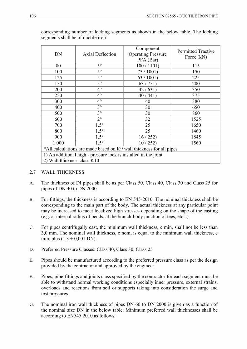
106 SECTION 02565 - DUCTILE IRON PIPE
corresponding number of locking segments as shown in the below table. The locking segments shall be of ductile iron.
DN Axial Deflection Component
Operating Pressure PFA (Bar)
Permitted Tractive Force (kN)
80 5° 100 / 1101) 115 100 5° 75 / 1001) 150 125 5° 63 / 1001) 225 150 5° 63 / 751) 200 200 4° 42 / 631) 350 250 4° 40 / 441) 375 300 4° 40 380 400 3° 30 650 500 3° 30 860 600 2° 32 1525 700 1.5° 25 1650 800 1.5° 25 1460 900 1.5° 16 / 252) 1845
1 000 1.5° 10 / 252) 1560 *All calculations are made based on K9 wall thickness for all pipes 1) An additional high - pressure lock is installed in the joint. 2) Wall thickness class K10
2.7 WALL THICKNESS
A. The thickness of DI pipes shall be as per Class 50, Class 40, Class 30 and Class 25 for pipes of DN 40 to DN 2000.
B. For fittings, the thickness is according to EN 545-2010. The nominal thickness shall be corresponding to the main part of the body. The actual thickness at any particular point may be increased to meet localized high stresses depending on the shape of the casting (e.g. at internal radius of bends, at the branch-body junction of tees, etc...).
C. For pipes centrifugally cast, the minimum wall thickness, e min, shall not be less than 3,0 mm. The nominal wall thickness, e nom, is equal to the minimum wall thickness, e min, plus (1,3 + 0,001 DN).
D. Preferred Pressure Classes: Class 40, Class 30, Class 25
E. Pipes should be manufactured according to the preferred pressure class as per the design provided by the contractor and approved by the engineer.
F. Pipes, pipe-fittings and joints class specified by the contractor for each segment must be able to withstand normal working conditions especially inner pressure, external strains, overloads and reactions from soil or supports taking into consideration the surge and test pressures.
G. The nominal iron wall thickness of pipes DN 60 to DN 2000 is given as a function of the nominal size DN in the below table. Minimum preferred wall thicknesses shall be according to EN545:2010 as follows:
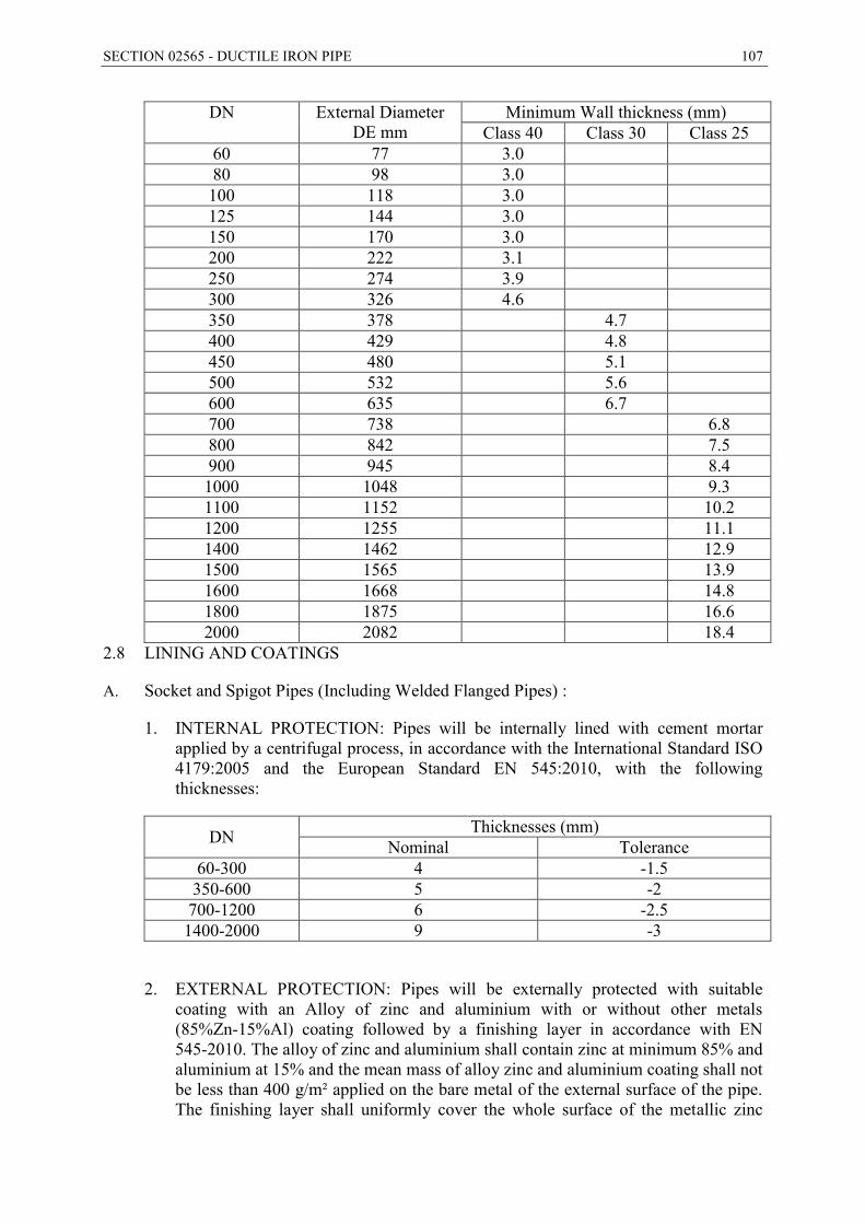
SECTION 02565 - DUCTILE IRON PIPE 107
DN External Diameter DE mm
Minimum Wall thickness (mm) Class 40 Class 30 Class 25
60 77 3.0 80 98 3.0 100 118 3.0 125 144 3.0 150 170 3.0 200 222 3.1 250 274 3.9 300 326 4.6 350 378 4.7 400 429 4.8 450 480 5.1 500 532 5.6 600 635 6.7 700 738 6.8 800 842 7.5 900 945 8.4 1000 1048 9.3 1100 1152 10.2 1200 1255 11.1 1400 1462 12.9 1500 1565 13.9 1600 1668 14.8 1800 1875 16.6 2000 2082 18.4
2.8 LINING AND COATINGS
A. Socket and Spigot Pipes (Including Welded Flanged Pipes) :
1. INTERNAL PROTECTION: Pipes will be internally lined with cement mortar applied by a centrifugal process, in accordance with the International Standard ISO 4179:2005 and the European Standard EN 545:2010, with the following thicknesses:
DN Thicknesses (mm) Nominal Tolerance
60-300 4 -1.5 350-600 5 -2 700-1200 6 -2.5 1400-2000 9 -3
2. EXTERNAL PROTECTION: Pipes will be externally protected with suitable coating with an Alloy of zinc and aluminium with or without other metals (85%Zn-15%Al) coating followed by a finishing layer in accordance with EN 545-2010. The alloy of zinc and aluminium shall contain zinc at minimum 85% and aluminium at 15% and the mean mass of alloy zinc and aluminium coating shall not be less than 400 g/m² applied on the bare metal of the external surface of the pipe. The finishing layer shall uniformly cover the whole surface of the metallic zinc
108 SECTION 02565 - DUCTILE IRON PIPE
aluminium alloy layer and be free from such defects as bare patches or lack of adhesion. The uniformity of the finishing layer shall be checked by visual inspection. When measured in accordance with 6.7, the mean thickness of the finishing layer shall be not less than 70 μm and the local minimum thickness not less than 50 μm.
B. FITTINGS INTERNAL AND EXTERNAL PROTECTION: Fittings will be externally protected against the corrosiveness of soils, The fittings shall be internally and externally protected with a fusion bonded epoxy coating with a minimum dry film thickness of 300 microns, according to the European Standard EN 14901:2006.
2.9 THRUST BLOCKS
A. When specified, concrete thrust blocks shall be installed at each bend, tee, joint and any other location specified by the engineer and in compliance with the thrust block drawings
B. The concrete for the thrust blocks shall conform to the requirements of section 03300 cast in place concrete.
C. Thrust blocks shall be placed against undisturbed earth, where it is unpractical to place the concrete thrust block against undisturbed earth, the fill material placed between the pipe’s bearing surface and the undisturbed soil shall be compacted to a minimum of 95% of the maximum density.
2.10 MARKING
A. All pipes and fittings shall be legibly and durably marked and shall bear at least the following information:
1. The Identification of the Manufacturer and the Manufacturing Unit.
2. The identification of the year of manufacture.
3. The identification as ductile iron.
4. The DN.
5. The Type of joint.
6. The PN rating of flanges when applicable.
7. The reference to this standard.
8. The C class designation of centrifugally cast pipes.
B. The first six markings given above shall be cast-on or cold stamped; the other markings can be applied by any method, e.g. painted on the casting or attached to the packaging.

SECTION 02565 - DUCTILE IRON PIPE 109
2.11 GASKETS AND SEALS
A. The material used for the rubber gaskets shall be an EPDM elastomer, in accordance with ISO 4633:2002 and duly certified as suitable for potable water up to 50°C, by one of the national regulations.
B. Sufficient lubricant as recommended by the pipe manufacturer shall be provided for pipe installation plus ten percent as surplus material. Lubricant containers shall be adequate for extended storage and the pipe manufacturer shall supply instructions for storage limitations and environment.
2.12 FACTORY TESTING
A. Inspection for external appearance, shape, dimensions, and weight shall be carried out on each pipe and fitting. All pipes and fittings shall be sound and free from surface defects.
B. Each pipe centrifugally cast shall be subjected to the hydrostatic pressure test as specified in EN 545-2010. Each fittings and accessory not centrifugally cast shall be subjected to a leak tightness that carried out with water or air as specified in EN 545-2010. Hydrostatic pressure tests shall be performed before the pipes are coated or lined.
C. Any pipe or fitting that leaks or does not withstand the test pressure shall be rejected.
D. Mechanical tests for hardness, tensile strength, and elongation shall be performed on test pipes selected at random out of castings grouped in lots. Each lot shall comprise 200 pipes successively cast.
PART 3 -- EXECUTION
3.1 INSTALLATION OF PIPE
A. Handling and Storage: All pipe, fittings, etc., shall be carefully handled and protected against damage, impact shocks, and free fall. All pipe handling equipment shall be acceptable to the Engineer. Pipe shall not be placed directly on rough ground but shall be supported in a manner which will protect the pipe against injury whenever stored at the trench site or elsewhere. No pipe shall be installed where the lining or coating show defects that may be harmful as determined by the Engineer. Such damaged lining or coating shall be repaired, or a new undamaged pipe shall be furnished and installed.
B. All pipe damaged prior to Substantial Completion shall be repaired or replaced by the CONTRACTOR.
C. The CONTRACTOR shall inspect each pipe and fitting prior to installation to insure that there are no damaged portions of the pipe.
D. Before placement of pipe in the trench, each pipe or fitting shall be thoroughly cleaned of any foreign substance, which may have collected thereon and shall be kept clean at all times thereafter. For this purpose, the openings of all pipes and fittings in the trench shall be closed during any interruption to the Work.
110 SECTION 02565 - DUCTILE IRON PIPE
E. Pipe Laying: The pipe shall be installed in accordance with AWWA C600/BS 8010 standards.
F. Warning Tape: The Contractor shall lay a tape (with a width according to the drawings) below finish grade lines a plastic blue colour (warning tape) of 200 microns thickness, 250 mm wide (as shown in the drawings). The words “Caution water main below” along the top section of the tape shall be written in English and Arabic. Samples of tape shall be submitted to the Engineer for his approval. The waning tape shall not be separately measured or paid for but shall be considered as a subsidiary obligation under the items included in the Bill of quantities
G. Pipe shall be laid directly on the bedding material. No blocking will be permitted, and the bedding shall be such that it forms a continuous, solid bearing for the full length of the pipe. Excavations shall be made as needed to facilitate removal of handling devices after the pipe is laid. Bell holes shall be formed at the ends of the pipe to prevent point loading at the bells or couplings. Excavation shall be made as needed outside the normal trench section at field joints to permit adequate access to the joints for field connection operations and for application of coating on field joints.
H. Each section of pipe 300 mm in diameter and larger shall be laid in the order and position shown on the drawing. In laying pipe, it shall be laid to the set line and grade, within approximately 25 mm plus or minus. On grades of zero slope, the intent is to lay to grade.
I. Where necessary to raise or lower the pipe due to unforeseen obstructions or other causes, the ENGINEER may change the alignment and/or the grades. Such change shall be made by the deflection of joints, or by the use of additional fittings. However, in no case shall the deflection in the joint exceed the maximum deflection recommended by the pipe manufacturer and specification. No joint shall be misfit any amount which will be detrimental to the strength and water tightness of the finished joint.
J. Except for short runs which may be permitted by the ENGINEER, pipes shall not be laid uphill on grades exceeding 10 percent. Pipe which is laid on a downhill grade shall be blocked and held in place until sufficient support is furnished by the following pipe to prevent movement. All bends shall be properly installed as shown.
K. Pipe and Specials Protection: The openings of all pipe and specials shall be protected with suitable bulkheads to prevent unauthorized access by persons, animals, water or any undesirable substance. At all times, means shall be provided to prevent the pipe from floating.
L. Pipe Cleanup: As pipe laying progresses, the CONTRACTOR shall keep the pipe interior free of all debris. The CONTRACTOR shall completely clean the interior of the pipe of all sand, dirt, mortar splatter and any other debris following completion of pipe laying, pointing of joints and any necessary interior repairs prior to testing and disinfecting the completed pipeline.
3.2 TRENCHING AND BACKFILL
A. Trench excavation and backfill shall conform to the requirements of Section 2200 – Earthwork.
SECTION 02565 - DUCTILE IRON PIPE 111
3.3 RUBBER GASKETED JOINTS
A. Rubber Gasketed Joints: Immediately before jointing pipe, the bell end of the pipe shall be thoroughly cleaned, and a clean rubber gasket lubricated with an approved vegetable-based lubricant shall be placed in the bell groove. The spigot end of the pipe shall be carefully cleaned and lubricated with a vegetable-based lubricant. The spigot end of the pipe section shall then be inserted into the bell of the previously laid joint and telescoped into its proper position. Tilting of the pipe to insert the spigot into the bell will not be permitted.
3.4 INSTALLATION OF VALVES
A. Installation of Valves: All valves shall be handled in a manner to prevent any injury or damage to any part of the valve. All joints shall be thoroughly cleaned and prepared prior to installation. The CONTRACTOR shall adjust all stem packing and operate each valve prior to installation to insure proper operation.
B. All valves shall be installed so that the valve stems are plumb and in the location.
3.5 CORROSION CONTROL
A. Wherever required for corrosion control for ductile iron pipelines and fittings, these pipes and fittings shall be fully encased in Tubular Polyethylene film for use as protective sleeving in accordance with ISO 8180, AWWA C105, BS 6076 or other equivalent standards approved by the Engineer.
- END OF SECTION -
112 SECTION 02594 – HIGH DENSITY POLYETHLENE PIPE
SECTION 02594 – HIGH DENSITY POLYETHLENE PIPE
PART 1 -- GENERAL
1.1 THE REQUIREMENT
A. The CONTRACTOR shall furnish and install high-density polyethylene pipe (HDPE), tubing and fittings as shown in the Drawings and as specified herein. The following reference standards shall apply.
DIN EN ISO 178 Determination of the Flexural Properties of Plastics DIN EN ISO 527-2 Determination of tensile properties of plastics – Test
Conditions for Moulding and Extrusion Plastics DIN 1988-2 Drinking water supply systems; materials, components,
appliances, design and installation (DVGW code of practice) DIN 7728–1 Plastics – Symbols for Polymers and Their Special
Characteristics DIN 8074 Polyethylene (PE) Pipes Dimensions DIN 8075 Polyethylene (PE) Pipes General Quality Requirements and
Testing DIN EN ISO 12162 Thermoplastic Materials for pipes and Fittings for Pressure
Applications – Classification, Designation and Overall Service (design) Coefficient
DIN 16963 Pipe Joint Assemblies and Fittings for High – Density Polyethylene (PE-HD) Pressure Pipes
DIN 53752 Determination of Coefficient of Linear Thermal Expansion of Plastics
ISO 4427 Plastic Piping System- Polyethylene (PE) pipes and fittings for water supply
B. The contractor is obligated to comply with the Water Authority of Jordan General Technical Specification
1.2 QUALITY ASSURANCE PROGRAM
A. Qualification of Manufacturers
1. The manufacturer shall have manufacturing and quality control facilities capable of producing and assuring the quality of the pipe and fittings required by these specifications. Given reasonable notice, the Manufacturer’s production facilities shall be open for inspection by the EMPLOYER or his authorized representative. Qualified manufacturers shall be approved by the Engineer.
B. Material
1. Material used for the manufacturing of polyethylene pipe and fittings shall be High Density Polyethylene (HDPE) meeting the DIN/ISO material classification.
2. The material used in the production of potable water pipe shall be meet DIN / DVGW and ISO requirements.
SECTION 02594 – HIGH DENSITY POLYETHLENE PIPE 113
3. The Manufacturer shall certify that the materials used to manufacture pipe and fittings meet the requirements of this specifications.
4. The Minimum Required Strength (MRS) of the material compound shall be 10 MPa at 20°C and 50 years lifetime. The design stress shall be 8 MPa.
5. The concentration of substances, chemical and biological agents leached from materials in contact with drinking water, and measurement of the relevant organoletpic/physical parameters, shall not exceed the maximum values recommended by the World Health Organization in its “Guidelines for Drinking Water Quality” or as required by EEC.
6. The pipes and fittings shall be manufactured from polyethylene containing only those antioxidants, UV stabilizers and pigments necessary for the manufacturing of the pipes and conforming to the requirements of Engineer and the Specification.
7. All pipes and fittings shall be suitable for both the butt fusion or electro fusion welding techniques.
C. Pipe
1. Polyethylene pipe shall be manufactured in accordance with DIN 8074 / 8075 for PE 100, SDR 11, PN16, design stress 8 Mpa.
D. Fittings
1. Polyethylene fittings shall be made from material meeting the same requirements as the pipe. Polyethylene fittings shall be molded or fabricated by the manufacturer of the pipe.
2. Where applicable, fittings shall meet the requirements of DIN 16963.
3. Molded fittings shall be manufactured in accordance with DIN requirements for (socket fused) or (electro-fused) fittings, and shall be marked.
4. Mechanical fittings used with polyethylene pipe shall be specifically designed for, or tested and found to be acceptable for use with polyethylene pipe and approved by the Engineer.
5. The fittings shall be electrofusion type or compression type or push-fit type compatible to PE pipes.
6. At locations where HDPE to metal connections are required, stub flanges with Rislan coated backing rings shall be used, or special restrained transition fittings approved by the Engineer.
E. Inspection of Materials
1. The pipe and fitting manufacturer shall have an established quality control program responsible for inspecting incoming and outgoing materials. Incoming polyethylene materials shall be inspected for density, melt flow rate, and contamination. The cell classification properties of the material shall be certified by the supplier. Incoming
114 SECTION 02594 – HIGH DENSITY POLYETHLENE PIPE
materials shall be approved by Quality Control before processing into finished goods. Outgoing products shall be tested as required in DIN Standards.
2. The CONTRACTOR shall inspect all pipe and accessories for shortages, loss, or damage upon receipt of the shipped material at the time of unloading, recording this information directly on the waybill received from the carrier. If later during the Installation, some material is found to have defects that material shall be rejected by the Engineer. Defective material should be removed from the joining site and not used during the installation. With the approval of the Engineer, pipe may be repaired by cutting out the damaged sections and thermally fusing the remaining acceptable pipe.
3. Acceptable limits for cuts, gouges or scratched are as followed:
O.D. Surface Maximum allowable depth of cut, scratch or gouge shall be 10% of wall thickness.
I.D. Surface Shall be free of all cuts, gouge or scratches.
PART 2 -- PRODUCTS
2.1 PIPE
A. The pipe shall be made from polyethylene resin compound qualified for PE 100, SDR 11, design stress of 8 Mpa.
B. The raw material shall contain a minimum of 2% well dispersed carbon black.
C. The pipe shall contain no recycled compound.
D. Compliance with the requirements of this section shall be certified in writing by the pipe supplier, upon request.
2.2 PIPE DESIGN
A. Polyethylene pipe shall be constructed to a minimum wall thickness of SDR 11 dimension. Pressure rating at 73.4° F (23 c0) 16 bar minimum.
B. The Hydrostatic Design Stress shall be for PE 100 materials.
2.3 PACKING
A. The length of coiled pipe shall be 50-100 m or staraight lengths. If the pipes are to be coiled this must be done at temperature not less than 30°C. For sizes ≥ 63 mm all coils shall be securely banded with tough tape which can’t be removed except by cutting. The minimum internal diameter of the rollers for coiled pipe shall be such that kinking of the pipe is prevented i.e. not less than 18 times the nominal outside diameter of the pipe with a minimum of 600 mm. The ends of the pipe shall be plugged or covered to prevent contamination.
B. The fittings shall be packed in transparent protective bags.
SECTION 02594 – HIGH DENSITY POLYETHLENE PIPE 115
2.4 MARKING
A. Pipe and tubing shall be marked in accordance with DIN requirements. They shall bear permanent identification markings that will remain legible during normal handling, storage, installation, and service life and that have been applied in a manner that will not reduce the strength nor otherwise damage the products. The following shall be continuously marked on the pipe, or spaced at intervals not exceeding 5 feet:
1. Name and/or trademark of the pipe manufacturer.
2. Nominal Pipe Size, diameter and wall thickness.
3. Dimension Ratio (e.g., SDR 11).
4. Standard PE code designation (e.g. PE100).
5. DIN Manufacturing Standard Reference
6. Pressure rating
7. A production code from which date of and place of manufacture can be determined.
B. Fittings shall be marked on the body or hub. Marking shall be in accordance with DIN Standards. Mechanical fittings shall be marked with size, body material designation code, pressure rating and manufacturer’s name or trademark.
2.5 JOINING METHODS
A. Wherever possible, plain end polyethylene pipe and fittings should be joined by the method of electro-fusion.
B. Electro-fusion joining of pipe and fittings shall be performed in accordance with the procedures established by the pipe manufacturer. Joining must be conducted by, or under the supervision of a factory trained manufacturer’s representative.
C. Electro-fusion joining of pipe and fittings shall be performed on fusion machinery approved by the pipe manufacturer. Fusion pressures, temperatures and cycle times shall be according to pipe manufacturer’s recommendations. No pipe or fittings shall be joined by fusion by any Contractor unless he is adequately trained and qualified in the technique involved.
D. The polyethylene pipe, may be adapted to fittings or other pipe elements by means of a suitable flange assembly. Flange assemblies shall consist of the following items:
1. A polyethylene stub end made from the same resin material as the pipe. This stub end shall be factory machined from a molded polyethylene blank made at the pipe manufacturer’s factory.
2. A back-up flange of ductile iron or other suitable material, made to PN 10, DIN dimensional standards. Exceptions to these dimensional standards can be made for systems with exceptionally high operating pressures.
116 SECTION 02594 – HIGH DENSITY POLYETHLENE PIPE
3. Flange assemblies are connected by bolts of compatible material with gaskets, of suitable material for the fluid and pressure characteristics, cut to fit the joint in all cases, the bolts shall be drawn up evenly and in-line, using procedures recommended by the pipe manufacturer.
E. Polyethylene pipe, in sizes from 3 inch (75 mm) IPS to 12 inch (300 mm) IPS, may be alternatively joined by way of specially designed mechanical couplings. These couplings shall include a malleable or ductile iron body, an elastomeric gasket (grade E), and cadmium-plated nuts and bolts.
F. Polyethylene pipes of the same outside diameter, but different wall thicknesses, shall only be joined by means of a flange assembly, suitable mechanical couplings or transition spool places supplied by the pipe manufacturer.
G. Electrofusion Welding: In case of electrofusion welding, all fittings must conform to the requirements of EN 12201-3/ ISO 4427-3 and be suitable to be used in conjunction with pressure pipes from polyethylene manufactured to the appropriate ISO or other standards applicable.
1. The contractor must provide approvals of minimum three internationally recognized authorities such as DVGW, DV, SVGW etc. to guarantee the quality of their products.
2. An individual data career card in compliance with ISO 7810 and ISO 7811 containing a magnetic strip and an appropriate barcode or codes as well as manual setting information for data transfer purpose must be supplied with each fitting.
3. All electrofusion fittings must be packed in transparent protective bags.
4. No hitting coil may be exposed and is to be fully imbedded into the body of the fitting for protection purposes during assembly.
5. All fittings must have moulded-in identification and product information
6. The contractor shall provide certificates from a third party demonstrating that all the tests in accordance the applicable ISO/ EN are performed on electrofusion assemblies, namely the tests as per ISO 13954 and ISO 13955.
7. The contractor’s staff responsible for Electrofusion welding must provide a welding certificate of the manufacturer.
2.6 MITRED FITTINGS
A. Mitred fittings (e.g. elbows, wyes and tees) shall be designed with additional material in areas subject to high stress. The common commercial practice is to increase wall thickness in high-stress areas by using heavy-wall pipe sections. This is similar to molded fittings that are molded with heavier body wall thickness. Reinforced overwraps may be used to increase the pressure rating of a fitting. All fittings shall be assembled using the but-fusion technique under factory conditions, under the supervision of the pipe manufacturer.
SECTION 02594 – HIGH DENSITY POLYETHLENE PIPE 117
B. Mitred fittings shall be available from the pipe manufacturer with either flanged or plain ends.
PART 3 -- EXECUTION
3.1 GENERAL
A. The polyethylene (PE) pipe shall be installed in accordance with the instructions of the pipe manufacturer and as shown in the drawings.
B. The trench should be dug to the required alignment and depth shown on the contract drawings.
C. Pipe shall be laid to lines and grade shown on the drawings, with bedding and backfill as specified on the drawings.
D. In all cases where polyethylene pipe is installed, a detectable metallic tape shall be installed in the pipe trench parallel and one foot (300 mm) above the top of the pipe. The metallic tape shall consist of a minimum thickness of 0.35 mils solid aluminum foil core running in a protective, high-visibility, color-coded plastic jacket that is impervious to corrosive soil conditions. The tape shall be a minimum of 6 inches (15 cm) wide with a minimum overall thickness of 5.0 mils. The tape shall meet or exceed the industry standards and DIN requirements. The tape shall be permanently printed with lettering which reads: “Caution – Water Line Buried Below ” in Arabic and English.
E. The design of the embedment shall be to ensure that external loads will not subsequently cause a decrease in the vertical cross-section dimension (deflection) greater than the percentages recommended by the pipe manufacturer.
F. Backfill and compaction shall be in accordance with the pipe manufacturer’s recommendations. Compaction density testing shall be done at the level of the pipe springline and at the level of the top of the pipe at intervals not exceeding 400 feet.
G. Polyethylene flanges must be at the ambient temperature of the surrounding soil at the time they are bolted tight to prevent relaxation of the flange bolts and loosening of the joint due to thermal contraction of the polyethylene. Flange bolts must be re-tightened at least once 24 hours after initial flange bolt tightening.
H. All polyethylene pipes must be at the temperature of the surrounding soil at the time it is backfilled and compacted.
3.2 HANDLING OF PIPE OF MATERIALS
A. Pipe and fittings shall be handled carefully at all times to avoid damage. Straight lengths of pipe can be safely unloaded using mobile handling equipment capable of lifting the weight of pipe to a height that will allow the complete pipe length to clear truck side racks. Wide belly-band slings are commended for handling straight lengths of pipe. Thick nylon rope slings may also be used, either in an inverted “Y” or with a spreader beam to distribute the weight evenly over two lifting points. Forklifts or mobile cranes can be used to move straight lengths of pipe, providing that the load is lifted at mid-point. Forks shall be checked for ragged edges or burrs. These shall be removed or the forks wrapped to prevent damage to the pipe. Under no circumstances should hooks
118 SECTION 02594 – HIGH DENSITY POLYETHLENE PIPE
be inserted into the pipe ends to lift pipe. Dragging the pipe over gravel or rock shall be avoided, as this may cause cutting whereas pulling over reasonably smooth terrain (e.g. sand or topsoil) will not damage the pipe.
3.3 STORAGE OF PIPE AND FITTINGS
A. Storage of the pipe on the job site shall be done in accordance with the pipe manufacturer’s recommendation.
B. Recommended ground conditions are leveled gravel, sand, topsoil or grass. The interior of all pipe and fittings shall be kept free of debris and lifting equipment at all times.
C. Pipe shall be piled in a free-standing manner with wide-face wooden chocks restraining the bottom layer.
3.4 THERMAL FUSION FABRICATION
A. Electro-fusion joining of pipe and fittings shall be performed in accordance with the procedures established by the pipe manufacturer. Joining must be conducted by, or under the supervision of a factory-trained manufacturer’s representative.
B. Electro-fusion joining of pipe and fittings shall be performed on fusion machinery approved by the pipe manufacturer. Fusion pressures, temperatures and cycle times shall be according to pipe manufacturer’s recommendations. No pipe or fittings shall be joined by fusion by any Contractor unless he is adequately trained and qualified in the techniques involved.
C. Joining sites should be cleared and graded if necessary, to provide enough space for pipe storage and fusion. The site shall be free of rocks, stumps and debris which could cut, scar or gouge the pipe. The fusion machine must be mounted on a level, stable base (e.g. ¾ inch plywood secured on level ground) or on a sled of a design approved by the pipe manufacturer. In order to allow the joining operation to continue in adverse weather conditions, a shelter shall be built for the joining machine.
D. Barcode labelled or auto recognition electro fusion jointing shall be used and only fittings incorporating fusion indicators shall be acceptable. The equipment used for joint construction shall provide fusion data in the form of a print out specific to each joint, which shall include each joint's unique joint number. These print outs shall form part of the as built records.
E. The electro fusion control box shall deliver the correct fusion parameters to the electro fusion fitting. The power generator shall provide the power requirements of the control box, taking into account the electrical characteristics of the control box. Positioning tools shall be used for all types of electro fusion systems to minimize misalignment and prevent movement during cooling of the joint.
F. The inspection (acceptance standards) shall include the following:
1. A uniform and efficient scraping over the entire circumference shall be clearly visible on either side of the socket.
SECTION 02594 – HIGH DENSITY POLYETHLENE PIPE 119
2. A dot or line shall be initially marked on the pipe or spigot end to determine/confirm the depth of penetration. If a clamping/scraping tool is used which indicates the depth of penetration, then the marking requirement no longer applies. Each pipe or spigot end shall penetrate completely its relevant part of the electro-socket.
3. Melt from the fusion process shall not exude outside the confines of the fitting. If the fitting is designed with fusion indicators, after the fusion they shall be in a position complying with the fitting Manufacturer's instructions.
4. Alignment clamps shall not be removed before the appropriate cooling time has elapsed.
5. Abnormal displacement of the electric wire coils shall not occur. This shall be checked prior to commencement of fusion.
6. E-Fusion welders shall held a welding certificate.
3.5 TRENCHING, BACKFILLING AND COMPACTION
A. Backfill material shall be clean earth fill composed of materials as per Section 02200, “Earthwork”.
B. The Contractor shall perform all clearing necessary for the proper installation of piping and appurtenances in the locations shown on the drawings.
C. All pipe and fittings should be laid “in the dry” unless otherwise approved. Trench excavations may be dewatered by using well point systems, sumps with pumps or by other methods approved by the Engineer. Dewatering systems shall be utilized in accordance with good standard practice and must be efficient enough to lower the water level in advance of the excavation and maintain it continuously to keep the trench bottom and sides firm and dry.
D. Trench Dimensions: The minimum clear width of unsheathed or shored trench, measured at the horizontal diameter of the pipe, should be 200 mm greater than the outside diameter of the pipe. The maximum clear width at the top of the pipe should be 500 mm.
E. Initial backfill should be compacted per manufacturer’s recommendations or Section 02200 “Earthwork”. Compaction should be carried out in 6-inch layers until the top of the pipe is reached. Compaction directly over the pipe should be avoided with less than one foot of cover on top of the pipe.
3.6 INSTALLATION OF FITTINGS AND VALVES
A. All fittings should be carefully inspected and cleaned before being carefully lowered into the trench. Well compacted (90 percent Standard Proctor Density of greater) crushed stone or gravel shall be applied in six inch layers (extending to the trench walls) at all elbows, tees, wyes and other fittings so that the fittings are encased in stable backfill. The compacted material shall extend a minimum distance of three pipe diameters beyond the ends of the fitting.
120 SECTION 02594 – HIGH DENSITY POLYETHLENE PIPE
B. Where polyethylene pipe is connected to flanged pipe or fittings fixed in a rigid structure, such as a valve pit or manhole, a reinforced concrete pad shall be poured under the pipe and the flange, and the pad connected to the structure by means of a reinforcing rod. This support shall extend from the flanged joint: a minimum of one pipe diameter.
3.7 HYDROSTATIC TESTING OF HDPE
A. Installed HDPE piping is to be field hydrostatic tested per Section 02643. The Contractor shall supply all labor, equipment, material, gauges, pumps and incidentals required for testing.
B. Testing shall be completed after backfilling has been completed, but before placement of permanent surface.
C. The testing procedure shall be as follows:
1. Fill the line slowly with water. Maintain flow velocity at less than 2 feet (0.6 m) per second.
2. The test procedure consists of two steps: the initial expansion phase and the test period. In order to accommodate the initial expansion of the pipe under test, sufficient make-up water is added to the system at hourly intervals for 3 hours, returning the piping system to the Test Pressure. After the completion of the initial expansion phase, (e.g. 4 hours after initially pressurizing the piping system under test), the actual test period shall begin. The Test period must not exceed 3 hours. After this Test Period, a measured amount of make-up water should be added to return the piping system to the Test Pressure. The amount of make-up water should not exceed the allowance recommended by PPI or the pipe manufacturer.
NOTE: Under no circumstances should the total time under test exceed eight (8) hours at 1.5 times the pressure rating. If the test is not completed due to leakage, equipment failure or any other reason within this time period, the test section should be permitted to “relax” for an additional eight hour period prior to starting the next testing sequence.
D. If any test of the pipe laid requires more make-up water than the allowance specified,
the Contractor shall, at his own expense, locate and repair the cause of the leakage and retest the lines.
E. All visible leaks are to be repaired regardless of the amount of leakage.
3.8 CLEANING
A. At the conclusion of the work, the Contractor shall thoroughly clean all the installed pipe lines by flushing with water or other means to remove all dirt, stones, pieces of wood or other material which may have entered the pipe line during the construction period. Debris cleaned from the lines shall be removed from the job site. If, after this cleaning, any obstructions remain, they shall be removed by the Contractor.

SECTION 02594 – HIGH DENSITY POLYETHLENE PIPE 121
3.9 WARNING TAPE
A. The Contractor shall lay 80 cm below finish grade lines a plastic blue colour (warning tape) of 200 microns thickness, 250 mm wide (as shown in the drawings). The words “Caution water main below” along the top section of the tape shall be written in English and Arabic. Samples of tape shall be submitted to the Engineer for his approval.
B. The waning tape shall not be separately measured or paid for but shall be considered as a subsidiary obligation under the items included in the Bill of quantities
C. Pipe shall be laid directly on the bedding material. No blocking will be permitted, and the bedding shall be such that it forms a continuous, solid bearing for the full length of the pipe. Excavations shall be made as needed to facilitate removal of handling devices after the pipe is laid. Bell holes shall be formed at the ends of the pipe to prevent point loading at the bells or couplings. Excavation shall be made as needed outside the normal trench section at field joints to permit adequate access to the joints for field connection operations and for application of coating on field joints.
D. Each section of pipe 300 mm in diameter and larger shall be laid in the order and position shown on the drawing. In laying pipe, it shall be laid to the set line and grade, within approximately 25 mm plus or minus. On grades of zero slope, the intent is to lay to grade.
E. Where necessary to raise or lower the pipe due to unforeseen obstructions or other causes, the ENGINEER may change the alignment and/or the grades. Such change shall be made by the deflection of joints, by the use of bevel adapters, or by the use of additional fittings. However, in no case shall the deflection in the joint exceed the maximum deflection recommended by the pipe manufacturer. No joint shall be misfit any amount which will be detrimental to the strength and water tightness of the finished joint.
F. Except for short runs which may be permitted by the Engineer, pipes shall be laid uphill on grades exceeding 10 percent. Pipe which is laid on a downhill grade shall be blocked and held in place until sufficient support is furnished by the following pipe to prevent movement. All bends shall be properly installed as shown.
G. Pipe and Specials Protection: The openings of all pipe and specials shall be protected with suitable bulkheads to prevent unauthorized access by persons, animals, water or any undesirable substance. At all times, means shall be provided to prevent the pipe from floating.
H. Pipe Cleanup: As pipe laying progresses, the Contractor shall keep the pipe interior free of all debris. The Contractor shall completely clean the interior of the pipe of all sand, dirt, mortar splatter and any other debris following completion of pipe laying, pointing of joints and any necessary interior repairs prior to testing and disinfecting the completed pipeline.
– END OF SECTION –
122 SECTION 02643 – WATER TESTING AND DISINFECTION
SECTION 02643 – WATER TESTING AND DISINFECTION
PART 1 -- GENERAL
1.1 THE REQUIREMENT
A. The CONTRACTOR shall perform flushing and testing of all pipelines and appurtenant piping and disinfection of all pipelines and appurtenant piping for potable water, complete, in accordance with the Contract Documents.
B. All pipes including those will be removed and reconnected along with all components incorporated shall be disinfected prior to connection.
1.2 CONTRACTOR SUBMITTALS
A. A proposed plan and schedule for water conveyance, cleaning, pressure testing, disinfection, and water disposal shall be submitted in writing for approval a minimum of 48 hours before testing is to start. The plan shall demonstrate that personnel are experienced and prepared to resolve problems which may arise.
PART 2 -- PRODUCTS
2.1 MATERIALS REQUIREMENTS
A. All test equipment, chemicals for chlorination, temporary valves, bulkheads, or other water control equipment and materials shall be selected and furnished by the CONTRACTOR subject to the ENGINEER's review. No materials shall be used which would be injurious to the construction or its future function.
B. Chlorine for disinfection may be in the form of liquid chlorine, sodium hypochlorite solution, or calcium hypochlorite granules or tablets.
C. Liquid chlorine shall be in accordance with the requirements of AWWA C651. Liquid chlorine shall be used only:
1. In combination with appropriate gas flow chlorinators and ejectors;
2. Under the direct supervision of an experienced technician;
3. When appropriate safety practices are observed.
D. Sodium hypochlorite and calcium hypochlorite shall be in accordance with the requirements of AWWA C651.
PART 3 -- EXECUTION
3.1 GENERAL
A. Unless otherwise indicated, water for testing and disinfecting water pipelines will be furnished by CONTRACTOR
B. All pressure pipelines shall be tested.

SECTION 02643 – WATER TESTING AND DISINFECTION 123
C. Disinfection shall be accomplished by chlorination. All chlorinating and testing operations shall be performed in the presence of the ENGINEER.
D. Disinfection operations shall be scheduled by the CONTRACTOR as late as possible during the contract time period so as to assure the maximum degree of sterility of the facilities at the time the WORK is accepted by the EMPLOYER. Bacteriological testing shall be performed by a certified testing laboratory approved by the EMPLOYER and at the expense of the CONTRACTOR. Results of the bacteriological testing shall be satisfactory to the Ministry of Health or other appropriate local regulatory agency.
3.2 PIPE FLUSHING
A. The CONTRACTOR shall clean the system thoroughly by flushing, including pigging wherever required, to remove sand, grit, gravel, stones, fluids, construction waste, and all material which would not be found in a properly cleaned pipeline. Flushing shall obtain a smooth interior pipe surface free from any material or fluid not used in cleaning.
B. Pigging shall be defined as passage of a sufficient number of pigs through the pipeline to achieve the clean conditions above.
C. Provision for pig access and egress points and disposal of water and materials shall be the CONTRACTOR's responsibility.
D. Pigs shall be individually marked and their location shall be controlled and monitored so that no pigs remain in the system after cleaning.
3.3 HYDROSTATIC TESTING OF PIPELINES
A. Prior to hydrostatic testing, pipelines shall be flushed or blown out as appropriate. The CONTRACTOR shall test all pipelines either in sections or as a unit. No section of the pipeline shall be tested until all field-placed concrete or mortar has attained an age of 14 days. The test shall be made by closing valves when available, or by placing temporary bulkheads in the pipe and filling the line slowly with water. The CONTRACTOR shall be responsible for ascertaining that all test bulkheads are suitably restrained to resist the thrust of the test pressure without damage to, or movement of, the adjacent pipe. Any unharnessed sleeve-type couplings, expansion joints, or other sliding joints shall be restrained or suitably anchored prior to the test, to avoid movement and damage to piping and equipment. The CONTRACTOR shall provide sufficient temporary air tappings in the pipelines to allow for evacuation of all entrapped air in each pipe segment to be tested. After completion of the tests, such taps shall be permanently plugged. Care shall be taken to see that all air vents are open during filling.
B. The pipeline shall be filled at a rate which will not cause any surges or exceed the rate at which the air can be released through the air valves at a reasonable velocity and all the air within the pipeline shall be properly purged. After the pipeline or section thereof has been filled, it shall be allowed to stand under a slight pressure for at least 24 hours to allow the concrete or mortar lining, as applicable, to absorb what water it will and to allow the escape of air from any air pockets. During this period, bulkheads, valves, and connections shall be examined for leaks. If leaks are found, corrective measures satisfactory to the ENGINEER shall be taken.
124 SECTION 02643 – WATER TESTING AND DISINFECTION
C. The hydrostatic test shall consist of holding the test pressure on the pipeline for a period of 4 hours. The test pressure for distribution and transmission pipelines shall be 133 percent of the pipe pressure class indicated, measured at the lowest point of the pipeline section being tested or 125 percent of the pipe pressure class indicated, measured at the highest point of the pipeline section being tested. All visible leaks shall be repaired in a manner acceptable to the ENGINEER.
D. The maximum allowable leakage for distribution and transmission pipelines shall be according to the following formula:
L = S x D x P1/2 / 7042 where:
L = leakage (liters per hour) S = length (meters), the lessor of the actual length being tested or the
maximum length for determining leakage. Maximum length for determining leakage is 600 meters.
D = pipe diameter (mm) P = test pressure (bar)
E. Pipelines that fail to pass the prescribed leakage test will be considered defective
WORK, and the CONTRACTOR shall determine the cause of the leakage, shall take corrective measures necessary to repair the leaks, and shall retest the pipelines.
3.4 DISINFECTING PIPELINES
A. General: All potable water pipelines except those appurtenant to hydraulic structures shall be disinfected in accordance with the requirements of ANSI/AWWA C651 using the Continuous-Feed Method as modified herein or equivalent.
B. Chlorination: A chlorine-water solution shall be uniformly introduced into the pipeline by means of a solution-feed chlorinating device. The chlorine solution shall be introduced at one end of the pipeline through a tap in such a manner that as the pipeline is filled with water, the concentration in the water entering the pipe is approximately 50 mg/l. Care shall be taken to prevent the strong chlorine solution in the pipeline being disinfected from flowing back into the line supplying the water.
C. Retention Period: Chlorinated water shall be retained in the pipeline long enough to destroy all non-spore-forming bacteria. This period shall be at least 24 hours. After the chlorine-treated water has been retained for the required time, the free chlorine residual at the pipeline extremities and at other representative points shall be at least 25 mg/l.
D. Chlorinating Valves: During the process of chlorinating the pipelines, all valves and other appurtenances shall be operated while the pipeline is filled with the heavily-chlorinated water.
E. Sampling Ports: The CONTRACTOR shall provide sampling ports along the pipeline. Taps may be made at manways and air valves to help facilitate the spacing requirement.
SECTION 02643 – WATER TESTING AND DISINFECTION 125
F. Final Flushing: After the applicable retention period, the heavily chlorinated water shall be flushed from the pipeline until chlorine measurements show that the concentration in the water leaving the pipeline is no higher than that generally prevailing in the system or is acceptable for domestic use. If there is any question that the chlorinated discharge will cause damage to the environment, a reducing agent shall be applied to the water to neutralize thoroughly the chlorine residual remaining in the water.
G. Bacteriological Testing: After final flushing and before the pipeline is placed in service, a sample, or samples shall be collected from the end of the line, and shall be tested for bacteriological quality in accordance with the requirements of the appropriate regulatory agency. For this purpose the pipe shall be re-filled with fresh potable water and left for a period of 24 hours before any sample is collected. Should the initial disinfection treatment fail to produce satisfactory bacteriological test results, the disinfection procedure shall be repeated until acceptable results are obtained.
H. Disinfecting of pipes shall not be done concurrently with hydrostatic testing
3.5 CONNECTIONS TO EXISTING SYSTEM
A. Where connections are to be made to an existing potable water system, the interior surfaces of all pipe and fittings used in making the connections shall be swabbed or sprayed with a one percent hypochlorite solution before they are installed. Thorough flushing shall be started as soon as the connection is completed and shall be continued until discolored water is eliminated.
- END OF SECTION-
126 SECTION 03100 - CONCRETE FORMWORK
DIVISION 03: CONCRETE
SECTION 03100 - CONCRETE FORMWORK
PART 1 -- GENERAL
1.1 THE REQUIREMENT
A. The Contractor shall furnish concrete formwork, bracing, shoring, and supports and shall design and construct falsework in accordance with the Contract Documents.
1.2 REFERENCE SPECIFICATIONS, CODES, AND STANDARDS
A. Governmental Standards:
PS 1 Construction and Industrial Plywood PS 20 American Softwood Lumber Standard
B. Commercial Standards:
ACI 117 Standard Tolerances for Concrete Construction and Materials ACI 347 Guide to Formwork for Concrete
1.3 CONTRACTOR SUBMITTALS
A. Furnish submittals in accordance with Section 01300 - Contractor Submittals.
B. Manufacturer’s information demonstrating compliance with requirements.
1. Form ties and related accessories, including taper tie plugs, if taper ties are used.
2. Form gaskets.
3. Form release agent, including NSF certification.
4. List of form materials and locations for use.
C. Shop Drawings: Detailed plans of the falsework proposed to be used. Such plans shall be in sufficient detail to indicate the general layout, sizes of members, anticipated stresses, grade of materials to be used in the falsework, means of protecting existing construction which supports falsework, and typical soil conditions. Include a list of form materials and locations for use.
D. Falsework Calculations and Drawings: Falsework or vertical shoring installations where the height of the falsework or vertical shoring, as measured from the top of the sills to the soffit of the superstructure, exceeds 4.5 m, or where individual horizontal span lengths exceed 5.0 m, or provision for vehicular or railroad traffic through falsework or vertical shoring is made, shall be approved and signed by the Engineer, provided further, that a copy of the falsework plan or shoring layout shall be available on the job site at all times.
SECTION 03100 - CONCRETE FORMWORK 127
1.4 QUALITY ASSURANCE
A. Tolerances: The variation from required lines or grade shall not exceed 30 mm in 3 m and there shall be no offsets or visible waviness in the finished surface. All other tolerances shall be within the tolerances of ACI 117.
PART 2 -- PRODUCTS
2.1 GENERAL
A. Except as otherwise expressly accepted by the Engineer, lumber brought on the Site for use as forms, shoring, or bracing shall be new material. Forms shall be smooth surface forms and shall be of the following materials:
1. Walls - Steel or plywood panel
2. Columns - Steel, plywood or fiber glass
3. Roof and floor - Plywood
4. All other work - Steel panels, plywood or tongue and groove lumber
2.2 FORM AND FALSEWORK MATERIALS
A. Materials for concrete forms, formwork, and falsework shall conform to the following requirements:
1. Plywood for concrete formwork shall be new, waterproof, synthetic resin bonded, and shall be edge sealed.
2. Form materials shall be metal, wood, plywood, or other material that will not adversely affect the concrete and will facilitate placement of concrete to the shape, form, line, and grade indicated. Metal forms shall accomplish such results.
B. Unless otherwise indicated, exterior corners in concrete members shall be provided with 20 mm chamfers or be tooled to 12.5 mm radius. Re-entrant corners in concrete members shall not have fillets unless otherwise indicated.
C. Forms and falsework to support the roof and floor slabs shall be designed for the total dead load, plus a live load of 50 psf (800 Kg/m2) minimum. The minimum design load for combined dead and live loads shall be 100 psf (1600 Kg/m2).
2.3 FORM TIES
A. Form ties shall be provided with a plastic cone or other suitable means for forming a conical hole to insure that the form tie may be broken off back of the face of the concrete. The maximum diameter of removable cones for rod ties, or of other removable form-tie fasteners having a circular cross-section, shall not exceed 38 mm; and all such fasteners shall be such as to leave holes of regular shape for reaming. Form ties for water-retaining structures shall have integral waterstops that tightly fit the form tie so that they cannot be moved from mid-point of the tie.
128 SECTION 03100 - CONCRETE FORMWORK
B. Removable taper ties may be used when approved by the Engineer. A preformed neoprene or polyurethane tapered plug sized to seat at the center of the wall shall be inserted in the hole left by the removal of the taper tie.
PART 3 -- EXECUTION
3.1 GENERAL
A. Forms to confine the concrete and shape it to the required lines shall be used wherever necessary. The Contractor shall assume full responsibility for the adequate design of all forms, and any forms which are unsafe or inadequate in any respect shall promptly be removed from the WORK and replaced. Provide worker protection from protruding reinforcement bars in accordance with applicable safety codes. A sufficient number of forms of each kind shall be available to permit the required rate of progress to be maintained. The design and inspection of concrete forms, falsework, and shoring shall comply with applicable local, state and Federal regulations. Plumb and string lines shall be installed before concrete placement and shall be maintained during placement. Such lines shall be used by Contractor's personnel and by the Engineer and shall be in sufficient number and properly installed. During concrete placement, the Contractor shall continually monitor plumb and string line form positions and immediately correct deficiencies.
B. Concrete forms shall conform to the shape, lines, and dimensions of members required, and shall be substantial, free from surface defects, and sufficiently tight to prevent leakage. Forms shall be properly braced or tied together to maintain their position and shape under a load of freshly-placed concrete. If adequate foundation for shores cannot be secured, trussed supports shall be provided.
3.2 FORM DESIGN
A. Forms shall be true in every respect to the required shape and size, shall conform to the established alignment and grade, and shall be of sufficient strength and rigidity to maintain their position and shape under the loads and operations incident to placing and vibrating the concrete. Suitable and effective means shall be provided on all forms for holding adjacent edges and ends of panels and sections tightly together and in accurate alignment so as to prevent the formation of ridges, fins, offsets, or similar surface defects in the finished concrete. Plywood, 16 mm and greater in thickness, may be fastened directly to studding if the studs are spaced close enough to prevent visible deflection marks in the concrete. The forms shall be tight so as to prevent the loss of water, cement and fines during placing and vibrating of the concrete. Specifically, the bottom of wall forms that rest on concrete footings or slabs shall be provided with a gasket to prevent loss of fines and paste during placement and vibration of concrete. Such gasket may be a 25 to 38 mm diameter polyethylene rod held in position to the underside of the wall form. Adequate clean-out holes shall be provided at the bottom of each lift of forms. The size, number, and location of such clean-outs shall be as acceptable to the Engineer. Whenever concrete cannot be placed from the top of a wall form in a manner that meets the requirements of the Contract Documents, form windows shall be provided in the size and spacing needed to allow placement of concrete to the requirements of Section 03300 - Cast-in-Place Concrete. The size, number, and location of such form windows shall be as acceptable to the Engineer.
SECTION 03100 - CONCRETE FORMWORK 129
3.3 CONSTRUCTION
A. Vertical Surfaces: All vertical surfaces of concrete members shall be formed, except where placement of the concrete against the ground is indicated. Not less than 25mm of concrete shall be added to the indicated thickness of a concrete member where concrete is permitted to be placed against trimmed ground in lieu of forms. Permission to do this on other concrete members will be granted only for members of comparatively limited height and where the character of the ground is such that it can be trimmed to the required lines and will stand securely without caving or sloughing until the concrete has been placed.
B. Construction Joints: Concrete construction joints will not be permitted at locations other than those indicated, except as may be acceptable to the Engineer. When a second lift is placed on hardened concrete, special precautions shall be taken in the way of the number, location, and tightening of ties at the top of the old lift and bottom of the new to prevent any unsatisfactory effect whatsoever on the concrete. Pipe stubs and anchor bolts shall be set in the forms where required.
C. Form Ties:
1. Embedded Ties: Holes left by the removal of form tie cones shall be reamed with suitable toothed reamers so as to leave the surface of the holes clean and rough before being filled with mortar. Wire ties for holding forms will not be permitted. No form-tying device or part thereof, other than metal, shall be left embedded in the concrete. Ties shall not be removed in such manner as to leave a hole extending through the interior of the concrete members. The use of snap-ties which cause spalling of the concrete upon form stripping or tie removal will not be permitted. If steel panel forms are used, rubber grommets shall be provided where the ties pass through the form in order to prevent loss of cement paste. Where metal rods extending through the concrete are used to support or to strengthen forms, the rods shall remain embedded and shall terminate not less than 1-inch (25mm) back from the formed face or faces of the concrete.
2. Removable Ties: Where taper ties are approved for use, the larger end of the taper tie shall be on the wet side of walls in water retaining structures. After the taper tie is removed, the hole shall be thoroughly cleaned and roughened for bond. A precast neoprene or polyurethane tapered plug shall be located at the wall centerline. The hole shall be completely filled with non-shrink grout for water bearing and below-grade walls. The hole shall be completely filled with non-shrink or regular cement grout for above-grade walls which are dry on both sides. Exposed faces of walls shall have the outer 50 mm of the exposed face filled with a cement grout which shall match the color and texture of the surrounding wall surface.
3.4 REUSE OF FORMS
A. Forms may be reused only if in good condition and only if acceptable to the Engineer. Light sanding between uses will be required wherever necessary to obtain uniform surface texture on all exposed concrete surfaces. Exposed concrete surfaces are defined as surfaces which are permanently exposed to view. In the case of forms for the inside wall surfaces of hydraulic/water retaining structures, unused tie rod holes in forms shall

130 SECTION 03100 - CONCRETE FORMWORK
be covered with metal caps or shall be filled by other methods acceptable to the Engineer.
3.5 REMOVAL OF FORMS
A. Careful procedures for the removal of forms shall be strictly followed, and this work shall be done with care so as to avoid injury to the concrete. No heavy loading on green concrete will be permitted. In the case of roof slabs and above-ground floor slabs, forms shall remain in place until test cylinders for the roof concrete attain a minimum compressive strength of 75 percent of the 28-day strength in Section 03300 - Cast-in-Place Concrete. No forms shall be disturbed or removed under an individual panel or unit before the concrete in the adjacent panel or unit has attained 75 percent of the 28-day strength and has been in place for a minimum of 7 days. The time required to establish said strength shall be as determined by the Engineer who will make several test cylinders for this purpose from concrete used in the first group of roof panels placed. If the time so determined is more than the 7-day minimum, then that time shall be used as the minimum length of time. Forms for vertical walls of waterholding structures shall remain in place at least 36 hours after the concrete has been placed. Forms for parts of the WORK not specifically mentioned herein shall remain in place for periods of time as recommended in ACI 347.
3.6 MAINTENANCE OF FORMS
A. Forms shall be maintained at all times in good condition, particularly as to size, shape, strength, rigidity, tightness, and smoothness of surface. Before concrete is placed, the forms shall be thoroughly cleaned. The form surfaces shall be treated with a nonstaining mineral oil or other lubricant acceptable to the Engineer. Any excess lubricant shall be satisfactorily removed before placing the concrete. Where field oiling of forms is required, the Contractor shall perform the oiling at least two weeks in advance of their use. Care shall be exercised to keep oil off the surfaces of steel reinforcement and other metal items to be embedded in concrete.
3.7 FALSEWORK
A. The Contractor shall be responsible for the design, engineering, construction, maintenance, and safety of all falsework, including staging, walkways, forms, ladders, and similar appurtenances, which shall equal or exceed the requirements of this section.
B. Falsework shall be designed and constructed to provide the necessary rigidity and to support the loads. Falsework for the support of a superstructure shall be designed to support the loads that would be imposed if the entire superstructure were placed at one time.
C. Falsework shall be placed upon a solid footing, safe against undermining, and protected from softening. When the falsework is supported on timber piles, the maximum calculated pile loading shall not exceed 20 tons (18,150 kg). When falsework is supported on any portion of the structure which is already constructed, the load imposed by the falsework shall be spread, distributed, and braced in such a way as to avoid any possibility of damage to the structure.
– END OF SECTION –
SECTION 03200 - REINFORCEMENT STEEL 131
SECTION 03200 - REINFORCEMENT STEEL
PART 1 -- GENERAL
1.1 THE REQUIREMENT
A. The Contractor shall furnish, fabricate, and place all concrete reinforcement steel, welded wire fabric, couplers, and concrete inserts for use in reinforced concrete and masonry construction and shall perform all appurtenant work, including all the wires, clips, supports, chairs, spacers, and other accessories, all in accordance with the Contract Documents.
1.2 REFERENCE SPECIFICATIONS, CODES, AND STANDARDS
A. Commercial Standards
ACI 315 Details and Detailing of Concrete Reinforcement ACI 318 Building Code Requirements for Reinforced Concrete CRSI MSP-1 Concrete Reinforcing Steel Institute Manual of Standard
Practice WRI Manual of Standard Practice for Welded Wire Fabric AWS D1.4 Structural Welding Code - Reinforcing Steel ASTM A 82 Steel Wire, Plain, for Concrete Reinforcement ASTM A 185 Welded Steel Wire Fabric, Plain, for Concrete Reinforcement ASTM A 615 Deformed and Plain Billet-Steel Bars for Concrete
Reinforcement ASTM A 775 Epoxy-Coated Reinforcing Steel Bars
1.3 CONTRACTOR SUBMITTALS
A. The Contractor shall furnish shop bending diagrams, placing lists, and drawings of all reinforcement steel prior to fabrication in accordance with the requirements of Section 01300 - Contractor Submittals.
B. Details of the concrete reinforcement steel and concrete inserts shall be submitted by the Contractor at the earliest possible date after receipt by the Contractor of the Notice to Proceed. Said details of reinforcement steel for fabrication and erection shall conform to ACI 315 and the requirements specified and shown. The shop bending diagrams shall show the actual lengths of bars, to the nearest centimeter measured to the intersection of the extensions (tangents for bars of circular cross section) of the outside surface. The shop drawings shall include bar placement diagrams which clearly indicate the dimensions of each bar splice.
C. Where mechanical couplers are required or permitted to be used to splice reinforcement steel, the Contractor shall submit manufacturer's literature which contains instructions and recommendations for installation for each type of coupler used; certified test reports which verify the load capacity of each type and size of coupler used; and shop drawings which show the location of each coupler with details of how they are to be installed in the formwork.
D. If reinforcement steel is spliced by welding at any location, the Contractor shall submit mill test reports which shall contain the information necessary for the determination of
132 SECTION 03200 - REINFORCEMENT STEEL
the carbon equivalent as specified in AWS D1.4. The Contractor shall submit a written welding procedure for each type of weld for each size of bar which is to be spliced by welding; merely a statement that AWS procedures will be followed is not acceptable.
1.4 QUALITY ASSURANCE
A. If requested by the Engineer, the Contractor shall provide samples from each heat of reinforcement steel delivered in a quantity adequate for testing. Costs of initial tests will be paid by the Employer. Costs of additional tests due to material failing initial tests shall be paid by the Contractor.
B. If reinforcement steel is spliced by welding at any location, the Contractor shall submit certifications of procedure qualifications for each welding procedure used and certification of welder qualifications, for each welding procedure, and for each welder performing the work. Such qualifications shall be as specified in AWS D1.4.
C. If requested by the Engineer, the Contractor shall provide samples of each type of welded splice used in the work in a quantity and of dimensions adequate for testing. At the discretion of the Engineer, radiographic testing of direct butt welded splices will be performed. The Contractor shall provide assistance necessary to facilitate testing. The Contractor shall repair any weld which fails to meet the requirements of AWS D1.4. The costs of testing will be paid by the Employer; except, the costs of all tests which fail to meet specified requirements shall be paid by the Contractor.
PART 2 -- PRODUCTS
2.1 REINFORCEMENT STEEL
A. Reinforcement Steel for all cast-in-place reinforced concrete construction shall conform to the following requirements:
1. Bar reinforcement shall conform to the requirements of ASTM A 615 for Grade 40 (2750 kg/cm2) and Grade 60 (4200 kg/cm2) Billet Steel Reinforcement or as otherwise shown.
2. Welded wire fabric reinforcement shall conform to the requirements of ASTM A 185 and the details shown; provided, that welded wire fabric with longitudinal wire of W4 size wire and smaller shall be either furnished in flat sheets or in rolls with a core diameter of not less than 10 inches (254 mm); and provided further, that welded wire fabric with longitudinal wires larger than W4 size shall be furnished in flat sheets only.
3. Spiral reinforcement shall be cold-drawn steel wire conforming to the requirements of ASTM A 82.
B. Accessories
1. Accessories shall include all necessary chairs, slab bolsters, concrete blocks, tie wires, dips, supports, spacers, and other devices to position reinforcement during concrete placement. All bar supports shall meet the requirements of the CRSI Manual of Standard Practice including special requirements for supporting epoxy coated reinforcing bars. Wire bar supports shall be CRSI Class 1 for maximum
SECTION 03200 - REINFORCEMENT STEEL 133
protection with a 1/8-inch (3mm) minimum thickness of plastic coating which extends at least 1/2-inch (12mm) from the concrete surface. Plastic shall be gray in color.
2. Concrete blocks (dobies), used to support and position reinforcement steel, shall have the same or higher compressive strength as specified for the concrete in which it is located. Wire ties shall be embedded in concrete block bar supports.
C. Epoxy coating for reinforcing and accessories, where specified or shown, shall conform to ASTM A 775.
2.2 MECHANICAL COUPLERS
A. Mechanical couplers shall be provided where shown and where approved by the Engineer. The couplers shall develop a tensile strength which exceeds 125 percent of the yield strength of the reinforcement bars being spliced at each splice.
B. Where the type of coupler used is composed of more than one component, all components required for a complete splice shall be supplied. This shall apply to all mechanical splices, including those splices intended for future connections.
C. The reinforcement steel and coupler used shall be compatible for obtaining the required strength of the connection. Straight threaded type couplers shall require the use of the next larger size reinforcing bar or shall be used with reinforcing bars with specially forged ends which provide upset threads which do not decrease the basic cross section of the bar.
2.3 WELDED SPLICES
A. Welded splices shall be provided where shown and where approved by the Engineer. All welded splices of reinforcement steel shall develop a tensile strength which exceeds 125 percent of the yield strength of the reinforcement bars which are connected.
B. All materials required to conform the welded splices to the requirements of AWS D1.4 shall be provided.
2.4 EPOXY GROUT
A. Epoxy for grouting reinforcing bars shall be specifically formulated for such application, for the moisture condition, application temperature, and orientation of the hole to be filled. Epoxy grout shall meet the requirements found in Section 03315 - Grout.
PART 3 -- EXECUTION
3.1 GENERAL
A. All reinforcement steel, welded wire fabric, couplers, and other appurtenances shall be fabricated, and placed in accordance with the requirements of the Building Code and the supplementary requirements specified herein.

134 SECTION 03200 - REINFORCEMENT STEEL
3.2 FABRICATION
A. General
1. Reinforcement steel shall be accurately formed to the dimensions and shapes shown, and the fabricating details shall be prepared in accordance with ACI 315 and ACI 318, except as modified by the Drawings. Stirrups and tie bars shall be bent around a pin having a diameter not less than 1-1/2-inch (38 mm) for No. 3 bars, 2-inch (50 mm) for No. 4 bars, and 2-1/2-inch (65 mm) for No. 5 bars. Bends for other bars shall be made around a pin having a diameter not less than 6 times the bar diameter, except for bars larger than 1 inch (25 mm), in which case the bends shall be made around a pin of 8 bar diameters. Bars shall be bent cold.
2. The Contractor shall fabricate reinforcement bars for structures in accordance with bending diagrams, placing lists, and placing drawings. Said drawings, diagrams, and lists shall be prepared by the Contractor as specified under Section 01300-Contractor Submittals.
B. Fabricating Tolerances: Bars used for concrete reinforcement shall meet the following requirements for fabricating tolerances:
1. Sheared length: + 1 inch (25mm)
2. Depth of truss bars: + 0, - 1/2 inch (12mm)
3. Stirrups, ties, and spirals: + 1/2 inch (12mm)
4. All other bends: + 1 inch (25mm)
3.3 PLACING
A. Reinforcement steel shall be accurately positioned as shown, and shall be supported and wired together to prevent displacement, using annealed iron wire ties or suitable clips at intersections. All reinforcement steel shall be supported by concrete, plastic or metal supports, spacers or metal hangers which are strong and rigid enough to prevent any displacement of the reinforcement steel. Where concrete is to be placed on the ground, supporting concrete blocks (or dobies) shall be used, in sufficient numbers to support the bars without settlement, but in no case shall such support be continuous. All concrete blocks used to support reinforcement steel shall be tied to the steel with wire ties which are embedded in the blocks. For concrete over formwork, the Contractor shall furnish concrete, metal, plastic, or other acceptable bar chairs and spacers.
B. Limitations on the use of bar support materials shall be as follows.
1. Concrete Dobies: permitted at all locations except where architectural finish is required.
2. Wire Bar Supports: permitted only at slabs over dry areas, interior dry wall surfaces, and exterior wall surfaces.
3. Plastic Bar Supports: permitted at all locations except on grade.
SECTION 03200 - REINFORCEMENT STEEL 135
C. Tie wires shall be bent away from the forms in order to provide the specified concrete coverage.
D. Bars additional to those shown which may be found necessary or desirable by the Contractor for the purpose of securing reinforcement in position shall be provided by the Contractor at its own expense.
E. Unless otherwise specified, reinforcement placing tolerances shall be within the limits specified in Section 7.5 of ACI 318 except where in conflict with the requirements of the Building Code.
F. Bars may be moved as necessary to avoid interference with other reinforcement steel, conduits, or embedded items. If bars are moved more than one bar diameter, or enough to exceed the above tolerances, the resulting arrangement of bars shall be as acceptable to the Engineer.
G. Welded wire fabric reinforcement placed over horizontal forms shall be supported on slab bolsters. Slab bolsters shall be spaced not more than 30 inches (760 mm) on centers, shall extend continuously across the entire width of the reinforcement mat, and shall support the reinforcement mat in the plane shown.
H. Welded wire fabric placed over the ground shall be supported on wired concrete blocks (dobies) spaced not more than 3 feet (1 m) on centers in any direction. The construction practice of placing welded wire fabric on the ground and hooking into place in the freshly placed concrete shall not be used.
I. Epoxy coated reinforcing bars shall be stored, transported, and placed in such a manner as to avoid chipping of the epoxy coating. Non-abrasive slings made of nylon and similar materials shall be used. Specially coated bar supports shall be used. All chips or cracks in the epoxy coating shall be repaired with a compatible epoxy repair material prior to placing concrete.
J. Accessories supporting reinforcing bars shall be spaced such that there is no deflection of the accessory from the weight of the supported bars. When used to space the reinforcing bars from wall forms, the forms and bars shall be located so that there is no deflection of the accessory when the forms are tightened into position.
3.4 SPACING OF BARS
A. The clear distance between parallel bars (except in columns and between multiple layers of bars in beams) shall be not less than the nominal diameter of the bars nor less than 1-1/3 times the maximum size of the coarse aggregate, nor less than one inch (25 mm).
B. Where reinforcement in beams or girders is placed in 2 or more layers, the clear distance between layers shall be not less than one inch.
C. In columns, the clear distance between longitudinal bars shall be not less than 1-1/2 times the bar diameter, nor less than 1-1/2 times the maximum size of the coarse aggregate, nor less than 1-1/2 inches (38 mm).
D. The clear distance between bars shall also apply to the distance between a contact splice and adjacent splices or bars.
136 SECTION 03200 - REINFORCEMENT STEEL
3.5 SPLICING
A. General
1. Reinforcement bar splices shall only be used at locations shown. When it is necessary to splice reinforcement at points other than where shown, the character of the splice shall be as acceptable to the Engineer.
2. Unless otherwise indicated, dowels shall match the size and spacing of the spliced bar.
B. Splices of Reinforcement
1. The length of lap for reinforcement bars, unless otherwise shown shall be in accordance with ACI 318-89, Section 12.15.1 for a Class B splice.
2. Laps of welded wire fabric shall be in accordance with the ACI 318. Adjoining sheets shall be securely tied together with No. 14 tie wire, one tie for each 2 running feet (60 cm). Wires shall be staggered and tied in such a manner that they cannot slip.
3. Splices in column spiral reinforcement, when necessary, shall be made by welding or by a lap of 1-1/2 turns.
C. Bending or Straightening
1. Reinforcement shall not be straightened or rebent in a manner which will injure the material. Bars with kinks or bends not shown shall not be used. All bars shall be bent cold, unless otherwise permitted by the Engineer. No bars partially embedded in concrete shall be field-bent except as shown or specifically permitted by the Engineer.
D. Couplers which are located at a joint face shall be a type which can be set either flush or recessed from the face as shown. The couplers shall be sealed during concrete placement to completely eliminate concrete or cement paste from entering. Couplers intended for future connections shall be recessed a minimum of 1/2 inch (12 mm) from the concrete surface. After the concrete is placed, the coupler shall be plugged with plastic plugs which have an O-ring seal and the recess filled with sealant to prevent any contact with water or other corrosive materials. Threaded couplers shall be plugged .
E. Unless noted otherwise, mechanical coupler spacing and capacity shall match the spacing and capacity of the reinforcing shown for the adjacent section.
3.6 CLEANING AND PROTECTION
A. Reinforcement steel shall at all times be protected from conditions conducive to corrosion until concrete is placed around it.
B. The surfaces of all reinforcement steel and other metalwork to be in contact with concrete shall be thoroughly cleaned of all dirt, grease, loose scale and rust, grout, mortar and other foreign substances immediately before the concrete is placed. Where
SECTION 03200 - REINFORCEMENT STEEL 137
there is delay in depositing concrete, reinforcement shall be reinspected and, if necessary recleaned.
3.7 EMBEDMENT OF DRILLED REINFORCING STEEL DOWELS
A. Hole Preparation
1. The hole diameter shall be as recommended by the epoxy manufacturer but shall be no larger than 0.25 inch (6 mm) greater than the diameter of the outer surface of the reinforcing bar deformations.
2. The depth of the hole shall be as recommended by the epoxy manufacturer to fully develop the bar but shall not be less than 12 bar diameters, unless noted otherwise.
3. The hole shall be drilled by methods which do not interfere with the proper bonding of epoxy.
4. Existing reinforcing steel in the vicinity of proposed holes shall be located prior to drilling. The location of holes to be drilled shall be adjusted to avoid drilling through or nicking any existing reinforcing bars.
5. The hole shall be blown clean with clean, dry compressed air to remove all dust and loose particles.
6. Epoxy shall be injected into the hole through a tube placed to the bottom of the hole. The tube shall be withdrawn as epoxy is placed but kept immersed to prevent formation of air pockets. The hole shall be filled to a depth that insures that excess material will be expelled from the hole during dowel placement.
7. Dowels shall be twisted during insertion into the partially filled hole so as to guarantee full wetting of the bar surface with epoxy. The bar shall be inserted slowly enough to avoid developing air pockets.
– END OF SECTION –
138 SECTION 03290 - JOINTS IN CONCRETE
SECTION 03290 - JOINTS IN CONCRETE
PART 1 -- GENERAL
1.1 THE REQUIREMENT
A. The Contractor shall provide joints in concrete, complete and in place, in accordance with the Contract Documents.
B. Joints in concrete structures shall be the types defined below and will be permitted only where indicated, unless specifically accepted by the Engineer.
1.2 TYPES OF JOINTS
A. Construction Joints: When fresh concrete is placed against a hardened concrete surface, the joint between the two pours is called a construction joint. Unless otherwise indicated, joints in water bearing members shall be provided with a waterstop and/or sealant groove of the shape indicated. The surface of the first pour may also be required to receive a coating of bond breaker as indicated.
B. Contraction Joints: Contraction joints are similar to construction joints except that the fresh concrete shall not bond to the hardened surface of the earlier pour, which shall be coated with a bond breaker. The slab reinforcement shall be stopped 4-1/2 inches (115mm) from the joint; which is provided with a sleeve-type dowel, to allow shrinkage of the concrete of the later pour. Waterstop and/or sealant groove shall also be provided when indicated.
C. Expansion Joints: To allow the concrete to expand freely, a space is provided between the two pours, and the joint shall be formed as indicated. The space is obtained by placing a filler joint material against the earlier pour, to act as a form for the later pour. Unless otherwise indicated, expansion joints in water bearing members shall be provided with a center-bulb type waterstop as indicated.
1. Premolded expansion joint material shall be installed with the edge at the indicated distance below or back from finished concrete surface, and shall have a slightly tapered, dressed, and oiled wood strip secured to or placed at the edge thereof during concrete placement, which shall later be removed to form space for sealing material.
2. The space so formed shall be filled with a joint sealant material as indicated below. In order to keep the two wall or slab elements in line the joint shall also be provided with a sleeve-type dowel as indicated.
D. Control Joints: The function of the control joint is to provide a weaker plane in the concrete, where shrinkage cracks will probably occur. A groove, of the shape and dimensions indicated, is formed or saw-cut in the concrete. This groove is afterward filled with a joint sealant material.
1.3 CONTRACTOR SUBMITTALS
A. Furnish submittals in accordance with Section 01300 - Contractor Submittals.

SECTION 03290 - JOINTS IN CONCRETE 139
B. Shop Drawings
1. Placement drawings showing the location and type of all joints for each structure.
2. Certified test reports from the sealant manufacturer on the actual batch of material being supplied indicating compliance with requirements shall be furnished before the sealant is used on the job.
3. Copies of Waterstop Welding Certification to be provided by manufacturer or authorized agent of manufacturer. Every person who is to be involved with waterstop installation is required to have individual Certification on file with Engineer, which states said individuals are certified and trained to install waterstop per manufacturer’s recommendations and specifications.
4. Manufacturer’s information demonstrating compliance of the following with indicated requirements:
a. Bearing Pad
b. Neoprene Sponge
c. Preformed Joint Filler
d. Backing Rod
e. Bond Breaker
f. Waterstop
g. Slip Dowels
h. PVC Tubing
C. Samples
1. Prior to production of the material required under this contract, qualification samples of waterstops shall be submitted which represent in all respects the material proposed. Such samples shall consist of extruded or molded sections of each size or shape to be used. The balance of the material to be used under this contract shall not be produced until after the Engineer has reviewed the qualification samples.
D. Certificates: Written certification from the manufacturer as an integral part of the shipping form, to show that all of the material shipped to this project meets or exceeds the physical property requirements of the Contract Documents. Supplier certificates are not acceptable.
1.4 QUALITY ASSURANCE
A. Waterstop Inspection: It is required that all waterstop field joints shall be subject to rigid inspection, and no such WORK shall be scheduled or started without having made
140 SECTION 03290 - JOINTS IN CONCRETE
prior arrangements with the Engineer for the required inspections. Not less than 24 hours notice shall be given for scheduling such inspections.
B. Field joints in waterstops shall be subject to rigid inspection for misalignment, bubbles, inadequate bond, porosity, cracks, offsets, and other defects which would reduce the potential resistance of the material to water pressure at any point. Defective joints shall be replaced with material which passes inspection; faulty material shall be removed from the Site and disposed of at no increase in cost to the Employer.
C. The following waterstop defects represent a partial list of defects which shall be grounds for rejection:
1. Offsets at joints greater than 1/ 6-inch (1.5 mm) or 15 percent of material thickness, at any point, whichever is less.
2. Exterior crack at joint, due to incomplete bond, which is deeper than 1/16-inch (1.5 mm) or 15 percent of material thickness, at any point, whichever is less.
3. Any combination of offset or exterior crack which will result in a net reduction in the cross section of the waterstop in excess of 1/16-inch (1.5mm) or 15 percent of material thickness at any point, whichever is less.
4. Misalignment of joint which results in misalignment of the waterstop in excess of 1/2-inch (12mm) in 10 fee t(3m).
5. Porosity in the welded joint as evidenced by visual inspection.
6. Bubbles or inadequate bonding which can be detected with a penknife test. (If, while prodding the entire joint with the point of a pen knife, the knife breaks through the outer portion of the weld into a bubble, the joint shall be considered defective.)
7. Visible signs of separation when the cooled splice is bent by hand at any sharp angle.
8. Any evidence of burned material.
D. PVC Waterstop Samples: Prior to use of the waterstop material in the field, a sample of a prefabricated (shop made fitting) mitered cross and a tee constructed of each size or shape of material to be used shall be submitted. These samples shall be prefabricated (shop made fitting) so that the material and workmanship represent in all respects the fittings to be provided. Field samples of prefabricated (shop made fitting) fittings (crosses, tees, etc.) will also be selected at random by the Engineer for testing by a laboratory at the Contractor's expense. When tested, tensile strength across the joints shall be at least 1120 psi (10 N/mm2).
E. Construction Joint Sealant: The Contractor shall prepare adhesion and cohesion test specimens as required herein, at intervals of 5 working days while sealants are being installed.
F. The sealant material shall show no signs of adhesive or cohesive failure when tested in accordance with the following procedure in laboratory and field tests:

SECTION 03290 - JOINTS IN CONCRETE 141
1. Sealant specimen shall be prepared between 2 concrete blocks 1-inch (25mm) by 2-inch (50mm) by 3-inch (75mm)). Spacing between the blocks shall be 1-inch (25mm). Coated spacers 2-inch (50mm) by 1-1/2-inch (38mm) by 1/2-inch (12mm)) shall be used to insure sealant cross-sections of 1/2-inch (12mm) by 2 inches (50mm) with a width of 1-inch (25mm).
2. Sealant shall be cast and cured according to manufacturer's recommendations except that curing period shall be not less than 24 hours.
3. Following curing period, the gap between blocks shall be widened to 1-1/2-inch (38mm). Spacers shall be used to maintain this gap for 24 hours prior to inspection for failure.
1.5 SPECIAL WARRANTY REQUIREMENTS
A. The Contractor shall furnish a 5-year written warranty of the entire sealant installation against faulty and/or incompatible materials and workmanship, together with a statement that it agrees to repair or replace, to the satisfaction of the Employer, any such defective areas which become evident within said 5-year guarantee period.
PART 2 -- PRODUCTS
2.1 GENERAL
A. Joint materials shall be listed as compliant with NSF Standard 61.
2.2 WATERSTOPS
A. PVC Waterstops: Waterstops shall be extruded from an elastomeric polyvinyl chloride compound containing the plasticizers, resins, stabilizers, and other materials necessary to meet the requirements of this Section. No reclaimed or scrap material shall be used. The Contractor shall obtain from the waterstop manufacturer and shall furnish to the Engineer for review, current test reports and a written certification of the manufacturer.
1. Flatstrip and Center-Bulb Waterstops, At no place shall the thickness of flat strip waterstops, including the center bulb type, be less than 3/8-inch (10mm). Waterstop shall be provided with factory installed hog rings at 12 inches (300mm) on centers along the waterstop.
2. Multi-Rib Waterstops: Multi-rib waterstops, where required shall be prefabricated (shop made fitting) joint fittings and shall used at all intersections of the ribbed-type waterstops.
3. Retrofit Waterstops: Retrofit waterstops and batten bars shall be supplied as a complete system including waterstop, SS batten bar, SS anchor bolts, and epoxy gel.
B. Other Types of Waterstop: When types of waterstops not listed above are indicated, they shall be subjected to the same requirements as those listed herein.
C. Waterstop Testing Requirements: When tested in accordance with the test standards, the waterstop material shall meet or exceed the following requirements:
142 SECTION 03290 - JOINTS IN CONCRETE
Physical Property, Sheet Material Value ASTM Std. Tensile Strength-min (psi) 2000 (20 N/mm2) D 638, Type IV Ultimate Elongation-min (percent) 350 D 638, Type IV Low Temp Brittleness-max (degrees F) -35(-37.2C) D 746 Stiffness in Flexure-min (psi) 600 (5 N/mm2) D 747 Accelerated Extraction (CRD-C572) Tensile Strength-min (psi) 1500 (15 N/mm2) D 638, Type IV Ultimate Elongation-min (percent) 300 D 638, Type IV Effect of Alkalies (CRD-C572) Change in Weight (percent) plus 0.25/minus
0.10 ------
Change in Durometer, Shore A plus and minus 5 D 2240 Finish Waterstop Tensile Strength-min (psi) 1400 (15 N/mm2) D 638, Type IV Ultimate Elongation-min (percent) 280 D 638, Type IV
2.3 JOINT SEALANT FOR WATER BEARING JOINTS
A. Joint sealant shall be polyurethane polymer designed for bonding to concrete which is continuously submerged in water. No material will be acceptable which has an unsatisfactory history as to bond or durability when used in the joints of water retaining structures.
B. Joint sealant material shall meet the following requirements (73 degrees F (23 Deg.C) and 5 percent R.H.):
1. Work Life 45 - 180 minutes
2. Time to Reach 20 Shore "A" Hardness (at 77 degrees F, 200 gr quantity)
24 hours, maximum
3. Ultimate Hardness (ASTM D 2240) 20 - 45 Shore "A"
4. Tensile Strength (ASTM D 412) 175 psi (1.5 N/mm2) , minimum
5. Ultimate Elongation (ASTM D 412) 400 percent, minimum
6. Tear Resistance (Die C, ASTM D 624)
75 pounds(34kg) per inch (25mm) of thickness, minimum
7. Color Light Gray
C. Polyurethane sealants for waterstop joints in concrete shall conform to the following requirements:
SECTION 03290 - JOINTS IN CONCRETE 143
1. Sealant shall be 2-part polyurethane with the physical properties of the cured sealant conforming to or exceeding the requirements of ANSI/ASTM C 920.
2. For vertical joints and overhead horizontal joints, only "non-sag" compounds shall be used; all such compounds shall conform to the requirements of ANSI/ASTM C 920 Class 25.
3. For plane horizontal joints, the self-leveling compounds which meet the requirements of ANSI/ASTM C 920 Class 25, Grade P. For joints subject to either pedestrian or vehicular traffic, a compound providing non-tracking characteristics, and having a Shore "A" hardness range of 35 to 45, shall be used.
4. Primer materials, if recommended by the sealant manufacturer, shall conform to the printed recommendations of the manufacturer.
D. Sealants, indicated, shall be PSI-270.
2.4 JOINT MATERIALS
A. Bearing Pad: Bearing pad shall be neoprene conforming to ASTM D 2000 - Standard Classification System for Rubber Products in Automotive Applications, BC 420, 40 durometer hardness unless otherwise indicated.
B. Neoprene Sponge: Sponge shall be neoprene, closed-cell, expanded, conforming to ASTM D 1056 - Flexible Cellular Materials - Sponge or Expanded Rubber, type 2C5-E1.
C. Joint Filler
1. Joint filler for expansion joints in waterholding structures shall be neoprene conforming to ASTM D1056, type 2C5-E1.
2. Joint filler material in other locations shall be of the preformed non-extruding type joint filler constructed of cellular neoprene sponge rubber or polyurethane of firm texture. Bituminous fiber type will not be permitted. All non-extruding and resilient-type preformed expansion joint fillers shall conform to the requirements and tests set forth in ASTM D 1752 - Preformed Sponge Rubber and Cork Expansion Joint Fillers for Concrete Paving and Structural Construction, for Type I, except as otherwise indicated.
2.5 BACKING ROD
A. Backing rod shall be an extruded closed-cell, polyethylene foam rod. The material shall be compatible with the joint sealant material and shall have a tensile strength of not less than 40 psi (0.35 N/mm2) and a compression deflection of approximately 25 percent at 8 psi (0.07 N/mm2). The rod shall be 1/8-inch (3.2 mm) larger in diameter than the joint width except that a one-inch diameter rod shall be used for a 3/4-inch (19mm) wide joint.
144 SECTION 03290 - JOINTS IN CONCRETE
2.6 BOND BREAKER
A. Bond breaker shall contain a fugitive dye so that areas of application will be readily distinguishable.
2.7 HYDROPHILIC WATERSTOP
A. Hydrophilic waterstop shall be the type which expands in the presence of water to form a watertight joint seal without damaging the concrete in which it is cast.
B. Waterstop shall be manufactured from chloroprene rubber and modified chloroprene rubber with hydrophilic properties. Waterstop shall have a delay coating to inhibit initial expansion due to moisture present in fresh concrete. The minimum expansion ratio of modified chloroprene shall be not less than 2 to 1 volumetric change in distilled water at 70 degrees F (21 degrees C).
Physical Property, Chloroprene Value ASTM Std. Tensile Strength-min (psi) 1275 (11 N/mm2) D 412 Ultimate Elongation-min (percent) 350 D 412 Hardness, Shore A 555 D 2240 Physical Property, Modified Chloroprene Value ASTM Std. Tensile Strength-min (psi) 300 (2.5 N/mm2) D 412 Ultimate Elongation-min (percent) 600 D 412 Hardness, Shore A 555 D 2240
C. Bonding agent for hydrophilic waterstop shall be the manufacturer’s recommended
adhesive for wet, rough concrete.
2.8 SLIP DOWELS
A. Slip dowels in joints shall be smooth epoxy-coated bars, conforming to ASTM A 775 - Epoxy Coated Reinforcing Steel Bars.
2.9 PVC TUBING
A. PVC tubing in joints shall be Sch. SDR 13.5, conforming to ASTM D 2241 - Poly (Vinyl Chloride) (PVC) Pressure-Rated Pipe (SDR Series).
PART 3 -- EXECUTION
3.1 GENERAL
A. Waterstops shall be embedded in the concrete across joints as indicated. Waterstops shall be fully continuous for the extent of the joint. Splices necessary to provide such continuity shall be accomplished in conformance to printed instructions of manufacturer of the waterstops. The Contractor shall take suitable precautions and means to support and protect the waterstops during the progress of the work and shall repair or replace at its own expense any waterstops damaged during the progress of the work. All

SECTION 03290 - JOINTS IN CONCRETE 145
waterstops shall be stored so as to permit free circulation of air around the waterstop material.
B. When any waterstop is installed in the concrete on one side of a joint, while the other half or portion of the waterstop remains exposed to the atmosphere for more than 2 days, suitable precautions shall be taken to shade and protect the exposed waterstop from direct rays of the sun during the entire exposure and until the exposed portion of the waterstop is embedded in concrete.
3.2 SPLICES IN PVC WATERSTOPS
A. Splices in PVC waterstops shall be performed by heat sealing the adjacent waterstop sections in accordance with the manufacturer's printed recommendations. It is essential that:
1. The material not be damaged by heat sealing.
2. The splices have a tensile strength of not less than 80 percent of the unspliced material tensile strength.
3. The continuity of the waterstop ribs and of its tubular center axis be maintained. No edge welding is allowed.
B. Butt joints of the ends of 2 identical waterstop sections may be made while the material is in the forms.
C. All joints with waterstops involving more than 2 ends to be jointed together, and all joints which involve an angle cut, alignment change, or the joining of 2 dissimilar waterstop sections shall be prefabricated (shop made fitting) prior to placement in the forms, allowing not less than 24-inch (600mm) long strips of waterstop material beyond the joint. Upon being inspected and approved, such prefabricated (shop made fitting) waterstop joint assemblies shall be installed in the forms and the ends of the 24-inch (600mm) strips shall be butt welded to the straight run portions of waterstop in place in the forms.
D. Where a centerbulb waterstop intersects and is jointed with a non-centerbulb waterstop, care shall be taken to seal the end of the centerbulb, using additional PVC material if needed.
3.3 JOINT CONSTRUCTION
A. Setting Waterstops: In order to eliminate faulty installation that may result in joint leakage, particular care shall be taken of the correct positioning of the waterstops during installation. Adequate provisions must be made to support and anchor the waterstops during the progress of the WORK and to insure the proper embedment in the concrete. The symmetrical halves of the waterstops shall be equally divided between the concrete pours at the joints. The center axis of the waterstops shall be coincident with the joint openings. Maximum density and imperviousness of the concrete shall be insured by thoroughly working it in the vicinity of all joints.
B. In placing PVC waterstops in the forms, means shall be provided to prevent them from being folded over by the concrete as it is placed. Waterstops shall be held in place with
146 SECTION 03290 - JOINTS IN CONCRETE
light wire ties on 12-inch (300mm) centers which shall be passed through hog rings at the edge of the waterstop and tied to the curtain of reinforcing steel. Horizontal waterstops, with their flat face in a vertical plane, shall be held in place with continuous supports to which the top edge of the waterstop shall be tacked. In placing concrete around horizontal waterstops, with their flat face in a horizontal plane, concrete shall be worked under the waterstops by hand so as to avoid the formation of air and rock pockets.
C. In placing centerbulb waterstops in expansion joints, the centerbulb shall be centered on the joint filler material.
D. Waterstop in vertical wall joints shall stop 6 inches (150mm) from the top of the wall where such waterstop does not connect with any other waterstop and is not to be connected to a future concrete placement.
E. Joint Location: Construction joints and other types of joints shall be provided where indicated. When not indicated, construction joints shall be provided at 25-foot (7.5 m) maximum spacing for all concrete construction. Where joints are indicated spaced greater than 40 feet (12m) apart, additional joints shall be provided to maintain the 25-foot (7.5 m) maximum spacing. The location of all joints, of any type, shall be submitted for acceptance by the Engineer.
F. Joint Preparation: Special care shall be used in preparing concrete surfaces at joints where bonding between 2 sections of concrete is required. Unless otherwise indicated, such bonding will be required at all horizontal joints in walls. Surfaces shall be prepared in accordance with the requirements of Section 03300 - Cast-in-Place Concrete. Except on horizontal wall construction joints, wall to slab joints, or where otherwise indicated, at all joints where waterstops are required, the joint face of the first pour shall be coated with a bond breaker as indicated herein.
G. Retrofit Joint Preparation: Existing surfaces to receive a retrofit waterstop shall be clean and free from any loose or foreign material. Surface shall be given a light sandblast or hydroblast finish to 1/8-inch (3mm) amplitude prior to application of epoxy and waterstop.
H. Construction Joint Sealant: Construction joints in water-bearing floor slabs, and elsewhere as indicated, shall be provided with tapered grooves which shall be filled with a construction joint sealant. The material used for forming the tapered grooves shall be left in the grooves until just before the grooves are cleaned and filled with joint sealant. After removing the forms from the grooves, all laitance and fins shall be removed, and the grooves shall be sand-blasted. The grooves shall be allowed to become thoroughly dry, after which they shall be blown out; immediately thereafter, they shall be primed, bond breaker tape placed in the bottom of the groove, and filled with the construction joint sealant. The primer shall be furnished by the sealant manufacturer. No sealant will be permitted to be used without a primer. Care shall be used to completely fill the sealant grooves. Areas designated to receive a sealant fillet shall be thoroughly cleaned, as outlined for the tapered grooves, prior to application of the sealant.
I. The primer and sealant shall be placed strictly in accordance with the printed recommendations of the manufacturer, taking special care to properly mix the sealant
SECTION 03290 - JOINTS IN CONCRETE 147
prior to application. The sides of the sealant groove shall not be coated with bond breaker, curing compound, or any other substance which would interfere with proper bonding of the sealant. Sealant shall achieve final cure at least 7 days before the structure is filled with water.
J. Sealant shall be installed by a competent waterproofing specialty contractor who has a successful record of performance in similar installations. Before work is commenced, the crew doing the WORK shall be instructed on the proper method of application by a representative of the sealant manufacturer.
K. Thorough, uniform mixing of 2-part, catalyst-cured materials is essential; special care shall be taken to properly mix the sealer before its application. Before any sealer is placed, the Contractor shall arrange to have the crew doing the WORK carefully instructed on the proper method of mixing and application by a representative of the sealant manufacturer.
L. Any joint sealant which fails to fully and properly cure after the manufacturer's recommended curing time for the conditions of the WORK hereunder, shall be completely removed; the groove shall be thoroughly sandblasted to remove all traces of the uncured or partially cured sealant and primer, and shall be re-sealed with the indicated joint sealant. Costs of such removal, joint treatment, re-sealing, and appurtenant work shall be paid by the Contractor.
M. Hydrophilic Waterstop
1. Where a hydrophilic waterstop is called for in the Contract Documents, it shall be installed with the manufacturer's instructions and recommendations except as modified herein.
2. When requested by the Engineer, the Contractor shall arrange for the manufacturer to furnish technical assistance in the field.
3. Hydrophilic waterstop shall only be used where complete confinement by concrete is provided. Hydrophilic waterstop shall not be used in expansion or contraction joints nor in the first 6 inches (150mm) of any non-intersecting joint.
4. The hydrophilic waterstop shall be located as near as possible to the center of the joint and it shall be continuous around the entire joint. The minimum distance from the edge of the waterstop to the face of the member shall be 5 inches (125mm).
5. Where the thickness of the concrete member to be placed on the hydrophilic waterstop is less than 12 inches (300mm), the waterstop shall be placed in grooves formed or ground into the concrete. The groove shall be at least 3/4 inch (19mm) deep and 1-1/4 inches (32mm) wide. When placed in the groove, the minimum distance from the edge of the waterstop to the face of the member shall be 2.5 inches (64mm).
6. Where a hydrophilic waterstop is used in combination with PVC waterstop, the hydrophilic waterstop shall overlap the PVC waterstop for a minimum of 6 inches (150mm) and shall be adhered to PVC waterstop with single component water-swelling sealant as recommended by manufacturer.
148 SECTION 03290 - JOINTS IN CONCRETE
7. The hydrophilic waterstop shall not be installed where the air temperature falls outside the manufacturer's recommended range.
8. The concrete surface under the hydrophilic waterstop shall be smooth and uniform. The concrete shall be ground smooth if needed. Alternately, the hydrophilic waterstop shall be bonded to the surface using an epoxy grout which completely fills all voids and irregularities beneath the waterstop material. Prior to installation, the concrete surface shall be wire brushed to remove any laitance or other materials that may interfere with the bonding of epoxy.
9. The hydrophilic waterstop shall be secured in place with concrete nails and washers at 12-inch (300mm) maximum spacing. This shall be in addition to the adhesive recommended by the manufacturer.
N. Retrofit Waterstop: Retrofit waterstops shall be set in a bed of epoxy over a sandblasted surface with stainless steel batten bars and 1/4-inch (6mm) diameter stainless steel anchors at 6 inches (150mm) on center, staggered, and in accordance with the manufacturer's written recommendations.
- END OF SECTION -
SECTION 03300 - CAST-IN-PLACE CONCRETE 149
SECTION 03300 - CAST-IN-PLACE CONCRETE
PART 1 -- GENERAL
1.1 THE REQUIREMENT
A. The Contractor shall furnish all materials for concrete in accordance with the provisions of this Section and shall form, mix, place, cure, repair, finish, and do all other work as required to produce finished concrete, in accordance with the requirements of the Contract Documents.
B. The following types of concrete are covered in this Section:
1. Structural Concrete: Concrete to be used in all cases except where indicated otherwise in the Contract Documents.
2. Sitework Concrete: Concrete to be used for curbs, gutters, catch basins, sidewalks, pavements, fence and guard post embedment, underground duct bank encasement and all other concrete appurtenant to electrical facilities unless otherwise indicated.
3. Lean Concrete: Concrete to be used for thrust blocks, pipe trench cut-off blocks and cradles that are detailed on the Drawings as unreinforced. Lean concrete shall be used as protective cover for dowels intended for future connection.
C. The term "hydraulic structure" used in these specifications means environmental engineering concrete structures for the containment, treatment, or transmission of water, wastewater, or other fluids.
1.2 REFERENCE SPECIFICATIONS, CODES, AND STANDARDS
A. Governmental Specifications:
UU-B-790A (1) (2) Building Paper, Vegetable Fiber (Kraft, Waterproofed, Water Repellant and Fire Resistant)
B. Commercial Standards:
ACI 117 Standard Tolerances for Concrete Construction and Materials ACI 214 Recommended Practice for Evaluation of Strength Test Results
of Concrete ACI 301 Structural Concrete for Buildings ACI 306.1 Cold Weather Concreting ACI 309 Consolidation of Concrete ACI 315 Details and Detailing of Concrete Reinforcement ACI 318 Building Code Requirements for Reinforced Concrete ASTM C 31 Practices for Making and Curing Concrete Test Specimens in
the Field ASTM C 33 Concrete Aggregates ASTM C 39 Test Method for Compressive Strength of Cylindrical Concrete
Specimens ASTM C 94 Ready-Mixed Concrete ASTM C 136 Method for Sieve Analysis of Fine and Coarse Aggregates
150 SECTION 03300 - CAST-IN-PLACE CONCRETE
ASTM C 143 Test Method for Slump of Hydraulic Cement Concrete ASTM C 150 Portland Cement ASTM C 156 Test Methods for Water Retention by Concrete Curing
Materials ASTM C 157 Test Method for Length Change of Hardened Hydraulic
Cement Mortar and Concrete ASTM C 192 Practice for Making and Curing Concrete Test Specimens in
the Laboratory ASTM C 260 Air-Entraining Admixtures for Concrete ASTM C 309 Liquid Membrane-Forming Compounds for Curing Concrete ASTM C 494 Chemical Admixtures for Concrete ASTM C 1077 Practice for Laboratories Testing Concrete and Concrete
Aggregates for use in Construction & Criteria for Laboratory Evaluation
ASTM D 448 Classification for Sizes of Aggregate for Road and Bridge Construction
ASTM D 2419 Test Method for Sand Equivalent Value of Soils and Fine Aggregate
ASTM E 119 Method for Fire Tests of Building Construction and Materials ASTM E 1643 Standard Practice for Installation of Water Vapor Retarders
Used in Contact with Earth or Granular Fill Under Concrete Slabs
ASTM E 1745 Plastic Water Vapor Retarders Used in Contact with Soil or Granular Fill Under Concrete Slabs
1.3 CONTRACTOR SUBMITTALS
A. Mix Designs: Prior to beginning the WORK and within 14 days of the notice to proceed, the Contractor shall submit to the Engineer, for review, preliminary concrete mix designs which shall show the proportions and gradations of all materials proposed for each class and type of concrete specified herein in accordance with Section 01300 - Contractor Submittals. The mix designs shall be checked by an independent testing laboratory acceptable to the Engineer. All costs related to such checking shall be borne by the Contractor. Since laboratory trial batches require 35 calendar days to complete, the Contractor may consider testing more than one mix design for each class of concrete.
B. Delivery Tickets: Where ready-mix concrete is used, the Contractor shall furnish delivery tickets at the time of delivery of each load of concrete. Each ticket shall show the state certified equipment used for measuring and the total quantities, by weight, of cement, sand, each class of aggregate, admixtures, and the amounts of water in the aggregate added at the batching plant, and the amount allowed to be added at the site for the specific design mix. In addition, each ticket shall state the mix number, total yield in cubic yards, and the time of day, to the nearest minute, corresponding to the times when the batch was dispatched, when it left the plant, when it arrived at the site, when unloading began, and when unloading was finished.
C. Furnish the following submittals in accordance with ACI 301:
1. Mill tests for cement.
SECTION 03300 - CAST-IN-PLACE CONCRETE 151
2. Admixture certification. Chloride ion content must be included.
3. Aggregate gradation test results and certification.
4. Materials and methods for curing.
1.4 CONCRETE CONFERENCE
A. A meeting to review the detailed requirements of the Contractor's proposed concrete design mixes and to determine the procedures for producing proper concrete construction shall be held no later than 14 days after the notice to proceed.
B. All parties involved in the concrete work shall attend the conference, including the following at a minimum:
1. Contractor's representative
2. Testing laboratory representative
3. Concrete subcontractor
4. Reinforcing steel subcontractor and detailer
5. Concrete supplier
6. Admixture manufacturer's representative
C. The conference shall be held at a mutually agreed upon time and place. The Engineer shall be notified no less than 5 days prior to the date of the conference.
1.5 QUALITY ASSURANCE
A. General
1. Tests on component materials and for compressive strength and shrinkage of concrete shall be performed as indicated herein. Test for determining slump will be in accordance with the requirements of ASTM C 143.
2. Testing for aggregate shall include sand equivalence, reactivity, organic impurities, abrasion resistance, and soundness, according to ASTM C 33.
3. The cost of all laboratory tests on cement, aggregates, and concrete, will be borne by the Contractor.
4. The laboratory will meet or exceed the requirements of ASTM C 1077.
B. Field Compression Tests:
1. Compression test specimens will be taken during construction from the first placement of each class of concrete specified herein and at intervals thereafter as selected by the Engineer to insure continued compliance with these specifications. Each set of will be of minimum 5 test specimens.
152 SECTION 03300 - CAST-IN-PLACE CONCRETE
2. Compression test specimens for concrete shall be made in accordance with section 9.2 of ASTM C 31. Specimens shall be 6-inch (150 mm) diameter by 12-inch (300 mm) high cylinders, or 6 inch (150 mm) by 6 inch (150 mm) by 6 inch (150 mm) cubes
3. Compression tests shall be performed in accordance with ASTM C 39 . One test cylinder will be tested at 7 days and 2 at 28 days. The remaining cylinders will be held to verify test results, if needed.
C. Evaluation and Acceptance of Concrete:
1. Evaluation and acceptance of the compressive strength of concrete will be according to the requirements of ACI 318, Chapter 5 "Concrete Quality," and as indicated herein.
2. A statistical analysis of compression test results will be performed according to the requirements of ACI 214. The standard deviation of the test results shall not exceed 640 psi (5 N/mm2), when ordered at equivalent water content as estimated by slump.
3. If any concrete fails to meet these requirements, immediate corrective action shall be taken to increase the compressive strength for all subsequent batches of the type of concrete affected.
4. When the standard deviation of the test results exceeds 4.5 N/mm2, the average strength for which the mix is designed shall be increased by an amount necessary to satisfy the statistical requirement that the probability of any test being more than 3.5 N/mm2 below or the average of any 3 consecutive tests being below the required compressive strength is 1 in 100. The required average strength shall be calculated by Criterion No. 3 of ACI 214 using the actual standard of deviation.
5. All concrete which fails to meet the ACI requirements and these specifications, is subject to removal and replacement.
D. Shrinkage Tests:
1. Drying shrinkage tests shall be performed for the trial batch indicated in the Paragraph in Part 2 entitled "Trial Batch and Laboratory Tests," the first placement of each class of concrete, and during construction to insure continued compliance with these Specifications.
2. Drying shrinkage specimens shall be 4-inch (100 mm) by 4-inch (100 mm) by 11-inch (280 mm) prisms with an effective gage length of 10 inches (250 mm); fabricated, cured, dried, and measured in accordance with ASTM C 157 modified as follows: specimens shall be removed from molds at an age of 23 plus or minus 1 hours after trial batching, shall be placed immediately in water at 70 degrees F (21 Deg.C) plus or minus 3 degrees F (2 Deg.C) for at least 30 minutes, and shall be measured within 30 minutes thereafter to determine original length and then submerged in saturated lime water at 73 degrees F (23 Deg.C) plus or minus 3 degrees F (2 Deg.C). Measurement to determine expansion expressed as a percentage of original length shall be made at age 7 days. This length at age 7 days shall be the base length for drying shrinkage calculations ("0" days drying age).
SECTION 03300 - CAST-IN-PLACE CONCRETE 153
Specimens then shall be stored immediately in a humidity control room maintained at 73 degrees F (23 Deg.C) plus or minus 3 degrees F(2 Deg.C) and 50 percent plus or minus 4 percent relative humidity for the remainder of the test. Measurements to determine shrinkage expressed as percentage of base length shall be made and reported separately for 7, 14, 21, and 28 days of drying after 7 days of moist curing.
3. The drying shrinkage deformation of each specimen shall be computed as the difference between the base length (at "0" days drying age) and the length after drying at each test age. The average drying shrinkage deformation of the specimens shall be computed to the nearest 0.0001 inch (0.003 mm) at each test age. If the drying shrinkage of any specimen departs from the average of that test age by more than 0.0004-inch (0.01 mm), the results obtained from that specimen shall be disregarded. Results of the shrinkage test shall be reported to the nearest 0.001 percent of shrinkage. Compression test specimens shall be taken in each case from the same concrete used for preparing drying shrinkage specimens. These tests shall be considered a part of the normal compression tests for the project. Allowable shrinkage limitations shall be as indicated in Part 2 below.
E. Construction Tolerances: The Contractor shall set and maintain concrete forms and perform finishing operations to ensure that the completed WORK is within tolerances. Surface defects and irregularities are defined as finishes and are to be distinguished from tolerances. Tolerance is the permissible variation from lines, grades, or dimensions indicated on the Drawings. Where tolerances are not stated in the specifications, permissible deviations will be in accordance with ACI 117.
1. The following construction tolerances apply to finished walls and slab unless otherwise indicated:
Item Tolerance Variation of the constructed linear outline from the established position in plan.
In 3 m: 6 mm;In 6 m or more: 12 mm
Variation from the level or from the grades shown In 3 m: 6 mm; In 6 m or more: 12mm
Variation from the plumb In 3 m: 6 mm; In 6 m or more: 12mm
Variation in the thickness of slabs and walls. Minus 6 mm to plus 12 mm Variation in the locations and sizes of slabs and wall openings
Plus or minus 6 mm
PART 2 -- PRODUCTS
2.1 CONCRETE MATERIALS
A. General:
1. All materials shall be classified as acceptable for potable water use according to National Standards
2. Cement for concrete which will contact potable water shall not be obtained from kilns which burn metal rich hazardous waste fuel.
154 SECTION 03300 - CAST-IN-PLACE CONCRETE
3. Materials shall be delivered, stored, and handled so as to prevent damage by water or breakage. Cement reclaimed from cleaning bags or leaking containers shall not be used. All cement shall be used in the sequence of receipt of shipments.
B. All materials shall comply with the requirements of Sections 201, 203, and 204 of ACI 301, as applicable.
C. Storage of materials shall conform to the requirements of Section 205 of ACI 301.
D. Materials for concrete shall conform to the following requirements:
1. Cement shall be standard brand portland cement conforming to ASTM C 150 for Type II (moderate ordinary portland cement) or Type V (sulfate resisting), including Table 2 optional requirements. A minimum of 85 percent of cement by weight shall pass a 325 screen. A single brand of cement shall be used throughout the work, and prior to its use, the brand shall be acceptable to the Engineer. The cement shall be suitably protected from exposure to moisture until used. Cement that has become lumpy shall not be used. Sacked cement shall be stored in such a manner so as to permit access for inspection and sampling. Certified mill test reports, including fineness, for each shipment of cement to be used shall be submitted to the Engineer, if requested, regarding compliance with these Specifications.
2. Water for mixing and curing shall be potable, clean, and free from objectionable quantities of silty organic matter, alkali, salts, and other impurities. The water shall be considered potable, for the purposes of this Section only, if it meets the requirements of the local governmental agencies. Agricultural water with high total dissolved solids (over 1,000 mg/l TDS) shall not be used.
3. Aggregates shall be obtained from pits acceptable to the Engineer, shall be non-reactive, and shall conform to ASTM C 33. Maximum size of coarse aggregate shall be as indicated herein. Lightweight sand for fine aggregate will not be permitted.
a. Coarse aggregates shall consist of clean, hard, durable gravel, crushed gravel, crushed rock, or a combination thereof. The coarse aggregates shall be prepared and handled in two or more size groups for combined aggregates with a maximum size greater than 3/4-inch (19 mm). When the aggregates are proportioned for each batch of concrete, the two size groups shall be combined. See the Paragraph in Part 2 entitled "Trial Batch and Laboratory Tests" for the use of the size groups.
b. Fine aggregates shall be natural sand or a combination of natural and manufactured sand that are hard and durable. When tested in accordance with ASTM D 2419, the sand equivalency shall not be less than 75 percent for an average of three samples, nor less than 70 percent for an individual test. Gradation of fine aggregate shall conform to ASTM C 33. The fineness modulus of sand used shall not be over 3.00.
c. Combined aggregates shall be well graded from coarse to fine sizes and shall be uniformly graded between screen sizes to produce a concrete that has
SECTION 03300 - CAST-IN-PLACE CONCRETE 155
optimum workability and consolidation characteristics. here a trial batch is required for a mix design, the final combined aggregate gradations will be established during the trial batch process.
d. When tested in accordance with ASTM C 33, the ratio of silica released to reduction in alkalinity shall not exceed 1.0.
e. When tested in accordance with ASTM C 33, the fine aggregate shall produce a color in the supernatant liquid no darker than the reference standard color solution.
f. When tested in accordance with ASTM C 33, the coarse aggregate shall show a loss not exceeding 42 percent after 500 revolutions, or 10.5 percent after 100 revolutions.
g. When tested in accordance with ASTM C 33, the loss resulting after five cycles shall not exceed 10 percent for fine or coarse aggregate when using sodium sulfate.
4. Ready-mix concrete shall conform to the requirements of ASTM C 94.
5. Admixtures: All admixtures use must be subject the Engineer approval and shall be compatible and be furnished by a single manufacturer capable of providing qualified field service representation. Admixtures shall be used in accordance with manufacturer's recommendations. If the use of an admixture is producing an inferior end result, the Contractor shall discontinue use of the admixture. Admixtures shall not contain thiocyanates nor more than 0.05 percent chloride ion, and shall be non-toxic after 30 days.
a. Air-entraining agent meeting the requirements of ASTM C 260 shall be used. Sufficient air-entraining agent shall be used to provide a total air content of [5 to 7] percent. The Employer reserves the right, at any time, to sample and test the air-entraining agent. The air-entraining agent shall be added to the batch in a portion of the mixing water. The solution shall be batched by means of a mechanical batcher capable of accurate measurement. Air content shall be tested at the point of placement.
b. Set controlling and water reducing admixtures: Admixtures may be added at the Contractor's option, subject to the Engineer's approval, to control the set, effect water reduction, and increase workability. The addition of an admixture shall be at the Contractor's expense. Concrete containing an admixture shall be first placed at a location determined by the Engineer. Admixtures shall conform to the requirements of ASTM C 494. The required quantity of cement shall be used in the mix regardless of whether or not an admixture is used.
1) Concrete shall not contain more than one water reducing admixture.
2) Set controlling admixture may be either with or without water-reducing properties. Where the air temperature at the time of placement is expected to be consistently greater than 80 degrees F (26.7 Deg C), a set retarding admixture shall be used. Where the air temperature at the
156 SECTION 03300 - CAST-IN-PLACE CONCRETE
time of placement is expected to be consistenly less than 40 degree F ( 13 Deg C) a non corrosive set accelerating admixure shall be used.
3) Normal range water reducer shall conform to ASTM C 494, Type A. The quantity of admixture used and the method of mixing shall be in accordance with the Manufacturer's instructions and recommendations.
4) High range water reducer shall conform to ASTM C 494, Type F or G. or equal. High range water reducer shall be added to the concrete after all other ingredients have been mixed and initial slump has been verified. No more than 14 ounces (400 gr) of water reducer per sack of cement shall be used. Water reducer shall be considered as part of the mixing water when calculating water cement ratio.
5) If the high range water reducer is added to the concrete at the job site, it may be used in conjunction with the same water reducer added at the batch plant. Concrete shall have a slump of 3 inches (75 mm) plus or minus 1/2-inch (12 mm) prior to adding the high range water reducing admixture at the job site. The high range water reducing admixture shall be accurately measured and pressure injected into the mixer as a single dose by an experienced technician. A standby system shall be provided and tested prior to each day's operation of the job site system.
6) Concrete shall be mixed at mixing speed for a minimum of 30 mixer revolutions after the addition of the high range water reducer.
7) Flyash: Flyash shall not be used.
2.2 CURING MATERIALS
A. Materials for curing concrete as indicated herein shall conform to the following requirements and ASTM C 309:
1. All curing compounds shall be white pigmented and resin based. Sodium silicate compounds shall not be allowed. Water based resin curing compounds shall be used only where local air quality regulations prohibit the use of a solvent based compound.
2. Polyethylene sheet for use as concrete curing blanket shall be white and shall have a nominal thickness of 6 mils (0.15 mm). The loss of moisture when determined in accordance with the requirements of ASTM C 156 shall not exceed 0.055 grams per square centimeter of surface.
3. Polyethylene-coated waterproof paper sheeting for use as concrete curing blanket shall consist of white polyethylene sheeting free of visible defects, uniform in appearance, have a nominal thickness of 2 mils (0.05 mm), and be permanently bonded to waterproof paper. The loss of moisture, when determined in accordance with the requirements of ASTM C 156, shall not exceed 0.055 gram per square centimeter of surface.
4. Polyethylene-coated burlap for use as concrete curing blanket shall be 4-mil thick, white opaque polyethylene film impregnated or extruded into one side of the burlap.
SECTION 03300 - CAST-IN-PLACE CONCRETE 157
Burlap shall weigh not less than 9 ounces per square yard (310 g/m2). The loss of moisture, when determined in accordance with the requirements of ASTM C 156, shall not exceed 0.055 grams per square centimeter of surface.
5. Curing mats shall be heavy shag rugs or carpets or cotton mats quilted at 4 inches (100mm) on center. Curing mats shall weigh a minimum of 12 ounces per square yard (0.4 kg/m2) when dry.
2.3 NON-WATERSTOP JOINT MATERIALS
A. Materials for non-waterstop joints in concrete shall conform to the following requirements:
1. Preformed joint filler shall be a non-extruding, neoprene sponge or polyurethane type conforming to Section 03290 - Joints in Concrete.
2. Elastomeric joint sealer shall conform to the requirements of Section 07920 - Sealants and Caulking.
3. Mastic joint sealer shall be a material that does not contain evaporating solvents; that will tenaciously adhere to concrete surfaces; that will remain permanently resilient and pliable; that will not be affected by continuous presence of water and will not in any way contaminate potable water; and that will effectively seal the joints against moisture infiltration even when the joints are subject to movement due to expansion and contraction. The sealer shall be composed of special asphalts or similar materials blended with lubricating and plasticizing agents to form a tough, durable mastic substance containing no volatile oils or lubricants and shall be capable of meeting the test requirements set forth below, if testing is required by the Engineer.
2.4 MISCELLANEOUS MATERIALS
A. Dampproofing agent shall be an asphalt emulsion subject to the Engineer approval.
B. Bonding agents shall be epoxy adhesives / conforming to the following:
1. Bonding freshly-mixed, plastic concrete to hardened concrete.
2. Bonding hardened concrete or masonry to steel.
C. Vapor Retarder: Vapor retarder shall be 30 mil (0.76 mm) thick, Class A, 3 ply, nylon or polyester cord reinforced high density polyethylene sheet laminated to a non-woven geotextile fabric, in accordance with ASTM E 1745.
D. Granular Material Above Vapor Retarder: Crushed stone, gravel, or sand with the following size distribution and meeting the deleterious substance limits of ASTM C 33 for fine aggegrates.
Sieve Size Percentage Passing 3/8-inch (9.5 mm) 100
3/16-inch (4.75 mm) 85-100 No. 100 10 - 30
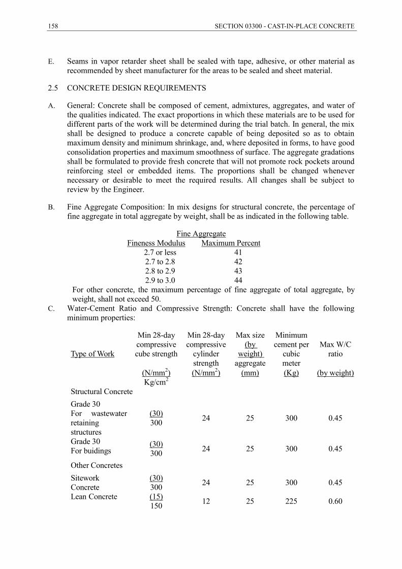
158 SECTION 03300 - CAST-IN-PLACE CONCRETE
E. Seams in vapor retarder sheet shall be sealed with tape, adhesive, or other material as
recommended by sheet manufacturer for the areas to be sealed and sheet material.
2.5 CONCRETE DESIGN REQUIREMENTS
A. General: Concrete shall be composed of cement, admixtures, aggregates, and water of the qualities indicated. The exact proportions in which these materials are to be used for different parts of the work will be determined during the trial batch. In general, the mix shall be designed to produce a concrete capable of being deposited so as to obtain maximum density and minimum shrinkage, and, where deposited in forms, to have good consolidation properties and maximum smoothness of surface. The aggregate gradations shall be formulated to provide fresh concrete that will not promote rock pockets around reinforcing steel or embedded items. The proportions shall be changed whenever necessary or desirable to meet the required results. All changes shall be subject to review by the Engineer.
B. Fine Aggregate Composition: In mix designs for structural concrete, the percentage of fine aggregate in total aggregate by weight, shall be as indicated in the following table.
Fine Aggregate Fineness Modulus Maximum Percent
2.7 or less 41 2.7 to 2.8 42 2.8 to 2.9 43 2.9 to 3.0 44
For other concrete, the maximum percentage of fine aggregate of total aggregate, by weight, shall not exceed 50.
C. Water-Cement Ratio and Compressive Strength: Concrete shall have the following minimum properties:
Type of Work
Min 28-day compressive cube strength
Min 28-day compressive
cylinder strength
Max size (by
weight) aggregate
Minimum cement per
cubic meter
Max W/C
ratio
(N/mm2) Kg/cm2
(N/mm2) (mm) (Kg) (by weight)
Structural Concrete Grade 30 For wastewater retaining structures
(30) 300 24 25 300 0.45
Grade 30 For buidings
(30) 300 24 25 300 0.45
Other Concretes Sitework Concrete
(30) 300 24 25 300 0.45
Lean Concrete (15) 150 12 25 225 0.60
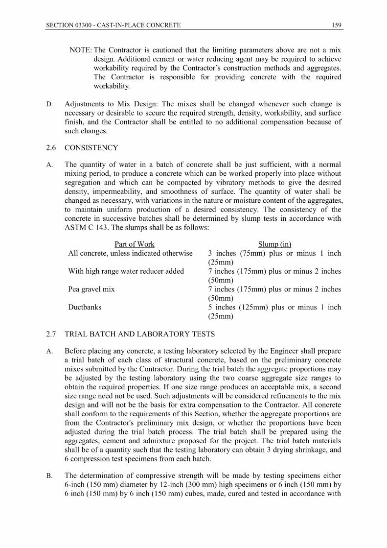
SECTION 03300 - CAST-IN-PLACE CONCRETE 159
NOTE: The Contractor is cautioned that the limiting parameters above are not a mix design. Additional cement or water reducing agent may be required to achieve workability required by the Contractor’s construction methods and aggregates. The Contractor is responsible for providing concrete with the required workability.
D. Adjustments to Mix Design: The mixes shall be changed whenever such change is
necessary or desirable to secure the required strength, density, workability, and surface finish, and the Contractor shall be entitled to no additional compensation because of such changes.
2.6 CONSISTENCY
A. The quantity of water in a batch of concrete shall be just sufficient, with a normal mixing period, to produce a concrete which can be worked properly into place without segregation and which can be compacted by vibratory methods to give the desired density, impermeability, and smoothness of surface. The quantity of water shall be changed as necessary, with variations in the nature or moisture content of the aggregates, to maintain uniform production of a desired consistency. The consistency of the concrete in successive batches shall be determined by slump tests in accordance with ASTM C 143. The slumps shall be as follows:
Part of Work Slump (in) All concrete, unless indicated otherwise 3 inches (75mm) plus or minus 1 inch
(25mm) With high range water reducer added 7 inches (175mm) plus or minus 2 inches
(50mm) Pea gravel mix 7 inches (175mm) plus or minus 2 inches
(50mm) Ductbanks 5 inches (125mm) plus or minus 1 inch
(25mm) 2.7 TRIAL BATCH AND LABORATORY TESTS
A. Before placing any concrete, a testing laboratory selected by the Engineer shall prepare a trial batch of each class of structural concrete, based on the preliminary concrete mixes submitted by the Contractor. During the trial batch the aggregate proportions may be adjusted by the testing laboratory using the two coarse aggregate size ranges to obtain the required properties. If one size range produces an acceptable mix, a second size range need not be used. Such adjustments will be considered refinements to the mix design and will not be the basis for extra compensation to the Contractor. All concrete shall conform to the requirements of this Section, whether the aggregate proportions are from the Contractor's preliminary mix design, or whether the proportions have been adjusted during the trial batch process. The trial batch shall be prepared using the aggregates, cement and admixture proposed for the project. The trial batch materials shall be of a quantity such that the testing laboratory can obtain 3 drying shrinkage, and 6 compression test specimens from each batch.
B. The determination of compressive strength will be made by testing specimens either 6-inch (150 mm) diameter by 12-inch (300 mm) high specimens or 6 inch (150 mm) by 6 inch (150 mm) by 6 inch (150 mm) cubes, made, cured and tested in accordance with

160 SECTION 03300 - CAST-IN-PLACE CONCRETE
ASTM C 192 and ASTM C 39. Three compression test specimens will be tested at 7 days and 3 at 28 days. The average compressive strength for the 3 specimens tested at 28 days for any given trial batch shall not be less than 125 percent of the specified compressive strength.
C. A sieve analysis of the combined aggregate for each trial batch shall be performed according to the requirements of ASTM C 136. Values shall be given for percent passing each sieve.
2.8 SHRINKAGE LIMITATION
A. The maximum concrete shrinkage for specimens cast in the laboratory from the trial batch, as measured at 21-day drying age or at 28-day drying age shall be 0.036 percent or 0.042 percent, respectively. Standard deviation will not be considered. The Contractor shall only use a mix design for construction that has first met the trial batch shrinkage requirements. Shrinkage limitations apply only to structural concrete.
B. The maximum concrete shrinkage for specimens cast in the field shall not exceed the trial batch maximum shrinkage requirement by more than 25 percent.
C. If the required shrinkage limitation is not met during construction, the Contractor shall take any or all of the following actions for securing the specified shrinkage requirements. These actions may include changing the source or aggregates, cement and/or admixtures; reducing water content; washing of aggregate to reduce fines; increasing the number of construction joints; modifying the curing requirements; or other actions designed to minimize shrinkage or the effects of shrinkage.
2.9 MEASUREMENT OF CEMENT AND AGGREGATE
A. The amount of cement and of each separate size of aggregate entering into each batch of concrete shall be determined by direct weighing equipment furnished by the Contractor and acceptable to the Engineer.
B. Weighing tolerances:
Material Percent of Total Weight
Cement 1
Aggregates 3
Admixtures 3 2.10 MEASUREMENT OF WATER
A. The quantity of water entering the mixer shall be measured by a suitable water meter or other measuring device of a type acceptable to the Engineer and capable of measuring the water in variable amounts within a tolerance of one percent. The water feed control mechanism shall be capable of being locked in position so as to deliver constantly any specified amount of water to each batch of concrete. A positive quick-acting valve shall be used for a cut-off in the water line to the mixer. The operating mechanism shall prevent leakage when the valves are closed.
SECTION 03300 - CAST-IN-PLACE CONCRETE 161
2.11 READY-MIXED CONCRETE
A. At the Contractor’s option, ready-mixed concrete may be used if it meets the requirements as to materials, batching, mixing, transporting, and placing as indicated herein and is in accordance with ASTM C 94, including the following supplementary requirements.
B. Ready-mixed concrete shall be delivered to the site of the work, and discharge shall be completed within one hour after the addition of the cement to the aggregates or before the drum has been revolved 250 revolutions, whichever is first.
C. Truck mixers shall be equipped with electrically-actuated counters by which the number of revolutions of the drum or blades may be readily verified. The counter shall be of the resetable, recording type, and shall be mounted in the driver's cab. The counters shall be actuated at the time of starting mixers at mixing speeds.
D. Each batch of concrete shall be mixed in a truck mixer for not less than 70 revolutions of the drum or blades at the rate of rotation designated by the manufacturer of equipment. Additional mixing, if any, shall be at the speed designated by the manufacturer of the equipment as agitating speed. All materials including mixing water shall be in the mixer drum before actuating the revolution counter for determining the number of revolution of mixing.
E. Truck mixers and their operation shall be such that the concrete throughout the mixed batch as discharged is within acceptable limits of uniformity with respect to consistency, mix, and grading. If slump tests taken at approximately the 1/4 and 3/4 points of the load during discharge give slumps differing by more than one inch when the required slump is 3 inches (75 mm) or less, or if they differ by more than 2 inches (50 mm) when the required slump is more than 3 inches (75 mm), the mixer shall not be used on the work unless the causing condition is corrected and satisfactory performance is verified by additional slump tests. All mechanical details of the mixer, such as water measuring and discharge apparatus, condition of the blades, speed of rotation, general mechanical condition of the unit, and clearance of the drum, shall be checked before a further attempt to use the unit will be permitted.
F. Each batch of ready-mixed concrete delivered at the job site shall be accompanied by a delivery ticket furnished to the Engineer in accordance with the Paragraph in Part 1 entitled "Delivery Tickets."
G. The use of non-agitating equipment for transporting ready-mixed concrete will not be permitted. Combination truck and trailer equipment for transporting ready-mixed concrete will not be permitted. The quality and quantity of materials used in ready-mixed concrete and in batch aggregates shall be subject to continuous inspection at the batching plant by the Engineer.
2.12 FLOOR HARDENER (SURFACE APPLIED)
A. Surface hardener shall be a light reflective non-oxidizing metallic aggregate dry shake material that is premeasured, premixed, and packaged at the factory. Surface hardener shall be applied at the rate of 1.8 to 2.5 lbs/ft2 (8.8-12 kg/m2).
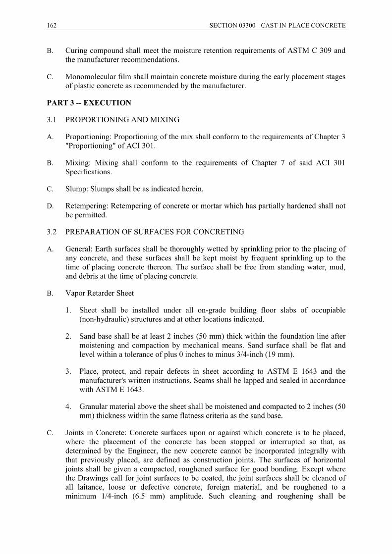
162 SECTION 03300 - CAST-IN-PLACE CONCRETE
B. Curing compound shall meet the moisture retention requirements of ASTM C 309 and the manufacturer recommendations.
C. Monomolecular film shall maintain concrete moisture during the early placement stages of plastic concrete as recommended by the manufacturer.
PART 3 -- EXECUTION
3.1 PROPORTIONING AND MIXING
A. Proportioning: Proportioning of the mix shall conform to the requirements of Chapter 3 "Proportioning" of ACI 301.
B. Mixing: Mixing shall conform to the requirements of Chapter 7 of said ACI 301 Specifications.
C. Slump: Slumps shall be as indicated herein.
D. Retempering: Retempering of concrete or mortar which has partially hardened shall not be permitted.
3.2 PREPARATION OF SURFACES FOR CONCRETING
A. General: Earth surfaces shall be thoroughly wetted by sprinkling prior to the placing of any concrete, and these surfaces shall be kept moist by frequent sprinkling up to the time of placing concrete thereon. The surface shall be free from standing water, mud, and debris at the time of placing concrete.
B. Vapor Retarder Sheet
1. Sheet shall be installed under all on-grade building floor slabs of occupiable (non-hydraulic) structures and at other locations indicated.
2. Sand base shall be at least 2 inches (50 mm) thick within the foundation line after moistening and compaction by mechanical means. Sand surface shall be flat and level within a tolerance of plus 0 inches to minus 3/4-inch (19 mm).
3. Place, protect, and repair defects in sheet according to ASTM E 1643 and the manufacturer's written instructions. Seams shall be lapped and sealed in accordance with ASTM E 1643.
4. Granular material above the sheet shall be moistened and compacted to 2 inches (50 mm) thickness within the same flatness criteria as the sand base.
C. Joints in Concrete: Concrete surfaces upon or against which concrete is to be placed, where the placement of the concrete has been stopped or interrupted so that, as determined by the Engineer, the new concrete cannot be incorporated integrally with that previously placed, are defined as construction joints. The surfaces of horizontal joints shall be given a compacted, roughened surface for good bonding. Except where the Drawings call for joint surfaces to be coated, the joint surfaces shall be cleaned of all laitance, loose or defective concrete, foreign material, and be roughened to a minimum 1/4-inch (6.5 mm) amplitude. Such cleaning and roughening shall be
SECTION 03300 - CAST-IN-PLACE CONCRETE 163
accomplished by hydroblasting or sandblasting (exposing aggregate) followed by thorough washing. All pools of water shall be removed from the surface of construction joints before the new concrete is placed.
D. After the surfaces have been prepared, all approximately horizontal construction joints shall be covered with a 6-inch (150 mm) lift of a pea gravel mix. The mix shall be placed and spread uniformly. Wall concrete shall follow immediately and shall be placed upon the fresh pea gravel mix.
E. Placing Interruptions: When placing of concrete is to be interrupted long enough for the concrete to take a set, the working face shall be given a shape by the use of forms or other means, that will secure proper union with subsequent work; provided that construction joints shall be made only where acceptable to the Engineer.
F. Embedded Items: No concrete shall be placed until all formwork, installation of parts to be embedded, reinforcement steel, and preparation of surfaces involved in the placing have been completed and accepted by the Engineer at least 4 hours before placement of concrete. All surfaces of forms and embedded items that have become encrusted with dried grout from previous work shall be cleaned before the surrounding or adjacent concrete is placed.
G. All inserts or other embedded items shall conform to the requirements herein.
H. All reinforcement, anchor bolts, sleeves, inserts, and similar items shall be set and secured in the forms at locations indicated on the Drawings or shown by shop drawings and shall be acceptable to the Engineer before any concrete is placed. Accuracy of placement is the responsibility of the Contractor.
I. Casting New Concrete Against Old: Where concrete is to be cast against old concrete (any concrete which is greater than 60 days of age), the surface of the old concrete shall be thoroughly cleaned and roughened by hydro-blasting or sandblasting (exposing aggregate). The joint surface shall be coated with an epoxy bonding agent unless indicated otherwise by the Engineer.
J. No concrete shall be placed in any structure until all water entering the space to be filled with concrete has been properly cut off or has been diverted by pipes, or other means, and carried out of the forms, clear of the WORK. No concrete shall be deposited underwater nor shall the Contractor allow still water to rise on any concrete until the concrete has attained its initial set. Water shall not be permitted to flow over the surface of any concrete in such manner and at such velocity as will injure the surface finish of the concrete. Pumping or other necessary dewatering operations for removing ground water, if required, shall be subject to the review of the Engineer.
K. Corrosion Protection: Pipe, conduit, dowels, and other ferrous items required to be embedded in concrete construction shall be so positioned and supported prior to placement of concrete that there will be a minimum of 2 inches (50 mm) clearance between said items and any part of the concrete reinforcement. Securing such items in position by wiring or welding them to the reinforcement will not be permitted.
L. Openings for pipes, inserts for pipe hangers and brackets, and anchors shall, where practicable, be provided during the placing of concrete.
164 SECTION 03300 - CAST-IN-PLACE CONCRETE
M. Anchor bolts shall be accurately set and shall be maintained in position by templates while being embedded in concrete.
N. Cleaning: The surfaces of all metalwork to be in contact with concrete shall be thoroughly cleaned of all dirt, grease, loose scale and rust, grout, mortar, and other foreign substances immediately before the concrete is placed.
3.3 HANDLING, TRANSPORTING, AND PLACING
A. General: Placing of concrete shall conform to the applicable requirements of Chapter 8 of ACI 301 and the requirements of this Section. No aluminum materials shall be used in conveying any concrete.
B. Non-Conforming Work or Materials: Concrete which during or before placing is found not to conform to the requirements indicated herein shall be rejected and immediately removed from the work. Concrete which is not placed in accordance with these Specifications or which is of inferior quality shall be removed and replaced.
C. Unauthorized Placement: No concrete shall be placed except in the presence of a duly authorized representative of the Engineer. The Contractor shall notify the Engineer in writing at least 24 hours in advance of placement of any concrete.
D. Placement in Wall and Column Forms: Concrete shall not be dropped through reinforcement steel or into any deep form, nor shall concrete be placed in any form in such a manner as to leave accumulation of mortar on the form surfaces above the placed concrete. In such cases, means such as hoppers and, if necessary, vertical ducts of canvas, rubber, or metal shall be used for placing concrete in the forms in a manner that it may reach the place of final deposit without separation. In no case shall the free fall of concrete exceed 4 feet (1.2 m) in walls and 8 feet (2.4 m) in columns below the ends of ducts, chutes, or buggies. Concrete shall be uniformly distributed during the process of depositing and in no case after depositing shall any portion be displaced in the forms more than 6 feet (1.8 m) in horizontal direction. Concrete in wall forms shall be deposited in uniform horizontal layers not deeper than 2 feet (0.61 m); and care shall be taken to avoid inclined layers or inclined construction joints except where such are required for sloping members. Each layer shall be placed while the previous layer is still soft. The rate of placing concrete in wall forms shall not exceed 5 feet (1.5 m) of vertical rise per hour. Sufficient illumination shall be provided in the interior of all forms so that the concrete at the places of deposit is visible from the deck or runway.
E. Casting New Concrete Against Old: Epoxy adhesive bonding agent shall be applied to the old surfaces according to the manufacturer's written recommendations. This provision shall not apply to joints where waterstop is provided. See Section 03290 - Joints in Concrete.
F. Conveyor Belts and Chutes: All ends of chutes, hopper gates, and all other points of concrete discharge throughout the Contractor's conveying, hoisting, and placing system shall be designed and arranged so that concrete passing from them will not fall separated into whatever receptacle immediately receives it. Conveyor belts, if used, shall be of a type acceptable to the Engineer. Chutes longer than 50 feet (15 m) will not be permitted. Minimum slopes of chutes shall be such that concrete of the indicated consistency will readily flow in them. If a conveyor belt is used, it shall be wiped clean
SECTION 03300 - CAST-IN-PLACE CONCRETE 165
by a device operated in such a manner that none of the mortar adhering to the belt will be wasted. All conveyor belts and chutes shall be covered.
G. Placement in Slabs: Concrete placed in sloping slabs shall proceed uniformly from the bottom of the slab to the top, for the full width of the placement. As the work progresses, the concrete shall be vibrated and carefully worked around the slab reinforcement, and the surface of the slab shall be screeded in an up-slope direction.
H. Temperature of Concrete: The temperature of concrete when it is being placed shall be not more than 90 degrees F (32 Deg C) nor less than 55 degrees F (13 Deg C) for sections less than 12 inches (300 mm) thick nor less than 50 degrees for all other sections. Concrete ingredients shall not be heated to a temperature higher than that necessary to keep the temperature of the mixed concrete, as placed, from falling below the minimum temperature. When the temperature of the concrete is 85 degrees F (29.4 Deg C) or above, the time between the introduction of the cement to the aggregates and discharge shall not exceed 45 minutes. If concrete is placed when the weather is such that the temperature of the concrete would exceed 90 degrees F(32 Deg C), the Contractor shall employ effective means, such as precooling of aggregates and mixing water using ice or placing at night, as necessary to maintain the temperature of the concrete, as it is placed, below 90 degrees F (32 Deg C). The Contractor shall be entitled to no additional compensation on account of the foregoing requirements.
I. Cold Weather Placement:
1. Placement of concrete shall conform to ACI 306.1 - Cold Weather Concreting, and the following.
2. Remove all snow, ice, and frost from the surfaces, including reinforcement, against which concrete is to be placed. Before beginning concrete placement, thaw the subgrade to a minimum depth of 6 inches (150 m). All reinforcement and embedded items shall be warmed to above 32 degrees F (0 Deg C) prior to concrete placement.
3. Maintain the concrete temperature above 50 degrees F (10 Deg C) for at least 3 days after placement.
3.4 PUMPING OF CONCRETE
A. General: If the pumped concrete does not produce satisfactory end results, the Contractor shall discontinue the pumping operation and proceed with the placing of concrete using conventional methods.
B. Pumping Equipment: The pumping equipment shall have 2 cylinders and be designed to operate with one cylinder in case the other one is not functioning. In lieu of this requirement, the Contractor may have a standby pump on the site during pumping.
C. The minimum diameter of the hose conduits shall be in accordance with ACI 304.2R.
D. Pumping equipment and hose conduits that are not functioning properly shall be replaced.
E. Aluminum conduits for conveying the concrete shall not be permitted.
166 SECTION 03300 - CAST-IN-PLACE CONCRETE
F. Field Control: Concrete samples for slump, air content, and test specimens will be taken at the placement end of the hose.
3.5 ORDER OF PLACING CONCRETE
A. The order of placing concrete in all parts of the WORK shall be acceptable to the Engineer. In order to minimize the effects of shrinkage, the concrete shall be placed in units as bounded by construction joints at the indicated locations. The placing of units shall be done by placing alternate units in a manner such that each unit placed shall have cured at least 5 days for hydraulic structures and 2 days for all other structures before the contiguous unit or units are placed, except that the corner sections of vertical walls shall not be placed until the 2 adjacent wall panels have cured at least 10 days for hydraulic structures and 4 days for all other structures.
B. The surface of the concrete shall be level whenever a run of concrete is stopped. To insure a level, straight joint on the exposed surface of walls, a wood strip at least 3/4-inch (19 mm) thick shall be tacked to the forms on these surfaces. The concrete shall be carried about 1/2-inch (12 mm) above the underside of the strip. About one hour after the concrete is placed, the strip shall be removed and any irregularities in the edge formed by the strip shall be leveled with a trowel and all laitance shall be removed.
3.6 TAMPING AND VIBRATING
A. As concrete is placed in the forms or in excavations, it shall be thoroughly settled and compacted, throughout the entire depth of the layer which is being consolidated, into a dense, homogeneous mass, filling all corners and angles, thoroughly embedding the reinforcement, eliminating rock pockets, and bringing only a slight excess of water to the exposed surface of concrete. Vibrators shall be Group 3 per ACI 309, high speed power vibrators (8000 to 12,000 rpm) of an immersion type in sufficient number and with at least one standby unit as required. Group 2 vibrators may be used only at specific locations when accepted by the Engineer.
B. Care shall be used in placing concrete around waterstops. The concrete shall be carefully worked by rodding and vibrating to make sure that all air and rock pockets have been eliminated. Where flat-strip type waterstops are placed horizontally, the concrete shall be worked under the waterstops by hand, making sure that all air and rock pockets have been eliminated. Concrete surrounding the waterstops shall be given additional vibration over and above that used for adjacent concrete placement to assure complete embedment of the waterstops in the concrete.
C. Concrete in walls shall be internally vibrated and at the same time rammed, stirred, or worked with suitable appliances, tamping bars, shovels, or forked tools until it completely fills the forms or excavations and closes snugly against all surfaces. Subsequent layers of concrete shall not be placed until the layers previously placed have been worked thoroughly. Vibrators shall be provided in sufficient numbers, with standby units as required, to accomplish the required results within 15 minutes after concrete of the prescribed consistency is placed in the forms. The vibrating head shall not contact the surfaces of the forms. Care shall be taken not to vibrate concrete excessively or to work it in any manner that causes segregation of its constituents.

SECTION 03300 - CAST-IN-PLACE CONCRETE 167
3.7 FINISHING CONCRETE SURFACES
A. General: Surfaces shall be free from fins, bulges, ridges, offsets, honeycombing, or roughness of any kind, and shall present a finished, smooth, continuous hard surface. Allowable deviations from plumb or level and from the alignment, profiles, and dimensions shown are defined as tolerances and are indicated in Part 1, above. These tolerances are to be distinguished from irregularities in finish as described herein. Aluminum finishing tools shall not be used.
B. Formed Surfaces: No treatment is required after form removal except for curing, repair of defective concrete, and treatment of surface defects. Where architectural finish is required, it shall be as indicated.
C. Unformed Surfaces: After proper and adequate vibration and tamping, all unformed top surfaces of slabs, floors, walls, and curbs shall be brought to a uniform surface with suitable tools. Immediately after the concrete has been screeded, it shall be treated with a liquid evaporation retardant. The retardant shall be used again after each work operation as necessary to prevent drying shrinkage cracks. The classes of finish specified for unformed concrete surfaces are designated and defined as follows:
1. Finish U1 - Sufficient leveling and screeding to produce an even, uniform surface with surface irregularities not to exceed 3/8-inch (10 mm). No further special finish is required.
2. Finish U2 - After sufficient stiffening of the screeded concrete, surfaces shall be float finished with wood or metal floats or with a finishing machine using float blades. Excessive floating of surfaces while the concrete is plastic and dusting of dry cement and sand on the concrete surface to absorb excess moisture will not be permitted. Floating shall be the minimum necessary to produce a surface that is free from screed marks and is uniform in texture. Surface irregularities shall not exceed 1/4-inch (6.4 mm). Joints and edges shall be tooled where indicated or as determined by the Engineer.
3. Finish U3 - After the finish U2 surface has hardened sufficiently to prevent excess of fine material from being drawn to the surface, steel troweling shall be performed with firm pressure such as will flatten the sandy texture of the floated surface and produce a dense, uniform surface free from blemishes, ripples, and trowel marks. The finish shall be smooth and free of all irregularities.
4. Finish U4 - Trowel the Finish U3 surface to remove local depressions or high points. In addition, the surface shall be given a light hairbroom finish with brooming perpendicular to drainage unless otherwise indicated. The resulting surface shall be rough enough to provide a nonskid finish.
D. Unformed surfaces shall be finished according to the following schedule:
UNFORMED SURFACE FINISH SCHEDULE
Area Finish Grade slabs and foundations to be covered with concrete or fill material U1 Floors to be covered with grouted tile or topping grout U2 Water bearing slabs with slopes 10 percent and less U3
168 SECTION 03300 - CAST-IN-PLACE CONCRETE
Water bearing slabs with slopes greater than 10 percent U4 Slabs not water bearing U4 Slabs to be covered with built-up roofing U2 Interior slabs and floors to receive architectural finish U3 Top surface of walls U3
E. Floor Hardener (Surface Applied)
1. The following additional requirements apply to the substrate concrete in areas indicated to be under floor hardener:
a. Slump shall be no greater than 4 inches (100 mm) when peak ambient temperatures are expected to exceed 65 degrees F (18 Deg C) and no greater than 3 inches (75 mm) when temperatures will not exceed 65 degrees F (18 Deg C).
b. Air content shall not exceed 3 percent.
c. No calcium chloride or set accelerating admixture containing calcium chloride shall be used.
d. Do not use admixtures that increase bleeding.
e. Do not use fly ash.
2. The Contractor shall finish areas indicated to receive hardener in conformance with the manufacturer's recommendations and the following. After leveling the concrete surface and as soon as the concrete will support an operator and machine without disturbing the level or working up excessive fines, the Contractor shall float the surface of the slab with a mechanical float fitted with detachable float shoes. Then apply 1/2 to 2/3 of the total amount of dry shake surface hardener uniformly to the surface. A mechanical spreader is recommended. Float the surface once the shake has absorbed sufficient moisture, as indicated by darkening of the shake. Immediately apply the remainder of the shake and allow it to absorb moisture. Do not apply shake when bleed water is present.
3. Perform a third floating if time and setting characteristics of the concrete will allow, but do not add water to the surface.
4. As the surface stiffens further and loses sheen, trowel with blades set relatively flat, using hand or mechanical methods. Remove all marks and pinholes in a final raised trowel operation.
5. Cure the finished surface using the fill-forming curing compound recommended by the manufacturer at a coverage rate which will provide moisture retention in excess of the requirements of ASTM C 309. Maintain ambient temperatures above 50 degrees F (10 Deg C) during the curing period.
6. Keep floors covered and prohibit traffic and loads for 10 days minimum after completion.

SECTION 03300 - CAST-IN-PLACE CONCRETE 169
3.8 ARCHITECTURAL FINISH
A. General: Architectural finishes shall be provided only where specifically indicated on the Drawings. In all other locations, the paragraph entitled Finishing Concrete Surfaces, shall apply.
1. Immediately after the forms have been stripped, the concrete surface shall be inspected and any poor joints, voids, rock pockets, or other defective areas shall be repaired and all form-tie holes filled as indicated herein.
2. Architectural finishes shall not be applied until the concrete surface has been repaired as required and the concrete has cured at least 14 days.
3. All architecturally treated concrete surfaces shall conform to the accepted sample in texture, color, and quality. It shall be the Contractor's responsibility to maintain and protect the concrete finish.
B. Smooth Concrete Finish
1. The concrete surface shall be wetted, and a grout shall be applied with a brush. The grout shall be made by mixing one part portland cement and one part of fine sand that will pass a No. 16 sieve with sufficient water to give it the consistency of thick paint. The cement used in said grout shall be 1/2 gray and 1/2 white portland cement, or other proportion as determined by the Engineer. cement shall be Calcium chloride at 5 percent by volume of the cement shall be used in the brush coat. The freshly applied grout shall be vigorously rubbed into the concrete surface with a wood float filling all small air holes. After all the surface grout had been removed with a steel trowel, the surface shall be allowed to dry and, when dry, shall be vigorously rubbed with burlap to remove completely all surface grout so that there is no visible paint-like film of grout on the concrete. The entire cleaning operation for any area shall be completed the day it is started, and no grout shall be left on the surface overnight.
2. Cleaning operations for any given day shall be terminated at panel joints. It is required that the various operations be carefully timed to secure the desired effect which is a light-colored concrete surface of uniform color and texture without any appearance of a paint or grout film.
3. In the event that improper manipulation results in an inferior finish, the Contractor shall rub such inferior areas with carborundum bricks.
4. Before beginning any of the final treatment on exposed surfaces, the Contractor shall treat in a satisfactory manner a trial area of at least 200 square feet (20 m2) in some inconspicuous place selected by the Engineer and shall preserve said trial area undisturbed until the completion of the job.
C. Sandblasted Concrete Finish
1. Sandblasting shall be done in a safe manner acceptable to local authorities. The sandblasting shall be a light sandblast to remove laitance and to produce a uniform fine aggregate surface texture with approximately 1/32 to 1/16-inch (0.8 mm to 1.6
170 SECTION 03300 - CAST-IN-PLACE CONCRETE
mm) of surface sandblasted off. Corners, patches, form panel joints, and soft spots shall be sandblasted with care.
2. A 3-sq ft (0.3 m2) sample panel of the sandblasted finish shall be provided by the Contractor for acceptance by the Engineer prior to starting the sandblasting work. The sample panel shall include a corner, plugs, and joints and shall be marked after approval. All other sandblasting shall be equal in finish to the sample panel.
3. Protection against sandblasting shall be provided on all adjacent surfaces and materials not requiring sandblasting. After sandblasting, the concrete surfaces shall be washed with clean water and excess sand removed.
3.9 CURING AND DAMPPROOFING
A. General: All concrete shall be cured for not less than 7 days after placing, in accordance with the methods indicated below for the different parts of the WORK.
Surface to be Cured or Dampproofed Method Unstripped forms 1 Wall sections with forms removed 6 Construction joints between footings and walls, and between floor slab and columns
2
Encasement concrete and thrust blocks 3 All concrete surfaces not specifically indicated in this Paragraph 4 Floor slabs on grade in hydraulic structures 5 Slabs not on grade 6
B. Method 1: Wooden forms shall be wetted immediately after concrete has been placed
and shall be kept wet with water until removal. If steel forms are used the exposed concrete surfaces shall be kept continuously wet until the forms are removed. If forms are removed within 7 days of placing the concrete, curing shall be continued in accordance with Method 6 below.
C. Method 2: The surface shall be covered with burlap mats which shall be kept wet with water for the duration of the curing period, until the concrete in the walls has been placed. No curing compound shall be applied to surfaces cured under Method 2.
D. Method 3: The surface shall be covered with moist earth not less than 4 hours nor more than 24 hours after the concrete is placed. Earthwork operations that may damage the concrete shall not begin until at least 7 days after placement of concrete.
E. Method 4: The surface shall be sprayed with a liquid curing compound.
1. It shall be applied in accordance with the manufacturer's printed instructions at a maximum coverage rate of 200 square feet per gallon (5m2/litre) and in such a manner as to cover the surface with a uniform film which will seal thoroughly.
2. Where the curing compound method is used, care shall be exercised to avoid damage to the seal during the 7-day curing period. If the seal is damaged or broken before the expiration of the curing period, the break shall be repaired immediately by the application of additional curing compound over the damaged portion.
SECTION 03300 - CAST-IN-PLACE CONCRETE 171
3. Wherever curing compound has been applied by mistake to surfaces against which concrete subsequently is to be placed and to which it is to adhere, compound shall be entirely removed by wet sandblasting just prior to the placing of new concrete.
4. Curing compound shall be applied as soon as the concrete has hardened enough to prevent marring on unformed surfaces and within 2 hours after removal of forms. Repairs to formed surfaces shall be made within the 2-hour period; provided, however, that any such repairs which cannot be made within the said 2-hour period shall be delayed until after the curing compound has been applied. When repairs are to be made to an area on which curing compound has been applied, the area involved shall first be wet-sandblasted to remove the curing compound.
5. At all locations where concrete is placed adjacent to a panel which has been coated with curing compound, the panel shall have curing compound reapplied to an area within 6 feet (1.8 m) of the joint and to any other location where the curing membrane has been disturbed.
6. Prior to final acceptance of the WORK, all visible traces of curing compound shall be removed from all surfaces in such a manner that does not damage the surface finish.
F. Method 5:
1. Until the concrete surface is covered with curing compound, the entire surface shall be kept damp by applying water using nozzles that atomize the flow so that the surface is not marred or washed. The concrete shall be given a coat of curing compound in accordance with Method 4 above. Not less than one hour nor more than 4 hours after the curing compound has been applied, the surface shall be wetted with water delivered through a fog nozzle, and concrete-curing blankets shall be placed on the slabs. The curing blankets shall be polyethylene sheet, polyethylene-coated waterproof paper sheeting, or polyethylene-coated burlap. The blankets shall be laid with the edges butted together and with the joints between strips sealed with 2-inch (50 mm) wide strips of sealing tape or with edges lapped not less than 3 inches (75 mm) and fastened together with a waterproof cement to form a continuous watertight joint.
2. The curing blankets shall be left in place during the 7-day curing period and shall not be removed until after concrete for adjacent work has been placed. If the curing blankets become torn or otherwise ineffective, the Contractor shall replace damaged sections. During the first 3 days of the curing period, no traffic of any nature and no depositing, temporary or otherwise, of any materials shall be permitted on the curing blankets. During the remainder of the curing period, foot traffic and temporary depositing of materials that impose light pressure will be permitted only on top of plywood sheets 5/8-inch(16mm) minimum thickness, laid over the curing blanket. The Contractor shall add water under the curing blanket as often as necessary to maintain damp concrete surfaces at all times.
G. Method 6: This method applies to both walls and slabs.
172 SECTION 03300 - CAST-IN-PLACE CONCRETE
1. The concrete shall be kept continuously wet by the application of water for a minimum period of at least 7 consecutive days beginning immediately after the concrete has reached final set or forms have been removed.
2. Until the concrete surface is covered with the curing medium, the entire surface shall be kept damp by applying water using nozzles that atomize the flow so that the surface is not marred or washed.
3. Heavy curing mats shall be used as a curing medium to retain the moisture during the curing period. The curing medium shall be weighted or otherwise held substantially in contact with the concrete surface to prevent being dislodged by wind or any other causes. All edges shall be continuously held in place.
4. The curing blankets and concrete shall be kept continuously wet by the use of sprinklers or other means both during and after normal working hours.
5. Immediately after the application of water has terminated at the end of the curing period, the curing medium shall be removed, any dry spots shall be rewetted, and curing compound shall be immediately applied in accordance with Method 4 above.
6. The Contractor shall dispose of excess water from the curing operation to avoid damage to the work.
H. Dampproofing
1. The exterior surface of all buried roof slabs shall be dampproofed as follows.
2. Immediately after completion of curing the surface shall be sprayed with a dampproofing agent consisting of an asphalt emulsion. Application shall be in 2 coats. The first coat shall be diluted to strength by the addition of water and shall be sprayed on so as to provide a maximum coverage rate of 2.5 m2/litre The second coat shall consist of an application of the undiluted material, and shall be sprayed on so as to provide a maximum coverage rate of 100 square feet per gallon (2.5 m2/litre). Dampproofing material shall be as indicated above.
3. As soon as the material has taken an initial set, the entire area thus coated shall be coated with whitewash. Any formula for mixing the whitewash may be used if it produces a uniformly coated white surface and remains until placing of the backfill. If the whitewash fails to remain on the surface until the backfill is placed, the Contractor shall apply additional whitewash.
3.10 PROTECTION
A. The Contractor shall protect all concrete against injury until final acceptance.
B. Fresh concrete shall be protected from damage due to rain, hail, sleet, or snow. The Contractor shall provide such protection while the concrete is still plastic and whenever precipitation is imminent or occurring.
SECTION 03300 - CAST-IN-PLACE CONCRETE 173
3.11 CURING IN COLD WEATHER
A. Water curing of concrete may be reduced to 6 days during periods when the mean daily temperature in the vicinity of the Site is less than 40 degrees F (5 Deg C); provided that, during the prescribed period of water curing, when temperatures are such that concrete surfaces may freeze, water curing shall be temporarily discontinued.
B. Concrete cured by an application of curing compound will require no additional protection from freezing if the protection at 50 degrees F (10 Deg C) for 72 hours is obtained by means of approved insulation in contact with the forms or concrete surfaces; otherwise the concrete shall be protected against freezing temperatures for 72 hours immediately following 72 hours protection at 50 degrees F (10 Deg C). Concrete cured by water shall be protected against freezing temperatures for 3 days immediately following the 72 hours of protection at 50 degrees F (10 Deg C).
C. Discontinuance of protection against freezing temperatures shall be such that the drop in temperature of any portion of the concrete will be gradual and will not exceed 40 degrees F (5 Deg C) in 24 hours. In the spring, when the mean daily temperature rises above 40 degrees F (5 Deg C) for more than 3 successive days, the specified 72-hour protection at a temperature not lower than 50 degrees F (10 Deg C) may be discontinued for as long as the mean daily temperature remains above 40 degrees F (5 Deg C); provided, that the concrete shall be protected against freezing temperatures for not less than 48 hours after placement.
D. Where artificial heat is employed, special care shall be taken to prevent the concrete from drying. Use of unvented heaters will be permitted only when unformed surfaces of concrete adjacent to the heaters are protected for the first 24 hours from an excessive carbon dioxide atmosphere by application of curing compound; provided, that the use of curing compound for such surfaces is otherwise permitted by these Specifications.
3.12 TREATMENT OF SURFACE DEFECTS
A. As soon as forms are removed, all exposed surfaces shall be carefully examined and any irregularities shall be immediately rubbed or ground in a satisfactory manner in order to secure a smooth, uniform, and continuous surface. Plastering or coating of surfaces to be smoothed will not be permitted. No repairs shall be made until after inspection by the Engineer. In no case will extensive patching of honeycombed concrete be permitted. Concrete containing minor voids, holes, honeycombing, or similar depression defects shall be repaired as indicated below. Concrete containing extensive voids, holes, honeycombing, or similar depression defects shall be completely removed and replaced. Repairs and replacements shall be performed promptly.
B. Defective surfaces to be repaired shall be cut back from trueline a minimum depth of 1/2-inch over the entire area. Feathered edges will not be permitted. Where chipping or cutting tools are not required in order to deepen the area properly, the surface shall be prepared for bonding by the removal of all laitance or soft material, plus not less than 1/32-inch (0.8 mm) depth of the surface film from all hard portions by means of an efficient sandblast. After cutting and sandblasting, the surface shall be wetted sufficiently in advance of shooting with shotcrete or with cement mortar so that while the repair material is being applied, the surfaces underneath will remain moist but not so wet as to overcome the suction upon which a good bond depends. The material used for
174 SECTION 03300 - CAST-IN-PLACE CONCRETE
repair proposed shall consist of a mixture of one sack of cement to 3 cubic feet (0.1 m3) of sand. For exposed walls, the cement shall contain such a proportion of Atlas white portland cement as is required to make the color of the patch match the color of the surrounding concrete.
C. Holes left by tie-rod cones shall be reamed with suitable toothed reamers so as to leave the surfaces of the holes clean and rough. Holes then shall be repaired in an approved manner with dry-packed cement grout. Holes left by form-tying devices having a rectangular cross-section and other imperfections having a depth greater than their least surface dimension shall not be reamed but shall be repaired in an approved manner with dry-packed cement grout.
D. All repairs shall be built up and shaped in such a manner that the completed work will conform to the requirements of this Section, as applicable, using approved methods which will not disturb the bond, cause sagging, or cause horizontal fractures. Surfaces of repairs shall receive the same kind and amount of curing treatment as required for the concrete in the repaired section.
E. Prior to filling any structure with water, all cracks that may have developed shall be "vee'd" as indicated and filled with sealant conforming to the requirements of Section 03290 - Joints in Concrete. This repair method shall be done on the water bearing face of members. Prior to backfilling, faces of members in contact with fill which are not covered with a waterproofing membrane shall also have cracks repaired as indicated herein.
3.13 PATCHING HOLES IN CONCRETE
A. Patching Small Holes:
1. Holes which are less than 12 inches (300 mm) in the least dimension and extend completely through concrete members shall be filled.
2. Small holes in members which are water-bearing or in contact with soil or other fill material shall be filled with non-shrink grout. Where a face of the member is exposed to view, the non-shrink grout shall be held back 2 inches (50 mm) from the finished surface. The remaining 2 inches (50 mm) shall then be patched according to the Paragraph entitled "Treatment of Surface Defects."
3. Small holes through all other concrete members shall be filled with non-shrink grout, with exposed faces treated as above.
B. Patching Large Holes:
1. Holes which are larger than 12 inches (300 mm) in the least dimension shall have a keyway chipped into the edge of the opening all around, unless a formed keyway exists. The holes shall then be filled with concrete as indicated herein.
2. Holes which are larger than 24 inches (600 mm) in the least dimension and which do not have reinforcing steel extending from the existing concrete, shall have reinforcing steel set in grout in drilled holes. The reinforcing added shall match the reinforcing in the existing wall unless indicated otherwise.
SECTION 03300 - CAST-IN-PLACE CONCRETE 175
3. Large holes in members which are water bearing or in contact with soil or other fill shall have a bentonite type waterstop material placed around the perimeter of the hole in accordance with Section 03290 - Joints in Concrete, unless there is an existing waterstop in place.
3.14 CARE AND REPAIR OF CONCRETE
A. The Contractor shall protect all concrete against injury or damage from excessive heat, lack of moisture, overstress, or any other cause until final acceptance. Particular care shall be taken to prevent the drying of concrete and to avoid roughening or otherwise damaging the surface. Any concrete found to be damaged, or which may have been originally defective, or which becomes defective at any time prior to the final acceptance of the completed WORK, or which departs from the established line or grade, or which, for any other reason, does not conform to the requirements of the Contract Documents, shall be satisfactorily repaired or removed and replaced with acceptable concrete.
- END OF SECTION -

176 SECTION 03315 - GROUT
SECTION 03315 - GROUT
PART 1 -- GENERAL
1.1 THE REQUIREMENT
A. The Contractor shall provide grout, complete and in place, in accordance with the Contract Documents.
B. The following types of grout are covered in this Section:
1. Non-Shrink Grout: This type of grout shall be used wherever grout is indicated, unless another type is specifically referenced.
2. Cement Grout
3. Epoxy Grout
4. Topping Grout and Concrete Fill
1.2 REFERENCE SPECIFICATIONS, CODES, AND STANDARDS
A. Specifications, codes, and standards shall be as listed in Section 03300 - Cast-in-Place Concrete, and as indicated herein.
1.3 CONTRACTOR SUBMITTALS
A. Furnish submittals in accordance with Section 01300 - Contractor Submittals
B. Shop Drawings: Include certified test results verifying compliance with the compressive strength, shrinkage, and expansion requirements; and manufacturer's literature containing instructions and recommendations on the mixing, handling, placement, and appropriate uses for each proposed type of non-shrink and epoxy grout.
C. Provide manufacturer’s independent certification of ASTM C 1107 - Packaged Dry, Hydraulic-Cement Grout (Nonshrink), compliance without modification of the standard methods certifying that the Class B or C grout post hardening non-shrink properties are not based on gas expansion, grouts have strengths of 246 kg/cm2 at 1 day, 460 kg/cm2 at 3 days and 530 kg/cm2 at 28 days when cured at 22 degrees C as well as meeting the 3,7, and 28 day strengths when tested and cured at the 7 degree C and 35 degree C limits and all other requirements of ASTM C 1107.
D. The Contractor shall engage an independent testing laboratory to run a 24 hour grout evaluation in accordance with ASTM C 1107 of each grout submitted for approval showing compliance to all aspects of the evaluation and submit results to the Engineer for review.
1.4 QUALITY ASSURANCE
A. Field Tests:
1. Compression test specimens will be taken during construction from the first placement of each type of grout and at intervals thereafter selected by the Engineer
SECTION 03315 - GROUT 177
to insure continued compliance with these specifications. The specimens will be made by the Engineer or its representative.
2. Compression tests and fabrication of specimens for cement grout and non-shrink grout will be performed in accordance with ASTM C 109 - Test Method for Compressive Strength of Hydraulic Cement Mortars (Using 2-in or 50-mm Cube Specimens) at intervals during construction selected by the Engineer. A set of three specimens will be made for testing at 7 days, 28 days, and each additional time period as appropriate.
3. Compression tests and fabrication of specimens for epoxy grout will be performed in accordance with ASTM C 579 - Test Methods for Compressive Strength of Chemical-Resistant Mortars and Monolithic Surfacings, Method B, at intervals during construction selected by the Engineer. A set of three specimens will be made for testing at 7 days, and each earlier time period as appropriate.
4. All grout which fails to meet requirements is subject to removal and replacement.
5. The cost of laboratory tests on grout will be paid by the Contractor.
B. Construction Tolerances: Construction tolerances shall be in accordance with Section 03300- Cast-In-Place Concrete, unless indicated otherwise.
PART 2 -- PRODUCTS
2.1 CEMENT GROUT
A. Cement Grout: Cement grout shall be composed of one part cement, three parts sand, and the minimum amount of water necessary to obtain the desired consistency. Where needed to match the color of adjacent concrete, white Portland cement shall be blended with regular cement as needed. The minimum compressive strength at 28 days shall be 280 kg/cm2.
B. Cement grout materials shall be as indicated in Section 03300- Cast-In-Place Concrete, except that no cement from kilns burning metal-rich hazardous waste fuel shall be used.
2.2 PREPACKAGED GROUTS
A. Non-Shrink Grout:
1. Non-shrink grout shall be a prepackaged, inorganic, non-gas-liberating, non-metallic, cement-based grout requiring only the addition of water. Cement from kilns burning metal-rich hazardous waste fuel shall not be used. Manufacturer's instructions shall be printed on each bag or other container in which the materials are packaged. The specific formulation for each class of non-shrink grout herein shall be that recommended by the manufacturer for the particular application. All grouts (Grade A, B, C) shall be tested for height change of the hardened grout at 1, 3, 14, and 28 days in accordance with ASTM C 1090 - Test Method for Measuring Change in Height of Cylindrical Specimens for Hydraulic-Cement Grout, and shall be tested for compression at 1, 3, 7, and 28 days in accordance with the modified ASTM C 109 testing procedure.
178 SECTION 03315 - GROUT
2. Class A non-shrink grouts shall have a minimum 28 day compressive strength of 34474 kpa and shall meet the requirements of ASTM C 1107 when mixed to a flowable, plastic, or stiff consistency. When tested in accordance with ASTM C 1090, grout shall have a maximum of 4.0 percent expansion in the pre-hardened state.
3. Class B or C high precision, fluid, extended working time, non-shrink grouts shall have a minimum 28 day compressive strength of 530 kg/cm2; shall have no shrinkage (0.0 percent) and a maximum 4.0 percent expansion in the plastic state when tested in accordance with ASTM C 827 - Test Method for Early Volume Change of Cementitious Mixtures; and shall have no shrinkage (0.0 percent) and a maximum of 0.2 percent expansion in the hardened state; and when mixed to a fluid consistency of 20 to 30 seconds per ASTM C 939 at temperature extremes of 7 to 32 degrees C shall have an extended working time of 30 minutes when tested in accordance with ASTM C 1107. It shall be the Contractor’s responsibility to demonstrate equivalency of locally available substitute products made outside of the United States.
4. Application:
a. Class A non-shrink grout shall be used for the repair of holes and defects in concrete members which are not water-bearing and not in contact with soil or other fill material, and grouting railing posts in place.
b. Class B or C non-shrink grout shall be used for the repair of holes and defects in concrete members which are water bearing or in contact with soil or other fill material, grouting under all base plates for structural steel members, grouting under all equipment base plates, and at all locations where grout is required by the Contract Documents except where epoxy grout is specifically required. Class B or C non-shrink grout may be used in place of Class A non-shrink grout for all applications. Class B or C non-shrink grout shall not be used for dry packing applications.
B. Epoxy Grout:
1. Epoxy grout shall be a pourable, non-shrink, 100 percent solids system. The epoxy grout system shall have three components: resin, hardener, and specially blended aggregate, all premeasured and prepackaged. The resin component shall not contain any non-reactive diluents. Variation of component ratios is not permitted unless specifically recommended by the manufacturer. Manufacturer's instructions shall be printed on each container in which the materials are packaged.
2. The chemical formulation of the epoxy grout shall be that recommended by the manufacturer for the particular application.
3. The mixed epoxy grout system shall have a minimum working life of 90 to 120 minutes at 21 degrees C.
4. The epoxy grout shall develop a compressive strength of 62053 kpa in 24 hours and 915 kg/cm2 in seven days when tested in accordance with ASTM C 579, Method B.
SECTION 03315 - GROUT 179
There shall be no shrinkage (0.0 percent) and a maximum 4.0 percent expansion when tested in accordance with ASTM C 827.
5. The epoxy grout shall exhibit a minimum effective bearing area of 90 percent. This shall be determined by testing in accordance with ASTM C 1339 - Standard Test Method for Flowability and Bearing Area of Chemical-Resistant Polymer Machinery Grouts, for bearing area and flow.
6. Application: Epoxy grout shall be used to embed all anchor bolts and reinforcing steel required to be set in grout, and for other applications specifically required in the Contract Documents.
2.3 TOPPING GROUT AND CONCRETE FILL
A. Grout for topping of slabs and concrete fill for built-up surfaces of tank, channel, and basin bottoms shall be composed of cement, fine aggregate, coarse aggregate, water, and admixtures. All materials and procedures for concrete in Section 03300- Cast-In-Place Concrete shall apply except as noted otherwise herein.
B. Topping grout and concrete fill shall contain a minimum of 335 kg of cement per cubic meter with a maximum water cement ratio of 0.45. Where concrete fill is thicker than 75 mm, sitework concrete in accordance with Section 03300- Cast-In-Place Concrete may be used if accepted by the Engineer.
C. Coarse aggregate shall be graded as follows:
U.S. STANDARD PERCENT BY SIEVE SIZE WEIGHT PASSING 1/2" 100 3/8" 90-100 No. 4 20-55 No. 8 5-30 No. 16 0-10 No. 30 0
D. Final mix design shall be determined by trial mix design under supervision of the
approved testing laboratory.
E. Strength: Minimum compressive strength of topping grout and concrete fill at the end of 28 days shall be 210 kg/cm2.
2.4 CURING MATERIALS
A. Curing materials shall be in accordance with Section 03300- Cast-In-Place Concrete for cement grout and be as recommended by the manufacturer of prepackaged grouts.
2.5 CONSISTENCY
A. The consistency of grout shall be as necessary to completely fill the space to be grouted for the particular application. Dry pack consistency is such that the grout is plastic and moldable but will not flow. Where "dry pack" is required by the Contract Documents, it
180 SECTION 03315 - GROUT
shall mean a grout of that consistency; the type of grout to be used shall be as indicated herein for the particular application.
B. The slump for topping grout and concrete fill shall be adjusted to match placement and finishing conditions but shall not exceed 100 mm.
2.6 MEASUREMENT OF INGREDIENTS
A. Measurements for cement grout shall be made accurately by volume using containers. Shovel measurement shall not be allowed.
B. Prepackaged grouts shall have ingredients measured by means recommended by the manufacturer.
PART 3 -- EXECUTION
3.1 GENERAL
A. Surface preparation, curing, and protection of cement grout shall be in accordance with Section 03300- Cast-In-Place Concrete. The finish of the grout surface shall match that of the adjacent concrete unless otherwise indicated.
B. The manufacturer of Class B or C non-shrink grout and epoxy grout shall provide on-Site technical assistance upon request at no cost to the Employer.
C. Base concrete or masonry shall have attained its design strength before grout is placed, unless authorized by the Engineer.
3.2 GROUTING PROCEDURES
A. Prepackage Grouts: Mixing, surface preparation, handling, placing, consolidation, curing, and other means of execution for prepackaged grouts shall be done according to the instructions and recommendations of the manufacturer.
B. Base Plate Grouting:
1. For base plates, the original concrete shall be blocked out or finished off a sufficient distance below the plate to provide for a one-inch thickness of grout or a thickness as indicated on the Drawings.
2. After the base plate has been set in position at the proper elevation by steel wedges or double nuts on the anchor bolts, the space between the bottom of the plate and the original pour of concrete shall be filled with non-shrink-type grout. The mixture shall be of a trowelable consistency and be tamped or rodded solidly into the space between the plate and the base concrete. A backing board or stop shall be provided at the back side of the space to be filled with grout. Where this method of placement is not practical or where required by the Engineer, alternate grouting methods shall be submitted for acceptance.
C. Topping Grout:
SECTION 03315 - GROUT 181
1. All mechanical, electrical, and finish work shall be completed prior to placement of topping or concrete fill. The base slab shall be given a roughened textured surface by sandblasting or hydroblasting, exposing the aggregates to ensure bonding to the base slab.
2. The minimum thickness of grout topping and concrete fill shall be 25 mm. Where the finished surface of concrete fill is to form an intersecting angle of less than 45 degrees with the concrete surface it is to be placed against, a key shall be formed in the concrete surface at the intersection point. The key shall be a minimum of 88 mm wide by 38 mm deep.
3. The base slab shall be thoroughly cleaned, at saturated surface dry (SSD) condition per ICRI standards for surface preparation, and free from standing pools or ponds of water prior to placing topping and fill. A thin coat of neat cement grout shall be broomed into the surface of the slab just before topping of fill placement. The topping and fill shall be compacted by rolling or tamping, brought to established grade, and floated. Grouted fill for tank and basin bottoms where scraping mechanisms are to be installed shall be screeded by blades attached to the revolving mechanism of the equipment in accordance with the procedures outlined by the equipment manufacturer after the grout is brought to the established grade.
4. Topping grout placed on sloping slabs shall proceed uniformly from the bottom of the slab to the top, for the full width of the placement.
5. The surface shall be tested with a straight edge to detect high and low spots which shall be immediately eliminated. When the topping and fill has hardened sufficiently, it shall be steel troweled to a smooth surface free from pinholes and other imperfections. An approved type of mechanical trowel may be used as an assist in this operation, but the last pass over the surface shall be by hand-troweling. During finishing, no water, dry cement, or mixture of dry cement and sand shall be applied to the surface.
3.3 CONSOLIDATION
A. Grout shall be placed in such a manner, for the consistency necessary for each application, so as to assure that the space to be grouted is completely filled.
- END OF SECTION-

182 SECTION 05500- MISCELLANEOUS METALWORK
DIVISION 05: MISCELLANEOUS AND METAL WORKS
SECTION 05500- MISCELLANEOUS METALWORK PART 1 -- GENERAL
1.1 THE REQUIREMENT
A. The CONTRACTOR shall provide miscellaneous metalwork and appurtenances, complete and in place, in accordance with the Contract Documents.
1.2 REFERENCE SPECIFICATIONS, CODES, AND STANDARDS
A. Commercial Standards
AA-M32C22A41 Aluminum Assn. AASHTO HS-20 Truck Loading AISC Manual of Steel Construction AISI Design of Light Gauge, Cold-Formed Steel Structural Members ASTM A 36 Carbon Structural Steel ASTM A 48 Gray Iron Castings ASTM A 53 Pipe, Steel, Black and Hot-Dipped, Zinc-Coated, Welded and
Seamless ASTM A 123 Zinc (Hot-Dip Galvanized) Coatings on Iron and Steel Products ASTM A 153 Zinc Coating (Hot-Dip) on Iron and Steel Hardware ASTM A 193 Alloy Steel and Stainless Steel Bolting Materials for High
Temperature Service ASTM A 194 Carbon and Alloy Steel Nuts for Bolts for High Pressure and
High Temperature Service ASTM A 307 Carbon Steel Bolts and Studs, 60,000 psi Tensile Strength ASTM A 325 Structural Bolts, Steel, Heat Treated, 120/105 ksi Minimum
Tensile Strength ASTM A 500 Cold-Formed Welded and Seamless Carbon Steel Structural
Tubing in Rounds and Shapes ANSI/AWS D1.1 Structural Welding Code - Steel ANSI/AWS D1.2 Structural Welding Code - Aluminum ANSI/AWS QC1 Qualification and Certification of Welding Inspectors
1.3 CONTRACTOR SUBMITTALS
A. Shop Drawings: Shop Drawings of all miscellaneous metalwork shall be submitted in accordance with Section 01300 - Contractor Submittals.
B. Layout drawings for grating shall be submitted showing the direction of span, type and depth of grating, size and shape of grating panels, seat angle details, and details of grating hold down fasteners. Load and deflection tables shall be submitted for each style and depth of grating used.
C. An ICBO report listing the ultimate load capacity in tension and shear for each size and type of concrete anchor shall be submitted. Contractor shall submit manufacturer's recommended installation instructions and procedures for adhesive anchors. Upon review, by Engineer, these instructions shall be followed specifically.
SECTION 05500- MISCELLANEOUS METALWORK 183
D. No substitution for the indicated adhesive anchors will be considered unless accompanied with ICBO report verifying strength and material equivalency, including temperature at which load capacity is reduced to 90 percent of that determined at 75 degrees F.
1.4 QUALITY ASSURANCE
A. All weld procedures and welder qualifications shall be available in the Contractor’s field office for review.
B. All welding shall be inspected by a Contractor-furnished inspector qualified in accordance with AWS requirements and approved by the Engineer.
PART 2 -- PRODUCTS
2.1 GENERAL REQUIREMENTS
A. Steel
1. Shapes, Plates, Bars ASTM A 36
2. Pipe, Pipe Columns, Bollards ASTM A 53, Type E or S, Grade B standard weight unless noted otherwise
3. Tubes ASTM A 500 Grade B
B. Corrosion Protection: Unless otherwise indicated, fabricated steel metalwork which will be used in a corrosive environment and/or will be submerged in water/reclaimed water shall be coated in accordance the Protective Coating and shall not be galvanized prior to coating. All other miscellaneous steel metalwork shall be hot-dip galvanized after fabrication.
C. Stainless Steel: Unless otherwise indicated, stainless steel metalwork and bolts shall be of Type 316 stainless steel.
D. Aluminum: Unless otherwise indicated, aluminum metalwork shall be of Alloy 6061-T6. Aluminum in contact with concrete, masonry, wood, porous materials, or dissimilar metals shall have contact surfaces coated in accordance with Code.
E. Cast Iron: Unless otherwise indicated, iron castings shall conform to the requirements of ASTM A 48, Class 50B or better.
2.2 METAL STAIRS
A. Metal Stairs: Metal stairs shall be composed of steel or aluminum stringers and supports, be fabricated in accordance with standard practice of the National Association of Ornamental Metal Manufacturers, and be as indicated. Steel stair members shall be hot-dip galvanized after fabrication.
184 SECTION 05500- MISCELLANEOUS METALWORK
2.3 GRATING STAIR TREADS
A. Grating stair treads shall be designed to support a live load of 100 psf or a concentrated load at mid-span of 1000 pounds, whichever creates the higher stress. The maximum deflection due to the uniform live load shall be as required for metal grating below. All grating stair treads shall have an integral non-slip nosing.
2.4 SAFETY STAIR NOSINGS
A. Safety stair nosing shall be provided on all concrete stairs and other locations as indicated. The nosing shall be 3-inch wide, extruded aluminum with cast-in abrasive strips and integral extruded anchors. The color of the cast abrasive shall be as selected by the ENGINEER from the manufacturer's standard colors. The nosing shall be American Abrasive Metals Company, Style "231-A"; American Mason Safety Tread Company, Figure "31A" or equal.
2.5 LADDERS
A. Ladders which may be partially or wholly submerged, or which are located inside a hydraulic structure, shall be entirely of Type 316 stainless steel. All other ladders shall be of aluminum.
B. Every ladder that does not have an exterior handhold shall be equipped with a pop-up extension. Pop-up extension device shall be manufactured of the same material and finish as the ladder with telescoping tubular section that locks automatically when fully extended. Upward and downward improvement shall be controlled by stainless steel spring balancing mechanisms. Units shall be completely assembled with fasteners for securing to the ladder rungs in accordance with the manufacturer’s instructions.
2.6 METAL GRATING
A. General: Metal grating shall be of the design, sizes, and types indicated. Grating shall be completely banded at all edges and cutouts using material and cross section equivalent to the bearing bars. Such banding shall be welded to each cut bearing bar. Grating shall be supported on all sides of an opening by support members. Where grating is supported on concrete, embedded support angles matching grating material shall be used on all sides, unless indicated otherwise. Such angles shall be mitered and welded at corners.
1. All pieces of grating shall be fastened in two locations to each support.
2. Where grating forms the landing at the top of a stairway, the edge of the grating, which forms the top riser, shall have an integral non-slip nosing, width equal to that of the stairway.
3. Where grating depth is not given, grating shall be provided which will be within allowable stress levels, and which shall not exceed a deflection of 1/4 inch or the span divided by 180, whichever is less. For standard duty plank, and safety grating, the loading to be used for determining stresses and deflections shall be the uniform live load of the adjacent floor or 100 psf, whichever is greater or a concentrated load of 1000 pounds. For heavy duty grating, the loading used for determining stresses and deflections shall be AASHTO HS-20.

SECTION 05500- MISCELLANEOUS METALWORK 185
B. Material
1. Except where indicated otherwise, bar grating shall be fabricated entirely of aluminum as follows: Bearing and banding bars, alloy 6061-T6; cross bars, alloy 6063-T5.
2. Safety grating shall be fabricated of aluminum alloy 5052-H32.
3. Plank grating shall be fabricated of aluminum alloy 6063-T6
4. Grating which may be partially or wholly submerged shall be fabricated entirely of stainless steel, Type 316.
C. Standard-Duty Grating
1. No single piece of grating shall weigh more than 80 pounds, unless indicated otherwise. Standard duty grating shall be serrated bar grating.
2. Cross bars shall be welded or mechanically locked tightly into position so that there is no movement allowed between bearing and cross bars.
D. Safety Grating
1. Safety grating shall be made of sheet metal punched into an open serrated diamond pattern and formed into plank sections. The open diamond shapes shall be approximately 1-7/8 inch by 11/16 inch in size. Safety grating shall be Grip Strut by Metal Products Division, United States Gypsum Company; Deck Span by IKG Industries, or equal.
E. Heavy-Duty Grating: Heavy-duty grating shall be of welded steel, galvanized after fabrication. Cross bars shall be welded in position.
2.7 CHECKERED PLATE
A. Checkered plate shall have a pattern of raised lugs on one face and shall be smooth on the opposite face. Lugs shall be a minimum of one inch in length and raised a minimum of 0.050 inch above the surface. The lugs shall be located in a pattern in which the lugs are oriented at 90 degrees from the adjacent lugs in two orthogonal directions. The rows of lugs shall be oriented at 45 degrees from the edges.
B. Where no plate material is indicated on the Drawings, aluminum shall be provided. Unless indicated otherwise, the minimum plate thickness shall be as required to limit deflection resulting from a live load of 100 psf to 1/4-inch or the span divided by 240, whichever is less.
2.8 FLOOR HATCHES
A. Where access hatches are mounted on a floor slab (including top slabs which are not covered with a roofing membrane) or on a concrete curb, the hatch shall be a flush type as indicated herein. Hatches mounted on a roof surface which has a membrane or other roofing material covering it shall be the integral raised curb type.
186 SECTION 05500- MISCELLANEOUS METALWORK
B. Hatches shall be fabricated from Aluminum 6061 T6, unless otherwise indicated. Hatch hardware shall be Type 316 stainless steel. Hatches shall be gutter-type; Bilco Type "J" or "JD" Babcock-Davis type "FT" or "AM" or equal.
C. The design live load shall be 300 psf, unless indicated otherwise.
D. Hatch opening sizes, number and swing direction of door leaves, and locations, shall be as indicated. Sizes are for the clear opening. Where the number of leaves is not given, openings larger than 42 inches in either direction shall have double-leaf doors. Unless indicated otherwise, hinges shall be located on the longer dimension side. Unless indicated otherwise, ladder hatches shall be a minimum of 30 inches wide by 36 inches long, with the ladder centered on the shorter dimension, and the door hinge opposite the ladder.
E. Door leaves shall be a minimum of 1/4-inch thick checkered pattern plate. Channel frames shall be a minimum of 1/4-inch material with an anchor flange around the perimeter. Hatches shall be provided with an automatic hold-open arm with release handle. Hatches shall be designed for easy opening from both inside and outside.
F. Hatches shall be designed to be water-tight and shall be equipped with a joint gutter and moat-type edge drain. A minimum 1-1/2-inch diameter drain connection shall be provided, located by the manufacturer.
G. Hatches for submersible pump stations shall include a unistrut channel around the frame perimeter. The face of the unistrut channel shall be flush with the face of the frame and be compatible with the upper guide rail bracket of the submersible wastewater pump manufacturer.
H. Hatches shall include a recessed hasp for a padlock that is covered by a hinged lid flush with the surface.
2.9 IRON CASTINGS
A. Iron castings shall be of uniform quality, free from blowholes, porosity, hard spots, shrinkage, distortion, or other defects. They shall be smooth and well cleaned by shotblasting.
B. Covers and grates shall fit together evenly, so that the cover fits flush with the surrounding finished surface and so that the cover does not rock or rattle when loading is applied. Round covers and frames shall have machined bearing surfaces.
C. Covers and grates with matching frames shall be designed to support the following loadings:
1. Where located within a structure, the design loading shall match that required for the adjacent floor area, or, if no floor loading is given, a minimum of 300 pounds per square foot.
2. Exterior covers and grates shall be designed for AASHTO HS-20 loading unless indicated otherwise.

SECTION 05500- MISCELLANEOUS METALWORK 187
2.10 BOLTS AND ANCHORS
A. Standard Service: All bolts, nuts, and washers shall be stainless steel. Unless otherwise indicated, stainless steel bolts, anchor bolts, nuts, and washers shall be Type 316 stainless steel, class 2, conforming to ASTM A 193 for bolts and to ASTM A 194 for nuts. All threads on stainless steel bolts shall be protected with an antiseize lubricant suitable for submerged stainless steel bolts, to meet government specification MIL-A-907E. Buried bolts in poorly drained soil shall be coated the same as the buried pipe.
1. Antiseize lubricant shall be classified as acceptable for potable water use by the NSF.
2. Antiseize lubricant shall be "PURE WHITE" by Anti-Seize Technology, Franklin Park, IL, 60131, AS-470 by Dixon Ticonderoga Company, Lakehurst, NJ, 08733, or equal.
B. Bolt Requirements
1. The bolt and nut material shall be free-cutting steel.
2. The nuts shall be capable of developing the full strength of the bolts. Threads shall be Coarse Thread Series conforming to the requirements of the American Standard for Screw Threads. All bolts and cap screws shall have hexagon heads and nuts shall be Heavy Hexagon Series.
3. Bolts and nuts shall be installed with washers fabricated of material matching the base material of bolts, except that hardened washers for high strength bolts shall conform to the requirements of the AISC Specification. Lock washers fabricated of material matching the bolts shall be installed where indicated.
4. The length of each bolt shall be such that after the joint is made up, the bolt extends through the entire nut, but in no case more than 1/2-inch beyond the nut.
C. Adhesive Anchors: Unless otherwise indicated, all drilled, concrete or masonry anchors shall be adhesive anchors. No substitutions will be considered unless accompanied with ICBO report verifying strength and material equivalency.
1. Epoxy adhesive anchors are required for drilled anchors where exposed to weather, in submerged, wet, splash, overhead, and corrosive conditions, and for anchoring handrails, pumps, mechanical equipment, and reinforcing bars. Epoxy anchor grout shall comply with Section 03315 - Grout. Threaded rod shall be stainless steel Type 316.
2. Unless otherwise indicated, glass capsule, polyester resin adhesive anchors will be permitted in locations not included above and shall be Hilti HVA or Cobra Anchors. Threaded rod shall be galvanized steel.
D. Expanding-Type Anchors: Expanding-type anchors if indicated or permitted, shall be steel expansion type ITW Ramset/Redhead "Trubolt" anchors; McCullock Industries "Kwick-Bolt;" or equal. Lead caulking anchors will not be permitted. Size shall be as
188 SECTION 05500- MISCELLANEOUS METALWORK
indicated. Expansion type anchors which are to be embedded in grout may be steel. Non-embedded buried or submerged anchors shall be stainless steel.
2.11 POWDER-DRIVEN PINS
A. Materials: Powder-driven pins for installation in concrete or steel shall be heat-treated steel alloy. If the pins are not inherently sufficiently corrosion-resistant for the conditions to which they are to be exposed, they shall be protected in an acceptable manner. Pins shall have capped or threaded heads capable of transmitting the loads the shanks are required to support. Pins that are connected to steel shall have longitudinal serrations around the circumference of the shank.
2.12 IMPACT ANCHOR
A. Impact anchors shall be an expansion type anchor in which a nail type pin is driven to produce the expansive force. The pin shall have a zinc sleeve with a mushroom style head and stainless steel nail pin. Anchors shall be Metal Hit Anchors.
PART 3 -- EXECUTION
3.1 FABRICATION AND INSTALLATION REQUIREMENTS
A. Fabrication and Erection: Except as otherwise indicated, the fabrication and erection of structural steel shall conform to the requirements of the American Institute of Steel Construction "Manual of Steel Construction."
B. Floor Hatches: Unless otherwise indicated, the Contractor shall provide a 1/2-inch drain line to the nearest floor drain for all floor hatches.
C. Powder-Driven Pins: Powder-driven pins shall be installed by a craftsperson certified by the manufacturer as being qualified to install the manufacturer's pins. Pins shall be driven in one initial movement by an instantaneous force that has been carefully selected to attain the required penetration. Driven pins shall conform to the following requirements where "D" = pin's shank diameter:
Pin Shank Minimum Space Material Material Penetration in From Pin's CL Minimum Penetrated Minimum Supporting to Edge of Pene- Pin by Pin Thickness Material trated Material Spacing Concrete 16D 6D minimum 14D 20D Steel 1/4-inch Steel thickness 4D 7D
3.2 WELDING
A. Method: Welding shall be by the metal-arc method or gas-shielded arc method as described in the American Welding Society's "Welding Handbook" as supplemented by other pertinent standards of the AWS. Qualification of welders shall be in accordance with the AWS Standards governing same.
B. Quality: In assembly and during welding, the component parts shall be adequately clamped, supported and restrained to minimize distortion and for control of dimensions. Weld reinforcement shall be as indicated by the AWS Code. Upon completion of
SECTION 05500- MISCELLANEOUS METALWORK 189
welding, weld splatter, flux, slag, and burrs left by attachments shall be removed. Welds shall be repaired to produce a workmanlike appearance, with uniform weld contours and dimensions. All sharp corners of material which is to be painted or coated shall be ground to a minimum of 1/32-inch on the flat.
3.3 DRILLED ANCHORS
A. Drilled anchors and reinforcing bars shall be installed in strict accordance with the manufacturer's instructions. Holes shall be roughened with a brush on a power drill, cleaned and dry. Drilled anchors shall not be installed until the concrete has reached the required 28-day compressive strength. Adhesive anchors shall not be loaded until the adhesive has reached its indicated strength in accordance with the manufacturer's instructions.
- END OF SECTION -
190 SECTION 07920 - SEALANTS AND CAULKING
DIVISION 07: THERMAL AND MOISTURE PROTECTION
SECTION 07920 - SEALANTS AND CAULKING
PART 1 -- GENERAL
1.1 THE REQUIREMENT
A. The Contractor shall provide caulking, sealing, and appurtenant work, complete and in place, in accordance with the Contract Documents.
1.2 REFERENCE STANDARDS
A. General: Portions of the following standards are incorporated into this Section by references below. The standards are listed here for convenience.
B. US Federal Specifications:
TT-S-001543A Sealing Compound, Silicone Rubber Base, (For Caulking, Sealing and Glazing in Buildings and Other Structures)
SS-S-200D Sealants, Joint, Two Compound, Jet Blast Resistant, Cold Applied for Portland Cement Concrete Pavement.
TT-S-00227E Sealing Compound, Elastomeric Type, Multi-Component, (For Caulking, Sealing and Glazing in Buildings and Other Structures)
TT-S-00230C Sealing Compound, Elastomeric Type, Single Component, (For Caulking, Sealing, and Glazing in Buildings and Other Structures)
C. Commercial Standards:
ASTM C 557 Adhesives for Fastening Gypsum Wallboard to Wood Framing ASTM C 834 Latex Sealing Compounds ASTM C 919 Practice for Use of Sealants in Acoustical Applications ASTM C 920 Elastomeric Joint Sealants ASTM C 1056 Flexible Cellular Material-Sponge or Expanded Rubber ASTM D 1752 Preformed Sponge Rubber and Cork Expansion Joint Fillers
for Concrete Paving and Structural Construction ASTM E 84 Surface Burning Characteristics of Building Materials ASTM E 814 Methods for Fire Tests of Through Penetrations: Firestops UL 1479 Underwriter's Laboratory Standard for Safety Fire Tests of
Through Penetrations Firestops. 1.3 CONTRACTOR SUBMITTALS
A. General: Submittals shall be in accordance with Section 01300 - Submittals.
B. Technical Data: A complete materials list along with the manufacturer's technical data and literature, specifications, joint width and depth tables, and installation instructions.
C. Samples: Samples (including color samples) of all the caulking and sealant materials and other materials proposed for use on the Work. The samples shall be clearly marked with the manufacturer's name and product identification.

SECTION 07920 - SEALANTS AND CAULKINGK 191
D. Certificates: If requested by the Engineer, certificates from an independent testing laboratory approved by the Engineer, certifying that the submitted materials meet all the requirements of the ASTM and Federal Specifications cited.
E. Warranty: A copy of the manufacturer's warranty covering all sealants, caulking materials, and other materials against defects in materials.
PART 2 -- PRODUCTS
2.1 SEALANTS AND CAULKING MATERIALS
A. General:
1. Manufacturer's Standards: In addition to the standards listed below, the sealants and caulking products and application shall be in accordance with the manufacturer's published recommendations and specifications.
2. Wherever manufacturer's names and products are listed in this Section, "or equal" products will be considered in accordance with Section 01300 - Contractor Submittals.
B. Materials shall conform to the following requirements:
1. Significant Movement Sealants (plus or minus 25% movement capability)
a. For expansion wall joints; masonry and metal curtainwall joints; precast concrete joints and concrete panels; perimeter sealing (windows, doors, and panels); control joints; interior and non-traffic horizontal joints.
1) Two component, non-sag, polyurethane or polysulfide sealant conforming to Federal Specification TT-S-227E, Class A, Type II, and ASTM C 920, Type M, Class 25, Grade NS.
2) One component, non-sag, low modulus, polyurethane or polysulfide sealant conforming to Federal Specification TT-S230C, Class A, Type II, and ASTM C 920, Type S, Class 25, Grade NS.
3) One component, non-sag, medium modulus, neutral cure, silicone sealant conforming to Federal Specification TT-S-1543A, Class A, and ASTM C 920, Type S, Class 25, Grade NS.
b. For horizontal joints exposed to fuel spillage.
1) Two component, self-leveling, fuel resistant, polyurethane or polysulfide sealant conforming to Federal Specification SS-S-200D, Type H, and ASTM C 920, Type M, Class 25, Grade P.
c. For horizontal joints not exposed to fuel spillage.
1) Two component, self-leveling, polyurethane or polysulfide sealant conforming to Federal Specification TT-S-227E, Class A, Type I, and ASTM C 920, Type M, Class 25, Grade P.
192 SECTION 07920 - SEALANTS AND CAULKING
2) One component, self-leveling, polyurethane or polysulfide sealant conforming to Federal Specification TT-S-230C, Class A, Type I, and ASTM C 920, Type S, Class 25, Grade P.
2. Glazing Sealants
a. For non-structural applications
1) One component non-sag, medium modulus, neutral cure, silicone sealant conforming to Federal Specification TT-S-1543A, Class A, and ASTM C 920, Type S, Class 25, Grade NS.
2) One component, non-sag, high modulus, acetoxy cure, silicone sealant conforming to Federal Specification TT-S-1543A, Class A, and ASTM C 920, Type S, Class 25, Grade NS.
3. Interior Sealant and Caulking
b. For general applications
1) One component, acrylic latex caulking conforming to ASTM C 834
c. For non-exposed acoustical applications
2) One component, non-drying, non-hardening, non-shrinking, acoustical caulking conforming to ASTM C 557 and ASTM C 919.
4. Preformed Sealants: Preformed sealant shall be polybutylene or isoprene-butylene based pressure sensitive weather resistant tape or bead sealant capable of sealing out moisture, air, and dust when installed as recommended by the manufacturer. At temperatures from minus 30 to plus 160 degrees F, the sealant shall be non-bleeding and shall have no loss of adhesion.
5. Tape Sealant: Dimensions shall be as required for application conditions. Tape sealants shall be type recommended by tape manufacturer for connecting and bonding to surfaces.
6. Filler material shall be resilient, closed-cell polyethylene foam conforming to ASTM D 1752, Type II or III, and/or bond breakers of proper size for joint widths. Filler shall be compatible with sealant manufacturer's product and shall not stain the sealant nor the materials to which applied.
7. Primer: Primers shall be as recommended in the manufacturer's printed instructions for caulking and sealants, and shall not stain the sealant nor the materials to which applied. Manufacturer shall be consulted for all surfaces not specifically covered in submittal application instructions. Primer shall be used in accordance with manufacturer's instructions with all primers being applied prior to the installation of any backer rod or bond breaker tape.
8. Cleaning and cleanup solvents, agents, and accessory materials shall be as recommended in the manufacturer's printed instructions for cleaning up.

SECTION 07920 - SEALANTS AND CAULKINGK 193
2.2 COLOR OF SEALANTS
A. Color of sealants that are visible after installation shall match adjacent building finish. If in doubt of color match, obtain color approval from the Engineer.
PART 3 -- EXECUTION
3.1 PRODUCT DELIVERY, STORAGE, AND HANDLING
A. Delivery of Materials: Manufactured materials shall be delivered in original, unbroken packages or containers bearing the manufacturer's label. Packages or containers shall be delivered to the site with seals unbroken.
B. Shelf Life: Materials whose shelf life dates have expired shall not be used in the Work. Such materials shall be promptly removed from the project site.
C. Storage: All materials shall be carefully stored in accordance with the manufacturer's instructions, in an area that is protected from deleterious elements, and in a manner that will prevent damage to the product. Materials shall be stored at temperatures between 40 and 90 degrees unless otherwise specified by the manufacturer.
3.2 INSTALLATION
A. Manufacturer's Recommendations: All work under this Section and all testing, where applicable, shall be performed in accordance with manufacturer's printed recommendations, specifications, and installation instructions except where more stringent requirements are indicated herein; and, except where project conditions require extra precautions or provisions to assure performance of the waterproofing system.
B. Authorized Installers: Caulking and sealants shall be complete systems and be installed only by installers authorized and approved by the respective manufacturers.
C. Surface Preparation
1. General: The surfaces of joints to be sealed shall be dry. Oil, grease, dirt, chalk, particles of mortar, dust, loose rust, loose mill scale, and other foreign substances shall be removed from surfaces of joints which will be in contact with the sealant. Ferrous metal surfaces shall be cleaned of all rust, mill scale, and other coatings by wire brush, grinding, or sandblasting. Oil and grease shall be removed by cleaning in accordance with sealant manufacturer's printed recommendations. Protective coatings shall be removed from all aluminum surfaces against which caulking or sealing compound is to be placed. Bituminous or resinous materials shall be removed from surfaces to receive caulking or sealants.
2. Concrete and Masonry Surfaces: Where surfaces have been treated with curing compounds, oil, or other such materials, the materials shall be removed by sandblasting or wire brushing. Laitance, efflorescence, and loose mortar shall be removed from the joint cavity.
3. Steel Surfaces: Steel surfaces to be in contact with sealant shall be sandblasted or, if sandblasting would not be practical or would damage adjacent finish work, the metal shall be scraped and wire brushed to remove loose mill scale. Protective
194 SECTION 07920 - SEALANTS AND CAULKING
coatings on steel surfaces shall be removed by sandblasting or by a solvent that leaves no residue.
4. Aluminum Surfaces: Aluminum surfaces to be in contact with sealants shall be cleaned of temporary protective coatings. When masking tape is used for a protective cover, the tape and any residual adhesive shall be removed just prior to applying the sealant. Solvents used to remove protective coating shall be as recommended by the manufacturer of the aluminum work and shall be non-staining.
5. Wood Surfaces: Wood surfaces to be in contact with sealants shall be free of splinters and sawdust or other loose particles.
D. Joint Types and Sizes: Joint shapes and sizes shall be as indicated or as necessary for job conditions where not indicated. Joints to be caulked or sealed include through-bolt holes, door frames, louver and ventilator frames, joints between openings where items pass through exterior walls, concrete masonry, or combination of these surfaces, and as otherwise indicated or required for watertightness, weatherproofing, or airtightness. Use sealing compound at both exterior and interior surfaces of exterior wall penetrations.
3.3 SEALANT FILLED JOINTS
A. Manufacturer's Representative: The Contractor shall furnish the on-site services of the sealant manufacturer's representative prior to sealant work for inspection of the joints to be sealed and for instructing the installer in the proper use of the materials if requested by the Engineer.
B. Sealant: Sealant shall be used before expiration of shelf life. Multi-component sealants shall be mixed according to manufacturer's printed instructions. Sealant in guns shall be applied with a nozzle of proper size to fit the width of joint. Sealant shall be installed to the required depth without displacing the backing. Unless otherwise indicated or recommended by the manufacturer, the installed sealant shall be tooled so that the surface is uniformly smooth and free of wrinkles and to assure full adhesion to the sides of the joint. Sealants shall be installed free of air pockets, foreign embedded matter, ridges, and sags. Sealer shall be applied over the sealant if recommended by the sealant manufacturer.
C. Sealant Depth: Sealant depth in joints shall be 1/2 the width of joint, but not less than 1/8-inch deep and 1/4-inch wide nor more than 1/2-inch deep and 1-inch wide. All joints shall have a rigid filler material installed to proper depth prior to application of sealant.
D. Masking Tape: Masking tape shall be placed on the finish surface on one or both sides of a joint cavity to protect adjacent finish surfaces from primer or sealant smears. Masking tape shall be removed within 10 minutes after joint has been filled and tooled.
E. Backing: Backing shall be installed to provide the indicated sealant depth. The installation tool shall be shaped to avoid puncturing the backing.
F. Bond-Breaker: Bond-breaker shall be applied to fully cover the bottom of the joint without contaminating the sides where sealant adhesion is required.
SECTION 07920 - SEALANTS AND CAULKINGK 195
G. Primer: Primer shall be used on concrete masonry units, wood, or other porous surfaces in accordance with instructions furnished with the sealant. Primer shall be applied to the joint surfaces to be sealed. Surfaces adjacent to joints shall not be primed.
H. Applications: A full bead of sealant shall be applied into the joint under sufficient pressure, with the nozzle drawn across sealant, to completely fill the void space and to ensure complete wetting of contact area to obtain uniform adhesion. During application, the tip of the nozzle shall be kept at the bottom of the joint thereby forcing the sealant to fill from the bottom to the top. Sealants shall be tooled immediately after exposure with a caulking tool or soft bristled brush moistened with solvent. The finished sealant-filled joint shall be slightly concave unless otherwise indicated.
3.4 CLEANING
A. After application of sealant and caulking materials, adjacent materials which have been soiled shall be cleaned and left in a neat, clean, undamaged, or unstained condition. On porous surfaces, excess sealant shall be removed per sealant or caulking manufacturer's printed instructions.
- END OF SECTION -
196 SECTION 09800 - PROTECTIVE COATING
DIVISION 09: COATINGS
SECTION 09800 - PROTECTIVE COATING
PART 1 -- GENERAL
1.1 THE REQUIREMENT
A. The CONTRACTOR shall provide protective coatings, complete and in place, in accordance with the Contract Documents.
B. Definitions
1. The term "paint," "coatings," or "finishes" as used herein, shall include surface treatments, emulsions, enamels, paints, epoxy resins, and all other protective coatings, excepting galvanizing or anodizing, whether used as a pretreatment, primer, intermediate coat, or finish coat.
2. The term "DFT" means minimum dry film thickness, without any negative tolerance.
C. The following surfaces shall not be protective coated:
1. Concrete, unless required by items on the concrete coating schedule below or the Drawings.
2. Stainless steel
3. Machined surfaces
4. Grease fittings
5. Glass
6. Equipment nameplates
7. Platform gratings, stair treads, door thresholds, and other walk surfaces, unless specifically indicated to be coated.
D. Where protective coatings are to be performed by a subcontractor, the subcontractor shall provide 5 references which show that the painting subcontractor has previous successful experience with the indicated or comparable coating systems. Include the name, address, and the telephone number for the EMPLOYER of each installation for which the painting subcontractor provided the protective coating.
1.2 CONTRACTOR SUBMITTALS
A. General: Submittals shall be furnished in accordance with Section 01300 - Contractor Submittals, unless indicated otherwise below.
B. Submittals shall include the following information and be submitted at least 30 days prior to protective coating work:
SECTION 09800 - PROTECTIVE COATING 197
1. Coating Materials List: Eight copies of a coating materials list showing the Manufacturer and the coating number, keyed to the coating systems herein. The list shall be submitted prior to or at the time of submittal of samples.
2. Paint Manufacturer's Information: For each coating system to be used, the following data:
a. Paint Manufacturer's data sheet for each product proposed, including statements on the suitability of the material for the intended use.
b. Technical and performance information that demonstrates compliance with the system performance and material requirements.
c. Paint Manufacturer's instructions and recommendations on surface preparation and application.
d. Colors available for each product (where applicable).
e. Compatibility of shop and field applied coatings (where applicable).
f. Material Safety Data Sheet for each product used.
C. Samples
1. Samples of all paint, finishes, and other coating materials shall be submitted on A4 sheet metal. Each sheet shall be completely coated over its entire surface with one protective coating material, type, and color.
2. Two sets of color samples to match each color selected by the ENGINEER from the Manufacturer's standard color sheets. If custom mixed colors are indicated, the color samples shall be made using color formulations prepared to match the color samples furnished by the ENGINEER. The color formula shall be shown on the back of each color sample.
3. One fifteen pound sample of each abrasive proposed to be used for surface preparation for submerged and severe service coating systems.
1.3 SPECIAL CORRECTION OF DEFECTS REQUIREMENTS
A. Warranty Inspection: A warranty inspection may be conducted during the eleventh month following completion of all coating and painting work. The Contractor and a representative of the coating material Manufacturer shall attend this inspection. All defective work shall be repaired in accordance with these specifications and to the satisfaction of the Employer. The Employer may, by written notice to the Contractor, reschedule the warranty inspection to another date within the one-year correction period, or may cancel the warranty inspection altogether. If a warranty inspection is not held, the Contractor is not relieved of its responsibilities under the Contract Documents.
198 SECTION 09800 - PROTECTIVE COATING
PART 2 -- PRODUCTS
2.1 GENERAL
A. Suitability: The Contractor shall use suitable coating materials as recommended by the Manufacturer.
B. Compatibility: In any coating system only compatible materials from a single Manufacturer shall be used in the work. Particular attention shall be directed to compatibility of primers and finish coats. If necessary, a barrier coat shall be applied between existing prime coat and subsequent field coats to ensure compatibility.
C. Containers: Coating materials shall be sealed in containers that plainly show the designated name, formula or specification number, batch number, color, date of manufacture, and name of manufacturer, all of which shall be plainly legible at the time of use.
D. Colors: All colors and shades of colors of all coats of paint shall be as indicated or selected by the ENGINEER. Each coat shall be of a slightly different shade, to facilitate inspection of surface coverage of each coat. Finish colors shall be as selected from the manufacturer's standard color samples by the Engineer.
E. Substitute or "Or-Equal" Products
1. To establish equality under Section 01600 - Products, Materials, Equipment and Substitutions, the Contractor shall furnish satisfactory documentation from the manufacturer of the proposed substitute or "or-equal" product that the material meets the indicated requirements and is equivalent or better in the following properties:
a. Quality
b. Durability
c. Resistance to abrasion and physical damage
d. Life expectancy
e. Ability to recoat in future
f. Solids content by volume
g. Dry film thickness per coat
h. Compatibility with other coatings
i. Suitability for the intended service
j. Resistance to chemical attack
k. Temperature limitations in service and during application
l. Type and quality of recommended undercoats and topcoats
SECTION 09800 - PROTECTIVE COATING 199
m. Ease of application
n. Ease of repairing damaged areas
o. Stability of colors
2. Protective Coating Materials shall be standard products produced by recognized manufacturers who are regularly engaged in production of such materials for essentially identical service conditions. Where requested, the Contractor shall provide the Engineer with the names of not less than 10 successful applications of the proposed manufacturer's products which comply with these requirements.
3. If a proposed substitution requires changes in the Work, the Contractor shall bear all such costs involved.
2.2 INDUSTRIAL COATING SYSTEMS
A. Material Sources: Where manufacturers and paint numbers are listed, it is to show the type and quality of coatings that are required. Proposed substitute materials will be considered as indicated above. All industrial coating materials shall be materials that have a record of satisfactory performance in industrial plants, manufacturing facilities, and water and wastewater treatment plants in addition to wastewater networks.
B. System 1 - Alkyd Enamel: High quality, gloss or semi-gloss, medium long oil alkyd finish shall have a minimum solids content of 49 percent by volume. Primer shall be as recommended by manufacturer.
1. Prime coat DFT = 3 mils
2. Finish coats (two or more, DFT = 3 mils
3. Total system DFT = 6 mils.
C. System 2 - Not Used
D. System 3 - Aluminum Silicone Resin: Aluminum silicone resin material shall be suitable for a service temperature of up to 1,000 degrees F (5400C), and shall comply with Federal Specification TT-P-28 - Paint, Aluminum, Heat Resisting (1200 degrees F (650 0C))
1. Prime coat and finish coat (2 or more, DFT = 3 mils),
2. Total system DFT = 3 mils.
E. System 4 - Aliphatic Polyurethane: Two component aliphatic acrylic polyurethane coating material shall provide superior color and gloss retention, resistance to splash from acid and alkaline chemicals, resistance to chemical fumes and severe weathering and with a minimum solids content of 58 percent by volume. Primer shall be a rust inhibitive two component epoxy coating with a minimum solids content of 68 percent by volume.
1. Prime coat DFT = 4 mils,

200 SECTION 09800 - PROTECTIVE COATING
2. Finish coat (one or more, DFT = 3 mils).
3. Total system DFT = 7 mils.
4. More than one finish coat shall be applied as necessary to produce a finish with uniform color and texture.
F. System 5 - Inorganic Zinc/Polyurethane: The inorganic zinc primer shall be a water or solvent based, self-curing, zinc silicate two-component inorganic coating which contains at least 85 percent of metallic zinc by weight in the dried film, and is recommended by the coating manufacturer as a primer for this system. The intermediate coat shall be a high-build two component epoxy with a solids content of at least 70 percent by volume. Finish coats shall be a 2-component aliphatic acrylic or polyester polyurethane coating material that provides superior color and gloss retention, resistance to chemical fumes and severe weathering, and a minimum solids content of 58 percent by volume.
1. Prime coat DFT = 3 mils,
2. Intermediate coat DFT = 4 mils
3. Finish coats (one or more, DFT = 3 mils).
4. Total system DFT = 10 mils.
5. Intermediate coat shall be applied in excess of 4 mils DFT or in more than one coat as necessary to completely cover the inorganic zinc primer and prevent application bubbling of the polyurethane finish coat.
6. More than one finish coat shall be applied as necessary to produce a finish with uniform color and texture.
7. If the inorganic zinc primer is used as a pre-construction or shop applied primer, all damaged and uncoated areas shall be spot abrasive blasted and coated after construction using the indicated material.
G. System 6 - Inorganic Zinc, Water Based: Water based, self curing, zinc silicate coating material shall be a two component inorganic coating material that contains at least 85 percent of metallic zinc by weight in the dried film.
1. Prime coat and finish coat (One, DFT = 3 mils).
2. Total system DFT = 3 mils.
H. System 7 - Acrylic Latex: Single component, water based acrylic latex with a fungicide additive shall have a minimum solids content of 35 percent by volume. Prime coat shall be as recommended by manufacturer. The coating material shall be available in the ANSI safety colors.
1. Prime coat DFT = 2 mils, as recommended by manufacturer.
2. Finish coats (2 or more, DFT = 6 mils.
SECTION 09800 - PROTECTIVE COATING 201
3. Total system DFT = 8 mils.
I. System 8 - Epoxy, Equipment: Two component, rust inhibitive polyamide cured epoxy coating material shall provide a recoatable finish that is available in a wide selection of colors. The coating material shall have a minimum solids content of 66 percent by volume and be resistant to service conditions of condensing moisture, splash and spillage of lubricating oils, and frequent washdown and cleaning.
1. Prime coat DFT = 3 mils.
2. Prime coat, where shop applied. (DFT = 3 mils), universal primer.
3. Finish coats (2 or more, DFT = 6 mils).
4. Total system DFT = 9 mils.
J. System 9 - Inorganic Zinc/Epoxy, Equipment: The inorganic zinc primer shall be a water or solvent based, self curing, zinc silicate, two-component inorganic coating that contains at least 85 percent of metallic zinc by weight in the dried film, and is recommended by the coating manufacturer as a primer for this system. The finish coats shall be a polyamide cured epoxy material with a minimum solids content of at least 80 percent by volume, and available in a large selection of colors.
1. Prime coat DFT = 3 mils.
2. Finish coats (2 or more, DFT = 9 mils)
3. Total system DFT = 12 mils.
K. System 10 - Acrylic, Concrete: The acrylic coating material shall be a single component, industrial grade, high molecular weight, waterborne acrylic material with a solids content of at least 35 percent by volume. The filler-sealer shall be a two component epoxy masonry sealer for wet and exterior exposure, with a solids content of at least 64 percent by volume. A 100 percent solids epoxy surfacer shall be used to fill holes and patch the concrete surface after abrasive blasting.
1. Prime coat (filler-sealer), applied in two coats to the entire surface and worked into the surface with a squeegee to achieve a smooth, void-free surface.
2. Finish coats (2 or more, DFT = 6 mils).
L. System 11 - Aliphatic Polyurethane, Concrete: Two component aliphatic polyurethane coating material shall provide superior color and gloss retention, resistance to splash from acid and alkaline chemicals, resistance to chemical fumes and severe weathering, and contain a minimum solids content of 65 percent by volume. Filler-sealer compound shall be a two component epoxy material used to provide a smooth surface for the epoxy intermediate coat. The filler-sealer is applied to the entire concrete surface and worked into the concrete surface with a wide blade putty knife or squeegee. The intermediate coat shall be a high-build epoxy coating with a minimum solids content of 70 percent by volume.
1. Prime coat (Filler-sealer).
202 SECTION 09800 - PROTECTIVE COATING
2. Intermediate coat DFT = 4 mils.
3. Finish coats (2 or more, DFT = 3 mils).
M. System 12 - Aliphatic Polyurethane, Fiber Glass: Two-component aliphatic polyurethane coating material shall provide superior color and gloss retention, resistance to splash from acid and alkaline chemicals, and resistance to chemical fumes and severe weathering. A primer, tie coat, or mist coat shall be used as recommended by the manufacturer.
1. Prime coat (Tie coat).
2. Finish coats (2 or more, DFT = 3 mils).
2.3 SUBMERGED AND SEVERE SERVICE COATING SYSTEMS
A. Materials Sources: The manufacturers' products listed in this paragraph are materials which satisfy the material descriptions of this paragraph and have a documented successful record for long term submerged or severe service conditions. Proposed substitute products will be considered as indicated above.
B. System 100 - Amine Cured Epoxy: High build, amine cured, epoxy resin shall have a solids content of at least 80 percent by volume, and shall be suitable for long-term immersion service in potable water and municipal wastewater. For potable water service, the coating material shall be listed by the NSF International as in compliance with NSF Standard 61 - Drinking Water System Components - Health Effects.
1. Prime coat and finish coats (3 or more, DFT = 16 mils).
2. For coating of valves and non-submerged equipment, DFT = 12 mils.
C. System 101 - Cold-Applied Tape: Tape coating materials and procedures shall be in accordance with ANSI/AWWA C209. Prefabricated tape shall be Type II. The system shall consist of a primer layer, inner layer tape (35 mils), and an outer layer tape (35 mils). Total system DFT = 70 mils.
D. System 102 - Polyamide Cured Epoxy: High build, polyamide epoxy resin shall have a solids content of at least 56 percent by volume, and shall be suitable for long-term immersion in potable water and municipal wastewater. For potable water service, the coating material shall be listed by the NSF International as in compliance with NSF Standard 61.
1. Prime coat and finish coats (3 or more, DFT = 12 mils).
E. System 103 - Not Used
F. System 104 - Not Used
G. System 105 - Epoxy, Reservoirs
1. The epoxy coating material shall be 2 component types, either a polyamide-cured epoxy or an amine-cured epoxy suitable for long-term immersion service in potable
SECTION 09800 - PROTECTIVE COATING 203
water. The material shall be listed by NSF International as in compliance with NSF Standard 61 and shall conform to state and local health regulations and policies for service in potable water reservoirs. The CONTRACTOR shall submit a written certification that the proposed materials meet the above regulatory agency standards and policies. The material shall be applied with a primer if recommended by the coating manufacturer.
2. The system shall consist of 3 coats in accordance with AWWA D102 - Coating Steel Water Storage Tanks, System ICS-2.
3. Thicknesses
p. First Coat, 3 mils.
q. Intermediate, 4 mils.
r. Finish, 5 mils.
s. Total System DFT, 12 mils.
4. All lap roof plate edges, both sides, shall be pre-coated. If necessary, primer exposed on exterior of roof may be removed prior to welding. Pre-coating shall extend at least 6 inches (150mm) from plate edges.
5. Touch-up coating shall be done for areas damaged during erection, or areas not pre-coated. The Contractor shall spot sandblast before application of coating. Material used for touch-up shall be the specified material or a compatible primer recommended by the manufacturer.
6. All edges, nuts, bolts, lap joints, weld seams, and the roof rim angle shall receive one brush-applied coat prior to the application of the first complete spray coat.
7. Curing Period: Prior to immersion, the completed system shall be subjected to at least 240 hours of curing time with the metal temperature at a minimum of 70 degrees F(210C), or 480 hours at a minimum of 60 degrees F(160C), both conditions at a maximum relative humidity of 50 percent and under the forced ventilation conditions required by the paragraph entitled Curing of Coatings. More curing time or a higher temperature shall be provided if recommended by the epoxy coating manufacturer. If the environmental conditions do not provide the necessary minimum temperature, use heated air to provide the necessary heat for curing. Other combinations of curing time and temperature may be used if the coating manufacturer presents satisfactory documentation and test results to substantiate that the degree of curing is equal or greater than curing for 240 hours at 70 degrees F(210C).
H. System 106 - Fusion Bonded Epoxy: The coating material shall be a 100 percent powder epoxy, certified as compliant with NSF Standard 61, applied in accordance with the ANSI/AWWA C213 - Fusion-Bonded Epoxy Coating for the Interior and Exterior of Steel Water Pipelines, except that the surface preparation shall be as specified in the coating system schedule of this Section. The coating shall be applied using the fluidized bed or electrostatic spray process.
204 SECTION 09800 - PROTECTIVE COATING
1. Coating DFT = 16 mils.
2. For coating of valves, DFT - 12 mils.
3. Liquid Epoxy: For field repairs, the use of a liquid epoxy will be permitted, applied in not less than 3 coats to provide a DFT of 15 mils. The liquid epoxy shall be a 100 percent solids epoxy recommended by the powder epoxy manufacturer.
I. System 107 - Chemical Resistant Sheet Lining:
1. Materials: The CONTRACTOR shall use natural rubber, chlorobutyl rubber, ethylene propylene diene monomer (EPDM) rubber, chloroprene polymer (neoprene) rubber, or chlorosulfonated polyethylene (Hypalon) rubber sheet lining materials as indicated. The shop drawing submittal shall contain technical information that confirms the suitability of the lining material system for long-term immersion in each chemical to be stored. The service temperatures are expected to be up to 150 degrees F (650C).
2. Neoprene sheet lining material shall be synthetic rubber formulated for steam curing at atmospheric pressure. The minimum lining thickness shall be 3/16 – inch (5mm).
3. Chlorobutyl sheet lining material shall be synthetic rubber formulated for steam curing at atmospheric pressure.
4. Natural rubber (soft) sheet lining material shall be soft natural rubber formulated for steam curing at atmospheric pressure. The minimum lining thickness shall be 3/16-inch (5mm).
5. Natural rubber (hard) sheet lining material shall be a hard, natural rubber resistant to oxidizing agents and formulated for autoclave curing. The minimum lining thickness shall be 3/16-inch (5mm).
6. EPDM sheet lining material shall be synthetic rubber suitable for use as a lining for 50 percent sulfuric acid solution and formulated for autoclave or steam curing under pressure.
7. Hypalon sheet lining material shall be synthetic rubber suitable for use as a lining for 50 percent sulfuric acid solution.
8. Primers, adhesives, activators, accelerators and other necessary materials shall be as required by the sheet material manufacturer.
9. Metal Surface Preparation: Prior to abrasive blast cleaning the base metal shall be prepared as required by the sheet lining material manufacturer's installation instructions. If the instructions differ from these specifications the highest degree of cleaning and surface preparation shall be provided. Abrasive blast cleaning shall be done in accordance with this Section.
10. Installation of lining materials shall be in accordance with the material manufacturer's written installation instructions. All interior surfaces shall be lined, including all piping, vents, fittings, flange faces, manhole covers, and blind flanges.
SECTION 09800 - PROTECTIVE COATING 205
11. The lining system shall be holiday tested in accordance with this Section before and after curing.
12. The lining system shall be cured by steam using the time and temperature as required by the material manufacturer.
J. System 108 - Epoxy, Concrete: The coating material shall be an amino cured epoxy material suitable for long-term immersion in water and wastewater and for service where subjected to occasional splash and spillage of water and wastewater treatment chemicals. The finish coating material shall have a minimum solids content of 80 percent by volume. If used for potable water service the finish coating material shall be listed by the NSF International as in compliance with NSF Standard 61, and shall conform to state and local health regulations and policies for service in potable water. The filler-sealer shall be a 100 percent solids amine-cured epoxy material with silica and inert fillers. A 100 percent solids epoxy surfacer shall be used to fill holes and patch the concrete surface after abrasive blasting.
1. Filler-sealer: (two coats)
2. Finish coats (2 or more, DFT = 12 mils):
K. System 109 - Not Used
L. System 110 - Not Used
M. System 111 - Vinyl Ester: Vinyl ester resin coating material with an inert flake pigment suitable for immersion service in 30 percent hydrochloric acid and 30 percent sulfuric acid solutions.
1. Two or more coats (DFT = 40 mils), Use a prime coat as recommended by the material manufacturer.
N. System 112 - Vinyl Ester, Concrete: Vinyl ester resin coating material with an inert flake pigment suitable for immersion service in hydrochloric acid and sulfuric acid solutions. The filler-sealer shall be a 100 percent solids amine-cured epoxy or vinyl ester material with silica and inert fillers. The filler-sealer is applied to the entire concrete surface. A 100 percent solids epoxy or vinyl ester surfacer shall be used to fill holes and patch the concrete surface after abrasive blasting.
1. Prime coat (filler-sealer), applied in two coats using a squeegee to achieve a smooth void-free surface.
2. Finish coats (two or more, DFT = 40 mils).
2.4 SPECIAL COATING SYSTEMS
A. System 200 - PVC Tape: Prior to wrapping the pipe with PVC tape, the pipe and fittings first shall be primed using a primer recommended by the PVC tape manufacturer. After being primed, the pipe shall be wrapped with a 20-mil adhesive PVC tape, half-lapped, to a total thickness of 40 mils.
206 SECTION 09800 - PROTECTIVE COATING
B. System 201 - Rich Portland Cement Mortar: Rich Portland cement mortar coating shall have a minimum thickness of 1/8-inch (3mm), followed by enclosure in an 8-mil thick polyethylene sheet with all joints and edges lapped and sealed with tape.
C. System 203 - Epoxy Surfacing: Two-component epoxy floor surfacing shall be formulated to resist many acids, alkalies, and solvents. Material shall be resistant to liquid alum, sodium hydroxide, and 50 percent sulfuric acid.
D. System 204 - Water-Retardant:
1. Two coats (or single coat if manufacturer recommends in writing) of a clear, non-staining, silane-modified-siloxane masonry water-retardant material. The water-retardant system after application shall be provided with not less than a five-year warranty on the performance of the product.
2. Surfaces shall be cleaned with a chemical cleaner approved by the manufacturer and power wash. Surfaces shall be clean and dry before application of the material. Method and rate of application shall be in accordance with manufacturer's published instructions. A manufacturer's representative shall be present during applications if necessary for warranty.
E. System 205 - Polyethylene Encasement: Application of polyethylene encasement shall be in accordance with ANSI/AWWA C105 using Method C.
F. System 206 - Cement Mortar Coating: A 1-1/2-inch (38mm) minimum thickness mortar coating reinforced with 3/4-inch (19mm) galvanized welded wire fabric shall be provided. The cement mortar shall contain no less than one part Type V cement to 3 parts sand. The cement mortar shall be cured by a curing compound meeting the requirements of "Liquid Membrane Forming Compounds for Curing Concrete," ASTM C 309, Type II, white pigmented, or by enclosure in an 8-mil thick polyethylene sheet with all edges and joints lapped by at least 6 inches (150mm).
G. System 207 - Not Used
H. System 208 - Aluminum Metal Isolation: Two coats of a high build polyamide epoxy paint. Total thickness of system DFT = 8.0 mils.
I. System 209 - Alkyd-Wood: Industrial quality, gloss or semi-gloss, medium long oil alkyd coating material with a minimum solids content of 49 percent by volume. Primer shall be an alkyd primer as recommended by the manufacturer.
1. Prime coat DFT = 3 mils.
2. Finish coats (two or more, DFT = 3 mils).
3. Total system DFT = 6 mils.
J. System 210 - Acrylic-wood: Single component, water-based acrylic latex coating material with a fungicide additive and a minimum solids content of 35 percent by volume. Primer shall be an alkyd primer as recommended by the manufacturer.
1. Prime coat DFT = 2 mils.

SECTION 09800 - PROTECTIVE COATING 207
2. Finish coats (two or more, DFT = 6 mils).
3. Total system DFT = 8 mils.
K. System 211 - Acrylic-Drywall: Single component, water-based acrylic latex coating material with a fungicide additive and a minimum solids content of 35 percent by volume. Primer shall be a PVA sealer as recommended by the manufacturer.
1. Prime coat DFT = 1.5 mils.
2. Finish coats (two or more, DFT = 6 mils).
3. Total system DFT = 7.5 mils.
PART 3 -- EXECUTION
3.1 MANUFACTURER'S SERVICES
A. The CONTRACTOR shall require the protective coating manufacturer to furnish a qualified technical representative to visit the project site for technical support as may be necessary to resolve field problems attributable or associated with the manufacturer's products.
3.2 WORKMANSHIP
A. Skilled craftsmen and experienced supervision shall be used on all WORK.
B. Coating shall be done in a workmanlike manner so as to produce an even film of uniform thickness. Edges, corners, crevices, and joints shall receive special attention to insure thorough cleaning and an adequate thickness of coating material. The finished surfaces shall be free from runs, drops, ridges, waves, laps, brush marks, and variations in color, texture, and finish. The hiding shall be so complete that the addition of another coat would not increase the hiding. Special attention shall be given to insure that edges, corners, crevices, welds, and similar areas receive a film thickness equivalent to adjacent areas, and installations shall be protected by the use of drop cloths or other precautionary measures.
C. All damage to surfaces resulting from the WORK shall be cleaned, repaired, and refinished to original condition.
3.3 STORAGE, MIXING, AND THINNING OF MATERIALS
A. Manufacturer's Recommendations: Unless otherwise indicated, the coating manufacturer's printed recommendations and instructions for thinning, mixing, handling, applying, and protecting its coating materials, for preparation of surfaces for coating, and for all other procedures relative to coating shall be strictly observed.
B. All protective coating materials shall be used within the manufacturer's recommended shelf life.
C. Storage and Mixing: Coating materials shall be stored under the conditions recommended by the Material Safety Data Sheets, and shall be thoroughly stirred,
208 SECTION 09800 - PROTECTIVE COATING
strained, and kept at a uniform consistency during application. Coatings of different manufacturers shall not be mixed together.
3.4 PREPARATION FOR COATING
A. General: All surfaces to receive protective coatings shall be cleaned as indicated prior to application of coatings. The Contractor shall examine all surfaces to be coated, and shall correct all surface defects before application of any coating material. All marred or abraded spots on shop-primed and on factory-finished surfaces shall receive touch-up restoration prior to any coating application. Surfaces to be coated shall be dry and free of visible dust.
B. Protection of Surfaces not to be Coated: Surfaces which are not to receive protective coatings shall be protected during surface preparation, cleaning, and coating operations.
C. All hardware, lighting fixtures, switchplates, machined surfaces, couplings, shafts, bearings, nameplates on machinery, and other surfaces not to be painted shall be removed, masked or otherwise protected. Drop cloths shall be provided to prevent coating materials from falling on or marring adjacent surfaces. The working parts of all mechanical and electrical equipment shall be protected from damage during surface preparation and coating operations. Openings in motors shall be masked to prevent entry of coating or other materials.
D. Care shall be exercised not to damage adjacent work during blast cleaning operations. Spray painting shall be conducted under carefully controlled conditions. The CONTRACTOR shall be fully responsible for and shall promptly repair any and all damage to adjacent work or adjoining property occurring from blast cleaning or coating operations.
E. Protection of Painted Surfaces: Cleaning and coating shall be coordinated so that dust and other contaminants from the cleaning process will not fall on wet, newly-coated surfaces.
3.5 SURFACE PREPARATION STANDARDS
A. The following referenced surface preparation specifications of the Steel Structures Painting Council shall form a part of this specification:
1. Solvent Cleaning (SSPC-SP1): Removal of oil, grease, soil, salts, and other soluble contaminants by cleaning with solvent, vapor, alkali, emulsion, or steam.
2. Hand Tool Cleaning (SSPC-SP2): Removal of loose rust, loose mill scale, loose paint, and other loose detrimental foreign matter, by hand chipping, scraping, sanding, and wire brushing.
3. Power Tool Cleaning (SSPC-SP3): Removal of loose rust, loose mill scale, loose paint, and other loose detrimental foreign matter, by power tool chipping, descaling, sanding, wire brushing, and grinding.
4. White Metal Blast Cleaning (SSPC-SP5): Removal of all visible rust, oil, grease, soil, dust, mill scale, paint, oxides, corrosion products and foreign matter by blast cleaning.
SECTION 09800 - PROTECTIVE COATING 209
5. Commercial Blast Cleaning (SSPC-SP6): Removal of all visible oil, grease, soil, dust, mill scale, rust, paint, oxides, corrosion products, and other foreign matter, except that staining shall be limited to no more than 33 percent of each square inch of surface area.
6. Brush-Off Blast Cleaning (SSPC-SP7): Removal of all visible oil, grease, soil, dust, loose mill scale, loose rust, and loose paint.
7. Near-White Blast Cleaning (SSPC-SP10): Removal of all visible oil, grease, soil, dust, mill scale, rust, paint, oxides, corrosion products, and other foreign matter, except that staining shall be limited to no more than 5 percent of each square inch of surface area.
3.6 METAL SURFACE PREPARATION (UNGALVANIZED)
A. The minimum abrasive blasting surface preparation shall be as indicated in the coating system schedules included at the end of this Section. Where there is a conflict between these specifications and the coating manufacturer's printed recommendations for the intended service, the higher degree of cleaning shall apply.
B. Workmanship for metal surface preparation shall be in conformance with the current SSPC Standards and this Section. Blast cleaned surfaces shall match the standard samples available from the National Association of Corrosion Engineers, NACE Standard TM-01-70 - Visual Standard for Surfaces of New Steel Airblast Cleaned with Sand Abrasive and TM-01-75 - Visual Standard for Surfaces of New Steel Centrifugally Blast Cleaned with Steel Grit.
C. All oil, grease, welding fluxes, and other surface contaminants shall be removed by solvent cleaning per SSPC-SP1 - Solvent Cleaning prior to blast cleaning.
D. All sharp edges shall be rounded or chamfered and all burrs, and surface defects and weld splatter shall be ground smooth prior to blast cleaning.
E. The type and size of abrasive shall be selected to produce a surface profile that meets the coating manufacturer's recommendation for the particular coating and service conditions. Abrasives for submerged and severe service coating systems shall be clean, hard, sharp cutting crushed slag. Automated blasting systems shall not be used for surfaces that will be in submerged service. Metal shot or grit shall not be used for surfaces that will be in submerged service, even if subsequent abrasive blasting is planned to be one with hard, sharp cutting crushed slag.
F. The abrasive shall not be reused unless an automated blasting system is used for surfaces that will be in non-submerged service. For automated blasting systems, clean oil-free abrasives shall be maintained. The abrasive mix shall include at least 50 percent grit.
G. The CONTRACTOR shall comply with the applicable federal, state, and local air pollution control regulations for blast cleaning.
H. Compressed air for air blast cleaning shall be supplied at adequate pressure from well maintained compressors equipped with oil and moisture separators which remove at least 95 percent of the contaminants.
210 SECTION 09800 - PROTECTIVE COATING
I. Surfaces shall be cleaned of all dust and residual particles of the cleaning operation by dry air blast cleaning, vacuuming, or another approved method prior to painting.
J. Enclosed areas and other areas where dust settling is a problem shall be vacuum cleaned and wiped with a tack cloth.
K. Damaged or defective coating shall be removed by the specified blast cleaning to meet the clean surface requirements before recoating.
L. If the specified abrasive blast cleaning will damage adjacent work, the area to be cleaned is less than 100 square feet (10 m2), and the coated surface will not be submerged in service, then SSPC-SP2 or SSPC-SP3 be used.
M. Shop applied coatings of unknown composition shall be completely removed before the indicated coatings are applied. Valves, castings, ductile or cast iron pipe, and fabricated pipe or equipment shall be examined for the presence of shop-applied temporary coatings. Temporary coatings shall be completely removed by solvent cleaning per SSPC-SP1 before the abrasive blast cleaning work has been started.
N. Shop primed equipment shall be solvent cleaned in the field before finish coats are applied.
3.7 SURFACE PREPARATION FOR GALVANIZED FERROUS METAL
A. Galvanized ferrous metal shall be alkaline cleaned per SSPC-SP1 to remove oil, grease, and other contaminants detrimental to adhesion of the protective coating system to be used, followed by brush off blast cleaning per SSPC-SP7.
B. Pretreatment coatings of surfaces shall be in accordance with the printed recommendations of the coating manufacturer.
3.8 SURFACE PREPARATION OF FERROUS SURFACES WITH EXISTING COATINGS, EXCLUDING STEEL RESERVOIR INTERIORS
A. General: All grease, oil, heavy chalk, dirt, or other contaminants shall be removed by solvent or detergent cleaning prior to abrasive blast cleaning. The generic type of the existing coatings shall be determined by laboratory testing.
B. Abrasive Blast Cleaning: The CONTRACTOR shall provide the degree of cleaning specified in the coating system schedule for the entire surface to be coated. If the degree of cleaning is not indicated in the schedule, deteriorated coatings shall be removed by abrasive blast cleaning to SSPC-SP6. Areas of tightly adhering coatings shall be cleaned to SSPC-SP7, with the remaining thickness of existing coating not to exceed 3 mils.
C. Incompatible Coatings: If coatings to be applied are not compatible with existing coatings the CONTRACTOR shall apply intermediate coatings per the paint manufacturer's recommendation for the indicated coating system or shall completely remove the existing coating prior to abrasive blast cleaning. A small trial application shall be conducted for compatibility prior to painting large areas.
D. Unknown Coatings: Coatings of unknown composition shall be completely removed prior to application of new coatings.
SECTION 09800 - PROTECTIVE COATING 211
E. Water Abrasive or Wet Abrasive Blast Cleaning: Where specified or where job site conditions do not permit dry abrasive blasting for industrial coating systems due to dust or air pollution considerations, water abrasive blasting or wet abrasive blasting may be used. In both methods, paint-compatible corrosion inhibitors shall be used, and coating application shall begin as soon as the surfaces are dry. Water abrasive blasting shall be done using high pressure water with sand injection. In both methods, the equipment used shall be commercially produced equipment with a successful service record. Wet blasting methods shall not be used for submerged and severe service coating systems unless indicated.
3.9 CONCRETE AND CONCRETE BLOCK MASONRY SURFACE PREPARATION
A. Surface preparation shall not begin until at least 30 days after the concrete or masonry has been placed.
B. All oil, grease, and form release and curing compounds shall be removed by detergent cleaning per SSPC-SP1 before abrasive blast cleaning.
C. Concrete, concrete block masonry surfaces and deteriorated concrete surfaces to be coated shall be abrasive blast cleaned to remove existing coatings, laitance, deteriorated concrete, and to roughen the surface equivalent to the surface of the No. 80 grit flint sandpaper.
D. If acid etching is required by the coating application instructions, the treatment shall be made after abrasive blasting. After etching, rinse surfaces with water and test the pH. The pH shall be between neutral and 8.
E. Surfaces shall be clean and as recommended by the coating manufacturer before coating is started.
F. Unless required for proper adhesion, surfaces shall be dry prior to coating. The presence of moisture shall be determined with a moisture detection device.
3.10 PLASTIC, FIBER GLASS AND NONFERROUS METALS SURFACE PREPARATION
A. Plastic and fiber glass surfaces shall be sanded or brush off blast cleaned prior to solvent cleaning with a chemical compatible with the coating system primer.
B. Non-ferrous metal surfaces shall be solvent-cleaned SSPC-SP1 followed by sanding or brush-off blast cleaning SSPC-SP7.
C. All surfaces shall be clean and dry prior to coating application.
3.11 ARCHITECTURAL CONCRETE BLOCK MASONRY SURFACE PREPARATION
A. The mortar surfaces shall be cured at least 14 days before surface preparation work is started.
B. Dust, dirt, grease, and other foreign matter shall be removed prior to abrasive blasting.
212 SECTION 09800 - PROTECTIVE COATING
C. The masonry surfaces shall be prepared in accordance with the material manufacturer's printed instructions.
3.12 SHOP COATING REQUIREMENTS
A. Unless otherwise indicated, all items of equipment, or parts of equipment which are not submerged in service, shall be shop primed and then finish coated in the field after installation with the indicated or selected color. The methods, materials, application equipment and all other details of shop painting shall comply with this section. If the shop primer requires topcoating within a specified period of time, the equipment shall be finish coated in the shop and then touch-up painted after installation.
B. All items of equipment, or parts and surfaces of equipment which are submerged or inside an enclosed hydraulic structure when in service, with the exception of pumps and valves, shall have all surface preparation and coating work performed in the field.
C. The interior surfaces of steel water reservoirs, except for Part A surfaces, shall have all surface preparation and coating work performed in the field.
D. For certain pieces of equipment it may be undesirable or impractical to apply finish coatings in the field. Such equipment may include engine generator sets, equipment such as electrical control panels, switchgear or main control boards, submerged parts of pumps, ferrous metal passages in valves, or other items where it is not possible to obtain the indicated quality in the field. Such equipment shall be primed and finish coated in the shop and touched up in the field with the identical material after installation. The CONTRACTOR shall require the manufacturer of each such piece of equipment to certify as part of its shop drawings that the surface preparation is in accordance with these specifications. The coating material data sheet shall be submitted with the shop drawings for the equipment.
E. For certain small pieces of equipment the manufacturer may have a standard coating system which is suitable for the intended service conditions. In such cases, the final determination of suitability will be made during review of the shop drawing submittals. Equipment of this type generally includes only indoor equipment such as instruments, small compressors, and chemical metering pumps.
F. Shop painted surfaces shall be protected during shipment and handling by suitable provisions including padding, blocking, and the use of canvas or nylon slings. Primed surfaces shall not be exposed to the weather for more than 2 months before being topcoated, or less time if recommended by the coating manufacturer.
G. Damage to shop-applied coatings shall be repaired in accordance with this Section and the coating manufacturer’s printed instructions.
H. The CONTRACTOR shall make certain that the shop primers and field topcoats are compatible and meet the requirements of this Section. Copies of applicable coating manufacturer's data sheets shall be submitted with equipment shop drawings.
3.13 APPLICATION OF COATINGS
A. The application of protective coatings to steel substrates shall be in accordance with SSPC-PA1 - Paint Application Specification No. 1.
SECTION 09800 - PROTECTIVE COATING 213
B. Cleaned surfaces and all coats shall be inspected prior to each succeeding coat. The Contractor shall schedule such inspection with the Engineer in advance.
C. Blast cleaned ferrous metal surfaces shall be painted before any rusting or other deterioration of the surface occurs. Blast cleaning shall be limited to only those surfaces that can be coated in the same working day.
D. Coatings shall be applied in accordance with the manufacturer's instructions and recommendations, and this Section, whichever has the most stringent requirements.
E. Special attention shall be given to edges, angles, weld seams, flanges, nuts and bolts, and other places where insufficient film thicknesses are likely to be present. Use stripe painting for these areas.
F. Special attention shall be given to materials which will be joined so closely that proper surface preparation and application are not possible. Such contact surfaces shall be coated prior to assembly or installation.
G. Finish coats, including touch-up and damage repair coats shall be applied in a manner which will present a uniform texture and color matched appearance.
H. Coatings shall not be applied under the following conditions:
1. Temperature exceeding the manufacturer's recommended maximum and minimum allowable.
2. Dust or smoke laden atmosphere.
3. Damp or humid weather.
4. When the substrate or air temperature is less than 5 degrees F (2 0C) above dewpoint.
5. When wind conditions are not calm.
I. Not used.
J. Unburied steel piping shall be abrasive blast cleaned and primed before installation.
K. The finish coat on all work shall be applied after all concrete, masonry, and equipment installation is complete and the work areas are clean and dust free.
3.14 CURING OF COATINGS
A. The CONTRACTOR shall maintain curing conditions in accordance with the conditions recommended by the coating material manufacturer or by this Section, whichever is the most stringent, prior to placing the completed coating system into service.
B. In the case of enclosed areas, forced air ventilation, using heated air if necessary, may be required until the coatings have fully cured.
C. Forced Air Ventilation of Steel Reservoirs and Enclosed Hydraulic Structures: Forced air ventilation is required for the application and curing of coatings on the interior

214 SECTION 09800 - PROTECTIVE COATING
surfaces of steel reservoirs and enclosed hydraulic structures. During application and curing periods, continuously exhaust air from a manhole in the lowest shell ring, or in the case of an enclosed hydraulic structure, from the lowest level of the structure using portable ducting. After all interior coating operations have been completed, provide a final curing period for a minimum of 10 days, during which the forced ventilation system shall operate continuously. For additional requirements, refer to the specific coating system requirements in Part 2 above.
3.15 IDENTIFICATION OF PIPING
A. Identification of piping shall be in accordance with Section 15005 - Piping Identification Systems.
B. Every valve or connection, where it may be possible for a worker to be exposed to a hazardous substance, shall be labeled.
C. All unburied chemical pipes, including chemical pipes in structures and chemical pipe trenches shall be color-code painted. Colors shall be as selected by the ENGINEER, or as indicated.
3.16 SHOP AND FIELD INSPECTION AND TESTING
A. General: The Contractor shall give the Engineer a minimum of 3 days advance notice of the start of any field surface preparation work or coating application work, and a minimum of 7 days advance notice of the start of any shop surface preparation work.
B. All such work shall be performed only in the presence of the Engineer, unless the Engineer has granted prior approval to perform such work in its absence.
C. Inspection by the ENGINEER, or the waiver of inspection of any particular portion of the WORK, shall not relieve the CONTRACTOR of its responsibility to perform the work in accordance with these Specifications.
D. Scaffolding shall be erected and moved to locations where requested by the ENGINEER to facilitate inspection. Additional illumination shall be furnished to cover all areas to be inspected.
E. Inspection Devices: The CONTRACTOR shall furnish, until final acceptance of such coatings, inspection devices in good working condition for the detection of holidays and measurement of dry-film thicknesses of protective coatings. Dry-film thickness gages shall be made available for the ENGINEER’s use at all times while coating is being done, until final acceptance of such coatings. The CONTRACTOR shall furnish the services of a trained operator of the holiday detection devices until the final acceptance of such coatings. Holiday detection devices shall be operated only in the presence of the ENGINEER.
F. Holiday Testing: The CONTRACTOR shall holiday test all coated ferrous surfaces inside a steel reservoir, other surfaces which will be submerged in water or other liquids, or surfaces which are enclosed in a vapor space in such structures and surfaces coated with any of the submerged and severe service coating systems. Areas which contain holidays shall be marked and repaired or recoated in accordance with the coating manufacturer's printed instructions and then retested.
SECTION 09800 - PROTECTIVE COATING 215
1. Coatings With Thickness Exceeding 20 Mils: For surfaces having a total dry film coating thickness exceeding 20 mils: pulse-type holiday detector shall be used. The unit shall be adjusted to operate at the voltage required to cause a spark jump across an air gap equal to twice the specified coating thickness.
2. Coatings With Thickness of 20 Mils or Less: For surfaces having a total dry film coating thickness of 20 mils or less: non-destructive type holiday detector, shall be used. The unit shall operate at less than 75-volts. For thicknesses between 10 and 20 mils, a non-sudsing type wetting agent, shall be added to the water prior to wetting the detector sponge.
G. Film Thickness Testing: On ferrous metals, the dry film coating thickness shall be measured in accordance with the SSPC "Paint Application Specification No. 2" using a magnetic-type dry film thickness gage. Each coat shall be tested for the correct thickness. No measurements shall be made until at least 8 hours after application of the coating. On non-ferrous metals and other substrates, the coating thicknesses shall be measured at the time of application using a wet film gage.
H. Surface Preparation: Evaluation of blast cleaned surface preparation work will be based upon comparison of the blasted surfaces with the standard samples available from the NACE, using NACE standards TM-01-70 and TM-01-75.
3.17 COATING SYSTEM SCHEDULES - FERROUS METALS
A. Coating System Schedule, Ferrous Metal - Not Galvanized:
Item Surface Prep. System No. FM-1 All surfaces indoors and
outdoors, exposed or covered, except those included below.
Near white metal blast cleaning SSPC-SP10
(5) inorganic
zinc/polyurethane FM-2 Surfaces in chlorination room,
chlorine storage room. Commercial blast cleaning SSPC-SP6
(100) amine-cured
epoxy FM-3 Surfaces of equipment and
ferrous surfaces submerged or intermittently submerged in potable water, utility water, and wastewater including all surfaces lower than 2 feet above high water level in hydraulic structures, and all surfaces inside enclosed hydraulic structures and vents (excluding shop-coated valves, couplings, pumps).
White metal blast cleaning SSPC-SP5
(100) amine-cured
epoxy
FM-6 Buried small steel pipe. Removal of dirt, grease, oil
(200) PVC tape
FM-7 Where indicated, ferrous surfaces in water passages of all valves 4-inch (100mm) size and larger, exterior surfaces of submerged valves.
White metal blast cleaning SSPC-SP5
(102) polyamide-cured
epoxy
216 SECTION 09800 - PROTECTIVE COATING
FM-8 Where indicated, ferrous surfaces in water passages and submerged surfaces of all pumps which have discharge size of 4 inches (100mm) or larger.
White metal blast cleaning SSPC-SP5
(100) amine-cured
epoxy
FM-9 Ferrous surfaces of sleeve-couplings.
Solvent cleaning SSPC-SP1, followed by white metal blast cleaning SSPC-SP10
(106) fusion-bonded
epoxy
FM-10 All ferrous surfaces of sluice gates, flap gates, and shear gates, including wall thimbles.
White metal blast cleaning SSPC-SP5
(102) polyamide-cured
epoxy FM-11 Buried surfaces that are not
indicated to be coated elsewhere. Near white metal blast cleaning SSPC-SP10
(100) amine-cured
epoxy FM-12 Interior surfaces of all chemical
tanks, including tank nozzles, manholes, nozzle necks, flange faces.
White metal blast cleaning SSPC-SP5
(107) chemical-resistant
sheet lining
FM-13 External surfaces of buried steel tanks.
White Metal blast cleaning SSPC-SP5
(100) amine-cured
epoxy FM-16 Surfaces of indoor equipment,
not submerged Commercial blast cleaning SSPC-SP6
(8) epoxy, equipment
FM-18 Buried pipe couplings, valves, fittings, and flanged joints (where piping is plastic).
Removal of dirt, grease, oil
(201) rich portland
cement mortar FM-19 Buried pipe couplings, valves,
and flanged joints (where piping is ductile or cast iron, not tape-coated), including epoxy-coated surfaces.
As specified by reference specification
(205) polyethylene encasement
FM-20 Buried pipe couplings, valves, and flanged joints (where piping is mortar-coated steel or reinforced concrete), including epoxy-coated surfaces.
Removal of dirt, grease, oil
(206) cement-mortar
coating
B. Coating System Schedule, Ferrous Metal - Galvanized: Pretreatment coatings, barrier
coatings, or washes shall be applied as recommended by the coating manufacturer. All galvanized surfaces shall be coated
Item Surface Prep. System No. FMG-1 All exposed surfaces indoors and
outdoors, except those included below.
Solvent cleaning SSPC-SP1
(4) aliphatic
polyurethane FMG-2 Surfaces in chlorinator room,
chlorine storage room. Solvent cleaning SSPC-SP1
(100) amine-cured
epoxy FMG-3 Buried small steel pipe. Removal of dirt, (200)
SECTION 09800 - PROTECTIVE COATING 217
grease, oil PVC tape FMG-4 Surfaces buried or submerged in
water or wastewater, including all surfaces lower than two feet above high water level and all surfaces inside enclosed hydraulic structures and vents.
Solvent cleaning SSPC-SP1 followed by brush-off grade blast cleaning SSPC-SP7
(100) amine-cured
epoxy
3.18 COATING SYSTEM SCHEDULE, NON-FERROUS METAL, PLASTIC, FIBER
GLASS
A. Where isolated non-ferrous parts are associated with equipment or piping, the CONTRACTOR shall use the coating system for the adjacent connected surfaces. Do not coat handrails, gratings, frames or hatches. Only primers recommended by the coating manufacturer shall be used.
Item Surface Prep. System No. NFM-1 All exposed surfaces, indoors
and outdoors, except those included below.
Solvent cleaned SSPC-SP1
(4) aliphatic
polyurethane NFM-2 Chlorination room, chlorine
storage room. Solvent cleaned SSPC-SP1
(100) amine-cured
epoxy NFM-3 Aluminum surfaces in contact
with concrete, or with any other metal except galvanized ferrous metal.
Solvent cleaned SSPC-SP1
(208) aluminum metal
isolation
NFM-4 Polyvinyl chloride plastic piping, indoors and outdoors, or in structures, not submerged.
Solvent cleaned SSPC-SP1
(7) acrylic latex
NFM-5 Fiber glass surfaces. Per paragraph [3.10] (12) aliphatic
polyurethane fiber glass
NFM-6 Buried non-ferrous metal pipe. Removal of dirt, grease, oil
(200) PVC tape
3.19 COATING SYSTEM SCHEDULE-CONCRETE
Item Surface Prep. System No. C-1 All surfaces indoors and
outdoors, where indicated. Per paragraph [3.9] (11)
aliphatic polyurethane,
concrete C-2 Submerged in water or
wastewater including surfaces up to 2 feet (60cm) above high water line and down to 2 feet (60cm) below low water line and all surfaces in an enclosed structure.
Per paragraph [3.9] (108) epoxy, concrete]
218 SECTION 09800 - PROTECTIVE COATING
C-3 Floor slab and walls, exposure to chemicals, where indicated.
Per paragraph [3.9] (108) epoxy, concrete
C-4 Interior surfaces of sewer manholes, including sidewalls, bottom, and metal appurtenances, for manholes indicated.
Per paragraph [3.9] (112) vinyl ester, concrete
3.20 COATING SYSTEM SCHEDULE-CONCRETE BLOCK MASONRY
Item Surface Prep. System No. CBM-1 All surfaces, indoors and
outdoors, where indicated. Per paragraph [3.9] (11)
aliphatic polyurethane,
concrete CBM-2 Submerged in wastewater,
including all vertical masonry surfaces above waterline where indicated.
Per paragraph [3.9] (108) epoxy, concrete
CBM-3 Exterior surfaces, above grade, where indicated.
Per paragraph [3.11] (204) water-retardant
3.21 COATING SYSTEM SCHEDULE - MISCELLANEOUS SURFACES
Item Surface Prep. System No. MS-1 Wood, indoors and outdoors. Per manufacturer's
printed instructions (210)
alkyd-wood
- END OF SECTION
SECTION 11000 - EQUIPMENT GENERAL PROVISIONS 219
DIVISION 11: EQUIPMENT
SECTION 11000 - EQUIPMENT GENERAL PROVISIONS
PART 1 -- GENERAL
1.1 THE REQUIREMENT
A. The Contractor shall provide all equipment and appurtenant work, complete and operable, in accordance with the Contract Documents.
B. The provisions of this Section shall apply to all equipment except where otherwise indicated.
C. Equipment Arrangement: Unless specifically indicated otherwise, the arrangement of equipment shown on the Drawings is based upon information available at the time of design and is not intended to show exact dimensions particular to a specific manufacturer in all cases. Some aspects of the Drawings are diagrammatic and some features of the illustrated equipment arrangement may require revision to meet the actual equipment requirements. Structural supports, foundations, piping and valve connections, and electrical and instrumentation connections indicated may have to be altered to accommodate the equipment provided. No additional payment will be made for such revisions and alterations. Substantiating calculations and drawings shall be submitted prior to beginning the installation of equipment.
1.2 REFERENCE SPECIFICATIONS, CODES, AND STANDARDS
A. Equipment shall be in accordance with the following standards, as applicable and as indicated in each equipment specification:
1. German Institute for Standardization (DIN).
2. German Association of Electrical Engineers (VDE).
3. International Organization for Standardization (ISO).
4. International Electrotechnical Commission (IEC).
1.3 CONTRACTOR SUBMITTALS
A. General: Furnish submittals in accordance with Section 01300 - Contractor Submittals.
B. Shop Drawings: Furnish complete drawings and technical information for equipment, piping, valves, and controls. Where indicated or required by the Engineer, Shop Drawings shall include clear, concise calculations showing equipment anchorage forces and the capacities of the anchorage elements proposed by the Contractor.
C. Spare Parts List: The Contractor shall obtain from the manufacturer and submit at the same time as Shop Drawings a list of suggested spare parts for each piece of equipment. Contractor shall also furnish the name, address, and telephone number of the nearest distributor for each piece of equipment.
220 SECTION 11000 - EQUIPMENT GENERAL PROVISIONS
D. Torsion and Vibration Analyses
1. The Contractor shall submit torsional and lateral vibration analyses for the following equipment types in accordance with section 01300:
a. Engine drives except engine generators.
b. Vertical pumps with universal joints and extended shafts.
c. Other equipment as indicated.
2. An experienced specialist from the equipment manufacturer shall perform a complete torsional and lateral vibration analysis of each distinct equipment, motor, and variable speed drive. These analyses shall identify the dry and wet lateral critical speeds and the torsional critical speeds of the system. Appropriate lateral and critical speed maps shall be produced and submitted.
3. No active critical speed shall be allowed within 25 percent of the operating speed range. Working stresses shall not exceed the maximum allowable stress. No fabrication of the equipment shall be started until Engineer has approved the analyses.
4. The torsional natural frequency of the drive train must be avoided by +/- 25 percent by any exciting frequency of the equipment, throughout the entire operating range.
5. Dynamic analysis report shall be complete and shall include at least the following information:
a. Name of computer program used.
b. Equipment description.
c. Reliability criteria to establish shaft stresses compared to endurance limit, stress concentration factors, factor of safety, and shaft material properties. Shaft design criteria shall be as indicated below.
d. Steady state torsional analysis with mass-elastic properties and torsional natural frequencies, interference diagrams, stress calculations, excitation at motor, and excitation at the pump. Interference diagram of torsional resonances shall indicate critical speeds.
e. Transient startup analysis to calculate the torsional response of the motor and the pump power train. The motor means torque shall overcome the load torque from the driven equipment and accelerate the inertia of the system to operating speed. During each start, alternating shear stresses in the shaft section that exceeds the shear endurance limits of the shaft materials that cause fatigue damage shall be analyzed. Design criteria shall be as indicated under “shafting” below.
f. Interpretation of results, conclusions, and recommendations
SECTION 11000 - EQUIPMENT GENERAL PROVISIONS 221
1.4 QUALITY ASSURANCE
A. Costs: Responsibility shall be the Contractor's for performing and paying the costs of inspection, startup, testing, adjustment, and instruction services performed by factory representatives. The Employer will pay for costs of power.
B. Inspection: The Contractor shall inform the local authorities, such as building and plumbing inspectors, fire Marshall, and others, to witness all required tests for piping, plumbing, fire protection systems, pressure vessels, safety systems, and related items to obtain all required permits and certificates, and shall pay all inspection fees if required.
C. Quality and Tolerances: Tolerances and clearances shall be as shown on the Shop Drawings and shall be closely adhered to.
1. Machine work shall in all cases be of high-grade workmanship and finish, with due consideration to the special nature or function of the parts. Members without milled ends and which are to be framed to other steel parts of the structure may have a variation in the detailed length of not greater than 2mm for members10 meter or less in length, and not greater than 4 mm for members over 10 meter in length.
2. Castings shall be homogeneous and free from non-metallic inclusions and defects. Surfaces of castings which are not machined shall be cleaned to remove foundry irregularities. Casting defects not exceeding 12.5 percent of the total thickness and where defects will not affect the strength and serviceability of the casting may be repaired by approved welding procedures. The Engineer shall be notified of larger defects. No repair welding of such defects shall be carried out without the Engineer’s written approval. If the removal of metal for repair reduces the stress resisting cross-section of the casting by more than 25 percent or to such an extent that the computed stress in the remaining metal exceeds the allowable stress by more than 25 percent, then the casting may be rejected. Costs of casting new material shall be the Contractor’s responsibility.
3. All materials shall meet the physical and mechanical properties in accordance with the reference standards.
D. Machine Finish: The type of finish shall be the most suitable for the application and shall be shown in micro-mm in accordance with DIN. The following finishes shall be used:
1. Surface roughness not greater than 1600 micro-mm shall be required for all surfaces in sliding contact.
2. Surface roughness not greater than 6350 micro-mm shall be required for surfaces in contact where a tight joint is not required.
3. Rough finish not greater than 12700 micro-mm shall be required for other machined surfaces.
4. Contact surfaces of shafts and stems which pass through stuffing boxes and contact surfaces of bearings shall be finished to not greater than 800 micro-mm.
222 SECTION 11000 - EQUIPMENT GENERAL PROVISIONS
E. Manufacturer's Experience: Equipment manufacturer shall have a record of at least 5 years of successful, trouble-free operation in similar applications and size equal or larger than the equipment in this contract.
PART 2 -- PRODUCTS
2.1 GENERAL REQUIREMENTS
A. Noise Level: When in operation, no single piece of equipment shall exceed the DIN noise level requirement of 105 dBA for one hour exposure per day.
B. High Noise Level Location: The CONTRACTOR shall provide one personal hearing protection station at each high noise level location. Locations are defined as follows:
1. Outdoor Location: Any single equipment item or any group of equipment items that produce noise exceeding the noise level requirements for a 2-hour exposure. Where such equipment is separated by a distance of more than 6 meter (20 feet), measured between edges of footings, each group of equipment shall be provided with a separate hearing protection station.
2. Indoor Location
a. Any single equipment item or any group of equipment items located within a single room not normally occupied, that produces noise exceeding DIN noise level requirements for a 2-hour exposure.
b. Any single equipment item or any group of equipment items located within a single room normally occupied by workers, that produces noise exceeding DIN noise level requirements for an 8-hour exposure.
C. Personal Hearing Protection: The CONTRACTOR shall furnish three pairs of high attenuation hearing protectors in the original unopened packaging. The ear protectors shall be capable of meeting the requirements of DIN and shall produce a noise level reduction of 25 dBA at a frequency of 500 Hz. The hearing protectors shall have fluid filled ear cushions and an adjustable, padded headband. The protectors shall be stored in a weatherproof, labeled, steel cabinet, provided at an approved location near the noise producing equipment.
D. Drive Trains and Service Factors: Service factors shall be applied in the selection or design of mechanical power transmission components. All components of drive train assemblies between the prime mover and the driven equipment shall be designed and rated to deliver the maximum peak or starting torque, speed, and horsepower. All of the applicable service factors shall be considered, such as mechanical (type of prime mover), load class, start frequency, ventilation, ambient temperature, and fan factors. Drive train components include couplings, shafts, gears and gear drives, drive chains, sprockets, and V-belt drives. Unless otherwise indicated, the following load classifications shall apply in determining service factors:
Type of Equipment Service Factor Load Classification
Centrifugal Fans 1.0 Uniform Reciprocating Air Compressors
SECTION 11000 - EQUIPMENT GENERAL PROVISIONS 223
Multi-cylinder Single-cylinder
2.0 2.0
Heavy Shock Heavy Shock
Pumps Centrifugal or rotary
Reciprocating Progressing cavity
1.0 1.8 1.0
Uniform Moderate Shock Uniform
Grinders 1.25 Moderate Shock Mechanical Bar Screens 1.0 Uniform Cranes or Hoists 1.25 Moderate Shock
E. Mechanical Service Factors
Mechanical Service Factors Electric Motor Internal Combustion
Engine Uniform 1.25 1.50 Moderate Shock 1.50 1.75 Heavy Shock 2.00 2.25
F. For thermal rating adjustments such as start frequency, ambient temperature, and hourly
duty cycle factor, ventilation factor, and fan factor, refer to gear manufacturer sizing information.
G. Where load classifications are not indicated, service factors based on VDE/IEC shall be used for standard load classifications and service factors for flexible couplings,
H. Welding: Unless otherwise indicated, welding shall conform to the following:
1. Latest revision of DIN 1910.
2. Composite fabricated steel assemblies that are to be erected or installed inside a hydraulic structure, including any fixed or movable structural components of mechanical equipment, shall have continuous seal welds to prevent entrance of air or moisture.
3. Welding shall be by the metal-arc method or gas-shielded arc method as described in DIN 1910. Qualification of welders shall be in accordance with the requirement of DIN Standards.
4. In assembly and during welding, the component parts shall be adequately clamped, supported, and restrained to minimize distortion and for control of dimensions. Upon completion of welding, weld splatter, flux, slag, and burrs left by attachments shall be removed. Welds shall be repaired to produce a workmanlike appearance, with uniform weld contours and dimensions. Sharp corners of material that is to be painted or coated shall be ground to a minimum of 0.8 mm (1/32-inch) on the flat.
I. Protective Coating: Equipment shall be painted or coated in accordance with Section 09800 - Protective Coating, unless otherwise indicated. Non-ferrous metal and corrosion-resisting steel surfaces shall be coated with grease or lubricating oil. Coated surfaces shall be protected from abrasion or other damage during handling, testing, storing, assembly, and shipping.

224 SECTION 11000 - EQUIPMENT GENERAL PROVISIONS
J. Protection of Equipment: Equipment shall be boxed, crated, or otherwise protected from damage and moisture during shipment, handling, and storage. Equipment shall be protected from exposure to corrosive fumes and shall be kept thoroughly dry at all times. Pumps, motors, drives, electrical equipment, and other equipment having anti-friction or sleeve bearings shall be stored in weathertight storage facilities prior to installation. For extended storage periods, plastic equipment wrappers should be avoided, to prevent accumulation of condensate in gears and bearings. In addition, motor space heaters shall be energized and shafts shall be rotated. Equipment delivered to the Site with rust or corroded parts shall be rejected. If equipment develops defects during storage, it shall be disassembled, cleaned, and recoated to restore it to original condition.
K. Identification of Equipment Items: Each item of equipment shipped shall have a legible identifying mark corresponding to the equipment number for the particular item.
L. Vibration Isolators: Air compressors, blowers, engines, inline fans shall be provided with restrained spring-type vibration isolators or pads per manufacturer's written recommendations. Vibration isolations shall be provided with seismic restraint.
M. Shop Fabrication: Shop fabrication shall be performed in accordance with the Contract Documents and the Shop Drawings.
N. Controls: Equipment and system controls shall be in accordance with Division 17 - Instrumentation.
2.2 EQUIPMENT SUPPORTS AND FOUNDATIONS
A. Equipment Supports: Unless otherwise indicated, equipment supports, anchors, and restrainers shall be adequately designed for static, dynamic, wind, and seismic loads. The design horizontal seismic force shall be the greater of: that noted in the general structural notes or as required by the governing building code, or 10 percent of gravity. Submitted design calculations for equipment supports shall bear the signature and seal of an engineer registered in the State wherein the equipment is fabricated, unless otherwise indicated.
B. Equipment Foundations: Mechanical equipment, tanks, control cabinets, enclosures, and related equipment shall be mounted on minimum 90mm (3.5-inch) high concrete bases, unless otherwise indicated. Equipment foundations are indicated on Drawings. The Contractor through the equipment manufacturer shall verify the size and weight of equipment foundation to insure compatibility with equipment.
2.3 COUPLINGS
A. Mechanical couplings shall be provided between the driver and the driven equipment. Flexible couplings shall be provided between the driver and the driven equipment to accommodate slight angular misalignment, parallel misalignment, end float, and to cushion shock loads. Unless otherwise indicated or recommended by the equipment manufacturer, coupling type shall be furnished with the respective equipment as follows:
Equipment Type Coupling Type Horizontal and end suction pumps Gear or flexible spring
SECTION 11000 - EQUIPMENT GENERAL PROVISIONS 225
B. Each coupling size shall be determined based on the rated horsepower of the motor, speed of the shaft, and the load classification service factor. The Contractor shall have the equipment manufacturer select or recommend the size and type of coupling required to suit each specific application.
C. Differential Settlement: Where differential settlement between the driver and the driven equipment may occur, 2 sets of universal type couplings shall be provided.
D. Taper-Lock or equal bushings may be used to provide for easy installation and removal of shafts of various diameters.
2.4 SHAFTING
A. General: Shafting shall be continuous between bearings and shall be sized to transmit the power required. Keyways shall be accurately cut in line. Shafting shall not be turned down at the ends to accommodate bearings or sprockets whose bore is less than the diameter of the shaft. Shafts shall rotate in the end bearings and shall be turned and polished, straight, and true.
B. Design Criteria: All shafts shall be designed to carry the steady state and transient loads suitable for unlimited number of load applications, in accordance with DIN Standards for - Design of Transmission Shafting. Where shafts are subjected to fatigue stresses, such as frequent start and stop cycles, the mean stress shall be determined by using the modified Goodman Diagram. The maximum torsional stress shall not exceed the endurance limit of the shaft after application of the factor of safety of 2 in the endurance limit and the stress concentration factor of the fillets in the shaft and keyway. Stress concentration factor shall be in accordance with DIN Standard for - Keys and Keyseats.
C. Materials: Shafting materials shall be appropriate for the type of service and torque transmitted. Environmental elements such as corrosive gases, moisture, and fluids shall be taken into consideration. Materials shall be as indicated unless furnished as part of an equipment assembly.
D. Differential Settlement: Where differential settlement between the driver and the driven equipment may occur, a shaft of sufficient length with 2 sets of universal type couplings shall be provided.
Vertical turbine pumps 3 piece spacer for solid shaft or double nut for hollow shaft
Vertical nonclog pumps, close coupled Flexible disc pack Screw pumps Flexible spring, gear coupling, or fluid
coupling Vertical nonclog pumps with extended shaft
Flexible disc pack or Universal joint with carbon fiber composite shaft and steady bearing support(s)
Engine driven pumps Universal joint type or Elastomeric flexible type
Single stage centrifugal blowers Flexible disc pack Air compressors Gear or flexible disc pack
226 SECTION 11000 - EQUIPMENT GENERAL PROVISIONS
2.5 GEARS AND GEAR DRIVES
A. Unless otherwise indicated, gears shall be of the spur, helical, or spiral-bevel type, designed and manufactured in accordance with DIN Standards, with a service factor suitable for load class, mechanical service and thermal rating adjustment, a minimum L-10 bearing life of 60,000 hours, and a minimum efficiency of 94 percent. Peak torque, starting torque, and shaft overhung load shall be checked when selecting the gear reducer. Worm gears shall not be used unless specifically approved by Engineer.
B. Gear speed reducers or increasers shall be of the enclosed type, oil- or grease-lubricated and fully sealed, with a breather to allow air to escape but keep dust and dirt out. The casing shall be of cast iron or heavy-duty steel construction with lifting lugs and an inspection cover for each gear train. An oil level sight glass and an oil flow indicator shall be provided, located for easy reading.
C. Gears and gear drives that are part of an equipment assembly shall be shipped fully assembled for field installation.
D. Material selections shall be left to the discretion of the manufacturer. Input and output shafts shall be adequately designed for the service and load requirements. Gears shall be computer-matched for minimum tolerance variation. The output shaft shall have 2 positive seals to prevent oil leakage.
E. Oil level and drain locations shall be easily accessible. Oil coolers or heat exchangers with all required appurtenances shall be provided when necessary.
F. Where gear drive input or output shafts from one manufacturer connect to couplings or sprockets from a different manufacturer, the Contractor shall have the gear drive manufacturer furnish a matching key taped to the shaft for shipment.
2.6 DRIVE CHAINS
A. Power drive chains shall be commercial type roller chains meeting DIN Standards.
B. A chain take-up or tightener shall be provided in every chain drive arrangement to provide easy adjustment.
C. A minimum of one connecting or coupler link shall be provided in each length of roller chain.
D. Chain and attachments shall be of the manufacturer's best standard material and be suitable for the process fluid.
2.7 SPROCKETS
A. General: Sprockets shall be used in conjunction with chain drives and chain-type material handling equipment.
B. Materials: Unless otherwise indicated, materials shall be as follows:
1. Sprockets with 25 teeth or less, normally used as a driver, shall be made of medium carbon steel in the 0.40 to 0.45 percent carbon range.
SECTION 11000 - EQUIPMENT GENERAL PROVISIONS 227
2. Type A and B sprockets with 26 teeth or more, normally used as driven sprockets, shall be made of minimum 0.20 percent carbon steel.
3. Large diameter sprockets with Type C hub shall be made of cast iron conforming to DIN 1691 GG20.
C. Sprockets shall be accurately machined to DIN Standards. Sprockets shall have deep hardness penetration in tooth sections.
D. Finish bored sprockets shall be furnished complete with keyseat and set screws.
E. To facilitate installation and disassembly, sprockets shall be of the split type or shall be furnished with Taper-Lock bushings as required.
F. Idler sprockets shall be provided with brass or Babbitt bushings, complete with oil hole and axial or circumferential grooving with stainless steel tubing and grease fitting extended to an accessible location. Steel collars with setscrews may be provided in both sides of the hub.
2.8 V-BELT DRIVES
A. V-belts and sheaves shall be of the best commercial grade and shall conform to DIN Standards.
B. Unless otherwise indicated, sheaves shall be machined from the finest quality gray cast iron.
C. Sheaves shall be statically balanced. In some applications where vibration is a problem, sheaves shall be dynamically balanced. Sheaves operating at belt speeds exceeding 6,500 fpm (1981 mpm) may be required to be of special materials and construction.
D. To facilitate installation and disassembly, sheaves shall be provided complete with Taper-Lock or QD bushings as required.
E. Finish bored sheaves shall be complete with keyseat and set screws.
F. Sliding motor bases shall be provided to adjust the tension of V-belts.
2.9 DRIVE GUARDS
A. Power transmission trains, prime movers, machines, shaft extensions, and moving machine parts shall be guarded to conform with DIN/VDE Safety and Health Standards. The guards shall be constructed of minimum 10 gage expanded, flattened steel with smooth edges and corners, galvanized after fabrication, and securely fastened. Where required for lubrication or maintenance, guards shall have hinged and latched access doors.
2.10 BEARINGS
A. General: Bearings shall conform to DIN standards for Anti-Friction Bearing.
228 SECTION 11000 - EQUIPMENT GENERAL PROVISIONS
B. To assure satisfactory bearing application, fitting practice, mounting, lubrication, sealing, static rating, housing strength, and lubrication shall be considered in bearing selection.
C. Re-lubricatable type bearings shall be equipped with a hydraulic grease fitting in an accessible location and shall have sufficient grease capacity in the bearing chamber.
D. Lubricated-for-life bearings shall be factory-lubricated with the manufacturer's recommended grease to insure maximum bearing life and best performance.
E. Anti-Friction Type Bearing Life: Except where otherwise indicated, bearings shall have a minimum L-10 life expectancy of 5 years or 20,000 hours, whichever occurs first. Where so indicated, bearings shall have a minimum rated L-10 life expectancy corresponding to the type of service, as follows:
Type of Service Design Life (years) L-10 Design Life (hours) (whichever comes first)
8-hour shift 10 20,000 16-hour shift 10 40,000 Continuous 10 60,000
F. Bearing housings shall be of cast iron or steel and bearing mounting arrangement shall be as indicated or as recommended in the published standards of the manufacturer. Split-type housings may be used to facilitate installation, inspection, and disassembly.
G. Sleeve Type Bearings: Sleeve-type bearings shall have a cast iron or ductile iron housing and Babbitt or bronze liner. Bearing housing shall be bolted and doweled to the lower casing half. These housings shall be provided with cast iron caps bolted in place and the bearing end caps shall be bored to receive the bearing shells. Sleeve bearings shall be designed on the basis of the maximum allowable load permitted by the bearing manufacturer. If the sleeve bearing is connected to an equipment shaft with a coupling, the coupling transmitted thrust will be assumed to be the maximum motor or equipment thrust. Lubricant, lubrication system, and cooling system shall be as recommended by the bearing manufacturer.
H. Plate Thrust Bearings: Thrust bearings shall be designed and manufactured to maintain the shaft in the fixed axial position without undue heating or the necessity of adjustment or attention. Bearings shall be oil lubricated to suit the manufacturer's standard method of lubrication for the specific bearing. If bearing cooling is required, manufacturer shall provide necessary piping, filters, and valves.
2.11 PIPING CONNECTIONS
A. Pipe Hangers, Supports, and Guides: Pipe connections to equipment shall be supported, anchored, and guided to avoid stresses and loads on equipment flanges and equipment. Supports and hangers shall be in accordance with Section 15006 - Pipe Supports.
B. Flanges and Pipe Threads: Flanges on equipment and appurtenances shall conform to DIN 1691 - Gray Iron Castings for Valves, Flanges, with flanged ends conforming to DIN 2501 – Flanges Connecting Dimensions, Class PN10. and Section 15000 - Piping, General.
SECTION 11000 - EQUIPMENT GENERAL PROVISIONS 229
C. Flexible Connectors: Flexible connectors shall be installed in all piping connections to engines, blowers, compressors, and other vibrating equipment and in piping systems in accordance with the requirements of Section 15000. Flexible connectors shall be harnessed or otherwise anchored to prevent separation of the pipe where required by the installation.
D. Insulating Connections: Insulating bushings, unions, couplings, or flanges, as appropriate, shall be used in accordance with the requirements of the Section 15000.
2.12 GASKETS AND PACKINGS
A. Gaskets shall be in accordance with Section 15000.
B. Packing around valve stems and reciprocating shafts shall be of compressible material, compatible with the fluid being used.
C. Packing around rotating shafts (other than valve stems) shall be "O" rings, stuffing boxes, or mechanical seals, as recommended by the manufacturer and approved by the Engineer
2.13 NAMEPLATES
A. Equipment nameplates of stainless steel shall be engraved or stamped and fastened to the equipment in an accessible location with No. 4 or larger oval head stainless steel screws or drive pins. Nameplates shall contain the manufacturer's name, model, serial number, size, characteristics, and appropriate data describing the machine performance ratings.
2.14 TOOLS AND SPARE PARTS
A. Tools: The CONTRACTOR shall furnish one complete set of special wrenches and other special tools necessary for the assembly, adjustment, and dismantling of the equipment. Tools shall be of best quality hardened steel forgings with bright finish. Wrench heads shall have work faces dressed to fit nuts. Tools shall be suitable for professional work. The set of tools shall be neatly mounted in a labeled toolbox of suitable design provided with a hinged cover.
B. Spare parts shall be furnished as indicated in the individual equipment sections. All spare parts shall be suitably packaged in a metal box and labeled with equipment numbers by means of stainless steel or solid plastic name tags attached to the box.
2.15 EQUIPMENT LUBRICANTS
A. The Contractor shall install lubricants for all equipment during storage and prior to initial testing of the equipment. After successful initial testing, final testing, and satisfactory completion startup testing, the Contractor shall conduct one complete lubricant change on all equipment. In addition, the Contractor shall be responsible for the proper disposal of all used lubricants. The EMPLOYER will then be responsible for subsequent lubricant changes
230 SECTION 11000 - EQUIPMENT GENERAL PROVISIONS
PART 3 -- EXECUTION
3.1 SERVICES OF MANUFACTURER
A. Inspection, Startup, and Field Adjustment:Where required by individual sections, an authorized, experienced, and competent service representative of the manufacturer shall visit the Site for the number of days indicated in those sections to witness or perform the following and to certify in writing that the equipment and controls have been properly installed, aligned, lubricated, adjusted, and readied for operation.
1. Installation of equipment
2. Inspection, checking, and adjusting the equipment and approving its installation
3. Startup and field testing for proper operation, efficiency, and capacity
4. Performing field adjustments during the test period to ensure that the equipment installation and operation comply with requirements
B. Instruction and Training of the Employer’s Personnel
1. Where required by the individual equipment sections, an authorized training representative of the manufacturer shall visit the Site for a number of days indicated in those sections to instruct the Employer’s personnel in the operation and maintenance of the equipment, including step-by-step troubleshooting with necessary test equipment. Instruction shall be specific to the models of equipment provided.
2. The representative shall have at least 2 years experience in training. A resume of the representative shall be submitted.
3. Training shall be scheduled 3 week in advance of the scheduled session.
4. Proposed training material and a detailed outline of each lesson shall be submitted for review. Review comments from the Engineer shall be incorporated into the material.
5. The operation and maintenance instruction manual shall be supplemented by the submission of a comprehensive daily, monthly, and yearly operation and maintenance program for the operation and maintenance staff. Also, a section to instruct the operation staff on all data collection needed and the frequency of collection for proper evaluation of the performance of the pumping stations. Charts shall be provided, covering a period of one year with colored markers. A fitter card system shall be provided with at least one card for each equipment of the pumping station. The card shall detail maintenance required with the relevant space for work done, date, parts replaced, date of replacement, ..etc. Such cards and schedules shall be approved and agreed with the Engineer. Draft proposal of the maintenance scheme shall be included in the training program. The training materials shall remain with the trainees after the training session.
6. As part of the training program, the Contractor shall provide a computer program for the data logging of the critical data for the maintenance and operation of the
SECTION 11000 - EQUIPMENT GENERAL PROVISIONS 231
pumping stations and also train the Employer’s personnel on the use of the program.
7. The Employer may videotape the training for later use by the Employer’s personnel.
C. Vibration Monitoring: For the equipment types listed in paragraph 1.3D, the CONTRACTOR shall arrange for at least two Site visits by the manufacturer's specialist during testing of the equipment covered by torsional and vibration analysis submittals to measure the amount of vibration and prepare written recommendations for keeping the vibration within acceptance limits. If vibration readings exceed the specified or the applicable referenced standard vibration limits for the type of equipment, the CONTRACTOR shall make necessary corrections for the equipment to meet the acceptance criteria.
3.2 INSTALLATION
A. General: Equipment shall be installed in accordance with the manufacturer’s written recommendations.
B. Alignment: Equipment shall be field tested to verify proper alignment.
3.3 PACKAGED EQUIPMENT
A. When any system is furnished as pre-packaged equipment, the Contractor shall coordinate all necessary space and structural requirements, clearances, utility connections, signals, and outputs with subcontractors to avoid later change orders.
B. If the packaged system has any additional features (as safety interlocks, etc.) other than required by the Contract Documents, the Contractor shall coordinate such features with the Engineer and provide all material and labor necessary for a complete installation as required by the manufacturer.
3.4 FIELD ASSEMBLY
A. Studs, cap screws, bolt and nuts used in field assembly shall be coated with “Never Seize” compound or equal.
3.5 WELDING
A. Welds shall be cleaned of weld-slag, splatter, etc. to provide a smooth surface.
3.6 FIELD TESTS
A. Where indicated by the individual equipment sections, equipment shall be field tested after installation to demonstrate satisfactory operation without excessive noise, vibration, or no overheating of bearings or motor.
B. The following field testing shall be conducted:
232 SECTION 11000 - EQUIPMENT GENERAL PROVISIONS
1. Start equipment, check, and operate the equipment over its entire operating range. Vibration level shall be within the amplitude limits as indicated or as recommended by the applicable reference Standards.
2. Obtain concurrent readings of motor voltage, amperage, capacity, vibration and bearing temperatures.
C. Field testing shall be witnessed by the Engineer. The Contractor shall notify the Engineer of the test schedule three days in advance.
D. In the event that any equipment fails to meet the test requirements, the equipment shall be modified and retested until it satisfies the requirement.
- END OF SECTION -
SECTION 15000 - PIPING, GENERAL 233
DIVISION 15: MECHANICAL
SECTION 15000 - PIPING, GENERAL
PART 1 -- GENERAL
1.1 THE REQUIREMENT
A. The CONTRACTOR shall provide all piping systems indicated, complete and operable, in accordance with the Contract Documents.
B. The provisions of this Section shall apply to all piping sections in Divisions 2 and 15.
C. The mechanical drawings define the general layout, configuration, routing, method of support, pipe size, and pipe type. The mechanical drawings are not pipe construction or fabrication drawings. It is the CONTRACTOR's responsibility to develop the details necessary to construct all mechanical piping systems, to accommodate the specific equipment provided, and to provide all spools, spacers, adapters, and connectors for a complete and functional system.
1.2 CONTRACTOR SUBMITTAL
A. General: Submittals shall be furnished in accordance with Section 01300 - Contractor Submittals.
B. Shop Drawings: Shop Drawings shall contain the following information:
C. Drawings: Layout drawings including all necessary dimensions, details, pipe joints, fittings, specials, bolts and nuts, gaskets, valves, appurtenances, anchors, guides, and material lists. Fabrication drawings shall indicate all spool pieces, spacers, adapters, connectors, fittings, and supports to accommodate the equipment and valves in a complete and functional system.
D. Samples: Performing and paying for sampling and testing as necessary for certifications
E. Certifications
1. All necessary certificates, test reports, and affidavits of compliance shall be obtained by the CONTRACTOR.
2. A certification from the pipe fabricator that all pipe will be manufactured subject to the fabricator’s or a recognized Quality Control Program. An outline of the program shall be submitted to the ENGINEER for review prior to the manufacture of any pipe.
PART 2 -- PRODUCTS
2.1 GENERAL
A. Extent of Work: Pipe, fittings, and appurtenances shall be provided in accordance with the requirements of the applicable Sections of Divisions 2 and 15 and as indicated.
234 SECTION 15000 - PIPING, GENERAL
B. Pipe Supports: Pipe shall be adequately supported, restrained, and anchored in accordance with Section 15006 - Pipe Supports, and as indicated. Supports shall resist additional horizontal force equivalent to 15% of the vertical load caused by seismic activity.
C. Lining: Application, thickness, and curing of pipe lining shall be in accordance with the applicable Sections of Division 2, unless otherwise indicated.
D. Coating: Application, thickness, and curing of pipe coating shall be in accordance with the applicable Sections of Division 2, unless otherwise indicated. Pipes above ground or in structures shall be field-coated in accordance with Section 09800 - Protective Coating.
E. Pressure Rating: Piping systems shall be designed for the maximum expected pressure as defined in Section 02643 - Water Pipeline Testing and Disinfection, or as indicated on the Piping Schedule.
F. Inspection: Pipe shall be subject to inspection at the place of manufacture. During the manufacture of the pipe, the ENGINEER shall be given access to all areas where manufacturing is in progress and shall be permitted to make all inspections necessary to confirm compliance with requirements.
G. Tests: Except where otherwise indicated, materials used in the manufacture of the pipe shall be tested in accordance with the applicable specifications and standards. Welds shall be tested as indicated. The CONTRACTOR shall be responsible for performing material tests.
H. Welding Requirements: Welding procedures used to fabricate pipe shall be prequalified under the provisions of ANSI/AWS D1.1 - Structural Welding Code. Welding procedures shall be submitted for the ENGINEER’S review for longitudinal and girth or spiral welds for pipe cylinders, spigot and bell ring attachments, reinforcing plates and ring flange welds, and plates for lug connections.
I. Welder Qualifications: Welding shall be done by skilled welders and welding operators who have had adequate experience in the methods and materials to be used. Welders shall be qualified under the provisions of ANSI/AWS D1.1 by an independent local, approved testing agency not more than 6 months prior to commencing work on the pipeline. Machines and electrodes similar to those used in the WORK shall be used in qualification tests. Qualification testing of welders and materials used during testing are part of the WORK.
2.2 PIPE FLANGES
A. General: Flanges shall have flat faces and shall be attached with bolt holes straddling the vertical axis of the pipe unless otherwise indicated. Attachment of the flanges to the pipe shall conform to the applicable requirements of ANSI/AWWA C207. Flange faces shall be perpendicular to the axis of the adjoining pipe. Flanges for miscellaneous small pipes shall be in accordance with the standards indicated for these pipes.
B. Pressure Ratings
SECTION 15000 - PIPING, GENERAL 235
1. 150 psi or less: Flanges shall conform to either ANSI/AWWA C207 - Steel Pipe Flanges for Waterworks Service--Sizes 4 In. Through 144 In., Class D, or ANSI/ASME B16.5 - Pipe Flanges and Flanged Fittings, 150-lb class.
2. 150 psi to 275 psi: Flanges shall conform to either ANSI/AWWA C207 Class E or Class F, or ANSI/ASME B16.5 150-lb class.
3. 275 psi to 700 psi: Flanges shall conform to ANSI/ASME B16.5, 300-lb class.
4. Selection based on test pressure: AWWA flanges shall not be exposed to test pressures greater than 125 percent of rated capacity. For higher test pressures, the next higher rated AWWA flange or an ANSI-rated flange shall be selected.
C. Blind Flanges: Blind flanges shall be in accordance with ANSI/AWWA C207, or as indicated for miscellaneous small pipe. Blind flanges for pipe sizes 12 inches and greater shall be provided with lifting eyes in form of welded or screwed eye bolts.
D. Flange Coating: Machined faces of metal blind flanges and pipe flanges shall be coated with a temporary rust-inhibitive coating to protect the metal until the installation is completed.
E. Flange Bolts: Bolts and nuts shall conform to Section 05500 - Miscellaneous Metalwork. Studs and bolts shall extend through the nuts a minimum of 1/4-inch. All-thread studs shall be used on all valve flange connections, where space restrictions preclude the use of regular bolts.
F. Insulating Flanges: Insulated flanges shall have bolt holes 1/4-inch diameter greater than the bolt diameter.
G. Insulating Flange Sets: Insulating flange sets shall be provided where indicated. Each insulating flange set shall consist of an insulating gasket, insulating sleeves and washers and a steel washer. Insulating sleeves and washers shall be one piece when flange bolt diameter is 1-1/2-inch or smaller and shall be made of acetal resin. For bolt diameters larger than 1-1/2-inch, insulating sleeves and washers shall be 2-piece and shall be made of polyethylene or phenolic material. Steel washers shall be in accordance with ASTM A 325 - Structural Bolts, Steel, Heat Treated, 120/105 ksi Minimum Tensile Strength. Insulating gaskets shall be full-face.
H. Flange Gaskets: Gaskets for flanged joints shall be full-faced type, with material and thickness in accordance with ANSI/AWWA C207, suitable for temperatures to 700 s F, a pH of one to eleven, and pressures to 1000 psig. Blind flanges shall have gaskets covering the entire inside face of the blind flange and shall be cemented to the blind flange. Ring gaskets shall not be permitted, unless otherwise indicated.
2.3 THREADED INSULATING CONNECTIONS
A. General: Threaded insulating bushings, unions, or couplings, as appropriate, shall be used for joining threaded pipes of dissimilar metals and for piping systems where corrosion control and cathodic protection are involved.
236 SECTION 15000 - PIPING, GENERAL
B. Materials: Threaded insulating connections shall be of nylon, Teflon, polycarbonate, polyethylene, or other non-conductive materials, and shall have ratings and properties to suit the service and loading conditions.
2.4 MECHANICAL-TYPE COUPLINGS (GROOVED OR BANDED PIPE)
A. General: Cast mechanical-type couplings shall be provided where indicated. The couplings shall conform to the requirements of ANSI/AWWA C606 - Grooved and Shouldered Joints. Bolts and nuts shall conform to the requirements of Section 05500 - Miscellaneous Metalwork. Gaskets for mechanical-type couplings shall be compatible with the piping service and fluid utilized, in accordance with the coupling manufacturer's recommendations. The wall thickness of grooved piping shall conform with the coupling manufacturer's recommendations to suit the highest expected pressure. To avoid stress on equipment, equipment connections with mechanical-type couplings shall have rigid-grooved couplings or flexible type coupling with harness in sizes where rigid couplings are not available, unless thrust restraint is provided by other means. Mechanical-type couplings shall be bonded. The CONTRACTOR shall have the coupling manufacturer's service representative verify the correct choice and application of couplings and gaskets, and the workmanship, to assure a correct installation. To assure uniform and compatible piping components, all grooved fittings, couplings, and valves shall be from the same manufacturer.
Note: Couplings for PVC pipe shall be furnished with radius cut or standard roll grooved pipe ends.
2.5 SLEEVE-TYPE COUPLINGS
A. Construction: Sleeve-type couplings shall be provided where indicated, in accordance with ANSI/AWWA C219 - Standard for Bolted Sleeve-Type Couplings for Plain-End Pipe. Couplings shall be steel with steel bolts, without pipe stop. Couplings shall be of sizes to fit the pipe and fittings indicated. The middle ring shall be not less than 1/4-inch in thickness and shall be either 5 or 7 inches long for sizes up to and including 30 inches and 10 inches long for sizes greater than 30 inches, for standard steel couplings, and 16 inches long for long-sleeve couplings. The followers shall be single-piece contoured mill sections welded and cold-expanded as required for the middle rings, and of sufficient strength to accommodate the number of bolts necessary to obtain adequate gasket pressures without excessive rolling. The shape of the follower shall be of such design as to provide positive confinement of the gasket. Bolts and nuts shall conform to the requirements of Section 05500. Buried sleeve-type couplings shall be epoxy-coated at the factory as indicated.
B. Pipe Preparation: Where indicated, the ends of the pipe shall be prepared for flexible steel couplings. Plain ends for use with couplings shall be smooth and round for a distance of 12 inches from the ends of the pipe, with outside diameter not more than 1/64-inch smaller than the nominal outside diameter of the pipe. The middle ring shall be tested by cold-expanding a minimum of one percent beyond the yield point, to proof-test the weld to the strength of the parent metal. The weld of the middle ring shall be subjected to air test for porosity.
C. Gaskets
SECTION 15000 - PIPING, GENERAL 237
1. Gaskets for sleeve-type couplings shall be rubber-compound material that will not deteriorate from age or exposure to air under normal storage or use conditions. Gaskets for wastewater and sewerage applications shall be Buna "N," Grade 60, or equivalent suitable elastomer. The rubber in the gasket shall meet the following specifications:
c. Color - Jet Black
d. Surface - Non-blooming
e. Durometer Hardness - 74
f. Tensile Strength - 1000 psi Minimum
g. Elongation - 175 percent Minimum
2. The gaskets shall be immune to attack by impurities normally found in water or wastewater. All gaskets shall meet the requirements of ASTM D 2000 - Classification System for Rubber Products in Automotive Applications, AA709Z, meeting Suffix B13 Grade 3, except as noted above. Gaskets shall be compatible with the piping service and fluid utilized.
D. Insulating Couplings: Where insulating couplings are required, both ends of the coupling shall have a wedge-shaped gasket which assembles over a rubber sleeve of an insulating compound in order to obtain insulation of all coupling metal parts from the pipe.
E. Restrained Joints: Sleeve-type couplings on pressure lines shall be harnessed unless thrust restraint is provided by other means. Harnesses shall be designed by the pipe manufacturer in accordance with Manual M11, or as indicated. Harness sets shall be designed for the maximum test pressure of the pipe in which they are installed.
2.6 FLEXIBLE CONNECTORS
A. Low Temperatures: Flexible connectors shall be installed in all piping connections to engines, blowers, compressors, and other vibrating equipment, and where indicated. Flexible connectors for service temperatures up to 180 degrees F shall be flanged, reinforced Neoprene or Butyl spools, rated for a working pressure of 40 to 150 psi, or reinforced, flanged duck and rubber, as best suited for the application. Flexible connectors for service temperatures above 180 degrees F shall be flanged, braided stainless steel spools with inner, annular, corrugated stainless steel hose, rated for minimum 150 psi working pressure, unless otherwise indicated. The connectors shall be a minimum of 9 inches long, face-to-face flanges, unless otherwise indicated. The final material selection shall be approved by the manufacturer. The CONTRACTOR shall submit manufacturer's shop drawings and calculations.
B. High Temperature: Flexible connectors shall be installed in engine exhaust piping and where indicated. Connectors shall be sufficient to compensate for thermal expansion and contraction and also to isolate vibration between the engine and the exhaust piping system. Connectors shall be stainless steel bellows type, flanged, and rated for minimum 150 psi, 2000 degrees F.
238 SECTION 15000 - PIPING, GENERAL
2.7 EXPANSION JOINTS
A. Piping subject to expansion and contraction shall be provided with sufficient means to compensate for such movement without exertion of undue forces to equipment or structures. This may be accomplished with expansion loops, bellow-type expansion joints, or sliding-type expansion joints. Expansion joints shall be of stainless steel, monel, rubber, or other materials best suited for each individual service. The CONTRACTOR shall submit detailed calculations and manufacturer's Shop Drawings of all proposed expansion joints, piping layouts, and anchors and guides, including information on materials, temperature and pressure ratings.
2.8 PIPE THREADS
A. Pipe threads shall be in accordance with ANSI/ASME B1.20.1 - Pipe Threads, General Purpose (inch), and be made up with Teflon tape unless otherwise indicated.
2.9 PIPE INSULATION
A. Hot and cold liquid piping, flues, and engine exhaust piping shall be insulated as indicated, No unprotected hot piping shall be within reach of operating personnel or other persons.
2.10 HEAT TRACING
A. Pipes subject to freezing shall be protected by heat tracing.
2.11 AIR AND GAS TRAPS
A. Air and gas pipes shall slope to low points and be provided with drip legs, shut-off valves, strainers, and traps. The traps shall be piped to the nearest drain. Air and gas traps shall be not less than 150-lb iron body float type with copper or stainless steel float. Bracket, lever, and pins shall be of stainless steel. Drain traps shall have threaded connections.
PART 3 -- EXECUTION
3.1 MATERIAL DELIVERY, STORAGE, AND PROTECTION
A. Piping materials, fittings, valves, and accessories shall be delivered in a clean and undamaged condition and stored off the ground for protection against oxidation caused by ground contact. Defective or damaged materials shall be replaced with new materials.
3.2 GENERAL
A. Pipe, fittings, and appurtenances shall be installed in accordance with the requirements of the applicable Sections of Divisions 2 and 15.
B. Lined Piping Systems: The lining manufacturer shall take full responsibility for the complete, final product and its application. Pipe ends and joints of lined pipes at screwed flanges shall be epoxy-coated to assure continuous protection.

SECTION 15000 - PIPING, GENERAL 239
C. Core Drilling: Where core drilling is required for pipe passing through existing concrete, core drilling locations shall be determined by radiograph of concrete construction to avoid damage to embedded raceways and rebars.
D. Cleanup: After completion of the WORK, cuttings, joining and wrapping materials, and other scattered debris shall be removed from the Site. The entire piping system shall be handed over in a clean and functional condition.
- END OF SECTION –
240 SECTION 15005 - PIPING IDENTIFICATION SYSTEMS
SECTION 15005 - PIPING IDENTIFICATION SYSTEMS
PART 1 -- GENERAL
1.1 THE REQUIREMENT
A. The CONTRACTOR shall provide identification devices for all exposed piping and valves using color bands, lettering, flow direction arrows, and related permanent identification devices, and all appurtenant works, in accordance with the Contract Documents.
1.2 REFERENCE SPECIFICATIONS, CODES, AND STANDARDS
A. Commercial Standards:
ANSI A13.1 Scheme for the Identification of Piping Systems 1.3 CONTRACTOR SUBMITTALS
A. The Contractor shall submit samples of all types of identification devices to be used in the work.
B. The Contractor shall submit to the ENGINEER, for approval, a list of suggested wording for all valve tags prior to fabrication.
C. All submittals shall be in strict accordance with the requirements of Section 01300 - Contractor Submittals.
PART 2 -- PRODUCTS
2.1 IDENTIFICATION OF PIPING
A. Identification of all exposed pipe shall be accomplished by color-coding with bands and by lettering as specified in Part 3, herein, and in Section 09800 - Protective Coating. Color bands shall either be painted directly upon the pipe or shall be pressure-sensitive adhesive-backed vinyl cloth or plastic tape.
B. Each pipe identification shall consist of 2 color-coded bands, a printed label identifying the name of the pipe, and a flow arrow to indicate direction of flow in the pipe. All labels shall be preprinted on pressure-sensitive adhesive-backed vinyl cloth or plastic tape. Arrows shall be die-cut of the same type of material as the labels.
C. Letter sizes and colors for lettering, arrows, and background shall conform to ANSI A13.1.
2.2 EXISTING IDENTIFICATION SYSTEMS
A. In installations where existing piping identification systems have been established, the Contractor shall continue to use the existing system. Where existing identification systems are incomplete, utilize the existing system as far as practical and supplement with the specified system. The objective is to fully identify all new piping, valves, and appurtenances to the level specified herein.
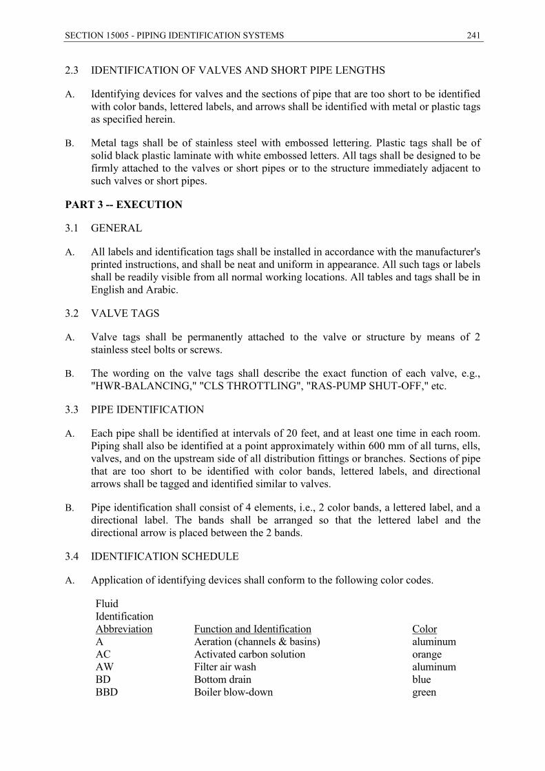
SECTION 15005 - PIPING IDENTIFICATION SYSTEMS 241
2.3 IDENTIFICATION OF VALVES AND SHORT PIPE LENGTHS
A. Identifying devices for valves and the sections of pipe that are too short to be identified with color bands, lettered labels, and arrows shall be identified with metal or plastic tags as specified herein.
B. Metal tags shall be of stainless steel with embossed lettering. Plastic tags shall be of solid black plastic laminate with white embossed letters. All tags shall be designed to be firmly attached to the valves or short pipes or to the structure immediately adjacent to such valves or short pipes.
PART 3 -- EXECUTION
3.1 GENERAL
A. All labels and identification tags shall be installed in accordance with the manufacturer's printed instructions, and shall be neat and uniform in appearance. All such tags or labels shall be readily visible from all normal working locations. All tables and tags shall be in English and Arabic.
3.2 VALVE TAGS
A. Valve tags shall be permanently attached to the valve or structure by means of 2 stainless steel bolts or screws.
B. The wording on the valve tags shall describe the exact function of each valve, e.g., "HWR-BALANCING," "CLS THROTTLING", "RAS-PUMP SHUT-OFF," etc.
3.3 PIPE IDENTIFICATION
A. Each pipe shall be identified at intervals of 20 feet, and at least one time in each room. Piping shall also be identified at a point approximately within 600 mm of all turns, ells, valves, and on the upstream side of all distribution fittings or branches. Sections of pipe that are too short to be identified with color bands, lettered labels, and directional arrows shall be tagged and identified similar to valves.
B. Pipe identification shall consist of 4 elements, i.e., 2 color bands, a lettered label, and a directional label. The bands shall be arranged so that the lettered label and the directional arrow is placed between the 2 bands.
3.4 IDENTIFICATION SCHEDULE
A. Application of identifying devices shall conform to the following color codes.
Fluid Identification Abbreviation Function and Identification Color A Aeration (channels & basins) aluminum AC Activated carbon solution orange AW Filter air wash aluminum BD Bottom drain blue BBD Boiler blow-down green
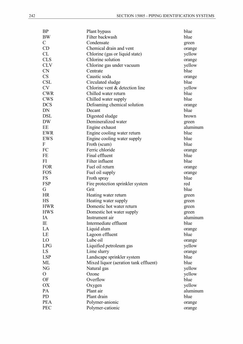
242 SECTION 15005 - PIPING IDENTIFICATION SYSTEMS
BP Plant bypass blue BW Filter backwash blue C Condensate green CD Chemical drain and vent orange CL Chlorine (gas or liquid state) yellow CLS Chlorine solution orange CLV Chlorine gas under vacuum yellow CN Centrate blue CS Caustic soda orange CSL Circulated sludge blue CV Chlorine vent & detection line yellow CWR Chilled water return blue CWS Chilled water supply blue DCS Defoaming chemical solution orange DN Decant blue DSL Digested sludge brown DW Demineralized water green EE Engine exhaust aluminum EWR Engine cooling water return blue EWS Engine cooling water supply blue F Froth (scum) blue FC Ferric chloride orange FE Final effluent blue FI Filter influent blue FOR Fuel oil return orange FOS Fuel oil supply orange FS Froth spray blue FSP Fire protection sprinkler system red G Grit blue HR Heating water return green HS Heating water supply green HWR Domestic hot water return green HWS Domestic hot water supply green IA Instrument air aluminum IE Intermediate effluent blue LA Liquid alum orange LE Lagoon effluent blue LO Lube oil orange LPG Liquified petroleum gas yellow LS Lime slurry orange LSP Landscape sprinkler system blue ML Mixed liquor (aeration tank effluent) blue NG Natural gas yellow O Ozone yellow OF Overflow blue OX Oxygen yellow PA Plant air aluminum PD Plant drain blue PEA Polymer-anionic orange PEC Polymer-cationic orange

SECTION 15005 - PIPING IDENTIFICATION SYSTEMS 243
PEN Polymer-nonionic orange PEF Primary effluent blue PI Plant influent blue PO Plant overflow blue PW Potable water green RAS Return activated sludge blue REW Reclaimed water blue RSL Raw sludge (primary sludge) brown RW Raw water blue RWL Rain water leader blue S Scum brown SA Sample lines blue SC Spare chemical orange SD Sanitary drains and vents blue SDR Storm drain blue SE Secondary effluent blue SF Sludge filtrate blue SG Sludge gas yellow SI Sodium silicate orange SL Sludge blue SN Supernatant blue SO sulfur dioxide (gas or liquid state) yellow SOW Softened water green SOS Sulfur dioxide solution orange SOV Sulfur dioxide gas under vacuum yellow SPD Sump pump discharge blue SS Sanitary sewer blue ST Steam aluminum SUC Structure underdrain collector blue SV Sulfur dioxide vent yellow SW Filter surface wash blue TFE Trickling filter effluent blue TPI Tertiary plant influent blue TPR Thickener pressurized recycle (DAF) blue TS Thickener subnatant (DAF) blue TSL Thickened sludge (DAF) brown TSO Thickener subnatant overflow (DAF) blue UW Utility water (non-potable water) blue V Vacuum aluminum WAS Waste activated sludge brown WLO Waste lube oil orange WW Filter waste washwater blue
- END OF SECTION –
244 SECTION 15006 - PIPE SUPPORTS
SECTION 15006 - PIPE SUPPORTS
PART 1 -- GENERAL
1.1 THE REQUIREMENT
A. The CONTRACTOR shall provide pipe supports, hangers, guides, and anchors, complete, in accordance with the Contract Documents.
1.2 CONTRACTOR SUBMITTALS
A. General: Submittals shall be in accordance with Section 01300 - Contractor Submittals.
B. Shop Drawings: Shop Drawings shall include the following information:
1. Drawings of pipe supports, hangers, anchors, and guides
2. Calculations for special supports and anchors.
PART 2 -- PRODUCTS
2.1 GENERAL REQUIREMENTS
A. Code Compliance: All piping systems and pipe connections to equipment shall be properly anchored and supported to prevent undue deflection, vibration, dislocation due to seismic events and line pressures, and stresses on piping, equipment, and structures. All supports and parts thereof shall conform to the requirements of DIN for Power Piping, except as supplemented or modified below. Supports for plumbing piping shall be in accordance with the latest edition of the applicable plumbing code or local administration requirements.
B. Structural Members: Wherever possible, pipes shall be supported from structural members. Where it is necessary to frame structural members between existing members, such supplementary members shall be provided by the CONTRACTOR. All supplementary members shall be in accordance with the requirements of the building code and the American Institute of Steel Construction and shall be acceptable to the Engineer.
C. Pipe Hangers: Pipe hangers shall be capable of supporting the pipe in all conditions of operation, allowing free expansion and contraction of the piping, and preventing excessive stress on equipment. All hangers shall have a means of vertical adjustment after erection. Hangers shall be designed to prevent becoming disengaged by any movement of the supported pipe. Hangers subject to shock, seismic disturbances, or thrust imposed by the actuation of safety valves, shall include hydraulic shock suppressors. All hanger rods shall be subject to tensile loading only.
D. Hangers Subject to Horizontal Movements: At hanger locations where lateral or axial movement is anticipated, suitable linkage shall be provided to permit such movement. Where horizontal pipe movement is greater than 1/2-inch(12mm), or where the hanger rod deflection from the vertical is greater than 4 degrees from the cold to the hot position of the pipe, the hanger rod and structural attachment shall be offset in such a manner that the rod is vertical in the hot position.

SECTION 15006 - PIPE SUPPORTS 245
E. Spring-Type Hangers: Spring-type pipe hangers shall be provided for piping subject to vibration or vertical expansion and contraction, such as engine exhausts and similar piping. All spring-type hangers shall be sized to the manufacturer's printed recommendations and the loading conditions encountered. Variable spring supports shall be provided with means to limit misalignment, buckling, eccentric loading, or to prevent overstressing of the spring, and with means to indicate at all times the compression of the spring. Supports shall be capable of accommodating at least 4 times the maximum travel due to thermal expansion.
F. Thermal Expansion: Wherever expansion and contraction of piping is expected, a sufficient number of expansion loops or joints shall be provided, together with the necessary rolling or sliding supports, anchors, guides, pivots, and restraints permitting the piping to expand and contract freely in directions away from the anchored points. All components shall be structurally suitable to withstand all loads imposed.
G. Heat Transmission: Supports, hangers, anchors, and guides shall be so designed and insulated, that excessive heat will not be transmitted to the structure or to other equipment.
H. Riser Supports: Where practical, risers shall be supported on each floor with riser clamps and lugs, independent of the connected horizontal piping.
I. Freestanding Piping: Free-standing pipe connections to equipment such as pumps shall be firmly attached to steel frames fabricated from angles, channels, or I-beams anchored to the structure. Exterior, free-standing overhead piping shall be supported on fabricated pipe stands consisting of pipe columns anchored to concrete footings, with horizontal, welded steel angles and U-bolts or clamps securing the pipes.
J. Materials of Construction:
1. General: All pipe support assemblies inside pump station sites shall include framing, hardware, and anchors, and shall be constructed of Type 1.4301 stainless steel, unless otherwise indicated.
2. Submerged Supports: All submerged piping, as well as piping, conduits, and equipment in hydraulic structures within 24 inches(610mm) of the water level, shall be supported with support, assemblies, including framing, hardware, and anchors, constructed of Type 1.4401 or 1.4571 stainless steel, unless otherwise indicated.
3. Corrosive: All piping in chemical and corrosive areas shall be supported with support assemblies, including framing, hardware, and anchors, constructed of Type 1.4401 or 1.4571 stainless steel, unless otherwise indicated.
K. Point Loads: Any meters, valves, heavy equipment, and other point loads on pipes, shall be supported, according to manufacturer's recommendations to avoid undue pipe stresses and failures.
2.2 SUPPORT SPACING
A. Supports for piping with the longitudinal axis in approximately a horizontal position shall be spaced to prevent excessive sag, bending, and shear stresses in the piping, with special consideration given where components such as flanges and valves impose
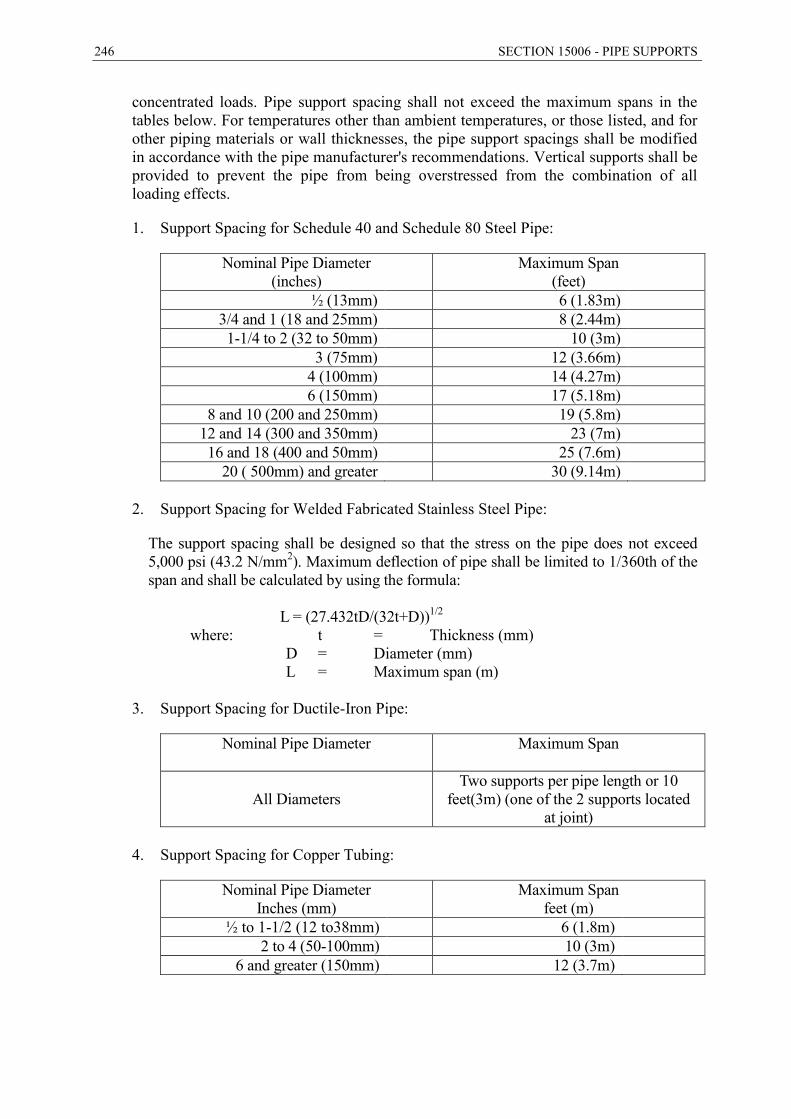
246 SECTION 15006 - PIPE SUPPORTS
concentrated loads. Pipe support spacing shall not exceed the maximum spans in the tables below. For temperatures other than ambient temperatures, or those listed, and for other piping materials or wall thicknesses, the pipe support spacings shall be modified in accordance with the pipe manufacturer's recommendations. Vertical supports shall be provided to prevent the pipe from being overstressed from the combination of all loading effects.
1. Support Spacing for Schedule 40 and Schedule 80 Steel Pipe:
Nominal Pipe Diameter (inches)
Maximum Span (feet)
½ (13mm) 6 (1.83m) 3/4 and 1 (18 and 25mm) 8 (2.44m) 1-1/4 to 2 (32 to 50mm) 10 (3m)
3 (75mm) 12 (3.66m) 4 (100mm) 14 (4.27m) 6 (150mm) 17 (5.18m)
8 and 10 (200 and 250mm) 19 (5.8m) 12 and 14 (300 and 350mm) 23 (7m) 16 and 18 (400 and 50mm) 25 (7.6m)
20 ( 500mm) and greater 30 (9.14m)
2. Support Spacing for Welded Fabricated Stainless Steel Pipe:
The support spacing shall be designed so that the stress on the pipe does not exceed 5,000 psi (43.2 N/mm2). Maximum deflection of pipe shall be limited to 1/360th of the span and shall be calculated by using the formula:
L = (27.432tD/(32t+D))1/2
where: t = Thickness (mm) D = Diameter (mm) L = Maximum span (m)
3. Support Spacing for Ductile-Iron Pipe:
Nominal Pipe Diameter
Maximum Span
All Diameters Two supports per pipe length or 10
feet(3m) (one of the 2 supports located at joint)
4. Support Spacing for Copper Tubing:
Nominal Pipe Diameter Inches (mm)
Maximum Span feet (m)
½ to 1-1/2 (12 to38mm) 6 (1.8m) 2 to 4 (50-100mm) 10 (3m)
6 and greater (150mm) 12 (3.7m)
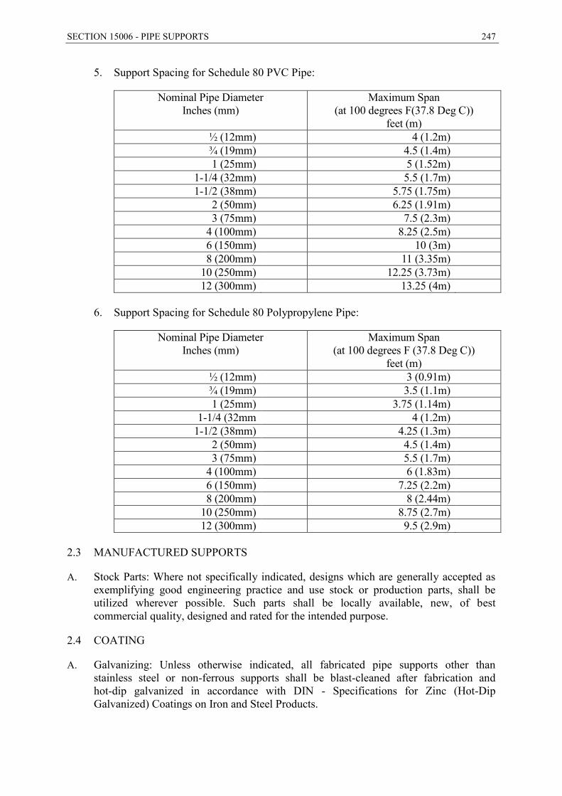
SECTION 15006 - PIPE SUPPORTS 247
5. Support Spacing for Schedule 80 PVC Pipe:
Nominal Pipe Diameter Inches (mm)
Maximum Span (at 100 degrees F(37.8 Deg C))
feet (m) ½ (12mm) 4 (1.2m) ¾ (19mm) 4.5 (1.4m) 1 (25mm) 5 (1.52m)
1-1/4 (32mm) 5.5 (1.7m) 1-1/2 (38mm) 5.75 (1.75m)
2 (50mm) 6.25 (1.91m) 3 (75mm) 7.5 (2.3m)
4 (100mm) 8.25 (2.5m) 6 (150mm) 10 (3m) 8 (200mm) 11 (3.35m)
10 (250mm) 12.25 (3.73m) 12 (300mm) 13.25 (4m)
6. Support Spacing for Schedule 80 Polypropylene Pipe:
Nominal Pipe Diameter Inches (mm)
Maximum Span (at 100 degrees F (37.8 Deg C))
feet (m) ½ (12mm) 3 (0.91m) ¾ (19mm) 3.5 (1.1m) 1 (25mm) 3.75 (1.14m)
1-1/4 (32mm 4 (1.2m) 1-1/2 (38mm) 4.25 (1.3m)
2 (50mm) 4.5 (1.4m) 3 (75mm) 5.5 (1.7m)
4 (100mm) 6 (1.83m) 6 (150mm) 7.25 (2.2m) 8 (200mm) 8 (2.44m)
10 (250mm) 8.75 (2.7m) 12 (300mm) 9.5 (2.9m)
2.3 MANUFACTURED SUPPORTS
A. Stock Parts: Where not specifically indicated, designs which are generally accepted as exemplifying good engineering practice and use stock or production parts, shall be utilized wherever possible. Such parts shall be locally available, new, of best commercial quality, designed and rated for the intended purpose.
2.4 COATING
A. Galvanizing: Unless otherwise indicated, all fabricated pipe supports other than stainless steel or non-ferrous supports shall be blast-cleaned after fabrication and hot-dip galvanized in accordance with DIN - Specifications for Zinc (Hot-Dip Galvanized) Coatings on Iron and Steel Products.
248 SECTION 15006 - PIPE SUPPORTS
B. Other Coatings: Other than stainless steel or non-ferrous supports, all supports shall receive protective coatings in accordance with the requirements of Section 09800 - Protective Coating.
PART 3 -- EXECUTION
3.1 INSTALLATION
A. General: All pipe supports, hangers, brackets, anchors, guides, and inserts shall be fabricated and installed in accordance with the manufacturer's printed instructions and ablicable DIN standards. All concrete inserts for pipe hangers and supports shall be coordinated with the formwork.
B. Appearance: Pipe supports and hangers shall be positioned to produce an orderly, neat piping system. All hanger rods shall be vertical, without offsets. Hangers shall be adjusted to line up groups of pipes at the proper grade for drainage and venting, as close to ceilings or roofs as possible, without interference with other work.
3.2 FABRICATION
A. Quality Control: Pipe hangers and supports shall be fabricated and installed by experienced welders and fitters, using the best welding procedures available. Fabricated supports shall be neat in appearance without sharp corners, burrs, and edges.
- END OF SECTION –
SECTION 15075 - METERS, GENERAL 249
SECTION 15075 - METERS, GENERAL
PART 1 -- GENERAL
1.1 THE REQUIREMENT
A. The Contractor shall provide meters and flow measurement devices, complete and operable, in accordance with the Contract Documents.
B. Unless indicated otherwise, the requirements of this Section apply to all meters in Division 15 of the Specifications.
1.2 REFERENCE SPECIFICATIONS, CODES, AND STANDARDS
A. Commercial Standards
DIN 1301 Units – Names, Symbols DIN 2501-1 Flanges; Connecting Dimensions DIN EN 14154 Water meters VDE 410 Specification for Electrical Measuring Instruments IEC 70 Degrees of Protection Provided by Enclosure (IP)
1.3 CONTRACTOR SUBMITTALS
A. General: All flowmeters shall conform to DIN 19648, PN16. Furnish submittals in
accordance with Section 01300 - Contractor Submittals.
B. Shop Drawings: Each meter shall be identified with its equipment number, as indicated.
C. Manufacturer's Data: With the Shop Drawings, furnish certified curves indicating flow versus differential pressure and any other information called for in the individual meter specifications.
D. EMPLOYER'S Manual: Furnish 5 identical copies of complete operation and maintenance instructions of all the metering systems including instrumentation and controls, in accordance with the paragraph “Operational Procedures” in Section 01300.
E. Spare Parts List: The Contractor shall furnish a list of manufacturer's recommended spare parts.
F. Special Tools: A list of special tools shall be submitted to the Engineer.
G. Documentation: After completion the Contractor shall furnish to the Employer the manufacturer's written guarantees, that the metering systems will operate within the published accuracies and flow ranges and meet these Specifications. The Contractor shall also furnish the manufacturer's warranties as published in its literature and as specified.
250 SECTION 15075 - METERS, GENERAL
1.4 QUALITY ASSURANCE
A. Accuracy Requirements: Unless otherwise indicated, flow meters shall be guaranteed to register flow to an accuracy of +2 percent of actual flow throughout the range indicated. Density measuring equipment shall have a degree of accuracy within +2 percent of actual solids content over the range indicated.
PART 2 -- PRODUCTS
2.1 SPARE PARTS AND SPECIAL TOOLS
A. Furnish the spare parts listed in the individual meter sections. Spare parts shall be suitably packaged and labeled by part name and associated equipment number.
B. The Contractor shall furnish special tools suitably wrapped and identified for application. Special tools shall include substitute steel spools for each meter for maintenance purposes. Each spool shall be labeled to identify the associated meter including the meter identification number, size, and service.
PART 3 -- EXECUTION
3.1 SERVICES OF MANUFACTURER
A. After installation, the Contractor shall obtain the services of an experienced factory service representative to inspect the installation and test all meters for proper performance.
B. Instruction of EMPLOYER's Personnel: After completion of the installation and during startup of the plant, the Contractor shall instruct the Employer's personnel in the proper operation, maintenance and repair of all metering equipment. For this purpose, the Contractor shall obtain the services of an experienced factory service representative, who shall spend sufficient time on the Site to fully instruct the Employer's operating personnel on all phases of the metering equipment.
3.2 INSTALLATION
A. The Contractor shall assemble and install equipment in strict accordance with the manufacturer's published instructions, under the supervision of the manufacturer's representative. Installation shall be accomplished by competent craftsmen in a workmanlike manner.
B. Meters shall be installed in easily accessible locations for ease of reading and maintenance, and, where shown, for balancing of flow in several lines, in conjunction with throttling and shut-off valves. Wherever possible, all meters shall be installed in such a way to provide the manufacturer's recommended straight approach and straight piping downstream. Meters and shut-off and balancing valves shall be firmly supported from the structure or from the floor with approved supports. In-line meters shall be installed to provide full-line flow and not less than the manufacturer's recommended head at all times.

SECTION 15075 - METERS, GENERAL 251
3.3 TESTING
A. Equipment shall be prepared for operational use in accordance with manufacturer's instructions, including bench test and calibration, where required.
B. Each item shall be subjected to an operating test over the total range of capability of the equipment. Where applicable, tests shall be conducted in accordance with the Test Code of the Standards of the Hydraulic Institute. The Contractor shall obtain copies of factory test certifications and shall notify the Engineer one week in advance of all tests to be conducted on Site.
- END OF SECTION -
252 SECTION 15081 - ELECTROMAGNETIC FLOW METERS
SECTION 15081 - ELECTROMAGNETIC FLOW METERS
PART 1 -- GENERAL
1.1 THE REQUIREMENT
A. The CONTRACTOR shall provide electromagnetic flow measuring systems, complete and operable, in accordance with the Contract Documents.
B. The electromagnetic flow measuring systems shall be able to perform in accordance with the control strategies as described in
1.2 CONTRACTOR SUBMITTALS
A. General: Submittals shall be furnished in accordance with Section 01300 - Contractor Submittals.
B. Shop Drawings: Shop drawings for electromagnetic flow meters shall be included in the Analog Hardware Submittal required by Section 17100- Process Control and Instrumentation Systems.
PART 2 -- PRODUCTS
2.1 ELECTROMAGNETIC FLOW METERS
A. General
1. Electromagnetic flowmeter systems shall be of the low frequency electromagnetic induction type and produce a DC pulsed signal directly proportional to and linear with the liquid flow rate. Complete zero stability shall be an inherent characteristic of the flowmeter system. Each electromagnetic flow metering system shall include a metering tube, signal cable, transmitter and flowmeter grounding rings.
2. Electromagnetic flow meters and electronics shall be manufactured at facilities certified to the quality standards of ISO Standard 9001 - Quality Systems - Model for Quality Assurance in Design/Development, Production, Installation, and Servicing.
B. Metering Tube: The metering tube shall have the following:
1. Constructed of 1.4301 or 1.4401 stainless steel with flanged connections
2. Utilize a minimum of 2 bullet-nosed, self-cleaning electrodes
3. Liner in conformance with the Manufacturer's recommendation for the meter's intended service
4. Electrodes constructed of materials which are in conformance with the Manufacturer's recommendation for the meter's intended service
5. Meter housing rated for IP 65 submergence conditions

SECTION 15081 - ELECTROMAGNETIC FLOW METERS 253
6. Meter coating consisting of epoxy painted finish
7. Two grounding rings which are in conformance with the Manufacturer's bore and material recommendation for the meter's intended service. Grounding rings shall be designed to protect and shield from process abrasion the liner's edge interface at the meter's end.
C. Transmitter: The microprocessor-based signal converter/transmitter shall have the following:
1. Utilize DC pulse technique to drive flux-producing coils
2. Convert DC pulse signal from the tube to a standard 4-20 mA signal into a minimum of 700 ohms.
3. A 6-digit LCD display for flowrate, percent of span, and totalizer
4. An operator interface consisting of keypads which respond to English text entry
5. Integral zero return to provide a consistent zero output signal in response to an external dry contact closure
6. Integral low flow cut-off and zero return
7. Automatic range change
8. Capable of measuring flow in both directions
9. Programmable parameters including meter size, full scale Q, electromagnetic field frequency, primarily constant, time constant
10. Data retention for a minimum of 5 years without auxiliary main or battery power
11. Self diagnostics and automatic data checking
12. Protected terminals and fuses in a separate compartment which isolates field connection from electronics
13. Utilizes "Smart" technology which employs a hand-held configuration terminal and outputs a digital flow signal superimposed on 4-20 mA signal and complies to HART protocol.
14. Produces a scalable frequency output, 0 to 100 Hz, transistor switch closure up to 5.75 W externally powered, 5 to 24 VDC.
15. Can tolerate ambient temperature operating limits of -20 to 140 degrees F (-29 to 60 degrees C).
D. Performance Requirements
1. Time Constant: 0.5 to 1000 seconds
2. Accuracy: ±0.5% of the real velocity within a range of 0 to 10 m/s.
254 SECTION 15081 - ELECTROMAGNETIC FLOW METERS
3. Repeatability: 0.5 percent of full scale
4. Isolation: either galvanic or optic
5. Power consumption: 30 watts max
6. Power supply: 220 VAC, plus or minus 10 percent
E. Factory Testing:
1. Each flow metering system shall be hydraulically calibrated at a facility which is traceable to the National Institute of Testing Standards. A real-time computer generated printout of the actual calibration data indicating apparent and actual flows at 20%, 40%, 60%, 80% and 100% of the calibrated range shall be submitted to the ENGINEER at least thirty (30) days prior to shipment of the meters to the project site.
PART 3 -- EXECUTION
3.1 INSTALLATION
A. General: Electromagnetic flow measuring systems shall be handled, installed, calibrated, tested, precommissioned, and Manufacturer's service and training shall be furnished.
- END OF SECTION -
SECTION 15183 - GAUGES 255
SECTION 15183 - GAUGES
PART 1 -- GENERAL
1.1 THE REQUIREMENT
A. The CONTRACTOR shall provide pressure and vacuum gauges as specified, complete, including all fittings, snubbers, connections, gaskets, supports, and accessories in the locations shown or specified, in accordance with the Contract Documents.
PART 2 -- PRODUCTS
2.1 PRESSURE AND VACUUM GAUGES
A. General: Pressure gauges shall be provided on suction and discharge connections to pumps, as specified under pumps; on discharge connections from blowers and compressors; each side of pressure reducing valves; and where shown. Vacuum gauges shall be provided for vacuum pumps and where shown. In all locations (such as certain pump suction connections) where pressures may vary from below to above atmospheric head, compound gauges shall be installed.
B. Gauge Construction: Gauges shall be industrial quality type with Type 316 stainless steel movement and stainless steel or alloy case. Unless otherwise shown or specified, gauges shall have a 3-1/2-inch dial, 1/4-inch threaded connection, a Type 316 stainless steal snubber adapter, and a shut-off valve. Gauges shall be calibrated to read in applicable units, with an accuracy of plus and minus 1 percent, to 150 percent of the working pressure or vacuum of the pipe or vessel to which they are connected. All gauges shall be vibration and shock resistant.
C. Diaphragm Seal: Gauges attached to systems involving chemical solutions, corrosive fluids, sludge, sewage, or other liquids containing solids, shall be equipped with diaphragm seals, or equal protective pressure or vacuum sensing devices, as follows:
1. For: sewage, sludge,
liquids containing solids, pulsating flow
Seals of all Type 316 stainless steel, with stainless steel diaphragm for pressures over 15 psi, and elastomer diaphragm for pressures of 15 psi and below, Type 316 stainless steel nuts and bolts, fill connection and valved flush port size 1/4-inch NPT, capable of disassembly without loss of filler fluid.
256 SECTION 15183 - GAUGES
2. For: chlorine and sulfur dioxide under pressure
Seals of carbon steel with silver diaphragm of 800 psi rating.
3. For: chemical solutions,
sewage, sludge, etc., where breakage does not create a major shutdown
Seals with PVC body for removable mounting rated at 200 psi, with Type 316 stainless steel bolts and nuts, 1/2-inch inlet, 1/4-inch outlet, liquid-filled with Teflon diaphragm for pressure, and suitable elastomer diaphragm for vacuum service.
2.2 SLEEVE PRESSURE GAUGES
A. General: Sleeved pressure gauges shall be provided where shown.
B. Construction: Pressure shall be sensed by a flexible sleeve contained in a flanged cast iron or steel spool or wafer body, and transmitted to the gauge through a captive fluid. The sleeve shall be of Buna N and fabricated so as to isolate the body from the process liquid. Gauges shall be calibrated to read in meters of water column for pressures of 20 meters or less and in bars for pressures of 2 bars or more, with an accuracy of ±1 percent, to 150 percent of the working pressure of the system to which they are connected.
PART 3 -- EXECUTION
3.1 INSTALLATION
A. All gauges shall be installed with the face in the vertical position, at the locations shown in the Contract Documents, and in strict accordance with the manufacturer's printed instructions. Care shall be taken to minimize the effect of water hammer or vibrations on the gauges. In extreme cases, the gauges may have to be mounted independently, with flexible connectors.
- END OF SECTION –
SECTION 15200 - VALVES, GENERAL 257
SECTION 15200 - VALVES, GENERAL
PART 1 -- GENERAL
1.1 THE REQUIREMENT
A. The CONTRACTOR shall provide all valves, actuators, and appurtenances, complete and operable, in accordance with the Contract Documents.
B. The requirements of Section 11000 - Equipment General Provisions, apply to the WORK of this Section.
C. The provisions of this Section shall apply to all valves and valve actuators except where otherwise indicated. Valves and actuators in particular locations may require a combination of units, sensors, limit switches, and controls indicated in other Sections of the Specifications.
D. Where a valve is to be supported by means other than the piping to which it is attached, the CONTRACTOR shall obtain from the valve manufacturer a design for support and foundation that satisfies the criteria in Section 11000. The design, including drawings and calculations sealed by an engineer, shall be submitted with the Shop Drawings. When the design is approved, the support shall be provided.
E. Unit Responsibility: A single manufacturer shall be made responsible for coordination of design, assembly, testing, and furnishing of each valve; however, the CONTRACTOR shall be responsible to the Engineer for compliance with the requirements of each valve section. Unless indicated otherwise, the responsible manufacturer shall be the manufacturer of the valve.
F. Single Manufacturer: Where two or more valves of the same type and size are required, the valves shall be furnished by the same manufacturer.
1.2 CONTRACTOR SUBMITTALS
A. General: Submittals shall be furnished in accordance with Section 01300 - Contractor Submittals.
B. Shop Drawings: Shop Drawings shall contain the following information:
1. Valve name, size, Cv factor, pressure rating, identification number (if any), and specification section number.
2. Complete information on valve actuator, including size, Manufacturer, model number, limit switches, and mounting.
3. Cavitation limits for all control valves.
4. Assembly drawings showing part nomenclature, materials, dimensions, weights, and relationships of valve handles, handwheels, position indicators, limit switches, integral control systems, needle valves, and control systems.
258 SECTION 15200 - VALVES, GENERAL
5. Data in accordance with Section 16460 - Electric Motors for all electric motor-actuated valves.
6. Complete wiring diagrams and control system schematics.
7. Valve Labeling: A schedule of valves to be furnished with stainless steel tags, indicating in each case the valve location and the proposed wording for the label.
C. Technical Manual: The Technical Manual shall contain the required information for each valve.
D. Spare Parts List: A Spare Parts List shall contain the required information for each valve assembly, where indicated.
E. Factory Test Data: Where indicated, signed, dated, and certified factory test data for each valve requiring certification shall be submitted before shipment of the valve. The data shall also include certification of quality and test results for factory-applied coatings.
PART 2 -- PRODUCTS
2.1 PRODUCTS
A. General: Valves and gates shall be new and of current manufacture. Shut-off valves 6-inches and larger shall have actuators with position indicators. Buried valves shall be provided with valve boxes and covers containing position indicators and valve extensions. Manual shut-off valves mounted higher than 7-feet above working level shall be provided with chain actuators.
B. Valve Actuators: Unless otherwise indicated, valve actuators shall be in accordance with Section 15201 - Valve and Gate Actuators.
C. Dismantling Joints: dismantling joints shall be considered at each valve, meter or any fitting within a chamber and as per the drawings and typical details, the dismantling joint shall have a diameter, pressure rating, material and protective coating compatible with the attached fitting and pipeline.
D. Protective Coating: The exterior surfaces of all valves and the wet interior surfaces of ferrous valves of sizes 4 inches (100 mm) and larger shall be coated in accordance with Section 09800 - Protective Coating. The valve Manufacturer shall certify in writing that the required coating has been applied and tested in the manufacturing plant prior to shipment, in accordance with these Specifications. Flange faces of valves shall not be epoxy coated.
E. Valve Labeling: Except when such requirement is waived by the ENGINEER in writing, a label shall be provided on all shut-off valves and control valves except for hose bibs and chlorine cylinder valves. The label shall be of 1/16-inch (1.0 mm) plastic or stainless steel, minimum 2 inches by 4 inches (50 mm and 100 mm) in size, as indicated in Section 15005 - Piping Identification Systems, and shall by permanently attached to the valve or on the wall adjacent to the valve as directed by the ENGINEER.

SECTION 15200 - VALVES, GENERAL 259
F. Valve Testing: As a minimum, unless otherwise indicated or recommended by the reference Standards, valves 3 inches (75 mm) in diameter and smaller shall be tested in accordance with manufacturer's standard and 4 inches (100 mm)in diameter and larger shall be factory tested as follows:
1. Hydrostatic Testing: Valve bodies shall be subjected to internal hydrostatic pressure equivalent to twice the water rated pressure of the valve. Metallic valves rating pressures shall be at 100 degrees F and plastic valves shall be 73 degrees, or at higher temperature according to type of material. During the hydrostatic test, there shall be no leakage through the valve body, end joints, or shaft seals, nor shall any part of the valve be permanently deformed. The duration shall be sufficient time to allow visual examination for leakage. Test duration shall be at least 10 minutes.
2. Seat Testing: Valves shall be tested for leaks in the closed position with the pressure differential across the seat equal to the water rated pressure of the valve. The duration of test shall be sufficient time to allow visual examination for leakage. Test duration shall be at least 10 minutes. Leakage past the closed valve shall not exceed 1 fluid ounce per hour per inch diameter for metal seated valves and drop-tight for resilient seated valves.
3. Performance Testing: All valves shall be shop operated from fully closed to fully open position and reverse under no-flow conditions in order to demonstrate the valve assembly operates properly.
G. Certification: Prior to shipment, the CONTRACTOR shall submit for valves over 12 inches in size, certified, notarized copies of the hydrostatic factory tests, showing compliance with the applicable standards of AWWA, ANSI, or ASTM.
H. Valve Marking: Valve bodies shall be permanently marked in accordance with MSS SP25 - Standard Marking Systems for Valves, Fittings, Flanges, and Unions.
2.2 MATERIALS
A. General: Materials shall be suitable for the intended application. Materials not indicated shall be high-grade standard commercial quality, free from defects and imperfections that might affect the serviceability of the product for the purpose for which it is intended. Unless otherwise indicated, valve and actuator bodies shall conform to the following requirements:
1. Cast Iron: Close-grained gray cast iron, conforming to ASTM A 48 - Gray Iron Castings, Class 30, or to ASTM A 126 - Gray Iron Castings for Valves, Flanges, and Pipe Fittings.
2. Ductile Iron: ASTM A 536 - Ductile Iron Castings, or to ASTM A 395 - Ferritic Ductile Iron Pressure-Retaining Castings for Use at Elevated Temperatures.
3. Steel: ASTM A 216 - Steel Castings, Carbon Suitable for Fusion Welding for High-Temperature Service, or to ASTM A 515 - Pressure Vessel Plates, Carbon Steel, for Intermediate- and Higher-Temperature Service.

260 SECTION 15200 - VALVES, GENERAL
4. Bronze: ASTM B 62 - Composition Bronze or Ounce Metal Castings, and valve stems not subject to dezincification shall conform to ASTM B 584 - Copper Alloy Sand Castings for General Applications.
5. Stainless Steel: Stainless steel valve and operator bodies and trim shall conform to ASTM A 351 - Steel Castings, Austenitic, for High-Temperature Service, Grade CF8M, or shall be Type 316 stainless steel.
6. PVC: Poly Vinyl Chloride materials for valve body, flanges, and cover shall conform to Cell Classification 12454.
7. CPVC: Chlorinated Poly Vinyl Chloride materials for valve body, flanges, and cover shall conform to Cell Classification 23447.
8. NSF Standard 14: All materials shall be listed for use in contact with potable water.
2.3 VALVE CONSTRUCTION
A. Bodies: Valve bodies shall be cast, molded (in the case of plastic valves), forged, or welded of the materials indicated, with smooth interior passages. Wall thicknesses shall be uniform in agreement with the applicable standards for each type of valve, without casting defects, pinholes, or other defects that could weaken the body. Welds on welded bodies shall be done by certified welders and shall be ground smooth. Valve ends shall be as indicated, and be rated for the maximum temperature and pressure to which the valve will be subjected.
B. Bonnets: Valve bonnets shall be clamped, screwed, or flanged to the body and shall be of the same material, temperature, and pressure rating as the body. The bonnets shall have provision for the stem seal with the necessary glands, packing nuts, or yokes.
C. Stems: Valve stems shall be of the materials indicated, or, if not indicated, of the best commercial material for the specific service, with adjustable stem packing, O-rings, Chevron V-type packing, or other suitable seal. Where subject to dezincification, bronze valve stems shall conform to ASTM B 62, containing not more than 5 percent of zinc or more than 2 percent of aluminum, with a minimum tensile strength of 30,000 psi, a minimum yield strength of 14,000 psi, and an elongation of at least 10 percent in 2 inches. Where dezincification is not a problem, bronze conforming to ASTM B 584 may be used, except that zinc content shall not exceed 16 percent.
D. Stem Guides: Stem guides shall be provided, spaced 10-feet on centers unless the manufacturer can demonstrate by calculation that a different spacing is acceptable. Submerged stem guides shall be 304 stainless steel.
E. Internal Parts: Internal parts and valve trim shall be as indicated for each individual valve. Where not indicated, valve trim shall be of Type 316 stainless steel or other best suited material.
F. Nuts and Bolts: Nuts and bolts on valve flanges and supports shall be in accordance with Section 05500 - Miscellaneous Metalwork.
SECTION 15200 - VALVES, GENERAL 261
2.4 VALVE ACCESSORIES
A. Valves shall be furnished complete with the accessories required to provide a functional system.
2.5 SPARE PARTS
A. The CONTRACTOR shall furnish the required spare parts suitably packaged and labeled with the valve name, location, and identification number. The CONTRACTOR shall also furnish the name, address, and telephone number of the nearest distributor for the spare parts of each valve. Spare parts are intended for use by the OWNER, after expiration of the correction of defects period.
2.6 MANUFACTURERS
A. Manufacturer's Qualifications: Valve manufacturers shall have a successful record of not less than 5 years in the manufacture of the valves indicated.
PART 3 -- EXECUTION
3.1 VALVE INSTALLATION
A. General: Valves, actuating units, stem extensions, valve boxes, and accessories shall be installed in accordance with the Manufacturer's written instructions and as indicated. Gates shall be adequately braced to prevent warpage and bending under the intended use. Valves shall be firmly supported to avoid undue stresses on the pipe.
B. Access: Valves shall be installed with easy access for actuation, removal, and maintenance and to avoid interference between valve actuators and structural members, handrails, or other equipment.
C. Valve Accessories: Where combinations of valves, sensors, switches, and controls are indicated, the CONTRACTOR shall properly assemble and install such items so that systems are compatible and operating properly. The relationship between interrelated items shall be clearly noted on Shop Drawing submittals.
- END OF SECTION –
262 SECTION 15201 - VALVE ACTUATORS
SECTION 15201 - VALVE ACTUATORS
PART 1 -- GENERAL
1.1 THE REQUIREMENT
A. The CONTRACTOR shall provide valve actuators and appurtenances, complete and operable, in accordance with the Contract Documents.
B. The provisions of this Section shall apply to all valves, except where otherwise indicated in the Contract Documents.
C. Unit Responsibility: The valve manufacturer shall be made responsible for coordination of design, assembly, testing, and installation of actuators on the valves; however, the CONTRACTOR shall be responsible to the Employer for compliance of the valves, and actuators with the Contract Documents.
D. Single Manufacturer: Where two or more valve and actuators of the same type or size are required, the actuators shall be produced by the same Manufacturer.
1.2 CONTRACTOR SUBMITTALS
A. General: Submittals shall be furnished in accordance with Section 01300 - Contractor Submittals and Section 15200 - Valves, General.
B. Shop Drawings: Shop Drawings of all actuators shall be submitted together with the valve submittals as a complete package.
PART 2 -- PRODUCTS
2.1 GENERAL
A. General: Unless otherwise indicated, shut-off and throttling valves and externally-actuated valves and gates shall be provided with manual or power actuators. The CONTRACTOR shall furnish actuators complete and operable with mounting hardware, motors, gears, controls, wiring, solenoids, handwheels, levers, chains, and extensions, as applicable. Actuators shall have the torque ratings equal to or greater than required for valve seating and dynamic torques, whichever is greater and shall be capable of holding the valve in any intermediate position between fully-open and fully-closed without creeping or fluttering. All wires of motor-driven actuators shall be identified by unique numbers.
B. Manufacturers: Where indicated, certain valves may be provided with actuators manufactured by the valve Manufacturer. Where actuators are furnished by different manufacturers, the CONTRACTOR shall coordinate selection to have the fewest number of manufacturers possible.
C. Materials: Actuators shall be current models of the best commercial quality materials and liberally-sized for the required torque. Materials shall be suitable for the environment in which the valve or gate is to be installed.

SECTION 15201 - VALVE ACTUATORS 263
D. Mounting: Actuators shall be securely mounted by means of brackets or hardware specially designed and sized for this purpose and of ample strength. The word "open" shall be cast on each valve or actuator with an arrow indicating the direction to open in the counter-clockwise direction. Gear and power actuators shall be equipped with position indicators. Where possible, manual actuators shall be located between 48 and 60 inches above the floor or the permanent working platform.
E. Standard: Unless otherwise indicated and where applicable, actuators shall be in accordance with ANSI/AWWA C 540 - AWWA Standard for Power-Actuating Devices for Valves and Sluice Gates.
F. Functionality: Electric, pneumatic, and hydraulic actuators shall be coordinated with the power requirements of Division 16 and instrumentation equipment indicated in Section 17100 - Process Control and Instrumentation Systems.
2.2 MANUAL ACTUATORS
A. General: Unless otherwise indicated, valves shall be furnished with manual actuators. Valves in sizes up to and including 100 mm shall have direct acting lever or handwheel actuators of the Manufacturer's best standard design. Larger valves and gates shall have gear-assisted manual actuators, with an operating pull of maximum 60 pounds (25 Kg) on the rim of the handwheel. Buried and submerged gear-assisted valves, gates, gear-assisted valves for pressures higher than 250 psi, valves 750 mm in diameter and larger, and where so indicated, shall have worm-gear actuators, hermetically-sealed and grease-packed, where buried or submerged. All other valves 150 mm to 600 mm in diameter may have traveling-nut actuators, worm-gear actuators, spur- or bevel-gear actuators, as appropriate for each valve.
B. Buried Valves: Unless otherwise indicated, buried valves shall have extension stems to grade, with square nuts or floor stands, position indicators, and cast-iron or steel pipe extensions with valve boxes, covers, and operating keys. Where so indicated, buried valves shall be in cast-iron, concrete, or similar valve boxes with covers of ample size to allow operation of the valve actuators. Covers of valve boxes shall be permanently labeled as requested by the local Utility Company or the ENGINEER. Wrench-nuts shall comply with AWWA C 500 -Metal - Seated Gate Valves for Water Supply Service.
C. Chain Actuator: Manually-activated valves with the stem located more than 7 feet (2100 mm) above the floor or operating level shall be provided with chain drives consisting of sprocket-rim chain wheels, chain guides, and operating chains provided by the valve Manufacturer. The wheel and guide shall be of ductile-iron, cast-iron, or steel, and the chain shall be hot-dip galvanized steel or stainless steel, extending to 5 feet 6 inches (1650 mm) above the operating floor level. The valve stem of chain-actuated valves shall be extra strong to allow for the extra weight and chain pull. Hooks shall be provided for chain storage where chains interfere with pedestrian traffic.
D. Floor Boxes: Hot-dip galvanized cast-iron or steel floor boxes and covers to fit the slab thickness shall be provided for operating nuts in or below concrete slabs. For operating nuts in the concrete slab, the cover shall be bronze-bushed.
264 SECTION 15201 - VALVE ACTUATORS
E. Tee Wrenches: Buried valves with floor boxes shall be furnished with 2 operating keys or 1 key per 10 valves whichever is greater. Tee wrenches, sized so that the tee handle will be 0.6 to 1.2 meter above ground, shall fit the operating nuts.
F. Manual Worm-Gear Actuator: The actuator shall consist of a single or double reduction gear unit contained in a weather-proof cast-iron or steel body with cover and minimum 300 mm diameter handwheel. The actuator shall be capable of 90-degree rotation and shall be equipped with travel stops capable of limiting the valve opening and closing. The actuator shall consist of spur or helical gears and worm-gearing. The spur or helical gears shall be of hardened alloy steel and the worm-gear shall be alloy bronze. The worm-gear shaft and the handwheel shaft shall be of 17-4 PH or similar stainless steel. All gearing shall be accurately cut with hobbing machines. Ball or roller bearings shall be used throughout. Actuator output gear changes shall be mechanically possible by simply changing the exposed or helical gearset ratio without further disassembly of the actuator. All gearing shall be designed for a 100 percent overload.
G. Traveling-Nut Actuator: The actuator shall consist of a traveling-nut with screw (Scotch yoke) contained in a weather-proof cast-iron or steel housing with spur gear and minimum 300 mm diameter handwheel. The screw shall run in 2 end bearings, and the actuator shall be self-locking to maintain the valve position under any flow condition. The screw and gear shall be of hardened alloy steel or stainless steel, and the nut and bushings shall be of alloy bronze. The bearings and gear shall be grease-lubricated by means of grease nipples. All gearing shall be designed for a 100 percent overload.
2.3 ELECTRIC MOTOR ACTUATORS
A. General
1. Equipment Requirements: Where electric motor actuators are indicated, an electric motor-actuated valve control unit shall be attached to the actuating mechanism housing by means of a flanged motor adaptor piece.
2. Gearing: The motor actuator shall include the motor, reduction gearing, reversing starter, torque switches, and limit switches in a weather-proof NEMA 4 assembly. The actuator shall be a single or double reduction unit consisting of spur or helical gears and worm-gearing. The spur or helical gears shall be of hardened alloy steel and the worm-gear shall be alloy bronze. All gearing shall be accurately cut with hobbing machines. All power gearing shall be grease- or oil-lubricated in a sealed housing. Ball or roller bearings shall be used throughout. Actuator output speed changes shall be mechanically possible by simply removing the motor and changing the exposed or helical gearset ratio without further disassembly of the electric actuator.
3. Starting Device: Except for modulating valves, the unit shall be so designed that a hammer blow is imparted to the stem nut when opening a closed valve or closing an open valve. The device should allow free movement at the stem nut before imparting the hammer blow. The actuator motor must attain full speed before stem load is encountered.
4. Switches and Wiring: Travel in the opening and closing directions shall be governed by a switch responsive to mechanical torque developed in seating the
SECTION 15201 - VALVE ACTUATORS 265
valve, or by an obstruction met in opening or closing the valve, or by an on-board microprocessor. The torque switch shall be adjustable and shall function without auxiliary relays or devices, or it shall be adjustable in one-percent increments, sensed by a pulse-counter which receives 15 pulses per rotation of the unit. The geared limit switches shall be of the open type and shall be actuated by a rotor cam with 4 contacts to each cam or gear train. The actuator shall have a number of gear trains as required to produce the operation indicated. The actuator shall be wired in accordance with the schematic diagram. All wiring for external connections shall be connected to marked terminals. One 1-inch (25 mm) and one 1-1/4-inch (30 mm) conduit connection shall be provided in the enclosing case. A calibration tag shall be mounted near each switch correlating the dial setting to the unit output torque. Position limit switches and associated gearing shall be an integral part of the valve actuator. To provide the best possible accuracy and repeatability, limit-switch gearing shall be of the "counting" intermittent type, made of stainless steel, grease-lubricated, and enclosed in its own gearcase to prevent dirt and foreign matter from entering the gear train. Switches shall not be subject to breakage or slippage due to over-travel. Traveling-nuts, cams, or microswitch tripping mechanisms shall not be used. Limit-switches shall be of the heavy-duty open contact type with rotary wiping action.
5. Handwheel Operation: A permanently-attached handwheel shall be provided for emergency manual operation. The handwheel shall not rotate during electrical operation. The maximum torque required on the handwheel under the most adverse conditions shall not exceed 60 lb-ft, and the maximum force required on the rim of the handwheel shall not exceed 60 lb. An arrow and either the word "open" or "close" shall be cast or permanently affixed on the handwheel to indicate the appropriate direction to turn the handwheel.
6. Motor: The motor shall be of the totally-enclosed, non-ventilated, high-starting torque, low-starting current type for full voltage starting. It shall be suitable for operation on 220 volt, single phase, 50 Hz current, and have Class F insulation and a motor frame with all dimensions in accordance with the latest revised NEMA MG Standards. The observed temperature rise by thermometer shall not exceed 55 degrees C above an ambient temperature of 40 degrees C when operating continuously for 15 minutes under full rated load. With a line voltage ranging between 10 percent above to 10 percent below the rated voltage, the motor shall develop full rated torque continuously for 15 minutes without causing the thermal contact protective devices imbedded in the motor windings to trip or the starter overloads to drop-out. Bearings shall be of the ball type and thrust bearings shall be provided where necessary. All bearings shall be provided with suitable seals to confine the lubricant and prevent the entrance of dirt and dust. Motor conduit connections shall be watertight. Motor construction shall incorporate the use of stator and rotor as independent components from the valve operation such that the failure of either item shall not require actuator disassembly or gearing replacement. The motor shall be provided with a space heater suitable for operation on 220-volt, single-phase, 50-Hz circuit unless the entire actuator is an hermetically-sealed, non-breathing design with a separately sealed terminal compartment which prevents moisture intrusion.
B. Electric Motor Actuators (AC Modulating Control Type)
266 SECTION 15201 - VALVE ACTUATORS
1. General: Where indicated, modulating electric motor actuators shall be the ac modulating type complete with a local control station with open/close/auto/hold functions.
2. Control Module: The control module shall be of the electronic solid-state ac type with proportional pulse output to control the speed of the motor.
3. Starter: The actuator shall control a solid-state reversing starter designed for minimum susceptibility to power line surges and spikes. The solid-state starter and control module shall be rated for continuous modulating applications. Power supply shall be 400-volt, 3-phase, 50-Hz.
4. Construction: The control unit shall be microprocessor-based and shall contain an analog/digital converter, separate input-output switches, non-volatile random access memory for storage of calibration parameters and push-button calibration elements for field-setup. Potentiometer adjustments shall contain a PID control function internally. In addition, the controller shall contain as standard feature a loss of command signal protection selectable to lock in last or lock in pre-set valve position and a valve position output signal in 4-20 mA. As an alternative to the construction requirement, the motor shall be capable of modulating at a rate of 200 starts per hour at the 50 percent to 85 percent travel range of the valve.
PART 3 -- EXECUTION
3.1 SERVICES OF MANUFACTURER
A. Field Adjustments: Field representatives of manufacturers of valves or gates with pneumatic, hydraulic, or electric actuators shall adjust actuator controls and limit-switches in the field for the required function.
3.2 INSTALLATION
A. Valve and gate actuators and accessories shall be installed in accordance with Section 15200 - Valves, General. Actuators shall be located to be readily accessible for operation and maintenance, without obstructing walkways. Actuators shall not be mounted where shock or vibrations will impair their operation, nor shall the support systems be attached to handrails, process piping, or mechanical equipment.
B. Inspection, Startup, and Field Adjustment: An authorized representative of the Manufacturer shall visit the Site and witness the following:
1. Installation of the equipment for not less than 2 days.
2. Inspection, checking, and adjusting the equipment for not less than 1 day.
3. Startup and field-testing for proper operation for not less than 1 day.
C. Instruction of OWNER's Personnel: The authorized service representative shall visit the Site for not less than 2 days to instruct the OWNER'S personnel in the operation and maintenance of the equipment including step-by-step troubleshooting procedures with necessary test equipment.

SECTION 15201 - VALVE ACTUATORS 267
- END OF SECTION –

268 SECTION 15202 - BUTTERFLY VALVES
SECTION 15202 - BUTTERFLY VALVES
PART 1 -- GENERAL
1.1 THE REQUIREMENT
A. The CONTRACTOR shall provide butterfly valves and appurtenances, complete and operable, in accordance with the Contract Documents.
B. The requirements of Section 15200 - Valves, General apply to this Section.
1.2 CONTRACTOR SUBMITTALS
A. The CONTRACTOR shall furnish submittals in accordance with Section 15200.
PART 2 -- PRODUCTS
2.1 BUTTERFLY VALVES
A. General: Butterfly valves for water working pressures up to 150 psi shall conform to ANSI/AWWA C504 - Rubber Seated Butterfly Valves, subject to the following requirements. Valves shall be of the size and class indicated. Flanged valves shall have ANSI 125-lb flanges. Shaft seals shall be designed for use with standard split-V type packing, or other acceptable seal. The interior passage of butterfly valves shall not have any obstructions or stops. The seats shall be positively clamped or bonded into the disc or body of the valve, but cartridge-type seats which rely on a high coefficient of friction for retention shall not be acceptable. Wafer type butterfly valve shall not be allowed.
B. Manual Actuators: Acuators shall be rated according to ANSI/AWWA C504, including the torque requirements. Actuators shall also conform to Section 15201 and to ANSI/AWWA C540 - Power Actuating Devices for Valves and Sluice Gates, subject to the following requirements. Unless otherwise indicated, all manually-actuated butterfly valves shall be equipped with a handwheel and 50-mm square actuating nut and position indicator. Screw-type (traveling nut) actuators will not be permitted for valves 30 inches (750 mm) in diameter and larger.
C. Worm Gear Actuators: Valves, 450 mm and larger, as well as all submerged and buried valves, shall be equipped with worm-gear actuators, lubricated and sealed to prevent entry of dirt or water into the housing.
2.2 HIGH PRESSURE BUTTERFLY VALVES
A. General: High pressure butterfly valves shall be of the ANSI class 300 single flange, lugged design, suitable for working pressures up to 740 psi at temperatures ranging from -20 degrees F to 100 degrees F.
B. Body: The valve body shall be of carbon steel to mate with ANSI class 300 flanges; conforming to ASTM A 216 - Steel Castings, Carbon Suitable for Fusion Welding for High-Temperature Service, Type WCB, or ASTM A 515 - Pressure Vessel Plates, Carbon Steel, for Intermediate-and Higher-Temperature Service, Grade 70.
SECTION 15202 - BUTTERFLY VALVES 269
C. Disc: The disc shall be offset, of Type 316 or 317L Stainless Steel, conforming to ASTM A 351 - Steel Castings, Austenitic, for High-Temperature Service, or ASTM A 743 - Castings, Iron-Chromium, Iron-Chromium-Nickel, and Nickel-Base Corrosion - Resistant for General Application, respectively.
D. Seat: The valve shall have a soft seat, retained in the body by an Inconel or Type 316 stainless steel ring. The seat material shall be PTFE, TFE, or filled TFE.
E. Shaft: The shaft shall be of one-piece construction, of Type 316 or 17-4 PH stainless steel.
F. Bearings: The shaft bearings shall be corrosion-resistant and self-lubricating, made of Type 316 stainless steel backed with TFE, or Type 317 stainless steel.
G. Packing: The shaft packing shall be adjustable and field-replaceable of TFE chevron type design or PTFE V-flex style.
H. Actuator: Unless otherwise indicated, the valve actuators shall be of the worm gear type, in accordance with Section 15201, designed for the full rating of the valve. Manual actuators shall allow for positive throttling and locking in any position from open to closed.
I. Testing: The valves shall be factory-tested in accordance with Section 15200.
PART 3 -- EXECUTION
3.1 INSTALLATION
A. All exposed butterfly valves shall be installed with a means of removing the complete valve assembly without dismantling the valve or operator. The installation shall be in accordance with Section 15200.
- END OF SECTION –
270 SECTION 15203 - AIR VALVES
SECTION 15203 - AIR VALVES
PART 1 -- GENERAL
1.1 THE REQUIREMENT
A. The CONTRACTOR shall provide all miscellaneous valves and appurtenances, complete and operable, in accordance with the Contract Documents.
B. The requirements of Section 15200 - Valves, General, apply to this Section.
1.2 CONTRACTOR SUBMITTALS
A. The CONTRACTOR shall furnish submittals in accordance with Section 15200.
PART 2 -- PRODUCTS
2.1 AIR-VACUUM AND AIR-RELEASE VALVES
A. Air and Vacuum Valves: Air and vacuum valves shall be capable of venting large quantities of air while pipelines are being filled, and allowing air to re-enter while pipelines are being drained. They shall be of the size indicated, with flanged ends to match piping. Bodies shall be of high-strength cast iron. The float, seat, and all moving parts shall be constructed of Type 316 stainless steel. Seat washers and gaskets shall be of a material insuring water tightness with a minimum of maintenance. Valves shall be designed for minimum 10 bars water-working pressure, unless otherwise indicated.
B. Air-Release Valves (Single): Air-release valves shall vent accumulating air while system is in service and under pressure and be of the size indicated and shall meet the same general requirements as indicated for air and vacuum valves except that the vacuum feature will not be required. Valves shall be designed for a minimum water-working pressure of 10 bars, unless otherwise indicated.
C. Combination Air Valves (Double): Combination air valves shall combine the characteristics of air and vacuum valves and air release valves by exhausting accumulated air in systems under pressure and releasing or re-admitting large quantities of air while a system is being filled or drained, respectively. Valves shall have the same general requirements as indicated for air and vacuum valves.
PART 3 -- EXECUTION
3.1 INSTALLATION
A. Valves shall be installed in accordance with the manufacturer's printed recommendations, and with provisions of Section 15200.
- END OF SECTION -
SECTION 15206 - GATE VALVES 271
271
SECTION 15206 - GATE VALVES
PART 1 -- GENERAL
1.1 THE REQUIREMENT
A. The CONTRACTOR shall provide gate valves and appurtenances, complete and operable, in accordance with the Contract Documents.
B. The requirements of Section 15200 - Valves, General apply to this Section.
1.2 CONTRACTOR SUBMITTALS
A. The CONTRACTOR shall furnish submittals in accordance with Section 15200 - Valves, General.
PART 2 -- PRODUCTS
2.1 GENERAL
A. Buried valves shall be of the inside screw, non-rising stem type.
2.2 RESILIENT-SEATED GATE VALVES.
A. General: The Contractor shall at the locations shown on the Drawings, furnish and install gate valves as specified and all accessory items necessary.
B. Gate valves shall be resilient seated, manufactured to meet or exceed the requirements of DIN, latest revision, and in accordance with the following specifications. Gate valves shall be manufactured with a minimum design working water pressure of 16 bar. The valve ends shall be flanged and joined with cor-ten steel bolts.
C. Valves shall have an unobstructed waterway equal to or greater than the full nominal diameter of the valve.
D. The valves are to be non-rising stem with the stem made of cast, forged, or rolled bronze as stated in DIN standards. Two stem seals shall be provided and shall be of the O-ring type. The stem nut, also made of bronze, may be independent of the gate or cast integrally with the gate. If the stem nut is cast integrally, the threads shall be straight and true with the axis of the stem to avoid binding during the opening or closing cycle. Provide extension stems to ground level.
E. The sealing mechanism shall consist of a cast iron gate having a vulcanized synthetic rubber coating or a rubber seat mechanically retained on the gate. The resilient sealing mechanism shall provide zero leakage at the design water pressure of PN 16 when installed with the line flow in either direction.
F. The valve body, bonnet cover shall be cast iron. All internal and external surfaces shall be coated with epoxy to a minimum thickness of 4 mils.
G. All gate valves are to be tested in strict accordance with DIN and VDE requirements.

272 SECTION 15206 - GATE VALVES
H. Unless otherwise indicated, resilient-seated gate valves shall have manual actuators in accordance with Section 15201 – Valve Actuators.
2.3 GATE VALVES (SMALLER THAN 75 mm)
A. Construction: Gate valves, smaller than 75 mm , for general purpose use, shall be non-rising stem, heavy-duty type for industrial service, with screwed or soldered ends to match the piping. The bodies shall have union bonnets of bronze. The stems shall be of bronze conforming to DIN - Specification for Copper-Zinc-Silicon Alloy Rod. The valves shall have malleable iron handwheels, unless otherwise indicated, and stem seals shall be of Teflon-impregnated or other acceptable non-asbestos packing. All valves shall have a pressure rating of minimum 16 bars coldwater, unless otherwise indicated.
PART 3 -- EXECUTION
3.1 GENERAL
A. Gate valves shall be installed in accordance with the provisions of Section 15200. Care shall be taken that valves in plastic lines are well supported at each end of the valve.
- END OF SECTION -
SECTION 15214-FLOW CONTROL VALVE 273
273
SECTION 15214-FLOW CONTROL VALVE
PART 1 -- GENERAL
1.1 THE REQUIREMENT
A. The CONTRACTOR shall provide FLOW CONTROL valves and appurtenances, complete and operable, in accordance with the Contract Documents.
B. The requirements of Section 15200 - Valves, General, apply to this Section.
1.2 CONTRACTOR SUBMITTALS
A. The CONTRACTOR shall furnish submittals in accordance with Section 15200, including a cavitation study from the valve manufacturer.
PART 2 -- PRODUCTS
2.1 GENERAL
A. The valves shall have flanged connections with the flanges drilled in accordance with the ISO 7005 and EN 1092 standards and pressure ratings shall be as per project requirement. All flange bolts, nuts and washers shall be hot dipped galvanized with 70 microns thickness. FLANGED VALVES, SIZES 38 mm THROUGH 1050 mm.
B. The valves shall be designed for pressure caused by the unbalanced closed position, and be suitable for the specified working and hydrostatic test pressures.
C. All valves shall close clockwise.
D. Valves shall be suitable for continuous operation as well as for intermittent operation. All ferrous parts of the valves shall be coated, except for the finished or bearing surfaces. The type of the internal and external coating shall be fusion bonded epoxy with a minimum thickness of 250 microns.
E. The valves shall be supplied complete with all the required joint accessories, approved gaskets, bolts, nuts and washers etc. for both flanges in a sealed bag for each valve.
F. All valves to be supplied shall correspond to internationally accepted standards as applicable in the relevant parts of this document. Any other equivalent national or international standard shall be considered subject to submission of acceptable comparison statement.
G. MANUFACTURER shall provide Material Certificates to comply with EN 10204.
H. All material in contact with potable water shall not affect in anyway the water quality requirement mentioned in the Regulations of WHO.
I. Unless otherwise specified, all control valves shall be diaphragm or axial flow non-diaphragm type. Relation of valve capacity Cv with % opened shall be linear with approximately 50% Cv, 50% opened and produce no cavitation throughout the operating range.
274 SECTION 15214-FLOW CONTROL VALVE
J. The valve shall be capable of bubble tight sealing against the operating pressure. The valve shall be manually operated with clockwise hand wheel closing or hydraulically operated with manual closing feature.
K. The control valves shall have flanged ends. The drilling and rating of the flanges shall be as specified in the project requirement.
L. For axial flow control valves that are electrically activated, then the actuator shall be modulating type and can be complete with a positioner or electronic controller to provide full programmable monitoring and control the flow.
2.2 DIAPHRAGM CONTROL VALVE
A. The diaphragm valves shall be of the straight through type. The operation of the float operated pilot valve shall be through a chamber, which is separated with a plunger from the body. The diaphragm valves shall be fitted with external hydraulic relay system designed to automatically close or open the valve as required for the controlling function for each specific application on the project. These functions include typically pressure reducing, pressure sustaining and level control of tank. The valve shall be suitable for drop tight shut off by having full-face sealing.
1. Body and cover : Ductile iron EN 1563, EN-GJS-400-15, EN-GJS-500-7
2. Seat ring : Stainless steel material 1.4404
3. Stem : Stainless steel material 1.4401
4. Stem nut : Stainless steel material 1.4401
5. Trims Ported Guide & Seating : Gunmetal to BS 1400 LG 2 C
6. Seating on plunger : Rubber
7. Plunger : Ductile iron EN 1563, EN-GJS-400-15, EN-GJS-500-7
8. Pilot circuit unit control : Stainless Steel material 1.4305
9. Pilot circuit fittings and cocks : Stainless steel material 1.4401
10. Pilot control valve : Copper alloy
11. Pilot pipes : Stainless steel material 1.4404
12. Indicating rod : Stainless steel material 1.4401
13. Coating : Non toxic fusion-bonded epoxy
2.3 AXIAL TYPE CONTROL VALVE
1. Body : Ductile iron EN 1563, EN-GJS-400-15, EN-GJS-500-7
2. Coating : Non toxic fusion-bonded epoxy (powder coating), minimum
SECTION 15214-FLOW CONTROL VALVE 275
275
3. 250 microns DFT.
4. Shutter, shutter rod/ Piston : Stainless steel material 1.4301
5. Shutter seal retaining ring/
6. Piston crank shaft : Stainless steel material 1.4301
7. Shutter guide / Piston : Bronze
8. Anti Cavintation cylinder
9. (if required) : Stainless steel material 1.4301
10. Body seat ring : Stainless steel material 1.4301
11. Shaft : Stainless steel material 1.4021
12. Shaft bearing : Bronze to EN 1982 CuSn5Zn5Pb5-CC491K
13. Shaft sealing : EPDM rubber
14. Inside and outside bolts : Stainless steel A4 to ISO 3506
2.4 BOLTS, NUTS , WASHERS AND GASKETS
A. Except as stated otherwise, all fastening steel bolts for connecting valve flanges with pipeline flanges shall be of high tensile steel (400 N/mm²). The bolts, nuts and washers shall be either cadmium plated or hot dipped galvanized steel with 70 microns thickness.
B. Steel quality for bolts, nuts and washers shall be in accordance with EN ISO 898-1, EN 20898-2 and ISO 887.
C. Gasket and joint rings should be manufactured from EPDM rubber conforming to ISO 4633 /EN 681.
D. Flange gaskets shall be manufactured from EPDM rubber conforming to ISO 4633/ EN 681 and shall be a minimum of 3 mm thick.
E. For each valve shall one complete set of bolts, nuts, and gasket shall be supplied suitably packed in a sealed bag.
2.5 MARKING
A. All markings on valves shall be in English and shall be clear, legible and permanent.
B. Each valve shall be marked as follows:
1. Nominal diameter of the valve DN ,
2. Nominal pressure designation PN,
276 SECTION 15214-FLOW CONTROL VALVE
3. Maximum operating pressure
4. Type of material,
5. The manufacturer’s name or mark,
6. identification of the year/month of manufacture,
7. Standard number.
PART 3 -- EXECUTION
3.1 INSTALLATION
A. Valves shall be installed in accordance with provisions of Section 15200.
3.2 SERVICES OF MANUFACTURERS
A. Inspection, Startup, and Field Adjustment: The service representative of the valve manufacturer shall be present at the Site for one work day, to assist the CONTRACTOR in the installation and adjustment of the valve(s).
B. Instruction of OWNERS Personnel: The training representative of the valve manufacturer shall be present at the Site for one work day to instruct the personnel in the operation, adjustment, and maintenance of the valve(s).
C. For the purpose of this paragraph, a workday is defined as an eight-hour period, excluding travel time.
- END OF SECTION –
SECTION 15215 - PRESSURE REDUCING VALVE 277
SECTION 15215 - PRESSURE REDUCING VALVES
PART 1 -- GENERAL
1.1 THE REQUIREMENT
A. The CONTRACTOR shall provide pressure reducing valves and appurtenances, complete and operable, in accordance with the Contract Documents.
B. The requirements of Section 15200 - Valves, General, apply to this Section.
1.2 CONTRACTOR SUBMITTALS
A. The CONTRACTOR shall furnish submittals in accordance with Section 15200, including a cavitation study from the valve manufacturer.
PART 2 -- PRODUCTS
2.1 GENERAL
A. Function: Pressure reducing valves shall reduce a higher upstream pressure to a pre-set, lower, constant pressure, regardless of fluctuations in the upstream pressure.
B. Operation: The valves shall be hydraulically operated, with diaphragm or piston direct action, pilot-controlled, per paragraph 2.2, and shall be of the globe or angle pattern as indicated. All necessary repairs shall be possible without removing the valves from the pipeline. The smaller direct-acting valves with threaded ends per paragraph 2.3, shall be suitable for water or air service and shall be of the globe pattern.
2.2 FLANGED VALVES, SIZES 38 mm THROUGH 1050 mm
A. Valve Body: The valve body shall be of cast iron to ASTM A 48 - Gray Iron Castings, or ASTM A 126 - Gray Iron Castings for Valves, Flanges, and Pipe Fittings, with 125 lb or 250 lb flanged ends as required to ANSI/ASME B 16.1 - Cast Iron Pipe Flanges and Flanged Fittings, Class 25, 125, 250, and 800, or the body shall be of ductile iron to ASTM A 536 - Ductile Iron Castings, with 150 lb or 300 lb. flanged ends to ANSI/ASME B 16.42 - Ductile Iron Pipe Flanges and Flanged Fittings. The valve cover shall be flanged and be of the same material as the body.
B. Valve Trim: The valve stems with position indication, springs, body seat rings, and all bolts, nuts, and washers shall be of Type 302, 303, or 316 stainless steel. The valve stems shall have top and bottom guides. All rubber parts shall be of Buna-N. The diaphragms shall be of Nylon-reinforced Buna-N, supported firmly between body and valve cover. The valve pistons and piston liners shall be bronze to ASTM B 62 - Composition Bronze or Ounce Metal Castings.
C. Valve Controls: The valve shall be provided with a complete, externally mounted control system, including speed control needle valves, strainers, isolation valves, and all necessary copper or stainless steel connecting tubing and fittings. The controls shall be capable of achieving all the flow and speed adjustment indicated.

278 SECTION 15215 - PRESSURE REDUCING VALVES
D. Factory Tests and Warranty: All valves shall be factory tested with a hydrostatic test and a functional test and a test certificate shall be submitted to the ENGINEER prior to delivery of the valve. The valve shall be warranted for a period of 3 years from the date of shipment to be free of defects in materials and workmanship
E. Operating Conditions: The valve shall be designed to operate under the following conditions:
1. Minimum inlet pressure (bars) - 8
2. Minimum outlet pressure (bars) - 5.5
3. Maximum flow (m3/hr) - 102
4. Valve size (mm dia.) - 150
F. Spare Parts: The following spare parts shall be furnished in accordance with Section 15200:
1. One set of all resilient seals and discs
2. One diaphragm (for diaphragm valves, only)
2.3 THREADED VALVES, SIZES 12 TO 65 mm
A. Valve Body: The valve body shall be bronze to ASTM B 62 or cast steel, with a minimum pressure rating of 20 bars, and with threaded ends. The valve shall be provided with an integral or an attached strainer with access cap or plug and a flanged or threaded valve cover. The valve shall be actuated by a diaphragm or piston.
B. Valve Trim: The valve stems, springs, body seats, and washers shall be of Series 300 stainless steel. The strainers shall be of stainless steel or monel and the diaphragms shall be of reinforced neoprene. The valve pistons and piston liners shall be bronze to ASTM B 62.
C. Operating Conditions: The valve shall be designed to operate under the conditions as indicated in the Contract Drawings.
D. Spare Parts: The following spare parts shall be furnished in accordance with Section 15200:
1. One set of all resilient seals and discs
2. One diaphragm (for diaphragm valves, only)
2.4 PLASTIC VALVES, SIZES 1/4 TO 3 INCHES
A. Plastic pressure reducing valves shall be designed for not less than 150 psi water working pressure and shall be suitable for the fluid service. For chemicals and all corrosive fluids, solenoid valves shall be PVC, CPVC, polypropylene (PP), polyvinylidene fluoride (PVDF), or teflon materials of construction as recommended by the manufacturer for the specific application.
SECTION 15215 - PRESSURE REDUCING VALVE 279
B. Characteristics: Valves shall open when the outlet pressure drops below a set minimum value, and maintain the pressure and open wide as flow requirements dictate. Valves shall be spring or hydraulically operated, direct acting, adjustable, diaphragm or piston type as indicated.
PART 3 -- EXECUTION
3.1 INSTALLATION
A. Valves shall be installed in accordance with provisions of Section 15200.
3.2 SERVICES OF MANUFACTURERS
A. Inspection, Startup, and Field Adjustment: The service representative of the valve manufacturer shall be present at the Site for one work day, to assist the CONTRACTOR in the installation and adjustment of the valve(s).
B. Instruction of OWNERS Personnel: The training representative of the valve manufacturer shall be present at the Site for one work day to instruct the personnel in the operation, adjustment, and maintenance of the valve(s).
C. For the purpose of this paragraph, a workday is defined as an eight hour period, excluding travel time.
- END OF SECTION –

280 SECTION 15235 - FIRE HYDRANTS
SECTION 15235 - FIRE HYDRANTS
PART 1 -- GENERAL
A. Hydrants shall be of approved type by Civil Defense Department and have not less than a 6 in (150 mm) diameter connection with the mains.
1.1 WORK INCLUDED
A. Fire hydrants
1.2 RELATED WORK
A. Pipe and Pipe Fittings.
B. Supports, Anchors and Seals.
C. Valves, Codes & Faucets.
D. Testing.
1.3 QUALITY ASSURANCE
A. Fire protection equipment and installation approved by applicable Fire Commissioner.
B. Standard for the installation of Private Fire Service Main and Their Appurtenances NFPA 24-1984
C. Equipment and installation to meet requirements of F.O.C., NFPA No. 14 - Standard for the Installation of STAND PIPE and Hose System.
1.4 APPLICABLE CODES AND STANDARDS
A. ANSI - AMERICAN NATIONAL STANDARDS INSTITUTE
B181.-1974 Screw Threads and Gaskets for Fire Hose Connections (NFPA No. 194-1975).
B112.1970 Hose Valves for Fire Protection Service. BS 750:2006 AWWA M31 American Water Works Association, Distribution System
Requirements for Fire Protection
B. NFPA - NATIONAL FIRE PROTECTION ASSOCIATION
24-76 Installation of Private Fire Service Mains, Chapter–4 Hydrants. 24-63 Screw Threads and Gaskets for Fire Hose Connections.
C. UL - UNDERWRITERS' LABORATORIES, INC.
1. Fire Protection Equipment List.
2. F.O.C. Fire Office Committee.
SECTION 15235 - FIRE HYDRANTS 281
1.5 SUBMITTALS
A. The Contractor shall prepare and submit shop drawings in accordance with the requirement of the Conditions of Contract and in the manner described therein.
B. Manufacturer's installation instructions.
C. Manufacturer's recommended spare parts and tools list and Operating maintenance data.
D. Certificate of compliance for materials and operation.
E. Field tests.
1.6 PRODUCT HANDLING
A. Deliver all items and accessories in Manufacturer's original, protective packaging. Fire hose cabinets shall be shipped without door glass. Glass shall be shipped separately, properly packaged to prevent breakage.
B. Store items and accessories as recommended by the Manufacturer above ground and in a dry place.
C. Charged portable fire extinguishers shall not be stored in areas where the temperature would exceed 49 degrees C.
PART 2 -- PRODUCTS
2.1 FIRE HYDRANTS / STAND PIPES AND HOSE REELS
A. Fire hydrants shall be located along the water distribution main and should protect all sides of respective structures or buildings where risk occurs. The spacing between the fire hydrants shall be in accordance with the requirements of the relevant NFPA code.
B. No hydrant shall normally be closer than 12m from the buildings protected and the distance between fire hydrants should not be more than 150 m. Each hydrant shall be fitted with an isolation valve in the connection from the main. The isolation valve shall be D.I. and shall meet the requirements laid down in the "Specification for Valves".
C. Fire Hydrants shall be to BS 750:2006 type 2 with captive internal valve, clock wise-closing, and suitable for maximum working pressure of 16 bar. Inlet flange shall be 100 mm nominal diameter, drilled to NP 16. Outlets shall be threaded ½ inch diameter round thread to BS 750:1964 and be protected by non threaded cap chained to the valve body.
D. Each fire hydrant point shall be fitted with suitably sized stand pipe. The stand pipe shall be fitted on the top with 2 No. 65mm outlets. Each outlet shall be fitted with a landing valve which shall be of the flanged, horizontal stop valve pattern and fitted with instantaneous female coupling and removable blank cap secured by a length of chain. The landing valve shall be in gun metal to B.S. 5041: Part 1. The stand pipe shall be in carbon steel fusion bonded epoxy coated internally and externally to 300 microns D.F.T. The size, height & material specifications of the subject stand pipe shall be submitted to ENGINEER for approval.
282 SECTION 15235 - FIRE HYDRANTS
E. The above installations shall fully meet with the local Authority and Civil Defence requirements. ENGINEER will advise when Civil Defence approval is required.
PART 3 -- EXECUTION
3.1 INSTALLATION
A. Fire hydrants shall be installed in strict accordance with the Manufacturer's recommendations and meet the requirements of NFPA 24.
3.2 TESTING
A. All fire hydrants shall be tested hydrostatically at not less than 200 psi (13.8 bars) pressure for two Hours.
B. Test shall be made by the Contractor in the presence of the authority having jurisdiction or the Representative of the Employer.
-END OF SECTION-
PARTICULAR SPECIFICATION 283
PARTICULAR SPECIFICATION
This Particular Specification provides for the specific details on the materials and workmanship to be provided under this contract. Hence, in case of any conflict between the General and Particular Specifications, this particular Specification shall take the precedence.
Package 3:
A. Special conditions on Scope of work
1. Route alignment of all pipelines shall be freshly surveyed by the contractor and final route alignment shall be approved by the Operator/YWC through Engineer at the time of execution of work.
2. The CONTRACTOR shall agree for all changes in the alignment/location of pipelines including necessary survey and drawing preparation works for the new alignments.
3. Any change in the alignment or location shall be at the same cost of fixed linear meter rate quoted in the contract including for the survey and design costs. No additional payments shall be made to the contractor on account of change in alignment and location of pipelines.
B. Technical details
1. PIPES
a. DI Pipe
Approx. Length 16,940 m
Nominal Bore DN150-DN400
Grade/Class C30 and C40
Lining (Internal) cement mortar
Lining (external) Alloy of zinc and Aluminum (85% Zinc and 15% Aluminum)
b. HDPE Pipe
Approx. Length 4,400 m
Nominal Bore DN125
Pressure Class PN 16
2. LINE VALVE
a. Butterfly Valve
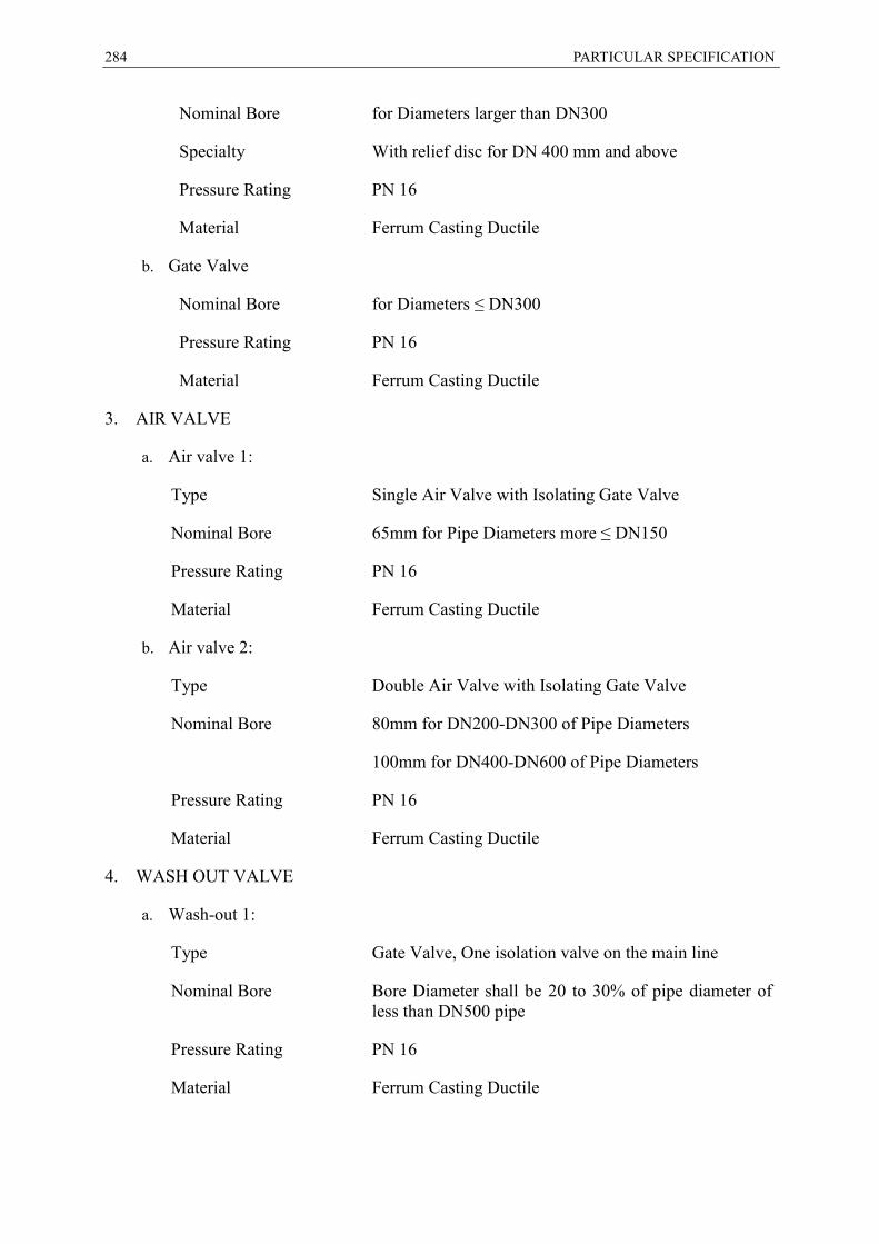
284 PARTICULAR SPECIFICATION
Nominal Bore for Diameters larger than DN300
Specialty With relief disc for DN 400 mm and above
Pressure Rating PN 16
Material Ferrum Casting Ductile
b. Gate Valve
Nominal Bore for Diameters ≤ DN300
Pressure Rating PN 16
Material Ferrum Casting Ductile
3. AIR VALVE
a. Air valve 1:
Type Single Air Valve with Isolating Gate Valve
Nominal Bore 65mm for Pipe Diameters more ≤ DN150
Pressure Rating PN 16
Material Ferrum Casting Ductile
b. Air valve 2:
Type Double Air Valve with Isolating Gate Valve
Nominal Bore 80mm for DN200-DN300 of Pipe Diameters
100mm for DN400-DN600 of Pipe Diameters
Pressure Rating PN 16
Material Ferrum Casting Ductile
4. WASH OUT VALVE
a. Wash-out 1:
Type Gate Valve, One isolation valve on the main line
Nominal Bore Bore Diameter shall be 20 to 30% of pipe diameter of less than DN500 pipe
Pressure Rating PN 16
Material Ferrum Casting Ductile

PARTICULAR SPECIFICATION 285
APPENDIX SOIL INVESTIGATION REPORT
Irbid City Drinking Water Network Proposed Project
S16000158-Rev.0-Interpretive Report
TABLE OF CONTENTS 1.0 INTRODUCTION ...................................................................................................................... 1
1.1 PURPOSE OF STUDY ............................................................................................................. 1
1.2 SCOPE OF WORK .................................................................................................................. 1
2.0 PROJECT AND SITE DESCRIPTION ...................................................................................... 1
3.0 GEOLOGY OF THE AREA ....................................................................................................... 4
3.1 QUATERNARY DEPOSITS (SOIL COVER) ................................................................................. 4
3.2 BELQA GROUP ...................................................................................................................... 4
Umm Rijam Formation (URC) ............................................................................... 4
Muwaqqar Chalk Marl Formation (MCM)............................................................... 4
Amman Silicified Limestone/Al-Hisa Phosphorite Formation (ASL/APH) ............... 4
Wadi Umm Ghudran Fromation (WG) ................................................................... 4
4.0 FIELD EXPLORATION AND IN-SITU TESTING ...................................................................... 6
4.1 DRILLING OF BOREHOLES ...................................................................................................... 6
4.2 SAMPLING OF BOREHOLES ..................................................................................................... 7
4.3 IN-SITU TESTING ................................................................................................................... 7
5.0 SUBSURFACE CONDITIONS ................................................................................................ 10
5.1 GROUND MATERIALS........................................................................................................... 10
5.2 GROUND WATER AND CAVITIES ........................................................................................... 11
6.0 LABORATORY TESTINGS .................................................................................................... 11
6.1 LIST OF LABORATORY TESTING ............................................................................................ 11
6.2 MATERIALS PHYSICAL PROPERTIES ..................................................................................... 12
6.3 MATERIAL CHEMICAL PROPERTIES ....................................................................................... 14
Sulphate Content ................................................................................................ 14
Chloride Content ................................................................................................. 15
pH Value ............................................................................................................. 16
7.0 CONCLUSIONS AND RECOMMENDATIONS ....................................................................... 16
7.1 PIPELINE RECOMMENDATIONS ............................................................................................. 16
7.2 EXCAVATION METHODS ....................................................................................................... 16
7.3 SIDE SLOPES RECOMMENDATIONS ...................................................................................... 17
7.4 SWELLING AND SHRINKAGE ................................................................................................. 17
7.5 DRAINAGE .......................................................................................................................... 18
7.6 BACKFILL MATERIAL AND COMPACTION CRITERIA ................................................................. 18
Selected Backfill Materials .................................................................................. 18
Retaining Walls (Filter Materials) ........................................................................ 18
Earth Pressure .................................................................................................... 18
8.0 STANDARD OF CARE ........................................................................................................... 19
9.0 ACES CONFIDENTIALITY & PROPRIETARY RIGHTS ........................................................ 19

Irbid City Drinking Water Network Proposed Project
S16000158-Rev.0-Interpretive Report
TABLE OF CONTENTS List of Figures Figure 1: Selected Site Photos ....................................................................................................... 1 Figure 2: General Location Map ..................................................................................................... 2 Figure 3: General Site Plan............................................................................................................. 3 Figure 4: General Geological Map .................................................................................................. 5 Figure 5: Drill Rig at the Site ........................................................................................................... 7 Figure 6: Standard Penetration Test (SPT) N-values vs. Depth ...................................................... 9 List of Tables Table 1: Boreholes Details (Coordinate System: Palestine 1923 / Palestine Belt) ........................... 6 Table 2: Standard Penetration Test Results ................................................................................... 8 Table 3: ASTM Standards for the Performed Laboratory Tests ..................................................... 11 Table 4: Classification and Index Tests Results ............................................................................ 12 Table 5: Chemical Test Results .................................................................................................... 14 Table 6: Excavation Methods ........................................................................................................ 17 Table 7: Selected Soil Parameters ................................................................................................ 19 Appendices Appendix A: Legend & Boreholes Logs Appendix B: Generalized Subsurface Profiles Appendix C: Laboratory Test Results Appendix D: Chemical Standards and Requirements
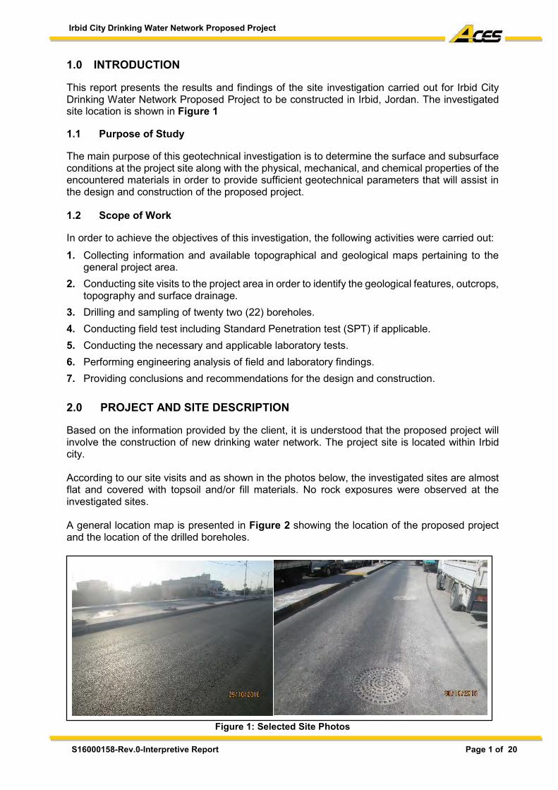
Irbid City Drinking Water Network Proposed Project
S16000158-Rev.0-Interpretive Report Page 1 of 20
1.0 INTRODUCTION
This report presents the results and findings of the site investigation carried out for Irbid City Drinking Water Network Proposed Project to be constructed in Irbid, Jordan. The investigated site location is shown in Figure 1 1.1 Purpose of Study
The main purpose of this geotechnical investigation is to determine the surface and subsurface conditions at the project site along with the physical, mechanical, and chemical properties of the encountered materials in order to provide sufficient geotechnical parameters that will assist in the design and construction of the proposed project. 1.2 Scope of Work
In order to achieve the objectives of this investigation, the following activities were carried out: 1. Collecting information and available topographical and geological maps pertaining to the
general project area. 2. Conducting site visits to the project area in order to identify the geological features, outcrops,
topography and surface drainage. 3. Drilling and sampling of twenty two (22) boreholes. 4. Conducting field test including Standard Penetration test (SPT) if applicable. 5. Conducting the necessary and applicable laboratory tests. 6. Performing engineering analysis of field and laboratory findings. 7. Providing conclusions and recommendations for the design and construction. 2.0 PROJECT AND SITE DESCRIPTION
Based on the information provided by the client, it is understood that the proposed project will involve the construction of new drinking water network. The project site is located within Irbid city. According to our site visits and as shown in the photos below, the investigated sites are almost flat and covered with topsoil and/or fill materials. No rock exposures were observed at the investigated sites. A general location map is presented in Figure 2 showing the location of the proposed project and the location of the drilled boreholes.
Figure 1: Selected Site Photos
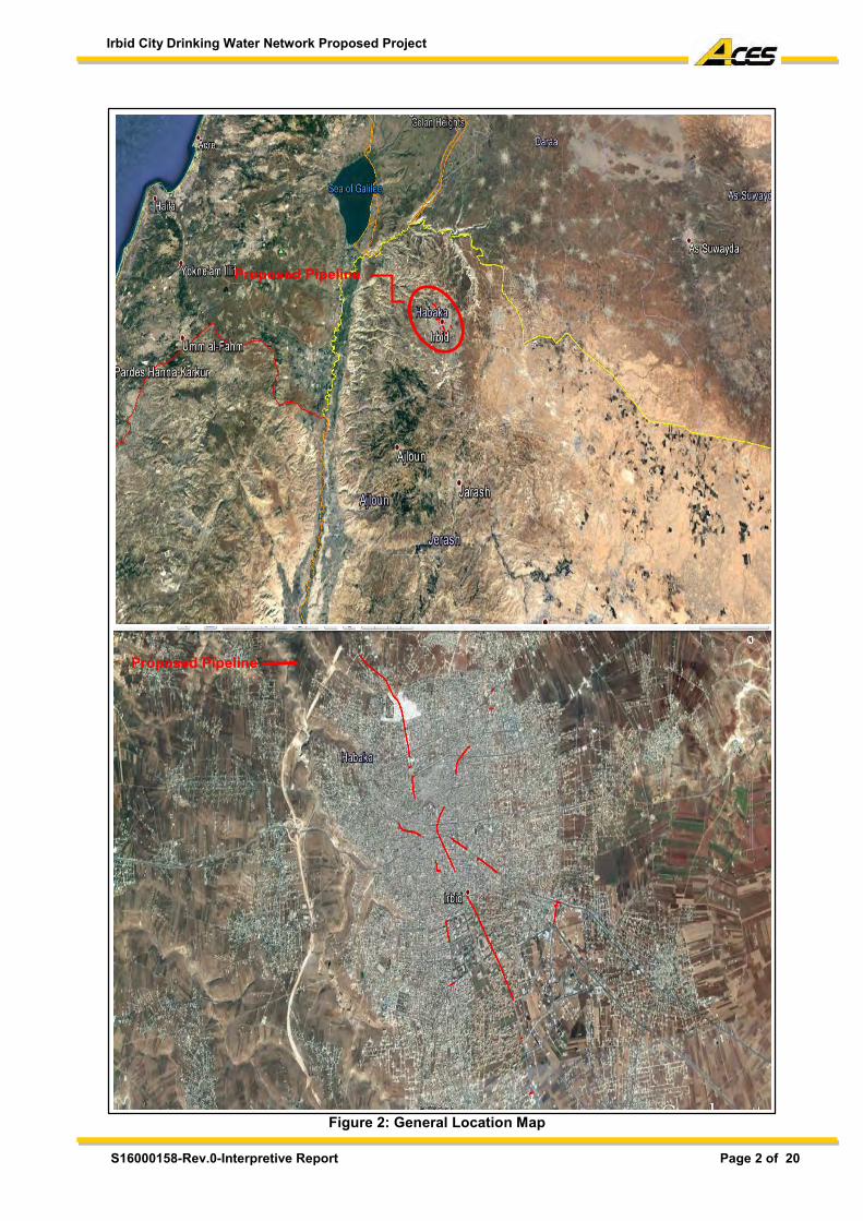
Irbid City Drinking Water Network Proposed Project
S16000158-Rev.0-Interpretive Report Page 2 of 20
Figure 2: General Location Map
Proposed Pipeline
Proposed Pipeline
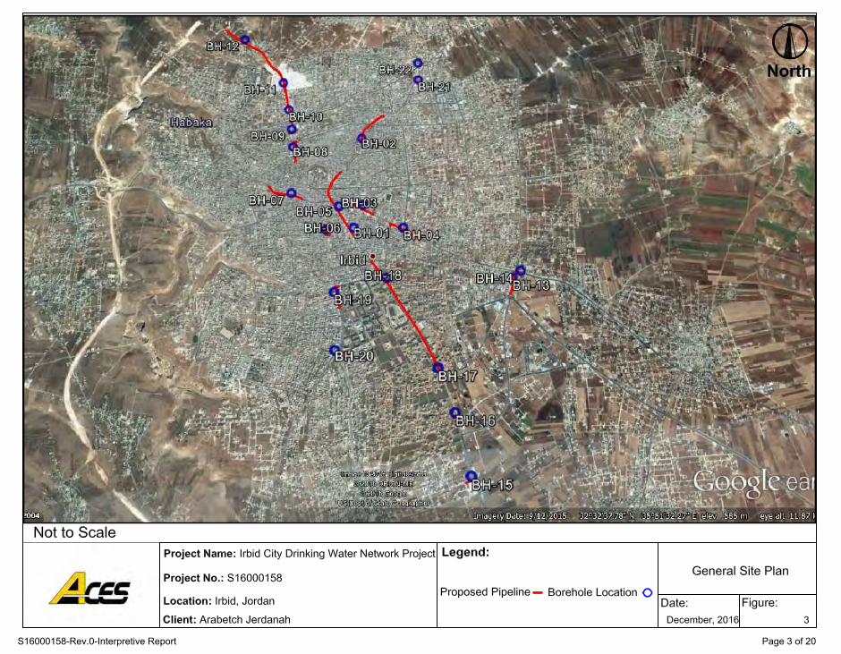
S16000158-Rev.0-Interpretive Report Page 3 of 20
Irbid City Drinking Water Network Proposed Project
S16000158-Rev.0-Interpretive Report Page 4 of 20
3.0 GEOLOGY OF THE AREA
According to the geological map (Irbid 3155-II) and as shown in Figure 4, the general project area belongs to late Cretaceous sedimentary rocks represented by Balqa Group and covered by Quaternary deposits. A brief description of these materials is provided below. 3.1 Quaternary Deposits (Soil Cover)
Pleistocene (plateau) gravel consists of poorly sorted, rounded to subrounded heterogeneous mixture of gravel with different sizes, mainly of limestone, phosphate and chert derived from the underlying and/or surrounding bedrock. 3.2 Belqa Group
Umm Rijam Formation (URC)
Covers most of the sheet area and is about 220m thick. It consists of the alternation of chalky limestone, marly limestone, and kerogenous limestone in its lower massive member.
Muwaqqar Chalk Marl Formation (MCM)
Ranges in thickness from 120m to 320m and consists of massive marly-chalky cliffs in its lower part, a sequence of alternating soft chalk and chalky limestone in its upper parts, and hard limestone concentrations within clayey marl towards its top.
Amman Silicified Limestone/Al-Hisa Phosphorite Formation (ASL/APH)
Consists of chert beds and concentrations with occasional berricated texture, limestone concentrations, laminated fossiliferous chalk which is rich in vertebrate remains. Megafossils include in the Al-Hisa Phosphotire formation which include baculites, bivalves, and Thalassinoides burrows.
Wadi Umm Ghudran Fromation (WG)
Wadi Umm Ghudran formation consists of two parts (lower and upper). The lower part consists of thinly bedded yellow to white grey locally pink grey, soft, massive chalky limestone while the upper part consists of limestone and chalky marl typically pink to yellow grey, hard, medium to thin bedded, fossiliferous to coquinal limestone with thin bands or concretions of chert, alternating with yellow to white grey chalky marl. This formation forms distinctive yellow to white grey gentle slopes between the underlying Wadi As Sir and the overlying Amman Silicified Formation. Additionally, the geological map also indicates that Several Faults may exist within the region of the project sites area, but these were not exposed at the surface due to superficial cover of recent deposits.

S16000158-Rev.0-Interpretive Report Page 5 of 20
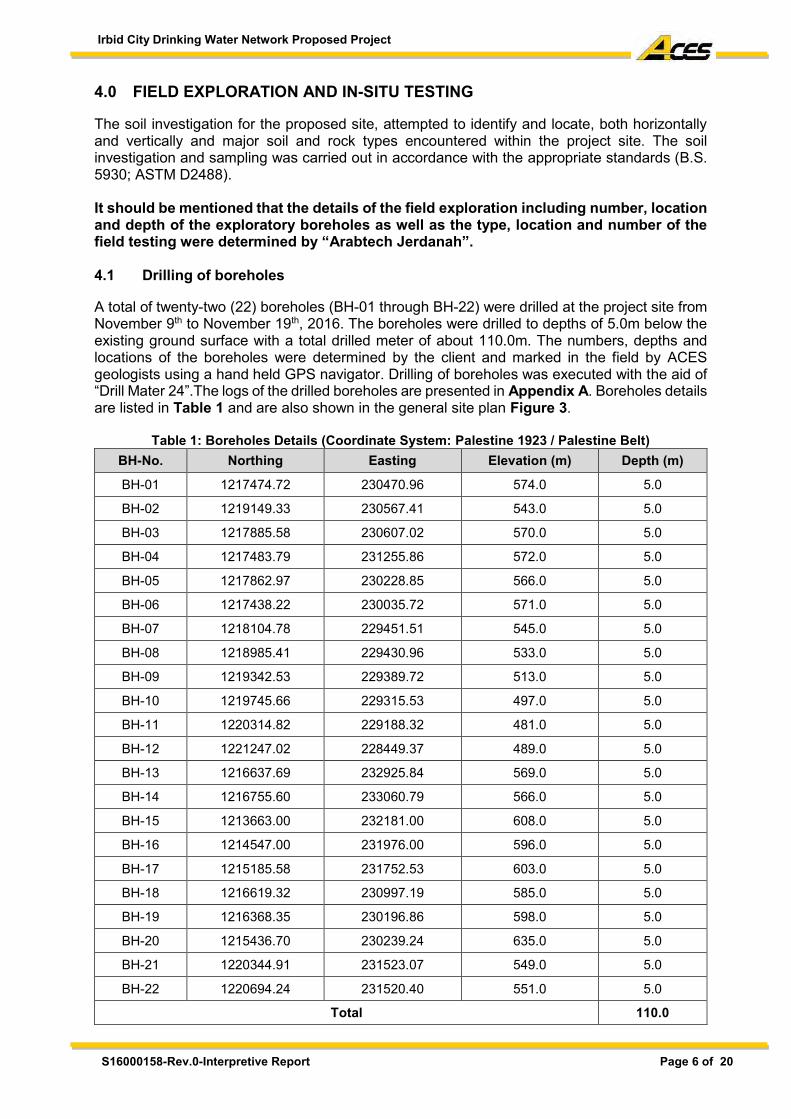
Irbid City Drinking Water Network Proposed Project
S16000158-Rev.0-Interpretive Report Page 6 of 20
4.0 FIELD EXPLORATION AND IN-SITU TESTING
The soil investigation for the proposed site, attempted to identify and locate, both horizontally and vertically and major soil and rock types encountered within the project site. The soil investigation and sampling was carried out in accordance with the appropriate standards (B.S. 5930; ASTM D2488). It should be mentioned that the details of the field exploration including number, location and depth of the exploratory boreholes as well as the type, location and number of the field testing were determined by “Arabtech Jerdanah”. 4.1 Drilling of boreholes
A total of twenty-two (22) boreholes (BH-01 through BH-22) were drilled at the project site from November 9th to November 19th, 2016. The boreholes were drilled to depths of 5.0m below the existing ground surface with a total drilled meter of about 110.0m. The numbers, depths and locations of the boreholes were determined by the client and marked in the field by ACES geologists using a hand held GPS navigator. Drilling of boreholes was executed with the aid of “Drill Mater 24”.The logs of the drilled boreholes are presented in Appendix A. Boreholes details are listed in Table 1 and are also shown in the general site plan Figure 3.
Table 1: Boreholes Details (Coordinate System: Palestine 1923 / Palestine Belt) BH-No. Northing Easting Elevation (m) Depth (m)
BH-01 1217474.72 230470.96 574.0 5.0
BH-02 1219149.33 230567.41 543.0 5.0
BH-03 1217885.58 230607.02 570.0 5.0
BH-04 1217483.79 231255.86 572.0 5.0
BH-05 1217862.97 230228.85 566.0 5.0
BH-06 1217438.22 230035.72 571.0 5.0
BH-07 1218104.78 229451.51 545.0 5.0
BH-08 1218985.41 229430.96 533.0 5.0
BH-09 1219342.53 229389.72 513.0 5.0
BH-10 1219745.66 229315.53 497.0 5.0
BH-11 1220314.82 229188.32 481.0 5.0
BH-12 1221247.02 228449.37 489.0 5.0
BH-13 1216637.69 232925.84 569.0 5.0
BH-14 1216755.60 233060.79 566.0 5.0
BH-15 1213663.00 232181.00 608.0 5.0
BH-16 1214547.00 231976.00 596.0 5.0
BH-17 1215185.58 231752.53 603.0 5.0
BH-18 1216619.32 230997.19 585.0 5.0
BH-19 1216368.35 230196.86 598.0 5.0
BH-20 1215436.70 230239.24 635.0 5.0
BH-21 1220344.91 231523.07 549.0 5.0
BH-22 1220694.24 231520.40 551.0 5.0
Total 110.0

Irbid City Drinking Water Network Proposed Project
S16000158-Rev.0-Interpretive Report Page 7 of 20
Figure 5: Drill Rig at the Site
4.2 Sampling of boreholes Due the nature of the encountered materials in all drilled boreholes, disturbed but representable soil samples were obtained in the encountered materials using the split spoon samplers (from SPT test). Percussion drilling techniques (down-the-hole hammer) were used at intervals where no SPT tests were carried out. Additional disturbed samples were obtained during this process. Note that the type and numbers of sampling methods were performed in accordance with the requirements of the Technical Specification provided by the client and based on the nature of the encountered strata. The recovered samples were examined, visually described by our geologists in accordance with appropriate standards (BS 5930; ASTM D2488), placed in waterproof plastic bags and taken to our laboratories for testing. 4.3 In-situ Testing
It should be mentioned that the type, number and location of the following field tests were determined by “Arabtech Jerdanah”. Standard Penetration Tests (SPT) were performed in all drilled boreholes in the encountered materials to obtain approximate dynamic resistance of the ground materials. The test was performed in accordance with ASTM D 1586-08-a. The SPT equipment used in this project consisted of an auto-trip hammer (63.5kg weight) and 45cm long split tube (5.0cm diameter) with a hammer drop of 760mm.
SPT penetration resistance value (N-value) is the number of blows required to achieve a penetration of 300mm below an initial seating drive of 15mm.The test was terminated when the number of blows recorded during the penetration in any of the 15cm increment reached 50 blows. Several empirical correlations have been established to relate the SPT blow counts (N) with relative density and friction angle for granular materials, and with consistency and undrained shear strength for cohesive materials. The definition of SPT and useful SPT correlations for granular and cohesive soils are presented in the legend to boring logs (Appendix A).
The SPT N-values in the tested materials ranged from 7.0 to refusal. However, the obtained N-values should be corrected for overburden and used equipment as follows:
𝑁1(60) = 𝑁 × 𝐶𝑁 × 𝐶𝐸
Where: 𝐶𝑁= Correction due to overburden pressure; 𝐶𝑁=10√1 𝜎𝑁⁄ (𝑘𝑁 𝑚2⁄ ), 𝜎𝑁=effective overburden pressure. Note that most of subject references do not consider correction of SPT N-values due to overburden at depths shallower than 5.0m. 𝐶𝐸= Correction due to hammer energy; CE =EMCBCSCR. Where:
Em is the energy ratio compared to 60%; ER/60. ER is equal to 60 for auto-trip hammers. CB is the borehole diameter correction, which is equal to 1.0 for the borehole diameter of
65-115mm.
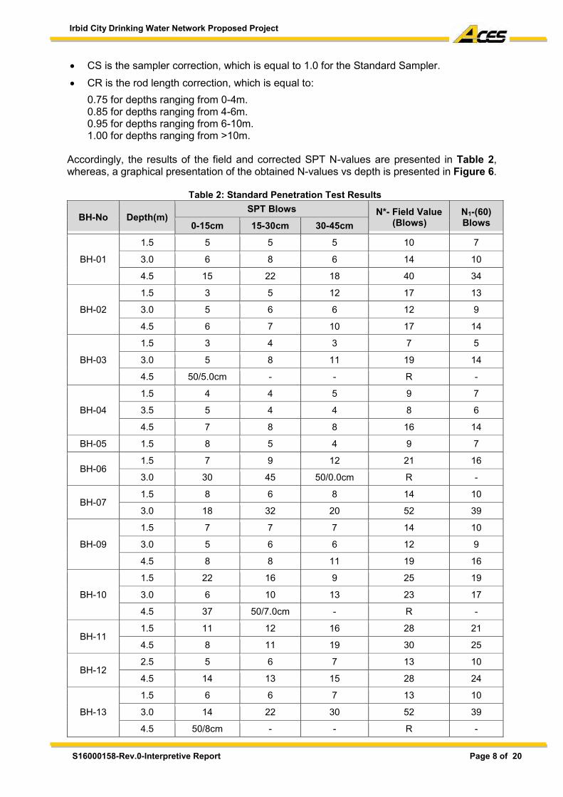
Irbid City Drinking Water Network Proposed Project
S16000158-Rev.0-Interpretive Report Page 8 of 20
CS is the sampler correction, which is equal to 1.0 for the Standard Sampler. CR is the rod length correction, which is equal to:
0.75 for depths ranging from 0-4m. 0.85 for depths ranging from 4-6m. 0.95 for depths ranging from 6-10m. 1.00 for depths ranging from >10m.
Accordingly, the results of the field and corrected SPT N-values are presented in Table 2, whereas, a graphical presentation of the obtained N-values vs depth is presented in Figure 6.
Table 2: Standard Penetration Test Results
BH-No Depth(m) SPT Blows N*- Field Value
(Blows) N1-(60) Blows 0-15cm 15-30cm 30-45cm
BH-01
1.5 5 5 5 10 7
3.0 6 8 6 14 10
4.5 15 22 18 40 34
BH-02
1.5 3 5 12 17 13
3.0 5 6 6 12 9
4.5 6 7 10 17 14
BH-03
1.5 3 4 3 7 5
3.0 5 8 11 19 14
4.5 50/5.0cm - - R -
BH-04
1.5 4 4 5 9 7
3.5 5 4 4 8 6
4.5 7 8 8 16 14
BH-05 1.5 8 5 4 9 7
BH-06 1.5 7 9 12 21 16
3.0 30 45 50/0.0cm R -
BH-07 1.5 8 6 8 14 10
3.0 18 32 20 52 39
BH-09
1.5 7 7 7 14 10
3.0 5 6 6 12 9
4.5 8 8 11 19 16
BH-10
1.5 22 16 9 25 19
3.0 6 10 13 23 17
4.5 37 50/7.0cm - R -
BH-11 1.5 11 12 16 28 21
4.5 8 11 19 30 25
BH-12 2.5 5 6 7 13 10
4.5 14 13 15 28 24
BH-13
1.5 6 6 7 13 10
3.0 14 22 30 52 39
4.5 50/8cm - - R -
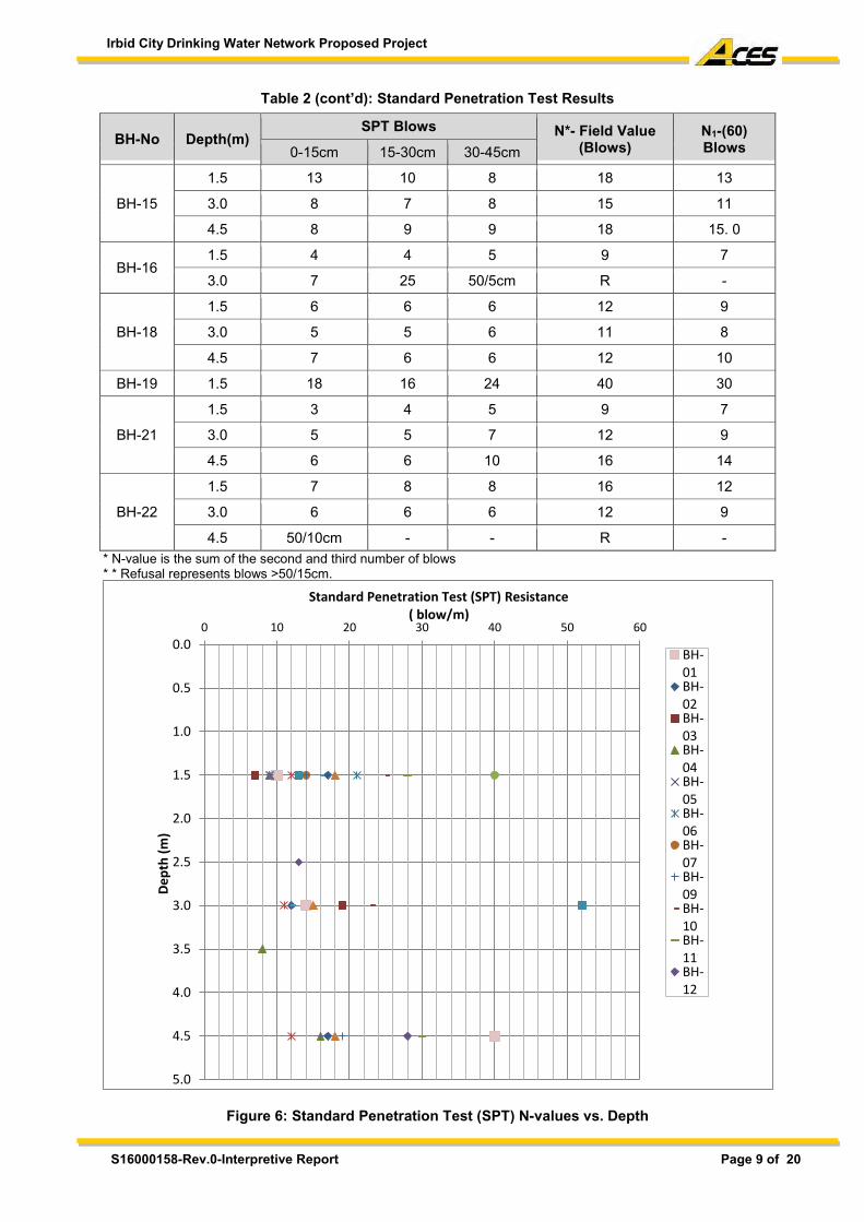
Irbid City Drinking Water Network Proposed Project
S16000158-Rev.0-Interpretive Report Page 9 of 20
Table 2 (cont’d): Standard Penetration Test Results
* N-value is the sum of the second and third number of blows * * Refusal represents blows >50/15cm.
Figure 6: Standard Penetration Test (SPT) N-values vs. Depth
0.0
0.5
1.0
1.5
2.0
2.5
3.0
3.5
4.0
4.5
5.0
0 10 20 30 40 50 60
De
pth
(m
)
Standard Penetration Test (SPT) Resistance( blow/m)
BH-01BH-02BH-03BH-04BH-05BH-06BH-07BH-09BH-10BH-11BH-12
BH-No Depth(m) SPT Blows N*- Field Value
(Blows) N1-(60) Blows 0-15cm 15-30cm 30-45cm
BH-15
1.5 13 10 8 18 13
3.0 8 7 8 15 11
4.5 8 9 9 18 15. 0
BH-16 1.5 4 4 5 9 7
3.0 7 25 50/5cm R -
BH-18
1.5 6 6 6 12 9
3.0 5 5 6 11 8
4.5 7 6 6 12 10
BH-19 1.5 18 16 24 40 30
BH-21
1.5 3 4 5 9 7
3.0 5 5 7 12 9
4.5 6 6 10 16 14
BH-22
1.5 7 8 8 16 12
3.0 6 6 6 12 9
4.5 50/10cm - - R -
Irbid City Drinking Water Network Proposed Project
S16000158-Rev.0-Interpretive Report Page 10 of 20
5.0 SUBSURFACE CONDITIONS
5.1 Ground Materials
The geological description of ground materials at the site and the approximate average depths at which they were encountered in the boreholes are presented in the boreholes logs (Appendix A) and are described below: Fill Materials Fill materials composed of brown silty clay with gravel and cobbles of limestone, chert, concrete, plastic and/or asphalt remains.This material was encountered at the location of all drilled boreholes except BH-04, BH-09, BH-14, and BH-22 with approximate thickness ranging from 0.5-3.0m below the existing ground surface. Buried Topsoil/Topsoil Materials Buried Topsoil and Topsoil materials composed of dark brown, silty clay with some scattered gravel of limestone and fragmented basalt. This material was encountered at the location of all drilled boreholes except BH-06, BH-17, and BH-20. The approximate thickness for both layers ranged from 0.5-1.5m below the existing ground surface or below the fill materials layer, which was encountered at the surface of the majority of the drilled boreholes. Silty Clay Stiff to hard, dark brown to reddish brown Silty Clay with some scattered gravel of limestone and patches of marl. This material was encountered at the location of all drilled boreholes except BH-05, BH-08, BH-11, BH-17, BH-19, and BH-20 with approximate thickness ranging from 1.0-4.5m below buried topsoil or topsoil materials layers and extends to the end of the drilled boreholes in most of the drilled boreholes. Mixture Materials Mixture materials composed of dense to very dense, dark brown, fragmented to disintegrated basalt with sandy silty clay intercalations. This material was encountered at the location of drilled boreholes (BH-03, BH-05, and BH-13) with approximate thickness ranging from 1.0-2.0m. Whereas at the location of drilled boreholes (BH-08, BH-16, and BH-20), the mixture materials layer composed of dense to very dense creamy, disintegrated chalky to clayey marl; brown, plastic silty clay; and thin highly fragmented chert (gravel to boulders sizes) with approximate thickness ranging from 1.0-2.0m. Silicified Limestone/Chert Grayish brown to black, strong to very strong, partly fractured, thick bedded chert; intercalated with white to grayish white, moderately weak to strong, partly micritic, silicified limestone. This material was encountered only at location of drilled boreholes (BH-17) with approximate thickness 4.2m below the fill materials and extended to the end of the drilled borehole. Clayey Marl to Marly Clay Creamy, stiff to very stiff, disintegrated, partly chalky, highly plastic, moist, Clayey Marl to Marly Clay. This material was encountered at location of drilled boreholes (BH-11 and BH-12) with approximate thickness of 4.0m below the buried topsoil materials and extended to the end of the drilled boreholes. Basalt Dark grey to black, highly weathered, fragmented (gravel, cobbles and boulder sizes) strong Basalt with silty clay intercalations. This material was encountered only at location of drilled borehole (BH-14) with approximate thickness of 3.5m below the silty clay layer and extends to the end of the drilled borehole.
Irbid City Drinking Water Network Proposed Project
S16000158-Rev.0-Interpretive Report Page 11 of 20
Chalky Marl Creamy, highly weathered to disintegrated, very weak Chalky Marl, intercalated with some thin nodular chert bands and some silty clay intercalations. This material was encountered only at BH-19 with approximate thickness of 2.5m below the buried topsoil materials. Intercalated Materials Intercalated materials composed of weak, creamy chalky marlstone; moderately weak, grayish yellow chalky limestone; strong, black thin bedded to nodular chert; and grayish to reddish brown, plastic, very weak marly clay. This material was encountered at location of drilled boreholes (BH-08, BH-19, BH-20, and BH-22) with approximate thickness ranging from 0.4-3.0m. The stratigraphical sequence of the boreholes are presented in the generalized subsurface profiles presented in Appendix B. 5.2 Ground Water and Cavities
No free ground water or cavities were encountered in any of the boreholes to the drilled depths during or after the completion of drilling activities. However, the surface hydrology is outside the scope of this study. 6.0 LABORATORY TESTINGS
6.1 List of Laboratory Testing
In order to identify the physical and chemical properties of the encountered materials. The following tests were performed (noting that limited number of tests were possible to be performed due the nature of encountered materials): 1. Classification and index test: moisture content, particle size distribution, and Atterberg limits. 2. Chemical tests: pH value, sulphate, and chloride. The tests were performed according to the relevant American Society for Testing and Materials (ASTM) Standards. Table 3 presents the applicable standards along with some photographs for these tests. The results of the physical and chemical tests are summarized in Table 4 and Table 5 whereas the test sheets are presented in Appendix C.
Table 3: ASTM Standards for the Performed Laboratory Tests No. Test Illustration ASTM
No. Title of Standard 1.0 Classification and Index Tests
1.1
Moi
stur
e C
onte
nt
D 2
216-
05
Standard Test Method for Laboratory Determination of Water (Moisture) Content of Soil and Rock by Mass
1.2
Atte
rber
g Li
mits
D 4
318-
10
Standard Test Methods for Liquid Limit, Plastic Limit, and Plasticity
Index of Soil
1.3
Parti
cle
Size
D 4
22-6
3 (2
007)
Standard Test Method for Particle-Size Analysis of Soils
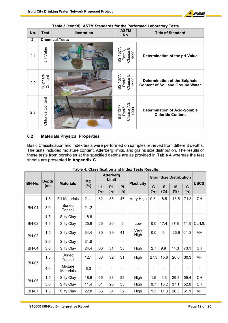
Irbid City Drinking Water Network Proposed Project
S16000158-Rev.0-Interpretive Report Page 12 of 20
Table 3 (cont’d): ASTM Standards for the Performed Laboratory Tests
No. Test Illustration ASTM No. Title of Standard
2. Chemical Tests
2.1
pH V
alue
BS 1
377:
Pa
rt 3,
C
laus
e 9,
19
90
Determination of the pH Value
2.2
Sulp
hate
C
onte
nt
BS 1
377:
Pa
rt3,
Cla
use
5,
1990
Determination of the Sulphate Content of Soil and Ground Water
2.3
Chl
orid
e C
onte
nt
BS 1
377:
P
art3
, C
laus
e 7.
3,
1990
Determination of Acid-Soluble Chloride Content
6.2 Materials Physical Properties
Basic Classification and index tests were performed on samples retrieved from different depths. The tests included moisture content, Atterberg limits, and grains size distribution. The results of these tests from boreholes at the specified depths are as provided in Table 4 whereas the test sheets are presented in Appendix C.
Table 4: Classification and Index Tests Results
BH-No. Depth (m) Materials MC
(%)
Atterberg Limit
Plasticity Grain Size Distribution
USCS LL (%)
PL (%)
PI (%)
G (%)
S (%)
M (%)
C (%)
BH-01
1.5 Fill Materials 21.1 82 35 47 Very High 0.8 8.8 18.5 71.8 CH
3.0 Buried Topsoil 21.2 - - - - - - - - -
4.5 Silty Clay 18.8 - - - - - - - - -
BH-02 4.5 Silty Clay 25.9 25 20 5 Low 0.0 17.4 37.8 44.8 CL-ML
BH-03 1.5 Silty Clay 34.4 80 39 41 Very
High 0.0 9 26.9 64.0 MH
3.0 Silty Clay 31.8 - - - - - - - - -
BH-04 3.0 Silty Clay 24.4 66 31 35 High 2.7 9.9 14.3 73.1 CH
BH-05 1.5 Buried
Topsoil 12.1 63 32 31 High 27.3 15.8 26.6 30.3 MH
4.0 Mixture Materials 8.3 - - - - - - - - -
BH-06 1.5 Silty Clay 18.6 66 28 38 High 1.5 9.3 29.8 59.4 CH
3.0 Silty Clay 11.4 61 26 35 High 0.7 10.2 37.1 52.0 CH
BH-07 1.5 Silty Clay 22.0 66 34 32 High 1.3 11.3 26.3 61.1 MH
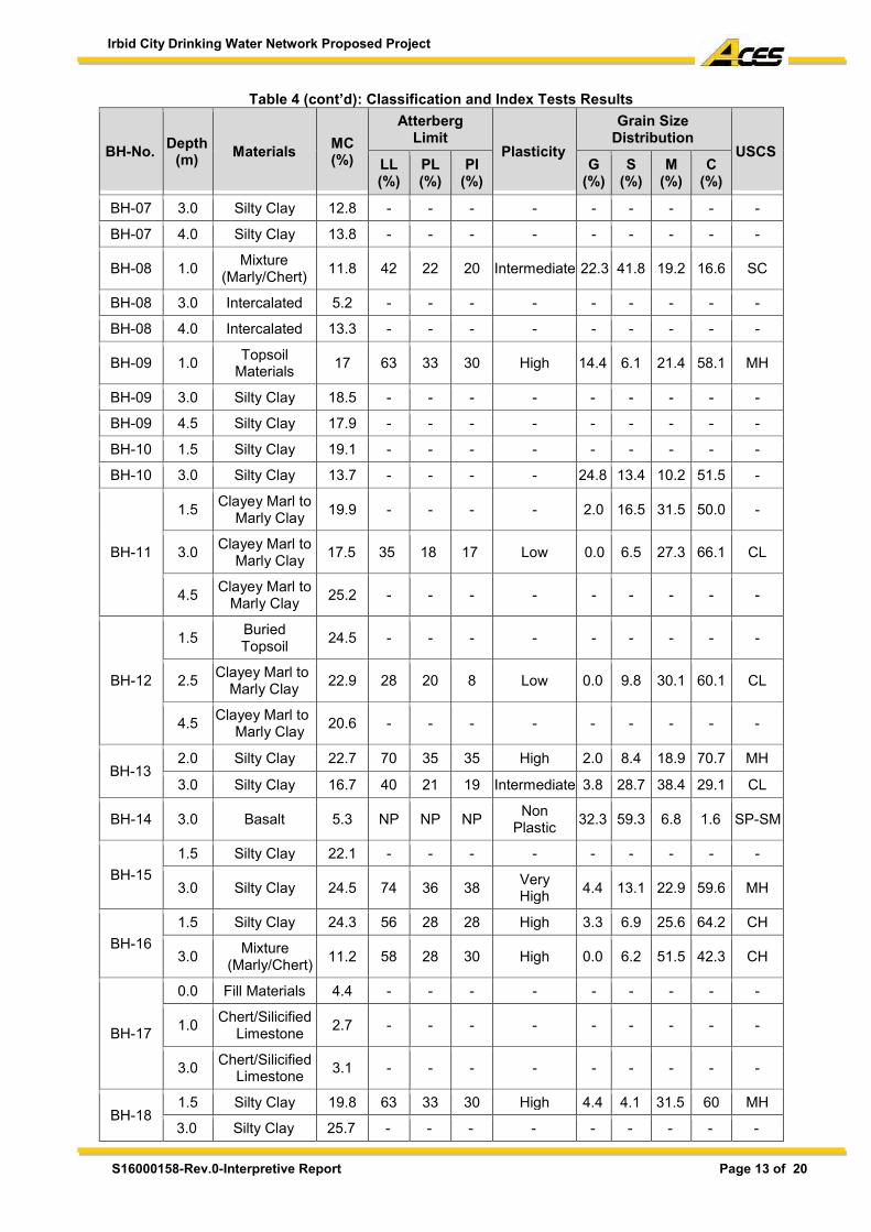
Irbid City Drinking Water Network Proposed Project
S16000158-Rev.0-Interpretive Report Page 13 of 20
Table 4 (cont’d): Classification and Index Tests Results
BH-No. Depth (m) Materials MC
(%)
Atterberg Limit
Plasticity
Grain Size Distribution
USCS LL (%)
PL (%)
PI (%)
G (%)
S (%)
M (%)
C (%)
BH-07 3.0 Silty Clay 12.8 - - - - - - - - -
BH-07 4.0 Silty Clay 13.8 - - - - - - - - -
BH-08 1.0 Mixture (Marly/Chert) 11.8 42 22 20 Intermediate 22.3 41.8 19.2 16.6 SC
BH-08 3.0 Intercalated 5.2 - - - - - - - - -
BH-08 4.0 Intercalated 13.3 - - - - - - - - -
BH-09 1.0 Topsoil Materials 17 63 33 30 High 14.4 6.1 21.4 58.1 MH
BH-09 3.0 Silty Clay 18.5 - - - - - - - - -
BH-09 4.5 Silty Clay 17.9 - - - - - - - - -
BH-10 1.5 Silty Clay 19.1 - - - - - - - - -
BH-10 3.0 Silty Clay 13.7 - - - - 24.8 13.4 10.2 51.5 -
BH-11
1.5 Clayey Marl to Marly Clay 19.9 - - - - 2.0 16.5 31.5 50.0 -
3.0 Clayey Marl to Marly Clay 17.5 35 18 17 Low 0.0 6.5 27.3 66.1 CL
4.5 Clayey Marl to Marly Clay 25.2 - - - - - - - - -
BH-12
1.5 Buried Topsoil 24.5 - - - - - - - - -
2.5 Clayey Marl to Marly Clay 22.9 28 20 8 Low 0.0 9.8 30.1 60.1 CL
4.5 Clayey Marl to Marly Clay 20.6 - - - - - - - - -
BH-13 2.0 Silty Clay 22.7 70 35 35 High 2.0 8.4 18.9 70.7 MH
3.0 Silty Clay 16.7 40 21 19 Intermediate 3.8 28.7 38.4 29.1 CL
BH-14 3.0 Basalt 5.3 NP NP NP Non Plastic 32.3 59.3 6.8 1.6 SP-SM
BH-15 1.5 Silty Clay 22.1 - - - - - - - - -
3.0 Silty Clay 24.5 74 36 38 Very High 4.4 13.1 22.9 59.6 MH
BH-16 1.5 Silty Clay 24.3 56 28 28 High 3.3 6.9 25.6 64.2 CH
3.0 Mixture (Marly/Chert) 11.2 58 28 30 High 0.0 6.2 51.5 42.3 CH
BH-17
0.0 Fill Materials 4.4 - - - - - - - - -
1.0 Chert/Silicified Limestone 2.7 - - - - - - - - -
3.0 Chert/Silicified Limestone 3.1 - - - - - - - - -
BH-18 1.5 Silty Clay 19.8 63 33 30 High 4.4 4.1 31.5 60 MH
3.0 Silty Clay 25.7 - - - - - - - - -
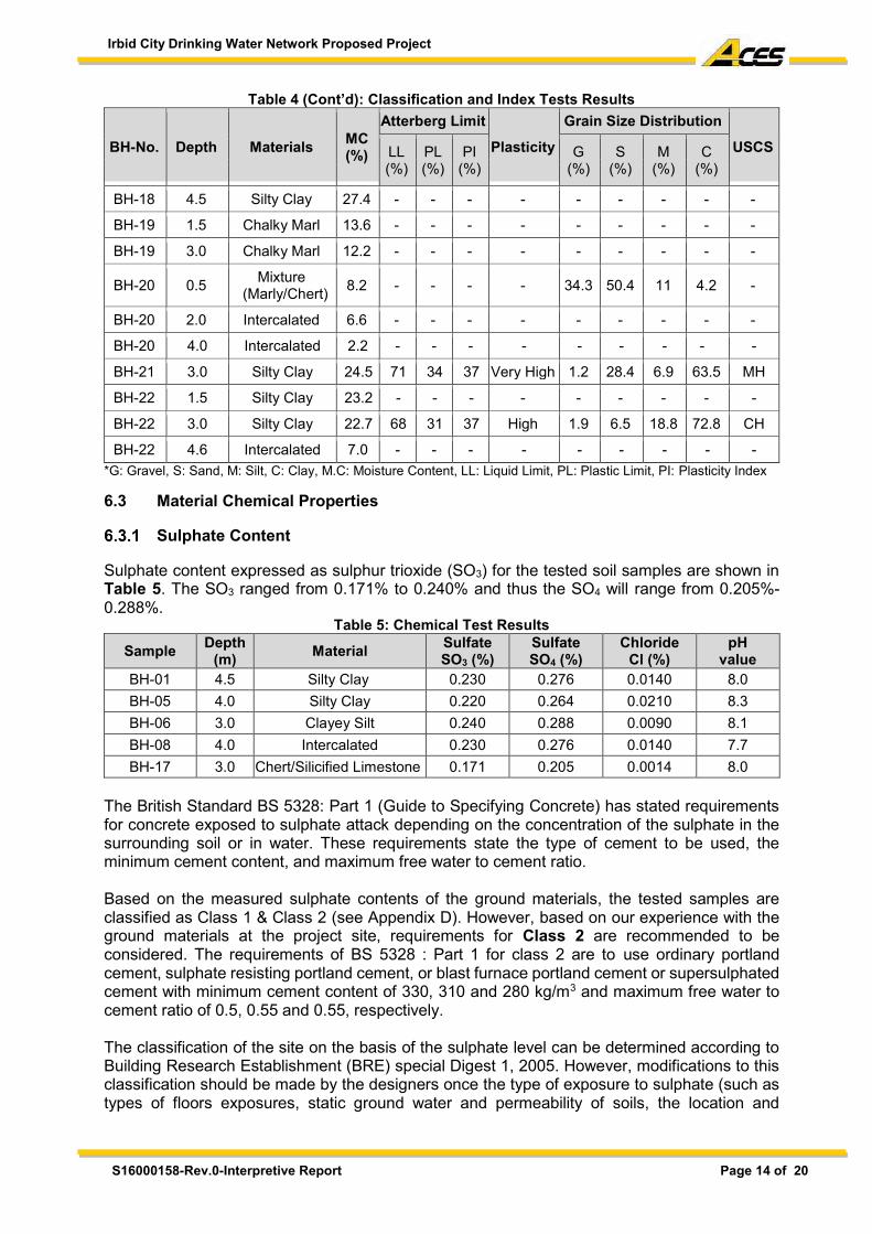
Irbid City Drinking Water Network Proposed Project
S16000158-Rev.0-Interpretive Report Page 14 of 20
Table 4 (Cont’d): Classification and Index Tests Results
BH-No. Depth Materials MC (%)
Atterberg Limit Plasticity
Grain Size Distribution USCS LL
(%) PL (%)
PI (%)
G (%)
S (%)
M (%)
C (%)
BH-18 4.5 Silty Clay 27.4 - - - - - - - - -
BH-19 1.5 Chalky Marl 13.6 - - - - - - - - -
BH-19 3.0 Chalky Marl 12.2 - - - - - - - - -
BH-20 0.5 Mixture (Marly/Chert) 8.2 - - - - 34.3 50.4 11 4.2 -
BH-20 2.0 Intercalated 6.6 - - - - - - - - -
BH-20 4.0 Intercalated 2.2 - - - - - - - - -
BH-21 3.0 Silty Clay 24.5 71 34 37 Very High 1.2 28.4 6.9 63.5 MH
BH-22 1.5 Silty Clay 23.2 - - - - - - - - -
BH-22 3.0 Silty Clay 22.7 68 31 37 High 1.9 6.5 18.8 72.8 CH
BH-22 4.6 Intercalated 7.0 - - - - - - - - - *G: Gravel, S: Sand, M: Silt, C: Clay, M.C: Moisture Content, LL: Liquid Limit, PL: Plastic Limit, PI: Plasticity Index 6.3 Material Chemical Properties
Sulphate Content
Sulphate content expressed as sulphur trioxide (SO3) for the tested soil samples are shown in Table 5. The SO3 ranged from 0.171% to 0.240% and thus the SO4 will range from 0.205%-0.288%.
Table 5: Chemical Test Results Sample Depth
(m) Material Sulfate SO3 (%)
Sulfate SO4 (%)
Chloride Cl (%)
pH value
BH-01 4.5 Silty Clay 0.230 0.276 0.0140 8.0 BH-05 4.0 Silty Clay 0.220 0.264 0.0210 8.3 BH-06 3.0 Clayey Silt 0.240 0.288 0.0090 8.1 BH-08 4.0 Intercalated 0.230 0.276 0.0140 7.7 BH-17 3.0 Chert/Silicified Limestone 0.171 0.205 0.0014 8.0
The British Standard BS 5328: Part 1 (Guide to Specifying Concrete) has stated requirements for concrete exposed to sulphate attack depending on the concentration of the sulphate in the surrounding soil or in water. These requirements state the type of cement to be used, the minimum cement content, and maximum free water to cement ratio. Based on the measured sulphate contents of the ground materials, the tested samples are classified as Class 1 & Class 2 (see Appendix D). However, based on our experience with the ground materials at the project site, requirements for Class 2 are recommended to be considered. The requirements of BS 5328 : Part 1 for class 2 are to use ordinary portland cement, sulphate resisting portland cement, or blast furnace portland cement or supersulphated cement with minimum cement content of 330, 310 and 280 kg/m3 and maximum free water to cement ratio of 0.5, 0.55 and 0.55, respectively. The classification of the site on the basis of the sulphate level can be determined according to Building Research Establishment (BRE) special Digest 1, 2005. However, modifications to this classification should be made by the designers once the type of exposure to sulphate (such as types of floors exposures, static ground water and permeability of soils, the location and
Irbid City Drinking Water Network Proposed Project
S16000158-Rev.0-Interpretive Report Page 15 of 20
thickness of the structure and the hydrostatic head), and the types of concrete used (such as precast concrete, cast-in-situ concrete, wall units, piles, etc.) are finally determined. It should be noted however, that practical experience has indicated that mixes having both the minimum cement content and maximum free water to cement ratio recommended above may results in concrete of low level of workability. Such that full compaction to achieve dense concrete of the necessary degree of impermeability to resist, as much possible chemical attach, cannot be easily achieved. It may be therefore, practical to increase the cement content while maintaining the recommended water to cement ratio in order to obtain the appropriate workability to achieve full compaction of the concrete. Alternatively, workability/compaction can be enhanced by using a plasticizing or superplasticizing admixture. The admixture should comply with BS 5075 Parts 1 and 3. Admixtures containing calcium chloride are not recommended for sulphate resisting, or any reinforced concrete. The CIRIA Guide to Concrete Construction in the Gulf region, (CIRIA-C577-2002), recommended maximum limit of sulphates as SO3 in the coarse or fine aggregates used for concrete as 0.4% and recommended maximum limits for total sulphate content in concrete from all sources expressed as a percentage by weight of cement as 4% in all cases. It is our opinion that these limits must be adopted and specified for contamination of the concrete and its ingredients in order to achieve durable concrete. Concrete cast in the ground will cure under the conditions normally favored for strength development and durability provided that the temperature rise due to the heat of hydration kept low. In the particular case of resistance to sulphate attack, a period or air curing to the structure has been shown to provide a protective layer associated by allowing the access of air to a dry concrete surface for several weeks after the normal curing schedules (BRE special Digest 1, 2005). It is emphasized however, that since good curing entails keeping the surface wet, the subsequent treatment of dry surface should be regard as a specific secondary process.
Chloride Content
The chloride content for the tested soil samples are also presented in Table 5. The chloride content in the tested soil samples ranged from 0.0014% to 0.0210%. There is no widely accepted view on the concentration which chlorides become significant in soil or groundwater, but limited experience in the region suggests it may be as low as 0.05% (CIRIA Guide, 2002). However, it is important to ensure that the maximum limits for chlorides and sulphates in the aggregate components and in the concrete, are not exceeded. As shown in Table 5, chloride content in all tested samples is lower than 0.05%. Therefore, it is advisable that concrete cover for steel reinforcement be increased (to be 4 - 5 cm) in the buried members to protect the steel from the ingress of the chlorides present in the surrounding environment. Surface protection and sealing of the concrete and any steel elements should also be considered. Chlorides do not react expansively with Portland cement as do sulphate. Their effect when present in concrete is to increase the risk of corrosion of embedded metals of which the greatest volume used is steel reinforcement. They can be tolerated in plain concrete, although when present in large amount some surface dampness may result, but widespread and serious damage has been caused by the use of chloride-contaminated aggregates in reinforced concrete. The corrosion products occupy more than twice the volume of steel, and their formation can be accompanied by very high tensile pressures as great, resulting in cracking of the concrete, frequently followed by spalling of the cover. In severe cases of corrosion there may be a reduction in section of the reinforcing bars, leading to a loss of tensile strength of the concrete. The CIRIA guide to concrete construction in the Gulf region (2002) recommended maximum limit of chlorides as Cl in the coarse and fine aggregates used for concrete as 0.03% and 0.06%, respectively, and recommended maximum limits for total chloride content in concrete from all
Irbid City Drinking Water Network Proposed Project
S16000158-Rev.0-Interpretive Report Page 16 of 20
sources expressed as a percentage by weight of cement as 0.15% for reinforced concrete made with portland cements containing less than about 4% C3A (e.g. sulphate resisting portland cement) and 0.30% for reinforced concrete made with portland cements containing 4% or more C3A (OPC and ASTM type I and II usually contain more than 4% C3A). For un-reinforced concrete the limit is 0.6%.
pH Value
The measured pH values indicate that all foundation soils are slightly alkaline, (i.e. pH values are higher than 7 and less than 9.5). These values are considered not detrimental to steel. 7.0 CONCLUSIONS AND RECOMMENDATIONS
Kindly note no specific information provided by the client on any services structures/buildings to be constructed at the project site. Accordingly, the following general recommendations are given based on field investigation and laboratory test results, surface and subsurface conditions and practical experience. 7.1 Pipeline Recommendations
The proposed drinking water network will be fully buried in trenches along the investigated area. Accordingly, the pipeline would likely bear on the natural soil/rock layers (Silty Clay, Mixture Materials, Mixture Materials (Marl/Chert), Clayey Marl to Marly Clay, Chert/Silicified Limestone, Chalky Marl, Basalt, Intercalated materials) which are characterized by large variation in composition and strength parameters in both horizontal and vertical extends. In addition, the whole length of the pipeline shall be erected on a 10cm thick fine sand matrix. Regardless, pipeline should never be laid directly on the existing topsoil and fill materials encountered at the surface of all drilled boreholes. Pipelines often become distorted because of differential swelling and shrinkage of soils. Accordingly, it is recommended either to use flexible pipe materials (e.g, steel pipes), or use flexible joints to avoid developing large shear or flexural stresses. The best solution is to use both, i.e. flexible pipes with flexible joints. Furthermore, pipelines excavations should not be exposed for a long period neither to the sun nor to the rainfall. After pipelines construction, the excavations should be filled and compacted in layers of 20 cm thick. It is also recommended to avoid planting deep root trees in order to minimize seasoned variation in moisture content of ground materials under the proposed structures. The effect of trees can be noticed as trees reach a height approximately equal to their distance away from any structure. Therefore, if any trees are to be planted, they should be located away from any structure by distance at least equal to their expected maximum height. 7.2 Excavation Methods It is expected that the excavation will be carried out through the (Topsoil, Buried Topsoil, Fill Materials, Silty Clay, Mixture Materials, Mixture Materials (Marl/Chert), Clayey Marl to Marly Clay, Chert/Silicified Limestone, Chalky Marl, Basalt, Intercalated Materials). Therefore, pneumatic equipment such as jackhammer will be needed in addition to the conventional excavation equipment such as loaders and backhoes (JCB) for excavation work at the site. Table 6 summarizes the proper excavation methods that could be used for excavating the encountered materials at the project site.
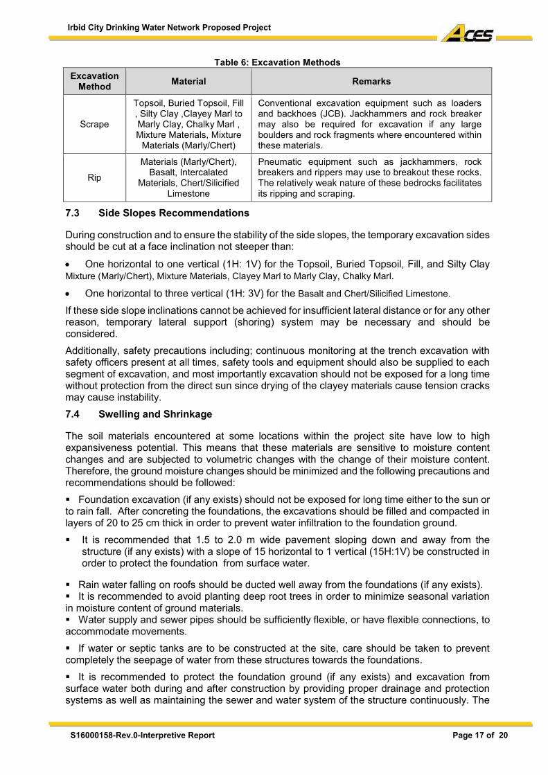
Irbid City Drinking Water Network Proposed Project
S16000158-Rev.0-Interpretive Report Page 17 of 20
Table 6: Excavation Methods
Excavation Method Material Remarks
Scrape
Topsoil, Buried Topsoil, Fill , Silty Clay ,Clayey Marl to Marly Clay, Chalky Marl , Mixture Materials, Mixture
Materials (Marly/Chert)
Conventional excavation equipment such as loaders and backhoes (JCB). Jackhammers and rock breaker may also be required for excavation if any large boulders and rock fragments where encountered within these materials.
Rip
Materials (Marly/Chert), Basalt, Intercalated
Materials, Chert/Silicified Limestone
Pneumatic equipment such as jackhammers, rock breakers and rippers may use to breakout these rocks. The relatively weak nature of these bedrocks facilitates its ripping and scraping.
7.3 Side Slopes Recommendations
During construction and to ensure the stability of the side slopes, the temporary excavation sides should be cut at a face inclination not steeper than:
One horizontal to one vertical (1H: 1V) for the Topsoil, Buried Topsoil, Fill, and Silty Clay Mixture (Marly/Chert), Mixture Materials, Clayey Marl to Marly Clay, Chalky Marl.
One horizontal to three vertical (1H: 3V) for the Basalt and Chert/Silicified Limestone.
If these side slope inclinations cannot be achieved for insufficient lateral distance or for any other reason, temporary lateral support (shoring) system may be necessary and should be considered.
Additionally, safety precautions including; continuous monitoring at the trench excavation with safety officers present at all times, safety tools and equipment should also be supplied to each segment of excavation, and most importantly excavation should not be exposed for a long time without protection from the direct sun since drying of the clayey materials cause tension cracks may cause instability.
7.4 Swelling and Shrinkage
The soil materials encountered at some locations within the project site have low to high expansiveness potential. This means that these materials are sensitive to moisture content changes and are subjected to volumetric changes with the change of their moisture content. Therefore, the ground moisture changes should be minimized and the following precautions and recommendations should be followed:
Foundation excavation (if any exists) should not be exposed for long time either to the sun or to rain fall. After concreting the foundations, the excavations should be filled and compacted in layers of 20 to 25 cm thick in order to prevent water infiltration to the foundation ground.
It is recommended that 1.5 to 2.0 m wide pavement sloping down and away from the structure (if any exists) with a slope of 15 horizontal to 1 vertical (15H:1V) be constructed in order to protect the foundation from surface water.
Rain water falling on roofs should be ducted well away from the foundations (if any exists). It is recommended to avoid planting deep root trees in order to minimize seasonal variation in moisture content of ground materials. Water supply and sewer pipes should be sufficiently flexible, or have flexible connections, to accommodate movements.
If water or septic tanks are to be constructed at the site, care should be taken to prevent completely the seepage of water from these structures towards the foundations.
It is recommended to protect the foundation ground (if any exists) and excavation from surface water both during and after construction by providing proper drainage and protection systems as well as maintaining the sewer and water system of the structure continuously. The
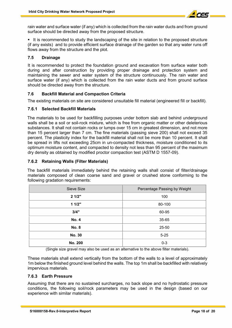
Irbid City Drinking Water Network Proposed Project
S16000158-Rev.0-Interpretive Report Page 18 of 20
rain water and surface water (if any) which is collected from the rain water ducts and from ground surface should be directed away from the proposed structure.
It is recommended to study the landscaping of the site in relation to the proposed structure (if any exists) and to provide efficient surface drainage of the garden so that any water runs off flows away from the structure and the plot. 7.5 Drainage
It is recommended to protect the foundation ground and excavation from surface water both during and after construction by providing proper drainage and protection system and maintaining the sewer and water system of the structure continuously. The rain water and surface water (if any) which is collected from the rain water ducts and from ground surface should be directed away from the structure. 7.6 Backfill Material and Compaction Criteria The existing materials on site are considered unsuitable fill material (engineered fill or backfill).
Selected Backfill Materials The materials to be used for backfilling purposes under bottom slab and behind underground walls shall be a soil or soil-rock mixture, which is free from organic matter or other deleterious substances. It shall not contain rocks or lumps over 15 cm in greatest dimension, and not more than 15 percent larger than 7 cm. The fine materials (passing sieve 200) shall not exceed 35 percent. The plasticity index for the backfill material shall not be more than 10 percent. It shall be spread in lifts not exceeding 25cm in un-compacted thickness, moisture conditioned to its optimum moisture content, and compacted to density not less than 95 percent of the maximum dry density as obtained by modified proctor compaction test (ASTM D 1557-09).
Retaining Walls (Filter Materials) The backfill materials immediately behind the retaining walls shall consist of filter/drainage materials composed of clean coarse sand and gravel or crushed stone conforming to the following gradation requirements:
Sieve Size Percentage Passing by Weight
2 1/2" 100
1 1/2" 80-100
3/4" 60-95
No. 4 35-65
No. 8 25-50
No. 30 5-25
No. 200 0-3 (Single size gravel may also be used as an alternative to the above filter materials).
These materials shall extend vertically from the bottom of the walls to a level of approximately 1m below the finished ground level behind the walls. The top 1m shall be backfilled with relatively impervious materials.
Earth Pressure
Assuming that there are no sustained surcharges, no back slope and no hydrostatic pressure conditions, the following soil/rock parameters may be used in the design (based on our experience with similar materials).
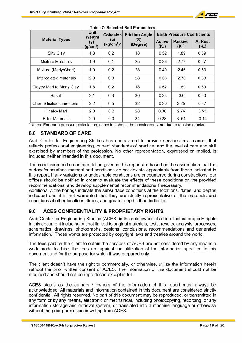
Irbid City Drinking Water Network Proposed Project
S16000158-Rev.0-Interpretive Report Page 19 of 20
Table 7: Selected Soil Parameters
Material Types Unit
Weight (γ)
(g/cm3)
Cohesion (c)
(kg/cm2)*
Friction Angle ()
(Degree)
Earth Pressure Coefficients Active
(Ka) Passive
(Kp) At Rest
(Ko) Silty Clay 1.8 0.2 18 0.52 1.89 0.69
Mixture Materials 1.9 0.1 25 0.36 2.77 0.57
Mixture (Marly/Chert) 1.9 0.2 28 0.40 2.46 0.53
Intercalated Materials 2.0 0.3 28 0.36 2.76 0.53
Clayey Marl to Marly Clay 1.8 0.2 18 0.52 1.89 0.69
Basalt 2.1 0.3 30 0.33 3.0 0.50
Chert/Silicified Limestone 2.2 0.5 32 0.30 3.25 0.47
Chalky Marl 2.0 0.2 28 0.36 2.76 0.53
Filter Materials 2.0 0.0 34 0.28 3 .54 0.44 *Notes: For earth pressure calculation, cohesion should be considered zero due to tension cracks.
8.0 STANDARD OF CARE Arab Center for Engineering Studies has endeavored to provide services in a manner that reflects professional engineering, current standards of practice, and the level of care and skill exercised by members of the profession. No other representation, expressed or implied, is included neither intended in this document. The conclusion and recommendation given in this report are based on the assumption that the surface/subsurface material and conditions do not deviate appreciably from those indicated in this report. If any variations or undesirable conditions are encountered during constructions, our offices should be notified in order to evaluate the effects of these conditions on the provided recommendations, and develop supplemental recommendations if necessary. Additionally, the borings indicate the subsurface conditions at the locations, dates, and depths indicated and it is not warranted that they are strictly representative of the materials and conditions at other locations, times, and greater depths than indicated. 9.0 ACES CONFIDENTIALITY & PROPRIETARY RIGHTS Arab Center for Engineering Studies (ACES) is the sole owner of all intellectual property rights in this document including but not limited to original materials, tests, results, analysis, processes, schematics, drawings, photographs, designs, conclusions, recommendations and generated information. Those works are protected by copyright laws and treaties around the world. The fees paid by the client to obtain the services of ACES are not considered by any means a work made for hire, the fees are against the utilization of the information specified in this document and for the purpose for which it was prepared only. The client doesn’t have the right to commercially, or otherwise, utilize the information herein without the prior written consent of ACES. The information of this document should not be modified and should not be reproduced except in full ACES status as the authors / owners of the information of this report must always be acknowledged. All materials and information contained in this document are considered strictly confidential. All rights reserved. No part of this document may be reproduced, or transmitted in any form or by any means, electronic or mechanical, including photocopying, recording, or any information storage and retrieval system, or translated into a machine language or otherwise without the prior permission in writing from ACES.
Irbid City Drinking Water Network Proposed Project
S16000158-Rev.0-Interpretive Report Page 20 of 20
Appendices Appendix A: Legend & Boreholes Logs Appendix B: Generalized subsurface profiles Appendix C: Laboratory Test Results Appendix D: Chemical Standards and Requirements
Irbid City Drinking Water Network Proposed Project
S16000158-Rev.0-Interpretive Report
Appendix A Legend & Boreholes Logs

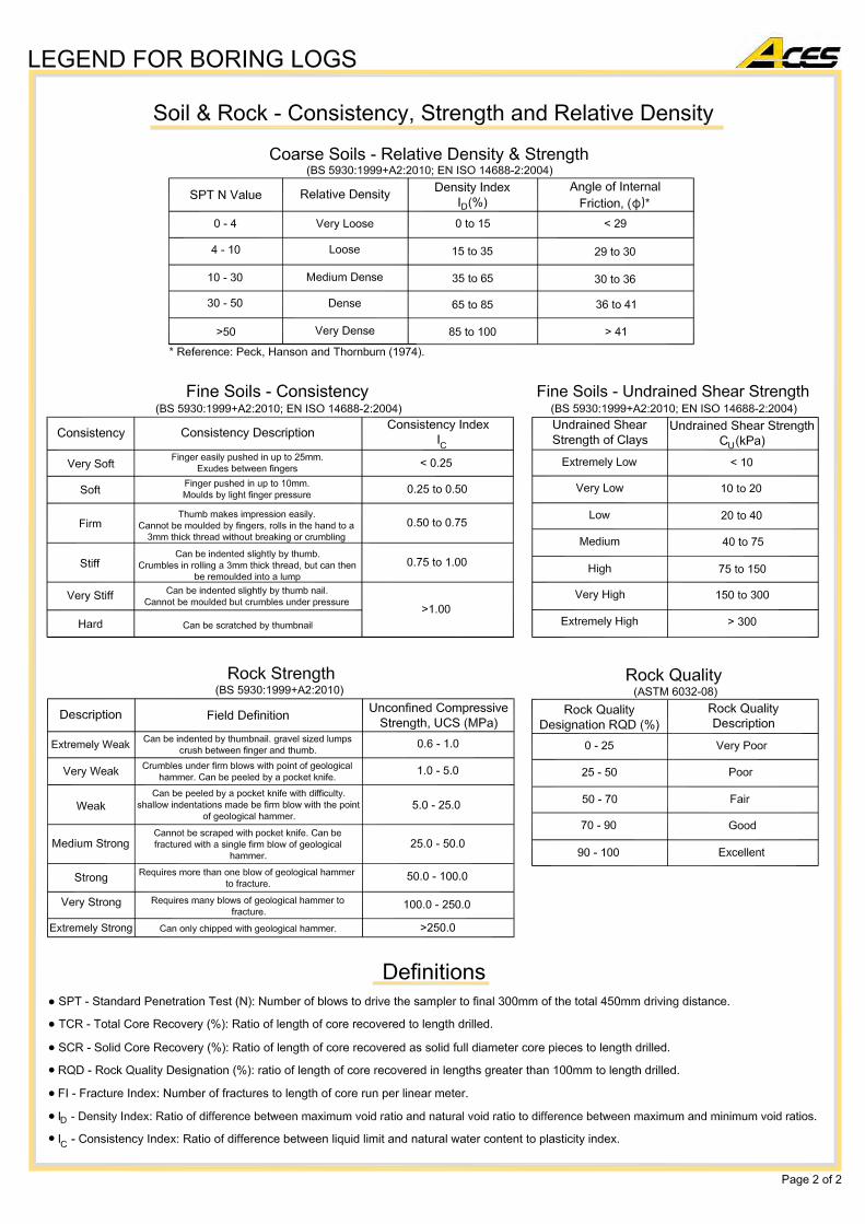
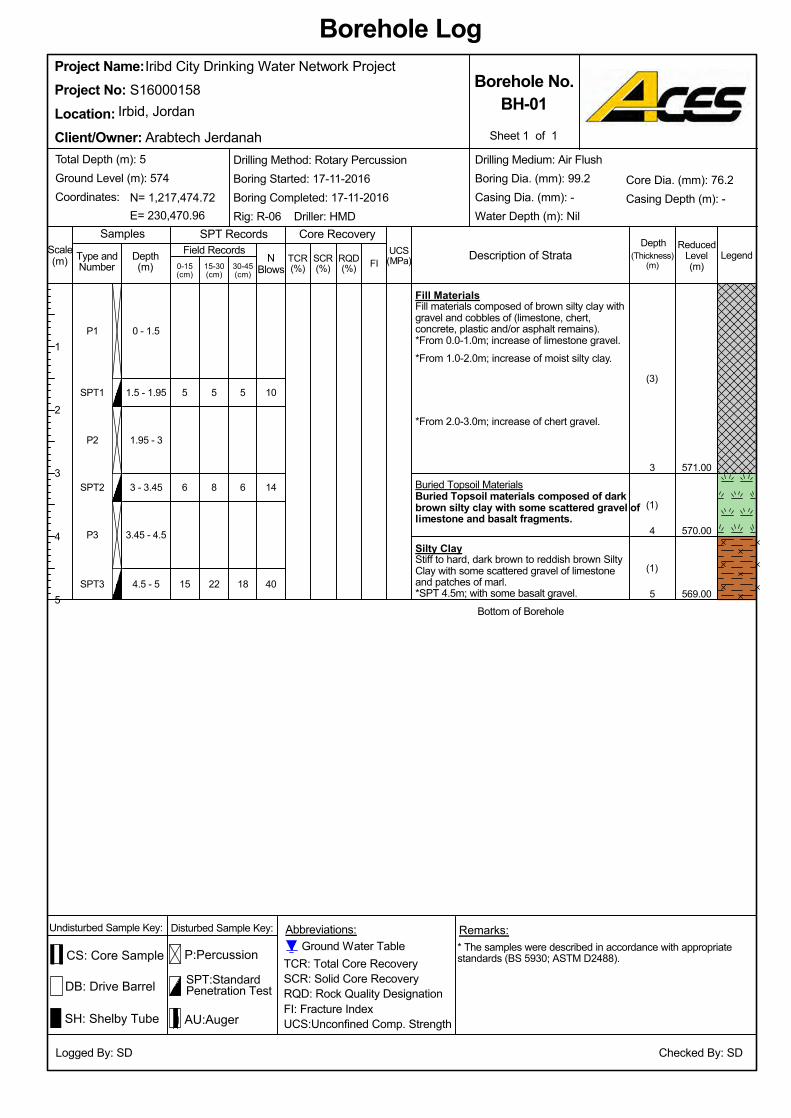
*From 2.0-3.0m; increase of chert gravel.
5
569.00
570.00
571.00
Bottom of Borehole
*SPT 4.5m; with some basalt gravel.4.5 - 5
Buried Topsoil MaterialsBuried Topsoil materials composed of darkbrown silty clay with some scattered gravel oflimestone and basalt fragments.
*From 1.0-2.0m; increase of moist silty clay.*From 0.0-1.0m; increase of limestone gravel.
Fill MaterialsFill materials composed of brown silty clay withgravel and cobbles of (limestone, chert,concrete, plastic and/or asphalt remains).
Silty ClayStiff to hard, dark brown to reddish brown SiltyClay with some scattered gravel of limestoneand patches of marl.
3.45 - 4.5
3 - 3.45
1.95 - 3
1.5 - 1.95
0 - 1.5
5
Iribd City Drinking Water Network Project
3
6
15 22
8
5
(1)
(1)
(3)
SPT2
SPT3
4
P2
SPT1
P1
P3
NBlows0-15
(cm)
ReducedLevel(m)
Description of Strata
Project Name:
Samples
SCR(%)
1
2
3
4
5
Logged By: SD
* The samples were described in accordance with appropriatestandards (BS 5930; ASTM D2488).
30-45(cm)
Arabtech Jerdanah
TCR(%)
Abbreviations:
Borehole Log
Core Recovery
(Thickness)(m)
LegendUCS(MPa)
DB: Drive Barrel
15-30(cm)
P:Percussion
SPT:StandardPenetration Test
SPT RecordsScale(m) RQD
(%)
Checked By: SD
SH: Shelby Tube
N= 1,217,474.72
Irbid, Jordan
Client/Owner:
Depth(m)
TCR: Total Core RecoverySCR: Solid Core RecoveryRQD: Rock Quality DesignationFI: Fracture IndexUCS:Unconfined Comp. Strength
Sheet 1 of 1
E= 230,470.96
40
14
10
18
6
5
Borehole No.BH-01
S16000158
Location:Project No:
FI
Depth
Drilling Method: Rotary PercussionBoring Started: 17-11-2016Boring Completed: 17-11-2016Rig: R-06 Driller: HMD
Type andNumber
Total Depth (m): 5Ground Level (m): 574Coordinates:
Undisturbed Sample Key: Disturbed Sample Key: Remarks:
Field Records
CS: Core Sample
AU:Auger
Ground Water Table
Core Dia. (mm): 76.2Casing Depth (m): -
Drilling Medium: Air FlushBoring Dia. (mm): 99.2Casing Dia. (mm): -Water Depth (m): Nil
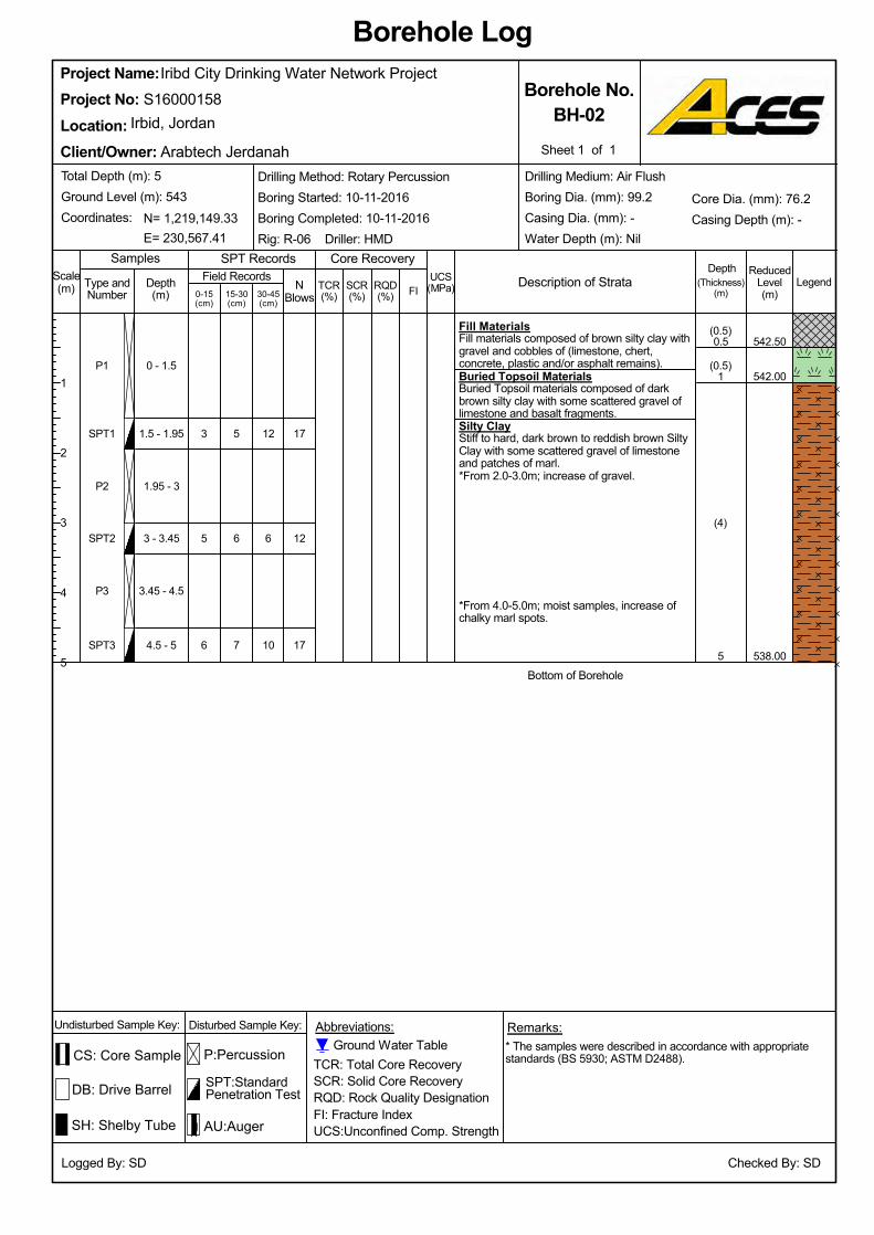
Silty ClayStiff to hard, dark brown to reddish brown SiltyClay with some scattered gravel of limestoneand patches of marl.
3
538.00
542.00
542.50
Bottom of Borehole
6
*From 2.0-3.0m; increase of gravel.
Buried Topsoil MaterialsBuried Topsoil materials composed of darkbrown silty clay with some scattered gravel oflimestone and basalt fragments.
Fill MaterialsFill materials composed of brown silty clay withgravel and cobbles of (limestone, chert,concrete, plastic and/or asphalt remains).
SPT3
*From 4.0-5.0m; moist samples, increase ofchalky marl spots.
4.5 - 5
3.45 - 4.5
3 - 3.45
1.95 - 3
1.5 - 1.95
0 - 1.5
Iribd City Drinking Water Network Project
1
5
P2
7
6
5
(4)
(0.5)
(0.5)
P3
5
SPT1
P1
SPT2
NBlows0-15
(cm)
ReducedLevel(m)
Description of Strata
TCR: Total Core RecoverySCR: Solid Core RecoveryRQD: Rock Quality DesignationFI: Fracture IndexUCS:Unconfined Comp. Strength
Samples
0.5
12
SCR(%)
1
2
3
4
5
Logged By: SD
30-45(cm)
Arabtech Jerdanah
TCR(%)
Abbreviations:
Borehole Log
Core Recovery
(Thickness)(m)
LegendUCS(MPa)
DB: Drive Barrel
15-30(cm)
P:Percussion
SPT:StandardPenetration Test
SPT RecordsScale(m) RQD
(%)
Project No:Irbid, Jordan
SH: Shelby Tube
Client/Owner:
Borehole No.BH-02
* The samples were described in accordance with appropriatestandards (BS 5930; ASTM D2488).
Sheet 1 of 1
E= 230,567.41
Depth(m)
Checked By: SD
17
12
17
10
6
N= 1,219,149.33
Project Name:S16000158
Location:
FI
Depth
Drilling Method: Rotary PercussionBoring Started: 10-11-2016Boring Completed: 10-11-2016Rig: R-06 Driller: HMD
Type andNumber
Total Depth (m): 5Ground Level (m): 543Coordinates:
Undisturbed Sample Key: Disturbed Sample Key: Remarks:
Field Records
CS: Core Sample
AU:Auger
Ground Water Table
Core Dia. (mm): 76.2Casing Depth (m): -
Drilling Medium: Air FlushBoring Dia. (mm): 99.2Casing Dia. (mm): -Water Depth (m): Nil

569.50
3 - 3.45
(1)
(3)
(0.5)
(0.5)
50/5cm
5
3
565.00
4
569.00
8
Bottom of Borehole
*From 4.0-5.0m; increase of fragmented basalt(gravel to cobbles sizes).
Mixture MaterialsMixture materials composed of dense to verydense, dark brown, fragmented to disintegratedbasalt with sandy silty clay intercalations.
Silty ClayStiff to hard, dark brown to reddish brown SiltyClay with some scattered gravel of limestoneand patches of marl.
Buried Topsoil MaterialsBuried Topsoil materials composed of darkbrown silty clay with some scattered gravel oflimestone and basalt fragments.
Fill MaterialsFill materials composed of brown silty clay withgravel and cobbles of (limestone, chert,concrete, plastic and/or asphalt remains).
566.00
1.5 - 1.95
0 - 1.5
5
4
1
0.5
Iribd City Drinking Water Network Project
-
3.45 - 4.5
SPT3
P3
SPT2
P2
SPT1
P1
1.95 - 3
UCS(MPa)RQD
(%)TCR(%)15-30
(cm)
P:Percussion
Legend
SPT:StandardPenetration Test
SPT RecordsSamples
DB: Drive Barrel
0-15(cm)
Sheet 1 of 1
Borehole No.BH-03
Client/Owner:
Irbid, JordanProject No:Location:
S16000158Project Name:
TCR: Total Core RecoverySCR: Solid Core RecoveryRQD: Rock Quality DesignationFI: Fracture IndexUCS:Unconfined Comp. Strength
* The samples were described in accordance with appropriatestandards (BS 5930; ASTM D2488).
SCR(%)
NBlows30-45
(cm)
Abbreviations:
Borehole Log
Core Recovery
(Thickness)(m)
Logged By: SD
Drilling Medium: Air FlushBoring Dia. (mm): 99.2Casing Dia. (mm): -Water Depth (m): NilE= 230,607.02
Total Depth (m): 5Ground Level (m): 570Coordinates:
Type andNumber
SH: Shelby Tube
N= 1,217,885.58
Checked By: SD
AU:Auger
R
19
7
-
11
3
4.5 - 5
Depth(m)
Drilling Method: Rotary PercussionBoring Started: 15-11-2016Boring Completed: 15-11-2016Rig: R-06 Driller: HMD
Description of Strata
Arabtech Jerdanah
1
2
3
4
5
Scale(m) FI
Core Dia. (mm): 76.2Casing Depth (m): -
Depth
Ground Water TableUndisturbed Sample Key: Disturbed Sample Key: Remarks:
Field Records
CS: Core Sample
ReducedLevel(m)

Silty ClayStiff to hard, dark brown to reddish brown SiltyClay with some scattered gravel of limestoneand patches of marl.
9
7
5
4
567.00
571.50
(4.5)
*From 1.0-5.0m; occasional chalky marl spots.
Topsoil MaterialsTopsoil materials composed of dark to reddishbrown, silty clay with gravel and cobbles oflimestone and fragmented basalt.
SPT3
Bottom of Borehole5
8
4
5
4.5 - 5
Iribd City Drinking Water Network Project
3 - 3.45
1.5 - 1.95
(0.5)
P2
0.5
8
4
4
0 - 1.5
P3 3.45 - 4.5
SPT1
P1
SPT2
NBlows
Samples
DB: Drive Barrel
0-15(cm)
SPT:StandardPenetration Test
ReducedLevel(m)
1.95 - 3
SCR(%)
8
Arabtech Jerdanah
Logged By: SD
* The samples were described in accordance with appropriatestandards (BS 5930; ASTM D2488).
30-45(cm)
Abbreviations:
Borehole Log
Core Recovery
(Thickness)(m)
Legend
SPT RecordsUCS(MPa)
Project Name:
RQD(%)
TCR(%)15-30
(cm)
P:PercussionGround Water Table
Core Dia. (mm): 76.2Casing Depth (m): -
Drilling Medium: Air FlushBoring Dia. (mm): 99.2Casing Dia. (mm): -Water Depth (m): NilE= 231,255.86
Client/Owner:
Borehole No.BH-04
Total Depth (m): 5Ground Level (m): 572Coordinates:
Sheet 1 of 1
Type andNumber
TCR: Total Core RecoverySCR: Solid Core RecoveryRQD: Rock Quality DesignationFI: Fracture IndexUCS:Unconfined Comp. Strength
Field Records
SH: Shelby Tube
N= 1,217,483.79
Depth(m)
Checked By: SD
16
DepthDescription of Strata
S16000158
1
2
3
4
5
Location:Project No:
Irbid, Jordan
Scale(m)
AU:Auger
CS: Core Sample
Drilling Method: Rotary PercussionBoring Started: 10-11-2016Boring Completed: 10-11-2016Rig: R-06 Driller: HMD
Undisturbed Sample Key: Disturbed Sample Key: Remarks:
FI
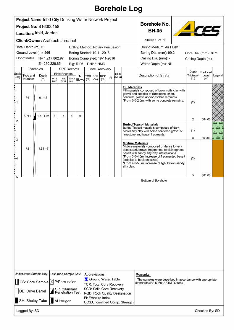
5
Total Depth (m): 5Ground Level (m): 566Coordinates:
3
2
0 - 1.5
(2)
(1)
(2)
8
561.00
Type andNumber
Iribd City Drinking Water Network Project
N= 1,217,862.97
5
Checked By: SD
94
1.95 - 5
1.5 - 1.95
Depth(m)
563.00
Bottom of Borehole
*From 4.0-5.0m; increase of light brown sandysilty clay.
*From 3.0-4.0m; increase of fragmented basalt(cobbles to boulders sizes)
Mixture MaterialsMixture materials composed of dense to verydense,dark brown, fragmented to disintegratedbasalt with sandy silty clay intercalations.
Buried Topsoil MaterialsBuried Topsoil materials composed of darkbrown silty clay with some scattered gravel oflimestone and basalt fragments.
Fill MaterialsFill materials composed of brown silty clay withgravel and cobbles of (limestone, chert,concrete, plastic and/or asphalt remains).
P2
SPT1
P1
564.00
*From 0.0-2.0m; with some concrete remains.
(Thickness)(m)
LegendUCS(MPa)RQD
(%)
Samples
TCR(%)
Borehole Log
15-30(cm)
P:Percussion
SH: Shelby Tube
E= 230,228.85SPT Records
Logged By: SD
Sheet 1 of 1
Borehole No.BH-05
Client/Owner:
Irbid, JordanProject No:Location:
S16000158Project Name:
* The samples were described in accordance with appropriatestandards (BS 5930; ASTM D2488).
Core Recovery
SCR(%)
NBlows30-45
(cm)
Abbreviations:
SPT:StandardPenetration Test
TCR: Total Core RecoverySCR: Solid Core RecoveryRQD: Rock Quality DesignationFI: Fracture IndexUCS:Unconfined Comp. Strength
Scale(m)
Undisturbed Sample Key:
DB: Drive Barrel
Remarks:
FI
Depth
Drilling Method: Rotary PercussionBoring Started: 19-11-2016Boring Completed: 19-11-2016Rig: R-06 Driller: HMD
1
2
3
4
5
0-15(cm)
Disturbed Sample Key:
ReducedLevel(m)
Description of Strata
Arabtech JerdanahDrilling Medium: Air FlushBoring Dia. (mm): 99.2Casing Dia. (mm): -Water Depth (m): Nil
Core Dia. (mm): 76.2Casing Depth (m): -
Ground Water Table
AU:Auger
CS: Core Sample
Field Records
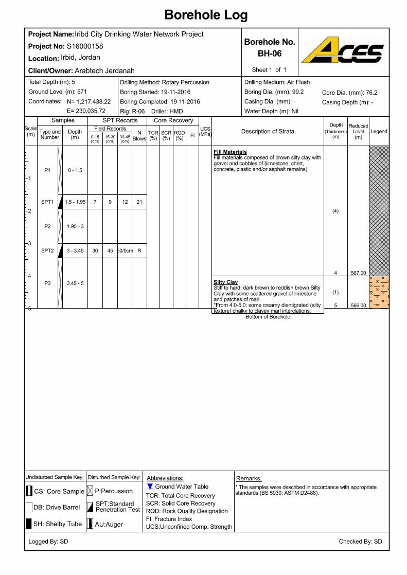
45
9
(1)
(4)
7
566.00
567.00
Bottom of Borehole
*From 4.0-5.0; some creamy dientigrated (siltytexture) chalky to clayey marl interclations.
Silty ClayStiff to hard, dark brown to reddish brown SiltyClay with some scattered gravel of limestoneand patches of marl.
Fill MaterialsFill materials composed of brown silty clay withgravel and cobbles of (limestone, chert,concrete, plastic and/or asphalt remains).
SH: Shelby Tube
30
N= 1,217,438.22
Depth(m)
Checked By: SD
Iribd City Drinking Water Network Project
R
12
3.45 - 5
3 - 3.45
1.95 - 3
1.5 - 1.95
0 - 1.5
5
4
50/0cm
P3
SPT2
P2
SPT1
P1
TCR: Total Core RecoverySCR: Solid Core RecoveryRQD: Rock Quality DesignationFI: Fracture IndexUCS:Unconfined Comp. Strength
SPT:StandardPenetration Test
SPT RecordsSamples
Logged By: SD
P:Percussion
DB: Drive Barrel
Project Name:
21
S16000158
Location:Project No:
Irbid, Jordan
SCR(%)
* The samples were described in accordance with appropriatestandards (BS 5930; ASTM D2488).
LegendNBlows30-45
(cm)
Abbreviations:
Borehole Log
Core RecoveryUCS(MPa)RQD
(%)TCR(%)15-30
(cm)
(Thickness)(m)
Ground Water TableUndisturbed Sample Key: Disturbed Sample Key: Remarks:
Field Records
Sheet 1 of 1
AU:Auger
Core Dia. (mm): 76.2Casing Depth (m): -
Drilling Medium: Air FlushBoring Dia. (mm): 99.2Casing Dia. (mm): -Water Depth (m): NilE= 230,035.72
Total Depth (m): 5Ground Level (m): 571Coordinates:
Type andNumber
CS: Core Sample
Scale(m) 0-15
(cm)
ReducedLevel(m)
Description of Strata
Arabtech Jerdanah
FI
Depth
Drilling Method: Rotary PercussionBoring Started: 19-11-2016Boring Completed: 19-11-2016Rig: R-06 Driller: HMD
Client/Owner:
Borehole No.BH-06
1
2
3
4
5
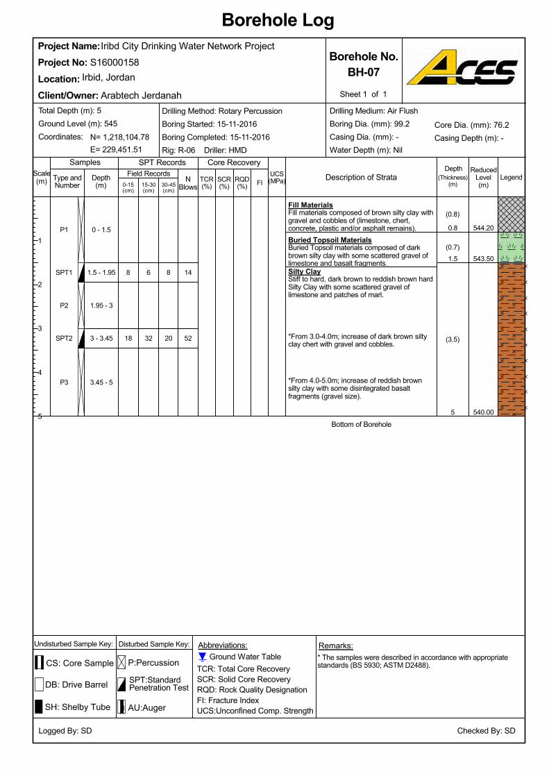
P3
SPT2
P2
SPT1
P1
32
0 - 1.5
52
14
20
8
Iribd City Drinking Water Network Project
3.45 - 5
1.5 - 1.95
5
1.5
0.8
1.95 - 3
(0.8)
18
8
540.00
543.50
544.20
(3.5)
Bottom of Borehole
*From 4.0-5.0m; increase of reddish brownsilty clay with some disintegrated basaltfragments (gravel size).
*From 3.0-4.0m; increase of dark brown siltyclay chert with gravel and cobbles.
Silty ClayStiff to hard, dark brown to reddish brown hardSilty Clay with some scattered gravel oflimestone and patches of marl.
Buried Topsoil MaterialsBuried Topsoil materials composed of darkbrown silty clay with some scattered gravel oflimestone and basalt fragments.
Fill MaterialsFill materials composed of brown silty clay withgravel and cobbles of (limestone, chert,concrete, plastic and/or asphalt remains).
(0.7)
6
LegendUCS(MPa)RQD
(%)TCR(%)15-30
(cm)
P:Percussion
SPT:StandardPenetration Test
SPT Records
3 - 3.45
DB: Drive Barrel
Sheet 1 of 1
Borehole No.BH-07
Client/Owner:
Irbid, JordanProject No:Location:
S16000158Project Name:
TCR: Total Core RecoverySCR: Solid Core RecoveryRQD: Rock Quality DesignationFI: Fracture IndexUCS:Unconfined Comp. Strength
Logged By: SD
(Thickness)(m)
SCR(%)
NBlows30-45
(cm)
Abbreviations:
Borehole Log
Core Recovery
* The samples were described in accordance with appropriatestandards (BS 5930; ASTM D2488).
Core Dia. (mm): 76.2Casing Depth (m): -
Undisturbed Sample Key:
Depth(m)
SH: Shelby Tube
N= 1,218,104.78
Remarks:
Checked By: SD
Samples
CS: Core Sample
Disturbed Sample Key:
Ground Water Table
Drilling Medium: Air FlushBoring Dia. (mm): 99.2Casing Dia. (mm): -Water Depth (m): NilE= 229,451.51
Total Depth (m): 5Ground Level (m): 545Coordinates:
Type andNumber
AU:Auger
0-15(cm)
ReducedLevel(m)
Description of Strata
Arabtech Jerdanah
1
2
3
4
5
Field RecordsFI
Depth
Drilling Method: Rotary PercussionBoring Started: 15-11-2016Boring Completed: 15-11-2016Rig: R-06 Driller: HMD
Scale(m)
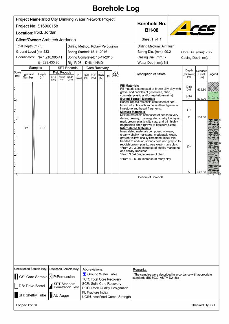
0.5
Remarks:
0 - 5
5
1
Checked By: SD
2
Field Records
CS: Core Sample
AU:Auger
Iribd City Drinking Water Network Project
Core Dia. (mm): 76.2Casing Depth (m): -
E= 229,430.96
Type andNumber
(3)
SH: Shelby Tube
N= 1,218,985.41
Depth(m)
Total Depth (m): 5Ground Level (m): 533Coordinates:
Buried Topsoil MaterialsBuried Topsoil materials composed of darkbrown silty clay with some scattered gravel oflimestone and basalt fragments.
Fill MaterialsFill materials composed of brown silty clay withgravel and cobbles of (limestone, chert,concrete, plastic and/or asphalt remains).
P1
*From 2.0-3.0m; increase of chalky marlstoneand chalky limestone.
532.50
Ground Water Table
(1)
(0.5)
(0.5)
528.00
Mixture Materials Mixture materials composed of dense to verydense, creamy, disintegrated chalky to clayeymarl; brown, plastic silty clay; and thin highlyfragmented chert (gravel to boulders sizes).
532.00
Intercalated MaterialsIntercalated materials composed of weak,creamy chalky marlstone; moderately weak,grayish yellow, chalky limestone; black thinbedded to nodular, strong chert; and grayish toreddish brown, plastic, very weak marly clay.
Bottom of Borehole
*From 4.0-5.0m; increase of marly clay.*From 3.0-4.0m; increase of chert.
531.00
Disturbed Sample Key:
(Thickness)(m)
LegendUCS(MPa)
Borehole Log
RQD(%)
Abbreviations:
TCR(%)15-30
(cm)
P:Percussion
Drilling Medium: Air FlushBoring Dia. (mm): 99.2Casing Dia. (mm): -Water Depth (m): Nil
* The samples were described in accordance with appropriatestandards (BS 5930; ASTM D2488).
Sheet 1 of 1
Borehole No.BH-08
Client/Owner:
Irbid, JordanProject No:Location:
S16000158
Core Recovery
TCR: Total Core RecoverySCR: Solid Core RecoveryRQD: Rock Quality DesignationFI: Fracture IndexUCS:Unconfined Comp. Strength
Logged By: SD
SCR(%)
NBlows30-45
(cm)
Project Name:
Depth
Arabtech Jerdanah
1
2
3
4
5
Scale(m)
SPT:StandardPenetration Test
Description of Strata
Drilling Method: Rotary PercussionBoring Started: 15-11-2016Boring Completed: 15-11-2016Rig: R-06 Driller: HMD
Undisturbed Sample Key:
FI
Samples
DB: Drive Barrel
SPT Records
0-15(cm)
ReducedLevel(m)
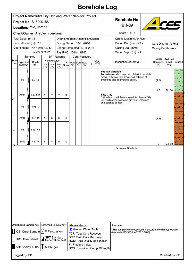
Topsoil MaterialsTopsoil materials composed of dark to reddishbrown, silty clay with gravel and cobbles oflimestone and fragmented basalt.
SPT2
8
5
7
508.00
511.50
(3.5)
Silty ClayStiff to hard, dark brown to reddish brown SiltyClay with some scattered gravel of limestoneand patches of marl.
SPT3
14
Bottom of Borehole5
11
6
7
4.5 - 5
Iribd City Drinking Water Network Project
3 - 3.45
1.5 - 1.95
(1.5)
P2
1.5
8
6
7
0 - 1.5
P3
SPT1
P1
3.45 - 4.5
NBlows
Samples
DB: Drive Barrel
0-15(cm)
SPT:StandardPenetration Test
ReducedLevel(m)
1.95 - 3
SCR(%)
12
Arabtech Jerdanah
Logged By: SD
* The samples were described in accordance with appropriatestandards (BS 5930; ASTM D2488).
30-45(cm)
Abbreviations:
Borehole Log
Core Recovery
(Thickness)(m)
Legend
SPT RecordsUCS(MPa)
Project Name:
RQD(%)
TCR(%)15-30
(cm)
P:PercussionGround Water Table
Core Dia. (mm): 76.2Casing Depth (m): -
Drilling Medium: Air FlushBoring Dia. (mm): 99.2Casing Dia. (mm): -Water Depth (m): Nil
Client/Owner:
Borehole No.BH-09
E= 229,389.72
Sheet 1 of 1
Total Depth (m): 5Ground Level (m): 513Coordinates:
Type andNumber
TCR: Total Core RecoverySCR: Solid Core RecoveryRQD: Rock Quality DesignationFI: Fracture IndexUCS:Unconfined Comp. Strength
Field Records
SH: Shelby Tube
N= 1,219,342.53
Depth(m)
Checked By: SD
19
DepthDescription of Strata
S16000158
1
2
3
4
5
Location:Project No:
Irbid, Jordan
Scale(m)
AU:Auger
CS: Core Sample
Drilling Method: Rotary PercussionBoring Started: 13-11-2016Boring Completed: 13-11-2016Rig: R-06 Driller: HMD
Undisturbed Sample Key: Disturbed Sample Key: Remarks:
FI
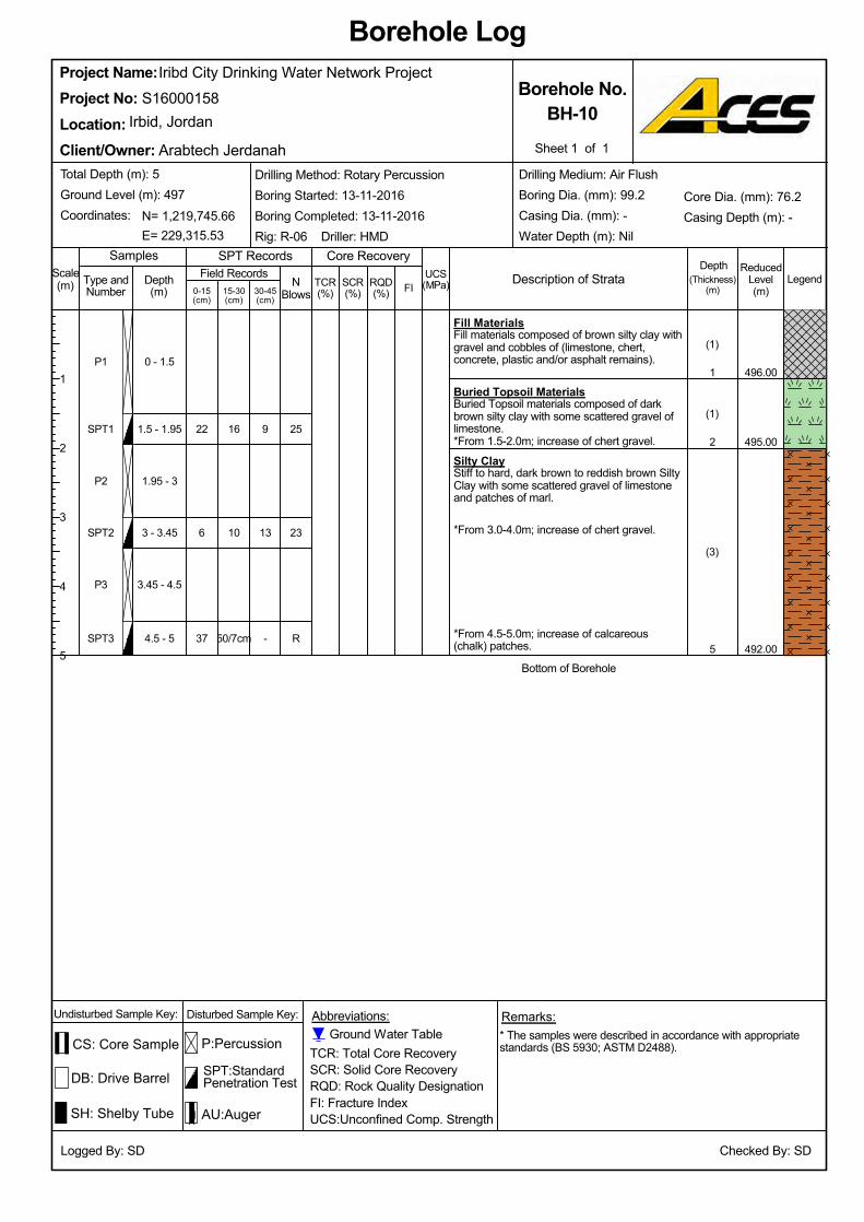
495.00
496.00
Bottom of Borehole
*From 4.5-5.0m; increase of calcareous(chalk) patches.
Iribd City Drinking Water Network Project
Silty ClayStiff to hard, dark brown to reddish brown SiltyClay with some scattered gravel of limestoneand patches of marl.
Buried Topsoil MaterialsBuried Topsoil materials composed of darkbrown silty clay with some scattered gravel oflimestone.
Fill MaterialsFill materials composed of brown silty clay withgravel and cobbles of (limestone, chert,concrete, plastic and/or asphalt remains).
SPT3
P3
SPT2
P2
SPT1
P1
Depth(m)
Checked By: SD
R
23
25
-
SH: Shelby Tube
9
4.5 - 5
3.45 - 4.5
3 - 3.45
1.95 - 3
1.5 - 1.95
0 - 1.5
5
2
1
13 *From 3.0-4.0m; increase of chert gravel.
N= 1,219,745.66
Type andNumber
DB: Drive Barrel
492.00
TCR(%)15-30
(cm)
P:Percussion
SPT:StandardPenetration Test
SamplesUCS(MPa)0-15
(cm)
ReducedLevel(m)
Description of Strata
*From 1.5-2.0m; increase of chert gravel.
SPT Records
SCR(%)
Sheet 1 of 1
Borehole No.BH-10
Client/Owner:
Irbid, JordanProject No:Location:
S16000158Project Name:
TCR: Total Core RecoverySCR: Solid Core RecoveryRQD: Rock Quality DesignationFI: Fracture IndexUCS:Unconfined Comp. Strength
* The samples were described in accordance with appropriatestandards (BS 5930; ASTM D2488).
Logged By: SD
RQD(%)
NBlows30-45
(cm)
Abbreviations:
Borehole Log
Core Recovery
(Thickness)(m)
Legend
6
E= 229,315.53
16
1
2
3
4
5
Arabtech JerdanahDrilling Medium: Air FlushBoring Dia. (mm): 99.2Casing Dia. (mm): -Water Depth (m): Nil
37
(1)
50/7cm
(1)
(3)
10
22
Scale(m) FI
Depth
Drilling Method: Rotary PercussionBoring Started: 13-11-2016Boring Completed: 13-11-2016Rig: R-06 Driller: HMD
Total Depth (m): 5Ground Level (m): 497Coordinates:
Core Dia. (mm): 76.2Casing Depth (m): -
Undisturbed Sample Key: Disturbed Sample Key: Remarks:
Field Records
CS: Core Sample
AU:Auger
Ground Water Table
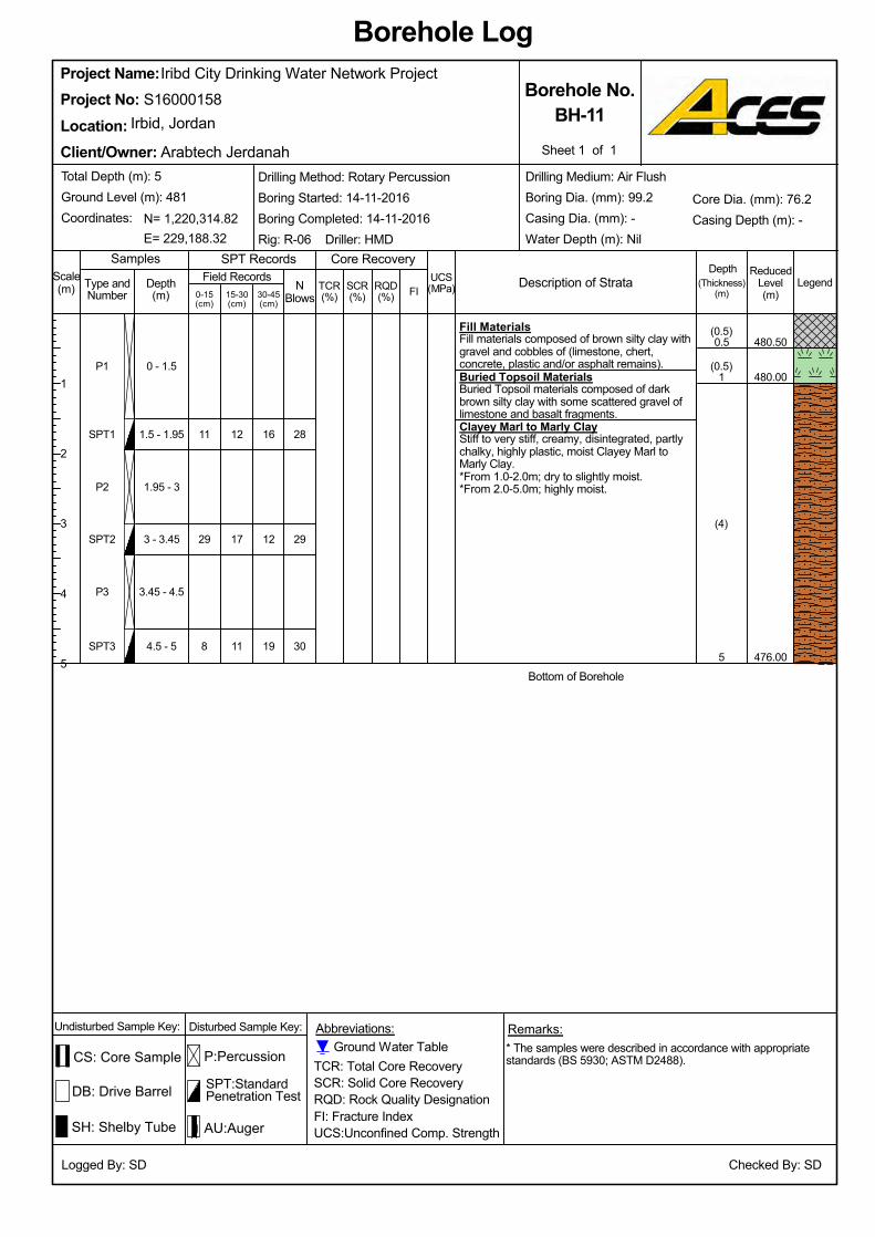
Clayey Marl to Marly ClayStiff to very stiff, creamy, disintegrated, partlychalky, highly plastic, moist Clayey Marl toMarly Clay.
11
476.00
480.00
480.50
Bottom of Borehole
8
*From 1.0-2.0m; dry to slightly moist.
Buried Topsoil MaterialsBuried Topsoil materials composed of darkbrown silty clay with some scattered gravel oflimestone and basalt fragments.
Fill MaterialsFill materials composed of brown silty clay withgravel and cobbles of (limestone, chert,concrete, plastic and/or asphalt remains).
SPT3
*From 2.0-5.0m; highly moist.
4.5 - 5
3.45 - 4.5
3 - 3.45
1.95 - 3
1.5 - 1.95
0 - 1.5
Iribd City Drinking Water Network Project
1
29
P2
11
17
12
(4)
(0.5)
(0.5)
P3
5
SPT1
P1
SPT2
NBlows0-15
(cm)
ReducedLevel(m)
Description of Strata
TCR: Total Core RecoverySCR: Solid Core RecoveryRQD: Rock Quality DesignationFI: Fracture IndexUCS:Unconfined Comp. Strength
Samples
0.5
16
SCR(%)
1
2
3
4
5
Logged By: SD
30-45(cm)
Arabtech Jerdanah
TCR(%)
Abbreviations:
Borehole Log
Core Recovery
(Thickness)(m)
LegendUCS(MPa)
DB: Drive Barrel
15-30(cm)
P:Percussion
SPT:StandardPenetration Test
SPT RecordsScale(m) RQD
(%)
Project No:Irbid, Jordan
SH: Shelby Tube
Client/Owner:
Borehole No.BH-11
* The samples were described in accordance with appropriatestandards (BS 5930; ASTM D2488).
Sheet 1 of 1
E= 229,188.32
Depth(m)
Checked By: SD
30
29
28
19
12
N= 1,220,314.82
Project Name:S16000158
Location:
FI
Depth
Drilling Method: Rotary PercussionBoring Started: 14-11-2016Boring Completed: 14-11-2016Rig: R-06 Driller: HMD
Type andNumber
Total Depth (m): 5Ground Level (m): 481Coordinates:
Undisturbed Sample Key: Disturbed Sample Key: Remarks:
Field Records
CS: Core Sample
AU:Auger
Ground Water Table
Core Dia. (mm): 76.2Casing Depth (m): -
Drilling Medium: Air FlushBoring Dia. (mm): 99.2Casing Dia. (mm): -Water Depth (m): Nil
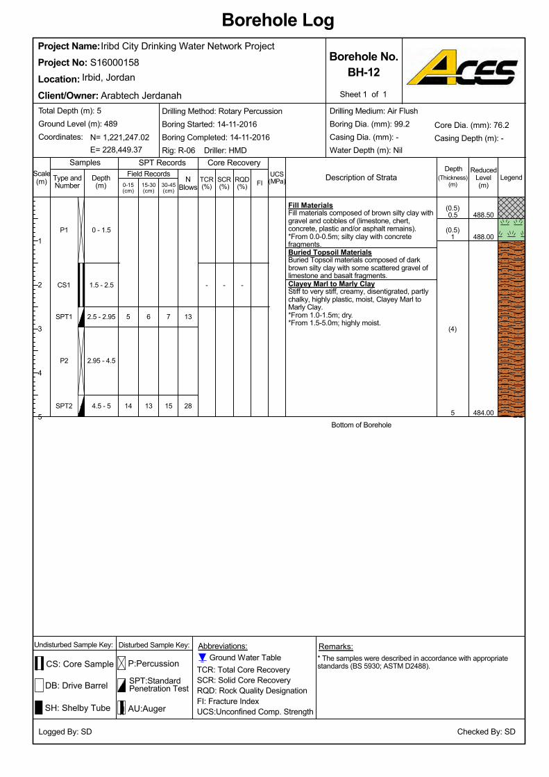
*From 1.0-1.5m; dry.
14
5
484.00
488.00
488.50
*From 1.5-5.0m; highly moist.(4)
Clayey Marl to Marly ClayStiff to very stiff, creamy, disentigrated, partlychalky, highly plastic, moist, Clayey Marl toMarly Clay.
Buried Topsoil MaterialsBuried Topsoil materials composed of darkbrown silty clay with some scattered gravel oflimestone and basalt fragments.
*From 0.0-0.5m; silty clay with concretefragments.
Fill MaterialsFill materials composed of brown silty clay withgravel and cobbles of (limestone, chert,concrete, plastic and/or asphalt remains).
15
Bottom of Borehole
7
4.5 - 5
2.95 - 4.5
2.5 - 2.95
1.5 - 2.5
Iribd City Drinking Water Network Project
1
(0.5)
(0.5)
--
13
6
SPT2
0.5
P2
SPT1
CS1
P1 0 - 1.5
ReducedLevel(m)
Samples
DB: Drive Barrel
0-15(cm)
NBlows
SCR(%)
5
Logged By: SD
Description of Strata
* The samples were described in accordance with appropriatestandards (BS 5930; ASTM D2488).TCR: Total Core Recovery
SCR: Solid Core RecoveryRQD: Rock Quality DesignationFI: Fracture IndexUCS:Unconfined Comp. Strength
Arabtech Jerdanah
Project Name:
30-45(cm)
Abbreviations:
Borehole Log
Core Recovery
(Thickness)(m)
Legend
SPT RecordsUCS(MPa)
SPT:StandardPenetration Test
RQD(%)
TCR(%)15-30
(cm)
P:Percussion
S16000158
Total Depth (m): 5Ground Level (m): 489Coordinates:
Type andNumber
Project No:Irbid, Jordan
Client/Owner:
Borehole No.BH-12
Drilling Medium: Air FlushBoring Dia. (mm): 99.2Casing Dia. (mm): -Water Depth (m): Nil
Core Dia. (mm): 76.2Casing Depth (m): -
SH: Shelby Tube
N= 1,221,247.02
Depth(m)
Checked By: SD
-
28
13
Sheet 1 of 1
1
2
3
4
5
Scale(m) FI
Depth
E= 228,449.37
Location:
Undisturbed Sample Key: Disturbed Sample Key: Remarks:
Field Records
CS: Core Sample
AU:Auger
Ground Water Table
Drilling Method: Rotary PercussionBoring Started: 14-11-2016Boring Completed: 14-11-2016Rig: R-06 Driller: HMD
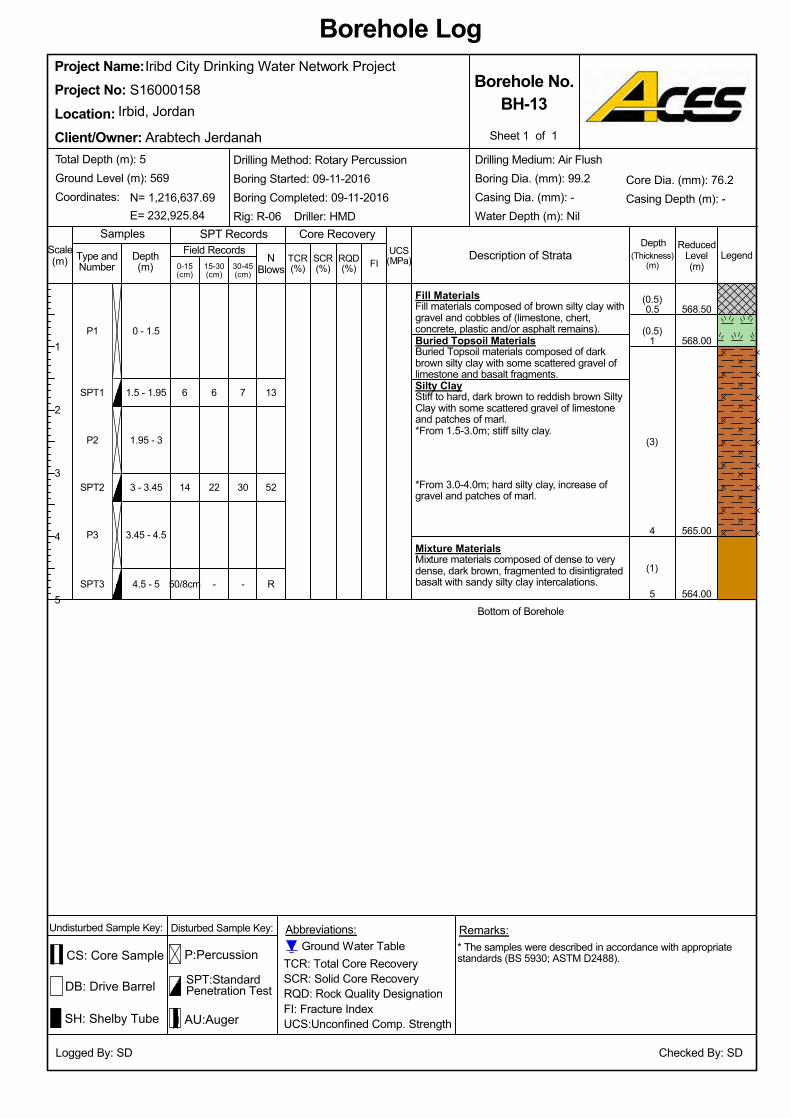
(3)
(0.5)
(0.5)
50/8cm
14
6
564.00
565.00
568.50
6
Bottom of Borehole
Mixture MaterialsMixture materials composed of dense to verydense, dark brown, fragmented to disintigratedbasalt with sandy silty clay intercalations.
*From 3.0-4.0m; hard silty clay, increase ofgravel and patches of marl.
*From 1.5-3.0m; stiff silty clay.
Silty ClayStiff to hard, dark brown to reddish brown SiltyClay with some scattered gravel of limestoneand patches of marl.
Buried Topsoil MaterialsBuried Topsoil materials composed of darkbrown silty clay with some scattered gravel oflimestone and basalt fragments.
Fill MaterialsFill materials composed of brown silty clay withgravel and cobbles of (limestone, chert,concrete, plastic and/or asphalt remains).
568.00
1.5 - 1.95
0 - 1.5
5
4
1
0.5
Iribd City Drinking Water Network Project
(1)-
22
3.45 - 4.5
SPT3
P3
SPT2
P2
SPT1
P1
SPT:StandardPenetration Test
UCS(MPa)RQD
(%)TCR(%)15-30
(cm)
P:Percussion
ReducedLevel(m)
SPT RecordsSamples
DB: Drive Barrel
0-15(cm)
1.95 - 3
Sheet 1 of 1
Borehole No.BH-13
Client/Owner:
Irbid, JordanProject No:Location:
S16000158Project Name:
TCR: Total Core RecoverySCR: Solid Core RecoveryRQD: Rock Quality DesignationFI: Fracture IndexUCS:Unconfined Comp. Strength
* The samples were described in accordance with appropriatestandards (BS 5930; ASTM D2488).
LegendSCR(%)
NBlows30-45
(cm)
Abbreviations:
Borehole Log
Core Recovery
(Thickness)(m)
Logged By: SD
E= 232,925.84
Total Depth (m): 5Ground Level (m): 569Coordinates:
Type andNumber
SH: Shelby Tube
N= 1,216,637.69
Depth(m)
Ground Water Table
R
52
13
-
30
7
4.5 - 5
Checked By: SD
Description of Strata
Arabtech Jerdanah
1
2
3
4
5
Scale(m) FI
Drilling Medium: Air FlushBoring Dia. (mm): 99.2Casing Dia. (mm): -Water Depth (m): Nil
Drilling Method: Rotary PercussionBoring Started: 09-11-2016Boring Completed: 09-11-2016Rig: R-06 Driller: HMD
Core Dia. (mm): 76.2Casing Depth (m): -
Undisturbed Sample Key: Disturbed Sample Key: Remarks:
Field Records
CS: Core Sample
AU:Auger
3 - 3.45
Depth
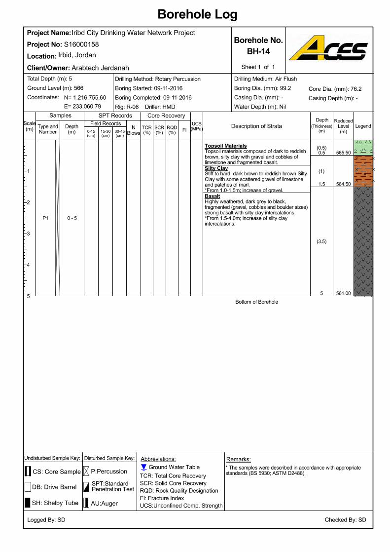
N= 1,216,755.60
Depth(m)
Checked By: SD
0 - 5
5
1.5
0.5
Core Dia. (mm): 76.2Casing Depth (m): -
Undisturbed Sample Key:
Iribd City Drinking Water Network Project
Remarks:
CS: Core Sample
SH: Shelby Tube
Ground Water Table
Drilling Medium: Air FlushBoring Dia. (mm): 99.2Casing Dia. (mm): -Water Depth (m): NilE= 233,060.79
Total Depth (m): 5Ground Level (m): 566Coordinates:
Type andNumber
AU:Auger
Silty ClayStiff to hard, dark brown to reddish brown SiltyClay with some scattered gravel of limestoneand patches of marl.
Topsoil MaterialsTopsoil materials composed of dark to reddishbrown, silty clay with gravel and cobbles oflimestone and fragmented basalt.
BasaltHighly weathered, dark grey to black,fragmented (gravel, cobbles and boulder sizes)strong basalt with silty clay intercalations.*From 1.5-4.0m; increase of silty clayintercalations.
P1
(3.5)
(1)
*From 1.0-1.5m; increase of gravel.
Disturbed Sample Key:
561.00
564.50
565.50
Bottom of Borehole
(0.5)
TCR(%)
Project Name:
LegendUCS(MPa)15-30
(cm)
Field Records
Irbid, Jordan
Client/Owner:
RQD(%)
SCR(%)
TCR: Total Core RecoverySCR: Solid Core RecoveryRQD: Rock Quality DesignationFI: Fracture IndexUCS:Unconfined Comp. Strength
* The samples were described in accordance with appropriatestandards (BS 5930; ASTM D2488).
Logged By: SD
S16000158
Location:
(Thickness)(m)
Sheet 1 of 1
NBlows30-45
(cm)
Abbreviations:
Borehole Log
Core Recovery
Project No:
Description of Strata
Arabtech Jerdanah
1
2
3
4
5
Borehole No.BH-14
FI
Depth
Drilling Method: Rotary PercussionBoring Started: 09-11-2016Boring Completed: 09-11-2016Rig: R-06 Driller: HMD
Scale(m)
SPT:StandardPenetration Test
SPT Records
DB: Drive Barrel
ReducedLevel(m)0-15
(cm)
P:Percussion
Samples

Buried Topsoil MaterialsBuried Topsoil materials composed of darkbrown silty clay with some scattered gravel oflimestone and basalt fragments.13
603.00
606.50
607.00
Bottom of Borehole
8
Silty ClayStiff to hard, dark brown to reddish brown SiltyClay with some scattered gravel of limestoneand patches of marl.
*From 0.0-1.0m; increase of limestone gravel.
Fill MaterialsFill materials composed of brown silty clay withgravel and cobbles of (limestone, chert,concrete, plastic and/or asphalt remains).
SPT3
*From 1.5-5.0m; dark brown colored silty clay.
4.5 - 5
3.45 - 4.5
3 - 3.45
1.95 - 3
1.5 - 1.95
0 - 1.5
Iribd City Drinking Water Network Project
1.5
8
P2
9
7
10
(3.5)
(0.5)
(1)
P3
5
SPT1
P1
SPT2
NBlows0-15
(cm)
ReducedLevel(m)
Description of Strata
TCR: Total Core RecoverySCR: Solid Core RecoveryRQD: Rock Quality DesignationFI: Fracture IndexUCS:Unconfined Comp. Strength
Samples
1
8
SCR(%)
1
2
3
4
5
Logged By: SD
30-45(cm)
Arabtech Jerdanah
TCR(%)
Abbreviations:
Borehole Log
Core Recovery
(Thickness)(m)
LegendUCS(MPa)
DB: Drive Barrel
15-30(cm)
P:Percussion
SPT:StandardPenetration Test
SPT RecordsScale(m) RQD
(%)
Project No:Irbid, Jordan
SH: Shelby Tube
Client/Owner:
Borehole No.BH-15
* The samples were described in accordance with appropriatestandards (BS 5930; ASTM D2488).
Sheet 1 of 1
E= 232,181.00
Depth(m)
Checked By: SD
18
15
18
9
8
N= 1,213,663.00
Project Name:S16000158
Location:
FI
Depth
Drilling Method: Rotary PercussionBoring Started: 16-11-2016Boring Completed: 16-11-2016Rig: R-06 Driller: HMD
Type andNumber
Total Depth (m): 5Ground Level (m): 608Coordinates:
Undisturbed Sample Key: Disturbed Sample Key: Remarks:
Field Records
CS: Core Sample
AU:Auger
Ground Water Table
Core Dia. (mm): 76.2Casing Depth (m): -
Drilling Medium: Air FlushBoring Dia. (mm): 99.2Casing Dia. (mm): -Water Depth (m): Nil
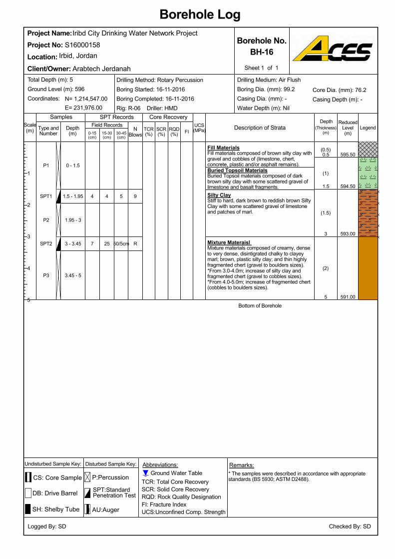
P1
SPT1
591.00
Buried Topsoil MaterialsBuried Topsoil materials composed of darkbrown silty clay with some scattered gravel oflimestone and basalt fragments.
593.00
594.50
595.50
Iribd City Drinking Water Network Project
1.95 - 3
Bottom of Borehole
*From 4.0-5.0m; increase of fragmented chert(cobbles to boulders sizes).
*From 3.0-4.0m; increase of silty clay andfragmented chert (gravel to cobbles sizes).
Silty ClayStiff to hard, dark brown to reddish brown SiltyClay with some scattered gravel of limestoneand patches of marl.
Fill MaterialsFill materials composed of brown silty clay withgravel and cobbles of (limestone, chert,concrete, plastic and/or asphalt remains).
P3
SPT2
P2
Mixture Materaisl Mixture materials composed of creamy, denseto very dense, disintigrated chalky to clayeymarl; brown, plastic silty clay; and thin highlyfragmented chert (gravel to boulders sizes).
Checked By: SD
E= 231,976.00
Total Depth (m): 5Ground Level (m): 596Coordinates:
Type andNumber
SH: Shelby Tube
Core Dia. (mm): 76.2Casing Depth (m): -
Depth(m)
Ground Water Table
R
9
50/5cm
5
3.45 - 5
3 - 3.45
N= 1,214,547.00
Drilling Medium: Air FlushBoring Dia. (mm): 99.2Casing Dia. (mm): -Water Depth (m): Nil
Undisturbed Sample Key: Disturbed Sample Key: Remarks:
Field Records
CS: Core Sample
AU:Auger
Samples
Arabtech Jerdanah
RQD(%)
TCR(%)15-30
(cm)
P:Percussion
UCS(MPa)
SPT Records
DB: Drive Barrel
0-15(cm)
ReducedLevel(m)
SPT:StandardPenetration Test
SCR(%)
Sheet 1 of 1
Borehole No.BH-16
Client/Owner:
Irbid, JordanProject No:Location:
S16000158Project Name:
TCR: Total Core RecoverySCR: Solid Core RecoveryRQD: Rock Quality DesignationFI: Fracture IndexUCS:Unconfined Comp. Strength
* The samples were described in accordance with appropriatestandards (BS 5930; ASTM D2488).
Logged By: SD
NBlows30-45
(cm)
Abbreviations:
Borehole Log
Core Recovery
(Thickness)(m)
Legend
(0.5)
(1)
(1.5)
4
Description of Strata
0.5
4
25
(2)
1
2
3
4
5
Scale(m) FI
7
Drilling Method: Rotary PercussionBoring Started: 16-11-2016Boring Completed: 16-11-2016Rig: R-06 Driller: HMD
1.5 - 1.95
0 - 1.5
5
3
1.5
Depth
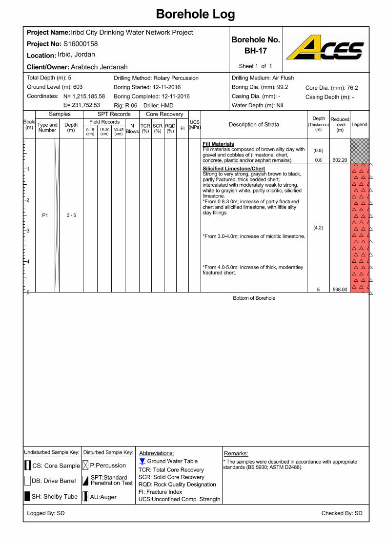
Checked By: SD
SH: Shelby Tube
Type andNumber
Depth(m)
Total Depth (m): 5Ground Level (m): 603Coordinates:
0 - 5
N= 1,215,185.58
Field Records
Iribd City Drinking Water Network Project
Undisturbed Sample Key: Remarks:
0.8
CS: Core Sample
AU:Auger
Ground Water Table
Core Dia. (mm): 76.2Casing Depth (m): -
Drilling Medium: Air FlushBoring Dia. (mm): 99.2Casing Dia. (mm): -Water Depth (m): NilE= 231,752.53
Disturbed Sample Key:
*From 3.0-4.0m; increase of micritic limestone.
*From 0.8-3.0m; increase of partly fracturedchert and silicified limestone, with little siltyclay fillings.
Silicified Limestone/ChertStrong to very strong, grayish brown to black,partly fractured, thick bedded chert;intercalated with moderately weak to strong,white to grayish white, partly micritic, silicifiedlimestone.
Fill MaterialsFill materials composed of brown silty clay withgravel and cobbles of (limestone, chert,concrete, plastic and/or asphalt remains).
P1
(4.2)
*From 4.0-5.0m; increase of thick, moderatleyfractured chert.
Bottom of Borehole
(0.8)
598.00
602.20
5
Location:
(Thickness)(m)
Legend
Borehole Log
UCS(MPa)
Abbreviations:
RQD(%)
Borehole No.BH-17
Sheet 1 of 1
Drilling Method: Rotary PercussionBoring Started: 12-11-2016Boring Completed: 12-11-2016Rig: R-06 Driller: HMD
S16000158Project Name:
TCR: Total Core RecoverySCR: Solid Core RecoveryRQD: Rock Quality DesignationFI: Fracture IndexUCS:Unconfined Comp. Strength
* The samples were described in accordance with appropriatestandards (BS 5930; ASTM D2488).
Project No:Irbid, Jordan
Core Recovery
Logged By: SD
15-30(cm)
SCR(%)
NBlows30-45
(cm)
Client/Owner:
ReducedLevel(m)
Description of Strata
Arabtech Jerdanah
TCR(%)
1
2
3
4
5
Scale(m) FI
DepthSPT Records
P:Percussion
0-15(cm)
SPT:StandardPenetration Test
Samples
DB: Drive Barrel
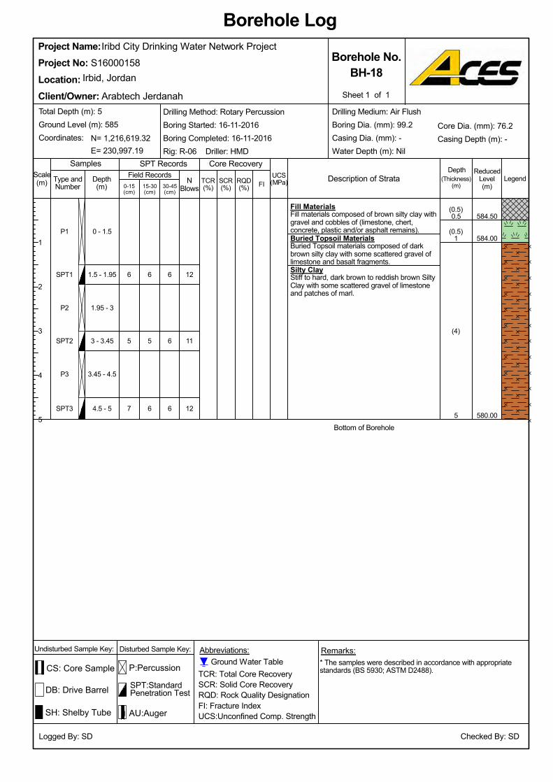
SPT2
P2
SPT1
P1
SPT3
6
4.5 - 5
3.45 - 4.5
3 - 3.45
1.95 - 3
1.5 - 1.95
0 - 1.5
Iribd City Drinking Water Network Project
5
P3
6
5
6
(4)
(0.5)
0.5(0.5)
7
5
6
580.00
584.00
Bottom of Borehole
Silty ClayStiff to hard, dark brown to reddish brown SiltyClay with some scattered gravel of limestoneand patches of marl.
Buried Topsoil MaterialsBuried Topsoil materials composed of darkbrown silty clay with some scattered gravel oflimestone and basalt fragments.
Fill MaterialsFill materials composed of brown silty clay withgravel and cobbles of (limestone, chert,concrete, plastic and/or asphalt remains).
584.50
SPT:StandardPenetration Test
UCS(MPa)RQD
(%)TCR(%)15-30
(cm)
P:Percussion
ReducedLevel(m)
SPT RecordsSamples
DB: Drive Barrel
1
6
0-15(cm)
Sheet 1 of 1
Borehole No.BH-18
Client/Owner:
Irbid, JordanProject No:Location:
S16000158Project Name:
TCR: Total Core RecoverySCR: Solid Core RecoveryRQD: Rock Quality DesignationFI: Fracture IndexUCS:Unconfined Comp. Strength
* The samples were described in accordance with appropriatestandards (BS 5930; ASTM D2488).
LegendSCR(%)
NBlows30-45
(cm)
Abbreviations:
Borehole Log
Core Recovery
(Thickness)(m)
Logged By: SD
N= 1,216,619.32Core Dia. (mm): 76.2Casing Depth (m): -
Drilling Medium: Air FlushBoring Dia. (mm): 99.2Casing Dia. (mm): -Water Depth (m): NilE= 230,997.19
Total Depth (m): 5Ground Level (m): 585Coordinates:
Type andNumber
Ground Water Table
SH: Shelby Tube
Depth(m)
Checked By: SD
12
11
12
6
Description of Strata
Arabtech Jerdanah
1
2
3
4
5
AU:Auger
FI
Depth
Drilling Method: Rotary PercussionBoring Started: 16-11-2016Boring Completed: 16-11-2016Rig: R-06 Driller: HMD
Undisturbed Sample Key:
Scale(m)
Disturbed Sample Key: Remarks:
Field Records
CS: Core Sample
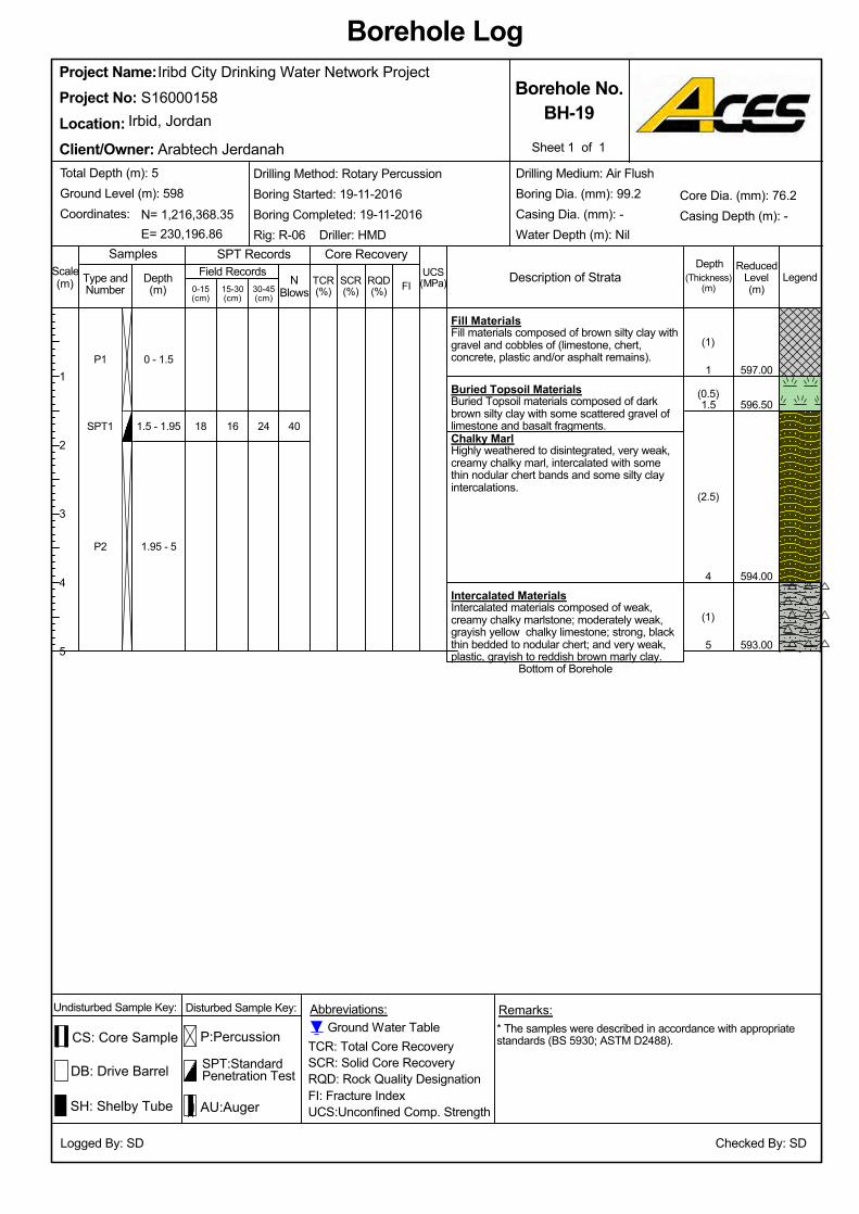
(1)
4
(2.5)
(0.5)
(1)
18
593.00
594.00
16 40
SH: Shelby Tube
N= 1,216,368.35
Iribd City Drinking Water Network Project
Checked By: SD
1
1.5
24
1.95 - 5
1.5 - 1.95
0 - 1.5
5
596.50
Depth(m)
Bottom of Borehole
Intercalated MaterialsIntercalated materials composed of weak,creamy chalky marlstone; moderately weak,grayish yellow chalky limestone; strong, blackthin bedded to nodular chert; and very weak,plastic, grayish to reddish brown marly clay.
Chalky MarlHighly weathered to disintegrated, very weak,creamy chalky marl, intercalated with somethin nodular chert bands and some silty clayintercalations.
Buried Topsoil MaterialsBuried Topsoil materials composed of darkbrown silty clay with some scattered gravel oflimestone and basalt fragments.
597.00
P2
SPT1
P1
Fill MaterialsFill materials composed of brown silty clay withgravel and cobbles of (limestone, chert,concrete, plastic and/or asphalt remains).
LegendUCS(MPa)RQD
(%)TCR(%)15-30
(cm)
P:Percussion
SPT:StandardPenetration Test
Samples
Logged By: SD
Sheet 1 of 1
Borehole No.BH-19
Client/Owner:
Irbid, JordanProject No:Location:
S16000158Project Name:
(Thickness)(m)
* The samples were described in accordance with appropriatestandards (BS 5930; ASTM D2488).
DB: Drive Barrel
SCR(%)
NBlows30-45
(cm)
Abbreviations:
Borehole Log
Core Recovery
TCR: Total Core RecoverySCR: Solid Core RecoveryRQD: Rock Quality DesignationFI: Fracture IndexUCS:Unconfined Comp. Strength
Field Records
Remarks:Disturbed Sample Key:
Scale(m)
Undisturbed Sample Key:
AU:Auger
FI
Depth
Drilling Method: Rotary PercussionBoring Started: 19-11-2016Boring Completed: 19-11-2016Rig: R-06 Driller: HMD
SPT Records
0-15(cm)
ReducedLevel(m)
CS: Core Sample
Arabtech Jerdanah
1
2
3
4
5
Type andNumber
Total Depth (m): 5Ground Level (m): 598Coordinates:
E= 230,196.86
Drilling Medium: Air FlushBoring Dia. (mm): 99.2Casing Dia. (mm): -Water Depth (m): Nil
Core Dia. (mm): 76.2Casing Depth (m): -
Ground Water Table
Description of Strata
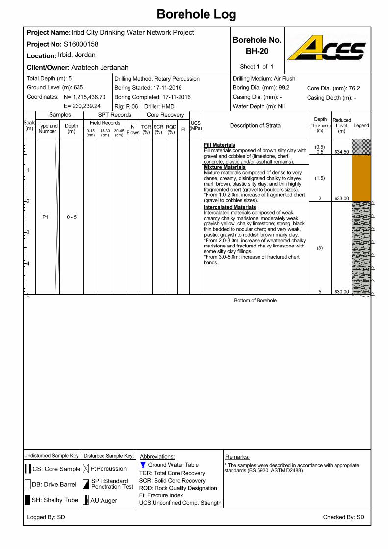
N= 1,215,436.70
Depth(m)
Checked By: SD
0 - 5
5
2
0.5
Core Dia. (mm): 76.2Casing Depth (m): -
Undisturbed Sample Key:
Iribd City Drinking Water Network Project
Remarks:
CS: Core Sample
SH: Shelby Tube
Ground Water Table
Drilling Medium: Air FlushBoring Dia. (mm): 99.2Casing Dia. (mm): -Water Depth (m): NilE= 230,239.24
Total Depth (m): 5Ground Level (m): 635Coordinates:
Type andNumber
AU:Auger
*From 1.0-2.0m; increase of fragmented chert(gravel to cobbles sizes).
Mixture MaterialsMixture materials composed of dense to verydense, creamy, disintigrated chalky to clayeymarl; brown, plastic silty clay; and thin highlyfragmented chert (gravel to boulders sizes).
Fill MaterialsFill materials composed of brown silty clay withgravel and cobbles of (limestone, chert,concrete, plastic and/or asphalt remains).
*From 3.0-5.0m; increase of fractured chertbands.
P1
630.00
Disturbed Sample Key:
(3)
(1.5)
(0.5)
Intercalated MaterialsIntercalated materials composed of weak,creamy chalky marlstone; moderately weak,grayish yellow chalky limestone; strong, blackthin bedded to nodular chert; and very weak,plastic, grayish to reddish brown marly clay.*From 2.0-3.0m; increase of weathered chalkymarlstone and fractured chalky limestone withsome silty clay fillings.
633.00
634.50
Bottom of Borehole
Borehole Log
Core Recovery
(Thickness)(m)
LegendUCS(MPa)RQD
(%)TCR(%)15-30
(cm)
Field Records
TCR: Total Core RecoverySCR: Solid Core RecoveryRQD: Rock Quality DesignationFI: Fracture IndexUCS:Unconfined Comp. Strength
Sheet 1 of 1
Borehole No.BH-20
Client/Owner:
Irbid, JordanProject No:Location:
Abbreviations:
Project Name:
30-45(cm)
* The samples were described in accordance with appropriatestandards (BS 5930; ASTM D2488).
Logged By: SD
SCR(%)
NBlows
S16000158
ReducedLevel(m)
Description of Strata
Arabtech Jerdanah
1
2
3
4
5
0-15(cm)
FI
Depth
Drilling Method: Rotary PercussionBoring Started: 17-11-2016Boring Completed: 17-11-2016Rig: R-06 Driller: HMD
Scale(m)
DB: Drive Barrel
P:Percussion
SPT:StandardPenetration Test
Samples SPT Records
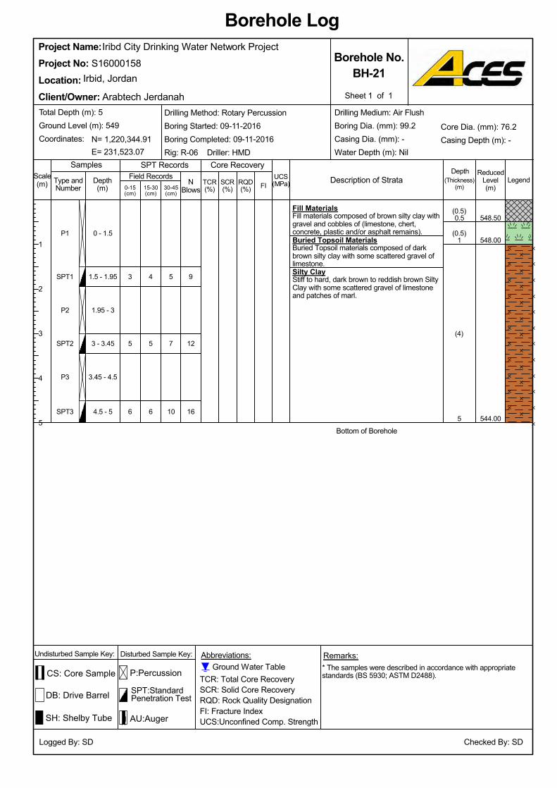
Buried Topsoil MaterialsBuried Topsoil materials composed of darkbrown silty clay with some scattered gravel oflimestone.
SPT2 5
3
544.00
548.00
548.50
Silty ClayStiff to hard, dark brown to reddish brown SiltyClay with some scattered gravel of limestoneand patches of marl.
(0.5)Fill MaterialsFill materials composed of brown silty clay withgravel and cobbles of (limestone, chert,concrete, plastic and/or asphalt remains).
SPT3
5
Bottom of Borehole
4.5 - 5
3.45 - 4.5
3 - 3.45
1.95 - 3
1.5 - 1.95
0 - 1.5
Iribd City Drinking Water Network Project
56
P2
6
5
4
(4)
(0.5)
0.5
P3
SPT1
P1
30-45(cm)
0-15(cm)
ReducedLevel(m)
DB: Drive Barrel
Arabtech Jerdanah
Samples
NBlows
1
7
SCR(%)
1
2
3
4
5
Logged By: SD
Description of Strata
Abbreviations:
Borehole Log
Core Recovery
(Thickness)(m)
LegendUCS(MPa)RQD
(%)
Scale(m) TCR
(%)15-30(cm)
P:Percussion
SPT:StandardPenetration Test
SPT Records
SH: Shelby Tube
Type andNumber
Project No:Irbid, Jordan
Client/Owner:
Borehole No.BH-21
* The samples were described in accordance with appropriatestandards (BS 5930; ASTM D2488).
Drilling Medium: Air FlushBoring Dia. (mm): 99.2Casing Dia. (mm): -Water Depth (m): Nil
N= 1,220,344.91
Depth(m)
Checked By: SD
16
12
9
10
Sheet 1 of 1
Project Name:S16000158
Location:
FI
Depth
Drilling Method: Rotary PercussionBoring Started: 09-11-2016Boring Completed: 09-11-2016Rig: R-06 Driller: HMD
Total Depth (m): 5Ground Level (m): 549Coordinates:
E= 231,523.07
Undisturbed Sample Key: Disturbed Sample Key: Remarks:
Field Records
CS: Core Sample
AU:Auger
Ground Water Table
Core Dia. (mm): 76.2Casing Depth (m): -
TCR: Total Core RecoverySCR: Solid Core RecoveryRQD: Rock Quality DesignationFI: Fracture IndexUCS:Unconfined Comp. Strength
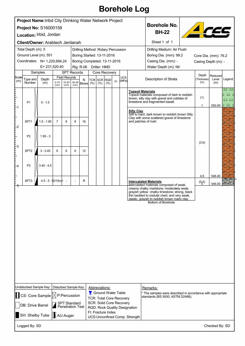
Silty ClayStiff to hard, dark brown to reddish brown SiltyClay with some scattered gravel of limestoneand patches of marl.
SPT2 6
7
546.00
546.40
550.00
Intercalated MaterialsIntercalated materials composed of weak,creamy chalky marlstone; moderately weak,grayish yellow chalky limestone; strong, blackthin bedded to nodular chert; and very weak,plastic, grayish to reddish brown marly clay.
(1)
Topsoil MaterialsTopsoil materials composed of dark to reddishbrown, silty clay with gravel and cobbles oflimestone and fragmented basalt.
SPT3
8
Bottom of Borehole
4.5 - 5
3.45 - 4.5
3 - 3.45
1.95 - 3
1.5 - 1.95
0 - 1.5
Iribd City Drinking Water Network Project
550/10cm
P2
-
6
8
(0.4)
(3.6)
1
P3
SPT1
P1
30-45(cm)
0-15(cm)
ReducedLevel(m)
DB: Drive Barrel
Arabtech Jerdanah
Samples
NBlows
4.6
6
SCR(%)
1
2
3
4
5
Logged By: SD
Description of Strata
Abbreviations:
Borehole Log
Core Recovery
(Thickness)(m)
LegendUCS(MPa)RQD
(%)
Scale(m) TCR
(%)15-30(cm)
P:Percussion
SPT:StandardPenetration Test
SPT Records
SH: Shelby Tube
Type andNumber
Project No:Irbid, Jordan
Client/Owner:
Borehole No.BH-22
* The samples were described in accordance with appropriatestandards (BS 5930; ASTM D2488).
Drilling Medium: Air FlushBoring Dia. (mm): 99.2Casing Dia. (mm): -Water Depth (m): Nil
N= 1,220,694.24
Depth(m)
Checked By: SD
R
12
16
-
Sheet 1 of 1
Project Name:S16000158
Location:
FI
Depth
Drilling Method: Rotary PercussionBoring Started: 13-11-2016Boring Completed: 13-11-2016Rig: R-06 Driller: HMD
Total Depth (m): 5Ground Level (m): 551Coordinates:
E= 231,520.40
Undisturbed Sample Key: Disturbed Sample Key: Remarks:
Field Records
CS: Core Sample
AU:Auger
Ground Water Table
Core Dia. (mm): 76.2Casing Depth (m): -
TCR: Total Core RecoverySCR: Solid Core RecoveryRQD: Rock Quality DesignationFI: Fracture IndexUCS:Unconfined Comp. Strength
Irbid City Drinking Water Network Proposed Project
S16000158-Rev.0-Interpretive Report
Appendix B
Generalized Subsurface Profiles
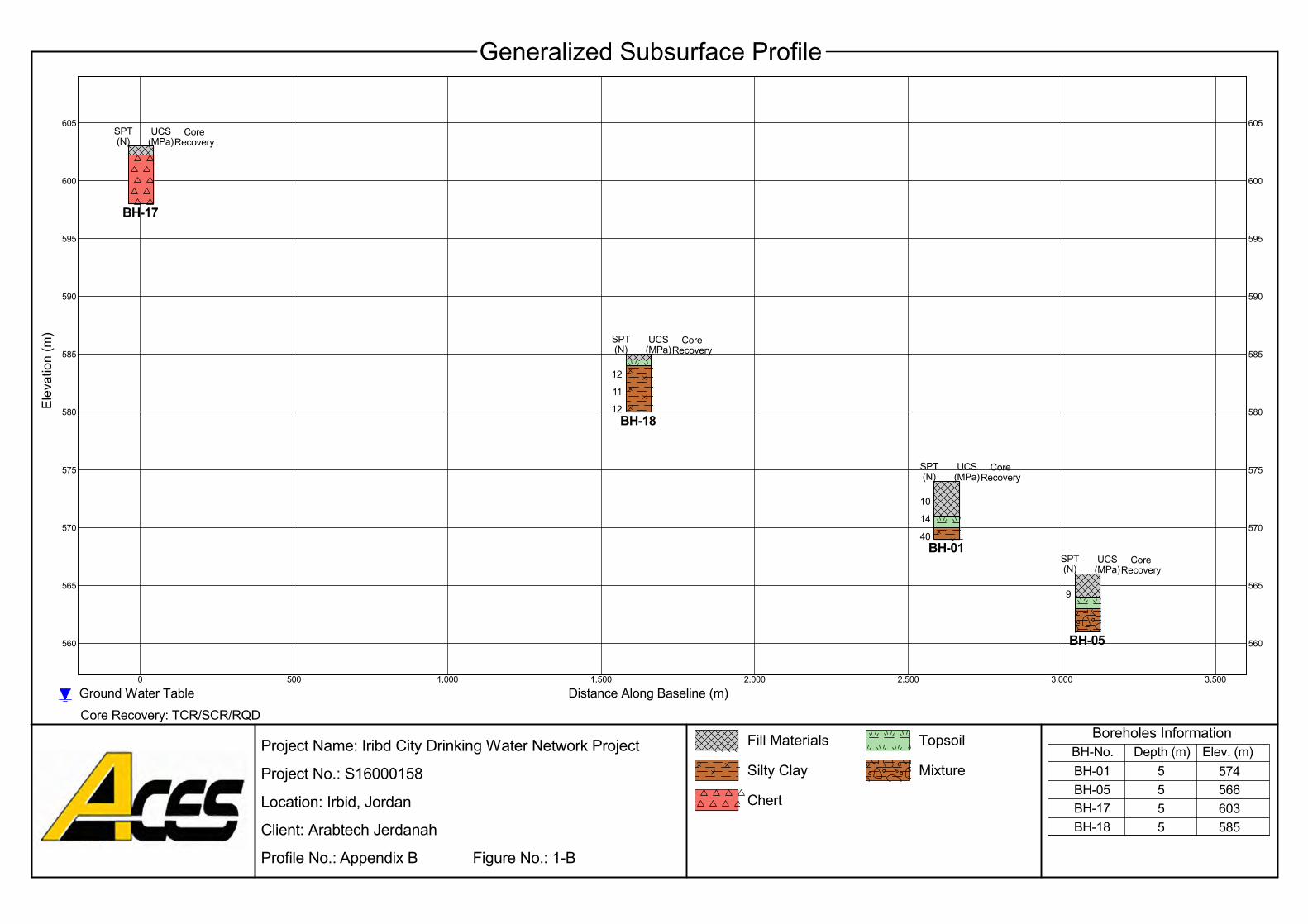
SPT(N)
575
580
585
590
595
600
605
10
14
BH-01
560
UCS(MPa)
CoreRecovery
9
SPT(N)
Project Name: Iribd City Drinking Water Network Project
Project No.: S16000158
Location: Irbid, Jordan
Client: Arabtech Jerdanah
Profile No.: Appendix B Figure No.: 1-B
CoreRecovery
BH-17
SPT(N)
UCS(MPa)
40
3,000
605
600
595
590
0 500 1,000 1,500
570
2,500
565
3,500
585
580
UCS(MPa)
575
CoreRecovery
570
565
560
2,000
585603
11
12BH-18
SPT(N)
5
Ground Water TableCore Recovery: TCR/SCR/RQD
Generalized Subsurface Profile
UCS(MPa)
CoreRecovery
555
574566
BH-05
Topsoil
Elev
atio
n (m
)
Mixture
Chert
Fill MaterialsElev. (m)
BH-01BH-05BH-17BH-18
BH-No.
Distance Along Baseline (m)
Boreholes Information
12
Silty ClayDepth (m)
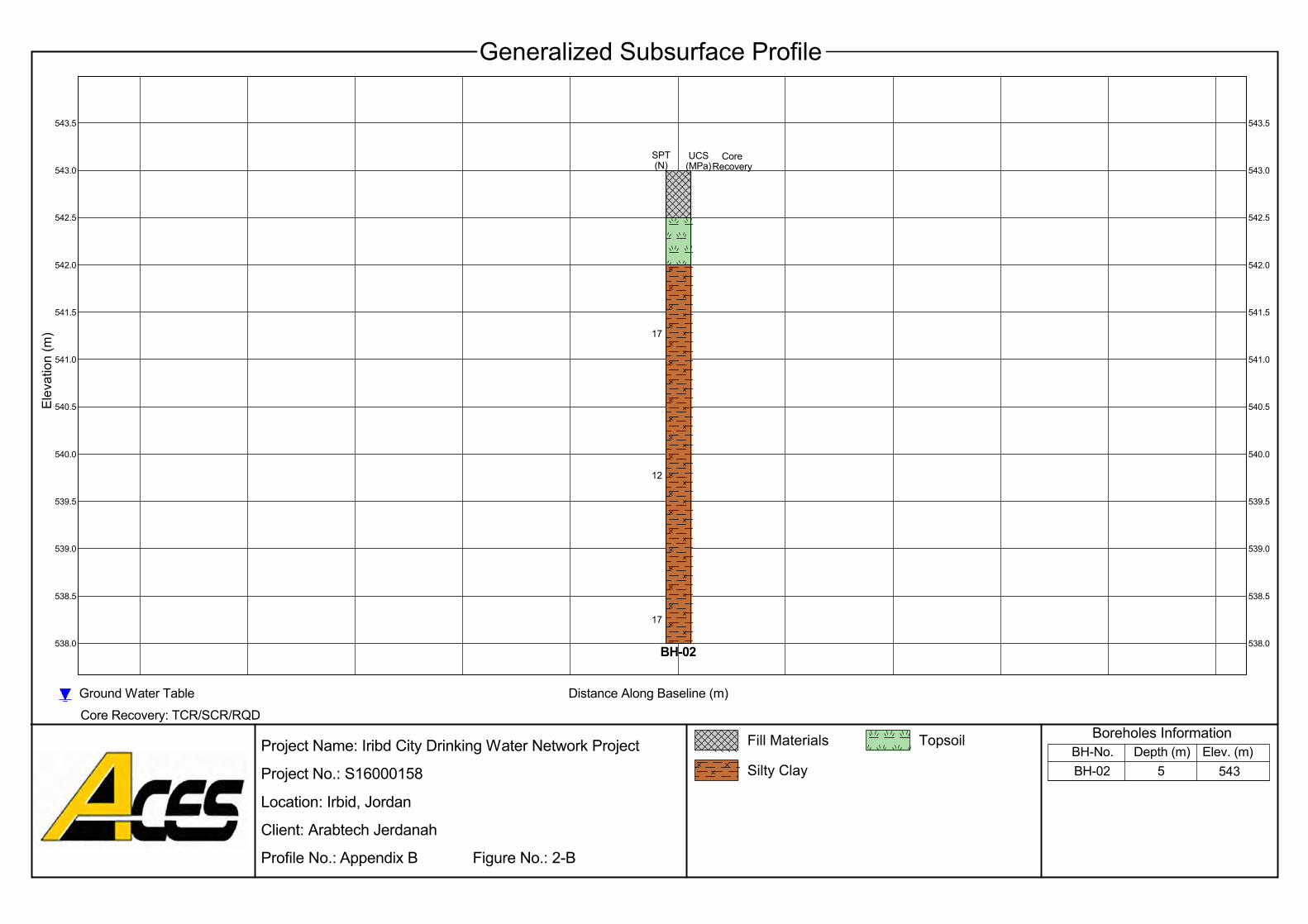
543.0
542.5
538.5
12
17
543.5 543.5
543.0
542.5
542.0
541.5
541.0
540.5
540.0
539.0
541.0
538.0
539.5
Elev
atio
n (m
)
Elev. (m)
Ground Water TableCore Recovery: TCR/SCR/RQD
Generalized Subsurface Profile
542.0
5 543BH-02
Project Name: Iribd City Drinking Water Network Project
Project No.: S16000158
Location: Irbid, Jordan
Client: Arabtech Jerdanah
Profile No.: Appendix B Figure No.: 2-B
Distance Along Baseline (m)
17
540.5
540.0
539.5
539.0
538.5
538.0BH-02
SPT(N)
CoreRecovery
Depth (m)BH-No.Boreholes InformationFill Materials Topsoil
Silty Clay
541.5
UCS(MPa)
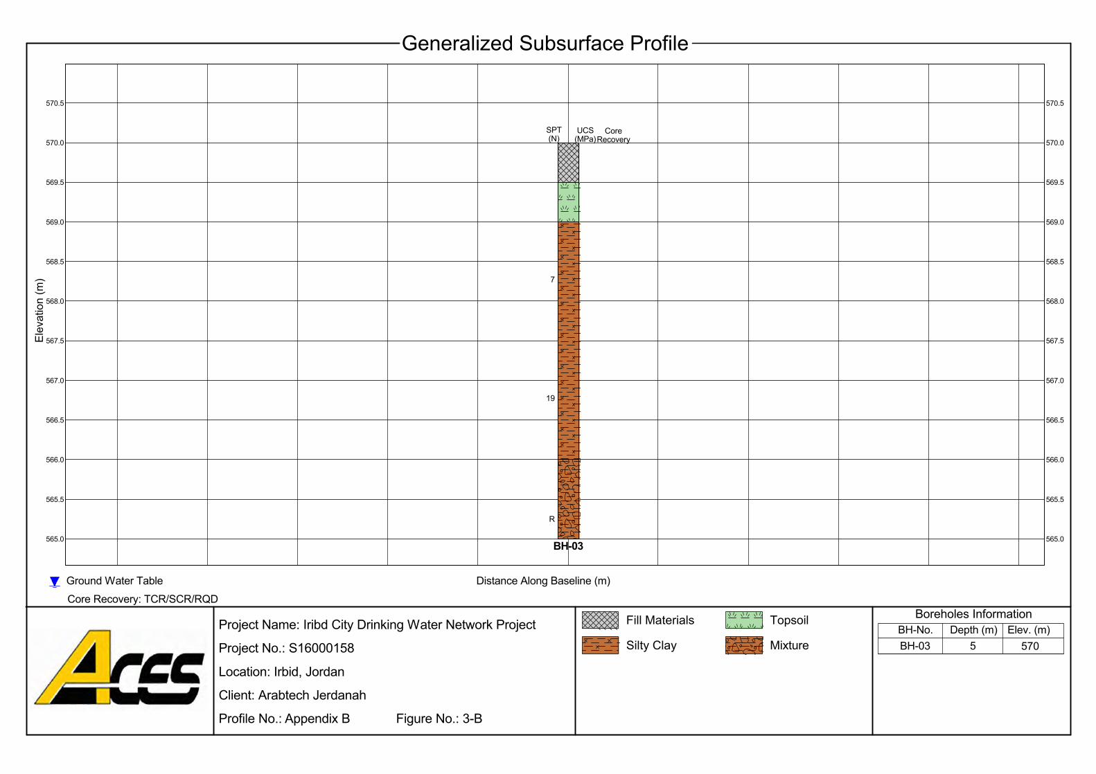
19
R
570.0
569.5
7
566.5
570.5
568.5
565.0
565.5
566.0
567.5
567.0
568.0
568.5
569.0
569.5
570.0
570.5
568.0
Elev. (m)
Ground Water TableCore Recovery: TCR/SCR/RQD
Generalized Subsurface Profile
569.0
Silty Clay
Elev
atio
n (m
)
5 570BH-03
Project Name: Iribd City Drinking Water Network Project
Project No.: S16000158
Location: Irbid, Jordan
Client: Arabtech Jerdanah
Profile No.: Appendix B Figure No.: 3-B
Distance Along Baseline (m)
567.5
567.0
566.5
566.0
565.5
565.0BH-03
SPT(N)
CoreRecovery
MixtureDepth (m)BH-No.
Boreholes InformationFill Materials Topsoil
UCS(MPa)
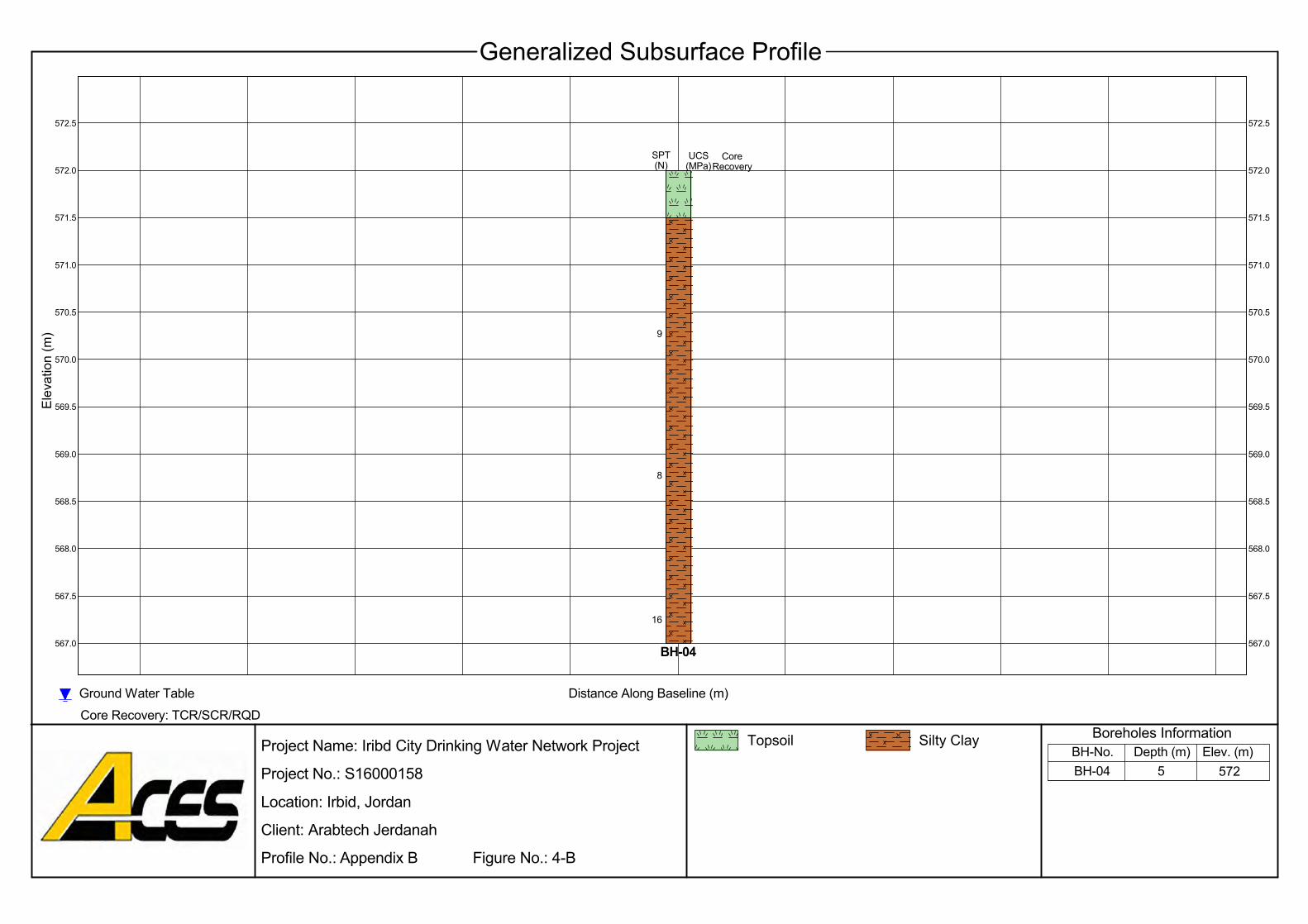
571.0
567.0
567.5
568.0
568.5
569.0
569.5
570.5
568.5
571.5
572.0
572.5
570.0
567.0
568.0
569.0
569.5
570.0
570.5
571.0
571.5
572.0
8
572.5
567.5
Elev. (m)
Ground Water TableCore Recovery: TCR/SCR/RQD
Generalized Subsurface Profile
Silty ClayTopsoil
Elev
atio
n (m
)
5 572BH-04
Project Name: Iribd City Drinking Water Network Project
Project No.: S16000158
Location: Irbid, Jordan
Client: Arabtech Jerdanah
Profile No.: Appendix B Figure No.: 4-B
UCS(MPa)
16
9
SPT(N)
CoreRecovery
Distance Along Baseline (m)
Depth (m)BH-No.Boreholes Information
BH-04
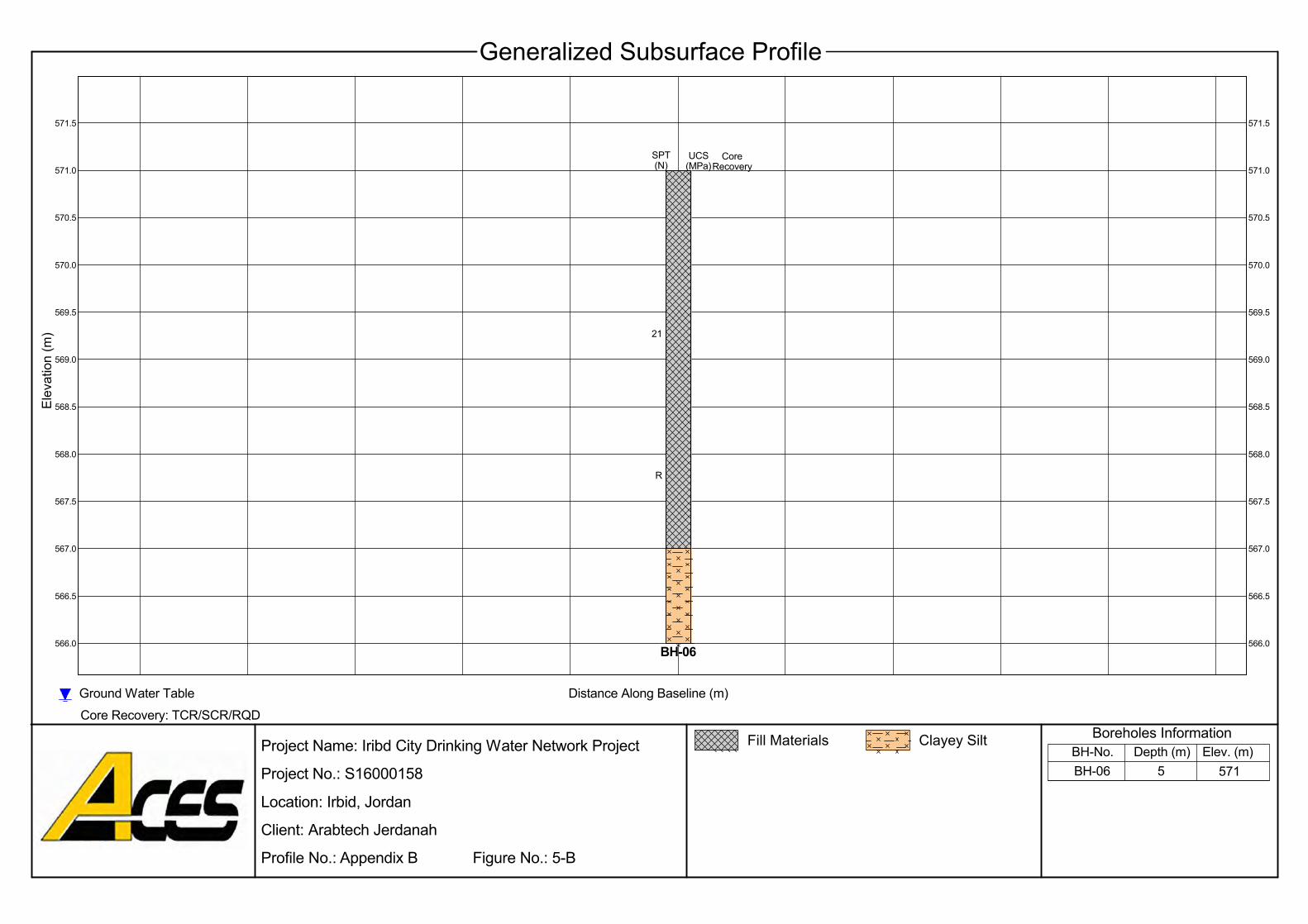
570.0
566.0
566.5
567.0
567.5
568.0
568.5
569.5
567.5
570.5
571.0
569.0
566.0
567.0
568.0
568.5
569.0
569.5
570.0
570.5
571.0
21
571.5
566.5
Elev. (m)
Ground Water TableCore Recovery: TCR/SCR/RQD
Generalized Subsurface Profile
571.5
Fill Materials
Elev
atio
n (m
)
5 571BH-06
Project Name: Iribd City Drinking Water Network Project
Project No.: S16000158
Location: Irbid, Jordan
Client: Arabtech Jerdanah
Profile No.: Appendix B Figure No.: 5-B
UCS(MPa)
R
Clayey Silt
SPT(N)
CoreRecovery
Distance Along Baseline (m)
Depth (m)BH-No.Boreholes Information
BH-06
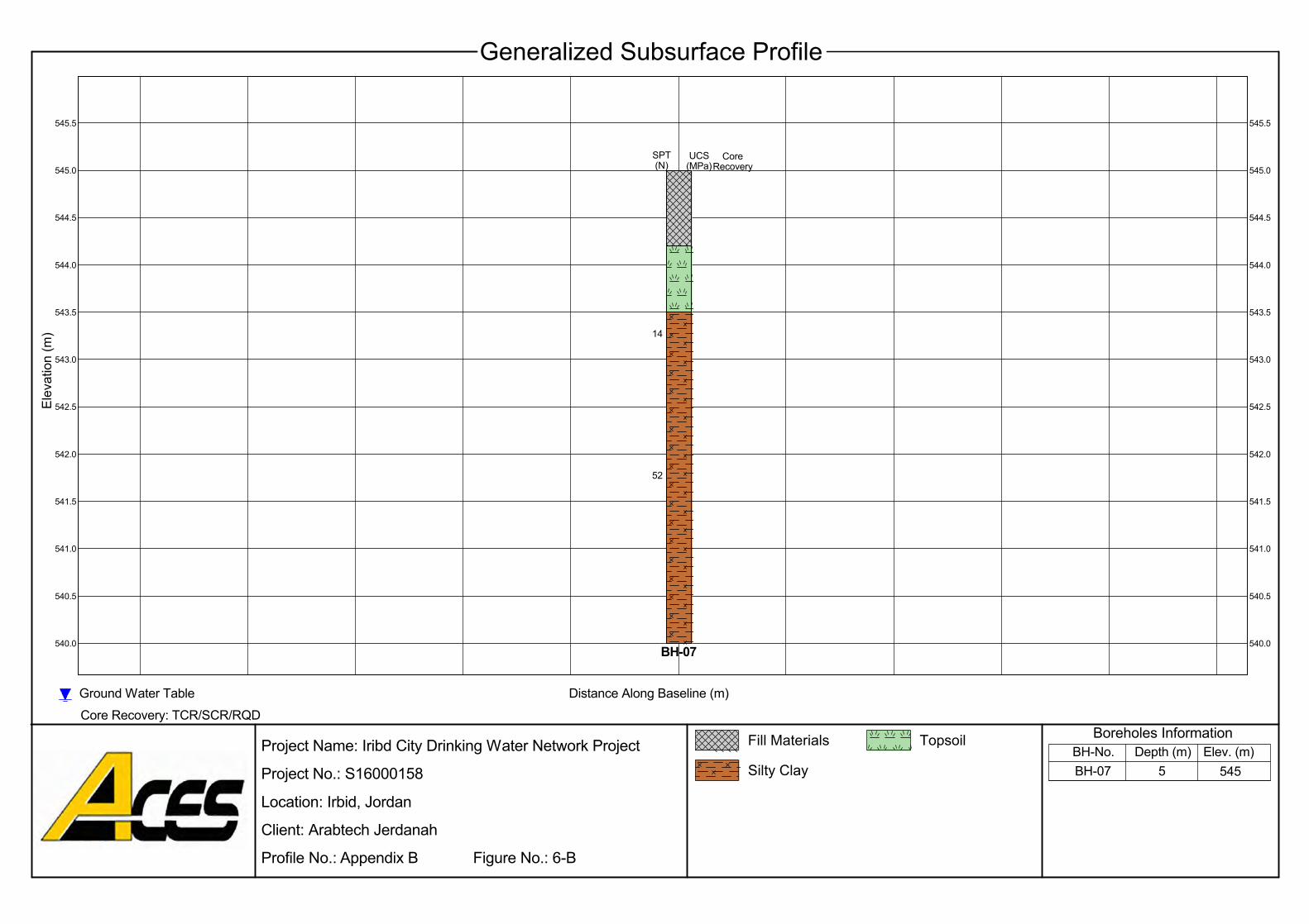
545.5
14
52
545.5
544.5
545.0545.0
544.5
544.0
543.5
543.0
542.5
542.0
541.5
541.0
540.5
543.5
543.0
540.0
544.0
Elev. (m)
Ground Water TableCore Recovery: TCR/SCR/RQD
Generalized Subsurface ProfileEl
evat
ion
(m)
5 545BH-07
Project Name: Iribd City Drinking Water Network Project
Project No.: S16000158
Location: Irbid, Jordan
Client: Arabtech Jerdanah
Profile No.: Appendix B Figure No.: 6-B
CoreRecovery
542.5
542.0
541.5
541.0
540.5
540.0BH-07
UCS(MPa)
Distance Along Baseline (m)
Depth (m)BH-No.Boreholes InformationFill Materials Topsoil
Silty Clay
SPT(N)
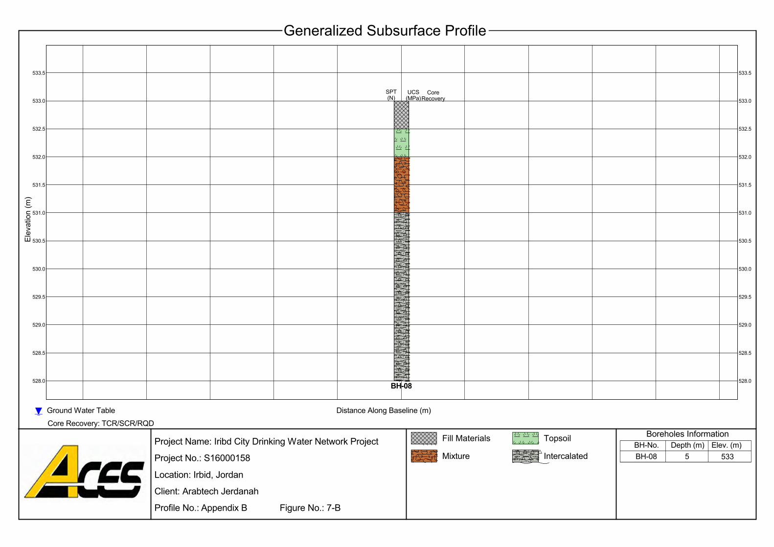
532.5
533.0
532.0
529.0
533.5 533.5
533.0
532.5
532.0
531.5
531.0
530.5
531.5
529.5
531.0
528.5
528.0
530.0
Elev. (m)
Ground Water TableCore Recovery: TCR/SCR/RQD
Generalized Subsurface Profile
Intercalated
Elev
atio
n (m
)
5 533BH-08
Project Name: Iribd City Drinking Water Network Project
Project No.: S16000158
Location: Irbid, Jordan
Client: Arabtech Jerdanah
Profile No.: Appendix B Figure No.: 7-B
Depth (m)
530.0
529.5
529.0
528.5
528.0BH-08
SPT(N)
UCS(MPa)
Distance Along Baseline (m)
530.5
BH-No.Boreholes InformationFill Materials Topsoil
Mixture
CoreRecovery
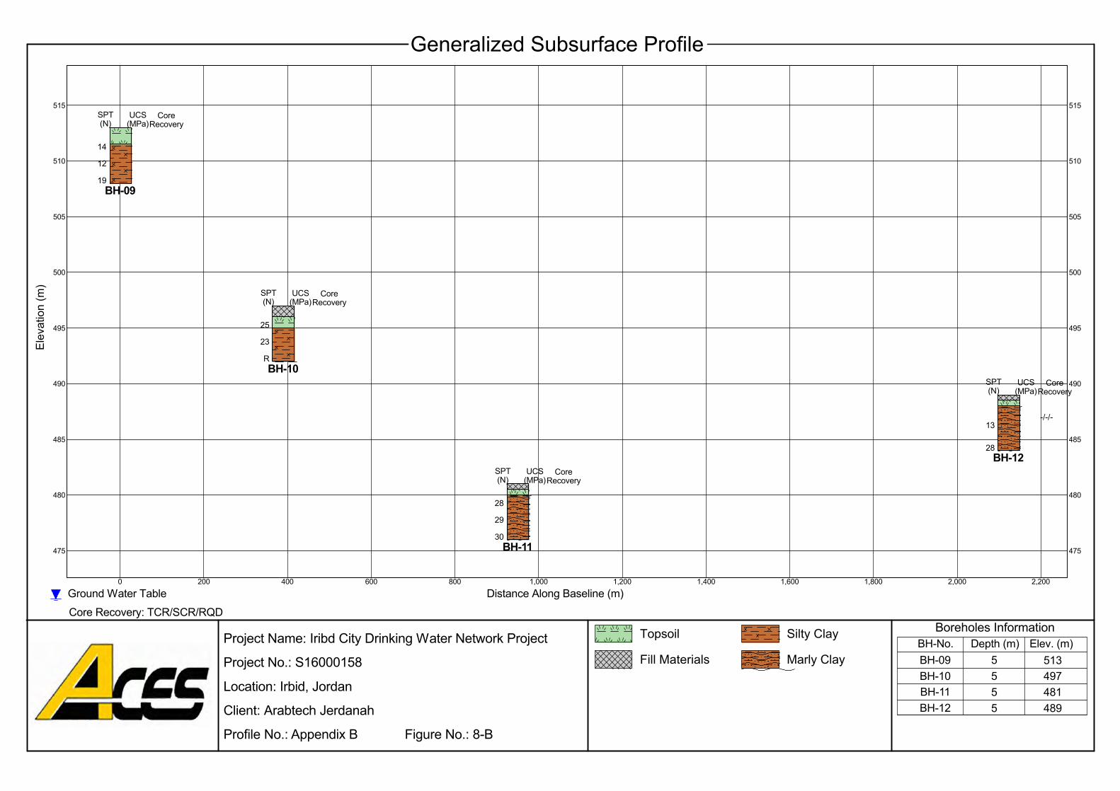
505
SPT(N)
BH-0919
12
14
UCS(MPa)
510
500
495
515
490
25
23
RBH-10
SPT(N)
UCS(MPa)
Project Name: Iribd City Drinking Water Network Project
Project No.: S16000158
Location: Irbid, Jordan
Client: Arabtech Jerdanah
Profile No.: Appendix B Figure No.: 8-B
28
29
30BH-11
CoreRecovery
515
0 200 400 600 800 1,000 1,200 1,400 1,600 1,800
480
2,200
485
510
505
CoreRecovery
500
SPT(N)
495
490
485
480
475 475
2,000
BH-12
489481497513
55
Ground Water Table
-/-/-
28
SPT(N)
UCS(MPa)
CoreRecovery
55
Core Recovery: TCR/SCR/RQD
Generalized Subsurface Profile
13
Elev
atio
n (m
)
UCS(MPa)
Elev. (m)Fill Materials Marly Clay
Topsoil Silty Clay
BH-09BH-10BH-11BH-12
CoreRecovery
Boreholes Information
Distance Along Baseline (m)
BH-No. Depth (m)
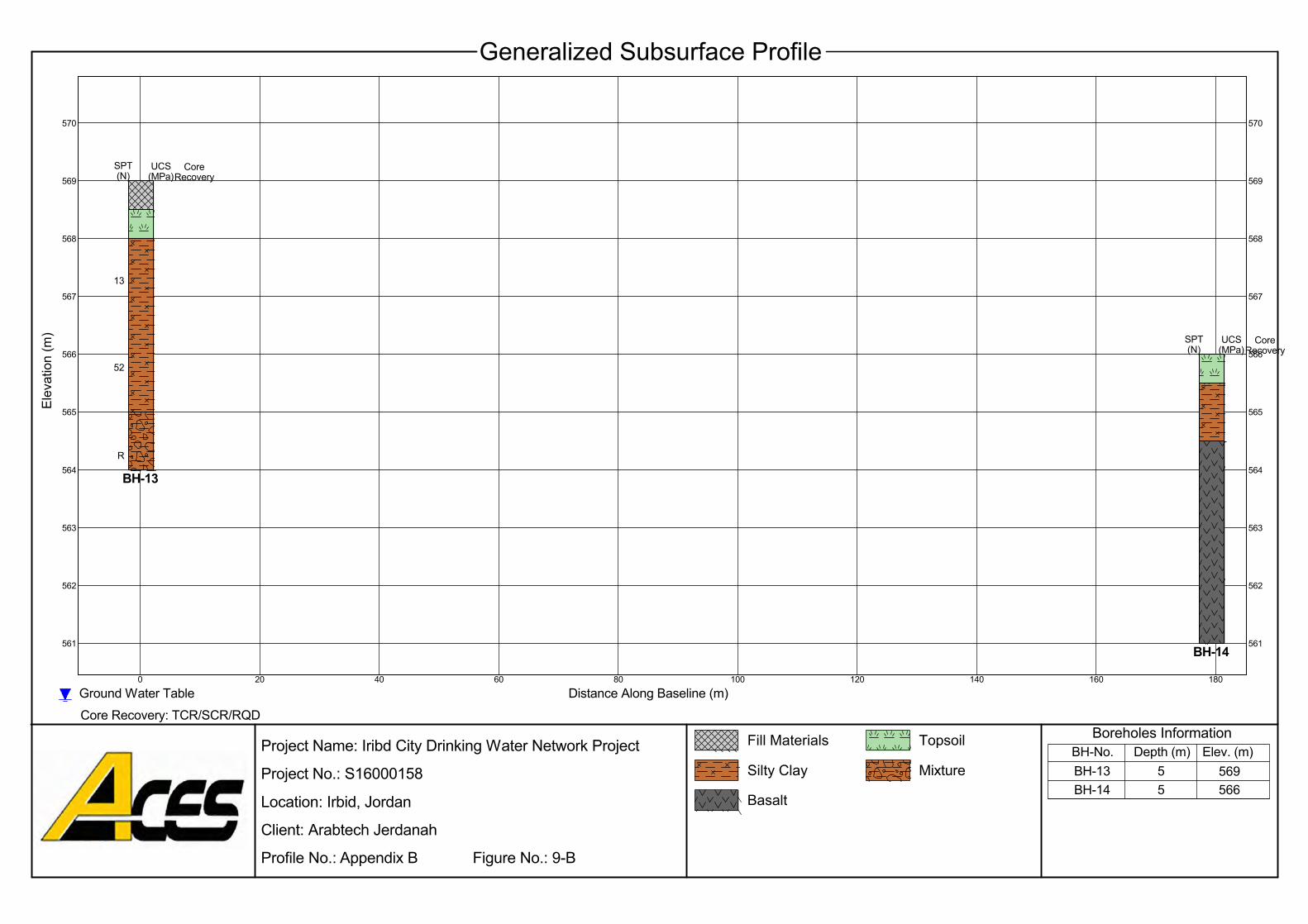
BH-13
Project Name: Iribd City Drinking Water Network Project
Project No.: S16000158
Location: Irbid, Jordan
Client: Arabtech Jerdanah
Profile No.: Appendix B Figure No.: 9-B
13
CoreRecovery
R
SPT(N)
UCS(MPa)
100 180
570
569
52
570
561
562
563
564
565
566
567
60
569
16014012080
568
40200
568
Elev. (m)
Ground Water TableCore Recovery: TCR/SCR/RQD
Generalized Subsurface Profile
567
5Basalt
Elev
atio
n (m
)
BH-13BH-14
569566
5BH-No.
566
565
564
563
562
561BH-14
SPT(N)
UCS(MPa)
CoreRecovery
Depth (m)Mixture
Fill Materials
Silty Clay
Distance Along Baseline (m)
Topsoil Boreholes Information

608.0
607.5
603.5
15
18
608.5 608.5
608.0
607.5
607.0
606.5
606.0
605.5
605.0
604.0
606.0
603.0
604.5
Elev
atio
n (m
)
Elev. (m)
Ground Water TableCore Recovery: TCR/SCR/RQD
Generalized Subsurface Profile
607.0
5 608BH-15
Project Name: Iribd City Drinking Water Network Project
Project No.: S16000158
Location: Irbid, Jordan
Client: Arabtech Jerdanah
Profile No.: Appendix B Figure No.: 10-B
Distance Along Baseline (m)
18
605.5
605.0
604.5
604.0
603.5
603.0BH-15
SPT(N)
CoreRecovery
Depth (m)BH-No.Boreholes InformationFill Materials Topsoil
Silty Clay
606.5
UCS(MPa)
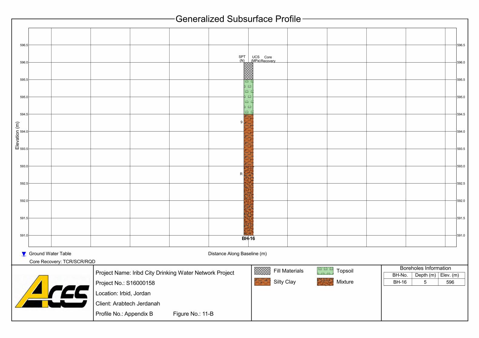
9
R
596.0
595.5
592.0
596.5 596.5
596.0
595.5
595.0
594.5
594.0
593.5
594.5
592.5
594.0
591.5
591.0
593.0
Elev. (m)
Ground Water TableCore Recovery: TCR/SCR/RQD
Generalized Subsurface Profile
595.0
Silty Clay
Elev
atio
n (m
)
5 596BH-16
Project Name: Iribd City Drinking Water Network Project
Project No.: S16000158
Location: Irbid, Jordan
Client: Arabtech Jerdanah
Profile No.: Appendix B Figure No.: 11-B
Distance Along Baseline (m)
593.5
593.0
592.5
592.0
591.5
591.0BH-16
SPT(N)
CoreRecovery
MixtureDepth (m)BH-No.
Boreholes InformationFill Materials Topsoil
UCS(MPa)

597.5
40
598.0
597.0
594.0
598.5 598.5
598.0
597.5
597.0
596.5
596.0
595.5
596.5
594.5
596.0
593.5
593.0
595.0
Elev. (m)
Ground Water TableCore Recovery: TCR/SCR/RQD
Generalized Subsurface Profile
Intercalated
Elev
atio
n (m
)
5 598BH-19
Project Name: Iribd City Drinking Water Network Project
Project No.: S16000158
Location: Irbid, Jordan
Client: Arabtech Jerdanah
Profile No.: Appendix B Figure No.: 12-B
Depth (m)
595.5
595.0
594.5
594.0
593.5
593.0BH-19
SPT(N)
UCS(MPa)
Distance Along Baseline (m)
BH-No.Boreholes InformationFill Materials Topsoil
Chalky Marl
CoreRecovery
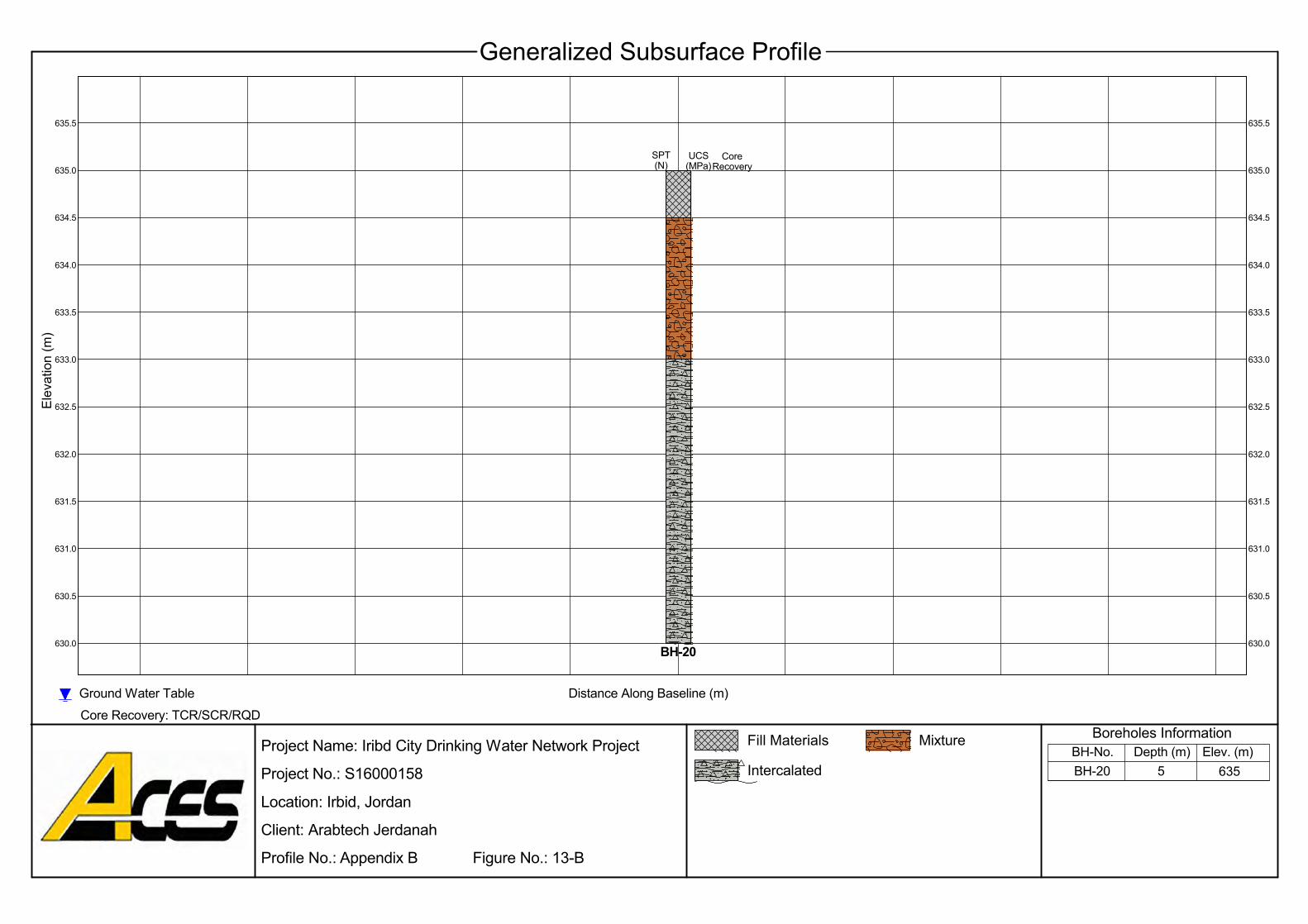
635.0
635.5635.5
634.5634.5
631.0
635.0
634.0
633.5
633.0
632.5
631.5
630.5
630.0
633.5
633.0
632.0
Elev. (m)
Ground Water TableCore Recovery: TCR/SCR/RQD
Generalized Subsurface Profile
634.0
Intercalated
Elev
atio
n (m
)
5 635BH-20
Project Name: Iribd City Drinking Water Network Project
Project No.: S16000158
Location: Irbid, Jordan
Client: Arabtech Jerdanah
Profile No.: Appendix B Figure No.: 13-B
CoreRecovery
632.5
632.0
631.5
631.0
630.5
630.0BH-20
UCS(MPa)
Distance Along Baseline (m)
Depth (m)BH-No.Boreholes InformationFill Materials Mixture
SPT(N)

549.0
548.5
544.5
12
9
549.5 549.5
549.0
548.5
548.0
547.5
547.0
546.5
546.0
545.0
547.0
544.0
545.5
Elev
atio
n (m
)
Elev. (m)
Ground Water TableCore Recovery: TCR/SCR/RQD
Generalized Subsurface Profile
548.0
5 549BH-21
Project Name: Iribd City Drinking Water Network Project
Project No.: S16000158
Location: Irbid, Jordan
Client: Arabtech Jerdanah
Profile No.: Appendix B Figure No.: 14-B
Distance Along Baseline (m)
16
546.5
546.0
545.5
545.0
544.5
544.0BH-21
SPT(N)
CoreRecovery
Depth (m)BH-No.Boreholes InformationFill Materials Topsoil
Silty Clay
547.5
UCS(MPa)
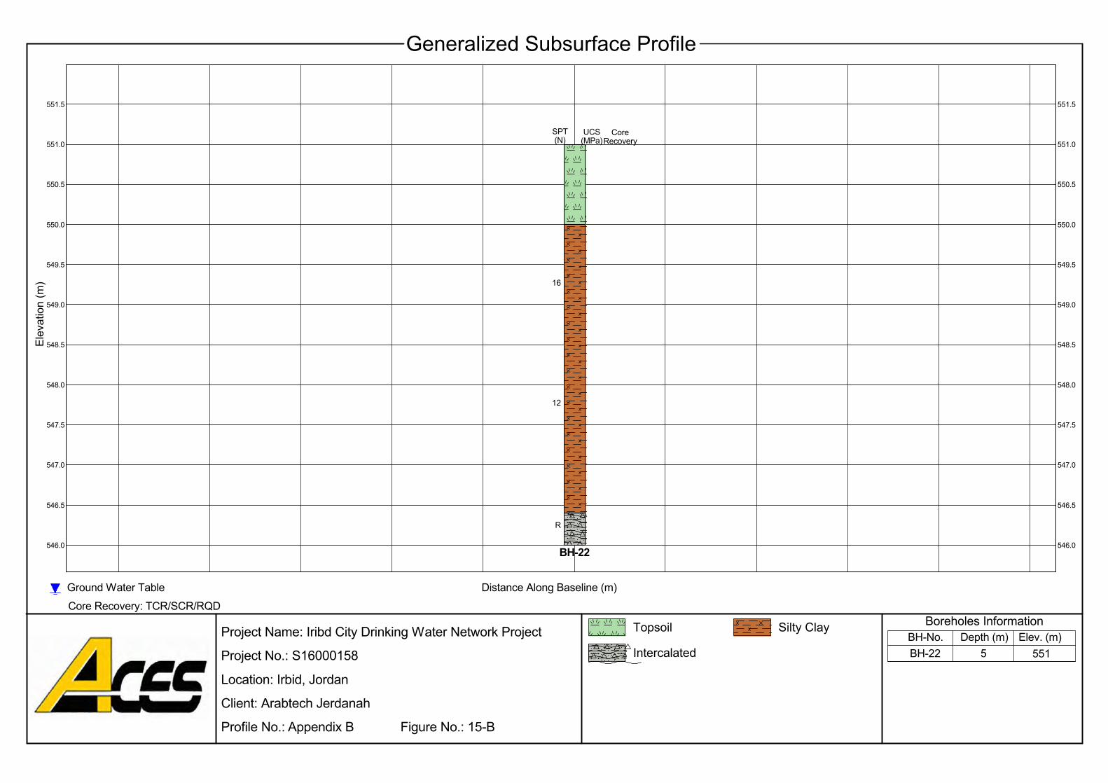
551.0
550.5
546.5
12
16
551.5 551.5
551.0
550.5
550.0
549.5
549.0
548.5
548.0
547.0
549.0
546.0
547.5
Elev
atio
n (m
)
Elev. (m)
Ground Water TableCore Recovery: TCR/SCR/RQD
Generalized Subsurface Profile
550.0
5 551BH-22
Project Name: Iribd City Drinking Water Network Project
Project No.: S16000158
Location: Irbid, Jordan
Client: Arabtech Jerdanah
Profile No.: Appendix B Figure No.: 15-B
Distance Along Baseline (m)
R
548.5
548.0
547.5
547.0
546.5
546.0BH-22
SPT(N)
CoreRecovery
Depth (m)BH-No.Boreholes InformationTopsoil Silty Clay
Intercalated
549.5
UCS(MPa)

Irbid City Drinking Water Network Proposed Project
S16000158-Rev.0-Interpretive Report
Appendix C Laboratory Test Results
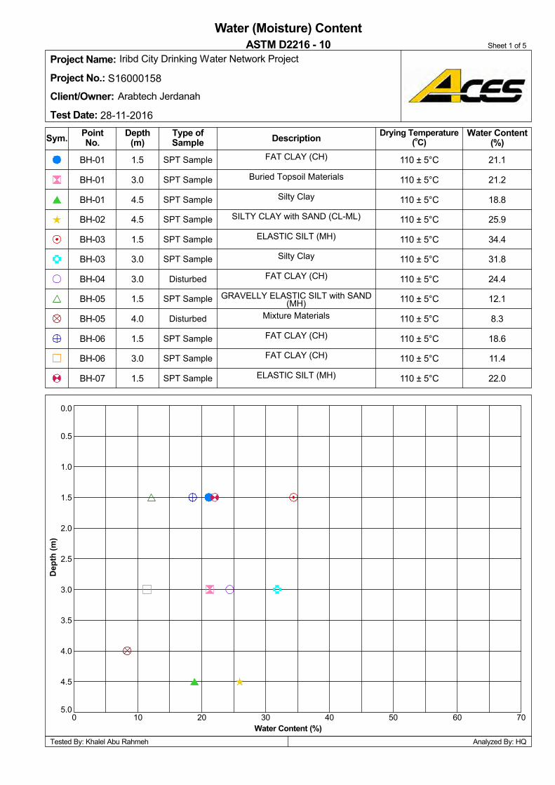
Dep
th (m
)
PointNo. Description
4.5
3.0
1.5
1.5
20100
0.0
Analyzed By: HQ
1.0
50
2.0
2.5
3.0
3.5
5.0
4.5
0.5
30 40
3.0
7060
4.0
Disturbed
110 ± 5°C
Tested By: Khalel Abu Rahmeh
Arabtech Jerdanah
Iribd City Drinking Water Network ProjectProject Name:Project No.: S16000158
Client/Owner:Test Date: 28-11-2016
SPT Sample
Sheet 1 of 5
SPT Sample
Water (Moisture) Content
SPT Sample
Disturbed
SPT Sample
SPT Sample
SPT Sample
SPT Sample
SPT Sample
SPT Sample
4.5
SPT Sample
FAT CLAY (CH)
ELASTIC SILT (MH)
FAT CLAY (CH)
FAT CLAY (CH)
Mixture Materials
GRAVELLY ELASTIC SILT with SAND(MH)
FAT CLAY (CH)
Silty Clay
ELASTIC SILT (MH)
SILTY CLAY with SAND (CL-ML)
Sym.
Buried Topsoil Materials
110 ± 5°C
Drying Temperature(oC)
Depth(m)
Type ofSample
Water Content(%)
ASTM D2216 - 10
Silty Clay
110 ± 5°C
BH-05
BH-05
BH-04
BH-03
BH-03
BH-02
BH-01
BH-01
BH-06
BH-07 1.5
3.0
1.5
4.0
1.5
3.0
Water Content (%)
BH-01
18.6
110 ± 5°C
110 ± 5°C
110 ± 5°C
110 ± 5°C
110 ± 5°C
110 ± 5°C
110 ± 5°C
110 ± 5°C
110 ± 5°C
BH-06
11.4
1.5
8.3
12.1
24.4
31.8
34.4
25.9
18.8
21.2
21.1
22.0

Dep
th (m
)
PointNo. Description
1.0
4.0
3.0
1.5
20100
0.0
Analyzed By: HQ
1.0
50
2.0
2.5
3.0
3.5
5.0
4.5
0.5
30 40
1.0
7060
4.0
SPT Sample
110 ± 5°C
Tested By: Mohammed Al-Zbeady
Arabtech Jerdanah
Iribd City Drinking Water Network ProjectProject Name:Project No.: S16000158
Client/Owner:Test Date: 27-11-2016
SPT Sample
Sheet 2 of 5
SPT Sample
Water (Moisture) Content
SPT Sample
SPT Sample
Disturbed
Disturbed
Disturbed
Disturbed
Disturbed
SPT Sample
3.0
SPT Sample
Silty Clay
LEAN CLAY (CL)
Clayey Marl to Marly Clay
Silty Clay
Silty Clay
Silty Clay
Silty Clay
ELASTIC SILT with GRAVEL (MH)
Intercalated Materials
Intercalated Materials
Sym.
Silty Clay
110 ± 5°C
Drying Temperature(oC)
Depth(m)
Type ofSample
Water Content(%)
ASTM D2216 - 10
CLAYEY SAND with GRAVEL (SC)
110 ± 5°C
BH-10
BH-09
BH-09
BH-09
BH-08
BH-08
BH-08
BH-07
BH-11
BH-11 3.0
1.5
3.0
1.5
4.5
3.0
Water Content (%)
BH-07
13.7
110 ± 5°C
110 ± 5°C
110 ± 5°C
110 ± 5°C
110 ± 5°C
110 ± 5°C
110 ± 5°C
110 ± 5°C
110 ± 5°C
BH-10
19.9
4.0
19.1
17.9
18.5
17.0
13.3
5.2
11.8
13.8
12.8
17.5
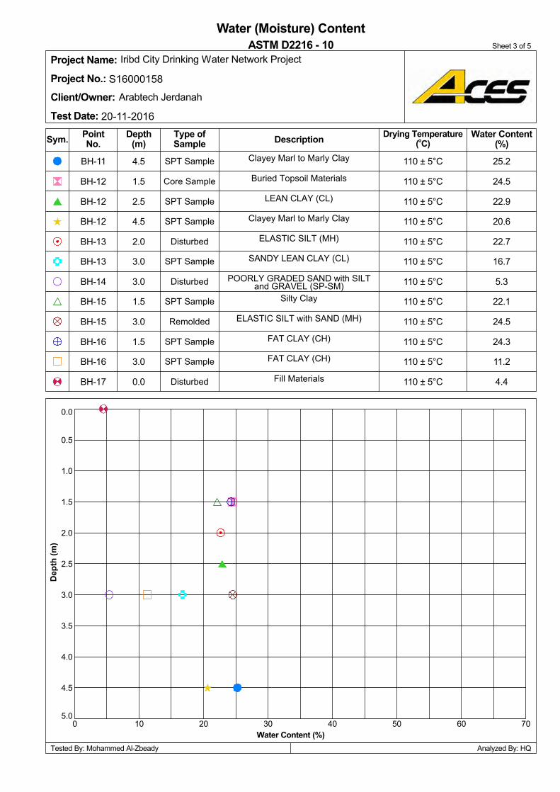
Dep
th (m
)
PointNo. Description
2.5
1.5
4.5
1.5
20100
0.0
Analyzed By: HQ
1.0
50
2.0
2.5
3.0
3.5
5.0
4.5
0.5
30 40
3.0
7060
4.0
Remolded
110 ± 5°C
Tested By: Mohammed Al-Zbeady
Arabtech Jerdanah
Iribd City Drinking Water Network ProjectProject Name:Project No.: S16000158
Client/Owner:Test Date: 20-11-2016
Disturbed
Sheet 3 of 5
SPT Sample
Water (Moisture) Content
SPT Sample
Disturbed
SPT Sample
Disturbed
SPT Sample
SPT Sample
Core Sample
SPT Sample
4.5
SPT Sample
Clayey Marl to Marly Clay
Fill Materials
FAT CLAY (CH)
FAT CLAY (CH)
ELASTIC SILT with SAND (MH)
Silty Clay
POORLY GRADED SAND with SILTand GRAVEL (SP-SM)
SANDY LEAN CLAY (CL)
ELASTIC SILT (MH)
Clayey Marl to Marly Clay
Sym.
Buried Topsoil Materials
110 ± 5°C
Drying Temperature(oC)
Depth(m)
Type ofSample
Water Content(%)
ASTM D2216 - 10
LEAN CLAY (CL)
110 ± 5°C
BH-15
BH-15
BH-14
BH-13
BH-13
BH-12
BH-12
BH-12
BH-16
BH-17 0.0
3.0
1.5
3.0
1.5
3.0
Water Content (%)
BH-11
24.3
110 ± 5°C
110 ± 5°C
110 ± 5°C
110 ± 5°C
110 ± 5°C
110 ± 5°C
110 ± 5°C
110 ± 5°C
110 ± 5°C
BH-16
11.2
2.0
24.5
22.1
5.3
16.7
22.7
20.6
22.9
24.5
25.2
4.4
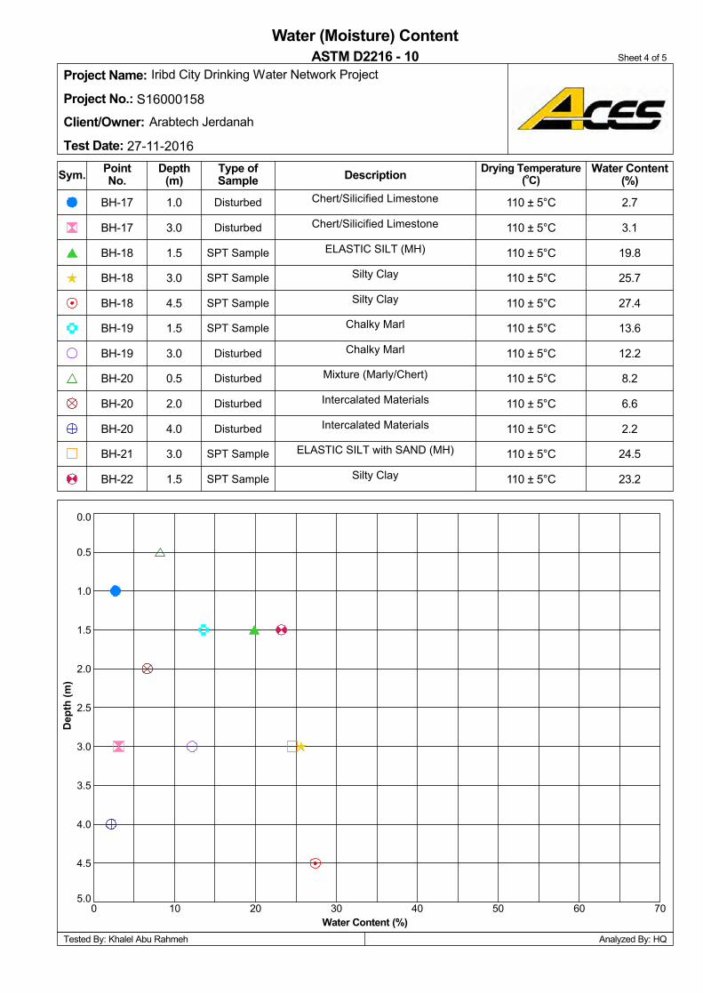
Dep
th (m
)
PointNo. Description
1.5
3.0
1.0
1.5
20100
0.0
Analyzed By: HQ
1.0
50
2.0
2.5
3.0
3.5
5.0
4.5
0.5
30 40
1.5
7060
4.0
Disturbed
110 ± 5°C
Tested By: Khalel Abu Rahmeh
Arabtech Jerdanah
Iribd City Drinking Water Network ProjectProject Name:Project No.: S16000158
Client/Owner:Test Date: 27-11-2016
SPT Sample
Sheet 4 of 5
Disturbed
Water (Moisture) Content
Disturbed
Disturbed
SPT Sample
SPT Sample
SPT Sample
SPT Sample
Disturbed
Disturbed
3.0
SPT Sample
Chert/Silicified Limestone
Silty Clay
ELASTIC SILT with SAND (MH)
Intercalated Materials
Intercalated Materials
Mixture (Marly/Chert)
Chalky Marl
Chalky Marl
Silty Clay
Silty Clay
Sym.
Chert/Silicified Limestone
110 ± 5°C
Drying Temperature(oC)
Depth(m)
Type ofSample
Water Content(%)
ASTM D2216 - 10
ELASTIC SILT (MH)
110 ± 5°C
BH-20
BH-20
BH-19
BH-19
BH-18
BH-18
BH-18
BH-17
BH-21
BH-22 1.5
3.0
4.0
2.0
0.5
3.0
Water Content (%)
BH-17
2.2
110 ± 5°C
110 ± 5°C
110 ± 5°C
110 ± 5°C
110 ± 5°C
110 ± 5°C
110 ± 5°C
110 ± 5°C
110 ± 5°C
BH-20
24.5
4.5
6.6
8.2
12.2
13.6
27.4
25.7
19.8
3.1
2.7
23.2
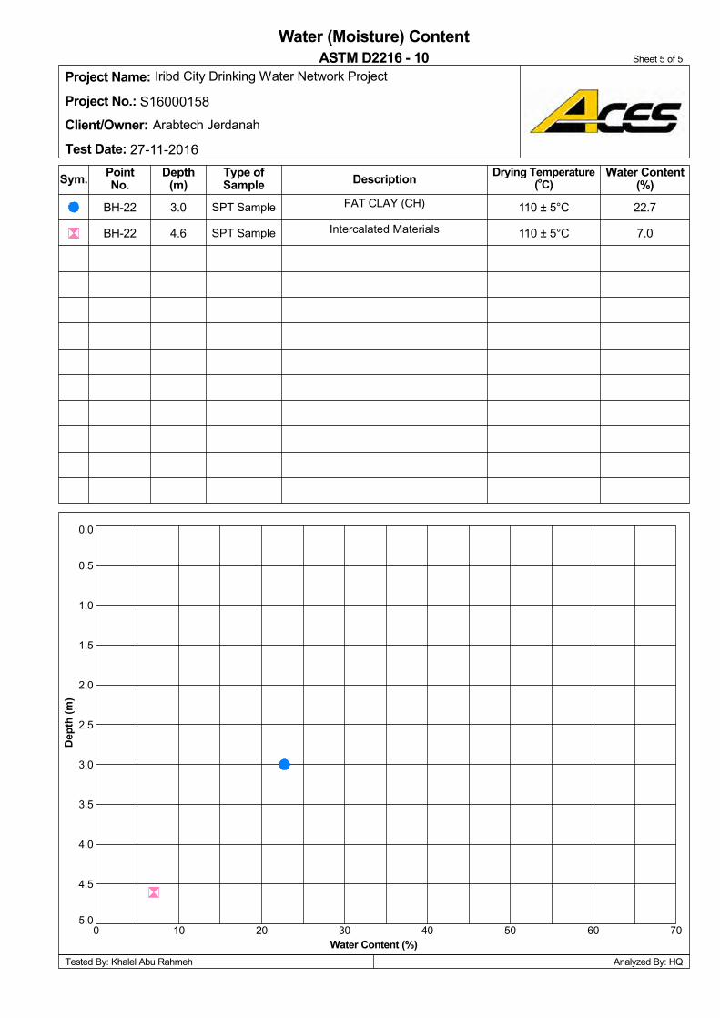
600
Analyzed By: HQ
70
4.0
0.0
0.5
1.0
1.5
2.0
2.5
20
3.5
50
4.5
5.010 30 40
3.0
Sheet 5 of 5
110 ± 5°C
SPT Sample
SPT Sample
Project Name:Project No.: S16000158
Client/Owner:Test Date: 27-11-2016
Iribd City Drinking Water Network Project
Arabtech Jerdanah
Tested By: Khalel Abu Rahmeh
7.0
Sym.
22.7
Water (Moisture) ContentASTM D2216 - 10
Water Content(%)
Type ofSample
Depth(m)
Drying Temperature(oC)
FAT CLAY (CH)
Intercalated Materials
Water Content (%)
Dep
th (m
)
DescriptionPointNo.
110 ± 5°C
3.0
4.6
BH-22
BH-22
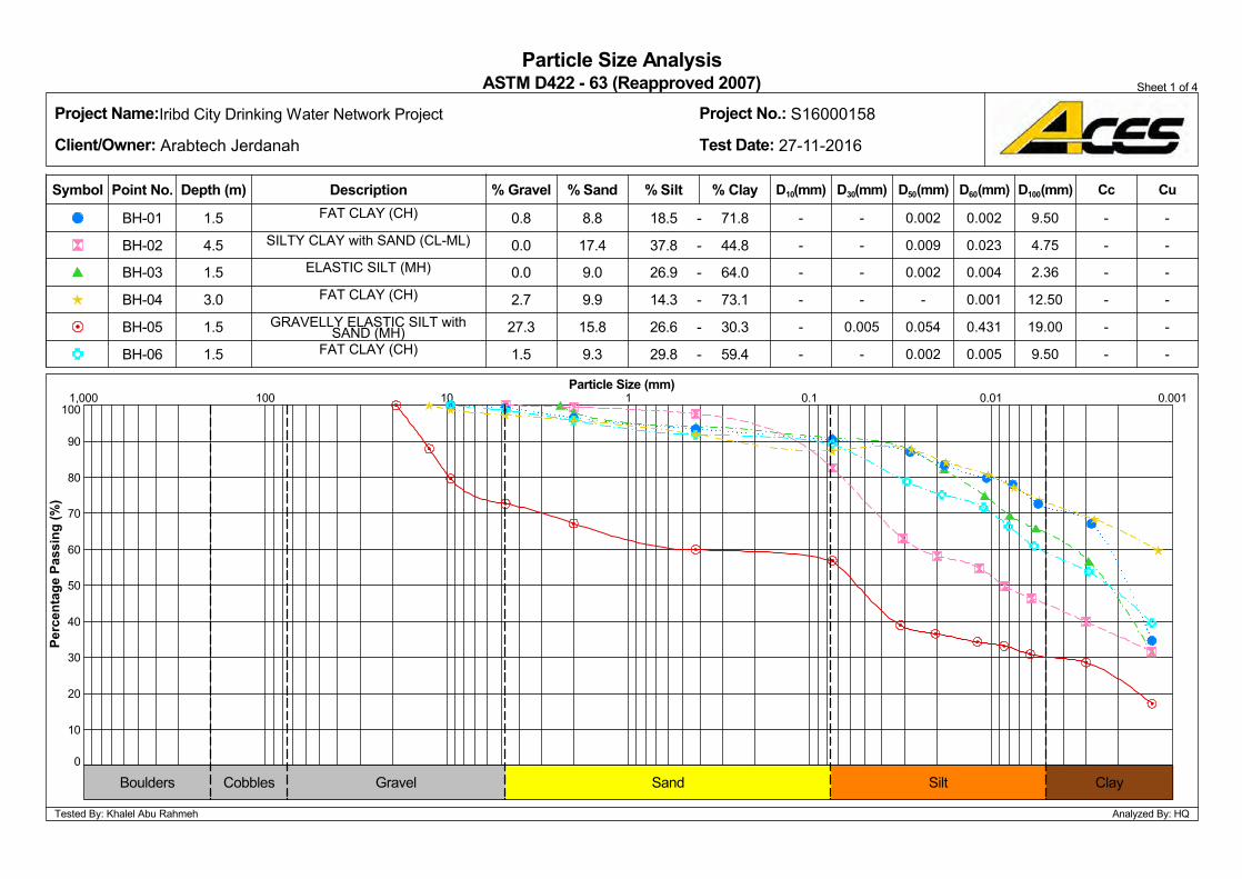
1,000
40
60
70
80
90
100
50
100 10 1 0.1 0.01
10
20
0.001
30
0
0.0
-
-
-
-
-
-
Particle Size Analysis
BH-05
0.8
0.054
0.0
2.7
27.3
1.5
8.8
17.4
9.0
ASTM D422 - 63 (Reapproved 2007)
BH-06
Test Date: 27-11-2016
D30(mm)
0.002
Depth (m)
0.002
0.009
0.002
-
9.3
0.005
9.9
1.5
3.0
1.5
1.5
-
-
1.5
-
- -
71.8
44.8
64.0
73.1
30.3
59.4
Iribd City Drinking Water Network Project
--
18.5
37.8
26.9
14.3
26.6
29.8
4.5 -
15.8
-
-
-
-
-
-
-
-
-
Sheet 1 of 4
0.002
Project No.: S16000158
0.004
BH-04
0.431
0.005
-
Project Name:
Client/Owner: Arabtech Jerdanah
Analyzed By: HQ
Cc
-
0.001 -
-
-
CuD100(mm)D60(mm)D50(mm)
-
% Clay
ELASTIC SILT (MH)
FAT CLAY (CH)
GRAVELLY ELASTIC SILT withSAND (MH)
FAT CLAY (CH)
D10(mm)
Perc
enta
ge P
assi
ng (%
)
SILTY CLAY with SAND (CL-ML)
DescriptionPoint No.Symbol
BH-01
BH-02
BH-03
0.023
Particle Size (mm)
% Silt% Sand% GravelFAT CLAY (CH)
Tested By: Khalel Abu Rahmeh
9.50
9.50
19.00
12.50
2.36
4.75
Boulders ClaySandCobbles Gravel Silt
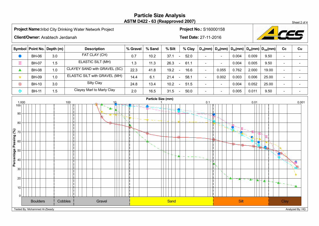
70
10
30
0
40
50
60
20
80
90
1001 0.1 0.0010.011,000
0.7
6.1
-
-
-
-
-
-0.005
ASTM D422 - 63 (Reapproved 2007)
0.004
1.3
22.3
14.4
24.8
2.0
10.2
11.3
BH-09
Particle Size Analysis
BH-10
100 10
Project No.: S16000158
Test Date: 27-11-2016
D30(mm)
13.4
Depth (m)
0.004
0.004
0.762
0.003
-
41.81.0
1.0
3.0
1.5
-
-
3.0
0.002
- -
52.0
61.1
16.6
58.1
51.5
50.0
Iribd City Drinking Water Network Project
0.055-
16.5
37.1
26.3
19.2
21.4
10.2
31.5
1.5 -
BH-11
-
-
-
-
-
-
-
-
-
0.052
D100(mm)
0.009
BH-08 2.000
0.006
Sheet 2 of 4
Cc
Project Name:
Client/Owner: Arabtech Jerdanah
Analyzed By: HQ
D50(mm) D60(mm)
-
-
-
-
-
-
Cu
0.005
Clayey Marl to Marly Clay
ELASTIC SILT (MH)
ELASTIC SILT with GRAVEL (MH)
Silty Clay
0.011
BH-07
9.50
BH-06 FAT CLAY (CH)
Perc
enta
ge P
assi
ng (%
)
Symbol Point No. Description % Clay D10(mm)% Silt% Sand
CLAYEY SAND with GRAVEL (SC)
25.00
Particle Size (mm)
Tested By: Mohammed Al-Zbeady
9.50
9.50
19.00
25.00
% Gravel
Cobbles Sand ClayGravelBoulders Silt
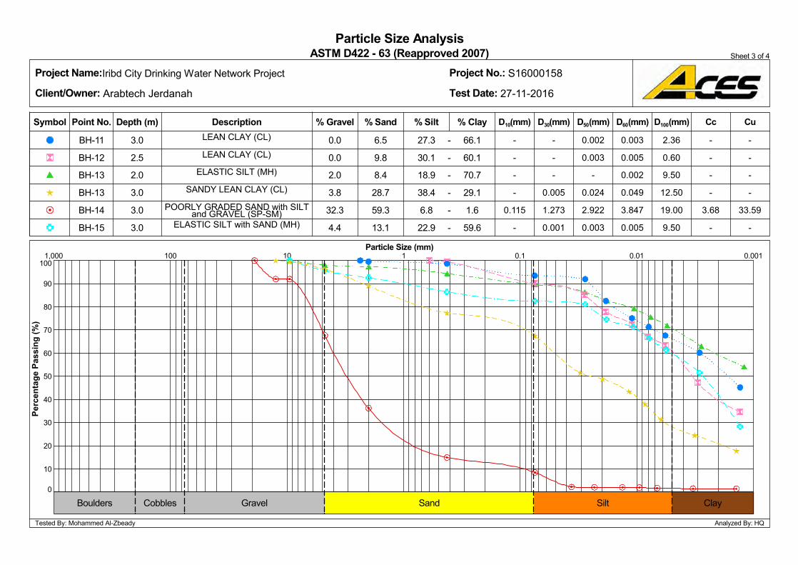
100
90
80
60
1,000
50
70
100 10 1 0.1 0.001
20
30
0.01
40
0
10
2.0
-
-
-
3.68
-
Particle Size AnalysisASTM D422 - 63 (Reapproved 2007)
59.3
0.0
0.003
3.8
32.3
4.4
6.5
9.8
8.4
BH-15
0.0
Project Name: Project No.: S16000158
-
D30(mm)Depth (m)
0.002
0.003
-
0.024
2.922
13.1 0.001
2.0
3.0
3.0
3.0
-
-
-
28.7
1.273
-
66.1
60.1
70.7
29.1
1.6
59.6
Iribd City Drinking Water Network Project
0.005-
27.3
30.1
18.9
38.4
6.8
22.9
-
2.5
-
3.0
-
-
-
-
-
-
0.115
-
D10(mm)
Sheet 3 of 4
0.003
0.005
Test Date: 27-11-2016
0.049
BH-14
0.005
-
Client/Owner: Arabtech Jerdanah
Analyzed By: HQ
Cc
-
-
3.847 33.59
-
CuD100(mm)D60(mm)D50(mm)
-
Description
SANDY LEAN CLAY (CL)
POORLY GRADED SAND with SILTand GRAVEL (SP-SM)
ELASTIC SILT with SAND (MH)
% Silt
ELASTIC SILT (MH)
% Clay
Perc
enta
ge P
assi
ng (%
)
Point No.Symbol
BH-11
BH-12
BH-13
BH-13
0.002
Tested By: Mohammed Al-Zbeady
% Sand% Gravel
Particle Size (mm)
LEAN CLAY (CL)
LEAN CLAY (CL)
9.50
19.00
0.60
9.50
12.50
2.36
Boulders ClaySandCobbles Gravel Silt
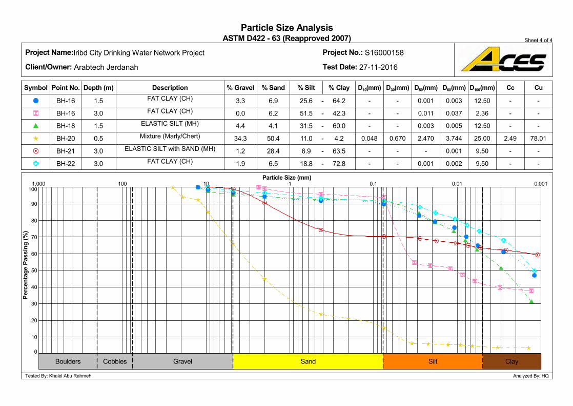
80
70
60
50
30
90
20
1,000
40
10010 1 0.1 0.001
0
0.01
10
0.0
-
-
-
2.49
-
-
Particle Size Analysis
BH-21
3.3
-
4.4
34.3
1.2
1.9
6.9
6.2
4.1
ASTM D422 - 63 (Reapproved 2007)
BH-22
Project Name:
100
Test Date: 27-11-2016
D30(mm)
0.001
Depth (m)
0.001
0.011
0.003
2.470
6.5
-
50.4
1.5
0.5
3.0
3.0
-
-
1.5
0.670
- -
64.2
42.3
60.0
4.2
63.5
72.8
Iribd City Drinking Water Network Project
--
25.6
51.5
31.5
11.0
6.9
18.8
3.0 -
28.4
-
-
-
-
-
-
0.048
-
-
Sheet 4 of 4
D50(mm)
0.003
Project No.: S16000158
0.005
BH-20
0.001
0.002
-
Client/Owner: Arabtech Jerdanah
Analyzed By: HQ
-
-
78.01
-
-
CuD100(mm)D60(mm)
3.744
Cc
Perc
enta
ge P
assi
ng (%
)
Mixture (Marly/Chert)
FAT CLAY (CH)
BH-18
D10(mm)
FAT CLAY (CH) 0.037ELASTIC SILT (MH)
BH-16
Symbol Point No. % ClayDescription
BH-16
Particle Size (mm)
% Silt% Sand% Gravel
ELASTIC SILT with SAND (MH)
FAT CLAY (CH)
Tested By: Khalel Abu Rahmeh
12.50
2.36
12.50
25.00
9.50
9.50
Sand ClayCobbles GravelBoulders Silt
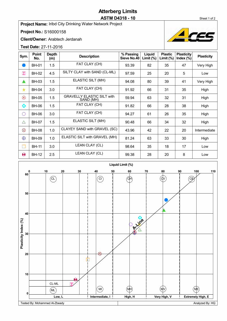
20
35
CL
ML
CL-ML
32
BH-12
BH-11
BH-09
BH-08
BH-07
BH-06
BH-06
BH-05
BH-04
BH-03
BH-02
94.27
ASTM D4318 - 10
20
18
33
22
34
97.59
94.08
91.92
59.94
39
26
31
90.48
43.96
81.24
98.64
BH-01
99.38
82
28
93.39
91.82
60
50
40
30
20
10
0
0 10
80
66
Plasticity
CE
1101009080706050403020
CV
Intermediate, I
FAT CLAY (CH)
GRAVELLY ELASTIC SILT withSAND (MH)
FAT CLAY (CH)
ELASTIC SILT (MH)
SILTY CLAY with SAND (CL-ML)
FAT CLAY (CH)
LiquidLimit (%)
PlasticLimit (%)
25
High, H
CLAYEY SAND with GRAVEL (SC)
MV
Tested By: Mohammed Al-Zbeady
Sym.
Atterberg Limits
2.5
3.0
1.0
Project Name:Project No.: S16000158
Client/Owner:Test Date: 27-11-2016
17
30
20
32
35
38
31
35
41
5
47
A-Line
FAT CLAY (CH)
Iribd City Drinking Water Network Project
ELASTIC SILT (MH)
Low, L
CH
LEAN CLAY (CL)
LEAN CLAY (CL)
ELASTIC SILT with GRAVEL (MH)
3.0
Arabtech Jerdanah
Very High
1.0
CI
Low
Low
High
Intermediate
High
High
High
High
Low
Very High
ME
Very High, V Extremely High, E
28
35
63
42
66
61
66
63 High
Sheet 1 of 2
8
1.5
1.5
3.0
1.5
4.5
1.5
Analyzed By: HQ
1.5
DescriptionDepth(m)
Plas
ticity
Inde
x (%
)
MH
% PassingSieve No.40
PlasticityIndex (%)
MI
PointNo.
Liquid Limit (%)

BH-18
CL
ML
CL-ML
BH-21
21
BH-16
BH-16
BH-15
BH-14
BH-13
BH-13
BH-22
91.86
33
28
28
36
31
ASTM D4318 - 10
94.34
77.43
14.91
86.36
35
95.76
92.69
74.33
93.39
70
34
NP
60
50
40
30
20
10
CE
10
0
100
Plasticity
NP
CV
74
1100 9080706050403020
Intermediate, I
1.5
POORLY GRADED SAND withSILT and GRAVEL (SP-SM)
SANDY LEAN CLAY (CL)
ELASTIC SILT (MH)
LiquidLimit (%)
PlasticLimit (%)
FAT CLAY (CH)
High, H
FAT CLAY (CH)
MV
Tested By: Khalel Abu Rahmeh
Sym.
Atterberg Limits
3.0
40
37
30
30
28
38
NP
19
35
A-Line
Arabtech Jerdanah
ELASTIC SILT with SAND (MH)
Project Name:Project No.: S16000158
Client/Owner:Test Date: 27-11-2016
3.0
Low, L
CH
FAT CLAY (CH)
ELASTIC SILT with SAND (MH)
ELASTIC SILT (MH)
Iribd City Drinking Water Network Project
Very High
3.0
Analyzed By: HQ
CI
High
Very High
High
Liquid Limit (%)
High
PointNo.
Non Plastic
Intermediate
High
ME
Very High, V Extremely High, E
68
71
63
58
56
High
Sheet 2 of 2
1.5
3.0
3.0
3.0
2.0
37
DescriptionDepth(m)
Plas
ticity
Inde
x (%
)
MH
% PassingSieve No.40
PlasticityIndex (%)
MI
Irbid City Drinking Water Network Proposed Project
S16000158-Rev.0-Interpretive Report
Appendix D Chemical Standards and Requirements
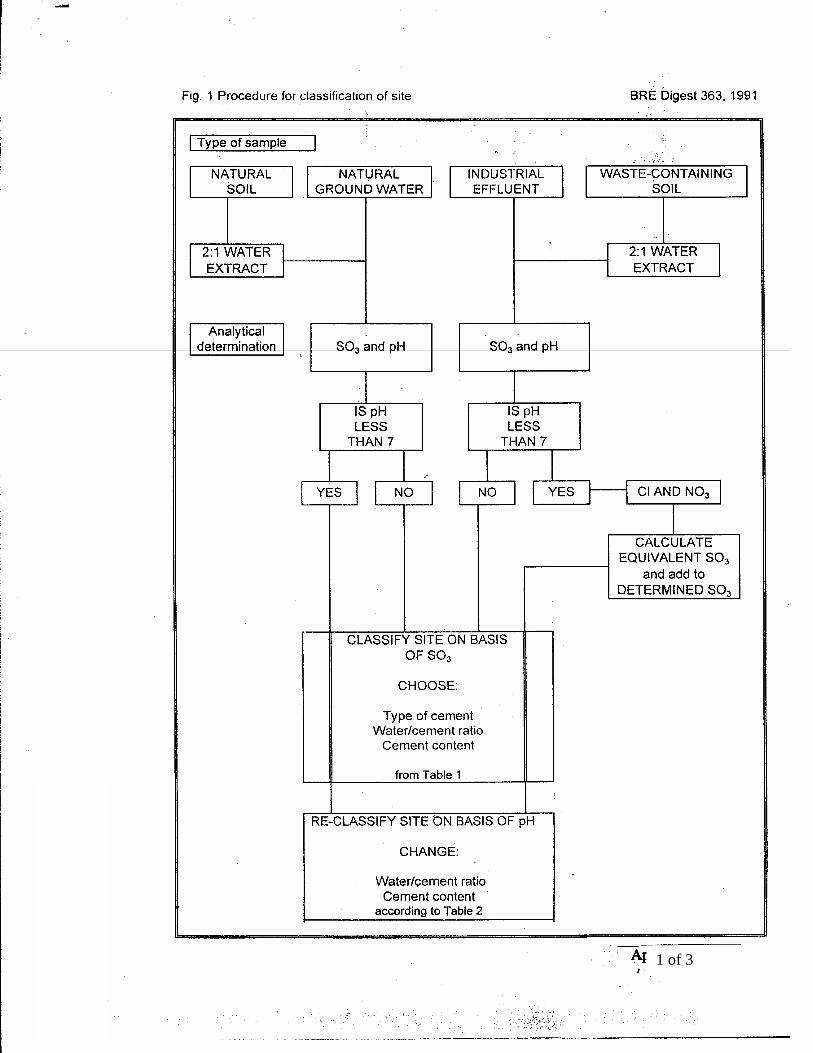
1 of 3
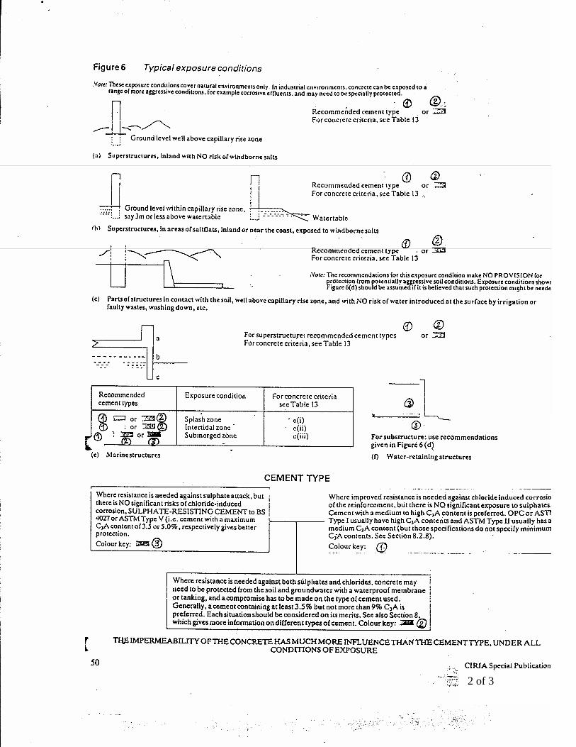
2 of 3
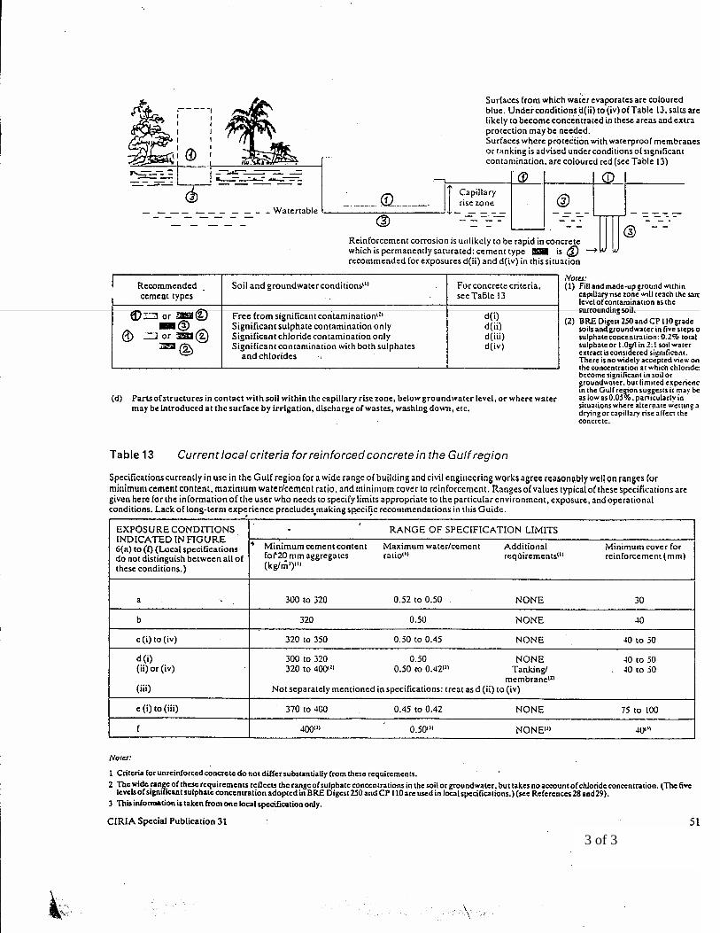
3 of 3
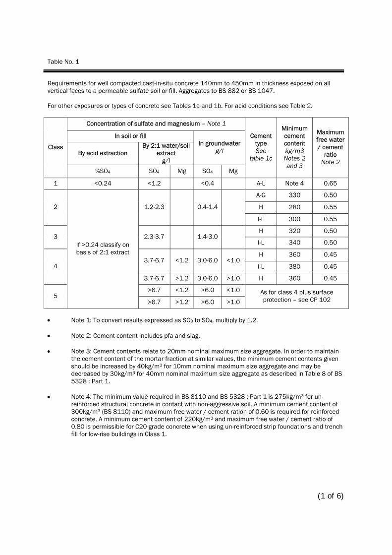
Table No. 1
Requirements for well compacted cast-in-situ concrete 140mm to 450mm in thickness exposed on all vertical faces to a permeable sulfate soil or fill. Aggregates to BS 882 or BS 1047. For other exposures or types of concrete see Tables 1a and 1b. For acid conditions see Table 2.
Concentration of sulfate and magnesium – Note 1
In soil or fill
By acid extraction By 2:1 water/soil
extract g/l
In groundwater g/l Class
%SO4 SO4 Mg SO4 Mg
Cement type See
table 1c
Minimum cement content kg/m3 Notes 2 and 3
Maximum free water / cement
ratio Note 2
1 <0.24 <1.2 <0.4 A-L Note 4 0.65
A-G 330 0.50
H 280 0.55 2 1.2-2.3 0.4-1.4
I-L 300 0.55
H 320 0.50 3 2.3-3.7 1.4-3.0
I-L 340 0.50
H 360 0.45 3.7-6.7 <1.2 3.0-6.0 <1.0
I-L 380 0.45 4
3.7-6.7 >1.2 3.0-6.0 >1.0 H 360 0.45
>6.7 <1.2 >6.0 <1.0 5
If >0.24 classify on basis of 2:1 extract
>6.7 >1.2 >6.0 >1.0
As for class 4 plus surface protection – see CP 102
• Note 1: To convert results expressed as SO3 to SO4, multiply by 1.2. • Note 2: Cement content includes pfa and slag. • Note 3: Cement contents relate to 20mm nominal maximum size aggregate. In order to maintain
the cement content of the mortar fraction at similar values, the minimum cement contents given should be increased by 40kg/m3 for 10mm nominal maximum size aggregate and may be decreased by 30kg/m3 for 40mm nominal maximum size aggregate as described in Table 8 of BS 5328 : Part 1.
• Note 4: The minimum value required in BS 8110 and BS 5328 : Part 1 is 275kg/m3 for un-
reinforced structural concrete in contact with non-aggressive soil. A minimum cement content of 300kg/m3 (BS 8110) and maximum free water / cement ration of 0.60 is required for reinforced concrete. A minimum cement content of 220kg/m3 and maximum free water / cement ratio of 0.80 is permissible for C20 grade concrete when using un-reinforced strip foundations and trench fill for low-rise buildings in Class 1.
(1 of 6)

2 of 6

3 of 6
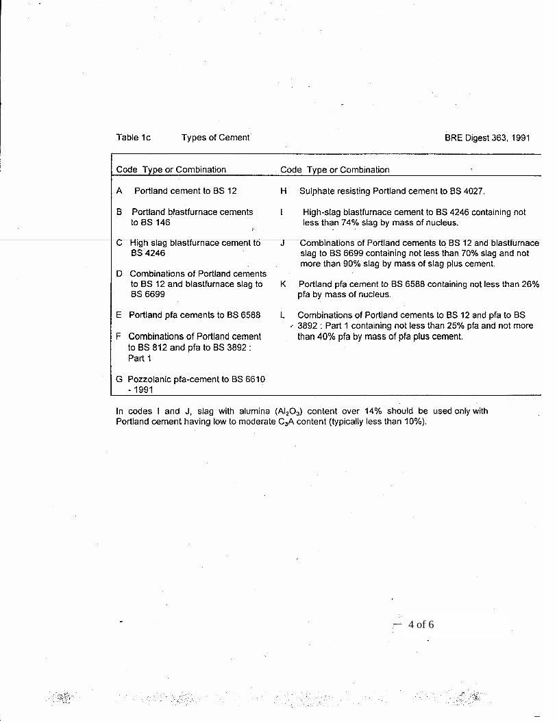
4 of 6
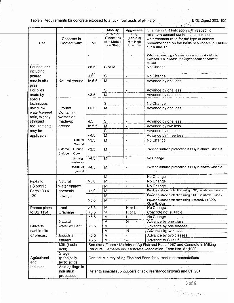
5 of 6
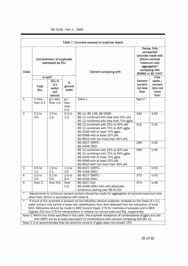
BS 5328 : Part 1 : 1990
Table 7. Concrete exposed to sulphate attack
Concentration of sulphates expressed as SO3
Dense, fully compacted
concrete made with 20mm nominal maximum size aggregates1)
complying with BS882 or BS 1047
In soil2)
Class
Total SO3
SO3 in 2:1
water: soil
extract
In ground water
Cement complying with
Cement content not less
than
Free water / cement ratio not
more than
1 % less than 0.2
g/L less than 1.0
g/L less than 0.3
Table 1 Kg/m3 -
-
BS 12, BS 146, BS 6588 BS 12 combined with less than 25% pfa BS 12 combined with less than 70% ggbs
330 0.50
BS 12 combined with 25% to 40% pfa BS 12 combined with 70% to 90% ggbs BS 4246 with at least 70% ggbs BS 6588 with at least 25% pfa BS 6610 with not more than 40% pfa
310 0.55
BS 4027 (SRPC) BS 4248 (SSC)
280 0.55
2 0.2 to 0.5
1.0 to 1.9
0.3 to 1.2
BS 12 combined with 25% to 40% pfa BS 12 combined with 70% to 90% ggbs BS 4246 with at least 70% ggbs BS 6588 with at least 25% pfa BS 6610 with not more than 40% pfa
380 0.45
3 0.5 to 1.0
1.9 to 3.1
1.2 to 2.5
BS 4027 (SRPC) BS 4248 (SSC)
330 0.50
4 1.0 to 2.0
3.1 to 5.6
2.5 to 5.0
BS 4027 (SRPC) BS 4248 (SSC)
370 0.45
5 Over 2 Over 5.6 Over 5.0
BS 4027 and BS 4248 (SSC) both with adequate protective coating (see BS 8110)
370 0.45
1) Adjustments to minimum cement content should be made for aggregates of nominal maximum size other than 20mm in accordance with table 8.
2) If much of the sulphate is present as low solubility calcium sulphate. Analysis on the basis of a 2:1 water extract may permit a lower site classification than that obtained from the extraction of total SO3. Reference should be made to BRE Current Paper 279 for methods of analysis and to BER Digests 250 and 276 for interpretation in relation to natural soils and fills, respectively.
Note 1: Within the limits specified in this table, the sulphate resistance of combinations of ggbs and pfa with SRPC will be at least equivalent to combinations with cement complying with BS 12.
Note 2: It is recommended that the alumina content of ggbs does not exceed 15%.
(6 of 6)

Vol. III: Bill of Quantities

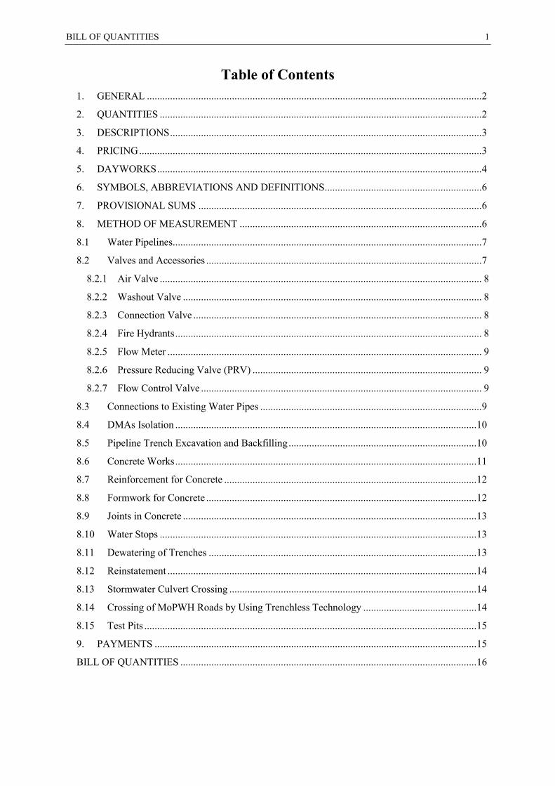
BILL OF QUANTITIES 1
Table of Contents 1. GENERAL .................................................................................................................................. 2
2. QUANTITIES ............................................................................................................................. 2
3. DESCRIPTIONS ......................................................................................................................... 3
4. PRICING ..................................................................................................................................... 3
5. DAYWORKS .............................................................................................................................. 4
6. SYMBOLS, ABBREVIATIONS AND DEFINITIONS............................................................. 6
7. PROVISIONAL SUMS .............................................................................................................. 6
8. METHOD OF MEASUREMENT .............................................................................................. 6
8.1 Water Pipelines........................................................................................................................ 7
8.2 Valves and Accessories ........................................................................................................... 7
8.2.1 Air Valve ............................................................................................................................. 8
8.2.2 Washout Valve .................................................................................................................... 8
8.2.3 Connection Valve ................................................................................................................ 8
8.2.4 Fire Hydrants ....................................................................................................................... 8
8.2.5 Flow Meter .......................................................................................................................... 9
8.2.6 Pressure Reducing Valve (PRV) ......................................................................................... 9
8.2.7 Flow Control Valve ............................................................................................................. 9
8.3 Connections to Existing Water Pipes ...................................................................................... 9
8.4 DMAs Isolation ..................................................................................................................... 10
8.5 Pipeline Trench Excavation and Backfilling ......................................................................... 10
8.6 Concrete Works ..................................................................................................................... 11
8.7 Reinforcement for Concrete .................................................................................................. 12
8.8 Formwork for Concrete ......................................................................................................... 12
8.9 Joints in Concrete .................................................................................................................. 13
8.10 Water Stops ........................................................................................................................... 13
8.11 Dewatering of Trenches ........................................................................................................ 13
8.12 Reinstatement ........................................................................................................................ 14
8.13 Stormwater Culvert Crossing ................................................................................................ 14
8.14 Crossing of MoPWH Roads by Using Trenchless Technology ............................................ 14
8.15 Test Pits ................................................................................................................................. 15
9. PAYMENTS ............................................................................................................................. 15
BILL OF QUANTITIES ................................................................................................................... 16

2 BILL OF QUANTITIES
PREAMBLE TO BILL OF QUANTITIES
1. GENERAL
A. The Bills of Quantities herein, including all notes and instructions, form an integral part of the contract documents. However, the descriptions contained in the Bills of Quantities for each item are not necessarily complete. The Contractor is referred to the Conditions of Contract and other Documents, Specifications and Drawings as well as relevant Standards and Codes of Practice for further information as no claim or variation will be considered on account of the Contractors failure to do so.
B. The Contractor is cautioned to familiarize himself with the full content of other contract documents including the Agreement, General Conditions, Particular Conditions, Tender Drawings and Specifications or any other information that can be reasonably inferred from any of them and all obligations contained in the documents shall be included in the item rates and sums.
C. Drawings, Specifications and Bills of Quantities and all other Contract documents are complementary and if any item is included in any of them, it shall be deemed included in all.
D. The Bills of Quantities are to be read and construed in association with the Drawings, the Specification and this Preamble. Information, which is given on the Drawings and/or in the Specification, is identified by cross-references included in the descriptions of work in the Bills of Quantities.
E. Where work cannot be fully described or where the quantity of work required cannot be accurately determined, it is given as an item or as a Provisional Sum.
F. A price or rate is to be entered against each item in the Bills of Quantities and any item left un-priced will be deemed to be included for elsewhere in the Bills of Quantities and hence the rate for that item will be taken as NIL.
G. The whole cost of complying with the provisions of the Contract shall be included in the Items provided in the priced Bill of Quantities, and where no Items are provided, the cost shall be deemed to be distributed among the rates and prices entered for the related Items of Work.
H. For Ministry of public work and housing (MoPWH) roads, reinstatement shall be in accordance with the last version of the (MoPWH). Regulations, requirements, standards and specifications. This shall be included in the contractor prices.
I. All rates and prices in the Bills of Quantities shall be given in Jordanian Dinars.
J. The Contractor shall use trenchless technology in the construction of the project works specifically in the highway road crossing (if required by Ministry of Public works and Housing MoPWH regulations). The design and specifications for this technology shall be approved by the Engineer and the Employer before use.
2. QUANTITIES
A. The Contractor shall not use these Bills of Quantities as the basis for a construction programme or for the purposes of ordering materials or arranging sub-contracts. The references for these activities shall be the drawings, specifications and approval of the ENGINEER.
B. The whole of the quantities shall be treated as approximate only and are given to provide a common basis for tendering. The basis of payment will be the actual quantities of work ordered and carried out, as measured by the contractor and verified by the Engineer and valued at the rates or prices quoted in the Bills of Quantities payment shall be only for the constituent of meter run with the application of the adjustment item if applicable.
BILL OF QUANTITIES 3
3. DESCRIPTIONS
A. Headings to groups of items in the Bills of Quantities are to be read as part of the descriptions of the items to which the headings apply.
B. Dimensions are stated in descriptions generally in the sequence length, width, or height. Where ambiguity could arise, the dimensions are identified.
4. PRICING
A. The prices shall be comprehensive and must include for complying in all respects with the Instructions to Tenderers, Conditions of Contract, Specifications and Drawings and for all matters and things necessary for the proper construction, completion, and maintenance of the whole of the Works.
B. No claims for additional payment will be allowed for any error or misunderstanding by the Contractor of the work involved.
C. The rates and sums inserted in the Bill of Quantities are deemed to include for the following:-
a) Mobilization and demobilization. b) labour and all costs in connection therewith, c) materials, products, goods and all costs in connection therewith, d) overhead charges, G&A and profit, e) Contractor's equipment, including but not limited to construction plant, scaffolding, tools,
vehicles and the like, and all costs in connection therewith, f) assembling, fitting and fixing materials, products and goods in position, g) any method of fixing, fixing to any nature of base or background including preparation and
providing fixing materials, h) breaking down for transport and installation and subsequent re-assembly of composite
items manufactured off site, i) waste of materials, bulking, shrinkage, working space and overlaps, j) square, raking and curved cutting, k) work at any location or height, l) work in small, isolated quantities, m) protection of all work, n) protection of all existing structures, utilities, site improvements, trees and vegetation,
features, pavements and other facilities on and adjacent to the site, which are to remain upon completion of the work,
o) all other enabling tasks, associated and subsidiary components and items of work, which are indicated or reasonably inferred from the Drawings and/or Specification, and necessary to perform and complete the work described.
p) water, lighting and power for the works, q) temporary roads, hard standings, crossings and the like, r) temporary fencing, hoardings, screens, fans, foot- ways, guardrails, gantries and the like, s) any temporary works necessary to maintain traffic. t) giving notices and making applications, including the payment of fees and charges in
connection therewith, u) taking measures to ensure the safety, health and welfare of work people, v) compliance with traffic regulations, w) maintenance of public and private roads, services and adjoining property,
4 BILL OF QUANTITIES
x) land required for tips and stockpiles including all costs for obtaining any necessary licenses and approvals.
y) control of noise and pollution, prevention of fire and compliance with all other statutory and general obligations,
z) removing rubbish, protective casings and coverings and cleaning the works on completion, aa) drying the works, bb) testing and commissioning of service installations including providing water, fuel, and the
like, cc) samples of materials required for testing and testing of materials, including providing
equipment for testing, dd) preparation and supply of workshop drawings, as-built record drawings, operation and
maintenance manuals and the like, ee) preparation and submittal of reports, records, work programmes, certificates, notices,
proposals, designs, details, calculations and other information and data required by the Specifications,
ff) working alongside and liaising with other Contractors working on the same site. gg) all other requirements services, provisions, liabilities and obligations contained in the
General Requirements and Conditions of Contract. hh) maintaining, adapting, clearing away and making good of temporary works. ii) Topographic survey for the excavation and successful completion of works. jj) Safety and health provision and measurement. kk) Coordination with authorities and stakeholders. ll) Pre and post site assessment. mm) reinstatement of road surface.
D. Except where items are included in the Bills of Quantities and are priced separately by the Contractor therein, provision of the following are deemed to be included with all work:
a) site administration and security, b) insurances, c) bonds and guarantees, d) approvals and permitting, e) transportation, material handling and storage import and custom duties and fees.
E. Where fix only items are specified, the rate shall be deemed to include for selecting, cleaning, taking delivery, storing and installation of goods or materials in the works where appropriate.
F. Any arithmetic errors in computation or summation will be corrected by the Employer as follows:
a) where there is a discrepancy between amounts in figures and in words, the amount in words will govern; and
b) where there is a discrepancy between the unit rate and the total amount derived from the multiplication of the unit price and the quantity, the unit rate as quoted will govern, unless in the opinion of the Employer, there is an obviously gross misplacement of the decimal point in the unit price, in which event the total amount as quoted will govern and the unit rate will be corrected.
5. DAYWORKS
A. GENERAL
BILL OF QUANTITIES 5
a) The rates inserted in the Schedule of Dayworks shall be deemed to be the rates used by the Contractor in making up rates for works in all sections of the Bills of Quantities.
b) The rate for any labour or Contractor’s equipment not identified in the Bills of Quantities shall be fixed by the Engineer based upon what, in the Engineers opinion, is the nearest similar item appearing in the Bills of Quantities or, where in the Engineer’s opinion, there is no similar item, at a rate analogous to rates contained in the Bills of Quantities, and at a rate considered to be fair and reasonable by the Engineer.
B. LABOUR
a) In calculating payments due to the Contractor for the execution of daywork, the hours for labour will be reckoned from the time of arrival of the labour at the job site of the daywork to the time of return to the original place of work, but excluding meal breaks and rest periods. Only the time of classes of labour directly carrying out work ordered by the Engineer, and which they are competent to perform, will be measured. The time of gangers (charge hands) actually working with the gangs will be measured but not the time of foremen or other supervisory personnel.
b) The rates inserted in the Bills of Quantities shall be deemed to cover all of the Contractors obligations and costs in providing and maintaining such labour at the place of work including but not limited to wages, payments for conditions and skill, bonus, travelling and subsistence allowances and expenses, administration, provision of welfare facilities, personal protective equipment (PPE), small tools, overheads, profit and all incidental expenses.
C. EQUIPMENT
a) The Contractor shall be entitled to payment in respect of Contractor's Equipment already on Site and employed on daywork at the basic rental rates entered by him in the Bills of Quantities. The said rates shall be deemed to include, but not be limited to: i) complete allowance for depreciation; ii) interest, indemnity and insurance; iii) repairs, maintenance; iv) supplies, fuel, lubricants, and other consumables; v) general obligations, liabilities and risks involved in the execution of the works as set
out in or reasonably inferred from the Contract; vi) and all overheads, profit and administrative costs related to the use of such equipment.
The said rates shall also include the cost of drivers, operators and assistants. b) In calculating the payment due to the Contractor for the equipment employed on daywork,
only the actual number of working hours will be eligible for payment. c) Standing time shall be measured for Contractor's equipment where the nature of the
daywork requires intermittent working, but shall not include standing time which occurs before the daywork commences or after the daywork is completed. Standing time in excess of eight consecutive hours will only be paid if the standing time has the prior consent of the Engineer. All standing time shall be paid for at one half of the relevant rates inserted in the Bills of Quantities or prices fixed by the Engineer.
d) No payment shall be made for Contractor’s plant and equipment which is not operating because it is broken down or undergoing repair, maintenance or overhaul.
6 BILL OF QUANTITIES
6. SYMBOLS, ABBREVIATIONS AND DEFINITIONS
A. The following notations are used in the Bills of Quantities:-
Unit Abbreviation Unit Abbreviation
Centimetre Milimetre
cm mm
Diameter Lump Sum
Dia. LS
Linear metre M Nominal Diameter Outside Diameter
DN, Ø OD
Square metre M2 Nominal Pressure PN
Cubic metre M3 Quantity Qty.
Percentage % Ductile Iron DI
Number No. Provisional Sum PS
Polyethylene PE
Drawings Drg.
Bills of Quantities BOQ B. The following definitions apply to all work:
a) 'horizontal' means level or sloping work not exceeding 15 degrees from the horizontal, b) 'sloping' means sloping work exceeding 15 degrees but not exceeding 80 degrees from the
horizontal, c) 'vertical' means work exceeding 80 degrees from the horizontal, d) 'curved' means curved in any direction or in more than one direction and to any radius or
radii, and includes curved work to domes, vaults and the like, e) 'extra over' means that the work so described involves extra cost over the basic work in
which it occurs. No deduction of the quantity of basic work is made for the extra over work. f) ‘Rock’ is defined as all materials that, in the opinion of the Engineer, require blasting, or
the use of metal wedges and sledgehammers, or the use of compressed air drilling for their removal, and that cannot be extracted by ripping with a tractor of at least 150 brake hp with a single, rear-mounted, heavy-duty ripper.
7. PROVISIONAL SUMS
A. Provisional items are included for diversion works of existing utilities, supply of goods, materials, or services, or for contingencies.
B. Provisional Sums included and so designated in the Bill of Quantities shall be expended in whole or in part at the direction and discretion of the Engineer in accordance with Sub-Clause 13.5 and Clause 13.6 of the General Conditions.
8. METHOD OF MEASUREMENT
A. Works shall be measured net as fixed in position in accordance with the rules contained in this Method of Measurement or except where otherwise stated in a measurement rule applicable to the work.
B. Dimensions used in calculating quantities are taken to the nearest 10 mm (i.e. 5 mm and over is regarded as 10 mm and less than 5 mm is disregarded).
BILL OF QUANTITIES 7
C. Unless the term meter, used in this Method of Measurement, is preceded by the words square or cubic it is deemed to be linear.
D. The rules contained in this Method of Measurement apply equally to both proposed and executed works.
8.1 Water Pipelines
A. Each kind of pipe is given separately.
B. Diameters stated are nominal diameters DN in millimetres for DI water pipelines and outside diameter OD for PE water pipelines.
C. Water pipes are given in linear meters for each diameter including all fittings.
D. No allowance is made for cut ends and waste.
E. Work is deemed to include but not limiting to:-
a) Pipeline trench excavation at any depth and width and backfilling. b) supply and installation of pipes, joints, fittings, specials and materials as specified and
shown in the drawings, c) all fittings, and accessories shall be included in the pipe length price, d) executing the works at any location, e) cutting, machining, chamfering, etc. of pipes, f) cleaning pipelines, disinfection and bacteriological testing g) rectifying any damage to shop coatings and any site coatings as specified, h) lubricating and jointing agents used for assembling the pipe sections, i) laboratory and field testing as per specification, j) Painting, lining, coating and ancillary works and materials as specified. k) hydrostatic testing and commissioning of the system including all required personnel,
materials, temporary works, instrumentation, fuel, water, and the like, l) labour and equipment used in all above, m) Temporary or permanent removal and/or relocation of an existing Utility (electricity,
telecommunication cables and existing water pipes) as per specification. n) Trench bedding, thrust block and surface reinstatement.
8.2 Valves and Accessories
A. Each type of valve is given separately.
B. Each type of valve is classified according to diameter and class.
C. Valve and accessories are enumerated.
D. The rate for valve and accessories are deemed to include but not limiting to:
a) supply and installation of valves as specified, b) supply of other valves, pressure gauge and accessories as per drawing c) valve chamber (can be a surface box for valve upto DN 150 mm), concrete, excavation
shoring, and backfilling, leveling, compaction reinstatement, blinding and reinforcing steel, d) lowering into trench and chambers and installation, e) over-excavation for concrete supports,

8 BILL OF QUANTITIES
f) concrete supports and thrust blocks. Concrete works shall include all items required for Concrete Works,
g) bolts, nuts, gaskets and ancillary works including materials required, h) drilling and fixing the pipe threaded outlet for threaded connection, i) ancillary works and materials required and all labour and equipment used, j) painting, lining and coating as specified, k) shoring, leveling and compaction, l) reinstatement
8.2.1 Air Valve
A. The rates for air valve are deemed to include but not limiting to the following:
a) supply of associated isolating gate/sluice valves, b) supply of air valve, c) installation and fixing, d) valve chamber complete with cover and frame and concrete works, e) fittings, dismantling pieces, flanges and puddle flanges, and vent pipes, f) ladder or steps g) testing
8.2.2 Washout Valve
A. The rates for washout valve are deemed to include but not limiting to the following:
a) Valve, chamber complete with cover and frame and concrete works, b) fittings, dismantling pieces, flanges and puddle flanges, c) installation and fixing, d) ladder or steps e) testing. f) Gate/Butterfly valves, g) Washout collection manhole,
8.2.3 Connection Valve
A. The rates for isolation valve are deemed to include but not limiting to the following:
a) supply of associated isolating gate/butterfly valves, b) valve chamber complete with cover and frame and concrete works, c) fittings, dismantling pieces, flanges and puddle flanges, d) installation and fixing, e) ladder or steps. f) testing
8.2.4 Fire Hydrants
A. The rates for fire hydrants are deemed to include but not limiting to the following:-
a) supply and installation of fire hydrant, gate valve and pipe from main line to fire hydrant as per the Design Drawings,
BILL OF QUANTITIES 9
8.2.5 Flow Meter
A. The rates for flow meters are deemed to include but not limiting to the following:
a. Supply of flow meter, b. installation and fixing, c. valve including pressure gauge, chamber complete with cover, concrete works, d. fittings, dismantling pieces, flanges and puddle flanges, e. ladder or steps. f. Testing
8.2.6 Pressure Reducing Valve (PRV)
A. The rates for PRVs are deemed to include but not limiting to the following:
a) supply PRV, b) supply of associated isolating gate/butterfly valves, c) supply of air valve, pressure gauge d) installation and fixing, e) valve chamber complete with cover, concrete works, f) fittings, dismantling pieces, flanges and puddle flanges, strainer, g) ladder or steps. h) Testing
8.2.7 Flow Control Valve
A. The rates for the flow control valves are deemed to include but not limiting to the following:-
a. Supply of flow control valve (Butterfly), b. installation and fixing, c. valve chamber complete with cover, concrete works, d. fittings, valves, dismantling pieces, flanges and puddle flanges, e. ladder or steps. f. Testing
8.3 Connections to Existing Water Pipes
A. Each type of connection is given separately.
B. Each type of connection is classified by the diameter of the largest pipe of the connection. No classification is made regarding the type of the material of the existing pipe.
C. Connections are enumerated.
D. The rates for connections to existing pipe are deemed to include but not limiting to the following:-
a) Supply of material specified and shown on drawings to suit the existing pipe, b) Excavation and backfilling, c) Thrust and support blocks, d) Installation and fixing,
10 BILL OF QUANTITIES
e) Ancillary works and materials required and all labor and equipment used, f) Painting, lining, coating as specified.
8.4 DMAs Isolation
A. DMAs isolation is given separately and as a lump sum price for the complete working system and as shown in the Design Drawings.
B. The DMAs isolation work include but not limiting to:
a. supply of material specified and as shown in Drawings, Volume Four, b. excavation and backfilling, c. installation and fixing, d. ancillary works and materials required and all labour and equipment used, e. concrete work, f. reinforcement of steel works g. building in ends of pipes including cutting pipes and sealing, h. Installing of required temporary isolation valves on all existing water pipelines along the
boundary of each DMA in order to have a fully isolated DMA. i. Testing the isolation of each DMA during the water supply period. j. After checking the isolation of each DMA, the installed temporary isolation valves should
be replaced by end plugs for diameters less than 400mm, for diameters equal and more than 400 mm the installed isolation valve should be kept and closed.
8.5 Pipeline Trench Excavation and Backfilling
A. Pipeline trench excavation and backfilling are not measured separately and shall be deemed included in gravity water pipelines price.
B. Pipeline trench excavations and backfilling are deemed to include but not limiting to:-
a) excavating in any material encountered, b) excavating to any depth and width shown on drawings, c) locating and excavating around existing services and protection of those services during the
excavation including all necessary temporary support, d) excavating curved on plan, e) excavation by hand where mechanical excavation is not permitted or feasible, f) removal of existing utilities, g) provision of access at all times to the properties affected by the work, h) allowance for working space, i) segregation of the various classes of excavated soil and stock piling as may be directed by
the Engineer, j) excavating below water table, k) keeping excavations free from water, l) levelling, ramming, trimming and grading bottoms and trimming sides and bottoms of
excavation, m) supporting or, where permitted, battering the sides of excavations, n) planking, shoring and strutting, o) breaking up surface layers (asphalt, concrete, gravel) irrespective of thickness,
BILL OF QUANTITIES 11
p) disposal of surplus excavated material including depositing and consolidating where directed on Site or removing from Site and depositing at a tip to be provided and paid for by the Contractor,
q) backfilling over-excavations, r) preparing surfaces to receive filling, s) replacement of the unsuitable materials at the excavation level with approved granular
materials, t) backfilling and compaction of pipe zone backfill (bedding and embedment), u) supply and installation of warning tapes, v) backfilling and compaction of trench zone backfill, w) backfilling and compaction of final backfill, x) using material arising from excavations including selecting and treating or using imported
filling material, y) labour and equipment used in excavation and backfilling, including multiple handling of
excavation, and transporting about the Site.
8.6 Concrete Works
A. Concrete for chambers and blinding is not measured separately. This work is deemed to be included and priced within the rates of valves and pipeline installation, based on the design Drawings.
B. Concrete for pipe surround and encasement is given separately stating the grade, kind of cement and whether plain or reinforced.
C. Concrete for pipe, valves and fittings surround is given in cubic metres measured net except that deductions are not made for the following:
a) reinforcement, b) steel sections of area not exceeding 0.05M2, c) voids not exceeding 0.05M3 in volume.
D. Work is deemed to include but not limiting to:
a) designing mixes, (including all tests and quality control procedures), b) any method of pouring, placing, compacting and curing, c) pouring on or against earth or unblended hardcore, d) any thickness, cross-sectional area or number of members, e) horizontal, sloping, vertical and curved work, f) placing or finishing to falls and cross falls, g) forming of boxouts, holes, pockets, rebates etc., h) building in or building through of pipework, i) basic finish as struck from formwork and tamped worked finish, j) extra width of concrete or formwork to edges of blinding beds, k) precast units including hauling and placing, l) temporary formwork or other form of temporary support to all surfaces, including design,
construction, supports, fixing, striking, removing, re-propping and all formwork requirements mentioned in Chapter 03100 – Concrete Formwork of the Technical Specifications.
m) reinforcement content of any percentage of the volume of concrete,
12 BILL OF QUANTITIES
n) day joints (construction joints), contraction joints and joints required in the forming of bays including formwork and treatment of reinforcement crossing the joint, column and wall kickers and construction joints,
o) expansion joints, p) damp proofing membrane and coatings to foundations and manholes below ground level, q) all labours on concrete including working around pipes or cables, cutting channels, chases,
mortices, pockets and holes and including subsequent grouting or filling and making good.
8.7 Reinforcement for Concrete
A. Bar reinforcement is not measured separately. This work is included and priced within the concrete works, based on the Design Drawings.
B. Work is deemed to include include but not limiting to:
a) preparing schedules for bar bending, b) fixing bars in any position and in any member , c) fixing bars horizontally, vertically and sloping, d) any diameter, section and length of bars, e) forming straight, bent and curved bars and links, f) cutting, lapping and jointing (including special joints), g) hooks, tying wire, spacers, chairs and the like, h) the weight of surface treatments and rolling margin, i) Tests and quality control procedures.
8.8 Formwork for Concrete
A. Temporary formwork to produce basic and plain (fair faced) finish if any, is deemed to be included within the price of concreting. Permanent formwork and concrete filler block which is designed to remain in position is deemed to be included within the price of concreting.
B. Basic tamped finish to surfaces of concrete is not measured, it is deemed to be included within the price of concreting.
C. Work is deemed to include:
a) basic finish as struck from formwork and tamped worked finish, b) extra width of concrete or formwork to edges of blinding beds, c) formwork or other form of temporary support to top of sloping upper surfaces of blinding
beds, d) design and construction, e) supports, battens, struts, bracings, wedging and fixings, easing, striking and removing, f) overlaps and passings at angles, g) repropping, if approved, h) supporting concrete of any thickness and at any height to soffit, i) any width or height of formwork, j) any number of concrete members and any number of separate surfaces in each member, k) any profile of beam, column, upstand, projection or recess including formwork to the ends
of such,
BILL OF QUANTITIES 13
l) all cutting, splayed edges and the like, m) forming grooves, chamfers, ribs and the like including providing battens and 'boxings, n) forming mortices and pockets and forming holes for pipes, ducts, cables and the like, o) adaptation to accommodate projecting pipes, reinforcing bars and the like, p) access opening and temporary openings, q) mould oil, release agents and surface retreads, r) re-using formwork or removing from site formwork not to be re-used, fixation of any
embedded items (steel plates, inserts. .etc ) s) day joints (construction joints) and joints required in the forming of bays including
formwork and treatment of reinforcement crossing the joint, t) all labours on concrete including working around pipes or cables, cutting channels, chases
mortices, pockets and holes and including subsequent grouting or filling and making good.
8.9 Joints in Concrete
A. Construction, contraction and expansion joints are not measured separately. This work is deemed to be included and priced within the concrete works, based on the Design Drawings. Work is deemed to include:
a) sheet material filler, b) formwork, c) horizontal, sloping and vertical work, any width or depth of joint, d) joint sealant, including preparation of surfaces, cleaners, primers, sealers backing strips and
bond breakers for all horizontal, sloping, vertical and curved work.
8.10 Water Stops
A. Water stops are not measured separately. This work is deemed to be included and priced within the concrete works, based on the Design Drawings.
B. Work is deemed to include:
a) horizontal, vertical, sloping and curved work, b) ends, angles and intersections, irrespective of whether standard, welded or purpose made.
8.11 Dewatering of Trenches
A. Dewatering of trenches is not measured separately.
B. Dewatering of trenches is deemed to be included in the rate for gravity water pipelines work.
C. Whenever ground water is encountered, all trenches are to be dewatered prior to installation of pipe or construction of valve chambers.
D. Work is deemed to include:
a) keeping excavations free from water during installation of pipe and until backfilling reaches above groundwater table,
b) disposal of groundwater to locations approved by the Engineer,
14 BILL OF QUANTITIES
8.12 Reinstatement
A. Trench reinstatement is not measured separately. The cost of reinstatement is deemed to be included within the price of gravity water pipelines work.
B. Thickness, dimensions, types and details are stated in descriptions and on Drawings where necessary to identify the work.
C. Work for reinstatement are deemed to include:
a) setting out, b) extra work involved in patterned work and work in multi-colours, c) work of any width, height and girth, d) special and non-standard tiles and slabs, e) slabs and tiling laid to falls and cross falls (where the incline from horizontal does not
exceed 15 degrees), f) sand levelling bed, g) cement-sand screeds, h) adhesive and fixing materials and/or devices, i) bedding and backing mortars, all cutting including circular cutting, internal and external
angles, intersections, joints, division strips and anti-slip nosings, j) jointing, grouting, cleaning, sealing, grinding and polishing including working overhand
and working over and around obstructions, k) shop drawings, samples and test results, l) protection, m) compaction & testing, n) Prime coats, o) Base course layers as specified and shown on drawings, and p) Gabion layers as specified and shown on drawings. q) Binder and wearing cover layers as specified and shown in drawings, Standard Details).
8.13 Stormwater Culvert Crossing
A. Stormwater culvert crossing is not measured separately and it is deemed to include in the rate for gravity water pipelines work.
B. Work deemed to include:
a) Cracking and reconstructing the stormwater culvert with the same existing level and the same existing situation.
b) Do all necessary to complete the work
8.14 Crossing of MoPWH Roads by Using Trenchless Technology
A. Using trenchless technology in the construction of the project works specifically in the highway road crossing (if required by MoPWH regulations) is measured separately and it is deemed to include but not limiting to:
a) Supply of material, b) Excavation and backfilling, c) Thrust and support blocks, d) Installation and fixing,
BILL OF QUANTITIES 15
e) Ancillary works and materials required and all labor and equipment used,
8.15 Test Pits
A. Test pits are measured separately which will be conducted every 500m along the new strengthening pipelines
9. PAYMENTS
A. No partial payment shall be made, 100% of the estimated values of the metre run less retention shall be paid after completion of all tidying up and surface reinstatement have been carried out.

16 BILL OF QUANTITIES
BILL OF QUANTITIES
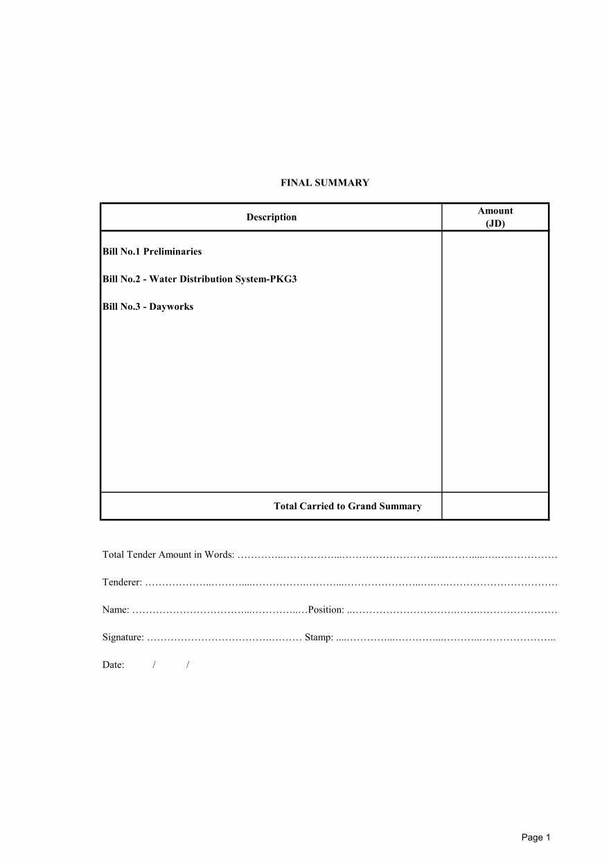
Bill No.1 Preliminaries
Bill No.2 - Water Distribution System-PKG3
Bill No.3 - Dayworks
Total Tender Amount in Words: …………..……………...………………………...……….....….….……………
Tenderer: ………………..………....…………….………...…………………..….….……………………………..
Name: ……………………………...…………..…Position: ..………………………….…….…………………….
Signature: ……………………………….……… Stamp: ....…………...…………...………..…………………..
Date: / /
Total Carried to Grand Summary
FINAL SUMMARY
Description Amount(JD)
Page 1
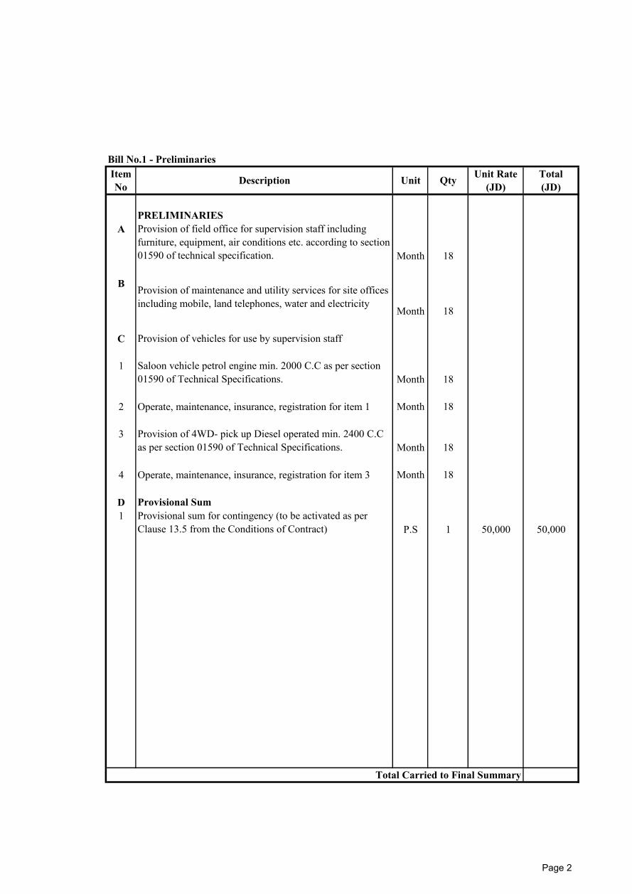
PRELIMINARIESA
Month 18
B
Month 18
C Provision of vehicles for use by supervision staff
1Month 18
2 Operate, maintenance, insurance, registration for item 1 Month 18
3Month 18
4 Operate, maintenance, insurance, registration for item 3 Month 18
D Provisional Sum1
P.S 1 50,000 50,000
Bill No.1 - PreliminariesItemNo Description Unit Qty Unit Rate
(JD)Total(JD)
Provision of field office for supervision staff includingfurniture, equipment, air conditions etc. according to section01590 of technical specification.
Provision of maintenance and utility services for site officesincluding mobile, land telephones, water and electricity
Saloon vehicle petrol engine min. 2000 C.C as per section01590 of Technical Specifications.
Provision of 4WD- pick up Diesel operated min. 2400 C.Cas per section 01590 of Technical Specifications.
Total Carried to Final Summary
Provisional sum for contingency (to be activated as perClause 13.5 from the Conditions of Contract)
Page 2
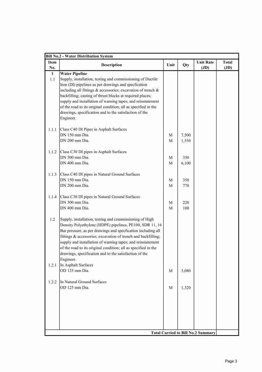
1 Water Pipeline 1.1
1.1.1 Class C40 DI Pipes in Asphalt SurfacesDN 150 mm Dia. M 7,500DN 200 mm Dia. M 1,550
1.1.2 Class C30 DI pipes in Asphalt SurfacesDN 300 mm Dia. M 350DN 400 mm Dia. M 6,100
1.1.3 Class C40 DI pipes in Natural Ground SurfacesDN 150 mm Dia. M 350DN 200 mm Dia. M 770
1.1.4 Class C30 DI pipes in Natural Ground SurfacesDN 300 mm Dia. M 220DN 400 mm Dia. M 100
1.2
1.2.1 In Asphalt SurfacesOD 125 mm Dia. M 3,080
1.2.2 In Natural Ground SurfacesOD 125 mm Dia. M 1,320
Bill No.2 - Water Distribution SystemItemNo. Description Unit Qty Unit Rate
(JD)Total (JD)
Total Carried to Bill No.2 Summary
Supply, installation, testing and commissioning of DuctileIron (DI) pipelines as per drawings and specficationincluding all fittings & accessories; excavation of trench &backfilling; casting of thrust blocks at required places;supply and installation of warning tapes; and reinstatementof the road to its original condition; all as specified in thedrawings, specification and to the satisfaction of theEngineer.
Supply, installation, testing and commissioning of HighDensity Polyethylene (HDPE) pipelines, PE100, SDR 11, 16Bar pressure, as per drawings and specfication including allfittings & accessories; excavation of trench and backfilling;supply and installation of warning tapes; and reinstatementof the road to its original condition; all as specified in thedrawings, specification and to the satisfaction of theEngineer.
Page 3
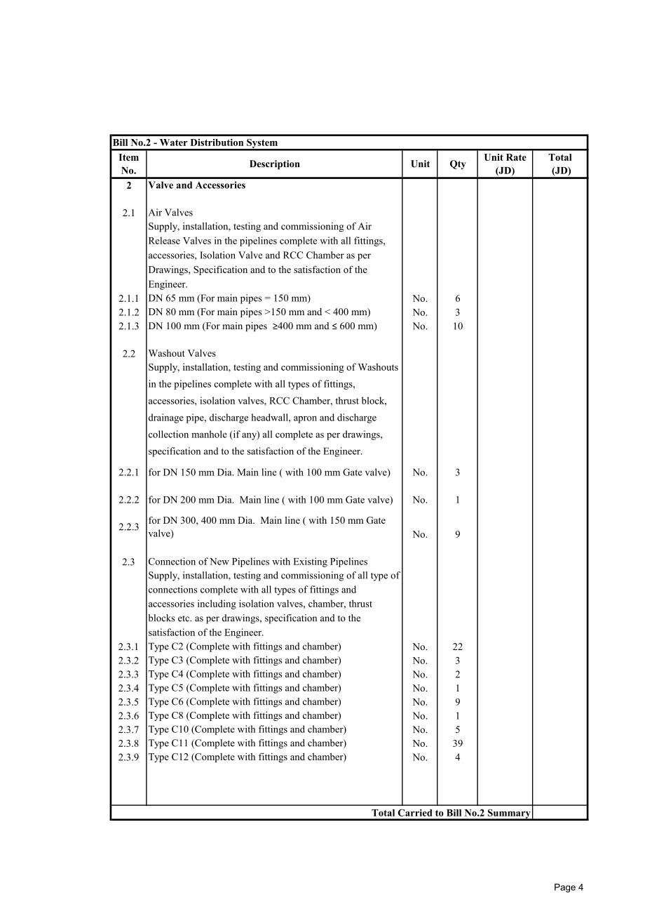
2 Valve and Accessories
2.1 Air Valves
2.1.1 DN 65 mm (For main pipes = 150 mm) No. 62.1.2 DN 80 mm (For main pipes >150 mm and < 400 mm) No. 32.1.3 DN 100 mm (For main pipes ≥400 mm and ≤ 600 mm) No. 10
2.2 Washout Valves
2.2.1 for DN 150 mm Dia. Main line ( with 100 mm Gate valve) No. 3
2.2.2 for DN 200 mm Dia. Main line ( with 100 mm Gate valve) No. 1
No. 9
2.3 Connection of New Pipelines with Existing Pipelines
2.3.1 Type C2 (Complete with fittings and chamber) No. 222.3.2 Type C3 (Complete with fittings and chamber) No. 32.3.3 Type C4 (Complete with fittings and chamber) No. 22.3.4 Type C5 (Complete with fittings and chamber) No. 12.3.5 Type C6 (Complete with fittings and chamber) No. 92.3.6 Type C8 (Complete with fittings and chamber) No. 12.3.7 Type C10 (Complete with fittings and chamber) No. 52.3.8 Type C11 (Complete with fittings and chamber) No. 392.3.9 Type C12 (Complete with fittings and chamber) No. 4
2.2.3
Bill No.2 - Water Distribution SystemItemNo. Description Unit Qty Unit Rate
(JD)Total (JD)
Total Carried to Bill No.2 Summary
Supply, installation, testing and commissioning of AirRelease Valves in the pipelines complete with all fittings,accessories, Isolation Valve and RCC Chamber as perDrawings, Specification and to the satisfaction of theEngineer.
Supply, installation, testing and commissioning of Washoutsin the pipelines complete with all types of fittings,accessories, isolation valves, RCC Chamber, thrust block,drainage pipe, discharge headwall, apron and dischargecollection manhole (if any) all complete as per drawings,specification and to the satisfaction of the Engineer.
Supply, installation, testing and commissioning of all type ofconnections complete with all types of fittings andaccessories including isolation valves, chamber, thrustblocks etc. as per drawings, specification and to thesatisfaction of the Engineer.
for DN 300, 400 mm Dia. Main line ( with 150 mm Gatevalve)
Page 4
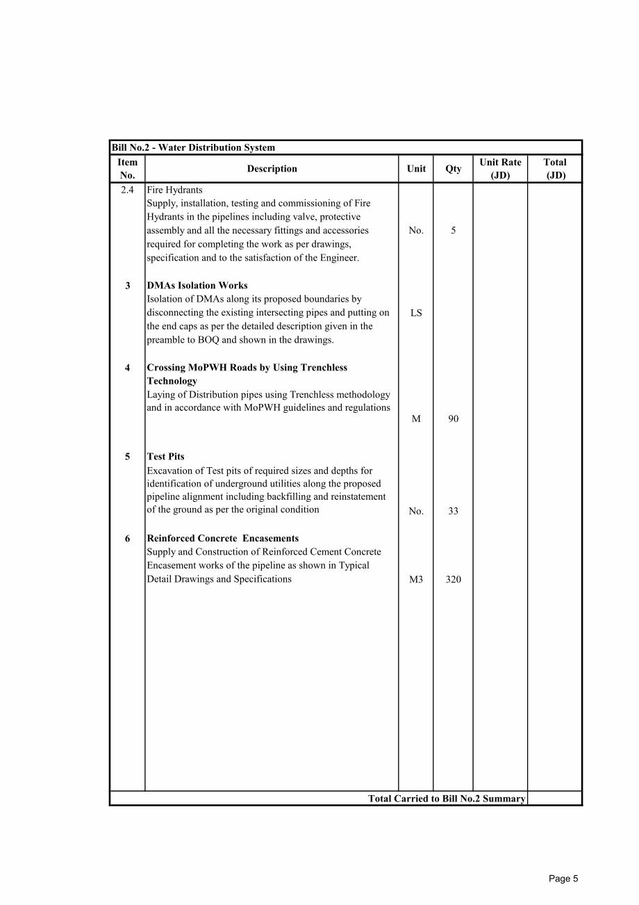
2.4 Fire Hydrants
3 DMAs Isolation Works
LS
4
M 90
5 Test Pits
No. 33
6 Reinforced Concrete Encasements
M3 320
No. 5
Bill No.2 - Water Distribution SystemItemNo. Description Unit Qty Unit Rate
(JD)Total (JD)
Crossing MoPWH Roads by Using TrenchlessTechnology
Isolation of DMAs along its proposed boundaries bydisconnecting the existing intersecting pipes and putting onthe end caps as per the detailed description given in thepreamble to BOQ and shown in the drawings.
Excavation of Test pits of required sizes and depths foridentification of underground utilities along the proposedpipeline alignment including backfilling and reinstatementof the ground as per the original condition
Supply and Construction of Reinforced Cement ConcreteEncasement works of the pipeline as shown in TypicalDetail Drawings and Specifications
Total Carried to Bill No.2 Summary
Laying of Distribution pipes using Trenchless methodologyand in accordance with MoPWH guidelines and regulations
Supply, installation, testing and commissioning of FireHydrants in the pipelines including valve, protectiveassembly and all the necessary fittings and accessoriesrequired for completing the work as per drawings,specification and to the satisfaction of the Engineer.
Page 5
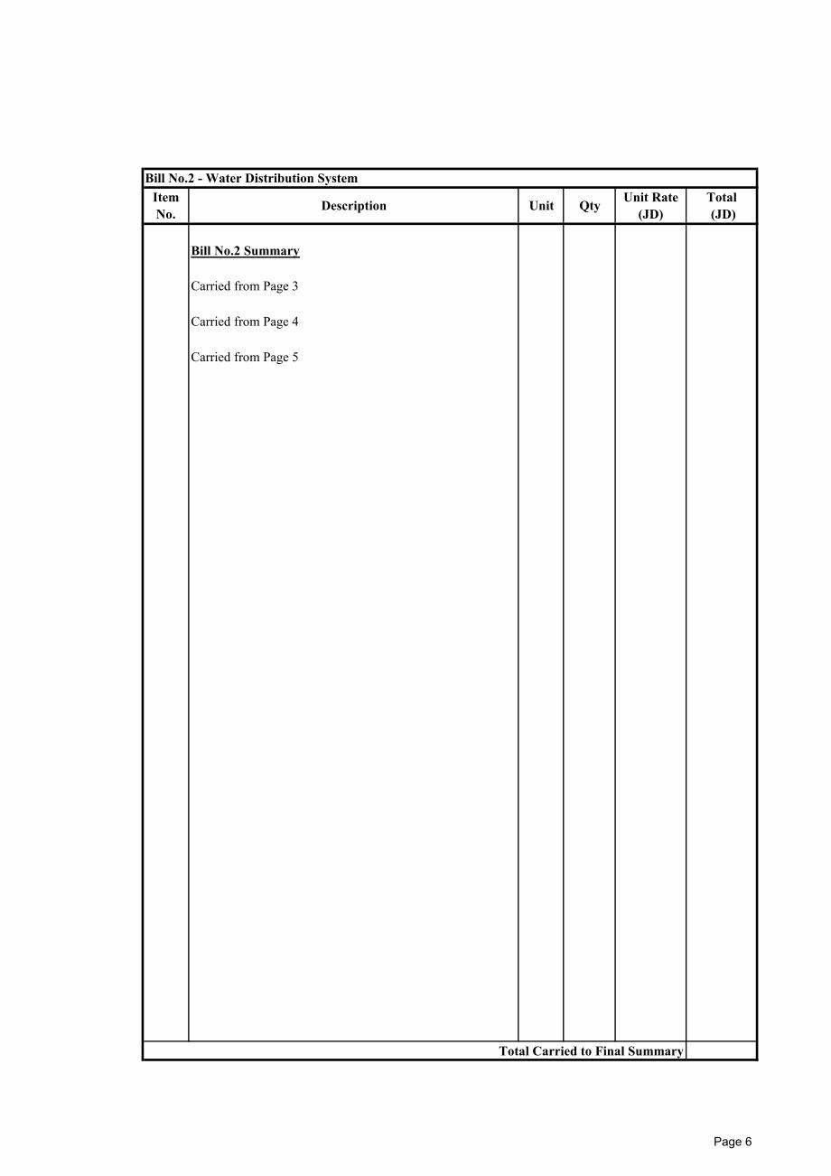
Bill No.2 Summary
Carried from Page 3
Carried from Page 4
Carried from Page 5
Unit Rate(JD)
Total Carried to Final Summary
Total (JD)
Bill No.2 - Water Distribution SystemItemNo. Description Unit Qty
Page 6
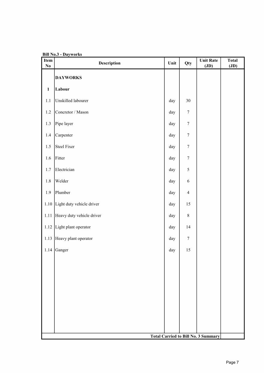
Bill No.3 - Dayworks
DAYWORKS
1 Labour
1.1 Unskilled labourer day 30
1.2 Concretor / Mason day 7
1.3 Pipe layer day 7
1.4 Carpenter day 7
1.5 Steel Fixer day 7
1.6 Fitter day 7
1.7 Electrician day 5
1.8 Welder day 6
1.9 Plumber day 4
1.10 Light duty vehicle driver day 15
1.11 Heavy duty vehicle driver day 8
1.12 Light plant operator day 14
1.13 Heavy plant operator day 7
1.14 Ganger day 15
Total Carried to Bill No. 3 Summary
Total (JD)
ItemNo Description Unit Qty Unit Rate
(JD)
Page 7

Bill No.3 - Dayworks
2 Equipment
2.1 Trench compactor day 8
2.2 Wheel mounted shovel/loader 1 m³ capacity day 8
2.3 Excavator day 5
2.4 Compressor 500- 6000 litres capacity with small tools day 13
2.5 Concrete mixer 0.50 m3 capacity. day 4
2.6 Truck mixer 6 m3 capacity day 5
2.7 Mobile Crane up to 10 ton day 4
2.8 Mobile Crane up to 20 ton day 2
2.9 Dumper up to 1 m3 capacity. day 13
2.10 Lorry up to 3.5 ton (tipper) day 12
2.11 Lorry up to 6 ton (tipper) day 6
2.12 Lorry up to 10 ton (tipper) day 6
2.13 Lorry over 10 ton (tipper) day 6
2.14 Vacuum truck up to 6000 litres. day 3
2.15 Vacuum truck up to 12000 litres day 3
2.16 Tanker 10,000 litres. day 10
2.17 Jetting Pump day 4
Total (JD)
Total Carried to Bill No. 3 Summary
ItemNo Description Unit Qty Unit Rate
(JD)
Page 8
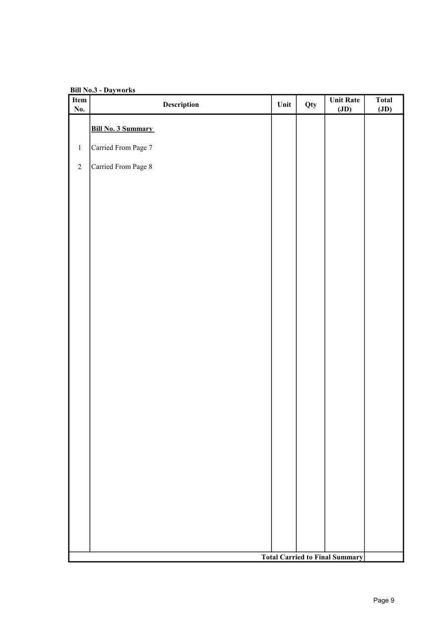
Bill No.3 - Dayworks
Bill No. 3 Summary
1 Carried From Page 7
2 Carried From Page 8
Total Carried to Final Summary
ItemNo. Description Unit Qty Unit Rate
(JD)Total (JD)
Page 9