Embed Size (px)
Citation preview

THE HARDWARE OF THE KDF9by BILL FINDLAY
1: KDF91.1: BACKGROUND AND OVERVIEWAnnounced in 1960, the English Electric KDF9 [Davis60] was one of the most successful products of the early UKcomputer industry. Even in an era of architectural experimentation, the designers of the KDF9 were bold andinnovative. The CPU used separate hardware stacks for expression evaluation and for subroutine linkage. Its threeconcurrently-running control units shared the work of fetching, decoding, and executing machine code instructions,synchronized by a variety of hardware interlocks.
The KDF9 was one of the earliest fully hardware-secured multiprogramming systems. Up to four programs could berun at once under the control of its elegantly simple operating system, the Timesharing Director. Each program wasconfined to its own core area by hardware relocation, and had its own sets of working registers, which were activatedwhen the program was dispatched, so that context switching was efficient. A program could drive I/O devices directly,but was limited by hardware checks to those the Director had allocated to it.
This paper is one of a series. Companion papers provide a synoptic description of the KDF9’s architecture andsoftware [Findlay18]; a detailed description of the KDF9’s various software systems [Findlay19a]; and an account ofKDF’s rôle in the development of computer performance benchmarking [Findlay19c]. Here I focus on the hardware,especially on the instruction set and its implementation. It may be useful to read [Findlay18] before the present work,which deepens that account, but it is not in the least necessary, as all essential material is repeated.
My primary sources are EE internal engineering reports [EEC62a, b, c], and the nearest thing we have to a KDF9reference manual: the KDF9 Programming Manual [ICL69], called simply ‘the Manual’ in the following.
A comprehensive bibliography of extant KDF9 documents is provided in [Findlay19d], which is updated from timeto time as new sources come to light. Much of this material is available online.
1.2: AUTONOMOUS UNITS AND THEIR STORESA KDF9 computer has three primary and many secondary control units, all microprogrammed and running in parallelwith each other, subject to appropriate interlocks. A useful way to think of its large-scale structure is as a community ofcooperating finite-state machines. The whole complex works to the beat of a clock giving two pulse trains (P1 and P2)each of 0.25µs/0.75µs mark/space ratio, and 0.5µs out of phase.
The primary control units are Main Control (MC), Arithmetic Control (AC), and I/O Control (IOC). Accordingto a personal communication from Michael Wetherfield—one of the designers of the KDF9 architecture—this divisionof responsibility was suggested, at least in part, by somewhat earlier plans for the ILLIAC II [UofI58].
MC takes most of the responsibility for instruction sequencing, including instruction fetching, jumps, subroutines,and interrupts; for mediating access to the KDF9’s various stores; and for address generation and indexing. The main(core) store has up to 32768 words, each of 48 bits. The Q Store is a bank of 16 index registers, each of 48 bits. TheSubroutine Jump Nesting Store (SJNS) is a stack of 16-bit return addresses, with maximum depth 17 links.
AC directly executes simple ALU instructions, and delegates to the Multiplier/Divider unit and the Shift unit, formore complex arithmetic operations. AC operands are taken from, and results returned to, the nesting store (or nest),which is an expression-evaluation stack with maximum depth 19 words. In addition there is a 1-bit Overflow Register,typically set when the range of a result is exceeded, and a 1-bit Boolean Test Register.
Note the absence of a conventional ‘program counter’ register. This is explained later.IOC supervises up to 16 DMA channels (known as buffers in KDF9 terminology) that are capable of simultaneous,
independent transfers. Each buffer operates under the control of its own autonomous microprogram. IOC is responsiblefor the Lock-Out Store—one bit to every 32 words of main store, for mutual exclusion of CPU and I/O transfers.
The Lock-Out Store, Q Store, SJNS and nest are implemented with the same technology: as core storage with a readcycle time of 1µs and a write cycle time of 1.5µs. The main store is comparatively slow, having a read or write cycletime of 6µs, and the architecture of the KDF9 goes to some lengths to mitigate the effect this has on performance.
None of these stores have parity checking.A hardware timesharing option replicates the nest, SJNS and Q Store, so that four register sets are provided,
thereby obviating the need to save and restore 48 registers when context-switching between a maximum of fourconcurrently running processes or problem programs. KDF9 runs under the supervision of a Director program, a set ofprivileged routines normally resident at the bottom of store. Its main function is to respond to interrupts, and therebyprovide essential services to problem programs, including management of the timesharing facility. (In the UK computerparlance of the early 1960s, a ‘timesharing’ system implements multiprogramming, not multi-user interactivity.)
A more unusual type of storage holds the microprogram in the sequence units, which direct the actions of MC, AC,IOC, and the buffers. The bits in these stores are fabricated by pulse transformers. These are large ferrite toroids,about 1cm in diameter, with multiple secondary windings. When a transformer’s primary winding is pulsed, itssecondary windings emit a variety of control signals.
The fastest storage elements, registers accessed in critical paths, are made from transistor flip-flops. Transistors arealso used and as amplifiers for the outputs from core stores and pulse transformers. A KDF9 includes something on theorder of 20,000 transistors—a remarkably low figure for such a sophisticated machine, and testimony to its philosophyof gaining speed through clever design instead of heroic expenditure on hardware. Perhaps we glimpse the ghost ofTuring, whose computer designs were predicated on exactly the same attitude.
© 2019-08-04 William Findlay ([email protected])This document is licensed under a Creative Commons Attribution 3.0 License: http://creativecommons.org/licenses/by-nc-sa/3.0/
1

1.3: DATA FORMATSA KDF9 data word consists of 48 bits numbered from D0 (the most significant bit) to D47 (the least significant). Similarbig endian numbering is applied to part-word bit fields. Several data formats are supported:• as a 48-bit, 2’s complement binary integer, fraction, or fixed-point number• as a 48-bit floating point number, consisting of a sign in D0, an excess-128 exponent in D1-D8, and a mantissa in D9
to D47; where the mantissa, together with D0, forms a 2’s complement fraction of 40 bits• as half of a 96-bit, 2’s complement binary integer, fraction, or fixed-point number, where D48 (D0 of the second
word) is set to zero, so that the effective capacity is 95 bits• as half of a 96-bit floating point number, consisting of sign in D0, excess-128 exponent in D1-D8, a first part of the
mantissa in D9 to D47, D48 set to zero, and a second part of the mantissa in D57-D95; where D49-D56 are set equal to (exponent – 39) unless that would be negative, in which case the whole of D48-D95 is set to 0; and where the mantissa, together with D0, forms a 2’s complement fraction of 79 bits
• as two 24-bit halfwords• as eight characters of 6 bits each• as three 16-bit 2’s complement integers that constitute the Counter (C-part, D0-D15), the Increment (I-part, D16-
D31) and the Modifier (M-part, D32-D47) of an indexing word in Q Store format• as a control word for I/O instructions, in which the C-part is a device number; the I-part a main store start-address, or
unused; and the M-part a main store end-address, or an operation count, or unusedSingle-precision floating-point results are usually rounded: 1 is added to D47 of the result if the first truncated bit is
not 0; but double-precision results are always unrounded: the truncated bits are ignored. Floating-point results arealways standardised (normalised, so that D0 ≠ D9); the only floating point operation that gives a well defined resultfrom a non-standardised operand is the STAND instruction, which effects normalisation.
There are no double-word fetch or store instructions: double words need a pair of fetch or store instructions to copythem into or out of the nest. The less significant word of a pair is held in the deeper of its two nest cells.
There are instructions for fetching and storing 24-bit halfwords. Fetching a halfword expands it to a full word in thenest by filling in the 24 least significant bits with zeros. Storing a halfword from a word in the nest extracts its mostsignificant 24 bits. A halfword can hold a 24-bit 2’s complement binary integer, fraction, or fixed-point number, or afloating-point number (the latter consisting of the most significant 24 bits of the 48-bit floating-point format).
I/O devices employ 6-bit characters, up to eight of which can be held in one word; however there are no facilities toaddress packed characters in main store. Characters are packed into words beginning at the most significant six bits.Conveniently, in all the KDF9 character codes, six zero bits represent a blank (space) character; and six one bitsrepresent a filler character, which legible output devices such as the line printer and Flexowriter completely suppress.For a full listing of the character codes used by the various I/O devices, see Appendix 4.
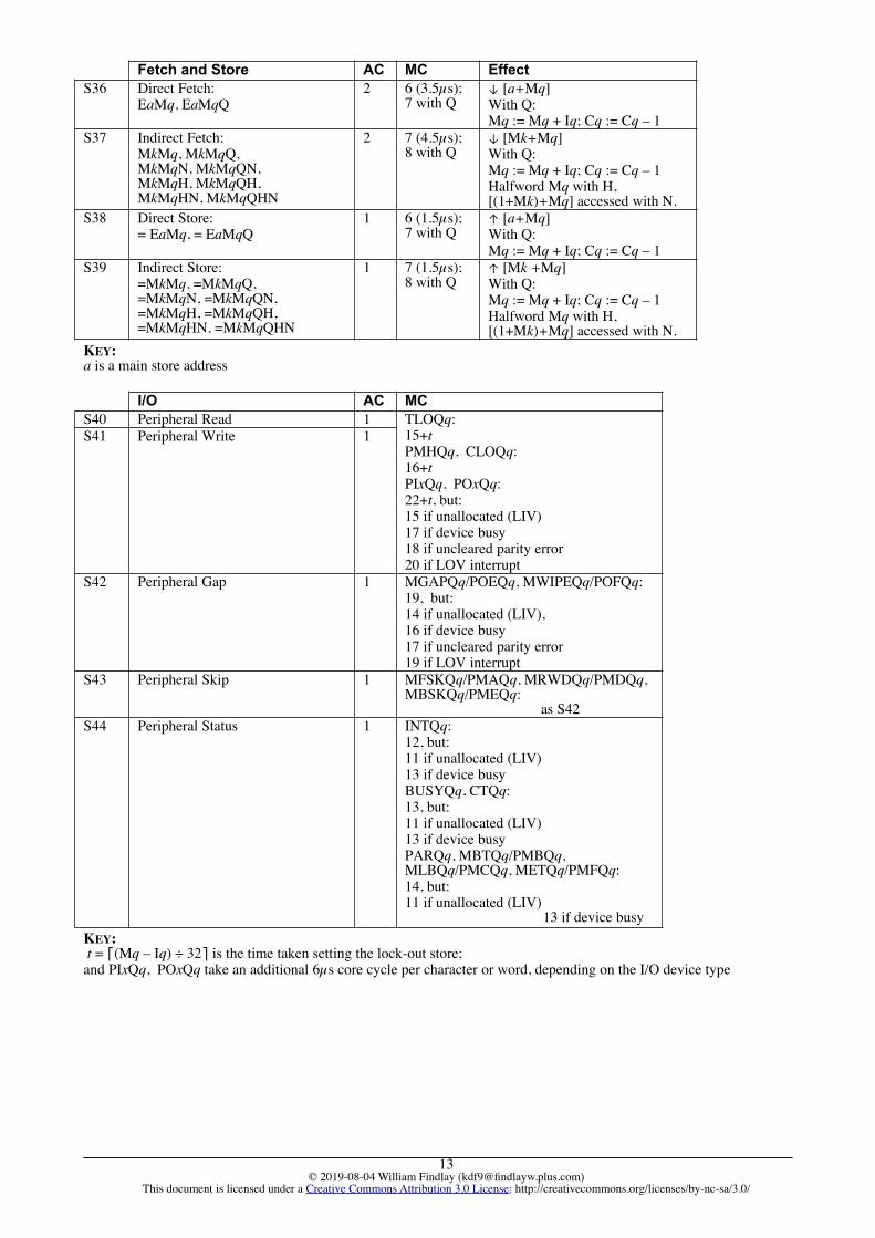
1.4: INSTRUCTION FORMATSA KDF9 instruction consists of one, two or three syllables of eight bits, the first two bits of each instruction giving itstype, which is 002 for one-syllable instructions, 012 for two-syllable instructions, 102 for three-syllable jumps, and 112
for ‘directly addressed’ fetch and store instructions of three syllables. Each instruction word is therefore capable ofholding between two and six instructions, dependent on their lengths.
One-syllable instructions do not contain an operand address or other parameter, and operate only on the nest in‘Reverse Polish’ style. They are carried out by AC (Arithmetic Control). Instructions of two or three syllables areprimarily the responsibility of MC (Main Control). Two-syllable operations include all operations that require one ormore Q Store numbers—‘indirect’ memory fetches and stores, operations on the contents of Q Stores, shift orders, I/Oorders, and the special JrCpNZS jump instruction. Three-syllable jumps contain a 16-bit instruction address. Directlyaddressed fetch and store orders contain a 15-bit word address, and the SET instruction contains a 16-bit constant.
The KDF9 assembly language, called Usercode [EEC69], is very unusual in having a ‘distributed' syntax thatembeds parameters within the Usercode order. For example, the J10C2NZ instruction means ‘Jump to label 10 if the C-part of Q Store 2 is Not Zero’. It is possible that this format was suggested by the order code, which distributes opcodeand address bits around the machine instruction in an equally unconventional manner—see Appendix 2.
Usercode instructions are labelled by integers. An asterisk preceding a label forces the following, labelled,instruction to start at syllable 0 of a fresh word, any unused syllables of the preceding word being padded withDUMMY (no-op) instructions. This is necessary for the target label of a JrCpNZS instruction, which does not containan address, but jumps to syllable 0 of the word before that containing the JrCpNZS itself.
2: THE CPU2.1: MAIN CONTROL, ARITHMETIC CONTROL AND I/O CONTROLKDF9 comprises two blocks: the I/O block and the Computing block. The I/O block is provided with instructions by theComputing block, but otherwise works independently, taking priority for access to main store. The Computing block iscomposed of MC and AC. MC works collaboratively with AC. They interact most strongly on conditional jumps, whereAC computes the Boolean; on shifts, where MC calculates the shift length and AC performs the shift; and onfetches/stores, where MC transfers data to/from the store and AC transfers it to/from the nest. The latter, in particular,does much to compensate for the relatively slow core store.
For a fetch operation, MC initiates a store read. A word is transferred from the store to whichever of two fetchbuffers is empty. If both contain data that has not yet been delivered to AC, the transfer is delayed until AC catches up.The fetch buffers mean that MC can complete up to two fetch instructions, their core cycles being overlapped withcomputation by AC. This is particularly valuable in the very frequently executed inner loops that evaluate scalarproducts. (KDF9 was very much a ‘scientific’ computer.) For a store operation, MC saves the destination address in aregister; when AC catches up it copies the value from the nest into a store buffer register. When convenient, MC copiesthe contents of the buffer register to store. Instruction fetching is also the responsibility of MC. There are twoinstruction-word buffers. MC fetches an instruction word to the instruction-word buffer that is not currently beinginspected by AC. Thus instruction-fetching can also overlap with computation by AC.
© 2019-08-04 William Findlay ([email protected])This document is licensed under a Creative Commons Attribution 3.0 License: http://creativecommons.org/licenses/by-nc-sa/3.0/
2

The art of ‘optimum programming’ on KDF9 is concerned with the careful relative placement of fetch, store, jumpand arithmetic operations, with a view to maximizing the parallelism between store cycles and calculation. In thisrespect KDF9 is very like modern CPUs.
2.2: ADDRESSING AND THE Q STOREProblem programs address their instructions and data starting from a virtual effective address of 0. When store isaccessed, the hardware offsets this address by the program’s starting position in main store. At the same time it checksthat the virtual address does not exceed the number of locations allocated to the program by Director. In Director stateno offsetting is done, so that Director starts at physical location 0.
The address part of a jump instruction consists of a 13-bit word number and the 3-bit number of a syllable withinthat word. Consequently, the instructions of a program are confined to its first 8192 words. EXIT (return fromsubroutine), EXITD (return from Director to a problem program) and OUT (invoke Director from a problem program)all have the same basic format as a jump. EXIT’s address part is treated as an offset, to be added to the link in the SJNS.
Effective addresses for data fetches and stores are generated in either of two ways: by 3-syllable instructionscontaining a 15-bit constant address part and a single Q Store reference, Qq; or by 2-syllable instructions containing twoQ Store references, Qk and Qq. The effective address in the first case is the sum of the constant and the contents of Mq;in the second case it is the sum of Mk and Mq. Q0 always contains 0, providing a handy way of getting a zero base.
Data locations in EE Usercode have rigidly stereotyped identifiers. Local variables of subroutines have names of theform Vm; global variables have names of the form Wm, Ym, YAm, …, YZm. If indexed, the identifier is followed by‘M’ and the Q Store number; the 2-syllable instructions take the operand form ‘MkMq’. Usercode instructions such asV9; YA7M2; M1M2; and so on, represent data fetches that push values onto the nest; =V9; =YA7M2; =M1M2; and soon, represent data stores that pop values from the nest.
Flags suffixed to the instruction optionally specify index updating, halfword addressing, and ‘next word’ addressing.The ‘Q’ suffix causes the Qq register to be updated, after the effective address is determined, by adding the contents
of Iq to Mq and decrementing the contents of Cq. This allows stepping through a predetermined (but variable) numberof locations, at addresses given by an initial address and a predetermined (but variable) stride. There are conditionaljump instructions that test whether the C-part of a Q register is (non-)zero, providing for very efficient counting loops.
The ‘H’ suffix, on a 2-syllable fetch or store order, causes the operand accessed to be a halfword. In this case thecontent of Mk is taken as a base word address, and the content of Mq is taken as a halfword offset, odd-numberedhalfwords being those in D24-D47 of the addressed word.
The ‘N’ suffix, on a 2-syllable fetch or store order, causes the accessed word to be at an address 1 greater than usual(i.e., the next word). This allows efficient processing of arrays of pairs of elements stored sequentially in adjacent words—such as the constituent words of a double-precision number—since Qq needs to be updated only once for every wordpair, using an increment part set to 2. All combinations of Q, H, and N, in that order, are permitted in a 2-syllable fetchor store order.
The 3-syllable fetch and store orders take 6µs, the 2-syllable fetch and store orders take 7µs, and an additional 1µs isneeded for Q register updating in both cases. It is merely coincidental that the time taken by 3-syllable fetch and storeorders is the same as the main store read/write cycle time—the core store cycle does not begin until 1.5µs-3.5µs afterthe start of the instruction and the 6µs it takes is not included in the total, as it overlaps with following instructions.
2.3: EXPRESSION EVALUATION AND THE NESTAn adder associated with the Q Store carries out the arithmetic involved in Q Store updating and in computing effectiveaddresses. All other calculations, both fixed-point and floating-point, involve the nest. It is common for parameters of asubroutine to be supplied in the nest, especially when the routine implements an arithmetic function.
The top three cells of the nest (N1 at the top, then N2 and N3 as we go deeper) are held in three flip-flop registers.The N-registers are managed, transparently to problem programs, by a combination of hardware logic and Directorsoftware. When a value is pushed onto the nest, hardware saves N3 in the nest’s core stack, N2 in N3, N1 in N2, and thenew value in the vacated N1. Popping a value is the simple converse.
At most 16 nest cells are available to a program. The Nest Over-/Under-flow Violation (NOUV) interrupt happensafter pushing a 17th value, or after popping an empty nest. Since an interrupt is not effected until it is convenient forMC, AC may have performed several further nest operations, leaving the contents of the nest unpredictable.Consequently, no recovery from NOUV is possible for a problem program.
Keeping track of nest depth is one of a KDF9 programmer’s main chores, and NOUV interrupts are among the mostcommon results of programming error. In a modular program with deeply nested subroutines it can be difficult to ensurethat NOUV is always avoided. Routines can save (on entry) and restore (before exit), all or part of the nest contents;they are helped in this by conditional jumps that test whether the nest is empty (JrEN) or not (JrNEN).
It often happens that the order of operands in the nest, while convenient for some purposes, is inconvenient forothers. To reorganize the nest, we have the 1-syllable instructions:• REV: a, b, … b, a, …• DUP: a, … a, a, …• ERASE: a, … …
• CAB: a, b, c, … c, a, b, …• PERM: a, b, c, … b, c, a, …• REVD: a, b, c, d, … c, d, a, b, …• DUPD: a, b, … a, b, a, b, …
Simple instructions—including integer +, –, AND, OR, REV, DUP, ERASE, etc—take from 1µs to 4µs, 2µs beingtypical. Floating-point addition takes from 7µs, multiplication takes from 14µs, and division takes from 36µs; thevariation being due to data-dependent operand alignment and result normalization. Overflow is set on division by zeroand when a numerical result is outside the range of the result type. It remains set until explicitly cleared.
The 1-syllable ZERO and the 3-syllable SET allow for the sourcing of small constants. The most efficient way topush -1 is: ZERO; NOT; and the most efficient way to get +1 is: ZERO; NOT; NEG;—the same number of syllables asSET 1; but slightly faster. Subtracting 1 is best done by: NEG; NOT; and adding 1 by: NOT; NEG. It is nice that these‘hacks’ set the overflow in exactly the same cases as SET 1; +; or SET 1; –;.
© 2019-08-04 William Findlay ([email protected])This document is licensed under a Creative Commons Attribution 3.0 License: http://creativecommons.org/licenses/by-nc-sa/3.0/
3

Some more unusual operations include SIGN, which replaces N1 with –1, 0, or +1, according to its sign; MAX,which arranges that N1≥N2, setting overflow if they were exchanged; and BITS, which replaces N1 with a count of thenumber of 1-bits it contained (it is interesting to speculate that BITS may stem from Turing’s cryptological work). TOByields a binary integer from a mixed-radix integer and a radix pattern; and FRB does the converse. For a full list ofinstructions, with execution times, see Appendix 1.
2.4: CONTROL FLOW AND THE SJNSThe Jr instruction is an unconditional jump to the instruction at label r. The instructions: Jr=Z, Jr≠Z, Jr>Z, Jr≥Z, Jr<Z,Jr≤Z test the sign of the top cell of the nest; to compare the top two cells of the nest we have: J r= and Jr≠. All of thesepop N1 whether they jump or not; Jr= and Jr≠ do not pop N2, being the only dyadic operations with this behaviour. Totest whether Cq is (non-)zero we have: JrCqZ, JrCqNZ, and JrCqNZS. The JrV and JrNV instructions are conditionalon the Overflow Register being (un-)set, while JrTR and JrNTR are conditional on the Test Register being (un-)set.Jr(N)V and Jr(N)TR clear the designated register, whether they jump or not.
JrCqNZS is known as the short loop jump. It jumps, if Cq is nonzero, to syllable 0 of the instruction word thatprecedes the word containing the JrCqNZS instruction; and has the further effect of inhibiting instruction fetch cycles.Thus the loop executes entirely from the instruction word buffers, with no overhead for instruction fetches. Importantalgorithms, such as scalar product and polynomial evaluation, fit comfortably into the 12 available syllables.
The JSr instruction branches unconditionally to the instruction at label r, and pushes its own address onto the SJNSas a return link. This creates issues of SJNS management similar to those that arise with the nest, and the instructionsJrEJ and JrNEJ are provided analogously to JrEN and JrNEN. The only other instructions that access the SJNS are:• EXIT a: complementary to JSr—pops the link from the SJNS, adds the constant a (which is an integral multiple of
three syllables), and branches to the resultant address• OUT: pushes its own address onto the SJNS and causes an OUT interrupt, thereby switching control to Director• EXITD: complementary to OUT, but also used when context-switching—pops the link from the SJNS and branches to
the resultant address in program state, with interrupts enabled on completion• LINK: pops a link from the SJNS and pushes it onto the nest• =LINK: pops a link from the nest and pushes it onto the SJNS
Normal return from a subroutine is effected by EXIT 1; if there is an abnormal return path, it is taken by EXIT 1;and EXIT 2; is the normal return. Switches are programmed by putting the index into the SJNS, by means of the =LINKinstruction, then the EXIT ARr instruction jumps to the selected word in the jump table starting at label r.
All interrupts, like OUT, use the SJNS for their return address.
3: INPUT/OUTPUT
3.1: PERIPHERAL DEVICESUp to 16 I/O buffers can be fitted. Each has its own independent control unit, which is microprogrammed to support itsconnected device. The monitor console Flexowriter is always on buffer 0, and a paper-tape reader with hardwarebootstrap facility is always on buffer 1. Communication with the operators is by means of messages typed on theFlexowriter, which has a button that is pressed to gain the attention of Director by causing a typewriter interrupt.(Merely using the keyboard does not cause an interrupt.)
Peripheral devices fall into two classes: slow, or character devices; and fast, or word devices. Buffers for slowdevices do a core cycle for each character transferred; fast device buffers do a core cycle for each complete word.
The slow devices include the Flexowriter (10ch/s), paper tape punches (110ch/s), paper tape readers (1000ch/s), cardreaders (10 card/s), card punches (5 card/s), graph plotters (200 step/s), and line printers (15 line/s).
The native KDF9 paper tape code is rather odd, and makes poor use of the eight punchable locations, or ‘channels’,in a tape frame. Channels 1-4 and 6-7 encode the six-bit character and channel 5 establishes even parity for the wholeframe. But channel 8 is used only to distinguish completely blank tape from the space (SP) character, which has the all-zero code. (Since SP has even parity it would otherwise be represented by a frame with no punching.) Blank tape, anderased tape with all channels punched, are treated as content-less leader or trailer. In normal input modes they areskipped over by the buffer and not transferred. These peculiarities are inherited from the offline Flexowriter tape-punchstations used for data preparation and for the transcription of output tapes to typed copy.
The paper tape code has ‘Case Shift’ and ‘Case Normal’ characters to expand the character set. Flexowriters treatthem literally—on receiving a Case Shift character, they shift up the type bars so that an alternative glyph can be printedfor each code. For example, the data ‘Bill Findlay’ would be punched on tape as ‘BßILL ñFßINDLAY’, where Ihave used ß to denote the non-printing Case Shift and ñ the non-printing Case Normal. Transcribing a tape containingthe characters ‘BßILL ñFßINDLAY’ types out the text ‘Bill Findlay’.
Calcomp drum plotters (models 563, 564, 565 and 566) are an option. They are attached to tape punch buffers,which are manually switchable between punch and plotter. An I/O instruction is provided to test the position of theswitch. The plotter takes 6-bit codes that move the pen and/or the paper by one step of fixed size at a time. Dependingon the particular Calcomp model, steps are of size 0.01 or 0.005 inches, and are taken at the rate of 200 steps/s.Commands to raise or lower the pen take 0.1s. The paper is a roll up to 120 feet in length, and either 11 inches or 29.5inches wide, depending on the model. Strangely, according to the Manual, a step in only one of the diagonal directionsis available as a single code; a step on the other diagonal requires separate pen and paper steps. This is almost certainlya typo; external evidence provides convincing reasons for, and the codes of, the other diagonals.
Card readers and punches have two modes of operation. In the ‘alphanumeric’ mode each column corresponds toone character and is encoded or decoded accordingly. In the ‘direct’ mode the 12 rows of each column correspond to the12 bits of two characters and are transferred literally. Line printers use a subset of the alphanumeric card code.
The fast devices are magnetic tape decks, fixed-disc drives, and drum stores.The magnetic tape physical format uses 16 tracks across the tape: six data tracks, a parity track and a clock track are
duplicated for each character. A character is valid if either copy can be read without error. Tapes run at 100inch/s, with400ch/inch, for a transfer rate of 40kch/s. Inter-block gaps are about 8-9mm long. A faster, but seldom seen, magnetictape deck runs at double speed (80Kch/s), recording on a steel band instead of plastic tape.
The fixed-disc drive has 17 disc platters, measuring about 31 inches in diameter. Disc blocks hold 40 words (320characters); there are 16 blocks per track in an outer recording zone (further from the spindle) and eight per track in an
© 2019-08-04 William Findlay ([email protected])This document is licensed under a Creative Commons Attribution 3.0 License: http://creativecommons.org/licenses/by-nc-sa/3.0/
4

inner zone. The discs spin at 1000 rev/min: the transfer rate in the outer zone is about 85Kch/s, but only half that in theinner zone. Fixed heads are mounted on the 17th platter, providing access to 96 of the fastest blocks without a seek.Each of the other 16 platters has its own independent actuator, which carries eight read/write heads. Both surfaces of aplatter have two heads in the inner track zone and two in the outer zone, so that 96 blocks are available without a seek.Seeks take from 156ms to 367.5ms, with an average of 231ms. The heads can be moved to 64 different positions, givinga capacity of 6144 blocks per platter, or 98304 blocks (31,457,280 characters) per drive. Up to four such drives can beattached to a disc buffer.
A drum consists of 320 addressable sectors, each of 128 words, for a total of only 40960 words of storage, accessedat a transfer rate of 500kch/s. Up to four units may be fitted to a drum buffer. Drums are of use mainly for storingfrequently executed programs, such as the program source editors and compilers. KDF9 configurations do not ordinarilyinclude drums, which offer a mutually exclusive alternative to fixed-disc drives.
3.2: I/O INSTRUCTIONSThere are two significant aspects to the software control of I/O devices on KDF9: their allocation to problem programsby Director, and their control by problem programs once allocated.
Programs can directly drive I/O devices on buffers allocated to them by Director. Any attempt to access anunallocated buffer causes a Lock-In Violation (LIV) interrupt, and termination of the program. This feature of KDF9means that programs are inherently device-dependent: they must contain logic specific to the type of device they use.This is less of a disadvantage than it might seem, because card reader/punches, paper tape reader/punches, and printers,all use somewhat different characters sets; so programs have to be device-aware for that reason, if no other.
Though program logic is coupled to device type, it is decoupled from device identity. To obtain access to a device, aprogram asks Director to allocate it one of the type. If such a device is available, Director allocates it to the program andreturns its buffer number in N1. The program must save this number for future use.
The instructions that control devices take their parameters from a designated Q Store, Qq. Cq contains the buffernumber of the device. (For the fixed disc system, Cq also contains the seek area number, the platter number and thedrive number, taking up all 16 bits.) Depending on the specific instruction, Iq and Mq might contain starting and endingvirtual addresses for a data transfer operation, the transfer count being determined by their difference; or Mq mightcontain a repetition count for a control operation; or Iq and Mq might both be ignored.
If the least significant bit of an I/O instruction is 1, it sets the device off-line before initiating the operation. Thedevice is only set on-line by the operator pressing a button on its control panel. In this way a program can set up atransfer on a tape reader, for example, which waits until the operator has loaded a tape before attempting to read.
After checking its validity, MC delegates an I/O instruction to its specified buffer, via IOC; if it is a data transferinstruction, MC also provides physical addresses converted from the virtual addresses given in Iq and Mq.
There is some attempt at making the effect of a given instruction generic, so that PIAQq, say, acts in a similar wayon all input-capable devices, but this is not carried through with complete consistency. Some simpler devices respond todifferent orders in the same way: PIAQq and PIEQq, for example, have the same effect on a paper tape reader.
A completely generic feature of the I/O architecture is the provision of variable length transfer instructions. Thesetake a (maximum) transfer count, as usual, but terminate early upon transferring an End Message character (written‘’, code 758). When a variable-length read terminates on End Message, any remaining character positions of the lastword transferred are set to zero (a SP character). In the case of fast devices, when a variable-length write terminates onEnd Message, any remaining character positions of the last block transferred are set to zero on the output device.
Another feature, generic to the slow devices only, is the availability of the misnamed character transfer option.These instructions read one character into, or write one character out of, the least significant bits of each word in thetransferred area. This is the only I/O mode that permits the transfer of an arbitrary number of characters without the sideeffect of termination on End Message. When applied to paper tape, character mode further allows for all eight bits of aframe to be read or written, so that foreign codes can be handled (at the cost of forgoing hardware parity checks).
A peculiarity of the online Flexowriter is that, when a semicolon is written, the write operation changes itself on-the-fly to a read operation; subsequent typed input is transferred to the originally designated output buffer, in characterpositions following the semicolon. This can be used to program an atomic, prompt-and-response, form of interaction.
The PMxQq instructions provide control operations, such as rewinding a magnetic tape or initiating a disc arm seek. Several instructions enable device-dependent state (e.g., whether a magnetic tape is positioned at the Beginning Of
Tape window) to be transferred to the CPU’s Test Register; these instructions are also encoded in the PMxQq group.PARQq and BUSYQq both transfer state from a buffer to the Test Register. BUSYQq checks whether a buffer is
presently engaged in a transfer. PARQq checks and clears a parity error flag on a buffer’s last completed transfer—anyother command to a buffer with an uncleared parity error causes a LIV interrupt.
The Usercode programmer is given multiple, device-specific mnemonics for each hardware I/O instruction. Forexample, the output instruction POAQq can also be written as MWQq when the intended output device is a magnetictape drive, and as TWQq when it is the console typewriter. The use of a specific mnemonic has no significance at runtime; effectively it acts like a comment appended to an unspecific mnemonic in the source program.
Only a fraction of many possible I/O opcodes have defined effects. Moreover, some are defined only for one class ofdevice (input or output). Attempting an undefined I/O operation causes a LIV interrupt. See Appendix 3.
3.3: I/O-DRIVEN MULTIPROGRAMMINGProgram blocking by I/O operations is automatically managed by IOC, using a 12-bit Program Hold-Up (PHU)register for each of the four program priority levels.
While an I/O transfer is in progress, its core store area is locked out by the buffer, so that any attempt to access itconcurrently, whether to fetch or store data, to fetch instructions, or use it for another I/O transfer, causes a Lock-OutViolation (LOV) interrupt. Attempting an I/O operation on an already-busy buffer also causes a LOV. In response to aLOV, Director suspends the responsible program. One bit of the Lock-Out Store is associated with each group, or blockof 32 words, so for greatest overlap it is important to ensure that I/O areas are aligned on 32-word boundaries.
The PHU registers are constituted as follows:• PHUn:D11 is set if program level n is held up.• If PHUn:D10 is 1 then PHUn:D6-D9 contain the number of the buffer on which program level n is waiting.• If PHUn:D10 is 0 then there is a core lock-out in effect and PHUn:D0-D9 contain the number of the locked-out group.
© 2019-08-04 William Findlay ([email protected])This document is licensed under a Creative Commons Attribution 3.0 License: http://creativecommons.org/licenses/by-nc-sa/3.0/
5

A buffer records the CPU’s privilege state at the start of a transfer. On completion, if Director started the transfer,IOC requests an End of Director Transfer (EDT) interrupt; but if the transfer belonged to a problem program, its PHUis cleared. If the cleared PHU belongs to a program of higher priority than the one currently running, IOC requests aProgram (PR) interrupt. Since a suspended program may be waiting on a shared device (typically, the Flexowriter)made busy by a program of lower priority, every other PHU is then examined to see if it refers to the same buffer. If so,an EDT interrupt is requested instead of PR. This enables Director to take suitable action to resolve the priorityinversion over the shared device.
Applying an INTQq instruction to a busy buffer also causes a PR interrupt, effectively yielding the CPU to aprogram of lower priority; applying INTQq to an idle buffer has no effect. PHUn:D0 is set to 1 if an INTQq instructionis responsible for program level n being held up.
3.4: I/O CONTROLIOC provides the interface between the CPU and the I/O devices on their buffers. It contains three sequence units. TheESU1 and ESU2 units provide a conduit for the transfer of data between main store and the buffers. The RSU initializesand finalizes I/O transfers, manages the Lock-Out and PHU Stores, and passes the parameters of the I/O instruction tothe relevant buffer. At the end of the transfer the RSU requests the appropriate interrupt from MC.
The C Store provides one 48-bit word for each buffer. It contains the transfer’s initial, final and current wordaddresses, the 2-bit priority level at which the transfer was requested, and a flag for Director transfers. The initialaddress is retained to allow a fast-device operation to be restarted automatically should a parity error be detected duringthe transfer. Slow device buffers use those 15 bits for different purposes: they hold the next character position withinthe current word, and indicate transfer options such as ‘character’ mode.
The E Store is a 16×4-bit FIFO that the buffers use to request service from IOC. When it needs attention, a bufferinserts its device number at the end of the E Store. The ESUs take the buffer number at the head of the FIFO, using it toselect a C Store and so discover what needs to be done. The IOC can be seen as a multiplexor channel, in more modernlanguage, capable of both byte and word transfers, but not having a ‘burst’ mode, locked on to a single device. The totalI/O rate of the maximum complement of EE devices (8 of the faster tape decks, a disc drive, and a drum store—slowdevices are irrelevant) does not exceed the bandwidth of the core store, so burst mode is not needed. However, oneinstallation [WR67] did modify the E Store mechanism to allocate store cycles on a priority basis, with higher priorityfor faster devices, their motivation being the need to connect a very fast non-standard device.
4: DIRECTOR STATE
4.1: INTERRUPTSKDF9 interrupts may be either voluntary (OUT or INTQq obeyed by the problem program); inadvertent (illegalinstruction, nest over-/under-flow, etc); or housekeeping (monitor typewriter, clock and I/O device interrupts).
The special register RFIR (Reason For Interrupt Register) records the currently requested interrupt(s). RFIR isinspected from time to time by MC. When an interrupt is accepted, control branches to word 0 of Director, leaving aninstruction address in the top cell of the SJNS. On entry to Director state, NIFF (Non-Interrupt Flip-Flop) is set toinhibit further interrupts, but not their recording. However, the RESET interrupt is never inhibited and the NOUVinterrupt is completely suppressed. NIFF is also, in effect, the Director-state flag, so that an interruptible Director modeof execution does not exist.
When fetched by the privileged K4 instruction, RFIR is automatically cleared. K4 delivers the following to N1:• D0-D15: CLOCK COUNT; the integer in D0-D15 is incremented every 32µs; a CLOCK interrupt occurs when
overflow from D1 sets D0, but if D0 is already set a RESET interrupt occurs instead (‘double clocking’)• D22: the PR interrupt is caused by the end of a peripheral transfer started by a program of higher priority than the
program currently running; the PR interrupt is also caused by an INTQq instruction applied to a busy device• D23: the FLEX (Flexowriter) interrupt is caused by the interrupt key on the console typewriter• D24: the LIV (Lock-In Violation) interrupt is caused by an illegal or privileged instruction, by the use of an
unallocated peripheral, by store address wraparound, or by a negative effective address• D25: the NOUV (Nest Over- or Under-flow Violation) interrupt occurs when an attempt is made to overfill an already-
full nest or SJNS, or to pop an already-empty nest or SJNS• D26: the EDT (End of Director Transfer) interrupt occurs at the end of a peripheral transfer initiated by Director, or if
a priority inversion has been detected among programs currently locked-out and waiting for a shared device• D27: the OUT (system-call) interrupt is caused by the OUT system-call instruction• D28: the LOV (Lock-Out Violation) interrupt is caused when a program attempts to access any of a locked-out group
of 32 words, or when it addresses a busy peripheral device other than by BUSYQq or INTQq• D29: the RESET interrupt is caused by jumping to an invalid syllable address (6 or 7), or by a watchdog ‘double
clocking’ (implying that a previous CLOCK interrupt has not been handled by Director in the intervening time)If a store-access instruction with Q Store updating experiences a Lock-Out Violation, the Q register update is
suppressed. When the lock-out clears, and the interrupted program is resumed, the instruction can be restarted withoutdoubly updating the Q register.
4.2: NESTING-STORE MANAGEMENT BY HARDWARE AND DIRECTORThe nest depth is represented by a 5-bit counter register. Its least significant four bits provide the address of the cell tobe accessed in the nest’s 16-word core stack. NOUV is signalled in program state when a push completes with the depthequal to 16+1, and when a pop completes with the depth equal to 0-1. Since NOUV is completely suppressed whenDirector is running, it can use all 19 nest cells—the 16 in the core stack and the three flip-flop registers, N1-N3.
To maximize hardware speed in a critical path, the destructive reading of a cell in the nest core stack is not followedby a write cycle to restore the contents; so reading a cell also clears it. As the nest is a strictly LIFO store, this is not aproblem: no attempt can be made to read the cleared value a second time.
Similarly, and again for speed, writing to a cell in the nest core stack is not preceded by a read cycle to clear it; sothe written bit pattern is effectively OR-ed into the cell. This is valid only if the cell contained zero before the writecycle. Therefore, before entering a program for the first time, Director completely empties its nest—not merely settingthe depth to zero, but explicitly clearing the contents. The ERASE order pops the nest, forcing a destructive read fromthe core stack into N3. By performing enough ERASE orders, Director can ensure that all 19 nest cells are completely
© 2019-08-04 William Findlay ([email protected])This document is licensed under a Creative Commons Attribution 3.0 License: http://creativecommons.org/licenses/by-nc-sa/3.0/
6

zeroized. Subsequent pushes, to a depth less than four, leave the state of the core stack unchanged, although the nestdepth increases. The first push that increases the depth to four may cause a non-zero value to be saved in the core stack(at cell 3). This leaves cells 0-2 clear, even when the nest depth reaches 16, the most allowed to a problem program.
Director’s short-path interrupt handler saves N1-N3 at zero cost, as a side-effect of pushing three of its own valuesonto the nest. There is always room for N1-N3 in the core stack—at worst, in cells 0-2. Before returning to aninterrupted program, Director performs three ERASE orders, thereby restoring the values that N1 -N3 contained beforethe interrupt. If the interrupted program’s nest depth was less than three, one or more non-significant zero words will befetched into the N-registers; since the NOUV interrupt is suppressed in Director, no harm results. The round-trip cost ofpreserving the nest in the short path is therefore just three ERASE orders, taking 3µs. This makes context switching inresponse to PR interrupts rather efficient, the time consumed between interruption and re-entering a program being ofthe order of 320µs, or about 60 instructions. The ‘long path’ through Director, where more complex work is done, mustsave more of the interrupted program’s registers; but that happens relatively infrequently.
If a program causes a NOUV interrupt by overfilling the nest, cells 0-2 of its core stack might be corrupted; but thisdoes not matter, because the program cannot be allowed to continue unless the nest and SJNS are re-initialized.
There is one weakness in the implementation of the nest—the depth is checked only after it changes. A consequenceof the reasoning described above is that, for correct LIFO operation, N2 must be clear when the nest depth is 1. ButREV, for example, can be executed when the depth is only 1, and may swap a non-zero value into N2 without a NOUV.Two pushes later this non-zero value enters the core stack, changing the pristine 0 in cell 2, so that a future write intothat cell will be corrupted. However, a program that commits such a gross error is likely to soon attempt a dyadicoperation, and will fail at that point. In any case, it affects only itself, and only by making its debugging more difficult.
The implementation of the SJNS is very similar to that of the nest, with a similar division of responsibility betweenhardware and software. The Jump Buffer, a single flip-flop register analogous to the nest’s three N-registers, constitutesthe 17th cell of the SJNS. It ensures that interrupts can be taken when the SJNS is full, and it promotes the efficiency ofthe Director’s short path. NOUV is caused after a program pushes a 17th link, and after it pops an empty SJNS. Theexcess link left in the Jump Buffer by a 17th push is overwritten by the NOUV interrupt’s return address. Again, thisdoes not matter, because the program cannot be allowed to continue unless the nest and SJNS are re-initialized.
4.3: DIRECTOR-ONLY REGISTERS AND INSTRUCTIONSSeveral special registers, concerned with multiprogramming, are accessible only to Director, although they exercisetheir influence on the running of problem programs.
The Base Address (BA), a 10-bit register, contains the number of the 32-location group of words at which theprogram starts. It is added to the top ten bits of virtual addresses to effect dynamic relocation. The Number OfLocations (NOL), also a 10-bit register, contains the BA-relative group number of the highest addresses the programcan validly access. I/O instructions specify virtual addresses in Iq and Mq. MC checks that Iq ≤ Mq, checks that bothare compatible with NOL, and adds to both the value in BA, before passing them on to IOC. A failed check causes aLIV interrupt. On entry to Director BA is set to 0, so Director runs at the bottom of core. Strangely, NOL is stillcompared with effective addresses in Director state; Director must set NOL to the maximum for the machine, if it wantsto guard against causing a LIV interrupt when accessing main store above its own upper limit.
The Current Peripheral Device Allocation Register (CPDAR), a 16-bit register, has one bit for each buffer. If abit is set, the program can validly command the corresponding buffer; if the bit is clear, any such attempt causes a LIVinterrupt. The Current Priority Level (CPL), a 2-bit register, holds the hardware dispatching priority of the program.
These registers contain values that are proper to one running program, and Director must set them accordinglybefore (re-)entering that program. The hardware timesharing option provides four instances of the nest, Q Store andSJNS. On context switching between programs, Director can switch quickly between instances by changing the activeset number, but must separately save and restore the nest depth, the SJNS depth, BA, NOL, CPL, CPDAR, and theOverflow and Test registers.
There are four of the PHU (Program Hold-Up) registers. For scheduling reasons, Director might want to change thepriority level of a program. Since a program’s priority fixes the PHU that is used by the buffers to update its dispatchingstatus, Director must wait for all of its I/O transfers to terminate before assigning it to a different priority.
Instructions to manipulate the special registers are available only in Director state. They are:• EXITD: clear NIFF and jump to the address in the top cell of the SJNS; interrupts are inhibited throughout the
execution of EXITD, to allow the machine to adopt a stable state• CLOQq: clear any lock-outs for the area specified by Iq and Mq, and clear PHUn, where n is the current value of CPL• TLOQq: test the area specified by Iq and Mq, setting the Test Register if any of the encompassed groups are locked
out• CTQq: terminate device activity and clear lock-outs for the transfer specified by Qq• =K0: if N1 ≠ 0 then switch buzzer on else switch buzzer off end• =K1: copy bits N1:D24-D33 to NOL, bits N1:D34-D35 to CPL and bits N1:D38-D47 to BA• =K2: copy bits N1:D32-D47 to CPDAR, where N1:D32 corresponds to buffer 15 and N1:D47 to buffer 0• =K3: switch to a new Q Store/nest/SJNS set, with N1:D0-D1 as the new register set number, N1:D2-D6 as the nest
depth and N1:D7-D11 as the SJNS depth• K4: push CLOCK/RFIR onto nest.• K5: push PHUi:D6-D11 onto nest, for i in 0..3, with PHU0:D6-D11 in N1:D0-D5, PHU1:D6-D11 in N1:D6-D11,
PHU2:D6-D11 in N1:D12-D17, and PHU3:D6-D11 in N1:D18-D23.• K7: push the current register set number and nest depths, as represented for the =K3 instruction.
The =K3 instruction must be followed by at least six DUMMY instructions, since it needs 6µs to take effect andduring this period the machine is in an indeterminate state. All =Kk instructions copy N1, and do not pop it.
Note that register sets are numbered independently of program priority levels. If Director exchanges the prioritylevels of a pair of programs, it does not need to swap the contents of their register sets.
Two other Director-only instructions have to do with I/O: PMGQq and PMHQq do not seem to have more specificUsercode mnemonics. The semantics of PMHQq are clear: it is a ‘set lock-out’ instruction, the complement of CLOQq.It is used in Director to lock out an area of core as it would have been by a data transfer, but without actually setting up
© 2019-08-04 William Findlay ([email protected])This document is licensed under a Creative Commons Attribution 3.0 License: http://creativecommons.org/licenses/by-nc-sa/3.0/
7
a transfer. PMGQq does not seem to be used in any extant Director, although it is attested in marginal notes takenduring a KDF9 training course, where it is described as ‘read C Store’. Perhaps it is used in I/O diagnostic programs.
5: MAIN STORE ORGANISATIONMain store is composed of modules of 4K words, each consisting of four 1K blocks. A block consists of 48 core planesof 32×32 bits (the Z, X and Y directions, respectively), the whole organised as follows.
Registers associated with the main store include the 15-bit main-store address register (MSAR) and the 48-bit mainbuffer (MSB). The most significant three bits of MSAR give the module number, the next two give the block within themodule, the next five give the X-line and the last five the Y line. A series of decoding matrices interpret each of thefields, giving access either to a further matrix, or, eventually, to the X and Y lines themselves.
The read sequence operates as follows:1: the matrix system is pulsed to select the X and Y wires. The cores that flip produce a detected signal in the readout
wires, which are organised one per XY plane, per module. The output from the read amplifiers is transferred to MSB. If reading is to be inhibited on certain planes (i.e. for a halfword access), an inhibit current cancels the effect of the X-line current and the cores on those planes do not flip.
2: A side effect of the read step is to clear the addressed word, which must therefore be rewritten from MSB. Again the inhibit wires may come into play to safeguard an un-accessed halfword.
The complete read/restore operation is a core cycle and takes 6µs.The write sequence is essentially similar. Step 1 prepares the word by setting it to zero. Step 2 ORs-in its new value,
the inhibit wires being used as before to prevent unwanted overwriting during halfword accesses.
6: MICROPROGRAM SEQUENCINGThe sequence unit directing a KDF9 subsystem is a finite-state machine. Each state transition emits microprogramcontrol pulses to initiate primitive hardware micro-operations, such as register–to–register transfers. It also emits a newstate value that is fed back to the sequence unit. Control and state outputs may be dependent on input signals, allowingfor conditional microinstructions and for microprogram looping.
The MC sequence unit, for example, is similar to that used in AC. It has two 8×8 arrays of pulse transformers, andtwo 6-bit microinstruction registers (MIS1 and MIS2). Activated by a P1 pulse (0.25µs, every 1µs), the contents ofMIS1 are decoded to select one of the transformers, which then has its primary winding pulsed: six of its secondarywindings respond with outputs that set a successor microinstruction number in MIS2. MIS2 similarly puts a newmicroinstruction number into MIS1 on a P2 pulse (like P1, but 0.5µs later). Alternating between MIS1 and MIS2, thesequence unit steps through a microcode procedure that effects MC’s contribution to a KDF9 machine code instruction.
As well as their state outputs, the transformers also generate up to two control outputs that trigger micro-operationswithin MC. Up to four micro-operations can therefore be commanded in each 1µs clock cycle.
Windings can be connected to signals from other parts of the machine, to make output dependent on conditionsexternal to the sequence unit. For example, we can surmise that at least one transformer taking part in the J r<Zmicrocode has at least one output that depends on input from N1:D0 (the sign bit of the number at the top of the nest).
The sequence unit technique is very flexible, and offers many opportunities for context-dependent optimization ofthe transformer arrays. Within an array a given transformer need only be wired with those signals necessary for theeffect wanted. A single transformer can take part in more than one microprogram sequence, with varying effects beingconditioned by control inputs connected to it. Arrays can be configured with just enough transformers for their tasks.This all results in significant economies. For example, the sequence unit for a tape punch buffer contains two arrays ofonly five transformers each, addressed by 3-bit microinstruction number registers.
A basic KDF9, ignoring I/O buffers, uses eight sequence units. MC has one, AC and IOC have three each, and thecore store has one to sequence read/write cycles. A fully-specified machine with 16 I/O buffers has no fewer than 24.
7: MAIN CONTROLThe instruction currently being obeyed by MC is held in a 27-bit register called the instruction staticizer (INS). INScontains three whole syllables, the first two bits of the following syllable and the first bit of the syllable after that. (ACon the other hand only examines the first syllable of any instruction and so has a 1-syllable staticizer called AINS.) Theoutputs from INS are used to feed a decoder matrix developing 46 ‘function levels’ which initialize the MIS1 register inthe MC sequence unit. That is, they specify entry to different points of the MC sequence unit’s microprogram; these arethe ‘S’ numbers listed in Appendixes 1 and 2.
MC is responsible for all two- and three-syllable instructions. Therefore it is responsible for initiating main storecycles, for Q Store operations, for initiating transfers to and from nest, for setting up jumps, for maintaining the SJNS,for initiating I/O operations, and for dealing with interrupts. Instructions that do not involve the nest are implementedentirely by MC, with no participation by AC. Instructions that do involve the nest are executed co-operatively by MCand AC, using buffer and interlock registers to synchronize their actions. These registers are many and various; only themost important are identified in the following.
To implement a write into main store, MC copies the destination address to the Store Buffer Address Register(SBAR); the cycle is initiated after the Store Buffer (SB) is set with a value by AC, at a time when MC next encountersa main store operation.
To implement a read from main store, MC fills MSAR with the source address. If MSAR = SBAR at that point, SBis immediately copied to MSB, thus eliminating a redundant core cycle; otherwise MC initiates a read cycle. When thecycle completes, MC transfers the word from MSB to whichever of the two fetch buffers (FB0, FB1) is free, fromwhence AC takes the operand for the nest. If both fetch buffers are in use, MC waits for AC to free one of them.
As part of a main store read or write operation, MC also checks for LIV and LOV, in parallel with the actual corecycle if possible. If either condition obtains, the transfer of data is abandoned and the interrupt sequence begins.
To implement an operation on the Q Store, analogous arrangements are made, involving the Q Store Buffer (QB),the Address of item in QB (AQB), and the Q Store Address Register (QSAR). In the case of shift instructions, the shiftamount is taken from INS or from Cq as necessary, and placed in QB for transfer to AC and thence to Shift Control.
A modicum of complexity is introduced into SJNS operations to avoid delays due to updating the SJNS depthcounter. The trick is to have two of them, so that the SJNS core stack is addressed alternately by the SJNS EvenAddress Register (JEVAR) for even-numbered locations, and the SJNS Odd Address Register (JODAR) for odd-
© 2019-08-04 William Findlay ([email protected])This document is licensed under a Creative Commons Attribution 3.0 License: http://creativecommons.org/licenses/by-nc-sa/3.0/
8
numbered locations. During an SJNS operation one counter is used as the current stack pointer while the other isconcurrently incremented or decremented to become the new stack pointer. The JTOG flip-flop indicates which of thetwo stack pointers is to be used. It is not clear why this was thought worthwhile for the SJNS but not the nest.
MC’s other great responsibility is instruction fetching. Address registers involved include the Next Instruction-WordAddress (NIWA); the Next Instruction (syllable) Address (NIA); and the Current Instruction (syllable) Address (CIA).AC’s equivalent to NIA is ANIA and ADIA is its equivalent to CIA. NIWA, NIA, CIA, ANIA and ADIA jointly servethe role of a ‘program counter’ register in a more conventional architecture.
There are two Instruction-Word Buffers (IWB0 and IWB1), each being a 48-bit flip flop register. MC transferswords containing instructions to whichever of the IWBs is not currently being inspected by AC. CIA is a 4-bit (1+3)register containing the IWB number and the syllable number of the first syllable of the instruction that MC is currentlyobeying. NIA is like CIA, but holds the address, within the IWBs, of the first syllable of the instruction MC is next toconsider. The three extra bits in INS are used by the logic that increments CIA to get the value of NIA. The absolutevalue of (NIA-CIA) is less than or equal to four, so MC can skip up to four syllables of AC-only instructions within thesame IWB, in zero time. If NIA points to the ‘other’ IWB from CIA, MC is forced to consider the next syllable on fromthe end of the present instruction, even if it is AC-only, for a 1µs penalty.
An instruction word is transferred to a free IWB according to thr following logic:• If NIA points to the ‘other’ buffer from CIA, i.e. (NIA:D0 ≠ CIA:D0), and ANIA points to the same buffer as CIA, i.e.
(ANAI:D0 = CIA:D0).• If (NIA:D0 = ANIA:D0) ∧ (NIA:D0 ≠ CIA:D0) then AC is lagging more than six syllables behind, so MC is held up
until AC exits its present IWB.• If (NIA:D1-D3 > 3) ∧NIA:D0 = CIA:D0), and the syllable addressed by NIA indicates that the next instruction
extends beyond the end of the current IWB, then a new word is fetched into the IWB given by ¬NIA:D0.Instruction fetching is disabled by a flip-flop called SPIN. If MC finds SPIN set at the start of its cycle, it leaves it
set at the end, only unsetting SPIN if it got set during the cycle. This mechanism is used to prevent instruction fetchingby the JrCqNZS short-loop instruction, which keeps SPIN set until Cq = 0.
The physical address of the instruction word to be fetched is held in NIWA, a 13-bit flip-flop register. Onunconditional jumps, or successful conditional jumps, the target word’s address is converted from virtual to physicalform, and the result written to NIWA; its syllable address is copied from INS to NIA. On completion of the instructionfetch cycle, an IWB is filled from MSB.
The target syllable number of most jumps is constant, and held in the first syllable of the instruction where it isreadily accessible to AC. EXIT and EXITD are exceptions—their target addresses are dynamically determined; so theirtarget IWB-number and syllable-number are made available to AC in the JAB register.
Conditional jumps fall into two categories: those that are dependent on values in the nest and those that are not. Thelatter are implemented entirely in MC. The former require MC to synchronize with AC, which computes the value ofthe jump condition, passes it to MC, and waits. MC steers instruction fetching accordingly; when it has completelyfinished with the jump, AC is allowed to continue.
RFIR is inspected from time to time by MC, depending on the instruction being executed. It is not inspected duringany of the following, so an interrupt cannot occur in any of those places: an unsuccessful conditional jump; shiftinstructions; Q Store to Q Store transfers; =LINK; OUT; =Qq, etc; and all single-syllable instructions. Interrupts areinhibited throughout the execution of the EXITD instruction, to allow the machine to adopt a stable state.
8: ARITHMETIC CONTROLAC obeys 1-syllable instructions and looks at the first syllable of multi-syllable instructions, some of which requireAC’s participation. The main sequence unit of AC coordinates its activities with MC, and implements simple orderssuch as nest manipulation, fixed-point addition and subtraction, and logical operations on bit patterns. Shifts aredelegated to Shift Control, and multiplication and division to a dedicated Multiplier/Divider. The latter both have theirown sequence unit which acts, in effect, as a subroutine of AC.
9: TIMING INSTRUCTION SEQUENCESIt is difficult to give a definitive execution time for a sequence of KDF9 instructions, because it depends on manydynamically-determined interlock conditions, and these may be influenced by the preceding instruction sequence. Thefollowing summarizes the main issues.• AC does not begin executing operations which MC has not completed.• AC can execute instructions only after MC has finished with them, but can inspect them earlier.• AC takes only 1µs to deal with a DUMMY instruction, or one it treats as a DUMMY: these are M±Iq, NCq, DCq,
Iq=±1, Iq=±2, Q-to-Q transfers, =Kk, and all I/O instructions. • AC halts MC when it wants to use the Q Store or the SJNS. More precisely, AC sets NOG and waits for MC to stop,
clearing NOG, which cues AC to complete the transfer and restart MC.• MC waits for AC to compute the condition in a nest-dependent conditional jump; AC then waits until MC has
completed the jump.• MC does not attempt a jump if the JAB interlock is set.• MC does not initiate a shift if the shift interlock is set.• MC does not replace the contents of an IWB until AC has finished with it.• MC does not action store write cycles until SBARM is clear.• MC does not deal with an instruction of the =Qq class if AC has not dealt with the last such instruction. MC sets
AQBM on initiating Q Store housekeeping, and waits at the next such command until AC clears it.• MC does not action an SJNS instruction until the SJNS interlock is clear; it is set only by =LINK or LINK.• MC copies previously-fetched data from SB if (SBAR = MSAR) ∧SBARM.• MC copies previously-fetched data from QB if (AQB = QSAR) ∧AQBM.• MC takes only 1µs to dismiss a 1-syllable instruction it is forced to consider. • MC waits for AC to catch up before entering an interrupt sequence. Interrupts are requested by setting SKIN, which
stops MC at the end of the current instruction. AC stops when it catches up, and the interrupt is effected as soon as
© 2019-08-04 William Findlay ([email protected])This document is licensed under a Creative Commons Attribution 3.0 License: http://creativecommons.org/licenses/by-nc-sa/3.0/
9

SKIN ∧ (NIA = ANIA) ∧¬NIFF. This has the curious consequence that an empty-nest NOUV may not be serviced until the nest has been refilled by subsequent AC-only instructions. The link saved on a NOUV interrupt is the addressat which NIA equals ANIA, which may be several syllables past the failing instruction.
EXAMPLE 1—TO COMPUTE THE DOUBLE-PRECISION SCALAR PRODUCT ∑xiyiOn entry to the loop, Q1 = n/1/0, where n is the length of the vectors; the vector x is in the variables YX1…YXn, y is inthe variables YY1…YYn; and the nest contains a pair of zeros. The ×+F instruction is a ‘multiply and accumulate’operation: it forms the double-precision product N1×N2 and adds that to the double-precision sum in N3 and N4.
*1; YX1M1; YY1M1Q; ×+F; J1C1NZS;
µs in MC Instruction µs in AC
*16 YX1M1 27 YY1M1Q 20 ×+F 194 J1C1NZS 2
17µs TOTAL 25µs
The first pass through takes 36µs: AC must wait for MC to finish each of the first two fetches, and MC must set up theshort-loop mode when it first encounters the J1C1NZS instruction. Subsequent iterations of the loop take only 25µs: thetime in MC is completely overlapped by the time AC takes in the ×+F instruction. Note that a faster core store wouldnot improve the KDF9 time significantly.
The Ferranti Atlas 2, a contemporary of KDF9, allowed some overlap between integer and floating-point units, butotherwise sequenced instructions conventionally. It had much faster floating-point arithmetic than KDF9 and its scalarproduct loop took from 11.9µs (with 2.5µs core store) to 25.9µs (with 5µs core store). Using the value of loop time ÷ core cycle time as a measure of an instruction set’s efficiency, KDF9’s architecture isbetween 15% and 20% better in this important algorithm.
EXAMPLE 2—TO COMPUTE THE POLYNOMIAL ∑aixi
On entry to the routine N1 contains n, the order of the polynomial; the value x is in N2; and the vector of coefficients ais in the variables YA0…YAn.
DUP; =C1; =M1; I1=-1; =Q2; YA0M1; J2C1Z; DC1; M+I1;*1; Q2; ×F; YA0M1Q; +F; J1C1NZS;2; EXIT 1;
Again, the first iteration of the loop takes longer due to once-only setup time. Subsequent iterations of the loop take28µs, the time in MC being completely overlapped by the floating-point arithmetic. In this case the comparison withAtlas 2 is less favourable to KDF9. Atlas 2 took from 7.4µs to 13.7µs per iteration, its advantage being primarily in thefloating-point arithmetic, which is between 12µs and 15µs faster.
It is interesting to compare KDF9 with other computers of its era. The following table uses data from [Longbottom].Consider the Burroughs 5000 and the KDF9. They have the same main store cycle time and word length, but KDF9 isnearly three times as fast. Another way of putting it is that KDF9 needs about one store cycle time on average for eachmix ‘instruction’ executed, while the B5000 needs nearly three.
KDF9 6µs 170 KIPS 0.98
ATLAS 1 2µs 350 KIPS 1.43
Honeywell 1800 2µs 295 KIPS 1.69
Burroughs 5500 4µs 144 KIPS 1.72
UNIVAC 1107 4µs 131 KIPS 1.92
CDC 3600 1.5µs 337 KIPS 1.96
Burroughs 5000 6µs 60 KIPS 2.78
storecycle time
Gibson mixorders
cycle timesper mix order
The Whetstone benchmark, from reported figures, runs at 178KIPS. Execution on an emulator, ee9 [Findlay19b], ofa group theory program due to John Leech gives a rate of 184KIPS. These numbers indicate that KDF9’s actual speed isclose to or better than its Gibson mix rating.
A significant contribution to KDF9’s excellent performance is the concurrent instruction fetching carried out by MCwhile AC is obeying orders in the ‘other’ IWB. Until recently it was not clear how well this worked, but investigationswith ee9 show that about 40% of the instruction fetch time is overlapped when running the Whetstone Benchmark withthe Whetstone interpreter, and about 36% overlap is achieved when running it with the Kidsgrove compiler.
For more context on the performance of the KDF9, see [Findlay19c].
© 2019-08-04 William Findlay ([email protected])This document is licensed under a Creative Commons Attribution 3.0 License: http://creativecommons.org/licenses/by-nc-sa/3.0/
10

APPENDIX 1: KDF9 INSTRUCTION SET AND EXECUTION TIMESWaits caused by busy-resource interlocks between AC and MC are not included in these times, which are given in µs.
Annotations of the form ‘(xµs)’ mean that the entailed core cycle begins x µs after MC starts executing theinstruction. ‘*’ means that AC must catch up with MC before MC starts executing the order; AC then waits for MC tofinish before executing the order itself. ‘§’ means that AC waits for MC to stop, taking at least 2 µs, before it startsexecuting the order; MC then waits for AC to finish before restarting.
The types of operands are declared using the following indicators: D: 96-bit fixed-point; DF: 96-bit floating-point; F:48-bit float; FH: 24-bit float; H: 24-bit fixed; I: 48-bit fixed; W: 48 bit non-numerical word. Popping the nest into an
operand x is denoted ↑x; pushing x on to the nest is denoted ↓x; popping the SJNS is denoted ⇑; pushing the SJNS is
denoted ⇓. As an operand, ↑ denotes the popped top of the nest, and ⇑ denotes the popped top of the SJNS. Only netobservable effects are shown; no attempt is made to document the actual microcode sequence that implements an order.See [EEC62a] for more complete information on microcode sequences and instruction timing.
Jumps AC MC EffectS1 JSr 2 11 (4.5µs) Jump to subroutine: ⇓ NIAS2 JrCqZ, JrCqNZ 2 4 unsuccessful;
11 (4.5µs) successfulJump if Cq is (Not) Zero
S3 Jr 2 8 (1.5µs) Jump unconditionallyS4 JrCqNZS 2 4 unsuccessful;
11 (4.5µs) successful first time, but only 4 normally
Jump if Cq ≠ 0 Special {to the start of the preceding word in the instruction buffer, and not reloading the latter}
S5* Jr=, Jr≠ 2 5 unsuccessful;12 (5.5µs) successful
Jump if ↑=N2, ↑≠N2, respectively
S6* Jr=Z, Jr≠Z, Jr<Z, Jr≥Z, Jr>Z, Jr≤Z
2 4 unsuccessful;11 (4.5µs) successful
Jump if ↑= 0, ↑≠ 0, etc;
S7* JrEN, JrNEN, JrEJ,JrNEJ, JrTR, JrNTR, JrV, JrNV
2 3 unsuccessful;10 successful (3.5µs)
Jump if (Not) Empty NEST, (Not) Empty SJNS, (Not) Test Register, (Not) Overflow
S8* EXIT offset 2 12 (5.5µs), but 13 if offsetis an odd number
NIA := (offset + ⇑){return from subroutine; also switch to case}
S9* EXITD 2 12 (5.5µs) ⇑ NIA; NIFF := 0 {Director-only: enter program}S10 LINK 2 4 ↓⇑S11§ =LINK 2 3 ⇓↑
KEY: r is an instruction label (an integer in Usercode); k, q are Q Store numbers in the range 0..15
Q Store AC MC EffectS12 M+Iq 1 4 Mq := Mq + IqS13 M–Iq 1 5 Mq := Mq – IqS14 NCq 1 5 Cq := – CqS15 DCq 1 3 Cq := Cq – 1S16 Iq=1 1 3 Iq := 1S17 Iq=–1 1 3 Iq := –1S18 Iq=2 1 3 Iq := 2S19 Iq=–2 1 3 Iq := –2S20 QkTOQq 1 4 Qq := QkS20 CkTOQq 1 4 Cq := CkS20 IkTOQq 1 4 Iq := IkS20 MkTOQq 1 4 Mq := MkS20 IMkTOQq 1 4 Iq := Ik ; Mq := MkS20 CMkTOQq 1 4 Cq := Ck ; Mq := MkS20 CIkTOQq 1 4 Cq := Ck ; Iq := IpS21 Qq 2 4 ↓ QqS22 Cq 2 5 ↓ CqS23 Iq 2 6 ↓ IqS24 Mq 2 4 ↓ Mq
© 2019-08-04 William Findlay ([email protected])This document is licensed under a Creative Commons Attribution 3.0 License: http://creativecommons.org/licenses/by-nc-sa/3.0/
11

SET Instruction AC MC EffectS25 SETi 2 4 i : I; ↓ i
KEY: i is a constant in the range –32768..+32767
Q-store AC MC EffectS26 § =Qq 2 2 ↑ QqS26 § =Cq 2 2 ↑ CqS26 § =Iq 2 2 ↑ IqS26 § =Mq 2 2 ↑ MqS27 § =RCq 2 3 Reset Qq to 0/1/0; ↑ CqS27 § =RIq 2 3 Reset Qq to 0/1/0; ↑ IqS27 § =RMq 2 3 Reset Qq to 0/1/0; ↑
MqS28 § =+Qq 5 5 ↓ Qq; +; ↑ QqS29 § =+Cq 5 6 ↓ Cq; +; ↑ CqS30 § =+Iq 5 7 ↓ Iq; +; ↑ IqS31 § =+Mq 5 5 ↓ Mq; +; ↑ Mq
Shifts AC MC EffectS32 SHA±n, SHAD±n, SHL±n,
SHLD±nwhere n is in the range–64 .. +63
3+t 2 Shift top of NEST n bits left (+) or right (–), Arithmetic (N1), Arithmetic Double-length (N1:N2), Logical (N1), Logical Double-length (N1:N2)
S32 SHC±n where n is in the range–48 .. +48
4+t 2 Shift N1 n bits left (+) or right (–), Cyclic
S32 ×+n where n is in the range–64 .. +63
16+t
2 r, l : I; x, s : D;↑ r, l; ↑ s; ↓ x = (l × r) ×2n + s
S33 SHACq, SHADCq, SHLCq, SHLDCqwhere Cq is in the range–96 .. +96
3+t 3 Shift NEST Cq bits left (+) or right (–), Arithmetic (N1), Arithmetic Double-length (N1:N2), Logical (N1), Logical Double-length (N1:N2)
S33 SHCCq where Cq is in the range –48 .. +48
4+t 3 Shift N1 Cq bits left (+) or right (–), Cyclic
S33 ×+Cq where Cq is in the range–96 .. +96
16+t
3 r, l : I; x, s : D;↑ r, l; ↑ s; ↓ x = (l × r) ×2Cq + s
KEY: t is shifting time in excess of 1µs, given by t = ⎡a÷2⎤ + (if b ≠ 0 then 1 else 0) – 1,such that the absolute value of the shift length n = 8a + b, 0 ≤ a <12, 0 ≤ b < 8.
Privileged AC MC EffectS34 * =K0 1 3 if N1 ≠ 0 then switch on buzzer
else switch off buzzer end=K1 1 3 Copy N1 to BA, CPL and NOL=K2 1 3 Copy N1 to CPDAR=K3 1 3 Copy N1 to nest set counters
and register set numberS35 * K4 2 3 ↓ RFIR and Clock
K5 2 3 ↓ PHU registers 0-3K7 2 3 ↓ nest set counters and register
set number
The Kk registers can be accessed only in Director mode, as uncontrolled access may compromise system integrity.
© 2019-08-04 William Findlay ([email protected])This document is licensed under a Creative Commons Attribution 3.0 License: http://creativecommons.org/licenses/by-nc-sa/3.0/
12
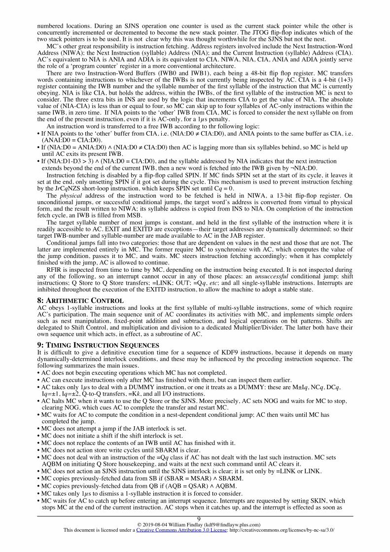
Fetch and Store AC MC EffectS36 Direct Fetch:
EaMq, EaMqQ2 6 (3.5µs);
7 with Q↓ [a+Mq] With Q: Mq := Mq + Iq; Cq := Cq – 1
S37 Indirect Fetch: MkMq, MkMqQ,MkMqN, MkMqQN,MkMqH, MkMqQH,MkMqHN, MkMqQHN
2 7 (4.5µs); 8 with Q
↓ [Mk+Mq] With Q: Mq := Mq + Iq; Cq := Cq – 1Halfword Mq with H,[(1+Mk)+Mq] accessed with N.
S38 Direct Store:= EaMq, = EaMqQ
1 6 (1.5µs); 7 with Q
↑ [a+Mq] With Q: Mq := Mq + Iq; Cq := Cq – 1
S39 Indirect Store: =MkMq, =MkMqQ, =MkMqN, =MkMqQN, =MkMqH, =MkMqQH, =MkMqHN, =MkMqQHN
1 7 (1.5µs); 8 with Q
↑ [Mk +Mq]With Q: Mq := Mq + Iq; Cq := Cq – 1 Halfword Mq with H,[(1+Mk)+Mq] accessed with N.
KEY: a is a main store address
I/O AC MCS40 Peripheral Read 1 TLOQq:
15+tPMHQq, CLOQq:16+tPIxQq, POxQq:22+t, but:15 if unallocated (LIV)17 if device busy18 if uncleared parity error20 if LOV interrupt
S41 Peripheral Write 1
S42 Peripheral Gap 1 MGAPQq/POEQq, MWIPEQq/POFQq:19, but:14 if unallocated (LIV),16 if device busy17 if uncleared parity error19 if LOV interrupt
S43 Peripheral Skip 1 MFSKQq/PMAQq, MRWDQq/PMDQq, MBSKQq/PMEQq: as S42
S44 Peripheral Status 1 INTQq:12, but:11 if unallocated (LIV)13 if device busy BUSYQq, CTQq:13, but:11 if unallocated (LIV)13 if device busy PARQq, MBTQq/PMBQq, MLBQq/PMCQq, METQq/PMFQq:14, but:11 if unallocated (LIV)
13 if device busy
KEY: t = ⎡(Mq – Iq) ÷ 32⎤ is the time taken setting the lock-out store;and PIxQq, POxQq take an additional 6µs core cycle per character or word, depending on the I/O device type
© 2019-08-04 William Findlay ([email protected])This document is licensed under a Creative Commons Attribution 3.0 License: http://creativecommons.org/licenses/by-nc-sa/3.0/
13

I/O DescriptionS40 TLOQq Test Lock-OutS40 CLOQq Clear Lock-Out (Director-only)S40 PIAQq Read Forward S40 PIBQq Read Forward to End-MessageS40 PICQq Read {Character (Paper Tape, Cards), from Fixed Heads (Disc)}S40 PIDQq Read {Character (Paper Tape, Cards), from Fixed Heads (Disc)}
to End-MessageS40 PIEQq Read {Backward (Mag. Tape), Alphanumeric (Cards), Next Sector (Disc)}S40 PIFQq Read {Backward (Mag. Tape), Alphanumeric (Cards); Next Sector (Disc)}
to End-Message??? PIGQq Read {Alphanumeric Character (Cards), Next Sector from Fixed Heads (Disc)}??? PIHQq Read {Alphanumeric Character (Cards), Next Sector from Fixed Heads (Disc)}
to End-MessageS41 POAQq WriteS41 POBQq Write to End-MessageS41 POCQq Write {Last block (Mag. Tape), Character (Paper Tape, Cards), to Fixed Heads
(Disc)}S41 PODQq Write {Last block (Mag. Tape), Character (Paper Tape, Cards), to Fixed Heads
(Disc)}to End-Message
S42 POEQq Write gap on output (magnetic- or paper-) tapeS42 POFQq Wipe long gap on magnetic tape??? POGQq Write {Alphanumeric (Cards), Next Sector (Disc)}??? POHQq Write {Alphanumeric (Cards), Write Sector (Disc)}
to End-Message??? POKQq Write {Alphanumeric Character (Cards), Next Sector to Fixed Heads (Disc)}
to End-Message??? POLQq Write {Alphanumeric Character (Cards), Next Sector to Fixed Heads (Disc)}S43?
INTQq Interrupt if device is busy (Director Entry)— may be S44?
S43 PMAQq Forward Skip (Mag. Tape), Seek (Disc)S43 PMDQq Rewind (Mag. Tape), Home Heads (Disc)S43 PMEQq Backward Skip (Mag. Tape)S44 CTQq Clear any extant Transfer and set device unready/offline (Director-only)S44 MANUALQq Set device offline/unreadyS44 PARQq Test for Parity-Check or other device errorS44 BUSYQq Test for Busy deviceS44 PMBQq Test for Beginning of Tape window (Mag. Tape)S44 PMCQq Test for Last BlockS44 PMFQq Test for End of Tape Warning (Mag. Tape), Test for End of Area (Disc)??? PMGQq Read C-Store (Director-only)??? PMHQq Set Lock-Out (Director-only)??? PMKQq Forward Skip, even parity, on IBM tape??? PMLQq Backward Skip, even parity, on IBM tape
Interrupts AC MC EffectS45 OUT 2 3 (2.5µs) System-call: ⇓ CIA; enter
Director stateLOV 2 3 (2.5µs) ⇓ CIA; enter Director stateOthers 2 3 (2.5µs) ⇓ NIA; enter Director state
© 2019-08-04 William Findlay ([email protected])This document is licensed under a Creative Commons Attribution 3.0 License: http://creativecommons.org/licenses/by-nc-sa/3.0/
14

‘arithmetic’, all S46 AC Effect {MC takes 0µs, or 1µs if too far ahead of AC}+, – 1 r, l : I; ↑ r, l; ↓ l ± rABS 1 r: I; ↑ r; ↓ | r |DUMMY 1 ‘No-op’ERASE, REV 1 Reorder top of nest: see §2.3.NEG 1 r: I; ↑ r; ↓ –rNOT 1 r: W; ↑ r; ↓ ¬ rAND, OR 1 r, l : W; ↑ r, l; ↓ l ∧ r {but for OR: ↓ l ∨ r}ROUND 1 r: D; ↑ r; ↓ (r rounded to I)VR 1 Clear Overflow=TR 2 ↑ l; if l < 0 then set Test Register endCONT 2 r: D; ↑ r; ↓ (r contracted to I)DUP, CAB, PERM, ZERO
2 Reorder top of nest: see §2.3.
NEGD 2 r: D; ↑ r; ↓ –rNEV 2 r, l : W; ↑ r, l; ↓ l ≢ r {Not Equivalent, i.e., exclusive or}ROUNDH 2 r: I; ↑ r; ↓ (r rounded to H) {D24-D47 of result are undefined}+D, –D 3 r, l : D; ↑ r, l; ↓ l ± rNEGF 3 r: F; ↑ r; ↓ –rROUNDF 3 r: DF; ↑ r; ↓ (r rounded to F)ROUNDHF 3 r: F; ↑ r; ↓ (r rounded to FH) {D24-D47 of result are undefined}SIGN 3 r, l : I; ↑ r, l; ↓ if l > r then +1 elsif l < r then –1 else 0 endSTR 3 r: I; ↑ r; ↓( r stretched to D): D0-D47 of result = r:D0, D48 = 0ABSF 4 r: F; ↑ r; ↓ | r | {ABSF takes only 1µs if r ≥ 0}DUPD, REVD 4 Reorder top of nest: see §2.3.MAX 4 r, l : I; ↑ r, l; if l ≥ r then ↓ r, l; set Overflow else ↓ l, r endSIGNF 5 r, l : F; ↑ r, l; ↓ if l > r then +1 elsif l < r then –1 else 0 endSTAND 5+n r: F; ↑ r; ↓ (r normalised)FIX 6 r : F; y, x : I; ↑ r; ↓ y, x: r = y × 2x, –1 ≤ y <+1MAXF 6 r, l : F; ↑ r, l; if l ≥ r then ↓ r, l; set Overflow else ↓ l, r endFLOAT 7+n x : F; r, l : I; ↑ r, l; ↓ x = l × 2r: –128 ≤ r ≤ +127+F, –F 7+a+n r, l : F; ↑ r, l; ↓ l ± rFLOATD 8+n x : DF; r : I; l : D; ↑ r, l; ↓ x = l × 2r, unrounded: –128 ≤ r ≤ +127NEGDF 9+n r: DF; ↑ r; ↓ –r, unrounded+DF, –DF 12+a+n ∆ r, l : DF; ↑ r, l; ↓ l ± r, unrounded×D 14 r, l : I; x : D; ↑ r, l; ↓ x = l × r× 15 r, l : I; x : D; ↑ r, l; ↓ D0-D47 of (x = l × r), rounded×F 15+n r, l, x : F; ↑ r, l; ↓ x = l × r×DF 16+n r, l : F; x : DF; ↑ r, l; ↓ x = l × r, unrounded×+F 18+a+n r, l : F; x, s : DF; ↑ r, l; ↑ s; ↓ x = l × r + s, unroundedBITS 27 r : W; x : I; ↑ r; ↓ x = # of 1-bits in r÷F 35+n r, l, x : F; ↑ r, l; ↓ x = l ÷ r, unrounded÷DF 36+n x, r : F; l : DF; ↑ r, l; ↓ x = l ÷ r, unrounded÷ 36+a+n x, r, l : I; ↑ r, l; ↓ x = l ÷ r, rounded: –1 ≤ x <+1÷D 36+a+n x, r : I; l : D; ↑ r, l; ↓ x = l ÷ r, rounded: –1 ≤ x <+1÷I 36+a+n d, n, q, r : I; ↑ d; ↑ n; ↓ q, r: n = d × q + r, |r| < |d|, rd > 0÷R 36+a+n f, x, r : I; l : D; ↑ r, l; ↓ f, x: l = r × x + 2–47f, –1 ≤ x < +1TOB ≃ 2+4b r, l : W; b: I; ↑ r, l; ↓ b = r converted to binary using radixes l
FRB ≃ 8+3b r : I; l, c : W; ↑ r, l; ↓ c = r converted from binary using radixes l
KEY: a is shifting time in excess of 1µs needed to align the operandsn is shifting time in excess of 1µs needed to produce a normalized resultb is the number of 1 bits in the numerical operand∆ denotes a “variable time” instruction, whose timing depends on which operand has the larger exponent
© 2019-08-04 William Findlay ([email protected])This document is licensed under a Creative Commons Attribution 3.0 License: http://creativecommons.org/licenses/by-nc-sa/3.0/
15

APPENDIX 2: KDF9 INSTRUCTION SET ENCODINGOperand coding symbols:a A main store word address bitb A non-decoded “don’t care” bit—should be set to 0h A halfword is to be added to the return address if h = 0i A bit of a 16-bit constantkkkk, qqqq Q Store register numbers (0..15)sss A instruction syllable number in 0..5; 6 and 7 invalidu Device is set unready on completion of operation
The first column gives the identifier of the MC microcode sequence that carries out the instruction.
Instruction \ Bits: 0,1 2,3 4 5-7 8-11 12-15 16-23
S1 JSr 10 00 a sss 1101 aaaa aaaaaaaaS2 JrCqZ 10 10 a sss qqqq aaaa aaaaaaaaS2 JrCqNZ 10 11 a sss qqqq aaaa aaaaaaaaS3 Jr 10 00 a sss 1011 aaaa aaaaaaaaS4 JrCqNZS 01 11 1 111 qqqq bbbbS5 Jr= 10 01 a sss 0001 aaaa aaaaaaaaS5 Jr≠ 10 00 a sss 0001 aaaa aaaaaaaaS6 Jr>Z 10 01 a sss 0100 aaaa aaaaaaaaS6 Jr≤Z 10 00 a sss 0100 aaaa aaaaaaaaS6 Jr<Z 10 01 a sss 0010 aaaa aaaaaaaaS6 Jr≥Z 10 00 a sss 0010 aaaa aaaaaaaaS6 Jr=Z 10 01 a sss 0110 aaaa aaaaaaaaS6 Jr≠Z 10 00 a sss 0110 aaaa aaaaaaaaS7 JrV 10 01 a sss 1000 aaaa aaaaaaaaS7 JrNV 10 00 a sss 1000 aaaa aaaaaaaaS7 JrEN 10 01 a sss 1010 aaaa aaaaaaaaS7 JrNEN 10 00 a sss 1010 aaaa aaaaaaaaS7 JrEJ 10 01 a sss 1100 aaaa aaaaaaaaS7 JrNEJ 10 00 a sss 1100 aaaa aaaaaaaaS7 JrTR 10 01 a sss 1110 aaaa aaaaaaaaS7 JrNTR 10 00 a sss 1110 aaaa aaaaaaaaS8 EXIT 10 00 a 0h0 1111 aaaa aaaaaaaaS9 EXITD 10 01 0 010 1111 0000 00000000
S10 LINK 01 11 1 011 0000 bbbbS11 =LINK 01 11 1 100 0000 bbbb
S12 M+Iq 01 10 0 000 qqqq bbbbS13 M–Iq 01 10 0 001 qqqq bbbbS14 NCq 01 10 0 010 qqqq bbbbS15 DCq 01 10 0 011 qqqq bbbbS16 Iq=1 01 10 0 100 qqqq bbbbS17 Iq=–1 01 10 0 101 qqqq bbbbS18 Iq=2 01 10 0 110 qqqq bbbbS19 Iq=–2 01 10 0 111 qqqq bbbbS20 MkTOQq 01 10 1 001 kkkk qqqqS20 IkTOQq 01 10 1 010 kkkk qqqqS20 IMkTOQq 01 10 1 011 kkkk qqqqS20 CkTOQq 01 10 1 100 kkkk qqqqS20 CMkTOQ
q01 10 1 101 kkkk qqqq
S20 CIkTOQq 01 10 1 110 kkkk qqqqS20 QkTOQq 01 10 1 111 kkkk qqqq
S21 Qq 01 11 1 001 qqqq 111bS22 Cq 01 11 1 001 qqqq 100bS23 Iq 01 11 1 001 qqqq 010bS24 Mq 01 11 1 001 qqqq 001b
S25 SET 11 bb b 1b0 iiii iiii iiiiiiii
© 2019-08-04 William Findlay ([email protected])This document is licensed under a Creative Commons Attribution 3.0 License: http://creativecommons.org/licenses/by-nc-sa/3.0/
16
S26 =Qq 01 11 1 000 qqqq 1110S26 =Cq 01 11 1 000 qqqq 1000S26 =Iq 01 11 1 000 qqqq 0100S26 =Mq 01 11 1 000 qqqq 0010S27 =RCq 01 11 1 000 qqqq 1001S27 =RIq 01 11 1 000 qqqq 0101S27 =RMq 01 11 1 000 qqqq 0011S28 =+Qq 01 11 1 010 qqqq 111bS29 =+Cq 01 11 1 010 qqqq 100bS30 =+Iq 01 11 1 010 qqqq 010bS31 =+Mq 01 11 1 010 qqqq 001b
S32 SHA±n 01 11 0 001 nnnn nnn1
S32 SHAD±n 01 11 0 010 nnnn nnn1
S32 ×+±n 01 11 0 011 nnnn nnn1
S32 SHL±n 01 11 0 100 nnnn nnn1
S32 SHLD±n 01 11 0 110 nnnn nnn1
S32 SHC±n 01 11 0 111 nnnn nnn1
S33 SHACq 01 11 0 001 qqqq bbb0
S33 SHADCq 01 11 0 010 qqqq bbb0
S33 ×+Cq 01 11 0 011 qqqq bbb0
S33 SHLCq 01 11 0 100 qqqq bbb0
S33 SHLDCq 01 11 0 110 qqqq bbb0
S33 SHCCq 01 11 0 111 qqqq bbb0
S34 =K0 01 11 1 101 1000 0000S34 =K1 01 11 1 101 0100 0000S34 =K2 01 11 1 101 0010 0000S34 =K3 01 11 1 101 0001 0000S35 K4 01 11 1 110 0000 1000S35 K5 01 11 1 110 0000 0100S35 K7 01 11 1 110 0000 0001
S36 EaMq 11 aa a 000 qqqq aaaa aaaaaaaaS36 EaMqQ 11 aa a 010 qqqq aaaa aaaaaaaa
S37 MkMq 01 00 0 000 qqqq kkkk
S37 MkMqQ 01 00 0 010 qqqq kkkk
S37 MkMqH 01 00 0 100 qqqq kkkk
S37 MkMqQH 01 00 0 110 qqqq kkkk
S37 MkMqN 01 00 1 000 qqqq kkkk
S37 MkMqQN 01 00 1 010 qqqq kkkk
S37 MkMqHN 01 00 1 100 qqqq kkkk
S37 MkMqQHN 01 00 1 110 qqqq kkkk
S38 =EaMq 11 aa a 001 qqqq aaaa aaaaaaaaS38 =EaMqQ 11 aa a 011 qqqq aaaa aaaaaaaa
© 2019-08-04 William Findlay ([email protected])This document is licensed under a Creative Commons Attribution 3.0 License: http://creativecommons.org/licenses/by-nc-sa/3.0/
17

S39 =MkMq 01 00 0 001 qqqq kkkk
S39 =MkMqQ 01 00 0 011 qqqq kkkk
S39 =MkMqH 01 00 0 101 qqqq kkkk
S39 =MkMqQH 01 00 0 111 qqqq kkkk
S39 =MkMqN 01 00 1 001 qqqq kkkk
S39 =MkMqQN 01 00 1 011 qqqq kkkk
S39 =MkMqHN 01 00 1 101 qqqq kkkk
S39 =MkMqQHN 01 00 1 111 qqqq kkkk
S40 CLOQq 01 01 0 100 qqqq 001uS40 TLOQq 01 01 0 100 qqqq 010uS40 PIA MFRQq 01 01 0 100 qqqq 000uS40 PIB MFREQq 01 01 0 101 qqqq 000uS40 PIC RCQq 01 01 0 100 qqqq 100uS40 PID RCEQq 01 01 0 101 qqqq 100uS40 PIE MBRQq 01 01 0 110 qqqq 000uS40 PIF MBREQq 01 01 0 111 qqqq 000u??? PIG PIGQq 01 01 0 110 qqqq 100u??? PIH PIHQq 01 01 0 111 qqqq 100u
S41 POA MWQq 01 01 1 000 qqqq 000uS41 POB MWEQq 01 01 1 001 qqqq 000uS41 POC MLWQq 01 01 1 000 qqqq 100uS41 POD MLWEQq 01 01 1 001 qqqq 100uS42 POE MGAPQq 01 01 1 000 qqqq 110uS42 POF MWIPEQq 01 01 1 000 qqqq 010u??? POG POGQq 01 01 1 010 qqqq 000u??? POH POHQq 01 01 1 011 qqqq 000u??? POK POKQq 01 01 1 011 qqqq 100u??? POL POLQq 01 01 1 010 qqqq 100u
S43 INTQq 01 01 1 10b qqqq 0b1uS44 CTQq 01 01 0 000 qqqq 0000S44 MANUALQq 01 01 0 000 qqqq 0001S44 BUSYQq 01 01 0 000 qqqq 001uS44 PARQq 01 01 0 001 qqqq 000uS43 PMA MFSKQq 01 01 1 100 qqqq 000uS44 PMB MBTQq 01 01 0 000 qqqq 100uS44 PMC MLBQq 01 01 0 000 qqqq 010uS43 PMD MRWDQq 01 01 1 110 qqqq 100uS43 PME MBSKQq 01 01 1 110 qqqq 000uS44 PMF METQq 01 01 0 010 qqqq 000u??? PMG fetch C store 01 01 0 010 qqqq 010u??? PMH set lock-out 01 01 1 000 qqqq 001u??? PMK 7T FSK even 01 01 1 100 qqqq 010u??? PML 7T BSK even 01 01 1 110 qqqq 010u
Note: older versions of this document gave incorrect codes for PMG and PMH. These wrong guesses are implemented in versions of ee9 prior to V2.1, and in the versions of kal3 included with those distributions.
S45 OUT 10 00 b bbb 1001 bbbb bbbbbbbb
© 2019-08-04 William Findlay ([email protected])This document is licensed under a Creative Commons Attribution 3.0 License: http://creativecommons.org/licenses/by-nc-sa/3.0/
18

S46 Illegal 00 000000S46 VR 00 000001S46 =TR 00 000010S46 BITS 00 000011S46 ×F 00 000100S46 ×DF 00 000101S46 Unused ? 00 000110S46 ×+F 00 000111S46 NEGD 00 001000S46 OR 00 001001S46 PERM 00 001010S46 TOB 00 001011S46 ROUNDH 00 001100S46 NEV 00 001101S46 ROUND 00 001110S46 DUMMY 00 001111S46 ROUNDF 00 010000S46 ROUNDHF 00 010001S46 –DF 00 010010S46 +DF 00 010011S46 FLOAT 00 010100S46 FLOATD 00 010101S46 ABS 00 010110S46 NEG 00 010111S46 ABSF 00 011000S46 NEGF 00 011001S46 MAX 00 011010S46 NOT 00 011011S46 ×D 00 011100S46 × 00 011101S46 – 00 011110S46 SIGN 00 011111
S46 Illegal 00 100000S46 ZERO 00 100001S46 DUP 00 100010S46 DUPD 00 100011S46 ÷I 00 100100S46 FIX 00 100101S46 Illegal 00 100110S46 STR 00 100111S46 CONT 00 101000S46 REVD 00 101001S46 ERASE 00 101010S46 –D 00 101011S46 AND 00 101100S46 Illegal 00 101101S46 + 00 101110S46 +D 00 101111S46 ÷ 00 110000S46 ÷D 00 110001S46 ÷F 00 110010S46 ÷DF 00 110011S46 ÷R 00 110100S46 REV 00 110101S46 CAB 00 110110S46 FRB 00 110111S46 STAND 00 111000S46 NEGDF 00 111001S46 MAXF 00 111010S46 Illegal 00 111011S46 +F 00 111100S46 –F 00 111101S46 Illegal 00 111110S46 SIGNF 00 111111
© 2019-08-04 William Findlay ([email protected])This document is licensed under a Creative Commons Attribution 3.0 License: http://creativecommons.org/licenses/by-nc-sa/3.0/
19

APPENDIX 3: THE I/O INSTRUCTIONSIn the following tables, blank cells are to be taken as inheriting the common semantics. Where something is shown in acell it overrides the common semantics.
INPUT INSTRUCTIONS
PIA PIB PIC PID PIE PIF PIG PIH
common R RE CR CRE =PIA =PIB =PIC =PID
CR BR BRE CBR CBRE AR ARE CAR CARE
DR R RE =PIA =PIB =PIA =PIB
FD FR FRE RN RNE FRN FRNE
MT EE =PIA =PIB <R <RE =PIE =PIF
MT IBM OR VR =PIA =PIB O<R V<R =PIE =PIF
SI XR XRE
TR
FW
OUTPUT INSTRUCTIONS
POA POB POC POD POE POF POG POH POK POL
common W WE CW CWE LIV LIV UND UND UND UND
CP BW BWE CBW CBWE =POC =POA AW AWE CAWE CAW
DR =POA =POB WZ =POE
FD FW FWE =POC =POA WN WNE FWNE FWE
GP =POA =POC NOP NOP
LP ??? ??? ??? ??? ??? ???
MT EE WL WLE GAP WIPE
MT IBM OW VW OT VT GAP WIPE
SI CGAP WGAP
TP CGAP WGAP
FW
DEVICE CONTROL INSTRUCTIONS
PMA PMB PMC PMD PME PMF PMG PMH PMK PML
common LIV NOP NOP LIV LIV NOP RCS SLO UND UND
CP
CR TRC?
DR
FD S P UND EOA?
GP GPA?
LP
MT EE >> BOT? LBL? <<< << ETW?
MT IBM O>> BOT? LBL? <<< O<< ETW? V>> V<<
SI T8T? T8T?
TP GPA?
TR T8T?
FW
© 2019-08-04 William Findlay ([email protected])This document is licensed under a Creative Commons Attribution 3.0 License: http://creativecommons.org/licenses/by-nc-sa/3.0/
20

KEY:common these effects are common to all devices, unless over-ridden by a specific table entryCP card punchCR card readerDR drum storeFD fixed disc storeGP graph plotterLP line printerMT EE EE magnetic tape deckMT IBM IBM-compatible 7-track magnetic tape deckSI standard interface bufferTP paper tape punchTR paper tape readerFW Flexowriter monitor typewriter
A alphanumeric (converted to/from all 12 card rows in each column)B binary (direct to/from 6 card rows, twice in each column)C character (each character transferred is stored in the least significant 6 or 8 bits of a word)E stopping on an End Message characterF using the fixed headsN next sectorO in odd parityP clear disc head positionsR readS seek disc headsT write tape markV in even parityX without parity< backward (for read operation)>> forward skip up to Mq blocks<< backward skip up to Mq blocks<<< rewind the tape to before its first block
=Pxy having the same effect as the Pxy order for this device
CGAP punch a gap of length Mq / 10 inchesWGAP punch a gap? (‘word gap’; undocumented)GAP erase an inter-block gap of Mq wordsWIPE erase a bigger inter-block gap than GAP
BOT? Test Register := tape at Beginning Of Tape windowEOA? Test Register := disc transfer reached end of areaETW? Test Register := tape at End Tape WarningGPA? Test Register := a graph plotter is attached to the buffer and not a tape punchLBL? Test Register := tape at Last Block markerT8T? Test Register := device in 8-channel modeTRC? Test Register := recheck switch is set on the card reader
RCS Director-only (LIV caused in program mode): ‘read C store’SLO Director-only (LIV caused in program mode): ‘set lock-outs’LIV Lock-In Violation (always)NOP no operationUND ‘undefined’??? undocumented
© 2019-08-04 William Findlay ([email protected])This document is licensed under a Creative Commons Attribution 3.0 License: http://creativecommons.org/licenses/by-nc-sa/3.0/
21

APPENDIX 4: THE KDF9 CHARACTER SETS AND CODES
Line printer SP NLC CRLF/LS FF/PC NLC NLC % 'Normal Case SP NLC CRLF/LS FF/PC HT NLC CS CNShift Case SP NLC CRLF/LS FF/PC HT NLC CS CNCard rows none Y68 Y28 028 058 Y58 048 Y78Octal code 00 01 02 03 04 05 06 07
Line printer : = ( ) £ * , /Normal Case NLC NLC NLC NLC NLC NLC NLC /Shift Case NLC NLC NLC NLC NLC NLC NLC :Card rows 48 38 X58 X28 X38 X48 038 01Octal code 10 11 12 13 14 15 16 17
Line printer 0 1 2 3 4 5 6 7Normal Case 0 1 2 3 4 5 6 7Shift Case ↑ [ ] < > = × ÷Card rows 0 1 2 3 4 5 6 7Octal code 20 21 22 23 24 25 26 27
Line printer 8 9 NLC 10 ; + - .Normal Case 8 9 10 ; + - .Shift Case ( )
£ ; ≠ * ,
Card rows 8 9 068 X68 Y48 Y X Y38Octal code 30 31 32 33 34 35 36 37
Line printer NLC A B C D E F GNormal Case NLC A B C D E F GShift Case NLC a b c d e f gCard rows 078 Y1 Y2 Y3 Y4 Y5 Y6 Y7Octal code 40 41 42 43 44 45 46 47
Line printer H I J K L M N ONormal Case H I J K L M N OShift Case h i j k l m n oCard rows Y8 Y9 X1 X2 X3 X4 X5 X6Octal code 50 51 52 53 54 55 56 57
Line printer P Q R S T U V WNormal Case P Q R S T U V WShift Case p q r s t u v wCard rows X7 X8 X9 02 03 04 05 06Octal code 60 61 62 63 64 65 66 67
Line printer X Y Z NLC NLC NLC NLC ØNormal Case X Y Z NLC NLC NLC ØShift Case x y z NLC NLC NLC ØCard rows 07 08 09 58 68 78 X78 28Octal code 70 71 72 73 74 75 76 77
KEY: SP is (blank) Space; CRLF is Carriage Return Line Feed (i.e. New Line); PC is Page Change (i.e. Form Feed); HT isHorizontal Tab; CS is Case Shift; CN is Case Normal. NLC indicates a non-legible character (always suppressed by theline printer); and Ø represents the filler character, suppressed by all legible output devices in normal transfer modes.
The underline ‘ ’ does not advance the Flexowriter carriage and so is over-printed by the following character; it isused to represent Algol 60 ‘publication language’ basic symbols, e.g., ‘begin’, as ‘begin’.
The ‘10’ is the single-character exponent delimiter used in Algol 60’s real number syntax.Punched cards have 80 columns of 12 rows. Rows 0-9 represent the decimal digits with a single punched hole. The
other two rows are called X, above 0, and Y, at the top (on some non-KDF9 systems these are known as 11, just above0, and 12 or 10 at the top). Most non-numeric characters are represented by combinations of two or three holes, onefrom rows Y, X, or 0, and the others in rows 1 through 8.
© 2019-08-04 William Findlay ([email protected])This document is licensed under a Creative Commons Attribution 3.0 License: http://creativecommons.org/licenses/by-nc-sa/3.0/
22

APPENDIX 5: THE KDF9 GRAPH PLOTTER CODES
Action Decimal Octal Binary
None 0 #0 000000
Step paper backwards 1 #1 000001
Step paper forwards 2 #2 000010
Step pen right 4 #4 000100
Step pen right, paper backwards 5 #5 000101
Step pen right, paper forwards 6 #6 000110
Step pen left 8 #10 001000
Step pen left, paper backwards 9 #11 001001
Step pen left, paper forwards 10 #12 001010
Lower pen 16 #20 010000
Raise pen 32 #40 100000
All other 6-bit character codes represent invalid plotter commands. It is confidently assumed that the plotter command codes in [EEC69] Appendix 6, §5, p.302 are wrong, as there is anobvious error whereby 11 plotting codes are claimed but only 9 are given, the last of them being inconsistent with theothers. The codes listed above have been confirmed by the evidence of other computers that used the same plotter.
REFERENCES AND BIBLIOGRAPHY
[Davis60] The English Electric KDF9 Computer System; G.M. Davis;BCS Computer Bulletin, Vol. 4 No. 3; 1960.
[EEC62a] KDF9: Basic Organisation of Controls; and Instruction Timings; J.R. Lucking and J.P. O’Neil;Report K/GD.y.73, The English Electric Company Limited; 9 July 1962.
For the above document, see: www.findlayw.plus.com/KDF9/Documents
[EEC62b] Notes on KDF 9 Main Control; J.A. Edwards;Report K/GD.u.293, The English Electric Company Limited; 7 September 1962.
[EEC62c] KDF 9—Transformer Sequence Units; J.R. Lucking;Report K/GD.y.81, The English Electric Company Limited; 15 November 1962.
For the above two documents, see: sw.ccs.bcs.org/KDF9/Wichmann/techdoc.html
[ICL69] KDF9 Programming ManualPublication 1003 mm, 2nd Edition, International Computers Limited; October 1969.
[Findlay18] The English Electric KDF9; W. Findlay; 2018.
[Findlay19a] The Software of the KDF9; W. Findlay; 2019.
[Findlay19b] Users’ Guide for ee9: An English Electric KDF9 Emulator; W. Findlay; 2019.
[Findlay19c] Benchmarking and the KDF9; W. Findlay; 2019.
[Findlay19d] A KDF9 Bibliography; W. Findlay; 2019.
For the above five documents, see: www.findlayw.plus.com/KDF9/Documents
[Haley62] The KDF9 Computer System; A.C.D. Haley;Proceedings of the Fall Joint Computer Conference, AFIPS Conference Proceedings, Vol.22; 1962.
[Longbottom]<www.webarchive.org.uk/wayback/archive/20130303230703/www.roylongbottom.org.uk/whetstone.htm>
Roy Longbottom.
[UofI58] On the Design of a Very High-Speed Computer;
Report No. 80 2nd Edition, University of Illinois Graduate College Digital Computer Laboratory; April 1958.
For the above document, see:
bitsavers.trailing-edge.com/pdf/univOfIllinoisUrbana/illiac/ILLIAC_II
[WR67] Competition for memory access in the KDF9; C.S. Wallace and B.G. Rowswell;Computer Journal, Vol.10, pp. 64-68; 1967.
© 2019-08-04 William Findlay ([email protected])This document is licensed under a Creative Commons Attribution 3.0 License: http://creativecommons.org/licenses/by-nc-sa/3.0/
23


![DihydroceramideDesaturaseInhibitionbyaCyclopropanated ...downloads.hindawi.com/journals/jl/2011/724015.pdfbut also for those of sphingosine-1-phosphate (review: [12]). Dihydroceramide](https://img.pdfslide.us/doc/110x75/60291fd8cdc0c448707e1227/dihydroceramidedesaturaseinhibitionbyacyclopropanated-but-also-for-those-of.jpg)