Embed Size (px)
Citation preview
The Hand-bot, a Robot Design for SimultaneousClimbing and Manipulation
Michael Bonani, Stephane Magnenat, Philippe Retornaz, and FrancescoMondada
Michael BonaniEPFL-LSRO, Station 9, CH-1015 Lausanne
http://mobots.epfl.ch/
Abstract. We present a novel approach to mobile object manipulationfor service in indoor environments. Current research in service roboticsfocus on single robots able to move, manipulate objects, and transportthem to various locations. Our approach differs by taking a collective ro-botics perspective: different types of small robots perform different tasksand exploit complementarity by collaborating together. We propose arobot design to solve one of these tasks: climbing vertical structuresand manipulating objects. Our robot embeds two manipulators that cangrasp both objects or structures. To help climbing, it uses a rope to com-pensate for the gravity force. This allows it to free one of its manipulatorsto interact with an object while the other grasps a part of a structure forstabilization. Our robot can launch and retrieve the rope autonomously,allowing multiple ascents. We show the design and the implementationof our robot and demonstrate the successful autonomous retrieval of abook from a shelf.
1 Introduction
Service robotics has a large economic potential [1]. In its applications, if robust-ness and flexibility are dominant requirements, collective robotics is a promis-ing paradigm [2, 3]. Because collective robotics distributes the work to multi-ple robots, it requires different control, more hardware units, and usually moreengineering resources than the approaches based on single robots [4]. Yet thephysical redundancy between the robots enables a high availability. Moreover,their modularity provides adaptation to changing needs and situations. Theseunique features might outstrip the drawbacks of collective robotics eventually.
To implement service robotics tasks successfully, groups of robots must beable to manipulate objects in the environment. These objects can be located inaltitude, and robots part of a collective are small. Therefore, these robots mustbe able to climb the environment to fetch the objects. This paper proposes adesign concept and demonstrates a working implementation of a climbing robotthat performs manipulation tasks.
In a heterogeneous group, as proposed by the Swarmanoid project [5], ourrobot is only responsible for manipulation of objects in altitude. While on thefloor, it relies on other types of robots for mobility. These robots would havedifferent hardware, in particular, they would be able to self-assemble with ourrobot and move it on the ground [6]. Such task and hardware specializationallows the best use of the capabilities of each type of robots while self-assemblingprovides the synergy to compensate for the limitations of each individual type.
2 State of the art
The ascension of vertical surfaces is a difficult problem: it requires a lightweightrobot with strong actuators, which results in a sensitive mechatronic design.For this reason, few systems combine the abilities of climbing and manipula-tion. Researchers in the field of space manipulators —where robots move inmicrogravity— have already studied this combination [7].
Some robots require an adaptation of the environment, such as in [8] wherethe robot needs custom-tailored docks to attach. To remove this limitation, sev-eral works have explored vacuum adhesion. For instance, [9] proposes a medium-size robot (diameter of 50 cm) for inspection of large surfaces. A vacuum systemprovides the adhesion force while three wheels allow the robot to move on thesurface. To scan the surroundings of the robot, an inspection sensor is attachedto a parallel arm. This system does not allow manipulation of external objects.
The Alicia3 [10] is a larger robot (length of 1.3 m, weight of 20 kg) whichalso uses pressure for adhesion. It consists of three attachment units linked by anarticulated arm. Each unit contains its own vacuum generator and displacementwheels. Although the design of this robots is focused on climbing, its arm-basedstructure could support manipulation capabilities.
Several authors have proposed large platforms for outdoor operations onbuildings or industrial superstructures [11], often for specific applications [12].These platforms could support the addition of manipulators; however their sizemakes them unsuitable for the type of application we consider.
There exist several robots that utilize some form of grasping to climb [13–15]. Their grippers are custom-tailored to specific structures. Yet none of theserobots can use their grippers to perform object manipulation.
To the best of our knowledge there is no small autonomous robot (few decime-ters cube) that implements a combination of climbing and object manipulation.
3 Design and implementation
We propose a novel approach to mobile object manipulation for service in in-door environments. It takes advantage of synergies between climbing and objectmanipulation. This translates as the ability to climb common vertical officesstructures such as shelves. Within these structures, the robot gets small objectssuch as lightweight books or compact discs. It then retrieves these objects to
f
a
e
d
c
g
b
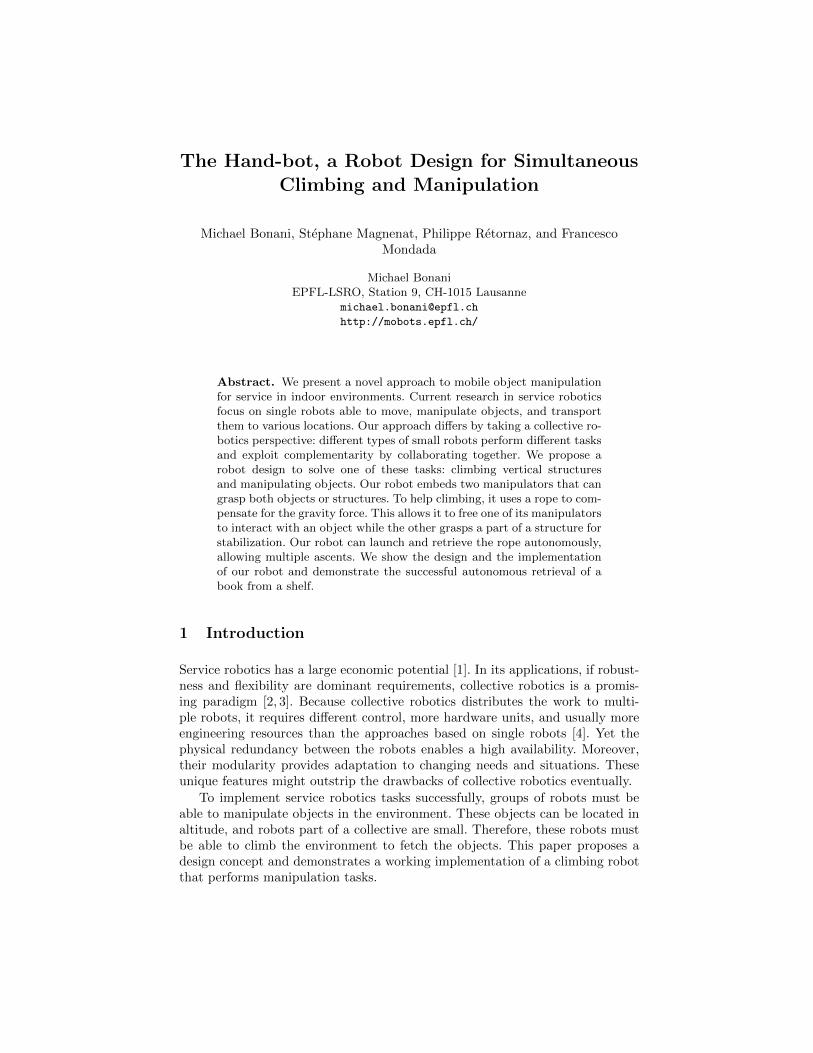
hFig. 1: Overview of the hand-bot. a: The body, containing inparticular the battery, the ropelauncher, and the head rotationmotor. b: The tube of the ropelauncher. c: The head, contain-ing the two arms bending mo-tors. d: The arms. e: The grip-pers, each containing two motorsfor rotation and grasping. f: Twofan to control the yaw when hand-bot hangs at the rope. g: Connec-tion ring. h: Switchable magnet.
the ground and brings them to a specific location. We have implemented thisapproach in the hand-bot (Fig. 1) robot that we present in this article.
The biggest constraint for climbing under gravity is to provide the verticallift force; we thus implement climbing by combining two techniques. Rolling arope provides the vertical lift force while manipulators provide horizontal oper-ations. The hand-bot fixes the rope to a ceiling and coils it around a reel. Thismechanism is simple and can lift a large mass by using a strong motor; as shownby previous work [16]. To be autonomous, the robot must be able to attach itsrope to a specific location, use it to climb, and retrieve it afterwards. We pro-pose a launching mechanism based on a strong spring (Fig. 1b) that projects amagnet to the ceiling. Albeit this approach works only in environments with aferromagnetic ceiling, it is well understood and reliable. Moreover, depending onthe type of ceiling, other attachment mechanisms such as plungers are applica-ble. To be able to detach from the ceiling, the attachment must be switchable.We implement this feature using a magnetic switch that the robot can triggerwith a specific infrared transmission.
When attached to the ceiling using the rope, the hand-bot has vertical mobil-ity but is horizontally unstable. To stabilize and position itself on the horizontalplane, it needs manipulators to grasp the structure around it. The hand-bot hastwo arms, each with a gripper as manipulator (Fig. 1d,e). When using the twoarms to climb, it maintains its stability all the time. It can also manipulate anobject with one gripper while keeping the other one attached to the structure.That way, the hand-bot can manipulate objects precisely. Once on the ground,other types of robots can assemble with the hand-bot and displace it and the ob-ject it carries to a specific location. The other robots [5] attach to the hand-botby grasping its translucent ring, which also contains 12 rgb leds.
3.1 Rope launcher
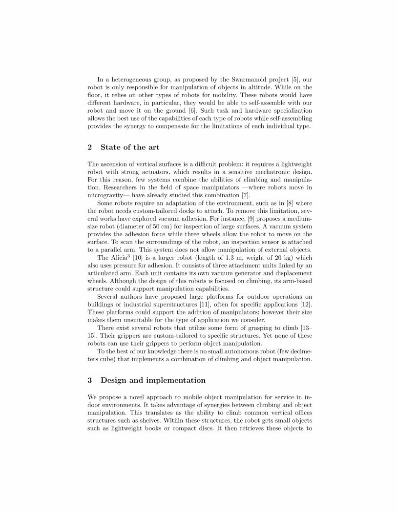
As we explained in the preceding sections, the rope provides the main liftingforce of the hand-bot. Fig. 2a shows a photo of the mechanism of the rope
(a) rope launcher
a cb
(b) rope launching sequence
Fig. 2: (a) Mechanism of the rope launcher. a: The launching tube containinga spring. b: The motor to compress the spring. c: The lifting motor. d: Theservomotor clutch to engage the lifting motor. e: The motor directly connectedto the reel, to coil the rope on magnet retrieval and to provide tension control.(b) Schematics of the launching sequence, filled rectangles show the active motor.a: A motor compresses the spring. b: A fast motor maintains tension in the ropewhile the spring launches the magnet. c: A clutch is engaged to let the strongmotor lift the robot.
launcher and Fig. 2b shows the schematics of the launching sequence. To launchthe rope, a motor compresses a spring using a small wagon. This wagon movesinside the launch tube and is driven by a worm gear. When the spring is fullycompressed (at that point, it applies a force of 110 N), the wagon hits the bottomof the tube and liberates the spring, which launches the rope, the magnet, andthe detachment mechanism up to an altitude of 270 centimeters. Two differentmotors drive the rope: a strong one provides the main lifting force and a fast onecontrols the tension of the rope, during launch and retrieval. To switch betweenthese two motors, a servomotor activates a clutch. During launch, the fast motorbrakes the reel: this is necessary to prevent the formation of knots in the rope.The launching control program monitors the length of the uncoiled rope in realtime. As soon as the magnet reaches the target altitude, the fast motor firmlycoils back, which ensures the tension in the rope. If the magnet fails to attach,this action will coil back most of the rope and the hand-bot will know the resultof the launch. If the launch succeeds, the servomotor engages the clutch so thatthe strong motor drives the rope, and provides the main lifting force for thehand-bot. This force is strong enough to lift the robot by itself.
If the hand-bot hangs freely at the rope, because it holds an object or hasfailed to grasp an element of structure, it can stabilize and orientate itself usingan inertial measurement unit and two fans. The fans are located at the top ofthe body on both side of the rope launcher tube.
3.2 Manipulators
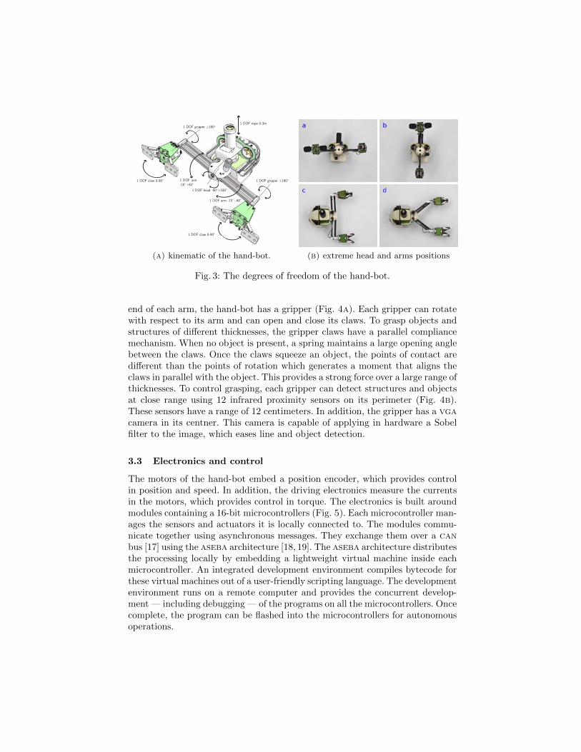
The hand-bot has two arms on its front side. They can bend/extend forward— independently — and rotate with respect to the robot body (Fig. 3). At the
1 DOF gripper ±180°
1 DOF gripper ±180°
1 DOF claw 0-90°
1 DOF claw 0-90°
1 DOF head -90°+180°
1 DOF arm -15°+60°
1 DOF arm -15°+60°
1 DOF rope 0-3m
(a) kinematic of the hand-bot. (b) extreme head and arms positions
Fig. 3: The degrees of freedom of the hand-bot.
end of each arm, the hand-bot has a gripper (Fig. 4a). Each gripper can rotatewith respect to its arm and can open and close its claws. To grasp objects andstructures of different thicknesses, the gripper claws have a parallel compliancemechanism. When no object is present, a spring maintains a large opening anglebetween the claws. Once the claws squeeze an object, the points of contact aredifferent than the points of rotation which generates a moment that aligns theclaws in parallel with the object. This provides a strong force over a large range ofthicknesses. To control grasping, each gripper can detect structures and objectsat close range using 12 infrared proximity sensors on its perimeter (Fig. 4b).These sensors have a range of 12 centimeters. In addition, the gripper has a vgacamera in its centner. This camera is capable of applying in hardware a Sobelfilter to the image, which eases line and object detection.
3.3 Electronics and control
The motors of the hand-bot embed a position encoder, which provides controlin position and speed. In addition, the driving electronics measure the currentsin the motors, which provides control in torque. The electronics is built aroundmodules containing a 16-bit microcontrollers (Fig. 5). Each microcontroller man-ages the sensors and actuators it is locally connected to. The modules commu-nicate together using asynchronous messages. They exchange them over a canbus [17] using the aseba architecture [18, 19]. The aseba architecture distributesthe processing locally by embedding a lightweight virtual machine inside eachmicrocontroller. An integrated development environment compiles bytecode forthese virtual machines out of a user-friendly scripting language. The developmentenvironment runs on a remote computer and provides the concurrent develop-ment — including debugging — of the programs on all the microcontrollers. Oncecomplete, the program can be flashed into the microcontrollers for autonomousoperations.
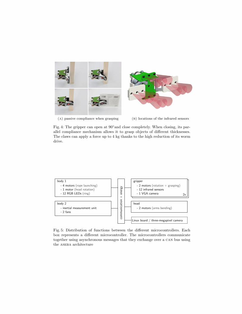
(a) passive compliance when grasping (b) locations of the infrared sensors
Fig. 4: The gripper can open at 90◦and close completely. When closing, its par-allel compliance mechanism allows it to grasp objects of different thicknesses.The claws can apply a force up to 4 kg thanks to the high reduction of its wormdrive.
Fig. 5: Distribution of functions between the different microcontrollers. Eachbox represents a different microcontroller. The microcontrollers communicatetogether using asynchronous messages that they exchange over a can bus usingthe aseba architecture
While the aseba architecture is powerful enough to implement any low-levelautonomous behavior such as climbing a shelf; high level cognitive tasks suchas locating a specific book using vision require more computational power. Tofulfill this need, we will equip the hand-bot with an embedded computer runningLinux, built around an arm 11 processor and 128 MB of ram. This computerwill also provides a Wifi connection and a three-megapixel camera located inthe centner of the head. The experiments that we discuss in the next sectionrun solely using aseba [18]; but the scenarios presented in the introduction willrequire this embedded computer.
3.4 Precision of altitude control
altitude in centimeters
freq
uenc
y
98 99 100 101 102 103
02
46
810
12
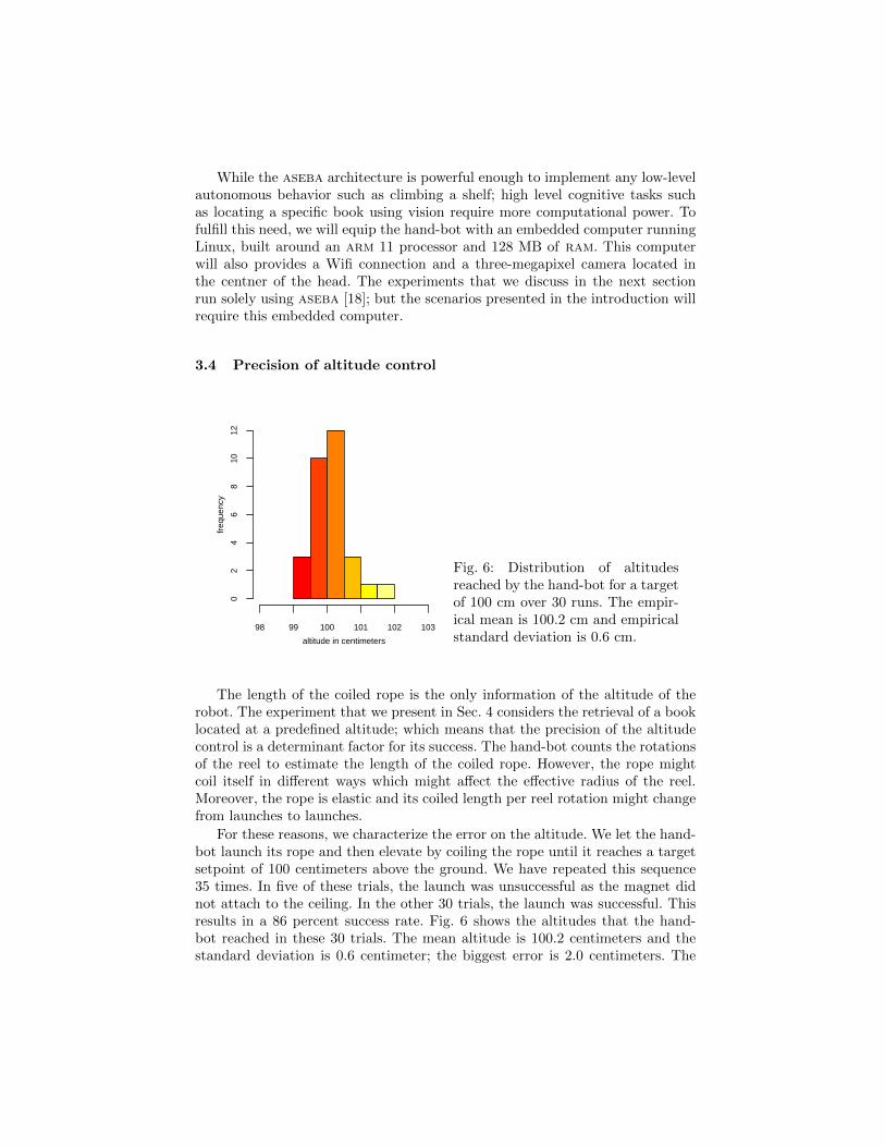
Fig. 6: Distribution of altitudesreached by the hand-bot for a targetof 100 cm over 30 runs. The empir-ical mean is 100.2 cm and empiricalstandard deviation is 0.6 cm.
The length of the coiled rope is the only information of the altitude of therobot. The experiment that we present in Sec. 4 considers the retrieval of a booklocated at a predefined altitude; which means that the precision of the altitudecontrol is a determinant factor for its success. The hand-bot counts the rotationsof the reel to estimate the length of the coiled rope. However, the rope mightcoil itself in different ways which might affect the effective radius of the reel.Moreover, the rope is elastic and its coiled length per reel rotation might changefrom launches to launches.
For these reasons, we characterize the error on the altitude. We let the hand-bot launch its rope and then elevate by coiling the rope until it reaches a targetsetpoint of 100 centimeters above the ground. We have repeated this sequence35 times. In five of these trials, the launch was unsuccessful as the magnet didnot attach to the ceiling. In the other 30 trials, the launch was successful. Thisresults in a 86 percent success rate. Fig. 6 shows the altitudes that the hand-bot reached in these 30 trials. The mean altitude is 100.2 centimeters and thestandard deviation is 0.6 centimeter; the biggest error is 2.0 centimeters. The

altitude control using the rope is thus precise enough to climb to a target altitudeand retrieve an object.
3.5 Workspace
top view
2Lc
βrβl
La
back view
α
h
x
z
xr,zr
xl,zl
xc,zc
ll = Lc + La cos(βl) lr = Lc + La cos(βr) xr = 0 zr = h− lr sin(α)
xl = xr − (ll + lr) cos(α) zl = zr − (ll + lr) sin(α) xc = lr cos(α) zc = h
Fig. 7: Equations of the positions of the grippers given the length of the coiledrope, the head rotation, and the arms extensions. These equations apply whenthe right gripper is attached; they are symmetric when the left one is attached.The constants are the followings: La = 145 mm is the length of an arm. Lc =20 mm is half the length between the arms attachments points in the head. Thevariables measured by the robots sensors are: βl, βr are the bending of the left,right arm. α is the rotation of the head. h is the altitude of the centner of thehead. The variables we look for are xc,zc, xl,zl, and xr,zr: the positions of thecenter of the head, the left gripper, and the right gripper
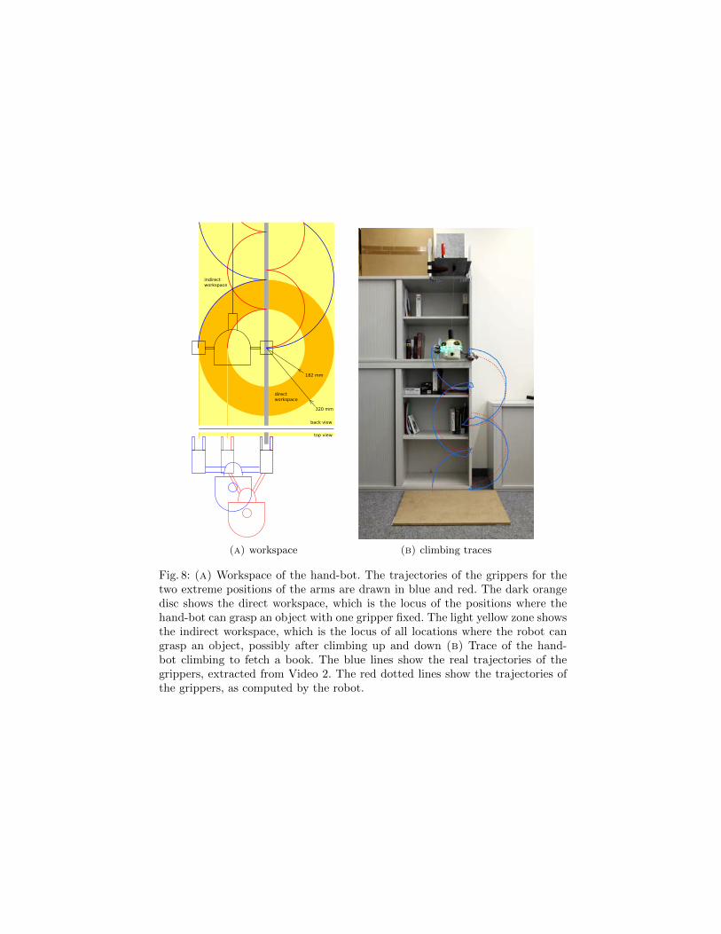
The hand-bot climbs vertical structures by rotating its arms with one gripperfixed, and by switching grippers after each half turns (Fig. 8a). At the same time,the hand-bot coils the rope which provides the main lifting force. As the hand-bot only needs one gripper attached to provide stability, it can use the otherone to manipulate objects. The hand-bot can compute the position of a gripperknowing the length of the coiled rope, the position of the head, and the extensionof the arms (Fig. 7). While keeping a gripper attached, the hand-bot can reachobjects located in a vertical disk (inner radius 18.2 cm, outer radius 32.0 cm)centered around this gripper. To access objects out of this disk, it must climb upor down, change the extensions of its arms, and then climb back to a positionwhere it can access the object. In this way, the hand-bot can reach any objectslocated at maximum at 32.0 centimeters away from climbing pole (Fig. 8a).
indirect
workspace
direct
workspace
back view
320 mm
182 mm
top view
(a) workspace (b) climbing traces
Fig. 8: (a) Workspace of the hand-bot. The trajectories of the grippers for thetwo extreme positions of the arms are drawn in blue and red. The dark orangedisc shows the direct workspace, which is the locus of the positions where thehand-bot can grasp an object with one gripper fixed. The light yellow zone showsthe indirect workspace, which is the locus of all locations where the robot cangrasp an object, possibly after climbing up and down (b) Trace of the hand-bot climbing to fetch a book. The blue lines show the real trajectories of thegrippers, extracted from Video 2. The red dotted lines show the trajectories ofthe grippers, as computed by the robot.
4 Experiment: Climb of a shelf and retrieval of a book
In this experiment, the hand-bot starts lying on the ground with its right grip-per attached to a vertical pole, in this case the border of a shelf. The hand-botfirst launches the magnet, and then climbs the shelf by switching grippers alter-natively, always keeping at least one gripper attached. To do so, the hand-botrotates its head slowly and coils the rope accordingly using its elevation motor.The hand-bot actively maintains the grippers in parallel with its body, so thatit can grasp the border of the shelf or a book. The hand-bot uses the infraredproximity sensors of the gripper and the orientation of the head to decide whento grasp. When the hand-bot reaches a specific altitude (120 cm), it scans forthe book using the proximity sensors of the gripper. When it has grasped thebook, it goes down, freely hanging at the rope. Video 11 shows this sequence.This experiment lasts for two minutes.
Fig. 8b shows the trajectories of the grippers while the hand-bot climbsthe shelf and retrieves the book. The figure shows both the real trajectoriesextracted from Video 22 and the trajectories estimated by the robot. The robotcomputes them using the length of coiled rope, the head orientation, and thearms extensions. Overall, the two trajectories match well. Both the real traceand the estimated one show a vertical displacement when the robot attaches (ordetaches) one of its gripper. The reason is that the arm is a parallel structure,so when the robot retracts (or extends) an arm, the projected position of thegripper on the vertical plane moves away from (or moves closer to) the robot.
There are several causes to the differences between the two traces. First,climbing creates high torques on the grippers’ joints, which affects the robot’sbalance that is not perfectly horizontal anymore. In the future, we will solvethis problem by fusing in the control the information from an accelerometer.Second, as the robot climbs it displaces itself on the horizontal axis, which cre-ates discrepancies with respect to the assumptions of our cinematic model whichconsiders a vertical rope. However, the passive compliance of the grippers allowsthe robot to overcome this difference and to climb successfully anyway. In thefuture, we plan to take this effect into account in our model. Third, we manuallymarked the centers of the grippers every 0.5 seconds on the video of the experi-ment, which introduced errors on the positions. In addition, the projection of thethree-dimensional scene on the two dimensional sensor of the camera introducesmajor distortions on the depth axis, and minor distortions on the other axis.
5 Future work
The current prototype of the hand-bot is able to autonomously climb a shelfand retrieve a book, provided that the robot knows the approximate position of
1 hand-bot retrieves a book, video 1: http://www.youtube.com/watch?v=92bLgE6DO2g2 hand-bot retrieves a book, video 2: http://www.youtube.com/watch?v=FFyqfO51sik
In the video, we move slightly the magnet once it is attached, because the shot ofthe current prototype is not precise enough. This does not affect the autonomy ofclimbing.
the book. In the future, we will extend the autonomy of the hand-bot in variousdirections. First, we will add the main processor board running Linux and thethree-megapixel camera to enable the robot to perceive and interact with objectsin a more dynamic way. Second, we will explore self-assembling of the hand-botwith ground robots, to provide ground mobility to the hand-bot. This will allowus to implement more complex scenarios and explore deeper scientific questionsthan what is currently possible with a single hand-bot. Third, we will analyzecollaborative tasks involving several hand-bots that manipulate large objectstogether. Finally, we will perform benchmarks of the collective approach withrespect to single-robot solutions, such as humanoids.
6 Conclusion
Albeit the use of collective robotics for service applications imposes larger de-velopment and introduction costs then an approach based on single robots, itprovides specific advantages. These include robustness, flexibility, and scalabil-ity that might prove critical for applications such as large deployments of robotsin domestic or industrial environments. However, the relationship between theadded value in performances and the additional costs in design and developmentis still unexplored, especially for complex tasks such as the ones involving ma-nipulation. Robots such as the hand-bot provide an engineering foundation toexplore this scientific question. The prototype of the hand-bot managed to suc-cessfully climb a shelf and retrieve a book autonomously. It achieved this thanksto its innovate synergy between its climbing and manipulation subsystems.
7 Acknowledgements
We thank Basilio Noris who shot all the photos of the exterior of the hand-botand provided us with material and expertise for filming. This work was sup-ported by the Swarmanoid project, which is funded by the Future and EmergingTechnologies program (IST-FET) of the European Community under grant IST-022888. The information provided is the sole responsibility of the authors anddoes not reflect the Community’s opinion. The Community is not responsiblefor any use that might be made of data appearing in this publication.
References
1. IFR Statistical Department: World Robotics 2008. IFR Statistical Department(2008)
2. Konolige, K., Fox, D., Ortiz, C., Agno, A., Eriksen, M., Limketkai, B., Ko, J.,Morisset, B., Schulz, D., Stewart, B., et al.: Centibots: Very large scale distributedrobotic teams. In: Experimental Robotics: The 9th International Symposium,Springer Tracts in Advanced Robotics (STAR), Springer (2005) 131–140
3. Sahin, E.: Swarm robotics: From sources of inspiration to domains of application.In: Swarm Robotics Workshop: State-of-the-art Survey, Springer (2005) 10–20
4. Winfield, A.F., Harper1, C.J., Nembrini, J.: Towards dependable swarms and anew discipline of swarm engineering. Swarm Robotics 3342 (2005) 126–142
5. Dorigo, M., Gambardella, L., Mondada, F., Floreano, D., Nolfi, S.: Swarmanoid:Towards humanoid robotic swarms. http://www.swarmanoid.org/
6. Groß, R., Tuci, E., Dorigo, M., Bonani, M., Mondada, F.: Object transport bymodular robots that self-assemble. In: Proceedings of the 2006 IEEE InternationalConference on Robotics and Automation. (2006) 2558–2564
7. Staritz, P., Skaff, S., Urmson, C., Whittaker, W.: Skyworker: a robot for assem-bly, inspection and maintenance of large scale orbital facilities. In: Robotics andAutomation, 2001. Proceedings 2001 ICRA. IEEE International Conference on.Volume 4., IEEE Press (2001) 4180–4185
8. Balaguer, C., Gimenez, A., Huete, A., Sabatini, A., Topping, M., Bolmsjo, G.:The MATS robot: service climbing robot for personal assistance. IEEE Robotics& Automation Magazine 13(1) (2006) 51–58
9. Hillenbrand, C., Berns, K.: Inspection of surfaces with a manipulator mounted ona climbing robot. In: 37th International Symposium on Robotics (ISR). (2006)
10. Longo, D., Muscato, G.: The alicia3 climbing robot: a three-module robot for au-tomatic wall inspection. Robotics and Automation Magazine, IEEE 13(1) (March2006) 42–50
11. Luk, B.L., Cooke, D.S., Galt, S., Collie, A.A., Chen, S.: Intelligent legged climb-ing service robot for remote maintenance applications in hazardous environments.Robotics and Autonomous Systems 53(2) (2005) 142–152
12. Zhang, H., Zhang, J., Zong, G., Wang, W., Liu, R.: Sky cleaner 3: a real pneumaticclimbing robot for glass-wall cleaning. Robotics and Automation Magazine, IEEE13(1) (March 2006) 32–41
13. Aracil, R., Saltaren, R., Reinoso, O.: A climbing parallel robot: a robot to climbalong tubular and metallic structures. Robotics and Automation Magazine, IEEE13(1) (2006) 16–22
14. Vona, M., Detweiler, C., Rus, D.: Shady: Robust Truss Climbing with MechanicalCompliances. In: International Symposium on Experimental Robotics, Springer(2006) 431–440
15. Scheidegger, N., Mondada, F., Bonani, M., Siegwart, R.: Bi-pedal Robot for RescueOperations. In: 9th International Conference on Climbing and Walking Robots.(2006) 425–430
16. Krishna, M., Bares, J., Mutschler, E.: Tethering system design for Dante II. In:1997 IEEE International Conference on Robotics and Automation, 1997. Proceed-ings. Volume 2. (1997)
17. ISO Standard 11898: Road Vehicles Interchange of Digital Information - ControllerArea Network - ISO 11898. International Organization for Standardization (1993)
18. Magnenat, S., Retornaz, P., Bonani, M., Longchamp, V., Mondada, F.: Aseba: amodular architecture for event-based control of complex robots (2009) submittedfor publication.
19. Magnenat, S., Mondada, F.: Aseba Meets D-Bus: From the Depths of a Low-LevelEvent-Based Architecture. In: IEEE TC-Soft Workshop on Event-based Systemsin Robotics (EBS-RO). (2009)