Embed Size (px)
Citation preview

This booklet has been produced topromote and encourage the correct use oflead sheet flashings, weatherings andgutter linings in building.
Nobody knows more about lead than Calder!
THEGUIDE TOGOODLEADWORK
49853 Calder GTGLW_Calder GTGLW 5425 Doc013 11/02/2010 16:20 Page 1

2
Leadsheet hasbeen inuse as abuildingmaterialforcenturies.
Lead sheet adorns theroofs of churches, offices,factories, public buildingsand homesthroughoutthe UnitedKingdombecauseof itsdurabilityand easeof use.
49853 Calder GTGLW_Calder GTGLW 5425 Doc013 11/02/2010 16:20 Page 2

3
49853 Calder GTGLW_Calder GTGLW 5425 Doc013 11/02/2010 16:20 Page 3

Thickness &weight chart 5
Borra FixingClip® 6
Lead SheetSealant 7
Patination Oil 8
Geotec Underlay,Wood Core Rolland Clips 9
Clips 10/11
Coverflashings 12/13
Abutmentflashings 14/15
Roll endsand drips 16
Ridgesand hips 17
Chimneyflashings 18
Pitchedvalley gutters 19
Box andtapered gutters 20
Secret gutters 21
Flat roofcoverings 22
Windowflashings 23
CONTENTS
IMPORTANT
4
This booklet is a guide to the correctdetailing and fixing of lead sheetflashings, weatherings and gutterlinings.
The following information conformswith the British Standard for leadworkand the recommendations of the LeadSheet Association. For more detailedtechnical information, referenceshould be made to the LSA’spublication entitled ‘The CompleteManual’ which covers the manyapplications of lead sheet in building.
Lead sheet is a proven, long-lifebuilding material. It is extremelymalleable and can be readily dressedto fit the multi-curved contours ofmany modern building materials,particularly roofing tiles. To ensurethis longevity, however, it isessential to follow a few basic rules:
•Individual pieces of lead sheetmust not exceed therecommendations set out on page5. In particular, each piece offlashing must be no longer than1.5m.
•Fixings should hold the leadsecurely in position withoutrestricting thermal movement.With flashings, regular expansionjoints (laps) will overcome therestriction caused by lead wedgingalong one side.
•Nails and screws should have asimilar life expectancy to that ofthe lead, therefore use copper,brass or stainless steel, nevergalvanised or aluminium fixings.
•Joints must allow for thermalmovement but also remainweathertight for the position wherethey are used. For example, do notuse laps or welts to join pieces ofgutter lining. The correct joint is adrip, as illustrated on page 16.
Remember, lead sheet is a fine, long-life material . . .
. . . but only when used correctly.
49853 Calder GTGLW_Calder GTGLW 5425 Doc013 11/02/2010 16:20 Page 4
LEAD SHEET BS EN12588Thicknesses to BS EN12588 tolerances of ±5%
Kg persquare metre:Thicknessin mm:
CodeNo.3
CodeNo.4
CodeNo.5
CodeNo.6
CodeNo.7
CodeNo.8
14.971.32
20.411.80
25.402.24
30.052.65
35.723.15
40.263.55
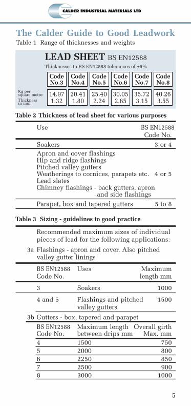
The Calder Guide to Good LeadworkTable 1 Range of thicknesses and weights
Table 2 Thickness of lead sheet for various purposes
Use BS EN12588Code No.
Soakers 3 or 4Apron and cover flashingsHip and ridge flashingsPitched valley guttersWeatherings to cornices, parapets etc. 4 or 5Lead slatesChimney flashings - back gutters, apron
and side flashings
Parapet, box and tapered gutters 5 to 8
Table 3 Sizing - guidelines to good practice
Recommended maximum sizes of individual pieces of lead for the following applications:
3a Flashings - apron and cover. Also pitched valley gutter linings
BS EN12588 Uses MaximumCode No. length mm
3 Soakers 1000
4 and 5 Flashings and pitched 1500valley gutters
3b Gutters - box, tapered and parapetBS EN12588 Maximum length Overall girthCode No. between drips mm Max. mm4 1500 7505 2000 8006 2250 8507 2500 9008 3000 1000
5
49853 Calder GTGLW_Calder GTGLW 5425 Doc013 11/02/2010 16:20 Page 5

6
FIXING CLIPthe answer to fastening lead flashing
Using the clip will securely fasten the lead flashing in place inaccordance to BS6915. The standard recommends that fixings arefixed at 450mm maximum centres.
� Lead Flashing ClipsSuitable for chase joints 6mm – 18mm
� Borra Fixing Clip®Suitable for larger chase joints 18mm+
For busy lead installers, time is money. These easy touse fixing clips will result in time saved.
49853 Calder GTGLW_Calder GTGLW 5425 Doc013 11/02/2010 16:20 Page 6

7
Why is it that so many water penetration problemsoccur at abutments? The answer often is that mortar isnot a satisfactory long-term pointing where leadflashings turn into joints in brickwork or masonry.
LEAD SHEET SEALANTthe answer to pointing problems!
The mortar is unable to adhere to both the brick and the lead whensubject to changes in temperature. It soon cracks, particularly insunny exposures, allowing water to penetrate, causing dampnessbelow. In many cases the problem is made worse by poor cleaningout of the joint which results in a wedge-shaped pointing whichquickly cracks away from the brickwork.Now there is a practical, long-term alternative to mortar pointing -Lead Sheet Sealant. This one-part, neutral-cure, high-performancesilicone-based sealant has been specially formulated for use withlead sheet flashings and its elastic properties make it ideally suitedfor pointing between lead and brickwork or masonry.
Lead Sheet Sealant - The Experts Choice!
The sealant specifically designed for pointing joints betweenlead and brickwork or masonry.
Provides a long term, flexible joint, which can absorbtemperature changes.
Avoids the problems of pointing with wet mortar,particularly in hot or frosty conditions.
Quicker, cleaner and easier to use than mortar.
The Lead Sheet Association recommends sealant.
49853 Calder GTGLW_Calder GTGLW 5425 Doc013 11/02/2010 16:20 Page 7

8
Lead sheet continues to be popular as an architecturalfeature on buildings because of its ease of use, durabilityand the pleasing grey colour of its protective patina.
PATINATION OILprotective coating for new lead
NEW FORMULATION
Patination oilspecificallydeveloped for theindustry by Calder onbehalf of the LeadSheet Association,minimises unsightlystaining and impartsa pleasing appearanceto newly applied leadsheet and flashings.Occasionally thepatina formed on leadlooks patchy and
unattractive. In rainy or damp conditions new lead will quicklydevelop an uneven powdery white, non-adherent coating of leadcarbonate, a corrosion product, which is aestheticallyunacceptable. The staining of tiles and brickwork spoils the overallappearance of the building.Patination oil will minimise this uncontrolled formation ofcarbonate, improve the hygiene on the job AND impart a pleasingappearance to the lead both ‘before’ and ‘after’ the formation of itsfinal patina.
IMPORTANTShake the oil vigorously before use.
Apply the oil evenly with a soft absorbent cloth. Workhorizontally from top to bottom maintaining a wet lower edge.Do not use a circular scrubbing motion.
Apply the oil to all newly installed lead items - large or small.
Apply the oil before any rain and at the end of the day’s work.
One coat is all that is needed.
Lift flashings and coat the underside of the lead for about50mm from the edge.
Coat the lead before turning up clips around the edges.
Remember to coat between laps.
NB: Because of the solvents it containsit is important to keep patination oilaway from roof areas where bituminousfelt has been laid, any spillage willdissolve the bitumen.
A comprehensive LSA data sheet isavailable on request.
Roof tiles spoiled by run-off staining.
49853 Calder GTGLW_Calder GTGLW 5425 Doc013 11/02/2010 16:20 Page 8

9
GEOTECUNDERLAYprevents weardue to thermalmovementGeotec 220PYunderlay is used toisolate sheet metalroofing fromsubstrates allowingmetal sheet toexpand andcontract withtemperaturechanges.
Geotec 220PY is anon-woven, needlepunched, polyestertextile underlay,weighing 220g/m2,conforming to theLead SheetAssociation’srequirements.
WOOD CORE ROLL as used on ridges, hips and flat roofingWood core roll is to be used to allow for the expansion andcontraction in lead sheet and flashing.
Wood core roll is used for joining bays of lead roofing, also onsteeply pitched roofs and lead cladding where a bold jointappearance is preferred. It is shaped to prevent wind lift.
CLIPS to hold lead permanently in positionCut to the required length fixing clips are recommended in rolls,welts, standing seams and for the clipping of lap joints andflashings.
Available in copper, tinned copper and terne coated stainless steel.
GEOTEC UNDERLAY,WOOD CORE ROLL & CLIPS
�
� �
�
� GEOTEC UNDERLAY� WOOD CORE ROLL� CLIPS
� ��
49853 Calder GTGLW_Calder GTGLW 5425 Doc013 11/02/2010 16:20 Page 9

Lead clips are only suitable for sheltered exposures. For most situationstinned copper or stainless steel should be used.
Use a minimum of 0.6mm copper or 0.4mm stainless steel for clips.
Use thicker material for exposed positions.
But why do so many clips fail in high wind conditions?
Mainly because the fixing position is not suited to the exposure.
Although the spacing of clips is important and the material usedshould relate to the exposure it is likely to receive, the mainconsideration must always be the position of the fixing points.
Clips
10 All dimensions are in mm, except where otherwise stated.
Top fixing to batten.
Additionalfixing tobattenthrough jointin top tile.Lower tiledrilled.
• The diagrams on
the right, illustrate
the simple
principle: The lower
the fixing, the
stronger the clip.
Exposed situations
500 max. centres
Max. length (each piece) 1500
150 min.
100 min.
Fixing at top.For sheltered exposures.
Additional fixing.Essential for bothmoderate and severeexposures.
Screws are preferable to nailswhen fixing clips to battens.
50
Apply patination treatment to lead
before turning clips. See page 8.
Clips and Clipping
The Calder Guide to good Leadwork
49853 Calder GTGLW_Calder GTGLW 5425 Doc013 11/02/2010 16:20 Page 10

A few basic rules . . .Space clips at 300mm to 500mm intervals to suit the exposure.
Don’t fix clips with galvanised steel nails. Use copper or stainlesssteel.
Lead clips should only be used in sheltered situations.
If in any doubt about exposure, use additional fixings.
Where extra fixings cannot be used, e.g. flashings over glazing, usea thicker gauge clip material.
(When using lead dome fixings, ensure there is no restriction ofthermal movement.)
11All dimensions are in mm, except where otherwise stated.
Coppershaped to fitsidelap of tile.
Clip formoderate andsevere exposures.
Must be tinned copper.
Clip forraking abutments.For all exposures.
Clip forshelteredexposures only.
Fixings at 450mmcentres approx.
Fixings ateach step.
75 min.
25 min.150 min.
LapLap+10
50
50
85
65
Clips to single lap tile roofs
50
150 min.
49853 Calder GTGLW_Calder GTGLW 5425 Doc013 11/02/2010 16:20 Page 11

Cover flashings are used where a felt or similar roof covering turns upagainst a wall. Code 4 lead sheet is normally used for this work and itis important that the length of each piece of flashing does not exceed1.5m. Laps between pieces should not be less than 100mm.
Use a straight piece of batten to mark a line 25mm from the top edge ofeach flashing piece and then bend the lead with the use of the dresserto form a 25mm turn into the brickwork. Each piece of flashing issecured into a joint in the brickwork as per BS6915 at 450mmmaximum centres, see page 6.
Mortar is not a satisfactory long term pointing. The mortar is unable toadhere to both the brick and the lead - when subject to changes oftemperature it cracks allowing water to penetrate. The Lead SheetAssociation recommends the use of a silicon sealant for pointing.
Copper or stainless steel clips are positioned along the lower edge ofthe flashing to suit the exposure of the building, see pages 10 and 11.
At internal and external corners the turn-in is cut and the flashingfolded. Note that the lap joint is adjacent to the corner and NOT in thecorner. The turn-in on the external corner is simply folded as shownwhereas it is necessary to insert a small piece of lead in the internalcorner to ensure a weathertight joint. This can be achieved by eitherlead welding or soldering.
Cover Flashings
12 All dimensions are in mm, except where otherwise stated.
75 min.
100 min.
25 min.
25 min.
Apply patination treatment. See page 8.
1500 max.
Lap 100 min.
Cover flashings
Point all flashingswith Lead SheetSealant.See page 7.
25 min.
75 min.
Internal Corner
External Corner
49853 Calder GTGLW_Calder GTGLW 5425 Doc013 11/02/2010 16:20 Page 12
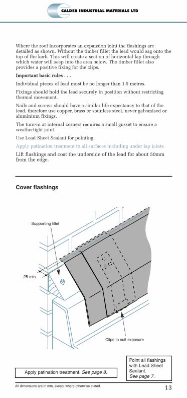
Where the roof incorporates an expansion joint the flashings aredetailed as shown. Without the timber fillet the lead would sag onto thetop of the kerb. This will create a section of horizontal lap throughwhich water will seep into the area below. The timber fillet alsoprovides a positive fixing for the clips.
Important basic rules . . .
Individual pieces of lead must be no longer than 1.5 metres.
Fixings should hold the lead securely in position without restrictingthermal movement.
Nails and screws should have a similar life expectancy to that of thelead, therefore use copper, brass or stainless steel, never galvanised oraluminium fixings.
The turn-in at internal corners requires a small gusset to ensure aweathertight joint.
Use Lead Sheet Sealant for pointing.
Apply patination treatment to all surfaces including under lap joints.
Lift flashings and coat the underside of the lead for about 50mmfrom the edge.
13All dimensions are in mm, except where otherwise stated.
Clips to suit exposure
Supporting fillet
Cover flashings
Point all flashingswith Lead SheetSealant.See page 7.
25 min.
Apply patination treatment. See page 8.
49853 Calder GTGLW_Calder GTGLW 5425 Doc013 11/02/2010 16:20 Page 13

Horizontal and raking abutment flashings should extend out over thetiles - or slates - for not less than 150mm.
Where plain (uncontoured) concrete tiles are used at low pitches, acover of 200mm is preferable, particularly in exposed positions.Alternatively, a secret gutter can be used. See page 21.
Space fixings at about 450mm centres for cover flashings and at eachstep for raking abutment flashings.
Abutment flashings
14 All dimensions are in mm, except where otherwise stated.
Abutment flashings Point all flashingswith Lead SheetSealant.See page 7.
Remember to . . .
Turn all lead flashings at least 25mm into mortarjoints.
Clip free edges of flashings to suit exposure (seepages 10 & 11)
Turn flashings at least25mm into mortar joints
Clips not shown. Thesemust be spaced to suitexposure.See pages 10 & 11
Fixings at eachstep
Form cornercorrectly
25
100 min
150-200
175
85
65
Apply patination treatment. See page 8.
49853 Calder GTGLW_Calder GTGLW 5425 Doc013 11/02/2010 16:20 Page 14

Soakers and step flashings are used to weather a raking abutment wherethe roof is covered with slates or plain tiles. While Code 3 is suitablefor soakers, Code 4 is the minimum thickness to use for all flashings.
The setting-out and cutting of the steps (see below) is the same for bothflashings with soakers and for combined step-and-cover flashings oversingle-lap tiling.
An alternative method for more exposed situations is a single-stepflashing which can be used over soakers, cover flashings or secretgutters.
15All dimensions are in mm, except where otherwise stated.
Abutment flashings with soakers
Single steps withcover flashing
Single steps withsecret gutter
Fixings at
each step
Soakers
Flashing set
out and cut
FoldCut to waste
1500
max
.
WaterlineNo cuts are madebelow this line
100
75
Soaker
Point all flashingswith Lead SheetSealant.See page 7.
Fixings at
each step
25mm
turn-in
Cover
flashing
75 min
15 max50 min
75 min
75 min
overlap
150-200
6585
49853 Calder GTGLW_Calder GTGLW 5425 Doc013 11/02/2010 16:20 Page 15

Roll ends and drips can be formed either by bossing or leadwelding.
When a wood-cored roll is used to divide a wide gutter, the undercloakshould only be nailed, using copper or stainless steel nails, to the rollfor the upper third of its length.
The end of the wood roll is usually splayed and it is important for thebase of the roll to finish at the drip edge, thereby avoiding a horizontallap in front of the roll, through which water could penetrate.
Drip undercloaks should be rebated into the decking, otherwiserainwater will ‘pond’ near the front edge of the drip.
Splash laps can be omitted if an adequate lap is maintained at roll endsand drip abutments.
Roll ends and drips
16 All dimensions are in mm, except where otherwise stated.
Roll ends and drips
BS EN12588Code No.
4
5
6
7
8
Min dripheight ‘h’
55mm
55mm
55mm
60mm
60mm
Extend undercloak 40mm min.
when splashlap on roll overcloak
is omitted
Alternative overcloak
detail for Codes 4 and 5
‘h’
5 min.
Splashlap optional
for gutter linings
50mm min. drip
height for narrow
gutters without roll
Splashlap can
be omitted for
codes 6,7, and 8
Fixings, using copper or
stainless steel nails, to the
undercloak - upper third
of roll length only
3 - 5
Apply patination treatment. See page 8.
49853 Calder GTGLW_Calder GTGLW 5425 Doc013 11/02/2010 16:20 Page 16

Ridges and hips
17All dimensions are in mm, except where otherwise stated.
A
A
B
C
B
C
150 min.
Lap to suit
roof pitch
Roll fixed
5mm min.
above slate
150 min
150 min.
150 min.
Ridges and hips
Fixings at
top of each
hip flashing
Lead ridges and hips are normally used on slated roofs. A wood roll isrequired and should be fixed as shown in the diagram below. Theflashings must extend over the slates or tiles a minimum of 150mm oneach side.
A practical method of fitting the flashings that will avoid thinning atthe corners is to form the lead into a trough. The lead is pressed downover the roll to fit closely to both the roll and the roof surfaces. Use aminimum of Code 4 lead sheet for both ridge and hip flashings andagain, the maximum length of each piece should not exceed 1.5m.
Laps between pieces should not be less than 150mm - although forpitches below 30° the hip laps should be increased to 200mm.
It is important to fix the top of each piece of hip flashing to the woodroll with copper or stainless steel clout nails. Nails are not required atthe ridge laps.
Clip fixings along the sides of the flashings are absolutely essential andshould be spaced to suit the exposure of the building - see pages 10 and11. Note the extra fixings in the clips shown on both the ridge and hiplaps. In all but very sheltered exposures these fixings will be required.
At the junction between ridge and hip flashings and also where the rollterminates at the hip end, the lead will need to be dressed to fit oralternatively can be formed by leadwelding or soldering.
Apply patination treatment. See page 8.
49853 Calder GTGLW_Calder GTGLW 5425 Doc013 11/02/2010 16:20 Page 17
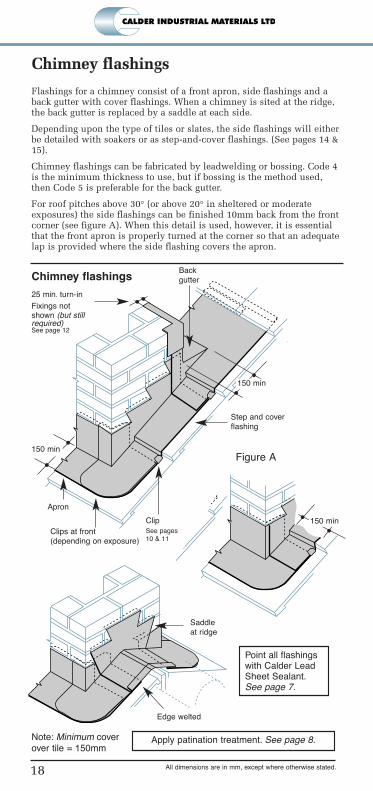
Flashings for a chimney consist of a front apron, side flashings and aback gutter with cover flashings. When a chimney is sited at the ridge,the back gutter is replaced by a saddle at each side.
Depending upon the type of tiles or slates, the side flashings will eitherbe detailed with soakers or as step-and-cover flashings. (See pages 14 &15).
Chimney flashings can be fabricated by leadwelding or bossing. Code 4is the minimum thickness to use, but if bossing is the method used,then Code 5 is preferable for the back gutter.
For roof pitches above 30° (or above 20° in sheltered or moderateexposures) the side flashings can be finished 10mm back from the frontcorner (see figure A). When this detail is used, however, it is essentialthat the front apron is properly turned at the corner so that an adequatelap is provided where the side flashing covers the apron.
Chimney flashings
18 All dimensions are in mm, except where otherwise stated.
Chimney flashings
Point all flashingswith Calder LeadSheet Sealant.See page 7.
25 min. turn-in
Fixings notshown (but stillrequired)See page 12
Back
gutter
Step and cover
flashing
Saddle
at ridge
Edge welted
Apron
Clips at front
(depending on exposure)
Note: Minimum cover
over tile = 150mm
Figure A
Clip
See pages
10 & 11
150 min
150 min
150 min
Apply patination treatment. See page 8.
49853 Calder GTGLW_Calder GTGLW 5425 Doc013 11/02/2010 16:20 Page 18

To provide a weathering life equal to that of the tiles or slates whichoverhang on each side, lead sheet pitched valley gutter linings shouldbe fixed in lengths not exceeding 1.5m. Each piece should be fixedacross the top with two rows of copper or stainless steel clout nails.
Valley boards should be level with the tops of the rafters so that tilingbattens and tilting fillets are the same height. With traditional roofingthe valley boards can be recessed into the rafters; but when roof trussesare used the boards must be cut to fit between the rafters. For pitches of30° and above the lap between pieces should be 150mm, increasing to220mm for a pitch of 20°.
Some important points . . .
Don’t nail down the sides as this will restrict free thermal movementand result in failure.
Don’t lay sarking felt under the lead. It will cause the lead to stick tothe boards in hot weather.
Use copper or stainless steel nails to fix the lead - not galvanized steelor aluminium.
Pitched valley gutters
19All dimensions are in mm, except where otherwise stated.
Saddle piece
Separators
Tilting fillet
125 min
2 rows of fixings
at head of
underlap (first row
25mm from top of
gutter)
No fixings down
sides
150 min
150 min.
Pitched valley gutters
Apply patination treatment. See page 8.
49853 Calder GTGLW_Calder GTGLW 5425 Doc013 11/02/2010 16:20 Page 19
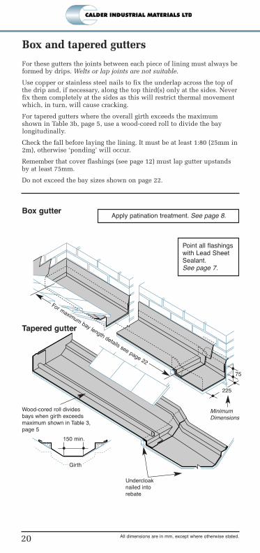
For these gutters the joints between each piece of lining must always beformed by drips. Welts or lap joints are not suitable.
Use copper or stainless steel nails to fix the underlap across the top ofthe drip and, if necessary, along the top third(s) only at the sides. Neverfix them completely at the sides as this will restrict thermal movementwhich, in turn, will cause cracking.
For tapered gutters where the overall girth exceeds the maximumshown in Table 3b, page 5, use a wood-cored roll to divide the baylongitudinally.
Check the fall before laying the lining. It must be at least 1:80 (25mm in2m), otherwise ‘ponding’ will occur.
Remember that cover flashings (see page 12) must lap gutter upstandsby at least 75mm.
Do not exceed the bay sizes shown on page 22.
Box and tapered gutters
20 All dimensions are in mm, except where otherwise stated.
Box gutter
Point all flashingswith Lead SheetSealant.See page 7.
Wood-cored roll divides
bays when girth exceeds
maximum shown in Table 3,
page 5
Undercloak
nailed into
rebate
For maximum bay length details see page 22
225
150 min.
Girth
MinimumDimensions
Tapered gutter
75
Apply patination treatment. See page 8.
49853 Calder GTGLW_Calder GTGLW 5425 Doc013 11/02/2010 16:20 Page 20

Renewal of roof coverings on terraced housing often results in asituation where different tiles abut over a party wall. A practicalmethod of weathering these intersections is to use a secret gutter. Thesizing and fixing of the linings is similar to that for pitched valleygutters, as shown on page 19.
The methods shown below are superior alternatives to the bedded hiptiles commonly used. The use of lead sheet in these situations gives thefollowing advantages:
It allows for both structural and thermal movement between adjacentproperties without risk of water penetration.
Tiles and slates on either side of the junction can be readily repaired orrenewed without disturbance to the adjoining property.
Properly detailed and installed, the leadwork will have a durability atleast equal to that of the best tiles or slates.
Secret gutters
21All dimensions are in mm, except where otherwise stated.
Secret gutter over party wall
Copper or
stainless steel
clout nails
Board spanning party wall
75 min.
gutter width
15 max. gap
between tiles
Gutter lining max.
length 1.5m
2525
Nail details
Note spacing.
Do not create a
perforated edge.
49853 Calder GTGLW_Calder GTGLW 5425 Doc013 11/02/2010 16:20 Page 21

Lead sheet is the ideal material for weathering projections and canopiesover windows and doors.
Large lengths and areas can be divided into bays by wood-cored rolls sothat no piece of lead exceeds the recommended dimensions.
Front and side edges should be clipped to suit the exposure.
A few tips . . .
Don’t use an underlay which could cause adhesion to the substrateduring hot weather. Use a building paper or a geotextile underlay.
Don’t nail or tack the edges to prevent wind lift. Use clips.
Never oversize the bays. Divide them with wood-cored roll or,alternatively, use a thicker sheet.
Flat roof coverings
22 All dimensions are in mm, except where otherwise stated.
Apply patination treatment.
See page 8.
Flat roof coverings
Recommended maximum dimensions.
Illustrations are diagrammatic
BS EN12588
Code No.
4 500 1500
5 600 2000
6 675 2250
7 675 2500
8 750 3000
Maximum spacing of
joints with the fall (mm)
Maximum distance
between drips (mm)
a. Max bay size
b. Alternative bay size
Code 6
Code 6
840
2250
675
1800
49853 Calder GTGLW_Calder GTGLW 5425 Doc013 11/02/2010 16:20 Page 22
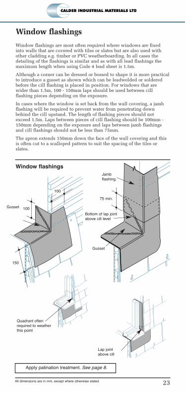
Window flashings are most often required where windows are fixedinto walls that are covered with tiles or slates but are also used withother cladding e.g. timber or PVC weatherboarding. In all cases thedetailing of the flashings is similar and as with all lead flashings themaximum length when using Code 4 lead sheet is 1.5m.
Although a corner can be dressed or bossed to shape it is more practicalto introduce a gusset as shown which can be leadwelded or solderedbefore the cill flashing is placed in position. For windows that arewider than 1.5m, 100 - 150mm laps should be used between cillflashing pieces depending on the exposure.
In cases where the window is set back from the wall covering, a jambflashing will be required to prevent water from penetrating downbehind the cill upstand. The length of flashing pieces should notexceed 1.5m. Laps between pieces of cill flashing should be 100mm -150mm depending on the exposure and laps between jamb flashingsand cill flashings should not be less than 75mm.
The apron extends 150mm down the face of the wall covering and thisis often cut to a scalloped pattern to suit the spacing of the tiles orslates.
Window flashings
23All dimensions are in mm, except where otherwise stated.
Gusset 100
150
Gusset
75 min.
Jamb
flashing.
Bottom of lap joint
above cill level
Quadrant often
required to weather
this point
Lap joint
above cill
Window flashings
100
Apply patination treatment. See page 8.
49853 Calder GTGLW_Calder GTGLW 5425 Doc013 11/02/2010 16:20 Page 23

Health and Safety Precautions
To ensure your well-being, Calder IndustrialMaterials Limited have produced Health and
Safety Data Sheets. Ask your builders merchant toobtain copies for you.
Caring for the environment
Both old lead and new lead off-cuts can berecycled. Calder Industrial Materials Limited’s
Rolled lead to BS EN12588 is manufactured using recycled lead
Copies of this booklet are available FREE fromyour merchant with purchases of
Calder Quality Lead.
0210/ DOCSG002
Produced by Calder Industrial Materials LimitedTel: 0191 482 7350
www.calderlead.co.ukE-mail: [email protected]
EMS 68146
A Calder Group Company
49853 Calder GTGLW_Calder GTGLW 5425 Doc013 11/02/2010 16:20 Page 24