Embed Size (px)
Citation preview

The Government of the Hong Kong Special Administrative Region
WORKS BUREAU
Study on CAD Standard for Works Departments
Agreement No. CE 15/2000
Consultation Document October 2001
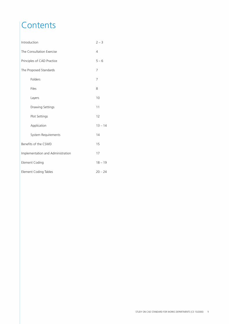
Contents
Introduction 2 – 3
The Consultation Exercise 4
Principles of CAD Practice 5 – 6
The Proposed Standards 7
Folders 7
Files 8
Layers 10
Drawing Settings 11
Plot Settings 12
Application 13 – 14
System Requirements 14
Benefits of the CSWD 15
Implementation and Administration 17
Element Coding 18 – 19
Element Coding Tables 20 – 24
STUDY ON CAD STANDARD FOR WORKS DEPARTMENTS (CE 15/2000) 1

Introduction
The Use of CAD in Hong Kong
Computer Aided Drafting (CAD) systems are used to produce virtually all drawings related to construction in Hong Kong. CAD systems are used by Government Departments, client organisations, consultants, contractors and suppliers.
Most of these organisations have developed in-house standards to ensure data compatibility and uniform presentation of their drawings. These standards are usually developed to meet in-house requirements and do not take account of others’ standards. This is an understandable approach as there are no common industry standards to follow. Some client organisations require those supplying drawings to provide them to the client’s own standards. In many cases however such requirements are not specified.
Two main CAD systems are used in Hong Kong; they are AutoCAD and Microstation. Although data can be transferred between the systems, the small differences that exist in the many CAD standards being used mean that data transfers are very often not wholly successful. As a result, the benefits that would arise from a free flow of CAD data between parties involved in the whole life-cycle of a project are not realised.
The Use of CAD within Government
Most Hong Kong Government construction projects fall under the portfolio of those departments that come under the umbrella of the Works Bureau. These departments are:
• Architectural Services Department A
• Civil Engineering Department M
• Drainage Services Department M
• Electrical & Mechanical Services Department A
• Highways Department M
• Territory Development Department M
• Water Supplies Department A
Transport Department M, although not under the Works Bureau, is also involved in many Government construction projects.
Each of these departments runs a CAD system. There is a roughly equal split between those that use AutoCAD and those that use Microstation, which is indicated above by the letters A and M after the departments’ names.
Each of the departments has developed its own CAD standards to suit its own needs. No one standard is better than another, they are just different. As a result, CAD data exchange between the departments is limited due to incompatibilities in the data.
The same incompatibilities of data and lack of a common, published set of CAD standards also prevent easy exchange of electronic drawings between the departments and their consultants, contractors and suppliers.
The Purpose of the CSWD Study
To overcome the differences in the departments’ CAD standards, the Works Bureau has commissioned the ‘CSWD Study’. CSWD stands for ‘CAD Standard for Works Departments’.
The purpose of the CSWD Study is to align the Works Departments’ CAD standards to produce a common set of standards that will be adopted by all the departments and to which their consultants, contractors and suppliers will be required to work. It is envisaged that the CSWD will become the “de-facto” CAD standard used in the Hong Kong construction industry.
STUDY ON CAD STANDARD FOR WORKS DEPARTMENTS (CE 15/2000) 2
CSWD
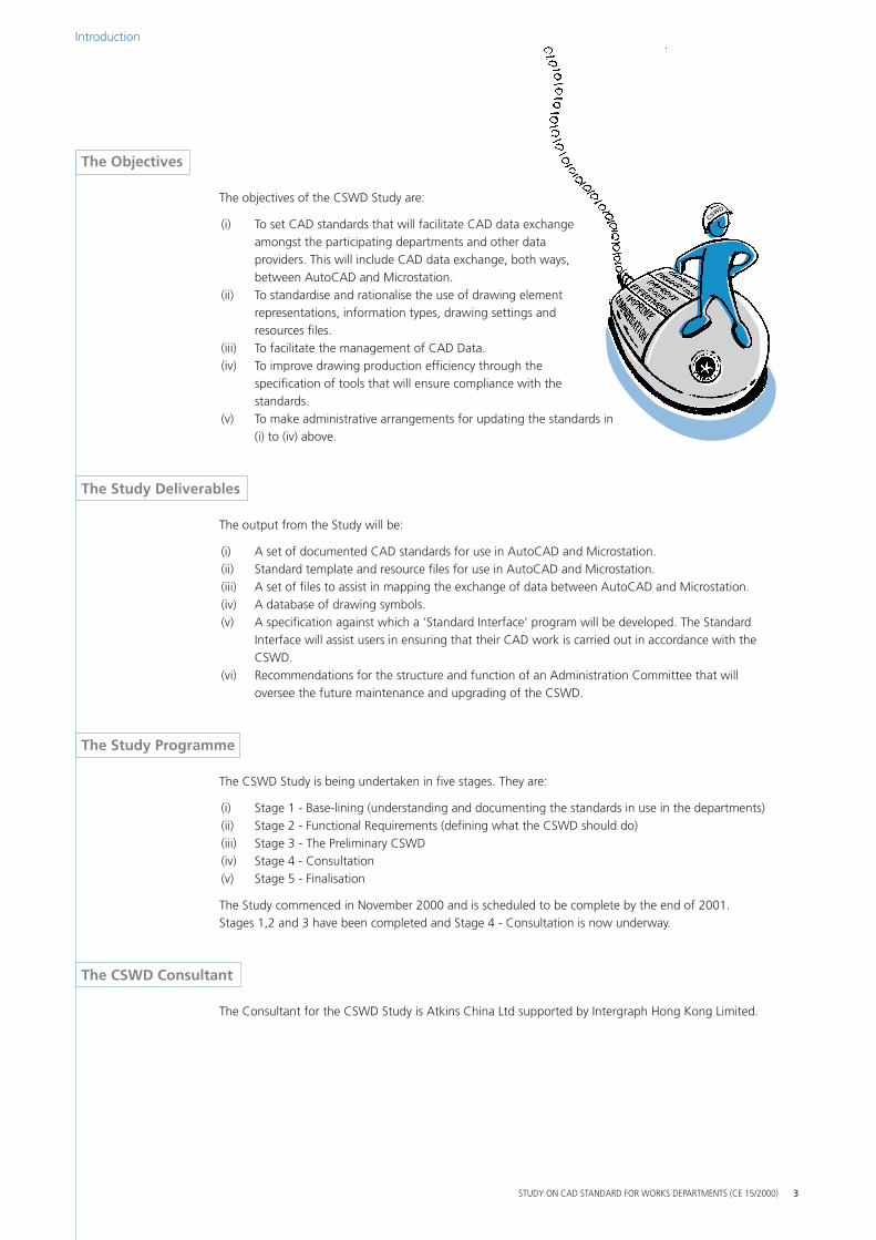
The Objectives
The objectives of the CSWD Study are:
(i) To set CAD standards that will facilitate CAD datamongst the participating departments and otheproviders. This will include CAD data exchange, between AutoCAD and Microstation.
(ii) To standardise and rationalise the use of drawingrepresentations, information types, drawing settiresources files.
(iii) To facilitate the management of CAD Data. (iv) To improve drawing production efficiency throug
specification of tools that will ensure compliancestandards.
(v) To make administrative arrangements for updati(i) to (iv) above.
a exchange r data
both ways,
element ngs and
h the with the
ng the standards in
The Study Deliverables
The output from the Study will be:
(i) A set of documented CAD standards for use in AutoCAD and Microstation. (ii) Standard template and resource files for use in AutoCAD and Microstation. (iii) A set of files to assist in mapping the exchange of data between AutoCAD and Microstation. (iv) A database of drawing symbols. (v) A specification against which a ‘Standard Interface’ program will be developed. The Standard
Interface will assist users in ensuring that their CAD work is carried out in accordance with the CSWD.
(vi) Recommendations for the structure and function of an Administration Committee that will oversee the future maintenance and upgrading of the CSWD.
The Study Programme
The CSWD Study is being undertaken in five stages. They are:
(i) Stage 1 - Base-lining (understanding and documenting the standards in use in the departments) (ii) Stage 2 - Functional Requirements (defining what the CSWD should do) (iii) Stage 3 - The Preliminary CSWD (iv) Stage 4 - Consultation (v) Stage 5 - Finalisation
The Study commenced in November 2000 and is scheduled to be complete by the end of 2001. Stages 1,2 and 3 have been completed and Stage 4 - Consultation is now underway.
The CSWD Consultant
The Consultant for the CSWD Study is Atkins China Ltd supported by Intergraph Hong Kong Limited.
STUDY ON CAD STANDARD FOR WORKS DEPARTMENTS (CE 15/2000)
Introduction
3
Why Consult?
In that Government is the major initiator of construction projects in Hong Kong, the requirements that it develops for the structure and format of drawings supplied to it will affect Hong Kong’s consultants, contractors and suppliers. Under the Study, organisations that will be affected by the CSWD have been grouped as ‘Stakeholders’. The purpose of the Consultation Stage is:
• to introduce the CSWD to the Stakeholders; • to secure support for the CSWD; and • to obtain feedback on the CSWD, in particular the requirements and concerns
of the Stakeholders.
The Consultation Document and Web Site
The purpose of this document is therefore to present the proposed CSWD to Stakeholders. The contents of this document, together with some sample drawings, can also be found on the Works Bureau’s web site at www.wb.gov.hk/gov
Presentations of the proposed standards will be made to Stakeholders. The presentations will cover and supplement the information given in this document and sample drawings will be displayed. The presentations will be held during the week beginning 30th October 2001 at the offices of:
Atkins China Ltd 15/F, Miramar Tower 132 Nathan Road Tsim Sha Tsui Kowloon
Please contact John Newby on 2972 1900 or e-mail [email protected] for more details. All are welcome.
Presentations
Trials
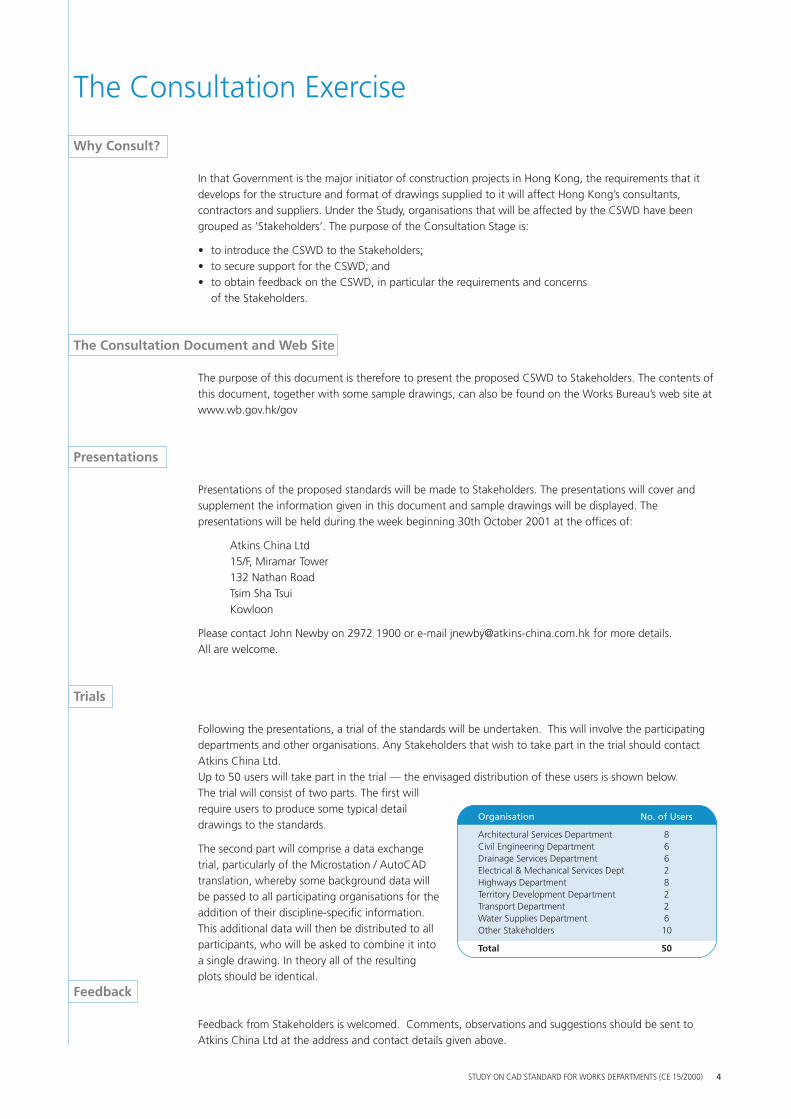
Following the presentations, a trial of the standards will be undertaken. This will involve the participating departments and other organisations. Any Stakeholders that wish to take part in the trial should contact Atkins China Ltd. Up to 50 users will take part in the trial — the envisaged distribution of these users is shown below. The trial will consist of two parts. The first will require users to produce some typical detail drawings to the standards.
The second part will comprise a data exchange trial, particularly of the Microstation / AutoCAD translation, whereby some background data will be passed to all participating organisations for the addition of their discipline-specific information. This additional data will then be distributed to all participants, who will be asked to combine it into a single drawing. In theory all of the resulting plots should be identical.
Feedback
Feedback from Stakeholders is welcomed. Comments, observations and suggestions should be sent to Atkins China Ltd at the address and contact details given above.
The Consultation Exercise
Organisation No. of Users
Architectural Services Department 8 Civil Engineering Department 6 Drainage Services Department 6 Electrical & Mechanical Services Dept 2 Highways Department 8 Territory Development Department 2 Transport Department 2 Water Supplies Department 6 Other Stakeholders 10
Total 50
STUDY ON CAD STANDARD FOR WORKS DEPARTMENTS (CE 15/2000) 4
Principles of CAD Practice
The CSWD are based on good CAD practice
This section contains a brief description of what is considered to be good CAD practice in the production of drawings, together with some definitions that arise from this, which are referred to later in the document. The CSWD have been developed to support these principles.
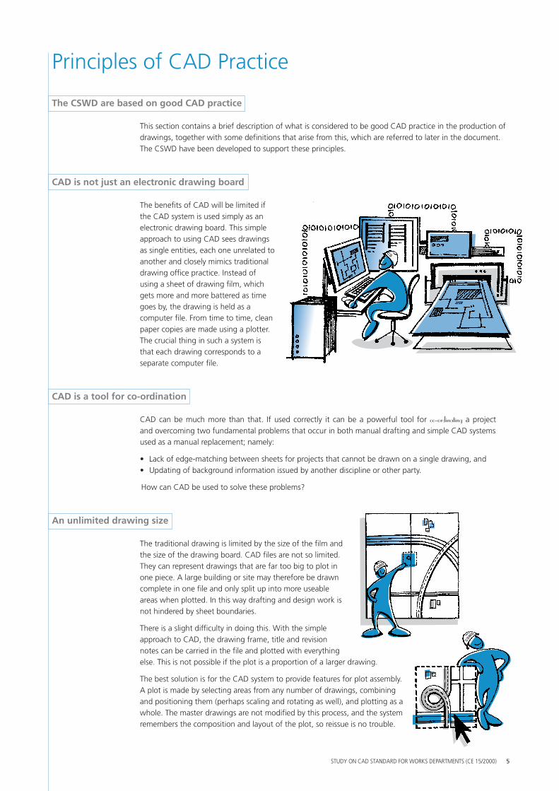
CAD is not just an electronic drawing board
The benefits of CAD will be limited if the CAD system is used simply as an electronic drawing board. This simple approach to using CAD sees drawings as single entities, each one unrelated to another and closely mimics traditional drawing office practice. Instead of using a sheet of drawing film, which gets more and more battered as time goes by, the drawing is held as a computer file. From time to time, clean paper copies are made using a plotter. The crucial thing in such a system is that each drawing corresponds to a separate computer file.
CAD is a tool for co-ordination
CAD can be much more than that. If used correcand overcoming two fundamental problems that ocused as a manual replacement; namely:
• Lack of edge-matching between sheets for proje• Updating of background information issued by a
How can CAD be used to solve these problems?
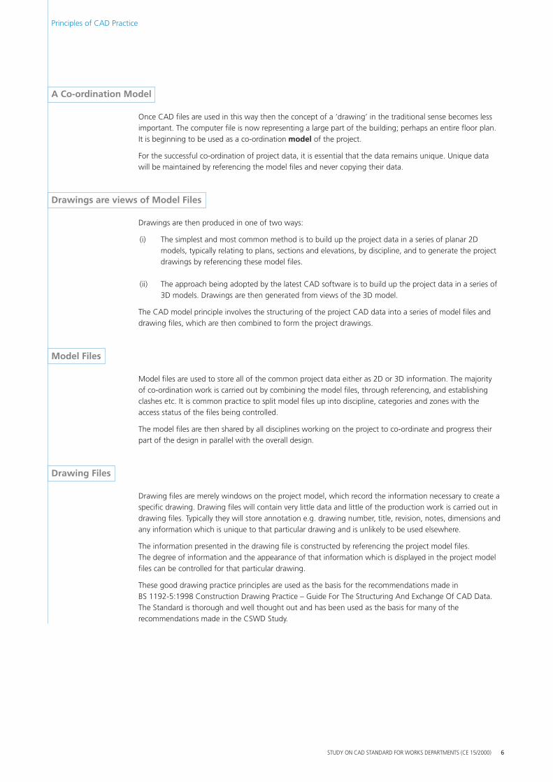
An unlimited drawing size
The traditional drawing is limited by the size of the the size of the drawing board. CAD files are not so They can represent drawings that are far too big to one piece. A large building or site may therefore becomplete in one file and only split up into more useareas when plotted. In this way drafting and designnot hindered by sheet boundaries.
There is a slight difficulty in doing this. With the siapproach to CAD, the drawing frame, title and revinotes can be carried in the file and plotted with eveelse. This is not possible if the plot is a proportion o
The best solution is for the CAD system to provide fA plot is made by selecting areas from any number
WD
tly it can be a powerful tool for co-ordinating a project cur in both manual drafting and simple CAD systems
cts that cannot be drawn on a single drawing, and nother discipline or other party.
film and limited. plot in drawn able work is
mple sion rything f a larger drawing.
eatures for plot assembly. of drawings, combining
and positioning them (perhaps scaling and rotating as well), and plotting as a whole. The master drawings are not modified by this process, and the system remembers the composition and layout of the plot, so reissue is no trouble.
STUDY ON CAD STANDARD FOR WORKS DEPARTMENTS (CE 15/2000)
CSWD
CSW
D
5
CS
Principles of CAD Practice
A Co-ordination Model
Once CAD files are used in this way then the concimportant. The computer file is now representing It is beginning to be used as a co-ordination mod
For the successful co-ordination of project data, it will be maintained by referencing the model files
Drawings are views of Model Files
Drawings are then produced in one of two ways:
(i) The simplest and most common method is
ept of a ‘drawing’ in the traditional sensea large part of the building; perhaps an eel of the project.
is essential that the data remains unique.and never copying their data.
to build up the project data in a series of models, typically relating to plans, sections and elevations, by discipline, and to genedrawings by referencing these model files.
(ii) The approach being adopted by the latest CAD software is to build up the project da3D models. Drawings are then generated from views of the 3D model.
The CAD model principle involves the structuring of the project CAD data into a series of mdrawing files, which are then combined to form the project drawings.
Model Files
Model files are used to store all of the common project data either as 2D or 3D informationof co-ordination work is carried out by combining the model files, through referencing, andclashes etc. It is common practice to split model files up into discipline, categories and zoneaccess status of the files being controlled.
The model files are then shared by all disciplines working on the project to co-ordinate and part of the design in parallel with the overall design.
Drawing Files
Drawing files are merely windows on the project model, which record the information necespecific drawing. Drawing files will contain very little data and little of the production work drawing files. Typically they will store annotation e.g. drawing number, title, revision, notes,any information which is unique to that particular drawing and is unlikely to be used elsew
The information presented in the drawing file is constructed by referencing the project modThe degree of information and the appearance of that information which is displayed in thfiles can be controlled for that particular drawing.
These good drawing practice principles are used as the basis for the recommendations madBS 1192-5:1998 Construction Drawing Practice – Guide For The Structuring And Exchange The Standard is thorough and well thought out and has been used as the basis for many ofrecommendations made in the CSWD Study.
becomes less ntire floor plan.
Unique data
planar 2D rate the project
ta in a series of
odel files and
. The majority establishing s with the
progress their
ssary to create a is carried out in dimensions and here.
el files. e project model
e in Of CAD Data. the
STUDY ON CAD STANDARD FOR WORKS DEPARTMENTS (CE 15/2000) 6
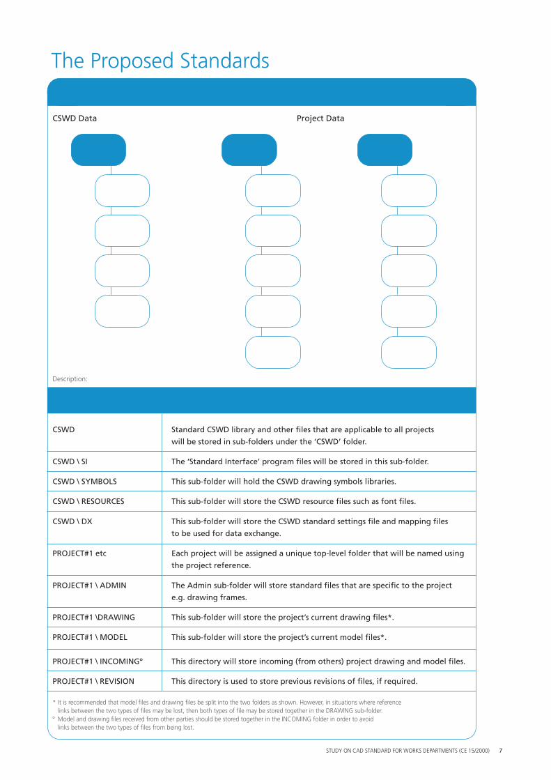
Standard Folder (Directory) Structure common to AutoCAD and Microstation
CSWD Data Project Data
CSWD PROJECT#1 PROJECT#2
SI ADMIN ADMIN FOLD
ERS
SYMBOLS DRAWING DRAWING
RESOURCES MODEL MODEL
DX INCOMING INCOMING
The Proposed Standards
REVISION REVISION
Description:
Folder Folder Contents
CSWD Standard CSWD library and other files that are applicable to all projects
will be stored in sub-folders under the ‘CSWD’ folder.
CSWD \ SI The ‘Standard Interface’ program files will be stored in this sub-folder.
CSWD \ SYMBOLS This sub-folder will hold the CSWD drawing symbols libraries.
CSWD \ RESOURCES This sub-folder will store the CSWD resource files such as font files.
CSWD \ DX This sub-folder will store the CSWD standard settings file and mapping files
to be used for data exchange.
PROJECT#1 etc Each project will be assigned a unique top-level folder that will be named using
the project reference.
PROJECT#1 \ ADMIN The Admin sub-folder will store standard files that are specific to the project
e.g. drawing frames.
PROJECT#1 \DRAWING This sub-folder will store the project’s current drawing files*.
PROJECT#1 \ MODEL This sub-folder will store the project’s current model files*.
PROJECT#1 \ INCOMINGº This directory will store incoming (from others) project drawing and model files.
PROJECT#1 \ REVISION This directory is used to store previous revisions of files, if required.
* It is recommended that model files and drawing files be split into the two folders as shown. However, in situations where reference links between the two types of files may be lost, then both types of file may be stored together in the DRAWING sub-folder.
º Model and drawing files received from other parties should be stored together in the INCOMING folder in order to avoid links between the two types of files from being lost.
STUDY ON CAD STANDARD FOR WORKS DEPARTMENTS (CE 15/2000) 7
FILE
SET
TIN
GS
FILE
NA
MIN
G
A
The Proposed Standards
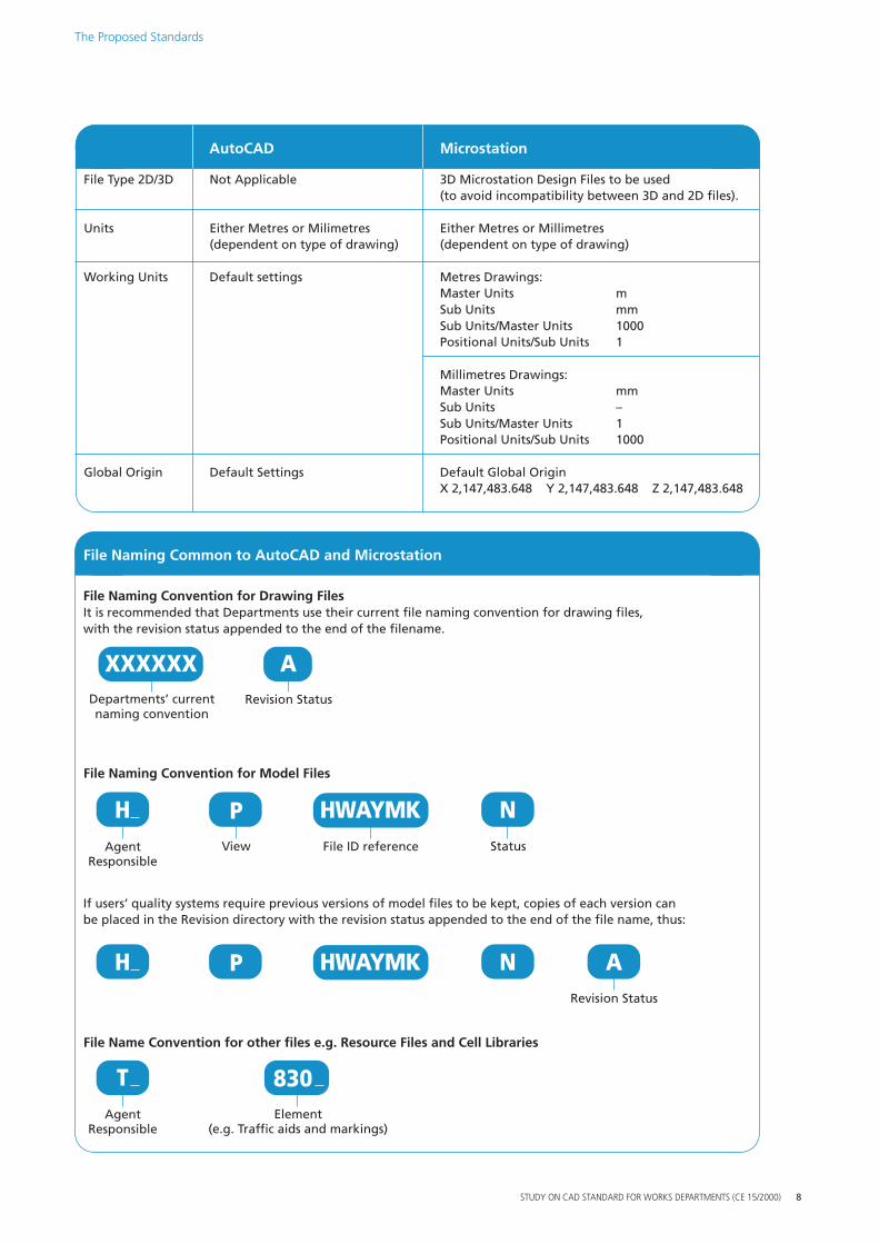
AutoCAD Microstation
File Type 2D/3D Not Applicable 3D Microstation Design Files to be used (to avoid incompatibility between 3D and 2D files).
Units Either Metres or Milimetres Either Metres or Millimetres (dependent on type of drawing) (dependent on type of drawing)
Working Units Default settings Metres Drawings: Master Units m Sub Units mm Sub Units/Master Units 1000 Positional Units/Sub Units 1
Millimetres Drawings: Master Units mm Sub Units – Sub Units/Master Units 1 Positional Units/Sub Units 1000
Global Origin Default Settings Default Global Origin X 2,147,483.648 Y 2,147,483.648 Z 2,147,483.648
File Naming Common to AutoCAD and Microstation
File Naming Convention for Drawing Files It is recommended that Departments use their current file naming convention for drawing files, with the revision status appended to the end of the filename.
Departments’ current naming convention
XXXXXX A Revision Status
File Naming Convention for Model Files
File Name Convention for other files e.g. Resource Files and Cell Libraries
Agent Responsible
T Element
(e.g. Traffic aids and markings)
If users’ quality systems require previous versions of model files to be kept, copies of each version can be placed in the Revision directory with the revision status appended to the end of the file name, thus:
830
Agent Responsible
H File ID reference
HWAYMK N Status
P View
H HWAYMK P N A Revision Status
STUDY ON CAD STANDARD FOR WORKS DEPARTMENTS (CE 15/2000) 8
FILE
NA
MIN
G
The Proposed Standards
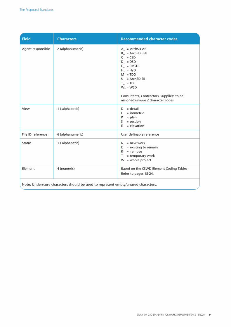
Field Characters Recommended character codes
Agent responsible 2 (alphanumeric) A_ = ArchSD AB B_ = ArchSD BSB C_ = CED D_ = DSD E_ = EMSD H_ = HyD M_ = TDD S_ = ArchSD SB T_ = TD W_ = WSD
Consultants, Contractors, Suppliers to be assigned unique 2 character codes.
View 1 ( alphabetic) D = detail I = isometric P = plan S = section E = elevation
File ID reference 6 (alphanumeric) User definable reference
Status 1 ( alphabetic) N = new work E = existing to remain R = remove T = temporary work W = whole project
Element 4 (numeric) Based on the CSWD Element Coding Tables
Refer to pages 18-24.
Note: Underscore characters should be used to represent empty/unused characters.
STUDY ON CAD STANDARD FOR WORKS DEPARTMENTS (CE 15/2000) 9
LAY
ER A
SSIG
NM
ENT
LAY
ER
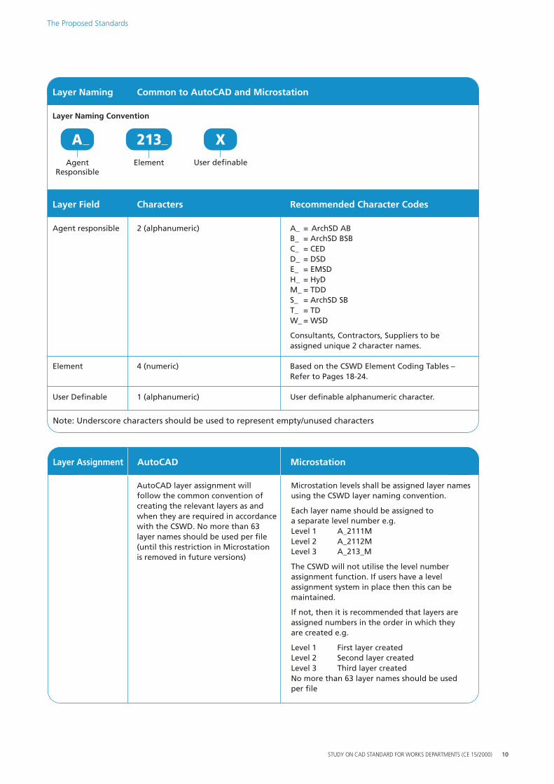
Layer Field Characters Recommended Character Codes
Agent responsible 2 (alphanumeric) A_ = ArchSD AB B_ = ArchSD BSB C_ = CED D_ = DSD E_ = EMSD H_ = HyD M_ = TDD S_ = ArchSD SB T_ = TD W_ = WSD
Consultants, Contractors, Suppliers to be assigned unique 2 character names.
Element 4 (numeric) Based on the CSWD Element Coding Tables – Refer to Pages 18-24.
User Definable 1 (alphanumeric) User definable alphanumeric character.
Note: Underscore characters should be used to represent empty/unused characters
AutoCAD layer assignment will follow the common convention of creating the relevant layers as and when they are required in accordance with the CSWD. No more than 63 layer names should be used per file (until this restriction in Microstation is removed in future versions)
Layer Assignment AutoCAD Microstation
Microstation levels shall be assigned layer names using the CSWD layer naming convention.
Each layer name should be assigned to a separate level number e.g. Level 1 A_2111M Level 2 A_2112M Level 3 A_213_M
The CSWD will not utilise the level number assignment function. If users have a level assignment system in place then this can be maintained.
If not, then it is recommended that layers are assigned numbers in the order in which they are created e.g.
Level 1 First layer created Level 2 Second layer created Level 3 Third layer created No more than 63 layer names should be used per file
STUDY ON CAD STANDARD FOR WORKS DEPARTMENTS (CE 15/2000) 10
NA
MIN
G
A
Layer Naming Common to AutoCAD and Microstation
Layer Naming Convention
Agent Responsible
A X User definable
213 Element
The Proposed Standards
DR
AW
ING
SET
TIN
GS
The Proposed Standards
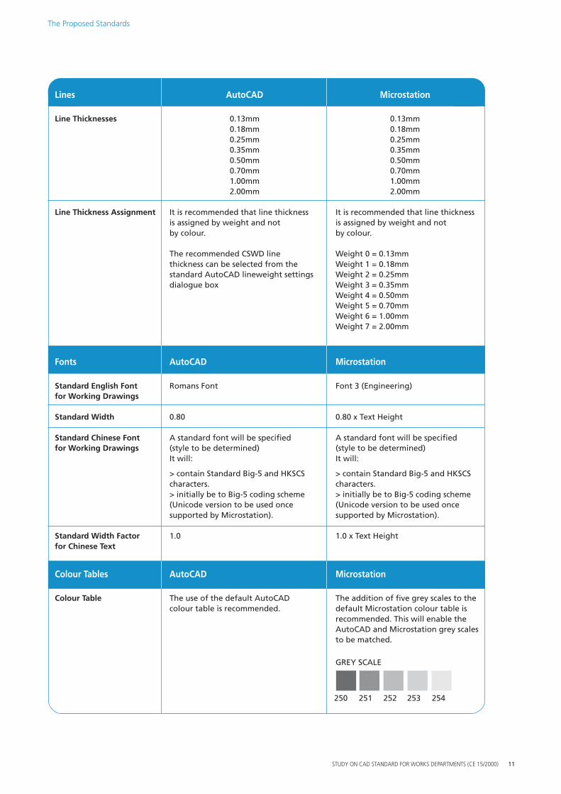
Lines AutoCAD Microstation
Line Thicknesses 0.13mm 0.13mm 0.18mm 0.18mm 0.25mm 0.25mm 0.35mm 0.35mm 0.50mm 0.50mm 0.70mm 0.70mm 1.00mm 1.00mm 2.00mm 2.00mm
Line Thickness Assignment It is recommended that line thickness It is recommended that line thickness is assigned by weight and not is assigned by weight and not by colour. by colour.
The recommended CSWD line Weight 0 = 0.13mm thickness can be selected from the Weight 1 = 0.18mm standard AutoCAD lineweight settings Weight 2 = 0.25mm dialogue box Weight 3 = 0.35mm
Weight 4 = 0.50mm Weight 5 = 0.70mm Weight 6 = 1.00mm Weight 7 = 2.00mm
Fonts AutoCAD Microstation
Standard English Font Romans Font Font 3 (Engineering) for Working Drawings
Standard Width 0.80 0.80 x Text Height
Standard Chinese Font A standard font will be specified A standard font will be specified for Working Drawings (style to be determined) (style to be determined)
It will: It will:
> contain Standard Big-5 and HKSCS > contain Standard Big-5 and HKSCS characters. characters. > initially be to Big-5 coding scheme > initially be to Big-5 coding scheme (Unicode version to be used once (Unicode version to be used once supported by Microstation). supported by Microstation).
Standard Width Factor 1.0 1.0 x Text Height for Chinese Text
Colour Tables AutoCAD Microstation
Colour Table The use of the default AutoCAD The addition of five grey scales to the colour table is recommended. default Microstation colour table is
recommended. This will enable the AutoCAD and Microstation grey scales to be matched.
GREY SCALE
250 251 252 253 254
STUDY ON CAD STANDARD FOR WORKS DEPARTMENTS (CE 15/2000) 11
PLO
T SE
TTIN
GS
The Proposed Standards
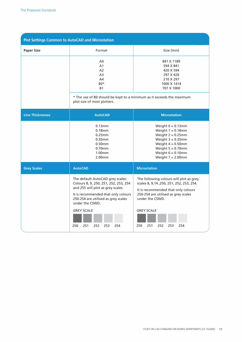
Plot Settings Common to AutoCAD and Microstation
Paper Size Format Size (mm)
A0 841 X 1189 A1 594 X 841 A2 420 X 594 A3 297 X 420 A4 210 X 297 B0* 1000 X 1414 B1 707 X 1000
* The use of B0 should be kept to a minimum as it exceeds the maximum plot size of most plotters.
Line Thicknesses AutoCAD Microstation
0.13mm Weight 0 = 0.13mm 0.18mm Weight 1 = 0.18mm 0.25mm Weight 2 = 0.25mm 0.35mm Weight 3 = 0.35mm 0.50mm Weight 4 = 0.50mm 0.70mm Weight 5 = 0.70mm 1.00mm Weight 6 = 0.10mm 2.00mm Weight 7 = 2.00mm
Grey Scales AutoCAD Microstation
The default AutoCAD grey scales: The following colours will plot as grey Colours 8, 9, 250, 251, 252, 253, 254 scales 8, 9,14 ,250, 251, 252, 253, 254. and 255 will plot as grey scales.
It is recommended that only colours It is recommended that only colours 250-254 are utilised as grey scales 250-254 are utilised as grey scales under the CSWD. under the CSWD.
GREY SCALE GREY SCALE
250 251 252 253 254 250 251 252 253 254
STUDY ON CAD STANDARD FOR WORKS DEPARTMENTS (CE 15/2000) 12
APP
LIC
ATI
ON
#1
The Proposed Standards
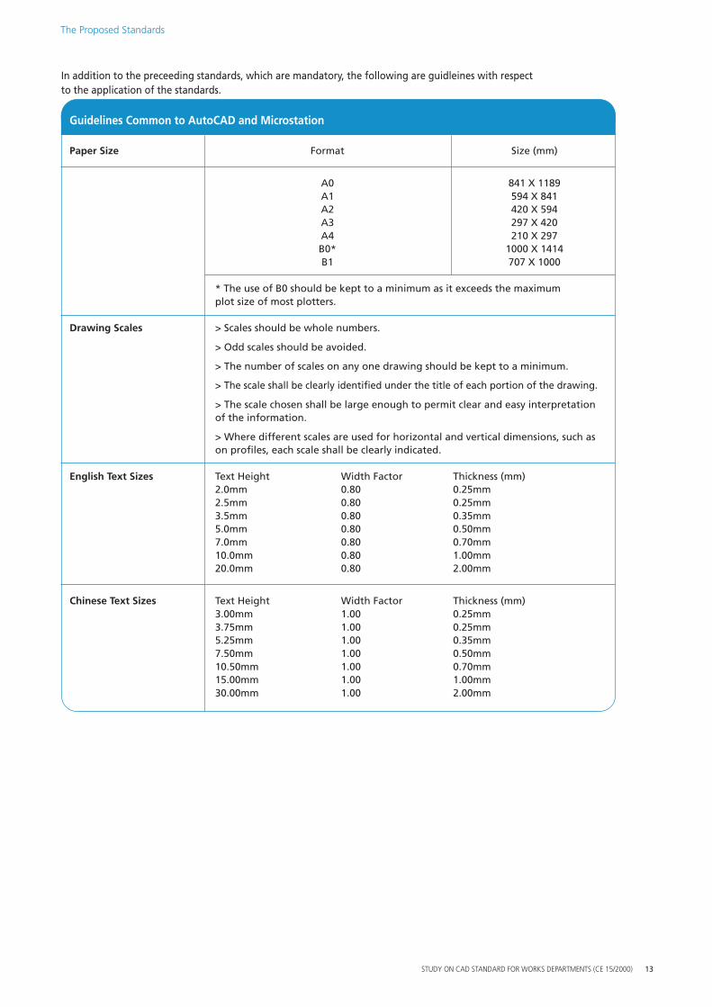
In addition to the preceeding standards, which are mandatory, the following are guidleines with respect to the application of the standards.
Guidelines Common to AutoCAD and Microstation
Paper Size Format Size (mm)
A0 841 X 1189 A1 594 X 841 A2 420 X 594 A3 297 X 420 A4 210 X 297 B0* 1000 X 1414 B1 707 X 1000
* The use of B0 should be kept to a minimum as it exceeds the maximum plot size of most plotters.
Drawing Scales > Scales should be whole numbers.
> Odd scales should be avoided.
> The number of scales on any one drawing should be kept to a minimum.
> The scale shall be clearly identified under the title of each portion of the drawing.
> The scale chosen shall be large enough to permit clear and easy interpretation of the information.
> Where different scales are used for horizontal and vertical dimensions, such as on profiles, each scale shall be clearly indicated.
English Text Sizes Text Height Width Factor Thickness (mm) 2.0mm 0.80 0.25mm 2.5mm 0.80 0.25mm 3.5mm 0.80 0.35mm 5.0mm 0.80 0.50mm 7.0mm 0.80 0.70mm 10.0mm 0.80 1.00mm 20.0mm 0.80 2.00mm
Chinese Text Sizes Text Height Width Factor Thickness (mm) 3.00mm 1.00 0.25mm 3.75mm 1.00 0.25mm 5.25mm 1.00 0.35mm 7.50mm 1.00 0.50mm 10.50mm 1.00 0.70mm 15.00mm 1.00 1.00mm 30.00mm 1.00 2.00mm
STUDY ON CAD STANDARD FOR WORKS DEPARTMENTS (CE 15/2000) 13
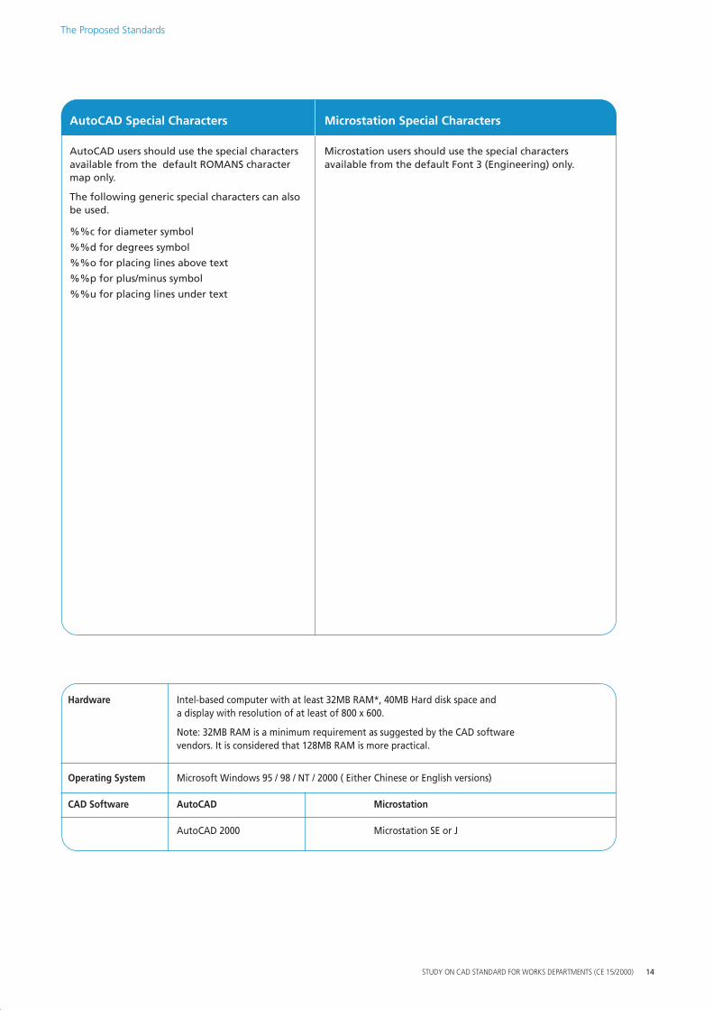
Hardware
SYST
EMEQ
UIR
EMEN
TSIntel-based computer with at least 32MB RAM*, 40MB Hard disk space and a display with resolution of at least of 800 x 600.
Note: 32MB RAM is a minimum requirement as suggested by the CAD software vendors. It is considered that 128MB RAM is more practical.
Operating System Microsoft Windows 95 / 98 / NT / 2000 ( Either Chinese or English versions)
CAD Software AutoCAD Microstation
AutoCAD 2000 Microstation SE or J
R
AutoCAD Special Characters Microstation Special Characters
APP
LIC
ATI
ON
#2AutoCAD users should use the special characters Microstation users should use the special characters
available from the default ROMANS character available from the default Font 3 (Engineering) only. map only.
The following generic special characters can also be used.
%%c for diameter symbol
%%d for degrees symbol
%%o for placing lines above text
%%p for plus/minus symbol
%%u for placing lines under text
The Proposed Standards
STUDY ON CAD STANDARD FOR WORKS DEPARTMENTS (CE 15/2000) 14
STUDY ON CAD STANDARD FOR WORKS DEPARTMENTS (CE 15/2000) 15
CSWD
CSWD
The Benefits of the CSWD Some of the benefits that the CSWD will bring to the participating departments and to stakeholders are described in this section.
The CSWD will meet the demand for CAD Standards
CAD is widely employed by the construction industry and has become the “tool of the trade” for drawing production. The communication of drawing information between Government and its consultants, contractors and suppliers will inevitably be in the form of CAD data. Demand for CAD drawings and hence a common CAD standard has increased substantially over recent years.
The CSWD will establish a communication platform for CAD data
The CSWD will meet the construction industry’s expectation that Government should take the lead in the formulation of CAD standards. The CSWD will establish a communication platform for CAD data, which is in line with the Construction Industry Review Committee’s recommendations contained in its report submitted to the Chief Executive in January 2001.
The CSWD will prevent data loss
The current situation, whereby many different CAD standards are used, results in information loss when data is transferred between parties. Data loss can typically occur through the use of different fonts and different line-styles. Incorrect transfer of Chinese text is also a common problem. The CSWD will minimise loss of data when transferred.
Environmental benefits
In order to avoid the problems that can occur through data loss due to different standards, hardcopy transfers are often used instead. It is the Government policy to promote environmental awareness and growing requirements for departments to minimise hard copies. This can effectively be achieved by asking consultants and contractors to submit drawings in digital form rather than in hardcopy. A common standard will facilitate data consistency and integrity in the exchange process and also enable efficient checking of drawings.
Improved Communication will result in better co-ordination
The CSWD will facilitate improved communications between the various parties involved in the construction industry. This increase in the amount of data transferred between disciplines and organisations will result in fewer errors due to poor translations, redraws of others’ data or even not having information available. This will all lead to improved co-ordination. When data can be properly structured and easily moved between disciplines then co-ordination will be greatly increased. The savings will not only come in the drawing office but also on site, where abortive work and delays due, for example, to clashes between services and structures, will be greatly reduced. The potential savings here are enormous.

CAD Data will be consistent throughout the life-cycle of a project
The ability to readily transfer data between the participating departments and the stakeholders, without effort-consuming post-processing will greatly encourage the re-use of the data throughout the life-cycle of a project. In practical terms, this means that graphic elements created in the early stages of a project will be re-used, without copying or being redrawn, through the whole life-cycle of the project, even through to facility management once the scheme is complete. This will not only provide benefits in terms of efficient drawing production but, more importantly, it will ensure greater accuracy as mistakes made in copying or recreating data will be avoided.
Data will be useable in other systems
The structuring of CAD data according to the proposed modified CI/SfB coding system together with an allowance for the addition of attribute data to the graphic elements will significantly increase the usefulness of the data for purposes such as quantities take-off and facility management. Efficiency increases in the work of associated disciplines such as quantity surveyors will result.
A structured library of drawing symbols will be provided
A comprehensive, rationalised and structured set of drawing symbols, covering all construction disciplines will be formed for use with the CSWD. The availability of these standard symbols will save time in users having to search for appropriate symbols or even create new symbols. In addition, confusion caused by the use of the same symbol for different elements or different symbols for the same element will be eradicated.
Improved efficiency will result from a common set of standards
While it is recognised that there will be a time and cost penalty in users familiarising themselves with the CSWD, once this initial hurdle is overcome then significant benefits will accrue. Users will not have to learn new standards for each Government project on which they work. Should CAD operators move between Government departments or other organisations then re-training will not be required.
Adherence with Standards will be made simple through a Standard Interface
It is intended to develop a Standard Interface under a subsequent activity to the CSWD Study. The purpose of the Standard Interface will be to cover all aspects of drawing production to the CSWD and be user-friendly, effective and efficient. The Standard Interface, which will be made available to all Stakeholders, will:
(a) address the common drawing operations; (b) provide icons, menus and commands for invoking the operations in a user-friendly, effective and
efficient manner; (c) ensure that its appearance and operation will be consistent across the CAD platforms used by
Participating Departments.
The Standard Interface will therefore be a significant aid in helping to ensure that drawings are produced to the standards in an efficient way. The SI will help to produce drawings ‘right first time’ in terms of adherence to the standards, particularly for inexperienced users. It should be noted that the CSWD are not very different from the standards already in use in the departments and the industry as a whole.
The Benefits of the CSWD
STUDY ON CAD STANDARD FOR WORKS DEPARTMENTS (CE 15/2000) 16
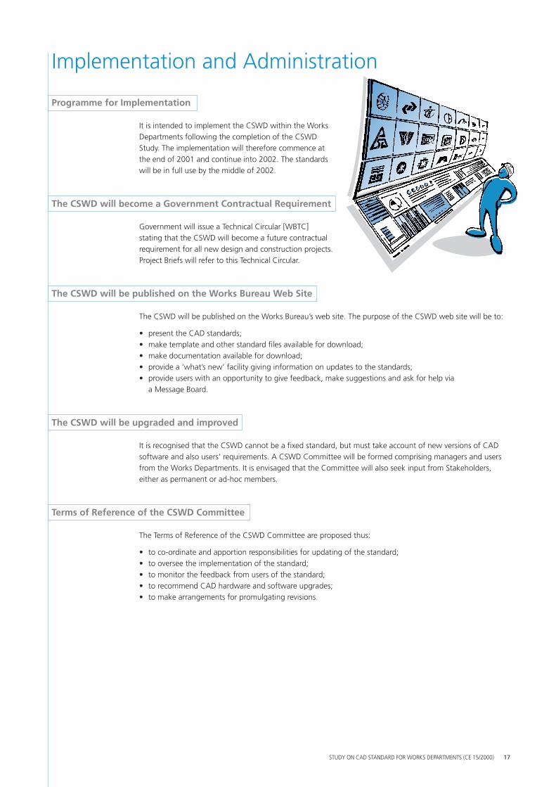
Programme for Implementation
It is intended to implement the CSWD within the Works Departments following the completion of the CSWD Study. The implementation will therefore commence at the end of 2001 and continue into 2002. The standards will be in full use by the middle of 2002.
The CSWD will become a Government Contractual Requirement
Government will issue a Technical Circular [WBTC] stating that the CSWD will become a future contractual requirement for all new design and construction projects. Project Briefs will refer to this Technical Circular.
The CSWD will be published on the Works Bureau Web Site
The CSWD will be published on the Works Bureau’s web site. The purpose of the CSWD web site will be to:
• present the CAD standards; • make template and other standard files available for download; • make documentation available for download; • provide a ‘what’s new’ facility giving information on updates to the standards; • provide users with an opportunity to give feedback, make suggestions and ask for help via
a Message Board.
The CSWD will be upgraded and improved
It is recognised that the CSWD cannot be a fixed standard, but must take account of new versions of CAD software and also users’ requirements. A CSWD Committee will be formed comprising managers and users from the Works Departments. It is envisaged that the Committee will also seek input from Stakeholders, either as permanent or ad-hoc members.
Terms of Reference of the CSWD Committee
The Terms of Reference of the CSWD Committee are proposed thus:
• to co-ordinate and apportion responsibilities for updating of the standard; • to oversee the implementation of the standard; • to monitor the feedback from users of the standard; • to recommend CAD hardware and software upgrades; • to make arrangements for promulgating revisions.
STUDY ON CAD STANDARD FOR WORKS DEPARTMENTS (CE 15/2000) 17
CSWD
Implementation and Administration

Element Coding
The CSWD require the categorisation of the elements that are contained within each file. This chapter contains details of the CSWD coding system that is to be used for categorising elements.
What are elements?
Elements are defined as: “The physical parts of construction and related works.” In addition, areas and spaces can be categorised as elements.
Why code elements?
One of the main objectives of the CSWD is to add intelligence to CAD data. In simple terms this means that lines that are drawn should be identifiable as the element that they represent, rather than just being lines. By being able to identify each element, then CAD data can be:
• easily manipulated; • transferred to other software packages (e.g. analytical, design and measurement); • enhanced by the addition of attribute data (facility management etc.)
Where is element coding used?
Element coding is used in the naming of:
• layers • symbol libraries
It can also be used as part of the file ID reference of model files.
The CSWD Element Coding System
The CSWD Element Coding System is based on the international CI/SfB coding system. This coding system is already in use in Hong Kong by the Architectural Services Department and by the Housing Authority. The original SfB system has been modified for use in the CSWD by expanding the categories relating to infrastructure works. The coding system can be broken down into:
10 ELEMENT DIVISIONS e.g. 6 - Electrical 100 MAIN CLASSES e.g 67 - Fire Services 1,000 CLASSES e.g. 674 - Smoke detection and alarm system 10,000 SUB CLASSES (potentially)
STUDY ON CAD STANDARD FOR WORKS DEPARTMENTS (CE 15/2000) 18

Element Coding
How to use the Element Coding System
The CSWD Element Coding Tables are given on pages 20 – 24. The tables are divided down to the 1,000 Classes of the system. Users are required to code elements at the Class level, i.e. to use a minimum of 3 digits. For example:
Coding will normally be by Class
Automatic Smoke Detection and Alarm Systems would be coded as 674_ Highway centre-lines would be coded as 811_ Straight stairs would be coded as 241_
The use of Grouped Classes is acceptable
It would be acceptable to code these three elements under their grouped category of:
Fire services 670_ Highways 810_ Stairs 240_
The decision whether to group or identify separately is left to the user and will depend on the amount of information being produced and the need for future manipulation.
The use of Sub Classes is at the user’s discretion
An underscore is placed in the fourth digit position when only three digits are used, as specified in the Standards. If required, Classes can be further sub-divided, at the user’s discretion into Sub Classes. In this case the fourth digit would be used. For example, users may wish to identify different types of seawall (956_) thus:
9561 Blockwork seawalls 9562 Wave absorbing seawalls 9563 Rock-faced sloping seawalls
Those classes that may require further sub-division into subclasses are shown with an asterisk* in the tables that follow.
The CSWD Element Coding system therefore provides flexibility as to the level of detail that is used.
STUDY ON CAD STANDARD FOR WORKS DEPARTMENTS (CE 15/2000) 19
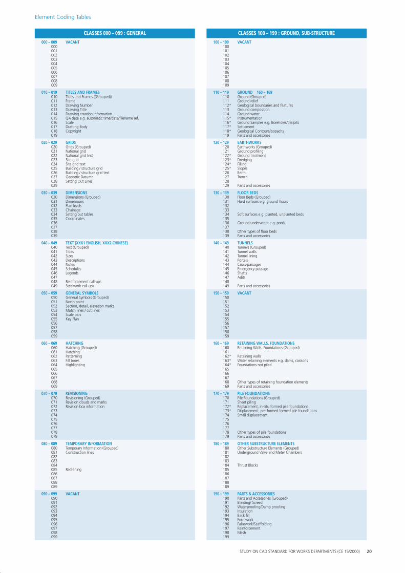
CLASSES 000 – 099 : GENERAL CLASSES 100 – 199 : GROUND, SUB-STRUCTURE
000 – 009 VACANT 100 – 109 VACANT 000 100 001 101 002 102 003 103 004 104 005 105 006 106 007 107 008 108 009 109
010 – 019 TITLES AND FRAMES 110 – 119 GROUND 160 – 169 010011
Titles and Frames ((Grouped)) Frame
110 111
Ground (Grouped) Ground relief
012 013 014 015016 017 018 019
Drawing Number Drawing Title Drawing creation information QA data e.g. automatic time/date/filename ref. Scale Drafting Body Copyright
112* 113 114 115* 116* 117* 118* 119
Geological boundaries and features Ground composition Ground water Instrumentation Ground Samples e.g. Boreholes/trialpits Settlement Geological Contours/Isopachs Parts and accessories
020 – 029 GRIDS 120 – 129 EARTHWORKS 020021 022 023 024 025026 027
Grids (Grouped) National grid National grid text Site grid Site grid text Building / structure grid Building / structure grid text Geodetic Datumn
120 121 122* 123* 124* 125* 126 127
Earthworks (Grouped) Ground profiling Ground treatment Dredging Filling Slopes Berm Trench
028 029
Setting Out Lines 128 129 Parts and accessories
030 – 039 DIMENSIONS 130 – 139 FLOOR BEDS 030031 032
Dimensions (Grouped) Dimensions Plan levels
130 131 132
Floor Beds (Grouped) Hard surfaces e.g. ground floors
033 034 035
Chainage Setting out tables Coordinates
133 134 135
Soft surfaces e.g. planted, unplanted beds
036 037
136 137
Ground underwater e.g. pools
038 039
138 139
Other types of floor beds Parts and accessories
040 – 049 040041
TEXT (XXX1 ENGLISH, XXX2 CHINESE) Text (Grouped) Titles
140 – 149 140 141
TUNNELS Tunnels (Grouped) Tunnel walls
042 043 044 045046 047
Sizes Descriptions Notes Schedules Legends
142 143 144 145 146 147
Tunnel lining Portals Cross-passages Emergency passage Shafts Adits
048 049
Reinforcement call-ups Steelwork call-ups
148 149 Parts and accessories
050 – 059 GENERAL SYMBOLS 150 – 159 VACANT 050051 052
General Symbols (Grouped) North point Section, detail, elevation marks
150 151 152
053 054
Match lines / cut lines Scale bars
153 154
055056
Key Plan 155 156
057 157 058 158 059 159
060 – 069 060061 062 063 064 065
HATCHING Hatching (Grouped) Hatching Patterning Fill tones Highlighting
160 – 169 160 161 162* 163* 164* 165
RETAINING WALLS, FOUNDATIONS Retaining Walls, Foundations (Grouped)
Retaining walls Water retaining elements e.g. dams, caissons Foundations not piled
066 166 067 167 068 069
168 169
Other types of retaining foundation elements Parts and accessories
070 – 079 REVISIONING 170 – 179 PILE FOUNDATIONS 070071 072 073 074 075
Revisioning (Grouped) Revision clouds and marks Revision box information
170 171 172* 173* 174 175
Pile Foundations (Grouped) Sheet piling Replacement, in-situ formed pile foundations Displacement, pre-formed formed pile foundations Small displacement
076 176 077 177 078 079
178 179
Other types of pile foundations Parts and accessories
080 – 089 TEMPORARY INFORMATION 180 – 189 OTHER SUBSTRUCTURE ELEMENTS 080081 082
Temporary Information (Grouped) Construction lines
180 181 182
Other Substructure Elements (Grouped) Underground Valve and Meter Chambers
083 183 084 184 Thrust Blocks 085086
Red-lining 185 186
087 187 088 188 089 189
090 – 099 VACANT 190 – 199 PARTS & ACCESSORIES 090091 092 093
190 191 192 193
Parts and Accessories (Grouped) Blinding/ Screed Waterproofing/Damp proofing Insulation
094 194 Back fill 095 195 Formwork 096 097
196 197
Falsework/Scaffolding Reinforcement
098 198 Mesh 099 199
Element Coding Tables
STUDY ON CAD STANDARD FOR WORKS DEPARTMENTS (CE 15/2000) 20
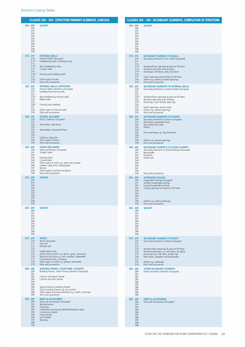
Element Coding Tables
CLASSES 200 – 299 : STRUCTURE PRIMARY ELEMENTS, CARCASS CLASSES 300 – 399 : SECONDARY ELEMENTS, COMPLETION OF STRUCTURE
200 – 209 VACANT 300 - 309 VACANT 200 300 201 301 202 302 203 303 204 304 205 305 206 306 207 307 208 308 209 309
210 - 219 EXTERNAL WALLS 310 - 319 SECONDARY ELEMENTS TO WALLS, 210 211*
External Walls (Grouped) Loadbearing walls including cavity
310 311
Secondary Elements to Ext. Walls (Grouped)
212 312 213* 214 215 216*
Non-loadbearing walls Curtain walls
Framing and cladding walls
313* 314 315* 316
Window/Door openings & parts to fill them Window openings and windows Doorways, entrances, exits and doors
217 218 219
Other types of walls Parts and accessories
317 318 319
Hatch openings and hatches to fill them Others e.g. barred, louvred openings Parts and accessories
220 - 229 INTERNAL WALLS, PARTITIONS 320 - 329 SECONDARY ELEMENTS TO INTERNAL WALLS 220 221*
Internal Walls, Partitions (Grouped) Loadbearing internal walls
320 321
Secondary Elements to Internal Walls (Grouped)
222 322 223* 224 225 226*
Non-loadbearing internal walls Baffle walls
Framing and cladding
323* 324 325* 326
Window/Door openings & parts to fill them Window openings and windows Doorways, room divider openings
227 228 229
Other types of internal walls Parts and accessories
327 328 329
Hatch openings, service voids Others e.g. barred openings Parts and accessories
230 - 239 FLOORS, GALLERIES 330 - 339 SECONDARY ELEMENTS TO FLOORS 230 231 232 233
Floors, Galleries (Grouped)
Monolithic, slab floors
330 331 332 333
Secondary Elements to Floors (Grouped) Secondary suspended floors Secondary floor beds Plinths
234 Assembled, composite floors 334 235 236
335 336
Floor openings e.g. trap doorways
237 Galleries, balconies 337 238 239
Other types of floors Parts and accessories
338 339
Others e.g. barred openings Parts and accessories
240 - 249 STAIRS AND RAMPS 340 - 349 SECONDARY ELEMENTS TO STAIRS & RAMPS 240 241
Stairs and Ramps (Grouped) Straight stairs
340 341
Secondary Elements to Stairs & Ramps (Grouped) Balustrades
242 342 Handrails 243 Dog leg stairs 343 Guide rails 244 Curved stairs 344 245 Other types of stairs e.g. open well, escape 345 246 Ladders, step irons, sliding poles 346 247 Ramps 347 248 Other types of vertical circulation 348 249 Parts and accessories 349 Parts and accessories
250 – 259 VACANT 350 – 359 SUSPENDED CEILINGS 250 251 252 253 254
350 351 352 353 354
Suspended Ceilings (Grouped) Jointless suspended ceilings Louvred suspended ceilings Ceiling openings and parts to fill them
255 355 256 356 257 357 258 259
358 359
Others e.g. ceiling walkways Parts and accessories
260 – 269 VACANT 360 – 369 VACANT 260 360 261 361 262 362 263 363 264 364 265 365 266 366 267 367 268 368 269 369
270 – 279 ROOFS 370 – 379 SECONDARY ELEMENTS TO ROOFS 270 271
Roofs (Grouped) Flat roof
370 371
Secondary Elements to Roofs (Grouped)
272 Pitched roof 372 273 274 275 276 277
Folded plate roofs Other roofs by form e.g. dome, spires, cylindrical Roofs by structure e.g. arch, vaulted, suspended Cantilevered roofs, canopies
373 374 375 376 377
Window/door openings & parts to fill them Window openings e.g. roof lights, sky lights Doorways e.g. trap door, access trap Roof eaves, parapets and balustrades
278 279
Other types of roofs e.g. gabled, retractable Parts and accessories
378 379
Others e.g. walkways Parts and accessories
280 – 289 BUILDING FRAMES, OTHER PRIM. ELEMENTS 380 – 389 OTHER SECONDARY ELEMENTS 280 281
Building Frames, other Primary Elements (Grouped) 380 381
Other Secondary Elements (Grouped)
282 Column and beam frames 382 283 Column and slab frames 383 284 384 285 385 286 Space frames as building frames 386 287 Other building frames e.g. pin-jointed 387 288 Other types of primary elements e.g. shafts, chimneys 388 289 Parts and accessories 389
290 – 299 PARTS & ACCESSORIES 390 – 399 PARTS & ACCESSORIES 290 291
Parts and Accessories (Grouped) Reinforcement
390 391
Parts and Accessories (Grouped)
292 Steelwork 392 293 Cables/Post tensioned cables/Prestressed cables 393 294 Connection details 394 295 Fixing details 395 296 Joint details 396 297 Bearings 397 298 398 299 399
STUDY ON CAD STANDARD FOR WORKS DEPARTMENTS (CE 15/2000) 21
Element Coding Tables
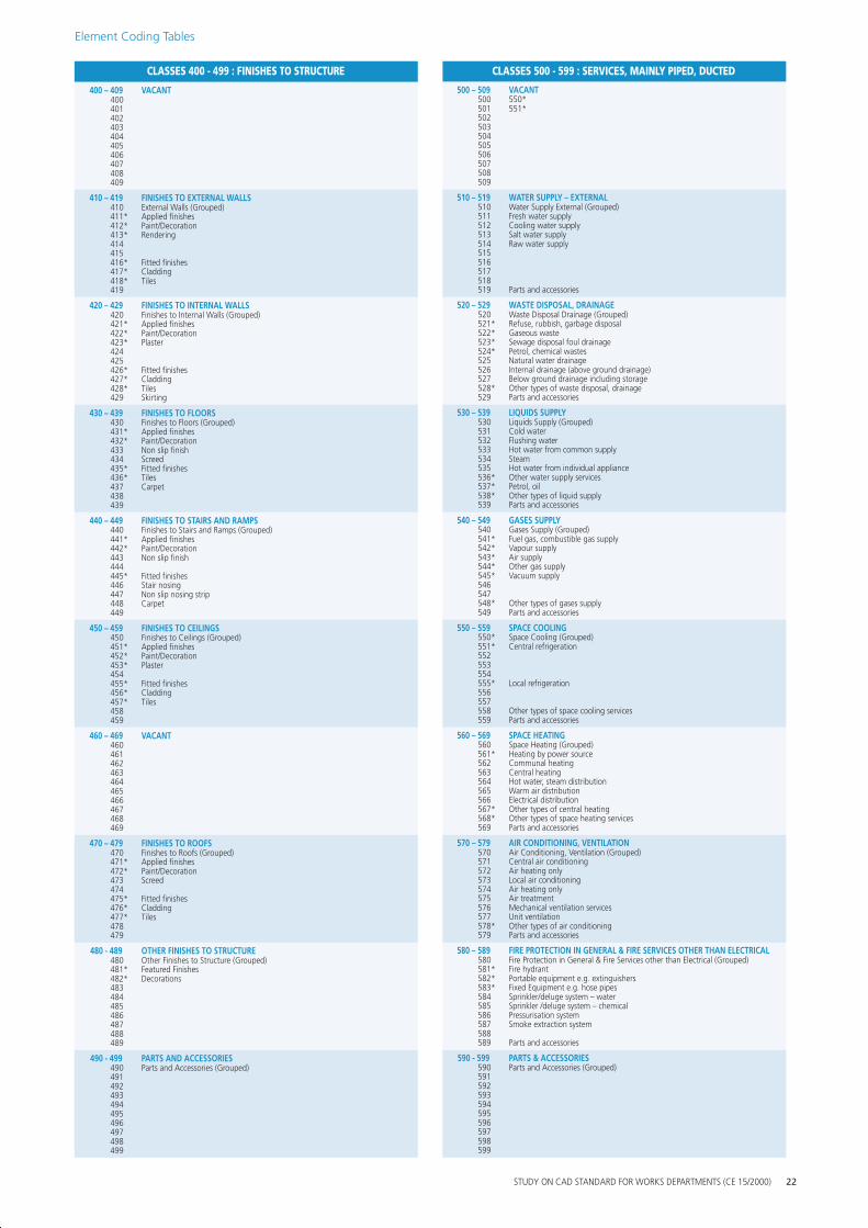
CLASSES 400 - 499 : FINISHES TO STRUCTURE CLASSES 500 - 599 : SERVICES, MAINLY PIPED, DUCTED
400 – 409 VACANT 500 – 509 VACANT 400 500 550* 401 501 551* 402 502 403 503 404 504 405 505 406 506 407 507 408 508 409 509
410 – 419 FINISHES TO EXTERNAL WALLS 510 – 519 WATER SUPPLY – EXTERNAL 410 411* 412* 413* 414 415
External Walls (Grouped) Applied finishes Paint/Decoration Rendering
510 511 512 513 514 515
Water Supply External (Grouped) Fresh water supply Cooling water supply Salt water supply Raw water supply
416* Fitted finishes 516 417* 418*
Cladding Tiles
517 518
419 519 Parts and accessories
420 – 429 FINISHES TO INTERNAL WALLS 520 – 529 WASTE DISPOSAL, DRAINAGE 420 421* 422* 423* 424
Finishes to Internal Walls (Grouped) Applied finishes Paint/Decoration Plaster
520 521* 522* 523* 524*
Waste Disposal Drainage (Grouped) Refuse, rubbish, garbage disposal Gaseous waste Sewage disposal foul drainage Petrol, chemical wastes
425 426* 427* 428* 429
Fitted finishes Cladding Tiles Skirting
525 526 527 528* 529
Natural water drainage Internal drainage (above ground drainage) Below ground drainage including storage Other types of waste disposal, drainage Parts and accessories
430 – 439 FINISHES TO FLOORS 530 – 539 LIQUIDS SUPPLY 430 431* 432* 433 434
Finishes to Floors (Grouped) Applied finishes Paint/Decoration Non slip finish Screed
530 531 532 533 534
Liquids Supply (Grouped) Cold water Flushing water Hot water from common supply Steam
435* 436* 437 438 439
Fitted finishes Tiles Carpet
535 536* 537* 538* 539
Hot water from individual appliance Other water supply services Petrol, oil Other types of liquid supply Parts and accessories
440 – 449 FINISHES TO STAIRS AND RAMPS 540 – 549 GASES SUPPLY 440 441* 442* 443 444 445* 446 447 448 449
Finishes to Stairs and Ramps (Grouped) Applied finishes Paint/Decoration Non slip finish
Fitted finishes Stair nosing Non slip nosing strip Carpet
540 541* 542* 543* 544* 545* 546 547 548* 549
Gases Supply (Grouped) Fuel gas, combustible gas supply Vapour supply Air supply Other gas supply Vacuum supply
Other types of gases supply Parts and accessories
450 – 459 FINISHES TO CEILINGS 550 – 559 SPACE COOLING 450 451* 452* 453*
Finishes to Ceilings (Grouped) Applied finishes Paint/Decoration Plaster
550* 551* 552 553
Space Cooling (Grouped) Central refrigeration
454 554 455* 456* 457*
Fitted finishes Cladding Tiles
555* 556 557
Local refrigeration
458 459
558 559
Other types of space cooling services Parts and accessories
460 – 469 VACANT 560 – 569 SPACE HEATING 460 461 462 463 464
560 561* 562 563 564
Space Heating (Grouped) Heating by power source Communal heating Central heating Hot water, steam distribution
465 565 Warm air distribution 466 566 Electrical distribution 467 468 469
567* 568* 569
Other types of central heating Other types of space heating services Parts and accessories
470 – 479 FINISHES TO ROOFS 570 – 579 AIR CONDITIONING, VENTILATION 470 471* 472* 473 474 475*
Finishes to Roofs (Grouped) Applied finishes Paint/Decoration Screed
Fitted finishes
570 571 572 573 574 575
Air Conditioning, Ventilation (Grouped) Central air conditioning Air heating only Local air conditioning Air heating only Air treatment
476* 477*
Cladding Tiles
576 577
Mechanical ventilation services Unit ventilation
478 479
578* 579
Other types of air conditioning Parts and accessories
480 - 489 OTHER FINISHES TO STRUCTURE 580 – 589 FIRE PROTECTION IN GENERAL & FIRE SERVICES OTHER THAN ELECTRICAL 480 481* 482* 483 484 485 486 487 488
Other Finishes to Structure (Grouped) Featured Finishes Decorations
580 581* 582* 583* 584 585 586 587 588
Fire Protection in General & Fire Services other than Electrical (Grouped) Fire hydrant Portable equipment e.g. extinguishers Fixed Equipment e.g. hose pipes Sprinkler/deluge system – water Sprinkler /deluge system – chemical Pressurisation system Smoke extraction system
489 589 Parts and accessories
490 - 499 PARTS AND ACCESSORIES 590 - 599 PARTS & ACCESSORIES 490 491
Parts and Accessories (Grouped) 590 591
Parts and Accessories (Grouped)
492 592 493 593 494 594 495 595 496 596 497 597 498 598 499 599
STUDY ON CAD STANDARD FOR WORKS DEPARTMENTS (CE 15/2000) 22
Element Coding Tables
CLASSES 600 – 699 : SERVICES, MAINLY ELECTRICAL CLASSES 700 – 799 : FITTINGS, FURNITURE AND EQUIPMENT (FFE)
600 – 609 VACANT 700 – 709 VACANT 600 700 601 701 602 702 603 703 604 704 605 705 606 706 607 707 608 708 609 709
610 – 619 ELECTRICITY SUPPLY 710 – 719 CIRCULATION FFE 610 611
Electricity Supply (Grouped) Radial distribution
710 711
Circulation FFE (Grouped) Signs, symbols
612 613 614
Ring main distribution Rising main distribution
712 713 714
Display fittings Access fittings Bollard/Cone/Barrier
615 715 Turnstiles 616 617 618* 619
Public mains supply Privately generated supply Other types of electrical supply services Parts and accessories
716 717 718* 719
Flag
Other types of circulation fittings Parts and accessories
620 – 629 POWER 720 – 729 REST, WORK FFE 620 621 622 623 624
Power (Grouped) High voltage system Medium voltage system Low voltage system
720 721 722 723 724
Rest, Work FFE (Grouped) Rest fittings Fittings for relaxation Work fittings
625 626 627
Uninterruptible power supply Battery power systems Power subcircuit
725 726 727
Benches, tables, seating, chairs
628 629
Power trunking/conduit Parts and accessories
728* 729
Other types of rest, work fittings Parts and accessories
630 – 639 LIGHTING 730 – 739 CULINARY FFE 630 631 632 633 634 635* 636 637 638* 639
Lighting (Grouped) General lighting Local lighting Emergency lighting Street lighting Airfield lighting Floodlighting Waterproof lighting Other types of lighting services Parts and accessories
730 731 732 733 734 735 736 737 738* 739
Culinary FFE (Grouped) Culinary work fittings Sink, disposal units, washing up machines
Culinary processing, cooking fittings Culinary storage fittings
Bar/Food counters, dining tables, seating Other types of culinary, catering fittings Parts and accessories
640 – 649 COMMUNICATIONS 740 – 749 SANITARY FFE 640 641* 642
Communications (Grouped) Visual including audio-visual
740 741 742
Sanitary FFE (Grouped) Sanitary suites Washing fittings
643* Audio 743 Drying fittings 644* 645 646
Signals other than visual or audio Synchronous clocks SCADA
744 745 746
Disposal fittings
647 747 Supply fittings 648* 649
Other types of communications services Parts and accessories
748* 749
Other types of sanitary, hygiene fittings Parts and accessories
650 – 659 VACANT 750 – 759 CLEANING FFE 650 750 Cleaning FFE (Grouped) 651 751 Washing fittings 652 752 653 753 Drying fittings 654 754 Pressing, Ironing fittings 655 755 656 756 657 757 658 758* Other types of cleaning, maintenance fittings 659 759 Parts and accessories
660 – 669 TRANSPORT 760 – 769 STORAGE, SCREENING FFE 660 661
Transport (Grouped) Lifts
760 761
Storage, Screening FFE (Grouped) Composite storage fittings
662* 663 664
Other types of internal lifts, hoists Travelling cradles Escalators
762 763 764
Cupboards fittings Drawers fittings Shelving, racking fittings
665* 666*
Conveyors/Travelators Cable car, Gondola, Chair lift
765 766
Suspended storage fittings Storage fittings with additional facility
667 Cranes 767 Screening fittings 668* 669
Other types of transport services Parts and accessories
768* 769
Other types of storage, screening fittings Parts and accessories
670 – 679 FIRE SERVICES ELECTRICAL 770 – 779 SPECIAL ACTIVITY FFE 670 671 672 673 674 675 676 677
Fire Services Electrical (Grouped) Audio/Visual fire alert system Automatic fire detection and alarm system Automatic heat detection and alarm system Automatic smoke detection and alarm system Manual fire alert system Automatic leakage detection and alarm system
770 771 772 773 774 775 776 777
Special Activity FFE (Grouped) Gymnasia/physical training facilities Fighting sports facilities One-to-one sports facilities e.g. squash Bowling alleys Athletics facilities Racing facilities Team ball games facilities
678 778 Equestrian facilities 679 779 Air sports facilities
680 – 689 SECURITY, CONTROL, OTHER SERVICES 780 – 789 OTHER FFE 680 681
Security, Control, Other Services (Grouped) 780 781
Other FFE (Grouped)
682 683
Security services 782 783 Soft furnishings including upholstery
684 784 685 785 686* 687 688* 689
Other security protection services Control services –process/monitoring Other types of security, control services Parts and accessories
786 787 788 789
Works of art
690 – 699 PARTS & ACCESSORIES 790 – 799 PARTS AND ACCESSORIES 690 691
Parts and Accessories (Grouped) 790 791
Parts and Accessories (Grouped)
692 792 Waste/Litter/Rubbish Bin 693 694 695
Earthing Protection Lightning protection
793 794 795
696 796 697 797 698 798 699 799
STUDY ON CAD STANDARD FOR WORKS DEPARTMENTS (CE 15/2000) 23
Element Coding Tables
CLASSES 800 – 899 : TRANSPORT INFRASTRUCTURE CLASSES 900 – 999 : EXTERNAL WORKS 800 – 809 GROUND SURVEY
800 Ground Survey (Grouped) 801 Survey control 802 Elevation Contours 803 Spot levels 804 805 806 807 808 Military Cable 809
810 – 819 HIGHWAYS 810 Highways (Grouped) 811 Centre-lines 812 Setting out lines 813 Carriageway edges 814 Shoulders 815 Verges 816 Footpaths 817 Cycle-tracks 818 Paved area 819 Parts and accessories
900 – 909 900 901 902 903 904 905 906 907 908 909
SITE PREPARATION Site Preparation (Grouped) Clearing/demolition Sign Board
Parts and accessories
910 – 919 BOUNDARIES & ENCLOSURES 910 Boundaries & Enclosures (Grouped) 911 Gazettal limits 912 Planning boundaries 913 Lot/Land allocation boundaries 914 Site boundaries 915 Works areas 916 Hoardings / fences / gates 917* Reserves 918* Swept paths / kinematic envelopes 919 Parts and accessories
820 – 829 STREET FURNITURE 820 Street Furniture (Grouped) 821 Safety features / Railing / Barriers 822 Weigh bridge 823 Toll gate 824 Speed humps 825 Vehicle stops 826 827 828 829 Parts and accessories
920 – 929 920 921 922 923 924 925 926 927 928 929
SURFACE WATER DRAINAGE Surface Water Drainage (Grouped) River/Stream/Ditch Culvert/Channel/Catchwater/Nullah Aqueduct Pipe Drain Manhole Catchpit Pump Parts and accessories
830 – 839 TRAFFIC AIDS & MARKINGS 830 Traffic Aids & Markings (Grouped) 831 Traffic signs 832 Markings 833 Directional signs 834 Traffic signals and equipment 835 Cats eyes/Reflective studs 836 Traffic Bollards 837 838 839 Parts and accessories
930 – 939 SEWERAGE 930 Sewerage (Grouped) 931 Pipe 932 Manhole 933 Sewer 934 Sewerage tank/Septic tank/Cesspools 935 Outfall 936 Sewage treatment plant 937 938 939 Parts and accessories
840 –849 RAILWAYS 840 Railways (Grouped) 841 Centre-lines 842 Setting out lines 843 Trackwork 844 Trackform 845 Tramways 846 847 848 Safety features / Railing / Barriers 849 Parts and accessories
850 – 859 BRIDGES 850 Bridges (Grouped) 851 Abutment 852 Anchor Block 853 Column 854 Pier 855 Tower 856 Deck 857 Parapet 858 Cable Support Systems 859 Parts and accessories
940 – 949 940 941 942 943 944 945 946 947 948 949
DUCTING (EXTERNAL) Ducting (Grouped) Ducts Access chambers Protective surround
950 – 959 MARINE WORKS 950 Marine Works (Grouped) 951 Bathymetric survey 952 Seabed contours 953 Breakwater 954 Dolphin 955 Floating jetty 956 Seawalls 957 Moorings / buoys 958 Fendering 959 Parts and accessories
860 – 869 GROUND SURFACE – AIRFIELDS 860 Ground Surface – Airfields (Grouped) 861 Centre-lines, setting out lines 862 Pavement edges 863 Shoulders 864 Pavement jointing 865 866 867 868 869 Parts and accessories
870-879 VACANT 870 871 872 873 874 875 876 877 878 879
960 – 969 960 961 962 963 964 965 966 967 968 969
MARINE FURNITURE Marine Furniture (Grouped) Notice board Bollard Handrail Pillar box Refuse containment room Seawall block Wave detector block Tetrapod
970 – 979 STRUCTURES IN EXTERNAL WORKS 970 Structures in External Works (Grouped) 971 Building outlines 972 Underground building outlines 973 Pylons/Antenna/Masts 974 975 Utility connection points 976 977 978* Noise barriers 979 Parts and accessories
880-889 VACANT 980 – 989 LANDSCAPING 880 980 Landscaping (Grouped) 881 981* Hard landscaping 882 982* Soft landscaping 883 983* Features eg. Sculptures / water features 884 984* Landscaping structures e.g. shade structure 885 985 886 986 887 987* Sports facilities 888 988 889 989
990 – 999 EXTERNAL WORKS PARTS & ACCESSORIES 990 Parts and Accessories (Grouped) 991 992 993 994 995 996 997 998 999
890 – 899 TRANSPORT INFR. PARTS & ACCESSORIES 890 Parts and Accessories (Grouped) 891 Reinforcement 892 Steelwork 893 Post tensioned cables/Prestressed cables 894 Connection details 895 Fixing details 896 Joint details 897 Bearings 898 899
STUDY ON CAD STANDARD FOR WORKS DEPARTMENTS (CE 15/2000) 24