Embed Size (px)
Citation preview

The Global File System t
Steven R. Soltis, Thomas M. Ruwart, Matthew T. O'Keefe
Department of Electrical Engineeringand
Laboratory for Computational Science and Engineering
University of Minnesota4-174 EE/CS Building
Minneapolis, MN 55455soltis @ee.umn.edu
Tel: 612-625-6306
Fax: 612-625-4583
Abstract
The Global File System (GFS) is a prototype design for a distributed file system in which
cluster nodes physically share storage devices connected via a network-like FibreChannel. Networks and network-attached storage devices have advanced to a level of
performance and extensibility so that the previous disadvantages of shared diskarchitectures are no longer valid. This shared storage architecture attempts to exploit the
sophistication of storage device technologies whereas a server architecture diminishes adevice's role to that of a simple component. GFS distributes the file system
responsibilities across processing nodes, storage across the devices, and file systemresources across the entire storage pool. GFS caches data on the storage devices insteadof the main memories of the machines. Consistency is established by using a locking
mechanism maintained by the storage devices to facilitate atomic read-modify-write
operations. The locking mechanism is being prototyped on Seagate disk drives and
Ciprico disk arrays. GFS is implemented in the Silicon Graphics IRIX operating systemand is accessed using standard Unix commands and utilities.
Introduction
Distributed systems can be evaluated by three factors: performance, availability, and
extensibility. Performance can be characterized by such measurements as response time
and throughput. Distributed systems can achieve availability by allowing their working
components to act as replacements for failed components. Extensibility is a combination
of portability and scalability. Obvious influences on scalability are such things as
addressing limitations and network ports, but subtle bottlenecks in hardware and software
may also arise.
These three factors are influenced by the architecture of the distributed and parallel
systems. The architectures can be categorized as message-based (shared nothing) and
1 This work was supported by the Office of Naval Research under grant no. N00019-95-1-0611, by theNational Science Foundation under grant ASC-9523480, and by grant no. 5555-23 from the UniversitySpace Research Association which is administered by NASA's Center for Excellence in Space Data andInformation Sciences (CESDIS) at the NASA Goddard Space Flight Center.
319
https://ntrs.nasa.gov/search.jsp?R=19960052744 2018-08-21T20:11:13+00:00Z

shared storage (shared disk) Message-based architectures share data by communication
between machines across a network with the data stored locally on devices within each
machine. Machines in the shared storage architecture access all storage devices directly.Figures 1 and 2 show examples of message-based and shared storage architectures [1][2].
Client Client Client Node Node Node
ork or I/0 Bus
Server Server Storage Controller Storage Controller
Figure 1: Message-Based Figure 2: Shared Storage
Advocates of both architectures claim the advantage with respect to these three factors.
This is a techno-religious war that will not be resolved any time soon, yet analyzingexisting systems gives perspective on the strengths and weaknesses of each architecture.
This next section summarizes a number of distributed file systems based on their datasharing approaches.
Message-based Distributed File Systems
Sun Network File System
The Sun Network File System (NFS) was designed by Sun Microsystems in 1985 [3].
It's design goals were system independence, name transparency, and preservation of Unix
file system semantics. NFS uses a client-server approach. The server is stateless andwrites modified data to stable storage before returning results. The server is able to cache
data in its system memory to improve performance. The clients make requests to the
server with all information necessary to complete the operation. Clients and servers
communicate over a network using remote procedure calls (RPC). The RPC is a high
level protocol built upon User Datagram Protocol (UDP) and Internet Protocol (IP).
The statelessness of the server eases crash recovery. A client that goes down does not
effect the operations of the server or other clients. A server that fails need only to reboot.
The clients will resend requests when the server has not completed their requests in agiven time. The clients perceive the server as being slow but they are unaware that it hasrebooted.
320

Sprite File System
Sprite is a distributed operating system for networked workstations developed under the
Symbolic Processing Using RISCs (SPUR) research project [4]. Like Sun NFS, Sprite
uses remote procedure calls to communicate across its network. Sprite's file system isdistributed across multiple servers and clients. It's primary goal was to provide name
transparency while still providing adequate performance. Even device special files are
accessible to any process on the network.
The Sprite file system maintains cache consistency using a server-initiated approach.The server tracks open files. When files are non-write-shared, the clients may cache the
portions of a file within their local memories. When a file moves from non-write-sharedto write-shared, the server performs a call-back operation and disables client caching.
Andrew and Coda File Systems
Carnegie Mellon University's Coda is a distributed file system descended from theAndrew file system which was a joint research project between IBM and CMU [5][6].
Both file systems are designed to operate on a distributed network of workstations scaling
up to 5000 machines.
Coda (constant data availability) was designed to improve on the availability of Andrew.Each client is able to cache entire files locally in its memory and disks. Furthermore,
multiple copies of each file may exist on several servers. A server failure may then have
little impact on availability. This approach also allows clients to run in disconnectedoperation using only the files it has cached locally. The client can reconnect to the
network and synchronize its cache with the rest of the system.
Like the Sprite file system, Coda servers maintain state concerning file accesses. The
servers are responsible for performing call-backs when a clients cached data has been
modified by another client. File sharing on a client is guaranteed to have consistency
described by Unix file sharing semantics. Files shared across different systems seeconsistency at the granularity of the entire file.
xFS Serverless Network File System
The xFS file system is part of the Berkeley's Network of Workstations (NOW) project
[7]. It is a successor to some of the research from the Sprite project. It uses a log
structured approach like Sprite's Log-structured File System (LFS) and Zebra's [8]
striping technique to simplify failure recovery and provide high throughput transfers.
321

In xFS workstations are connectedby a fast, switched network, xFS is said to beserverless,sincethestorageserverfunctionality canbeplacedon thesamemachinesasaclient. Hence, any system can managecontrol, metadata,and real data. This hasadvantagesof loadbalancing,scalability,andhigh availability.
Like Sprite,thesystemsupportsdatacachingon theclients[9]. The client requestsdatafrom a manager.This managertries to satisfy the requestfrom anotherclient's cache;otherwiseit directs the client the appropriatestoragedevice, xFSusesa tokenbasedcacheconsistencymechanism.A client mustacquireatoken for eachfile systemblockthatit wishesto modify. The managersnotify theclientsto invalidatetheir stalecopiesof thedataandforwardtheir requeststo thenewownerof thetoken.
Shared Storage Distributed File Systems
Digitars VAXClusters VMS
The VAXcluster is a "closely coupled" structure of VAX computing and storage nodes
that operates as a single system. This system had VAX nodes connected by a message-based interconnect. Each processor runs the same copy of the distributed VAX/VMS
operating system. The interconnection network had two topologies: the highperformance Star Coupler hub that supported a maximum of 16 devices and a low costEthernet network [ 10].
The storage devices are connected to the system through a Hierarchical StorageController (HSC). For high-reliability, another HSC could be placed between the dual
ported storage devices and the star coupler by adding a redundant path between the CPUsand the storage devices.
The operating system allows files to be shared using the cluster's distributed lockmanager. Lock requests are made for a particular access mode: exclusive access,
protected read, concurrent read, or concurrent write. Incompatible requests for resourcesare queued until the resource is unlocked. This system is a shared storage architecture,
since all file requests are serviced from the shared HSCs. Each HSC can support up to 32disks.
VMS allows caching for data and file system resources. Coherence is maintained
between the CPU's local memories by sequence numbers within the files' synchronization
locks. When the file system modifies a block, it increments the sequence number in the
file's lock. If another system has this block cached and later references it, this system willfind that it's sequence number is old. The block will be refreshed from the HSC.
322

Cray's Serverless File System
Cray Research's Serverless File System (SFS) is a file system incorporated in their
UNICOS operating system [11]. The file system uses a HIPPI disk array as the shared
storage device. The disk array is connected to four C90 machines through a HIPPIswitch. All C90 machines (nodes) act as peers; there is no server machine.
Arbitration of the HIPPI disk array is performed on a Sun SPARC workstation which isalso connected to the HIPPI switch. This workstation, call the HippiSeMaPhore (HSMP)
is responsible for maintaining semaphores used for mutual exclusion of data stored on the
disk array. It also has error recovery functions.
Cray's SFS supports two types of file operations: multiple readers and single writer. SFS
provides consistency by using the semaphores to facilitate read-modify-write operationsas well as limiting the open file states. Nodes are able to cache data like a local file
system but with the constraints of more limited parallel file operations.
Message--based Versus Shared Storage
The message-based architecture's strength lies in its extensibility. The approach is asportable as the network protocol connecting the machines and it can potentially scale to
large numbers of machines. The best example of message-based portability is NFS. This
file system dominates the industry, because it is available on almost every platform. File
systems like Coda have shown that the message-based approach scales to thousands ofmachines.
Message-based systems may perform well if data access is well balanced across allmachines. Load balancing is difficult since machine capacities and usage differ
dynamically across the system. Locality is also difficult to maintain, since there will
always be resources that are shared by many nodes in the system. Redundant copies canbe maintained but at the cost of coherence overheads. Furthermore, the performance
benefit of high speed devices like disk arrays is negated, since the bandwidth to each
machine is limited by the network. To summarize, achieving good performance on
message-based systems is not an easy task.
Server and device failures are another challenging problem facing the message-based
approach, since a server failure may result in data becoming inaccessible. Fault tolerance
may be maintained using disk array devices at each node, but redundancy is not extendedacross machines. Software redundancy schemes must be built into the file system to
maintain any fault tolerance.
The shared storage approach has the advantage that every machine has nearly uniform
access to all storage devices and freedom from servicing data requests from other
323

machines. This approachis similar to the traditional uniprocessormodel where amachineacts independently. Also, failures of a machinehave little effect on othersystemsexceptfor possibleloadincreases.Storagedeviceavailability canbe improvedusinghardwareRAID [12].
The sharedstoragearchitecturetakes advantageof the propertiesof the underlyingstoragehardware. Sinceeverynodehasuniform accessto thedevices,the bandwidthproducedby disk arraysor disk striping can be utilized by all nodes. Also, devicescapableof commandqueuingcanoptimizeheadseeksto providehighthroughput.
Thedownfall of traditionalsharedstoragesystemhasbeenscalabilityandcost. Systemslike the Digital's VAXcluster and Cray's SFSarebasedon proprietarynetworksandhardware. Proprietaryhardwaredoesnot benefit from market competitionand oftenremainscostly. Furthermore,thesesystemsdo not scalewith the numberof nodes. Inboth examples,only one storagedevice and a few machinescan be attachedto thesystem.
Sofar neitherarchitecturefully satisfiesall threefactors- performance,availability, andextensibility but new network technologiesare changing this. For instance, Fibre
Channel (FC) is an emerging ANSI and International Standards Organization (ISO)
standard for a network architecture [13] that supports network attached storage by
including the SCSI-3 channel protocol. Fibre Channel provides two topologies fornetwork attached storage: switched and arbitrated loop [14].
A high speed network like Fibre Channel can improve the performance of both shared
storage and message-based architectures, yet it does little to improve the extensibility andavailability of the message-based approach. Providing network attachment to storagedevices greatly enhances the extensibility of shared storage. With a network like Fibre
Channel, a system that is non-propriety and portable can be built using the shared storagearchitecture.
Existing shared storage systems must be redesigned to exploit the properties of thesenetworks and devices. The assumptions that traditional shared storage file systems made
with respect to data caching, coherence, and resource management are obsolete. For
instance, Cray's SFS caches data locally on its nodes to exploit the high bandwidth, low
latency memories of the C90s. This caching comes at the price of allowing only non-write-shared file operations. That is, if the file is opened by one or more readers, a writercannot access it until all readers close the file. This coherence mechanism can lead to
large latencies and even starvation.
324

The Global File System
The Global File System is a prototype design for a distributed file system. Network
attached storage devices are physically shared by the cluster nodes. The GFS prototype
is implemented in the Silicon Graphics' IRIX operating system [15][16] under the VFS
interface and is accessed using standard Unix commands and utilities [17][18][19]. The
machines and storage devices are connected via a Fibre Channel network.
GFS views storage as a Network Storage Pool (NSP) -- a collection of network attached
storage devices logically grouped to provide node machines with a unified storage space.
These storage pools are not owned or controlled by any one machine but rather act as
shared storage to all machines and devices on the network. NSPs are divided into
subpools where each subpool takes on the attributes of the underlying hardware.
GFS targets environments that require large storage capacities and bandwidth such asmultimedia, scientific computing, and visualization [20][21]. These large capacities
influence tradeoffs, such as caching and the metadata structure, associated with the
design of a file system.
Chip integration has transformed storage devices into sophisticated units capable ofreplacing many of the functions performed by a server machine in a client-server
environment. These devices can schedule accesses to media by queuing multiple
requests. They possess caches of one or more Megabytes that can be used for read and
write caching and prefetching.
GFS caches data in the nodes' main memories only during I/O request processing. After
each request is satisfied, the data is either released or written back to the storage devices.
To exploit locality of reference, GFS caches data on the storage devices. GFS informsthe devices on each request what data is appropriate to cache - such as metadata that is
accessed repetitively and small files like directories which are frequently accessed.
Consistency is established by using a locking mechanism maintained by the storage
devices to facilitate atomic read-modify-write operations. This form of locking has the
simplicity of a centralized mechanism yet is distributed across a large number of devices.
Figure 3 represents an example of the GFS distributed environment. The nodes are
attached to the network at the top of the figure and the storage pool at the bottom.
Connecting the nodes and the devices is a Fibre Channel network which may consist of
switches, loops, and hubs. In the example, three different subpools exist:/'single is a
single disk,/wide is a striping of several disks, and the/fast is a disk array.
325

GFS Node
GFS Node
CPU Memory Disk GFS Node /NFS Server
Backup , _Channel Ne_
IO---O__;.Switches, Hubs, and _
/single /wide / fast
Network Storage Pool
Figure 3: GFS Distributed Environment
To the figure's left is a tape device which is directly connected to the network. Such a
tape drive may be used for data backup or hierarchical storage management. A node
could initiate third party transfers between the disk devices and the tape drive. The figure
also shows how a GFS host can act as a NFS server. This ability allows machines
without GFS capabilities to access GFS data via an NFS exported file system. The
operating systems VFS interface handles the translation between GFS and NFS.
File System Structure
Each GFS file system is divided into several Resource Groups (RG). Resource groupsare designed to distribute file system resources across the entire storage subpool. Figure
4 shows the logical structure of a file system. Multiple RGs exist per device and can be
striped across several devices.
Resource groups are essentially mini-file systems. Each group has a RG block, data
bitmaps, dinode bitmaps (used as the dinode free list), dinodes, and data blocks. The RG
block contains information similar to what traditional superblocks maintain: the number
of free dinodes, the number of free data blocks, and the access times of the RG. File data
and metadata may span multiple groups.
326

GFS also has a superblock which contains information that cannot be distributed across
the resource groups. This information includes the number of nodes mounted on the file
system, bitmaps to calculate unique identifiers for each node, and the file system blocksize. The superblock also contains a static index of the RGs. This RG index describes
the location of each group as well as the group attributes and layout.
A GFS dinode takes an entire file system block. Each dinode is divided inlo a header
section which contains standard dinode fields and a section of pointers. The number of
pointers in a dinode is the determined by equation 1 and the number of pointers an
indirect block has is given in equation 2.
# pointers in dinode
file system block size - size of dinode header
= ...................................................... (1)size of block address
# pointers in indirect block =file system block size..........................
size of block address(2)
Dev_ LockI Super BlockwithResource Index
' [I ...............................', ',1..............................I! 2 / ',....II Res°urcoBIock'O u ilResourceBIock" I I::0 I RosourcoBlock-n
'1 ' 1 I 'i: . . i: . ii DIn_e Bltmaps =j i Din_e Bltmaps ::: i Di_e BRm_s
'1 ' '1 I.....i _ I ::! i
i Data Block Bitmaps i Data Block Bitmaps : un i Data Block Bitmaps
1 ' 1 ' JI ,i k[ ..... i } : [ ill
Device Loc :. l i
n+2 "'_ Dinode - 0 0 i Dinode - w+l i D node - x+l
0 ,;;,i : ° ;-;i;;;i;;;i :! •IDevicekock_I I ,
a !1°'=°"I'i11 Data Block- 0 I',I I1
|
Oi :JI Il I Data Block- q .ii ]1 ....... r
I
Resource Group - 0
, I _DeviceLock]l Dinode - x !: J /
i I_ c nData Block- q+l I::;
i i
i l: !: o:: !
• ..... Ii : ::
, Ii Data Block - r I,{
, |::7,''
Resource Group - 1
I
Resource Group - n
Figure 4: GFS Structure
327

The pointersform a tree structurein which all datablocks areat thetree'sleaves and
have the same height. This structure is used so that all its accesses require the samenumber of indirect accesses to the data blocks regardless of the offset into the file. This
structure differs from the traditional Unix file system (UFS) where data blocks might
have different heights. The UFS tree is simpler to implement yet can require an
additional level of indirection. Furthermore, UFS places multiple dinodes per file system
block. By taking an entire block, the GFS can have hundreds of direct pointers in thedinode instead of just ten as in a UFS dinode. Figure 5 illustrates a GFS dinode and one
level of indirection for referencing the data blocks.
GFS Dinode Indirect Blocks Data Blocks
• Dinode Number
• Resource GroupNumber
• File Type• Mode
• Owner/Group
• Number of Links
• Access Times
• Bookkeeping Info
Figure 5: GFS Dinode
Device Locks
Device Locks are mechanisms for node machines to maintain mutual exclusion of file
system data. They are implemented on the storage devices and accessed with a single
SCSI command. The Dlock command instructs the devices to perform primitive
operations on the locks - test and set and clear. The implementation of the device locks
on the device are limited by the following constraints:
1. The device lock commands are independent of all other SCSI commands.
2. Devices supporting device Locks have no awareness of the nature of data or resourcethat is locked for mutual exclusion.
328

3. Each lock requires minimal amounts of device memory - as little as one byte per lock.
Lock States
The state of each lock is described by one bit. If the bit is set to 1, the lock has been
acquired and is owned by a machine node. If the bit is 0, the lock is available to be
acquired by any node. The Dlock command action test and set first determines if thelock value is 1. If value is 1, the command returns with a status indicating that the lock
has already be acquired. If the value is 0, Dlock sets the lock to 1 and returns a good
status to the initiator. The Dlock command clear simply sets the lock bit to 0.
Clocks
Associated with each lock is a clock. The clocks are logical clocks in the sense that they
do not relate to time but instead keep an ordering of events for each lock. These clocks
are incremented when a successful action is performed. The clocks are used to monitor
how often a lock is accessed; i.e., how many times the lock has been set and then cleared.Such a clock gives insight into load balancing hot-spots. These occur when some locks
are accessed more often than others. More importantly, these clocks are useful for error
recovery.
The clocks are implemented using a minimal amount of memory -- typically 7 to 16 bits
each. The initiators must be aware that the clock values periodically roll-over from theirmaximum value to zero. This may happen several times a second on a highly accessed
lock, so care should be taken by the initiator not to assume that the clock value is slowly
growing. The clock value is returned after each Dlock command.
Device Failures
The device locks and their accompanying clocks are stored in volatile memory on the
device, although the locks are held across SCSI resets. When a device is powered on or afailure occurs which results in the locks being cleared, the device notifies all nodes by
setting Unit Attention. Upon finding a unit attention, a node checks to see if its locks arestill valid. Before proceeding, it will then re-acquire any locks that may have been lost.
Node Failures
A node that fails could leave device locks in the locked state indefinitely. These locks
will remain in this state until some node clears them. A node attempting to acquire a lock
that is owned by a failed node can identify that the lock has been untouched by checking
the activity of the lock's clock. If the clock has remained unchanged for an extended time
period, a node can identify such a case and clear the lock.
329

Caremustbetakenby thenodeclearingalock that it doesnotown. The true owner may
have failed or it may be in a hung state from which it will eventually return still believingit owns the lock. Furthermore, two separate nodes may simultaneously identify the same
lock which must be cleared and send resets. It may be possible that the first node clears
the lock and sets the lock in the following command. The second node which has already
decided to clear the lock sends the command after the lock has been acquired by the first
node. This second clear request must be ignored.
When a node wishes to clear a lock as failure recovery, the device compares the current
clock with the input clock from the node. This test ensures that the lock will only be
cleared if the node can identify the current value of the clock.
Deadlocks and Starvation
Deadlocks are avoided by the file system. The file system only acquires locks in anincreasing order. Circular dependencies are avoided. Starvation is handled by the filesystem and device drivers. The file system does not hold locks for more than a few I/O
requests to storage. A node's device drivers test for its own starvation by checking the
activity of the lock-based clock values. The node can increase the rate at which lock
requests are performed an in attempt to feed its starvation.
Consistency and Caching
Consistency is maintained by using atomic operations guaranteed by the device locks
when modifying data. Given the limited number of practical device locks per device - on
the order of 1024 - individual locks cannot be assigned to each file. One lock is assignedto the super block, one lock is assigned to each resource group, and the remaining locks
are divided among the dinodes. Figure 4 shows how device locks are associated with thesuperblock, resource groups, and dinodes.
When device locks are not implemented on the storage device, the SCSI commands
Reserve and Release can be used to perform atomic operations on data. These commands
provide exclusive access to the entire device for one node by not servicing requests fromother nodes. These commands guarantee exclusive access but do not provide much
parallelism. With only one reservation per device, many non-conflicting requests have to
wait until the storage device is released. In a distributed environment, such limited
access decreases system throughput and response times.
The SCSI protocol describes the optional commands Reserve and Release on Extents.
These commands allow initiators to reserve for exclusive access only the data blocks that
they may need. These commands decrease the granularity of exclusion from the device
level to the block level. While potentially increasing the throughput of the distributed
system, Reserve and Release on Extent commands require the devices to maintain
330

complicatedstatesof accesspermissions.For this reason,thesecommandsaregenerallynot implementedby themajority of devicemanufacturers.
We presentdevicelocksasa mutualexclusionmechanismthat is highly parallel,haslowdeviceoverheads,andrecoversfrom failuresgracefully. TheDlock commandis beingprototypedonSeagatediskdrivesandCipricodiskarrays.
Preliminary Results
Preliminary measurements have been taken with parallel SCSI hardware instead of Fibre
Channel. Fibre Channel hardware is not yet available to us, so we present the parallel
SCSI results instead. We hope to have Fibre Channel measurements by the time this
paper is presented. These results are based upon tests using SCSI Reserve and Release tomaintain consistency instead of device locks. The Dlock command is still in
development and testing by Ciprico and Seagate.
Test Configuration
These tests were conducted on three SGI Indys running IRIX 5.3 operating system. One
Indy has a 100 MHz R4600 processor while the other two have 132 MHz R4600processors. All machines have 32 Mbytes of main memory.
A Seagate Barracuda 2LP was used as the shared storage device. The 2LP is a 2
Gigabyte Fast SCSI-2 drive. It has a 17 millisecond maximum seek time and a 7200
RPM spindle speed. Our tests measured the time for reserve and release commands to beapproximately 2 milliseconds. This disk and all three system disks share the common
bus. The disk caching parameters are set at their default values.
The configuration shown in figure 6 is a representation of the test environment. To
overcome cabling difficulties, the system disk of node 2 was attached to the internal SCSIbus of node 0 and node 2's controller was directly connected to the internal bus of node 1.
All devices and controllers are electrically connected.
331

Node 0 System Disksfor Nodes 0 and 2
SCSI ID 4 and 7
IFast SCSI-2 Bus
Node 1 System Diskfor Node 2
SCSI ID 3
0!1
I/
_ _ Shared Disk
SCSIJ ID 5
Figure 6: GFS Test Environment
Node 2
Benchmarks
Small benchmark programs were run on one, two, and all three machines to study how
effectively the SCSI bus and disk are shared. The tests were run on the file systemrunning in user space as opposed to running under the VFS interface of the kernel. The
user level file system allows for easy tracing and performance measurements. The user
level file system adds various overheads to the system, so we believe that the VFS filesystem will perform even better.
The benchmarks chosen involve tests of creating, writing, and reading files. The file
sizes range from 1 Mbyte to 16 Mbytes. Files were written and read by making from 1 to
128 requests per file. A delay was placed between each request ranging from zero to one
second. This delay represents the time for which a real application would performcomputation or wait for some reason other than I/O. All tests were run five times so that
the median values could be used to evaluate the performance. Table 1 summarizes these
benchmarks. The benchmarks chosen for these tests attempt to match the performancecapabilities of the single shared disk and 10 MB/sec SCSI bus. These benchmarks will
be scaled appropriately when performing the tests on Fibre Channel hardware withmultiple devices.
332

Parameter Range
Number of Nodes
TypesFile Sizes
Number of Requests per File
Delay Between Requests
1,2,3Create and Write, Write, Read
1 MB to 16 MB
1 to 128
0 ms, 100 ms, 500 ms, 1000 ms
Table 1: Benchmark Parameters
Parallel SCSI Performance
Figures 7 and 8 show the speedups for each machine creating and reading a 1 MB file in128 KB requests, respectively. Figures 9 and 10 show the speedups where machines
create and read a 16 MB file in 1 MB requests, respectively. These results are scaled to
reflect equal amounts of work of 3 MB and 48 MB respectively. That is, the time for one
machine is multiplied by 3 and the time is multiplied by 1.5 for two machines. All these
times are then normalized to the one machine test by dividing by the one machine time.
Curves are given for no delay and 100 ms, 500 ms, and 1000 ms delays. The write testsshow trends similar to the read tests.
Figures 1 l, 12, 13, and 14 are plots of the 16 MB creates with varying request sizes.
Figures 15, 16, 17, and 18 are plots of the same test with read requests. The request axis
is the number of requests needed to access the entire file. The three curves for each plotare the time for one machine alone, the time of the slowest machine with three machines
running simultaneously, and three times the one machine time. This last curve is given as
a constant workload comparison to the three machine case.
Figures 19 and 20 are plots of the number of conflicts encountered by machines whenrunning the 16 MB create and read tests and no delay between requests. Figures 21 and22 show the same tests with a 1000 ms delay. These conflicts were counted by the device
driver whenever a reserve command failed because the device was already reserved.
333

2.5 I
I-*-o,_.ooo<, ::
l / "-'A'-D°=y 1°°T_'_,,1.5 ........................ = .........................
0t,_ ...................
0,5 ........................... _-- ........................
i
O I
2 3
Machines
Figure 7: GFS Speedup for I MB filesCreated by 128 KB Requests
1 2
Machines
Figure 8" GFS Speedup for 1 MB files
Read by 128 KB Requests
3-
|--.-o.,=yooo_t i2.5 ....... --I--Delay 010 ....... ,1...........................
1--db--Delay 05_
2 ....... , I.--,_$.-Oelay 100_ ....... i .........................
1. -
..............................!...........................'T2 3
Machiness
Figure 9: GFS Speedup for 16 MB filesCreated by 1 MB Requests
[.-.-41,--O.layooo_ : /2.5........ I-I-Do==y o,oq........ i ............. _ .......
I--dl,--D clay o50c I :
t2 _
1
i
0.5
,,
o ;2
Machines
Figure 10: GFS Speedup for 16 MB filesRead by 1 MB Requests
334

60
5O
4O
_ 30E
2O
10
0
l-.-3+oh,o.,l : :....r-=-,_o+o IT ..........._-7/'-
I--_ , _.ch,o+, 3l : __.. .......
i i i
i i
........... 1 ........... t ........... t ...........
16 32 64 128
Requests
Figure 11: GFS Creates of 16 MB files
with no delay
10(3/ . , ;90_""I'4k-3 Machine_"'i ...........: ........,_
_ot 1-.-, ,,,,+',+r,,q---'=........... '+....572""7ot--1--+-_ Machine| 1"i ........... i'_ .....6of........... ,,........... :.......... _ ........
t 5of........... !........... _....7_ ...........40f .......................
ol I I I
8 16 32 64 28
Requests
Figure 12: GFS Creates of 16 MB files
with 100 ms delay
250 "i I !
, , /I-*-3M_= I l200 ....1-1-1 M_hine ["J, ..........._,......7"---
/-,-, + i i/
,_150'100 ............ i1_+........... •1........... t ..........
............. L ........... J ......... • ........
50'
0
16 32 64 128
Requests
Figure 13: GFS Creates of 16 MB fileswith 500 ms delay
450
400 '
350 '
300 '
*" 250 '
,i 200'
I,,-150'
I00'
50
"'1-"-' _,+_= I": ........... i..... ._7,..---['-I!-'1 Machine t"': ........... : ..... / .....
l---A- 1 Machine * :] '= = /
'............ _........... i ................................... ; ........... 1......... I ............
- ! ....
16 32 64 128
Requests
Figure 14: GFS Creates of 16 MB fileswith 1000 ms delay
The conflict plots show several obvious but interesting trends: the single machine testshad no conflicts; the three machines tests had more conflicts than two machines test; a
delay between requests decreased the conflicts; and creates had more conflicts than reads.
These trends can be explained by the argument that increasing numbers or the rate of
requests increases the chances of having conflicts. The tests that had the most conflicts
are those which issued the most requests in a given time period.
The results are promising considering the nature of the tests. The no delay case
represents nearly constant access to the device in the single machine case. No parallelism
can be exploited by adding one or two machines, since the device is already fully utilized.
The slowdown seen in some plots is a result of the contention for the shared device.
335

40 . • ............., ; i
35 --I--_,--3 Machines I .... ;............ _'-
---I-'-' _'°"°" I- ; .... _ .....3o /--_-, _.,_h_..3 t "-_ .........
............ -[.................. _..........._ 20"" is ........... 4 ............ ',............ ;-...........
lo ............ .i ..........., ,
5 ........... J .... - ......I, 1 1
t io
16 32 64 128
Requests
Figure 15: GFS Reads from 16 MB files
with no delay
_o ---I--¢-3,.'-_h,... I....:............;"......._,,'C.il--m-,,,_oh_,.I , , /
_o "'-[.-A-,_,.'3 l....:............'_"7"......., , i
""_="2o3°"° I ,'r ,_..........
;
o ; ; "I
16 32 64 128
Requests
Figure 16: GFS Reads from 16 MB files
with 100 ms delay
250
+3Mach_" I i i //
200 .... I-m--, u.¢.., l'" "_'........... _'....... 2/'"
so ............ , ........... ,;........... ; ..........
_. _oo ............_..........._,....
_......-----_ ,_, ,
o i ; ;16 32 64 128
Requests
Figure 17: GFS Reads from 16 MB files
with 500 ms delay
450
i i iI , , ,
,oo .... ----_ ,,.c,+,. I"'! ........... !....... "'__so .... I-'_-' _'" I---" ........... ' ...... .,Z..
__+l ! ! /300 ............ r ........... • ........... • ..........
15.0
100
5O
0 ! I
16 32 64 128
Requests
Figure 18: GFS Reads from 16 MB files
with 1000 ms delay
File creates are slower than the reads because the creates require additional I/O requeststo allocate the dinodes, allocate data blocks, and build the metadata tree. As can be seen
in the plots with the number of requests as the X-axis, the number of requests is indirectlyproportional to the performance. This is because each request has an overhead of greater
that 2.5 milliseconds. Also, with each request there is a possibility of a reservationconflict which slows the request by as many as 100 milliseconds. With Fibre Channel
and device locks, both these overheads will be substantially reduced.
The 100 ms delay tests allow some parallelism to be realized. However, it is not until the
500 ms delay that the parallelism is exploited for all three machines. The 1000 ms delay
may represent the best speedup for this configuration, since according to figure 14 and18, the 1000 ms delay test does not distinguish between one, two, or three machinesrunning simultaneously.
Striping the file system across multiple devices may have an effect similar to increasingthe delay between file system requests. Assuming the 10 MB/sec SCSI bus is not a
336
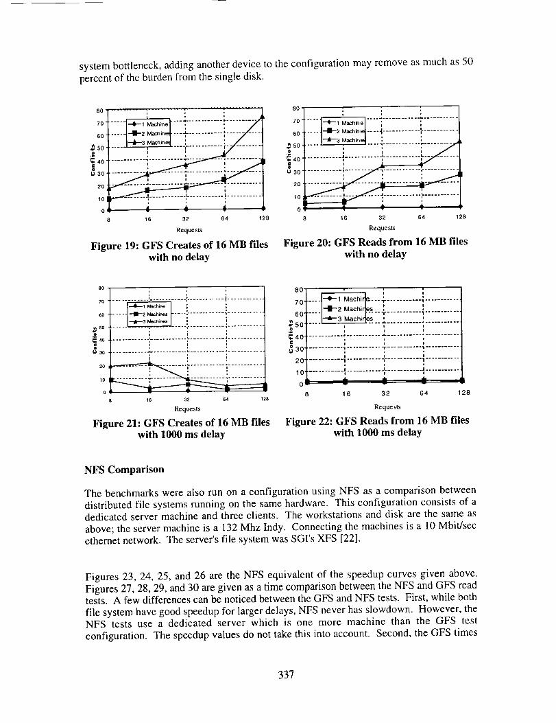
systembottleneck,addinganotherdeviceto theconfigurationmayremoveasmuchas50percentof theburdenfrom thesingledisk.
80, :......... ...........t I , , --/7o ....1-*-' ........... .....
_oi....-i--_2M,,_---,-:-...........,....y .....
sol i i-/ .......40 , i
U 30 ,
2O
10 _"_ .... ...t...........
0 _ • • '
16 32 64 128
Requests
Figure 19: GFS Creates of 16 MB fileswith no delay
80
70 .....I-+-iM_hj.oI ;-........................
_o ..... t--**-2M,_[ .... -t............ :-...........
so l'-J--3Mach_l : :......
. , ................ _........... J ............ k. ..........
==40 ! i i
_o "
10 ........... _ ...........|
o T _ _.8 16 32 64 128
Requests
Figure 20: GFS Reads from 16 MB files
with no delay
90
70 ........... ............ ............ I ..........
eo -- --(-B-2 _h_. "---:- ........... ; ..........l--J--3 Mach,_.,
50 -- --" ," 1
; ; ,40 ........... '............ '............ J ..........
=_ l i iGI
lo
o
16 32 64 128
Requests
Figure 21: GFS Creates of 16 MB fileswith 1000 ms delay
80 : ; ;
70......i_ _[..l_2-+-1Machir_s .. 'Machir_" """r ........... 1,............60" "-4r-3 Machirtes ? ........... ! ............
50" , , ,, i i l
_40 ..................................................(: = , ,i i I
,'_ :_O............. ,........... -r ........... ,............
___'_.............1 ............ ,............ 1 ............
"_,v" , , ,l 'J" J- Jm ,
8 16 32 64 128
Requests
Figure 22: GFS Reads from 16 MB fileswith 1000 ms delay
NFS Comparison
The benchmarks were also run on a configuration using NFS as a comparison between
distributed file systems running on the same hardware. This configuration consists of adedicated server machine and three clients. The workstations and disk are the same as
above; the server machine is a 132 Mhz Indy. Connecting the machines is a 10 Mbit/sec
ethernet network. The server's file system was SGI's XFS [22].
Figures 23, 24, 25, and 26 are the NFS equivalent of the speedup curves given above.
Figures 27, 28, 29, and 30 are given as a time comparison between the NFS and GFS readtests. A few differences can be noticed between the GFS and NFS tests. First, while both
file system have good speedup for larger delays, NFS never has slowdown. However, theNFS tests use a dedicated server which is one more machine than the GFS test
configuration. The speedup values do not take this into account. Second, the GFS times
337

are much smaller - between two and ten times faster. In cases where the request sizeswere large, GFS exceeded transfer speeds of 2 MB/sec.
314-Do_yoooq :
_._?....... [-a-o._, o,oq........ i............................../ [--,_o.lay osoq :/ I_Dolay 100(I :2 ................. i-........ _ .............
1.5
I
0.5 .......................... • ...........................
0 I
2
Machines
Figure 23: NFS Speedup for 1 MB filesCreated by 128 KB requests
2.5
2
t
1
0.5
0
........I+==I........:....................--41,-- Delay 050
........ "_1 -n-e-ia-Y-_1-0-0-1 ........ i ......
:iiiiii I2 3
Machines
Figure 24- NFS Speedup for 1 MB files
Read by 128 KB requests
2.5-
2-
1.5 -
1
o.5,
o
--4k- Delay 000
....... --J--Delay 0101 ....... ,,-- ....................... "_:1
I-a--D.lay osot : /"
1
I
2
Machines
Figure 25: NFS Speedup for 16 MB files
Created by I MB requests
-.4-- Delay 000 1 J
2.5 ...... --B--Delay 010(J ....... i ..................
4...... I--'-D'la' '004....... !..... --__-- -_---- ......
0,5
01 i1 2
Machines
Figure 26: NFS Speedup for 16 MB files
Read by 1 MB requests
338

300
25O
2O0
3150
lOO
50
0
Figure 27: NFS Creates of 16with no delay
I--i...........i..........._I _ch_e
A .,(L_ ''''_
........... i ........... d,,-- -. ,_ ..........
, ; ',
16 32 64 128
Requests
MB files
6OO
5OO
4O0
3
300
2OO
100
1
-m--l_, I ' ' / IL-_1_2:: Lt_ ]........... ::/ J
................. ! ! i"_........... ; ............ "...........
i
16 32 64 128
Requests
Figure 28: NFS Creates of 16 MB fileswith 1000 ms delay
120
lOO
8o
• 60
.!1--
40
20
0
JILA./r .
............ ; ............ ; ........... ; ............
,b. ......... _- -,_- _ ---,.--:, ; ;
8 16 32 64 128
Requests
Figure 29: NFS Reads from 16 MB fileswith no delay
500
450
400
350
300
2502O0
150
100
5O
0
,! ,---i...........! -/1.................:i ::::::::::::::::::::::::
I
... I
_3 Mac h_es
.... --_m--1Machme
.... l--_1 Mach_e " 3
16 32 64 128
Requests
Figure 30: NFS Reads from 16 MB fileswith 1000 ms delay
Future Work
The GFS project is still in its early phase. When Fibre Channel hardware and devicedrivers become available, an expanded set of performance tests will be performed. These
tests will be performed on file systems with different configurations - file system block
sizes, resource group layouts, etc.
The device lock mechanisms are to be studied to accommodate failure recovery. The
polling rates between locking retry requests must be tuned to provide a good compromisebetween low latencies to each node and high system throughput. Associated with these
rates is the delay between retry algorithm - constant delay versus variable delay.
The time that a node waits before resetting a device lock owned by another node must
also be investigated. This time duration has to accommodate failures in a short period
339

without resettingprematurely. Prematureresetscausethe previousowner to rebid forlocks it onceowned. This isacceptableoccasionallybut shouldbekept to aminimum.
Currently GFS storesdata in a linear layout acrossthe storagedevices. This layoutallows various forms of striping and datapartitioning, but we plan to generalizethislayout to a subpool architecture. Each subpool will have attributes reflected by itsunderlyinghardwareandconfiguration. A translationlayer will beplacedbetweenthefile system and device drivers. This translation layer will convert the linear blockaddressesfrom thefile systemto theproperdevicesandblocknumberspaddingrequestswhenappropriate.
Work hasbegun to study the cachingalgorithmsand cacheconfigurationsof storagedevices. Usinghardwareandsimulations,we areattemptingto determinethe benefitoflargecaches.Replacementpoliciesarealsobeingstudied.
Conclusion
The GFS approachto a distributed file systemusing sharedstoragedevices seemspromising given the high bandwidth natures of new networks and the increasingsophistication of devices. The architectureplaces more responsibilitieson storagedevicesthan message-basedarchitectures. Modem devicesareableto cache,performmutualexclusion,andschedulerequestsfreeingtheseburdensfrom thenodemachines.
Theresultsfrom thepreliminaryperformancemeasurementsindicatethat with sufficientdelaybetweenI/O requeststo a shareddevice,deviceparallelismis exploitedwithin thesystem. This delay may take the form of machinesperforming file system requestsbetweenlengthycomputationor low activity. Striping the file systemacrossmultipledevicesmayhaveaneffect similar to increasingthedelaybetweenrequests.
We believethat by using 100MB/sec Fibre Channeland multiple storagedevices,thissharedstorageschemewill scalewell to severalmachinesevenwith large workloads.Furthermore,the fine grain mutualexclusion implementedusingthe device locks willdecreaseconflicts to furtherincreasetheperformanceof each node and the system.
Acknowledgments
We thank Ben Gribstad at the University of Minnesota for his help with device driver
development and performance evaluations. He contributed a lot to the preliminary results
portion of this paper. We also thank Aaron Sawdey from the University of Minnesota forhis advice and experience while building the parallel SCSI test configuration used during
development and preliminary tests.
34O

The SCSI Device Locks representinput from a numberof individuals. Much of thedesignand definition is a result of dialogueswith Ciprico and Seagate. We thankRaymondGilson,StevenHansen,andEdwardSoltisof Ciprico,andJimCoomes,GeraldHoulder,andMichaelMiller of Seagate.Finally, we thankCarl Rigg andBradEackeratSilicon Graphics for granting accessto their device driver code which aided in thedevelopmentof GFS.
References
[1] P. Valduriez, "Parallel Database Systems: the case for shared--something,"Proceedings of the Ninth International Conference on Data Engineering, pp. 460-
465, 1993.
[2] G. F. Pfister, In Search of Clusters. Upper Saddle River, NJ 07458: Prentice-Hall,Inc., 1995.
[31 R. Sandberg, D. Goldberg, S. Kleiman, D. Walsh, and B. Lyon, "Design and
Implementation of the Sun Network File System", Proceedings of the Summer
USENIX Conference, pp. 119-130, 1985.
[4] J. Ousterhout, A. Cherenson, F. Douglis, M. Nelson, and B. Welch, "The Sprite
Network Operating System", IEEE Computer, pp. 23-25, February 1988.
[5] M. Satyanarayanan, "Scalable, Secure, and Highly Available Distributed File
Access", 1EEE Computer, pp. 9-20, May 1990.
[61 M. Satyanarayanan, "Coda: A Highly Available File System for a Distributed
Workstation Environment", Proceedings of the Second IEEE Workshop on
Workstation Operating Systems, September, 1989.
[7] T. Anderson, M. Dahlin, J. Neefe, D. Patterson, D. Roselli, and R. Wang, "ServerlessNetwork File System", ACM Operating System Review, vol. 29, no. 5, December1995.
[8] J. Hartman and H. Ousterhout, "Zebra: A striped network file system," USENIX
Workshop on File Systems, May 1992.
[91 M. Dahlin, C. Mather, R. Wang, T. Anderson, and D. Patterson, "A QuantitativeAnalysis of Cache Policies for Scalable Network File Systems", Proceedings of the
1994 SIGMETRICS Conference, May 1994.
[10] Digital Technical Journal, VAXcluster Systems, September 1987. Special Issue -Number 5.
[I 1] K. Matthews, "Implementing a Shared File System on a HIPPI Disk Array",
Fourteenth IEEE Symposium on Mass Storage Systems, pp. 77-88, 1995.
341

[12] R. Katz, G. Gibson, and D. Patterson, "Disk System Architectures for High
Performance Computing", Proceedings of the IEEE, vol. 77, pp. 1842-1858, 1989.
[13] C. Jurgens, "Fibre Channel: A connection to the future", IEEE Computer, pp. 82-90,
August 1995.
[14] ANSI, FC-AL Direct Attach Disk Profile (Private Loop), June 1995. Version !.8.
[15] Silicon Graphics Inc., Mountain View, CA 94029, Programming on Silicon
Graphics Systems: An Overview, 1996. Document Number 007-2476-002.
[16] Silicon Graphics Inc., Mountain View, CA 94029, IRIX Device DriverProgramming Guide, 1996. Document Number 007-0911-060.
[17] U. Vahalia, Unix Internals: The New Frontiers. Upper Saddle River, NJ07458: Prentice-Hall, Inc., 1996.
[18] M. Bach, The Design of the Unix Operating System, Englewood Cliffs, NJ07632: Prentice-Hall, Inc., 1986.
[19] B. Goodheart and J. Cox, The Magic Garden Explained, EnglewoodCliffs,NJ 07632: Prentice-Hall, Inc., 1994.
[20] P. Woodward, "Interactive Scientific Visualization of Fluid Flow", IEEE
Computer, pp. 13-25, October 1993.
[21] A. L. Reddy and J. C. Wyllie, "I/O Issues in a Multimedia System",IEEE Computer, pp. 69-74, March 1994.
[22] Silicon Graphics Inc., Mountain View, CA 94029, IRIX Admin: Disks andFilesystems, 1996. Document Number 007-2825-001.
342