Embed Size (px)
Citation preview
The Global Cable Solutions CompanyThe Global Cable Solutions Company
� Highly Flexible
� 100% EMI Emission Containment
� Designed for Longer Service Life
VFD Cables
� Shortest Lead Times• Standard 8 - 10 weeks• Emergency 2 - 4 weeks
� Best On-Time Delivery Rate
(99% average for the last 36 months)**Visit www.AmerCable.com for today’s on time delivery rate
� Highly Flexible
� Four Constructionsto Best Match YourApplication
IInnddeexx
AmerCable believes the information presented throughout this catalog to be reliable and current. All information is subject to change without notice. The information listedis approximate, and is presented only as a guide for product selection. We make no claims or warranties for the suitability of any product for any particular application.
Gexol® is a registered trademark of AmerCable Incorporated. Registered in the U.S. Patent and Trademark Office. © 2008 AmerCable Incorporated
Standard Type VFD Power Cable . . . . 2 - 3
Low Smoke Halogen-FreeType VFD Power Cable . . . . . . . . . . . 4 - 5
CIR® Type VFD Power Cable . . . . . . . . 6 - 7
Type MMV-VFD Power Cable. . . . . . . 8 - 10
Cable Assemblies . . . . . . . . . . . . . . . . 11
VFD Cable Selection Guide . . . . . . 12 - 13
VFDCABLESVFD
CABLES
www.AmerCable.com
The Global Cable Solutions Company
1www. amercable.com • e-mail: [email protected]
VFD Cables
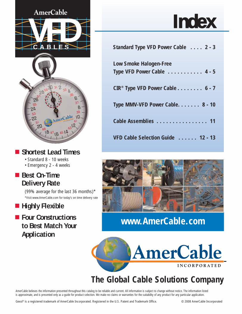
AmerCable VFD Cables are specially engineered to provide 100% containment of EMI emissionsand provide longer cable life in VFD applications.
AmerCable VFD cables feature symmetrical insulated ground conductors that reduce inducedvoltage imbalances and carry common modenoise back to the drive.
AmerCable’s high strand count conductors andbraid shield design is much more flexible, easier to install and more resistant to vibration than Type MC cable.
HHaawwkkeeGGllaanndd TTyyppeess UUnnaarrmmoorreedd AArrmmoorreedd && SShheeaatthheedd
Industrial & Safe Area (IP68) 121 153-XIncreased Safety 501/421 501/453/U“EExe”Explosion Proof 710 753
Class I, Div. 2 Class I, Div. 1Class I, Zone 2 Class I, Zone 1 & 2
Flameproof 501/421 501/453/U“EExd” Zone 1 & 2 (2 liter or < enclosures)
ICG 653/U(2 liter or > enclosures)
Zone 1 & 2
Hawke Gland Types
Manufactured by AmerCable Incorporated • 800-506-9473 • 713-896-5800 • Fax: 713-849-9009
37-102VFD
Standard Type VFD Power CableGexol® InsulatedThree Conductor • 2kV • Rated 110°C
2
VFD Cables
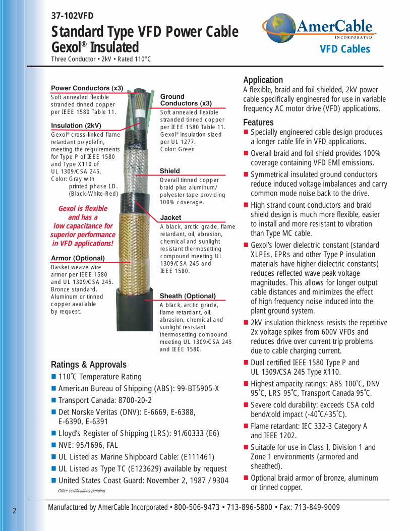
ApplicationA flexible, braid and foil shielded, 2kV powercable specifically engineered for use in variablefrequency AC motor drive (VFD) applications.
Features� Specially engineered cable design produces
a longer cable life in VFD applications.� Overall braid and foil shield provides 100%
coverage containing VFD EMI emissions.� Symmetrical insulated ground conductors
reduce induced voltage imbalances and carrycommon mode noise back to the drive.
� High strand count conductors and braid shield design is much more flexible, easier to install and more resistant to vibration than Type MC cable.
� Gexol’s lower dielectric constant (standardXLPEs, EPRs and other Type P insulationmaterials have higher dielectric constants)reduces reflected wave peak voltage magnitudes. This allows for longer output cable distances and minimizes the effect of high frequency noise induced into the plant ground system.
� 2kV insulation thickness resists the repetitive2x voltage spikes from 600V VFDs andreduces drive over current trip problems due to cable charging current.
� Dual certified IEEE 1580 Type P and UL 1309/CSA 245 Type X110.
� Highest ampacity ratings: ABS 100˚C, DNV95˚C, LRS 95˚C, Transport Canada 95˚C.
� Severe cold durability: exceeds CSA coldbend/cold impact (-40˚C/-35˚C).
� Flame retardant: IEC 332-3 Category A and IEEE 1202.
� Suitable for use in Class I, Division 1 andZone 1 environments (armored andsheathed).
� Optional braid armor of bronze, aluminum or tinned copper.
Insulation (2kV)Gexol® cross-linked flameretardant polyolefin, meeting the requirements for Type P of IEEE 1580 and Type X110 of UL 1309/CSA 245. Color: Gray with
printed phase I.D.(Black-White-Red)
JacketA black, arctic grade, flameretardant, oil, abrasion,chemical and sunlight resistant thermosetting compound meeting UL1309/CSA 245 and IEEE 1580.
Power Conductors (x3)Soft annealed flexiblestranded tinned copperper IEEE 1580 Table 11.
Ground Conductors (x3)Soft annealed flexible stranded tinned copper per IEEE 1580 Table 11.Gexol® insulation sized per UL 1277.Color: Green
Armor (Optional)Basket weave wirearmor per IEEE 1580and UL 1309/CSA 245.Bronze standard.Aluminum or tinned copper available by request.
ShieldOverall tinned copperbraid plus aluminum/polyester tape providing100% coverage.
Sheath (Optional)A black, arctic grade, flame retardant, oil, abrasion, chemical and sunlight resistant thermosetting compound meeting UL 1309/CSA 245 and IEEE 1580.
Ratings & Approvals� 110˚C Temperature Rating� American Bureau of Shipping (ABS): 99-BT5905-X� Transport Canada: 8700-20-2� Det Norske Veritas (DNV): E-6669, E-6388,
E-6390, E-6391� Lloyd’s Register of Shipping (LRS): 91/60333 (E6)� NVE: 95/1696, FAL� UL Listed as Marine Shipboard Cable: (E111461)� UL Listed as Type TC (E123629) available by request� United States Coast Guard: November 2, 1987 / 9304
Other certifications pending
Gexol is flexibleand has a
low capacitance forsuperior performance in VFD applications!
3www. amercable.com • e-mail: [email protected]
Standard Type VFD Power CableGexol® Insulated VFD Cables
GEXOL® is a registered trademark of AmerCable Incorporated
andhas a
low capacitance for superior performance in
VFD applications!
Gexolis
flexible
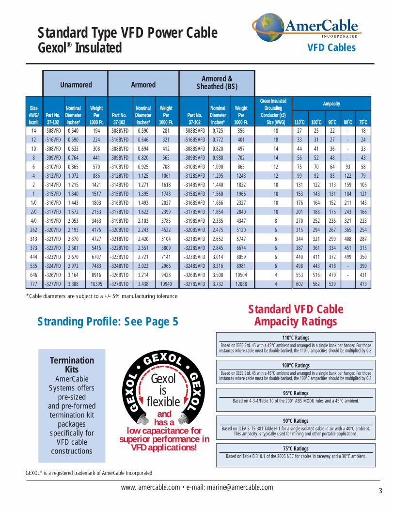
110°C Ratings Based on IEEE Std. 45 with a 45°C ambient and arranged in a single bank per hanger. For those
instances where cable must be double banked, the 110°C ampacities should be multiplied by 0.8.
100°C Ratings Based on IEEE Std. 45 with a 45°C ambient and arranged in a single bank per hanger. For those
instances where cable must be double banked, the 100°C ampacities should be multiplied by 0.8.
95°C Ratings Based on 4-3-4/Table 10 of the 2001 ABS MODU rules and a 45°C ambient.
90°C Ratings Based on ICEA S-75-381 Table H-1 for a single isolated cable in air with a 40°C ambient.
This ampacity is typically used for mining and other portable applications.
75°C Ratings Based on Table B.310.1 of the 2005 NEC for cables in raceway and a 30°C ambient.
Standard VFD Cable Ampacity Ratings
SSiizzee NNoommiinnaall WWeeiigghhtt NNoommiinnaall WWeeiigghhtt NNoommiinnaall WWeeiigghhttAAWWGG// PPaarrtt NNoo.. DDiiaammeetteerr PPeerr PPaarrtt NNoo.. DDiiaammeetteerr PPeerr PPaarrtt NNoo.. DDiiaammeetteerr PPeerrkkccmmiill 3377--110022 IInncchheess** 11000000 FFtt.. 3377--110022 IInncchheess** 11000000 FFtt.. 3377--110022 IInncchheess** 11000000 FFtt.. SSiizzee ((AAWWGG)) 111100˚̊CC 110000˚̊CC 9955˚̊CC 9900˚̊CC 7755˚̊CC
14 -508VFD 0.540 194 -508BVFD 0.590 281 -508BSVFD 0.725 356 18 27 25 22 - 18
12 -516VFD 0.590 224 -516BVFD 0.646 321 -516BSVFD 0.772 401 18 33 31 27 - 24
10 -308VFD 0.633 308 -308BVFD 0.694 412 -308BSVFD 0.820 497 14 44 41 36 - 33
8 -309VFD 0.764 441 -309BVFD 0.820 565 -309BSVFD 0.988 702 14 56 52 48 - 43
6 -310VFD 0.865 570 -310BVFD 0.925 708 -310BSVFD 1.090 865 12 75 70 64 93 58
4 -312VFD 1.072 886 -312BVFD 1.125 1061 -312BSVFD 1.295 1243 12 99 92 85 122 79
2 -314VFD 1.215 1421 -314BVFD 1.271 1618 -314BSVFD 1.440 1822 10 131 122 113 159 105
1 -315VFD 1.340 1517 -315BVFD 1.395 1743 -315BSVFD 1.560 1966 10 153 143 131 184 121
1/0 -316VFD 1.443 1803 -316BVFD 1.493 2027 -316BSVFD 1.666 2327 10 176 164 152 211 145
2/0 -317VFD 1.572 2153 -317BVFD 1.622 2399 -317BSVFD 1.854 2840 10 201 188 175 243 166
4/0 -319VFD 2.053 3463 -319BVFD 2.103 3785 -319BSVFD 2.335 4347 8 270 252 235 321 223
262 -320VFD 2.193 4175 -320BVFD 2.243 4522 -320BSVFD 2.475 5120 6 315 294 267 365 254
313 -321VFD 2.370 4727 -321BVFD 2.420 5104 -321BSVFD 2.652 5747 6 344 321 299 408 287
373 -322VFD 2.501 5415 -322BVFD 2.551 5809 -322BSVFD 2.845 6674 6 387 361 334 451 315
444 -323VFD 2.670 6707 -323BVFD 2.721 7141 -323BSVFD 3.014 8059 6 440 411 372 499 350
535 -324VFD 2.972 7483 -324BVFD 3.022 2966 -324BSVFD 3.316 8981 6 498 443 418 - 390
646 -326VFD 3.164 8916 -326BVFD 3.214 9428 -326BSVFD 3.508 10504 4 553 516 470 - 431
777 -327VFD 3.388 10395 -327BVFD 3.438 10940 -327BSVFD 3.732 12088 4 602 562 529 473
*Cable diameters are subject to a +/- 5% manufacturing tolerance
GGrreeeenn IInnssuullaatteeddGGrroouunnddiinngg
CCoonndduuccttoorr ((xx33))
Unarmored ArmoredArmored &
Sheathed (BS)
AAmmppaacciittyy
Stranding Profile: See Page 5
Termination Kits
AmerCableSystems offers
pre-sized and pre-formed termination kit
packages specifically for
VFD cable constructions
Manufactured by AmerCable Incorporated • 800-506-9473 • 713-896-5800 • Fax: 713-849-9009
37-103VFD
Low Smoke Halogen-FreeType VFD CableThree Conductor • 2kV • Rated 110°C • Gexol®-HF Insulation
4
VFD Cables
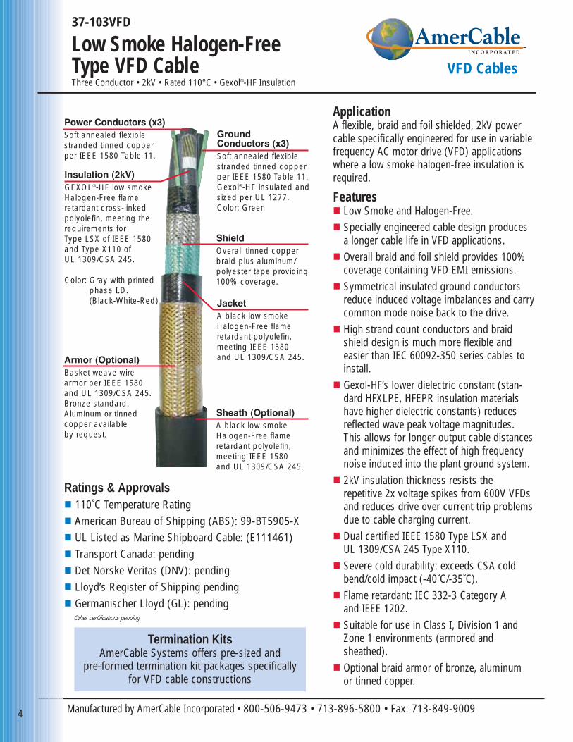
ApplicationA flexible, braid and foil shielded, 2kV powercable specifically engineered for use in variablefrequency AC motor drive (VFD) applicationswhere a low smoke halogen-free insulation isrequired.
Features� Low Smoke and Halogen-Free.� Specially engineered cable design produces
a longer cable life in VFD applications.� Overall braid and foil shield provides 100%
coverage containing VFD EMI emissions.� Symmetrical insulated ground conductors
reduce induced voltage imbalances and carrycommon mode noise back to the drive.
� High strand count conductors and braid shield design is much more flexible and easier than IEC 60092-350 series cables toinstall.
� Gexol-HF’s lower dielectric constant (stan-dard HFXLPE, HFEPR insulation materialshave higher dielectric constants) reducesreflected wave peak voltage magnitudes.This allows for longer output cable distancesand minimizes the effect of high frequencynoise induced into the plant ground system.
� 2kV insulation thickness resists the repetitive 2x voltage spikes from 600V VFDsand reduces drive over current trip problems due to cable charging current.
� Dual certified IEEE 1580 Type LSX and UL 1309/CSA 245 Type X110.
� Severe cold durability: exceeds CSA coldbend/cold impact (-40˚C/-35˚C).
� Flame retardant: IEC 332-3 Category A and IEEE 1202.
� Suitable for use in Class I, Division 1 andZone 1 environments (armored andsheathed).
� Optional braid armor of bronze, aluminum or tinned copper.
Insulation (2kV)GEXOL®-HF low smokeHalogen-Free flame retardant cross-linkedpolyolefin, meeting therequirements for Type LSX of IEEE 1580 and Type X110 of UL 1309/CSA 245.
Color: Gray with printedphase I.D.(Black-White-Red) Jacket
A black low smoke Halogen-Free flameretardant polyolefin, meeting IEEE 1580 and UL 1309/CSA 245.
Power Conductors (x3)Soft annealed flexiblestranded tinned copperper IEEE 1580 Table 11.
Ground Conductors (x3)Soft annealed flexible stranded tinned copper per IEEE 1580 Table 11.Gexol®-HF insulated andsized per UL 1277.Color: Green
Armor (Optional)Basket weave wirearmor per IEEE 1580and UL 1309/CSA 245.Bronze standard.Aluminum or tinned copper availableby request.
ShieldOverall tinned copperbraid plus aluminum/polyester tape providing100% coverage.
Sheath (Optional)A black low smoke Halogen-Free flame retardant polyolefin, meeting IEEE 1580 and UL 1309/CSA 245.
Ratings & Approvals� 110˚C Temperature Rating� American Bureau of Shipping (ABS): 99-BT5905-X� UL Listed as Marine Shipboard Cable: (E111461)� Transport Canada: pending� Det Norske Veritas (DNV): pending� Lloyd’s Register of Shipping pending� Germanischer Lloyd (GL): pending
Other certifications pending
Termination KitsAmerCable Systems offers pre-sized and
pre-formed termination kit packages specifically for VFD cable constructions
andhas a
low capacitance for superior performance in
VFD applications!
Gexol-HFis
flexible
5www. amercable.com • e-mail: [email protected]
Low Smoke Halogen-FreeType VFD Cable VFD Cables
GEXOL® is a registered trademark of AmerCable Incorporated
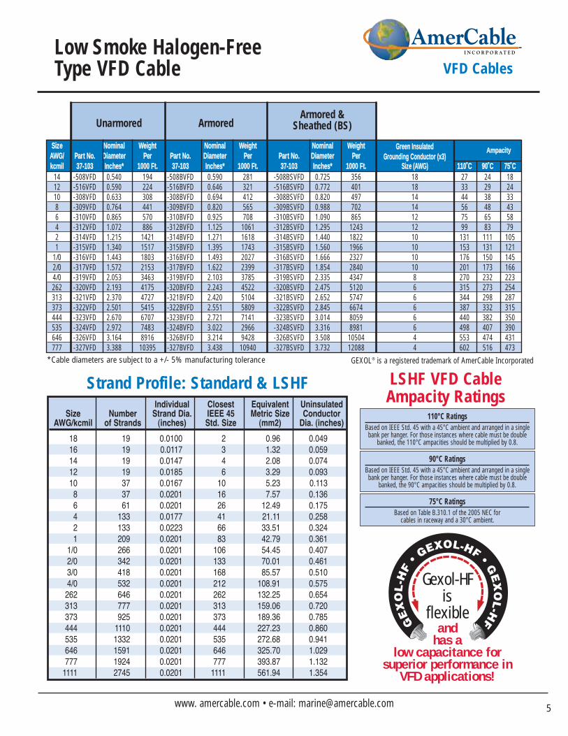
SSiizzee NNoommiinnaall WWeeiigghhtt NNoommiinnaall WWeeiigghhtt NNoommiinnaall WWeeiigghhttAAWWGG// PPaarrtt NNoo.. DDiiaammeetteerr PPeerr PPaarrtt NNoo.. DDiiaammeetteerr PPeerr PPaarrtt NNoo.. DDiiaammeetteerr PPeerrkkccmmiill 3377--110033 IInncchheess** 11000000 FFtt.. 3377--110033 IInncchheess** 11000000 FFtt.. 3377--110033 IInncchheess** 11000000 FFtt.. SSiizzee ((AAWWGG)) 111100˚̊CC 9900˚̊CC 7755˚̊CC
14 -508VFD 0.540 194 -508BVFD 0.590 281 -508BSVFD 0.725 356 18 27 24 1812 -516VFD 0.590 224 -516BVFD 0.646 321 -516BSVFD 0.772 401 18 33 29 2410 -308VFD 0.633 308 -308BVFD 0.694 412 -308BSVFD 0.820 497 14 44 38 338 -309VFD 0.764 441 -309BVFD 0.820 565 -309BSVFD 0.988 702 14 56 48 436 -310VFD 0.865 570 -310BVFD 0.925 708 -310BSVFD 1.090 865 12 75 65 584 -312VFD 1.072 886 -312BVFD 1.125 1061 -312BSVFD 1.295 1243 12 99 83 792 -314VFD 1.215 1421 -314BVFD 1.271 1618 -314BSVFD 1.440 1822 10 131 111 1051 -315VFD 1.340 1517 -315BVFD 1.395 1743 -315BSVFD 1.560 1966 10 153 131 121
1/0 -316VFD 1.443 1803 -316BVFD 1.493 2027 -316BSVFD 1.666 2327 10 176 150 1452/0 -317VFD 1.572 2153 -317BVFD 1.622 2399 -317BSVFD 1.854 2840 10 201 173 1664/0 -319VFD 2.053 3463 -319BVFD 2.103 3785 -319BSVFD 2.335 4347 8 270 232 223262 -320VFD 2.193 4175 -320BVFD 2.243 4522 -320BSVFD 2.475 5120 6 315 273 254313 -321VFD 2.370 4727 -321BVFD 2.420 5104 -321BSVFD 2.652 5747 6 344 298 287373 -322VFD 2.501 5415 -322BVFD 2.551 5809 -322BSVFD 2.845 6674 6 387 332 315444 -323VFD 2.670 6707 -323BVFD 2.721 7141 -323BSVFD 3.014 8059 6 440 382 350535 -324VFD 2.972 7483 -324BVFD 3.022 2966 -324BSVFD 3.316 8981 6 498 407 390646 -326VFD 3.164 8916 -326BVFD 3.214 9428 -326BSVFD 3.508 10504 4 553 474 431777 -327VFD 3.388 10395 -327BVFD 3.438 10940 -327BSVFD 3.732 12088 4 602 516 473
*Cable diameters are subject to a +/- 5% manufacturing tolerance
GGrreeeenn IInnssuullaatteeddGGrroouunnddiinngg CCoonndduuccttoorr ((xx33))
110°C Ratings Based on IEEE Std. 45 with a 45°C ambient and arranged in a singlebank per hanger. For those instances where cable must be double
banked, the 110°C ampacities should be multiplied by 0.8.
90°C Ratings Based on IEEE Std. 45 with a 45°C ambient and arranged in a singlebank per hanger. For those instances where cable must be double
banked, the 90°C ampacities should be multiplied by 0.8.
75°C Ratings Based on Table B.310.1 of the 2005 NEC for
cables in raceway and a 30°C ambient.
LSHF VFD Cable Ampacity Ratings
Unarmored ArmoredArmored &
Sheathed (BS)
AAmmppaacciittyy
Individual Closest Equivalent UninsulatedSize Number Strand Dia. IEEE 45 Metric Size Conductor
AWG/kcmil of Strands (inches) Std. Size (mm2) Dia. (inches)
181614121086421
1/02/03/04/0
262313373444535646777
1111
19191919373761
133133209266342418532646777925
11101332159119242745
0.0100 0.0117 0.0147 0.01850.01670.0201 0.0201 0.01770.0223 0.0201 0.0201 0.0201 0.0201 0.0201 0.0201 0.0201 0.02010.0201 0.0201 0.0201 0.0201 0.0201
2346
101626416683
106133168212262313373444535646777
1111
0.96 1.32 2.083.29 5.23 7.57
12.49 21.11 33.51 42.7954.45 70.01 85.57
108.91 132.25159.06 189.36227.23272.68325.70393.87561.94
0.0490.059 0.0740.093 0.113 0.1360.1750.2580.3240.361 0.4070.4610.510 0.5750.6540.720 0.7850.8600.9411.0291.1321.354
Strand Profile: Standard & LSHF
Manufactured by AmerCable Incorporated • 800-506-9473 • 713-896-5800 • Fax: 713-849-9009
37-102 CIRVFD
CIR® Type VFD Power CableGexol® InsulatedThree Conductor • 2kV • Rated 90°C
6
VFD Cables
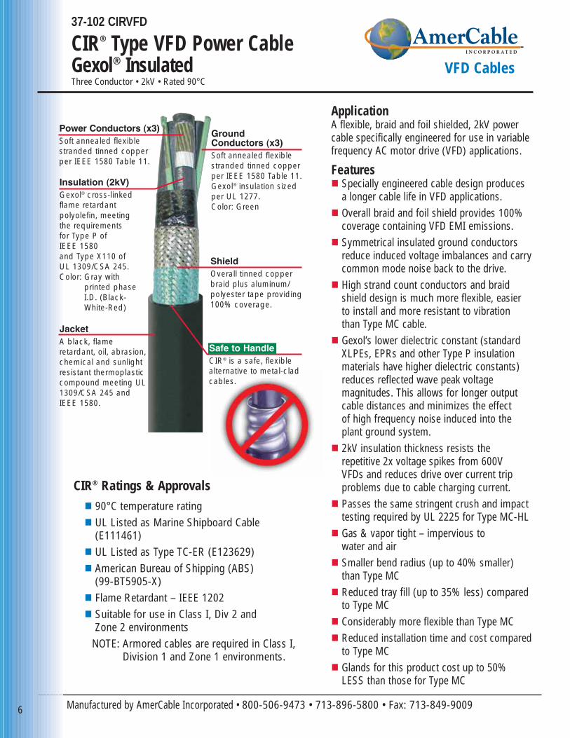
ApplicationA flexible, braid and foil shielded, 2kV powercable specifically engineered for use in variablefrequency AC motor drive (VFD) applications.
Features� Specially engineered cable design produces
a longer cable life in VFD applications.� Overall braid and foil shield provides 100%
coverage containing VFD EMI emissions.� Symmetrical insulated ground conductors
reduce induced voltage imbalances and carrycommon mode noise back to the drive.
� High strand count conductors and braid shield design is much more flexible, easier to install and more resistant to vibration than Type MC cable.
� Gexol’s lower dielectric constant (standardXLPEs, EPRs and other Type P insulationmaterials have higher dielectric constants)reduces reflected wave peak voltage magnitudes. This allows for longer output cable distances and minimizes the effect of high frequency noise induced into the plant ground system.
� 2kV insulation thickness resists the repetitive 2x voltage spikes from 600V VFDs and reduces drive over current tripproblems due to cable charging current.
� Passes the same stringent crush and impact testing required by UL 2225 for Type MC-HL
� Gas & vapor tight – impervious to water and air
� Smaller bend radius (up to 40% smaller) than Type MC
� Reduced tray fill (up to 35% less) comparedto Type MC
� Considerably more flexible than Type MC� Reduced installation time and cost compared
to Type MC� Glands for this product cost up to 50%
LESS than those for Type MC
Insulation (2kV)Gexol® cross-linked flame retardant polyolefin, meeting the requirements for Type P of IEEE 1580 and Type X110 of UL 1309/CSA 245. Color: Gray with
printed phase I.D. (Black-White-Red)
JacketA black, flame retardant, oil, abrasion,chemical and sunlightresistant thermoplasticcompound meeting UL1309/CSA 245 and IEEE 1580.
Power Conductors (x3)Soft annealed flexiblestranded tinned copperper IEEE 1580 Table 11.
Ground Conductors (x3)Soft annealed flexible stranded tinned copper per IEEE 1580 Table 11.Gexol® insulation sized per UL 1277.Color: Green
ShieldOverall tinned copperbraid plus aluminum/polyester tape providing100% coverage.
CIR® Ratings & Approvals� 90°C temperature rating� UL Listed as Marine Shipboard Cable
(E111461)� UL Listed as Type TC-ER (E123629)� American Bureau of Shipping (ABS)
(99-BT5905-X)� Flame Retardant – IEEE 1202� Suitable for use in Class I, Div 2 and
Zone 2 environmentsNOTE: Armored cables are required in Class I,
Division 1 and Zone 1 environments.
Safe to HandleCIR® is a safe, flexiblealternative to metal-cladcables.
7www. amercable.com • e-mail: [email protected]
CIR® Type VFD Power CableGexol® Insulated VFD Cables
Gexol® and CIR® are registered trademarks
of AmerCable Incorporated
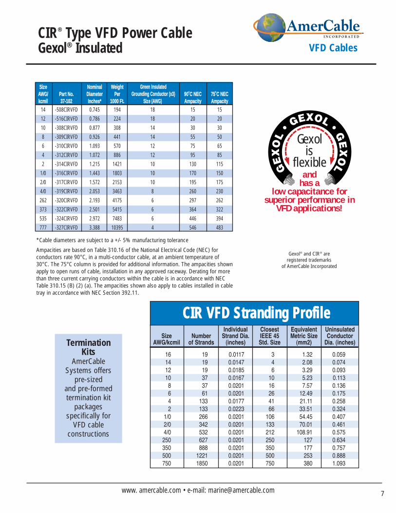
SSiizzee NNoommiinnaall WWeeiigghhttAAWWGG// PPaarrtt NNoo.. DDiiaammeetteerr PPeerr 9900˚̊CC NNEECC 7755˚̊CC NNEECCkkccmmiill 3377--110022 IInncchheess** 11000000 FFtt.. SSiizzee ((AAWWGG)) AAmmppaacciittyy AAmmppaacciittyy
14 -508CIRVFD 0.745 194 18 15 15
12 -516CIRVFD 0.786 224 18 20 20
10 -308CIRVFD 0.877 308 14 30 30
8 -309CIRVFD 0.926 441 14 55 50
6 -310CIRVFD 1.093 570 12 75 65
4 -312CIRVFD 1.072 886 12 95 85
2 -314CIRVFD 1.215 1421 10 130 115
1/0 -316CIRVFD 1.443 1803 10 170 150
2/0 -317CIRVFD 1.572 2153 10 195 175
4/0 -319CIRVFD 2.053 3463 8 260 230
262 -320CIRVFD 2.193 4175 6 297 262
373 -322CIRVFD 2.501 5415 6 364 322
535 -324CIRVFD 2.972 7483 6 446 394
777 -327CIRVFD 3.388 10395 4 546 483
GGrreeeenn IInnssuullaatteeddGGrroouunnddiinngg CCoonndduuccttoorr ((xx33))
andhas a
low capacitance for superior performance in
VFD applications!
Gexolis
flexible
Ampacities are based on Table 310.16 of the National Electrical Code (NEC) for conductors rate 90°C, in a multi-conductor cable, at an ambient temperature of30°C. The 75°C column is provided for additional information. The ampacities shownapply to open runs of cable, installation in any approved raceway. Derating for morethan three current carrying conductors within the cable is in accordance with NECTable 310.15 (B) (2) (a). The ampacities shown also apply to cables installed in cabletray in accordance with NEC Section 392.11.
*Cable diameters are subject to a +/- 5% manufacturing tolerance
Individual Closest Equivalent UninsulatedSize Number Strand Dia. IEEE 45 Metric Size Conductor
AWG/kcmil of Strands (inches) Std. Size (mm2) Dia. (inches)
161412108642
1/02/04/0
250350500750
191919373761
133133266342532627888
12211850
0.0117 0.0147 0.01850.01670.0201 0.0201 0.01770.0223 0.0201 0.0201 0.0201 0.0201 0.0201 0.0201 0.0201
346
1016264166
106133212250350500750
1.32 2.083.29 5.23 7.57
12.49 21.11 33.51 54.45 70.01
108.91 127177253380
0.059 0.0740.093 0.113 0.1360.1750.2580.3240.4070.4610.5750.6340.7570.8881.093
CCIIRR VVFFDD SSttrraannddiinngg PPrrooffiillee
Termination Kits
AmerCableSystems offers
pre-sized and pre-formed termination kit
packages specifically for
VFD cable constructions
Manufactured by AmerCable Incorporated • 800-506-9473 • 713-896-5800 • Fax: 713-849-9009
37-105VFD
Type MMV-VFDPower CableThree Conductor: 8kV –15kV • 133% Insulation Level • Rated 90°C
8
VFD Cables
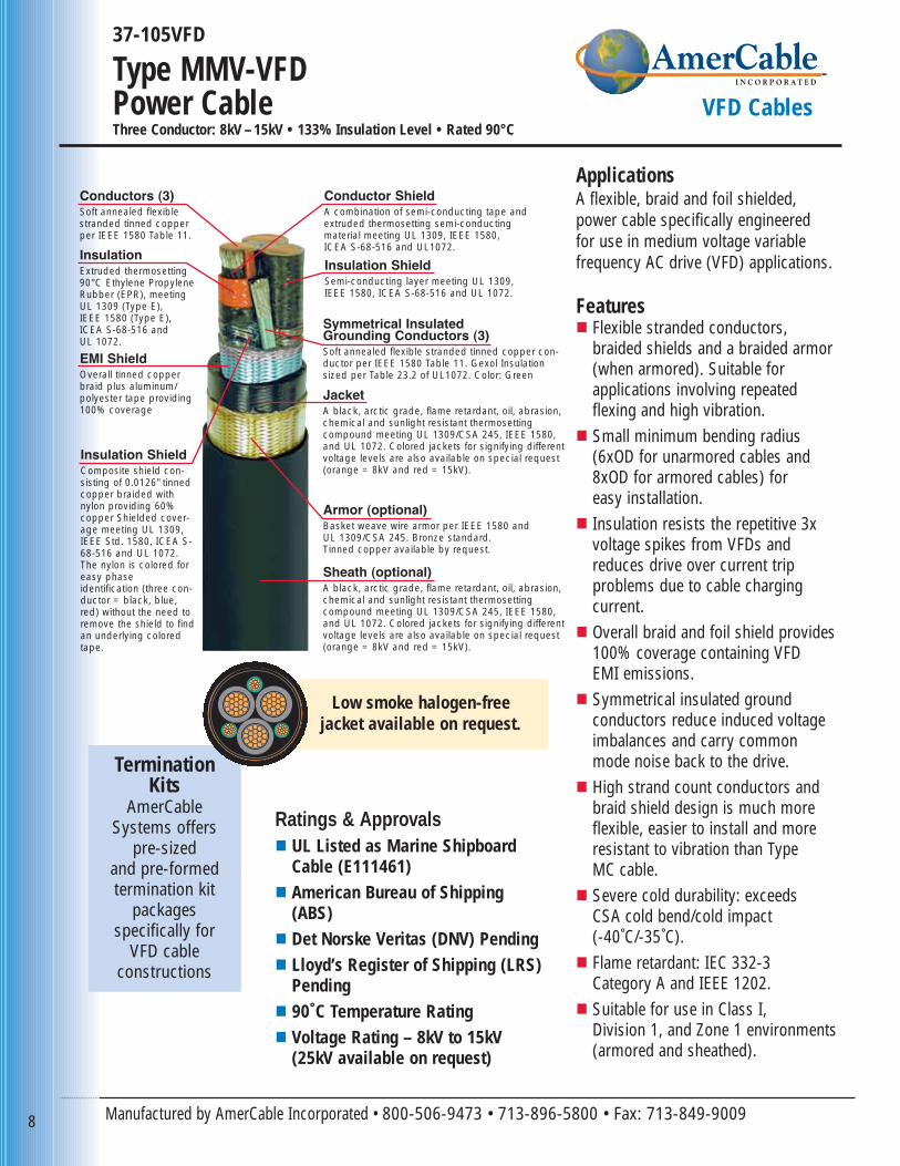
ApplicationsA flexible, braid and foil shielded,power cable specifically engineered for use in medium voltage variable frequency AC drive (VFD) applications.
Features� Flexible stranded conductors,
braided shields and a braided armor(when armored). Suitable for applications involving repeated flexing and high vibration.
� Small minimum bending radius (6xOD for unarmored cables and8xOD for armored cables) for easy installation.
� Insulation resists the repetitive 3x voltage spikes from VFDs andreduces drive over current trip problems due to cable charging current.
� Overall braid and foil shield provides100% coverage containing VFD EMI emissions.
� Symmetrical insulated ground conductors reduce induced voltageimbalances and carry common mode noise back to the drive.
� High strand count conductors andbraid shield design is much more flexible, easier to install and moreresistant to vibration than Type MC cable.
� Severe cold durability: exceeds CSA cold bend/cold impact (-40˚C/-35˚C).
� Flame retardant: IEC 332-3 Category A and IEEE 1202.
� Suitable for use in Class I, Division 1, and Zone 1 environments(armored and sheathed).
Conductor ShieldA combination of semi-conducting tape andextruded thermosetting semi-conductingmaterial meeting UL 1309, IEEE 1580, ICEA S-68-516 and UL1072.
Armor (optional)Basket weave wire armor per IEEE 1580 and UL 1309/CSA 245. Bronze standard. Tinned copper available by request.
JacketA black, arctic grade, flame retardant, oil, abrasion,chemical and sunlight resistant thermosetting compound meeting UL 1309/CSA 245, IEEE 1580,and UL 1072. Colored jackets for signifying differentvoltage levels are also available on special request(orange = 8kV and red = 15kV).
Sheath (optional)A black, arctic grade, flame retardant, oil, abrasion,chemical and sunlight resistant thermosetting compound meeting UL 1309/CSA 245, IEEE 1580,and UL 1072. Colored jackets for signifying differentvoltage levels are also available on special request(orange = 8kV and red = 15kV).
Insulation ShieldComposite shield con-sisting of 0.0126" tinnedcopper braided withnylon providing 60%copper Shielded cover-age meeting UL 1309,IEEE Std. 1580, ICEA S-68-516 and UL 1072.The nylon is colored foreasy phase identification (three con-ductor = black, blue,red) without the need toremove the shield to findan underlying coloredtape.
Insulation ShieldSemi-conducting layer meeting UL 1309, IEEE 1580, ICEA S-68-516 and UL 1072.
EMI ShieldOverall tinned copperbraid plus aluminum/polyester tape providing100% coverage
Conductors (3)Soft annealed flexiblestranded tinned copperper IEEE 1580 Table 11.
InsulationExtruded thermosetting90°C Ethylene PropyleneRubber (EPR), meetingUL 1309 (Type E), IEEE 1580 (Type E),ICEA S-68-516 and UL 1072.
Symmetrical InsulatedGrounding Conductors (3)Soft annealed flexible stranded tinned copper con-ductor per IEEE 1580 Table 11. Gexol Insulationsized per Table 23.2 of UL1072. Color: Green
Ratings & Approvals� UL Listed as Marine Shipboard
Cable (E111461)� American Bureau of Shipping
(ABS)� Det Norske Veritas (DNV) Pending� Lloyd’s Register of Shipping (LRS)
Pending� 90˚C Temperature Rating� Voltage Rating – 8kV to 15kV
(25kV available on request)
Termination Kits
AmerCableSystems offers
pre-sized and pre-formed termination kit
packages specifically for
VFD cable constructions
Low smoke halogen-free jacket available on request.
9www. amercable.com • e-mail: [email protected]
Type MMV-VFDPower Cable VFD Cables
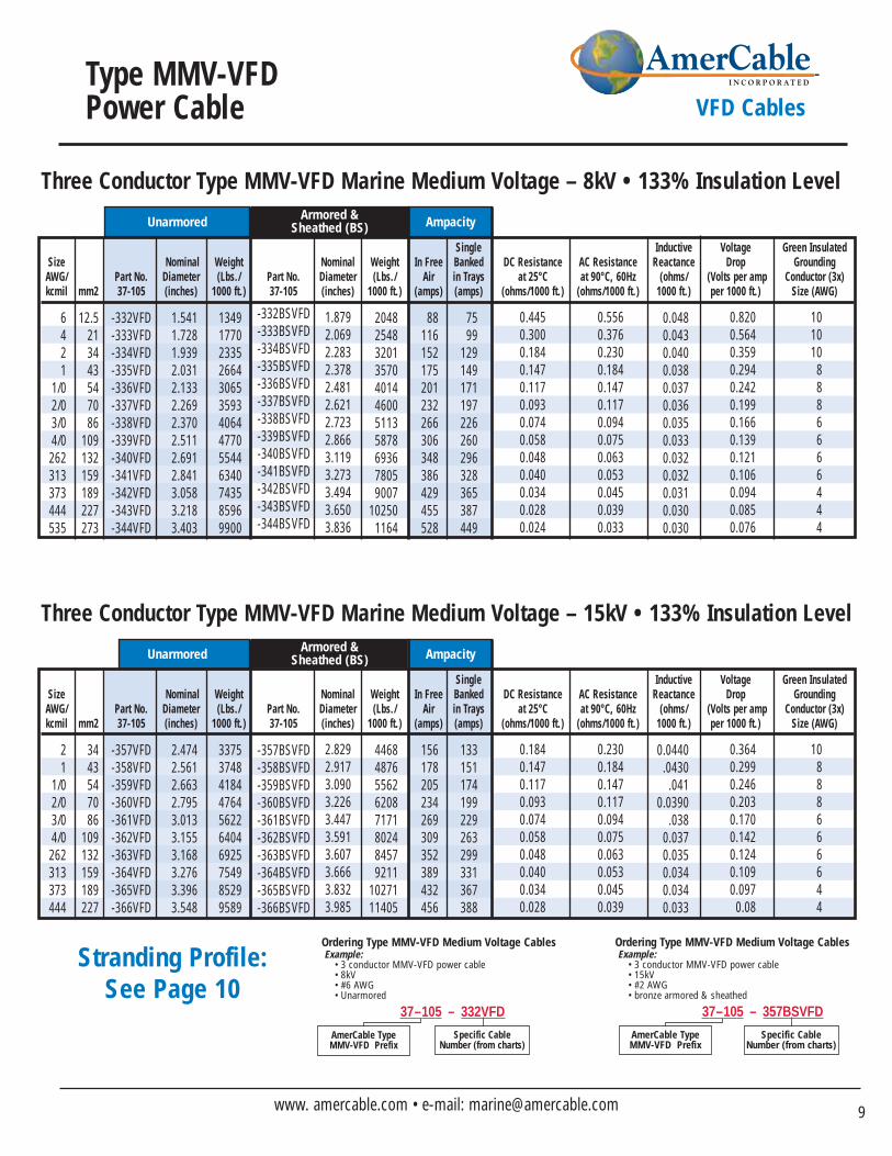
Single Inductive Voltage Green InsulatedSize Nominal Weight Nominal Weight In Free Banked DC Resistance AC Resistance Reactance Drop Grounding
AWG/ Part No. Diameter (Lbs./ Part No. Diameter (Lbs./ Air in Trays at 25°C at 90°C, 60Hz (ohms/ (Volts per amp Conductor (3x)kcmil mm2 37-105 (inches) 1000 ft.) 37-105 (inches) 1000 ft.) (amps) (amps) (ohms/1000 ft.) (ohms/1000 ft.) 1000 ft.) per 1000 ft.) Size (AWG)
6421
1/02/03/04/0262313373444535
12.5213443547086
109132159189227273
-332VFD-333VFD-334VFD-335VFD-336VFD-337VFD-338VFD-339VFD-340VFD-341VFD-342VFD-343VFD-344VFD
-332BSVFD-333BSVFD-334BSVFD-335BSVFD-336BSVFD-337BSVFD-338BSVFD-339BSVFD-340BSVFD-341BSVFD-342BSVFD-343BSVFD-344BSVFD
1.5411.7281.9392.0312.1332.2692.3702.5112.6912.8413.0583.2183.403
1349177023352664306535934064477055446340743585969900
20482548320135704014460051135878693678059007
102501164
1.8792.0692.2832.3782.4812.6212.7232.8663.1193.2733.4943.6503.836
88116152175201232266306348386429455528
7599
129149171197226260296328365387449
0.4450.3000.1840.1470.1170.0930.0740.0580.0480.0400.0340.0280.024
0.5560.3760.2300.1840.1470.1170.0940.0750.0630.0530.0450.0390.033
0.0480.0430.0400.0380.0370.0360.0350.0330.0320.0320.0310.0300.030
0.8200.5640.3590.2940.2420.1990.1660.1390.1210.1060.0940.0850.076
1010108886666444
Unarmored
Three Conductor Type MMV-VFD Marine Medium Voltage – 8kV • 133% Insulation LevelArmored &
Sheathed (BS) Ampacity
Single Inductive Voltage Green InsulatedSize Nominal Weight Nominal Weight In Free Banked DC Resistance AC Resistance Reactance Drop Grounding
AWG/ Part No. Diameter (Lbs./ Part No. Diameter (Lbs./ Air in Trays at 25°C at 90°C, 60Hz (ohms/ (Volts per amp Conductor (3x)kcmil mm2 37-105 (inches) 1000 ft.) 37-105 (inches) 1000 ft.) (amps) (amps) (ohms/1000 ft.) (ohms/1000 ft.) 1000 ft.) per 1000 ft.) Size (AWG)
21
1/02/03/04/0262313373444
3443547086
109132159189227
-357VFD-358VFD-359VFD-360VFD-361VFD-362VFD-363VFD-364VFD-365VFD-366VFD
-357BSVFD-358BSVFD-359BSVFD-360BSVFD-361BSVFD-362BSVFD-363BSVFD-364BSVFD-365BSVFD-366BSVFD
2.4742.5612.6632.7953.0133.1553.1683.2763.3963.548
3375374841844764562264046925754985299589
44684876556262087171802484579211
1027111405
2.8292.9173.0903.2263.4473.5913.6073.6663.8323.985
156178205234269309352389432456
133151174199229263299331367388
0.1840.1470.1170.0930.0740.0580.0480.0400.0340.028
0.2300.1840.1470.1170.0940.0750.0630.0530.0450.039
0.0440.0430.041
0.0390.038
0.0370.0350.0340.0340.033
0.3640.2990.2460.2030.1700.1420.1240.1090.0970.08
10888666644
Unarmored
Three Conductor Type MMV-VFD Marine Medium Voltage – 15kV • 133% Insulation LevelArmored &
Sheathed (BS) Ampacity
Ordering Type MMV-VFD Medium Voltage CablesExample:
• 3 conductor MMV-VFD power cable• 15kV• #2 AWG• bronze armored & sheathed
AmerCable Type MMV-VFD Prefix
Specific CableNumber (from charts)
37–105 – 357BSVFD
Ordering Type MMV-VFD Medium Voltage CablesExample:
• 3 conductor MMV-VFD power cable• 8kV• #6 AWG• Unarmored
AmerCable Type MMV-VFD Prefix
Specific CableNumber (from charts)
37–105 – 332VFD
Stranding Profile:See Page 10
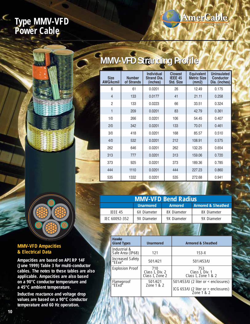
Ampacities are based on API RP 14F (June 1999) Table 3 for multi-conductorcables. The notes to these tables are alsoapplicable. Ampacities are also based on a 90°C conductor temperature and a 45°C ambient temperature.Inductive reactance and voltage drop values are based on a 90°C conductor temperature and 60 Hz operation.
MMV-VFD Ampacities & Electrical Data
MMV-VFD Stranding ProfileMMV-VFD Stranding ProfileIndividual Closest Equivalent Uninsulated
Size Number Strand Dia. IEEE 45 Metric Size ConductorAWG/kcmil of Strands (inches) Std. Size (mm2) Dia. (inches)
6
4
2
1
1/0
2/0
3/0
4/0
262
313
373
444
535
61
133
133
209
266
342
418
532
646
777
925
1110
1332
0.0201
0.0177
0.0223
0.0201
0.0201
0.0201
0.0201
0.0201
0.0201
0.0201
0.0201
0.0201
0.0201
26
41
66
83
106
133
168
212
262
313
373
444
535
12.49
21.11
33.51
42.79
54.45
70.01
85.57
108.91
132.25
159.06
189.36
227.23
272.68
0.175
0.258
0.324
0.361
0.407
0.461
0.510
0.575
0.654
0.720
0.785
0.860
0.941
HawkeGland Types Unarmored Armored & Sheathed
Industrial & Safe Area (IP68) 121 153-XIncreased Safety 501/421 501/453/U“EExe”Explosion Proof 710 753
Class I, Div. 2 Class I, Div. 1Class I, Zone 2 Class I, Zone 1 & 2
Flameproof 501/421 501/453/U (2 liter or < enclosures)“EExd” Zone 1 & 2
ICG 653/U (2 liter or > enclosures)Zone 1 & 2
MMV-VFD Bend RadiusUnarmored Armored Armored & Sheathed
IEEE 45 6X Diameter 8X Diameter 8X Diameter
IEC 60092-352 9X Diameter 9X Diameter 9X Diameter
10
Type MMV-VFDPower Cable
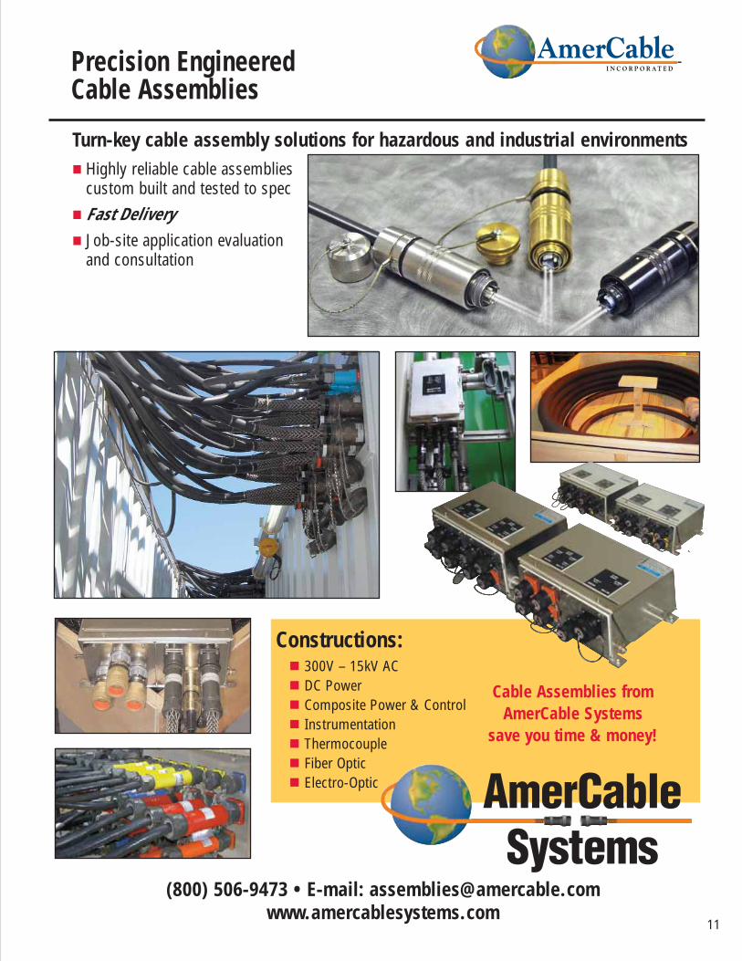
Constructions:� 300V – 15kV AC� DC Power� Composite Power & Control� Instrumentation� Thermocouple� Fiber Optic� Electro-Optic
(800) 506-9473 • E-mail: [email protected]
Cable Assemblies from AmerCable Systems
save you time & money!
Precision EngineeredCable Assemblies
Turn-key cable assembly solutions for hazardous and industrial environments� Highly reliable cable assemblies
custom built and tested to spec� Fast Delivery� Job-site application evaluation
and consultation
11
Manufactured by AmerCable Incorporated • 800-506-9473 • 713-896-5800 • Fax: 713-849-9009
Cable Selection Guide for VFD Applications
12
VFD Cables
Transformer
Shield
CT
EarthBond
InverterLine to Line Voltage – V1
MotorLine to Ground Voltage – V2
MotorGround Current – I1
EarthBond
EarthBond
Safety Earth System
l2
CC1
DiodesPower Converter
IGBT Switches
V1
V2
l1
Motor
CC2
CM
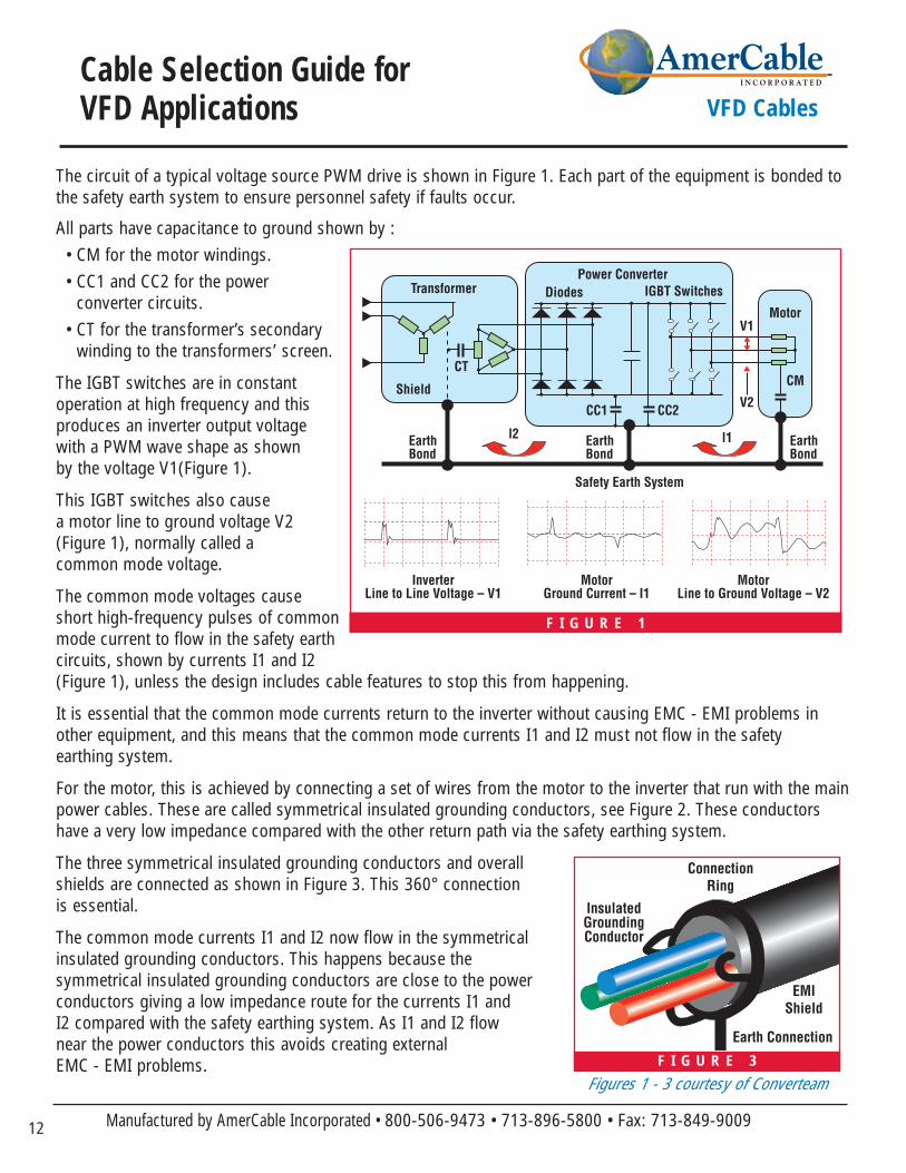
The circuit of a typical voltage source PWM drive is shown in Figure 1. Each part of the equipment is bonded tothe safety earth system to ensure personnel safety if faults occur.
All parts have capacitance to ground shown by :• CM for the motor windings.• CC1 and CC2 for the power
converter circuits.• CT for the transformer’s secondary
winding to the transformers’ screen.
The IGBT switches are in constant operation at high frequency and this produces an inverter output voltage with a PWM wave shape as shown by the voltage V1(Figure 1).
This IGBT switches also cause a motor line to ground voltage V2 (Figure 1), normally called a common mode voltage.
The common mode voltages cause short high-frequency pulses of commonmode current to flow in the safety earthcircuits, shown by currents I1 and I2 (Figure 1), unless the design includes cable features to stop this from happening.
It is essential that the common mode currents return to the inverter without causing EMC - EMI problems inother equipment, and this means that the common mode currents I1 and I2 must not flow in the safety earthing system.
For the motor, this is achieved by connecting a set of wires from the motor to the inverter that run with the mainpower cables. These are called symmetrical insulated grounding conductors, see Figure 2. These conductorshave a very low impedance compared with the other return path via the safety earthing system.
The three symmetrical insulated grounding conductors and overall shields are connected as shown in Figure 3. This 360° connection is essential.
The common mode currents I1 and I2 now flow in the symmetrical insulated grounding conductors. This happens because the symmetrical insulated grounding conductors are close to the power conductors giving a low impedance route for the currents I1 and I2 compared with the safety earthing system. As I1 and I2 flow near the power conductors this avoids creating external EMC - EMI problems. F I G U R E 3
ConnectionRing
InsulatedGroundingConductor
Earth Connection
EMIShield
F I G U R E 1
Figures 1 - 3 courtesy of Converteam
13www. amercable.com • e-mail: [email protected]
Cable Selection Guide for VFD Applications VFD Cables
Transformer
Shield
CT
EarthBond
EarthBond
EarthBond
Safety Earth System
l2 CC1
Power Converter
Motor
GroundingConductors
CC2
CM
l1
Inverter
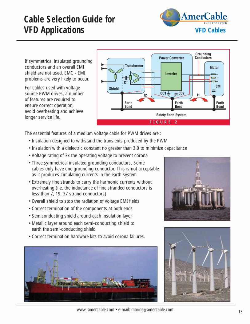
If symmetrical insulated grounding conductors and an overall EMIshield are not used, EMC - EMI problems are very likely to occur.
For cables used with voltage source PWM drives, a number of features are required to ensure correct operation, avoid overheating and achieve longer service life.
The essential features of a medium voltage cable for PWM drives are :• Insulation designed to withstand the transients produced by the PWM• Insulation with a dielectric constant no greater than 3.0 to minimize capacitance• Voltage rating of 3x the operating voltage to prevent corona• Three symmetrical insulated grounding conductors. Some
cables only have one grounding conductor. This is not acceptableas it produces circulating currents in the earth system
• Extremely fine strands to carry the harmonic currents without overheating (i.e. the inductance of fine stranded conductors is less than 7, 19, 37 strand conductors)
• Overall shield to stop the radiation of voltage EMI fields• Correct termination of the components at both ends• Semiconducting shield around each insulation layer• Metallic layer around each semi-conducting shield to
earth the semi-conducting shield• Correct termination hardware kits to avoid corona failures.
F I G U R E 2
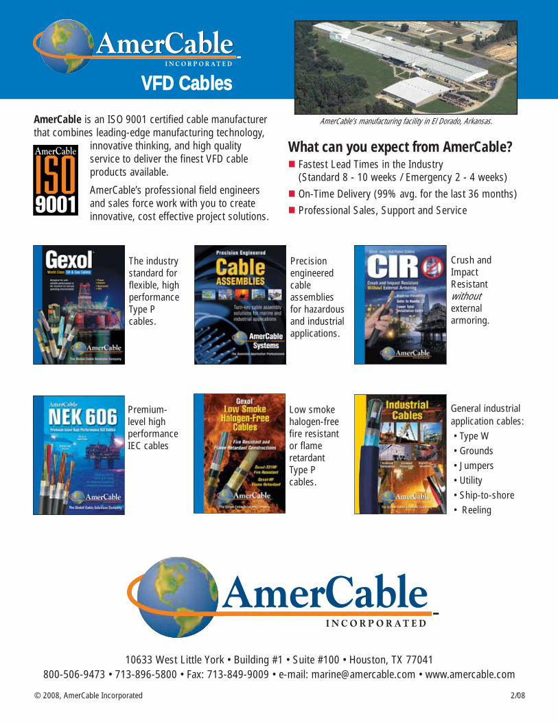
AmerCable is an ISO 9001 certified cable manufacturerthat combines leading-edge manufacturing technology,
innovative thinking, and high quality service to deliver the finest VFD cable products available.
AmerCable’s professional field engineersand sales force work with you to createinnovative, cost effective project solutions.
What can you expect from AmerCable?� Fastest Lead Times in the Industry
(Standard 8 - 10 weeks / Emergency 2 - 4 weeks)� On-Time Delivery (99% avg. for the last 36 months)� Professional Sales, Support and Service
AmerCable’s manufacturing facility in El Dorado, Arkansas.
VVFFDD CCaabblleess
2/08© 2008, AmerCable Incorporated
10633 West Little York • Building #1 • Suite #100 • Houston, TX 77041 800-506-9473 • 713-896-5800 • Fax: 713-849-9009 • e-mail: [email protected] • www.amercable.com
The industrystandard forflexible, highperformanceType P cables.
Premium-level high performanceIEC cables
Precisionengineered cable assembliesfor hazardousand industrialapplications.
Low smokehalogen-freefire resistantor flame retardant Type P cables.
Crush andImpactResistant withoutexternal armoring.
General industrialapplication cables:• Type W• Grounds• Jumpers• Utility• Ship-to-shore• Reeling