Embed Size (px)
Citation preview
Master Thesis
“ The GeoSharing project:An Openmoko geoposition sharing system ”
June 2011
This document was presented to
the Louvain School of Engineering
in Partial Fulfilment
of the Requirements
for the Degree of
MASTER IN COMPUTER ENGINEERING
Supervisor: Pr. Marc Lobelle Authors: Lamouline LaurentNuttin Vincent
Universite catholique de Louvain

“ In theory, there is no difference between theory and practice;
In practice, there is. ”
– Chuck Reid
Nous remercions chaleureusement
le Professeur Marc Lobelle, notre promoteur
ainsi que Sebastien Combefis et Xavier Carpent
pour leur guidance eclairee.

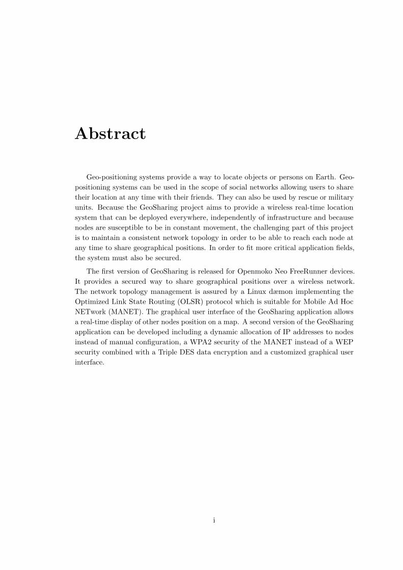
Abstract
Geo-positioning systems provide a way to locate objects or persons on Earth. Geo-
positioning systems can be used in the scope of social networks allowing users to share
their location at any time with their friends. They can also be used by rescue or military
units. Because the GeoSharing project aims to provide a wireless real-time location
system that can be deployed everywhere, independently of infrastructure and because
nodes are susceptible to be in constant movement, the challenging part of this project
is to maintain a consistent network topology in order to be able to reach each node at
any time to share geographical positions. In order to fit more critical application fields,
the system must also be secured.
The first version of GeoSharing is released for Openmoko Neo FreeRunner devices.
It provides a secured way to share geographical positions over a wireless network.
The network topology management is assured by a Linux dæmon implementing the
Optimized Link State Routing (OLSR) protocol which is suitable for Mobile Ad Hoc
NETwork (MANET). The graphical user interface of the GeoSharing application allows
a real-time display of other nodes position on a map. A second version of the GeoSharing
application can be developed including a dynamic allocation of IP addresses to nodes
instead of manual configuration, a WPA2 security of the MANET instead of a WEP
security combined with a Triple DES data encryption and a customized graphical user
interface.
i
Contents
Abstract i
Acknowledgements iv
Introduction 1
1 Openmoko Neo FreeRunner 2
1.1 Openmoko project . . . . . . . . . . . . . . . . . . . . . . . . . . . . . . 2
1.2 Specifications of the Neo FreeRunner . . . . . . . . . . . . . . . . . . . . 3
1.3 Getting started with the Neo FreeRunner . . . . . . . . . . . . . . . . . 4
1.4 Developing environment . . . . . . . . . . . . . . . . . . . . . . . . . . . 7
2 Choice of the operating system 9
2.1 Choice criteria . . . . . . . . . . . . . . . . . . . . . . . . . . . . . . . . 9
2.2 Potential choices . . . . . . . . . . . . . . . . . . . . . . . . . . . . . . . 10
2.3 Evaluation of the criteria . . . . . . . . . . . . . . . . . . . . . . . . . . 12
3 Communication with the built-in GPS module 15
3.1 GPS communication stacks . . . . . . . . . . . . . . . . . . . . . . . . . 15
3.2 Methods of geographical positions retrieval . . . . . . . . . . . . . . . . 16
3.3 Precision analysis . . . . . . . . . . . . . . . . . . . . . . . . . . . . . . . 18
4 Network infrastructures and protocols 20
4.1 Network requirements . . . . . . . . . . . . . . . . . . . . . . . . . . . . 20
4.2 Wi-Fi modes overview . . . . . . . . . . . . . . . . . . . . . . . . . . . . 21
4.3 Routing protocols overview . . . . . . . . . . . . . . . . . . . . . . . . . 25
4.4 Secured data transfer . . . . . . . . . . . . . . . . . . . . . . . . . . . . . 35
4.5 Optimized Link State Routing in GeoSharing . . . . . . . . . . . . . . . 42
ii
CONTENTS
5 Graphical User Interface 43
5.1 Graphical requirements . . . . . . . . . . . . . . . . . . . . . . . . . . . 43
5.2 Potential architecture designs . . . . . . . . . . . . . . . . . . . . . . . . 44
5.3 Choice of the architecture design . . . . . . . . . . . . . . . . . . . . . . 45
5.4 TangoGPS plugin in details . . . . . . . . . . . . . . . . . . . . . . . . . 45
6 GeoSharing project 51
6.1 OLSRd and BMF set up on the Neo FreeRunner . . . . . . . . . . . . . 51
6.2 How GeoSharing runs . . . . . . . . . . . . . . . . . . . . . . . . . . . . 53
6.3 GeoSharing core functionalities . . . . . . . . . . . . . . . . . . . . . . . 57
6.4 User manual . . . . . . . . . . . . . . . . . . . . . . . . . . . . . . . . . . 66
6.5 Limitations and further work . . . . . . . . . . . . . . . . . . . . . . . . 68
Conclusion 70
A Installation guide 72
A.1 Preliminary configurations . . . . . . . . . . . . . . . . . . . . . . . . . . 72
A.2 GeoSharing project installation . . . . . . . . . . . . . . . . . . . . . . . 77
B Licence 83
Bibliography 84
Acronyms 87
Glossary 89
Index 91
iii
Acknowledgements
During the elaboration of this project, we had the chance to integrate a lot of open-
source projects. We really want to thank people for their incredible work, motivation,
reactivity and friendliness.
We thank Erik Tromp for his help in the understanding of the documentation related
to the OLSRd BMF plugin, Martin Jansa for helping us to understand how to compile
tangoGPS on Openmoko Neo FreeRunner devices, Joshua Judson Rosen for his help in
the understanding of the GTK+ thread management involved in tangoGPS and all the
members of the mailing lists related to the SHR-project.org, olsr.org and openmoko.org.
iv
Introduction
The GeoSharing project is a system allowing users to share their geographical
position with other users. The system makes it possible for every user to see the
displacements of other users on a map. The system is deployed on Openmoko Neo
FreeRunner devices which are open smartphones running an embedded version of the
Linux operating system. Those devices are equipped with a GPS and a Wi-Fi module as
it is today the case for many modern smartphones. In order to achieve the GeoSharing
main goal which is to share geographical positions over a group of users and assuming
that every user has an Neo FreeRunner with him, the GPS module is used to get the
location of the device on Earth and the Wi-Fi module is used to spread the information
between the devices.
There are many uses for location systems. Such systems can be used to track the
positions of boyscout patrols for the organizers. But it can also have applications in
more critical fields such as military and medical rescue situations. When soldiers are in
operation, locating the different military units can indeed be crucial for tactical reasons.
From a medical standpoint, it is really important to locate the injured soldiers as quickly
as possible in order to rescue them. One can expand the application to a larger scale
such as disaster relief units that need to be dispatched in an optimal way for rescuing
victims. In these situations, it is crucial for medical units to have an effective location
system with them in order to reach the right place as fast as possible and know where
other rescue units are located.
This thesis details the analysis, design and development steps leading to a solution.
The first chapter presents the Openmoko project and the Neo FreeRunner device
specifications. The selection criteria which motivated the operating system choice is
then presented in detail in Chapter 2. Chapter 3 introduces the interactions with the
GPS module. Network protocols and the security of the application are addressed in
Chapter 4. Chapter 5 is dedicated to the graphical interface. The last chapter presents
the GeoSharing project and its limitations.
We hope you will enjoy your reading as we enjoyed to work on this project.
1
Chapter 1
Openmoko Neo FreeRunner
In the scope of this thesis, Openmoko Neo FreeRunner devices have been chosen to
be the hardware platform to support the development and the tests of the GeoSharing
application. The GeoSharing application is obviously generic and the concept can be
ported to any mobile device.
The first section of this chapter introduces the Openmoko project. The next two
sections present the Neo FreeRunner, its technical specifications and how to get started
with it. The last section presents a brief analysis of how mobile applications can be
compiled.
1.1 Openmoko project
“Openmoko is a project dedicated to delivering mobile phones with an open
source software stack. Openmoko was earlier more directly associated with
Openmoko Inc, but is nowadays a gathering of people with the shared goal of
“Free Your Phone”.”
– Offical Openmoko website: http://www.openmoko.org
Openmoko Inc. (Figure 1.1(a)) is a Taiwanese company founded in 2006 by Sean
Moss-Pultz with the help of Timothy Chen. These two people were the originators
of the Openmoko smartphone and other electronic mobile devices. Since 2010, this
company has cancelled many future projects. This is the reason why the Openmoko
project (Figure 1.1(b)) is now under the supervision of a world-wide community of
developers which proposes new hardware updates for existing open smartphones such
as the Openmoko Neo FreeRunner (also called GTA02). There exists now many local
communities (english, french, german, etc.) taking care of the project. For example,
the french speaking community was founded by Johann Suhm and his blog related to
the Openmoko project is available at http://www.openmoko-fr.org.
2
CHAPTER 1. OPENMOKO NEO FREERUNNER
(a) Openmoko Inc. (b) Openmoko.org.
Figure 1.1: (a) Openmoko Inc. is a Taiwanese company founded in 2006. (b) Openmoko.org isunder the supervision of a world-wide community.
1.2 Specifications of the Neo FreeRunner
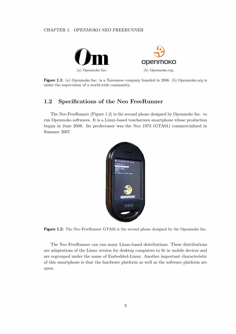
The Neo FreeRunner (Figure 1.2) is the second phone designed by Openmoko Inc. to
run Openmoko softwares. It is a Linux-based touchscreen smartphone whose production
began in June 2008. Its predecessor was the Neo 1973 (GTA01) commercialized in
Summer 2007.
Figure 1.2: The Neo FreeRunner GTA02 is the second phone designed by the Openmoko Inc.
The Neo FreeRunner can run many Linux-based distributions. These distributions
are adaptations of the Linux version for desktop computers to fit in mobile devices and
are regrouped under the name of Embedded-Linux. Another important characteristic
of this smartphone is that the hardware platform as well as the software platform are
open.
3
CHAPTER 1. OPENMOKO NEO FREERUNNER
The main specifications of the Neo FreeRunner are:
• a weight of about 184 grams
• a 400MhZ ARM processor
• 128 MB RAM memory
• 256 MB flash memory
• a micro SD card slot
• a 480x640 pixels touchscreen
• an internal GPS module
• 802.11 b/g Wi-Fi
• bluetooth
• two 3D accelerometers
• tri-band GSM and GPRS
• USB connector
Using such a device has advantages whose mains are:
1. the openness of all applications developed for it. This concept offers a large
freedom in using and modifying already existing software installed on the device;
2. the integration of many communications means such as Wi-Fi, bluetooth,
GPRS, etc.
The Openmoko FreeRunner can be bought from official FreeRunner distributors
for about 250 e. The distributors list is available on the Openmoko Inc. website:
http://www.openmoko.com.
1.3 Getting started with the Neo FreeRunner
In order to have a better idea about how to get started with the Neo FreeRunner,
this section presents a brief overview of the device itself and technical terms that are
commonly used in the smartphones’ domain. This section also explains different ways
to get an internet connection on the Neo FreeRunner.
1.3.1 Buttons and connectors
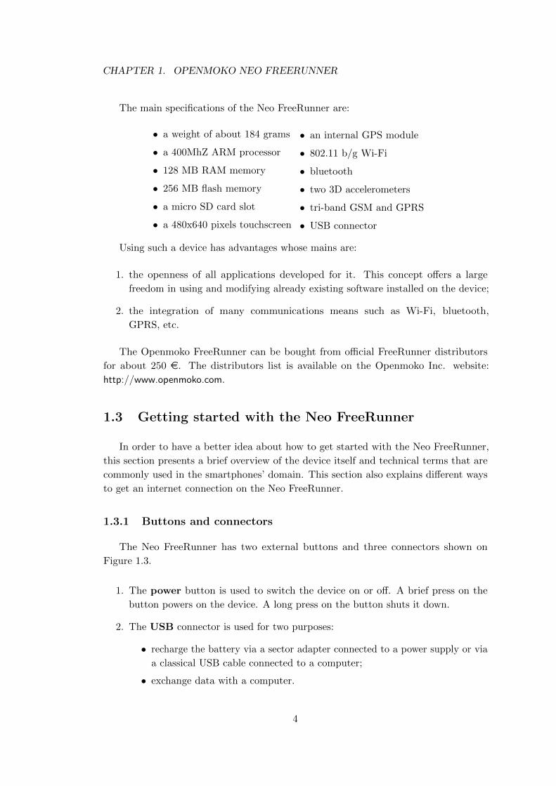
The Neo FreeRunner has two external buttons and three connectors shown on
Figure 1.3.
1. The power button is used to switch the device on or off. A brief press on the
button powers on the device. A long press on the button shuts it down.
2. The USB connector is used for two purposes:
• recharge the battery via a sector adapter connected to a power supply or via
a classical USB cable connected to a computer;
• exchange data with a computer.
4
CHAPTER 1. OPENMOKO NEO FREERUNNER
(a) Right side of the GTA02 (b) Left side of the GTA02
Figure 1.3: (a) On the right side of the GTA02, the power button, an USB connector and anexternal GPS antenna connector. (b) On the left side of the GTA02, the ‘aux’ button and a2.5mm phone jack connector. (Pictures from http://wiki.openmoko.org)
3. The external GPS antenna connector can be used to plug an external antenna
in to improve the reception quality. Due to the smallness of the Neo FreeRunner
(and its components such as the Wi-Fi and GPS antennas), the GPS accuracy
is quite limited. The reception quality is thus improved when an external GPS
antenna is plugged in.
4. The ‘aux’ button is used in combination with the power button to access the boot
menu and to browse the items of this menu.
5. The 2.5mm phone jack connector allows users to plug an headphone set in.
The actions associated to the interactions with the power and ‘aux’ buttons are
often customized and generally depends on the operating system installed on the device.
For example, the power button can be used to access the power management menu and
the ‘aux’ button is used to lock and unlock the smartphone.
1.3.2 Memories and bootloader
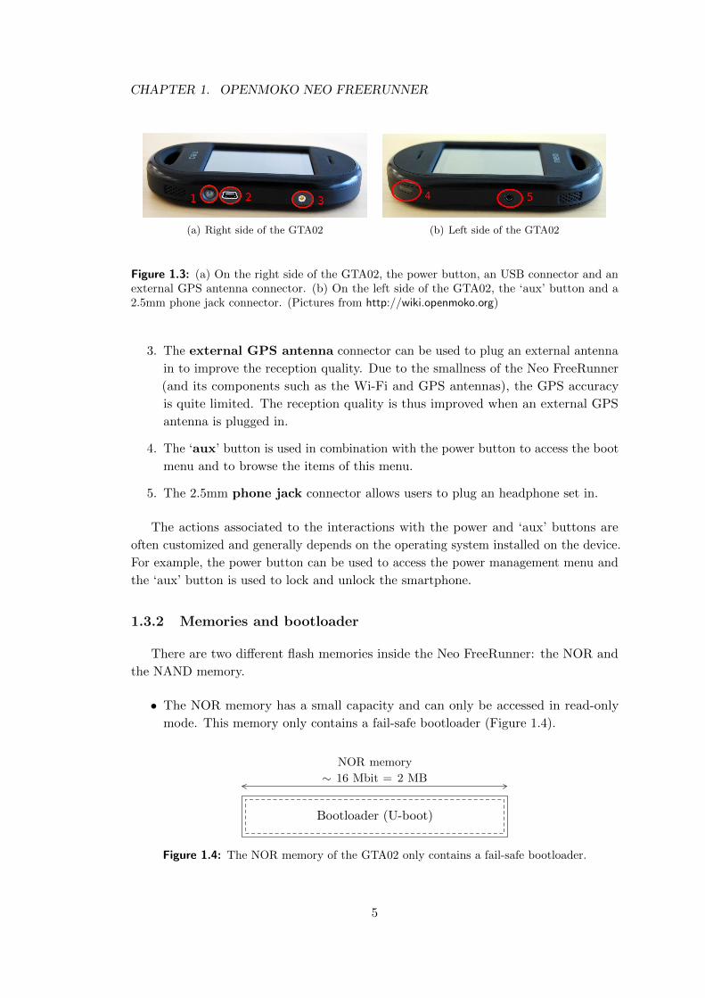
There are two different flash memories inside the Neo FreeRunner: the NOR and
the NAND memory.
• The NOR memory has a small capacity and can only be accessed in read-only
mode. This memory only contains a fail-safe bootloader (Figure 1.4).
Bootloader (U-boot)
NOR memory
∼ 16 Mbit = 2 MB
Figure 1.4: The NOR memory of the GTA02 only contains a fail-safe bootloader.
5
CHAPTER 1. OPENMOKO NEO FREERUNNER
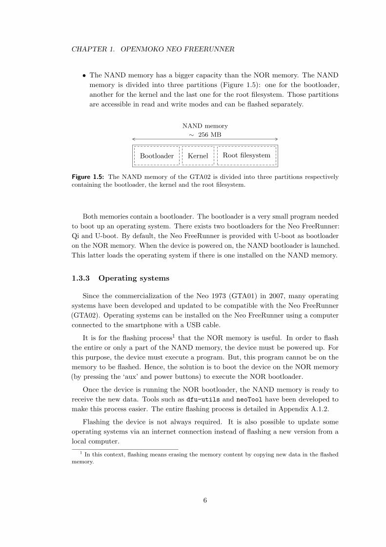
• The NAND memory has a bigger capacity than the NOR memory. The NAND
memory is divided into three partitions (Figure 1.5): one for the bootloader,
another for the kernel and the last one for the root filesystem. Those partitions
are accessible in read and write modes and can be flashed separately.
Bootloader Kernel Root filesystem
NAND memory
∼ 256 MB
Figure 1.5: The NAND memory of the GTA02 is divided into three partitions respectivelycontaining the bootloader, the kernel and the root filesystem.
Both memories contain a bootloader. The bootloader is a very small program needed
to boot up an operating system. There exists two bootloaders for the Neo FreeRunner:
Qi and U-boot. By default, the Neo FreeRunner is provided with U-boot as bootloader
on the NOR memory. When the device is powered on, the NAND bootloader is launched.
This latter loads the operating system if there is one installed on the NAND memory.
1.3.3 Operating systems
Since the commercialization of the Neo 1973 (GTA01) in 2007, many operating
systems have been developed and updated to be compatible with the Neo FreeRunner
(GTA02). Operating systems can be installed on the Neo FreeRunner using a computer
connected to the smartphone with a USB cable.
It is for the flashing process1 that the NOR memory is useful. In order to flash
the entire or only a part of the NAND memory, the device must be powered up. For
this purpose, the device must execute a program. But, this program cannot be on the
memory to be flashed. Hence, the solution is to boot the device on the NOR memory
(by pressing the ‘aux’ and power buttons) to execute the NOR bootloader.
Once the device is running the NOR bootloader, the NAND memory is ready to
receive the new data. Tools such as dfu-utils and neoTool have been developed to
make this process easier. The entire flashing process is detailed in Appendix A.1.2.
Flashing the device is not always required. It is also possible to update some
operating systems via an internet connection instead of flashing a new version from a
local computer.
1 In this context, flashing means erasing the memory content by copying new data in the flashedmemory.
6
CHAPTER 1. OPENMOKO NEO FREERUNNER
1.3.4 Internet connection
There exists four different ways to get an internet connectivity on the Neo FreeRun-
ner.
The first possibility is to use the GPRS modem of the device. When a valid SIM card
is inserted in the phone and if the Access Point Name (APN) is correctly configured2, a
GPRS connection can be established via the mobile carrier. Unfortunately, this solution
has a low bandwidth of about 40 kbit/s [GPR11].
The second solution is to use the built-in Wi-Fi module in order to connect the
smartphone to any Wi-Fi network with several possible levels of security. In this situation,
the theoretical bandwidth is defined according to the wireless network protocol: 11 Mbit/s
for the 802.11b IEEE standard and 22 Mbit/s for the 802.11g IEEE standard [IEE11].
The last two possible solutions to get an internet connectivity on the Neo FreeRunner
use a connection between the smartphone and a computer already connected to the
internet. Preliminary configurations are needed for the computer to behave as a simple
router. It must forward packets coming from the Neo FreeRunner to the internet and
the other way around. The connection between the smartphone and the computer
can be:
• a bluetooth connection. In this case, the Bluetooth Networking Encapsulation
Protocol [BNE11] must be used.
• a USB connection. The details of this configuration are given in Appendix A.1.3.
1.4 Developing environment
Since the application developed in this thesis has to be run on the Neo FreeRunner,
it is necessary to compile it for the specific architecture of those devices. There exists
two ways to compile an application for low-cost hardware devices (i.e. low CPU and
memory capabilities).
1. The first possibility is to natively compile source files on the device. This makes the
assumption that there exists a compiler for the concerned programming language
on the specific architecture. Obviously, the low capabilities of the device have an
unfavourable impact on the compilation time. The output files of the compilation
process are then certainly compliant with the architecture of the device.
2. The second possibility is to use a cross-compiler. Such a program allows to compile,
on any computer, an application targeted for a specific architecture which is not
necessarily the same as the one of the computer on which the code is compiled.
2 For example, internet.proximus.be for the Belgian mobile carrier Proximus.
7
CHAPTER 1. OPENMOKO NEO FREERUNNER
Hence, it is possible to take advantage of the computer CPU capabilities in order
to compile faster than on the mobile device.
Both methods provide the same results. During the development of this work, the
first solution has been used mainly for its easiness. The second solution requires extra
configurations indeed, while the first one is straightforward.
8
Chapter 2
Choice of the operating system
When you get a mobile device on which you have to develop a new application,
the choice of the operating system to work with is crucial. It has indeed to fit the
application needs and some software and hardware criteria. Several variants of Linux
have been ported to the Neo FreeRunner. This chapter presents the criteria which were
chosen according to their relevance for the intended application to be developed. The
choice of the operating system according to those criteria is then presented.
2.1 Choice criteria
In order to choose the most suitable operating system on which to develop and run
the application, some requirements need to be defined and satisfied. These latter are
related to the capabilities of the material and the needs of the application. For the
GeoSharing project, a lightweight operating system is more than enough. The only
features it has to support are a user interface, a GPS module and a Wi-Fi module.
This section establishes a list of four criteria that must be satisfied by the operating
system. Those criteria are to be evaluated and scored as objectively as possible on
several operating systems.
1. Stability: the most important point is the stability offered by the operating
system. This means that the system has to be reliable and robust and that
it should not crash. In this work, the stability has been evaluated thanks to
three major tests: the keyboard functionality, the native1 applications usage and
the use of the GPS and Wi-Fi modules. We will consider that the operating
system is unstable if an application is able to crash it. If the operating system
is well implemented, an application should not crash it. Such a behaviour will
immediately discard the operating system.
1 In this context, native means that the application is provided with the operating system package.
9
CHAPTER 2. CHOICE OF THE OPERATING SYSTEM
2. Maintenance: this criterion will evaluate if a system is still maintained by
developers or not. Systems that are no more developed will be discarded in order
to only keep up-to-date systems.
3. Developers usage: the fact that an operating system is widely used by developers
community can be interpreted as a sign of trust. The most used system will indeed
be susceptible to be the most satisfying one in terms of maintenance and stability.
It may also be the system with the larger community working around.
4. Energy consumption: the energy consumption is not the most critical factor
in our case but it can be interesting to use a system whose consumption is not
excessive. The operating system will be tested with the Wi-Fi and the GPS
activated without letting the system suspend in order to evaluate the longevity in
the worst-case2.
2.2 Potential choices
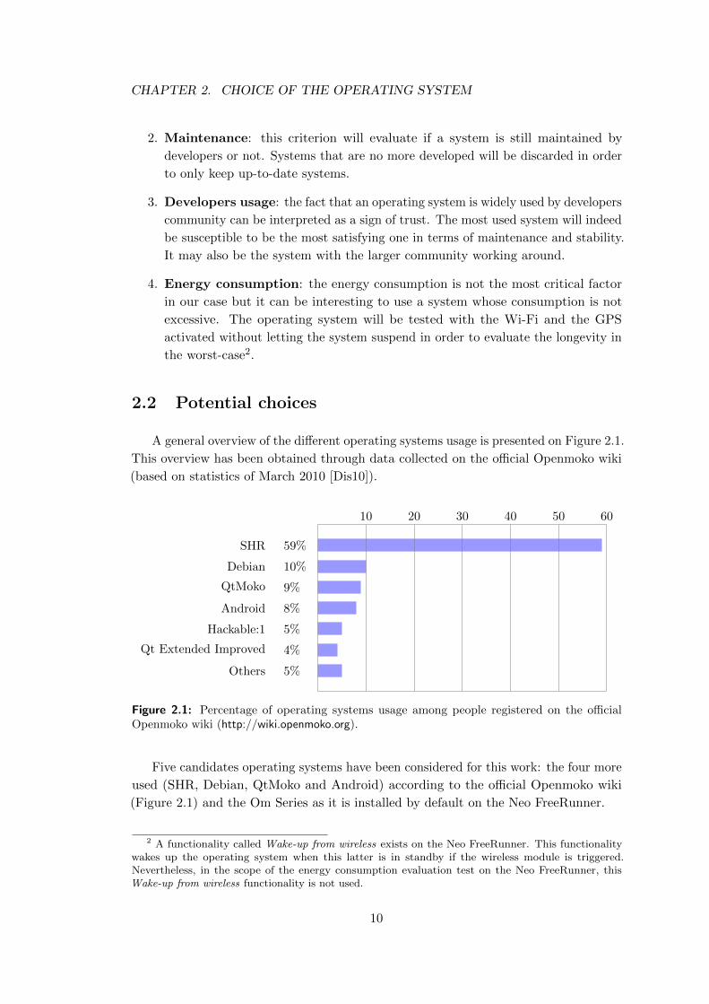
A general overview of the different operating systems usage is presented on Figure 2.1.
This overview has been obtained through data collected on the official Openmoko wiki
(based on statistics of March 2010 [Dis10]).
10 20 30 40 50 60
SHR
Debian
QtMoko
Android
Hackable:1
Qt Extended Improved
Others
59%
10%
9%
8%
5%
4%
5%
Figure 2.1: Percentage of operating systems usage among people registered on the officialOpenmoko wiki (http://wiki.openmoko.org).
Five candidates operating systems have been considered for this work: the four more
used (SHR, Debian, QtMoko and Android) according to the official Openmoko wiki
(Figure 2.1) and the Om Series as it is installed by default on the Neo FreeRunner.
2 A functionality called Wake-up from wireless exists on the Neo FreeRunner. This functionalitywakes up the operating system when this latter is in standby if the wireless module is triggered.Nevertheless, in the scope of the energy consumption evaluation test on the Neo FreeRunner, thisWake-up from wireless functionality is not used.
10
CHAPTER 2. CHOICE OF THE OPERATING SYSTEM
Here is an overview of every candidate operating system:
Stable Hybrid Release
Stable Hybrid Release (SHR) is based on Debian and provides an X server environ-
ment and Illume2 which is an enlightenment window manager module for small devices.
SHR comes with a complete user manual and moves forward to a distribution for every
day use.
Debian
Debian is a well known operating system generally used on computers. It can also be
used on the Neo FreeRunner where it gives access to the numerous softwares packaged
in the Debian repositories.
QtMoko
As well as SHR, QtMoko is a distribution based on Debian and is the most active
distribution for the moment (one new version per month). The graphical interface is
called Qt Extended Improved and has been developed with the Qt framework which is
an open-source framework widely used.
Android
Android is an open-source operating system developed by a startup company with
the same name which has been bought by Google Inc. Android is built on the Linux
kernel and uses a custom virtual machine designed to optimize memory and hardware
resources in mobile environments. This distribution is more and more used on new
smartphones (HTC, Samsung, LG, etc.). The last version of Android has been provided
by Google in December 2010. This release is the 2.3 (Gingerbread) and is installed on
many recent smartphones, while the last stable version proposed for the Neo FreeRunner
is the 1.5 (Cupcake) and the last unstable release is the 2.1 (Eclair).
Om Series
Om Series gathers the three first operating systems that have been developed when
the Neo 1973 has been commercialized. It consists of Om 2007.2, Om 2008 and Om
2009. After June 2009, most of the developers have moved to SHR and abandoned the
work on Om 2009 due to lack of resources.
11
CHAPTER 2. CHOICE OF THE OPERATING SYSTEM
2.3 Evaluation of the criteria
The set of criteria that has been defined in the previous section is the basis of the
reflection leading to integer scores between 1 and 5 assigned to each distribution. The
scores given below are not absolute scores but a relative ranking between the candidates.
1. Stability
• 5 points are assigned to SHR, Debian and QtMoko. Native operating system
functionalities were tested and no major bugs has been encountered.
• 3 points are assigned to Android. Sometimes the operating system crashed
when lots of tasks were running.
• 1 point is assigned to Om Series. Native functionalities such as the virtual
keyboard were completely unstable (e.g. virtual keyboard appears when not
needed and it is sometimes impossible to make it appear when needed).
2. Maintenance
• 5 points are assigned to QtMoko. QtMoko is the most maintained system
thanks to a new version released every month.
• 4 points are assigned to SHR. SHR is also well maintained but less regularly
than QtMoko.
• 2 points are assigned to Android and Debian. The development of those
operating systems is still in progress but new versions for Neo FreeRunner
devices are rare.
• 1 point is assigned to Om Series. The development of Om Series has been
abandoned since 2009.
3. Developers usage
Scores are given according to Figure 2.1: SHR gets 5, Debian gets 4, QtMoko
gets 3, Android gets 2 and finally Om Series gets 1.
4. Energy consumption
• 5 points are assigned to Debian. Longevity tests showed that the autonomy
of a Neo FreeRunner running Debian was really good. The battery was fully
charged and the device last for about two days.
• 3 points are assigned to SHR, QtMoko, Om Series. Longevity tests showed
that the autonomy of a Neo FreeRunner running those operating systems
was quite good. The battery was fully charged and the device last for about
one day.
• 1 point is assigned to Android. The same test was performed and the
autonomy was really bad, less than an half-day.
12
CHAPTER 2. CHOICE OF THE OPERATING SYSTEM
Score summary
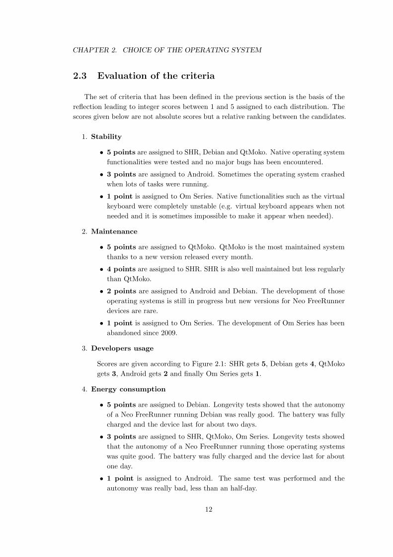
Table 2.1 summarizes the scores obtained by each candidate operating system for
each criterion and gives the total score.
Stability Maintenance Dev. usage Energy cons. Total
SHR 5 4 5 3 17
Debian 5 2 4 5 16
QtMoko 5 5 3 3 16
Android 1.5 3 2 2 1 8
Om Series 1 1 1 3 6
Table 2.1: This table summarizes the scores for each of the considered operating systemsaccording to the criteria proposed in Section 2.1.
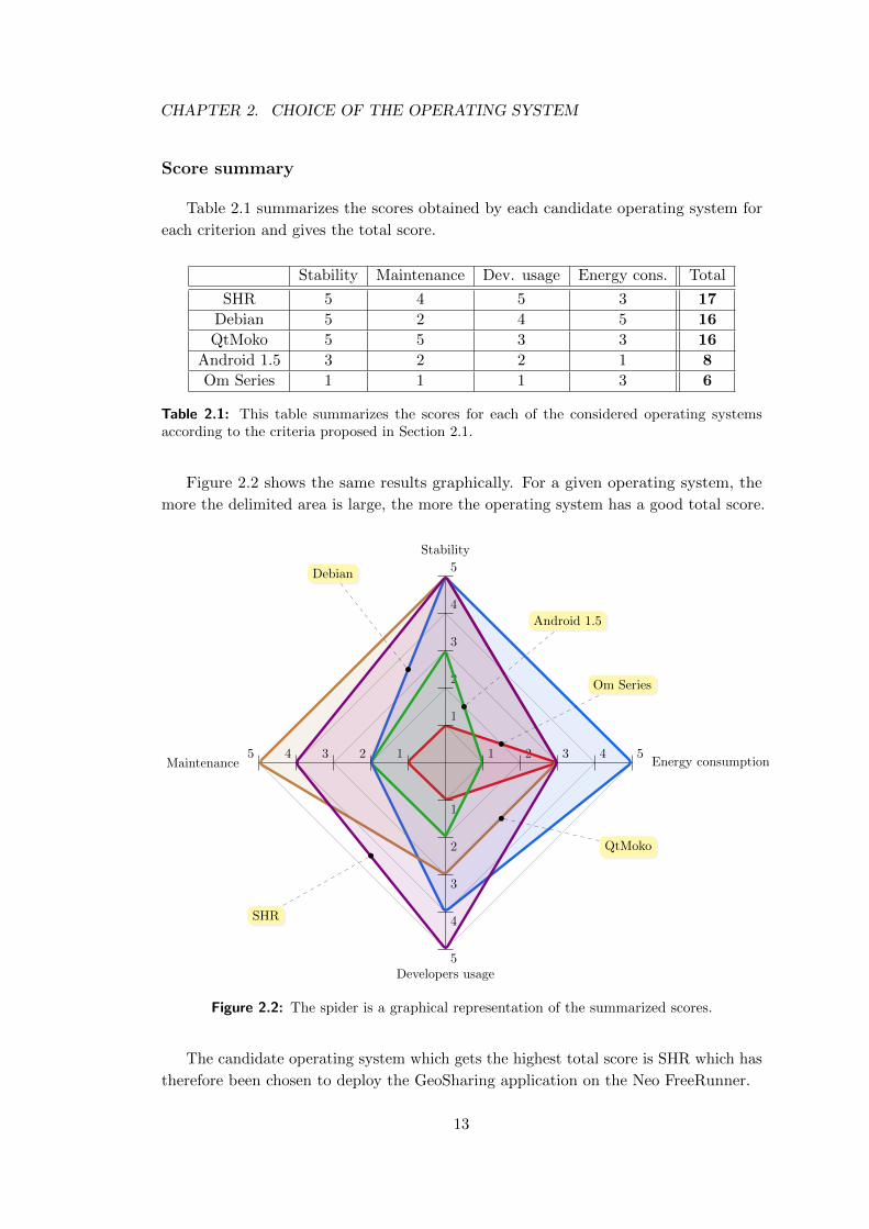
Figure 2.2 shows the same results graphically. For a given operating system, the
more the delimited area is large, the more the operating system has a good total score.
1
1
1
1
2
2
2
2
3
3
3
3
4
4
4
4
5
5
5
5
Energy consumptionMaintenance
Stability
Developers usage
Om Series
Android 1.5
Debian
QtMoko
SHR
Figure 2.2: The spider is a graphical representation of the summarized scores.
The candidate operating system which gets the highest total score is SHR which has
therefore been chosen to deploy the GeoSharing application on the Neo FreeRunner.
13
CHAPTER 2. CHOICE OF THE OPERATING SYSTEM
“SHR is a GNU/Linux based operating system for smartphones and similar
mobile devices. (...) SHR is based on OpenEmbedded and uses GNU/Linux
at its core. It integrates the freesmartphone.org framework for telephony,
networking, etc. (...) SHR is 100% community driven and based on Free
and Open Source Software.”
– Official SHR project website: http://www.shr-project.org
14
Chapter 3
Communication with the built-in
GPS module
This chapter presents the first part of the GeoSharing project. The problem that is
addressed is the interaction with the GPS module. Unlike the network part, described
in the next chapter, the interactions with the GPS module have only to be done in one
direction. The application must only be able to get information from the GPS module
and has never to send information to it besides control message to switch it on and off.
The first section describes the architecture of the GPS module on the Neo FreeRunner.
Then, the way the needed information are retrieved is explained. The last section presents
a brief analysis of the preciseness of the data obtained through the GPS module.
3.1 GPS communication stacks
This section details the different layers between an end-user application and the
hardware components involved when using the GPS module.
It is important to notice that there exists two main open-source GPS dæmons for
smartphones. The way the communication with the GPS dæmon is done depends on
the distribution installed on the phone.
These two dæmons are Gpsd and Ogpsd.
• Gpsd is used on some Om Series (2007 and 2008). Basically, this daemon is
the link between the GPS receiver (hardware) and a simple interface to allow
applications to retrieve position information. Gpsd communicates with upper
layers via a TCP/IP connection opened on port 2947. Gpsd can handle simple
requests on this socket and replies on the same socket.
• Ogpsd is used on Om Series built after 2008, and on Debian distributions. As
previously mentioned, SHR is a Debian-based distribution hence the application
15
CHAPTER 3. COMMUNICATION WITH THE BUILT-IN GPS MODULE
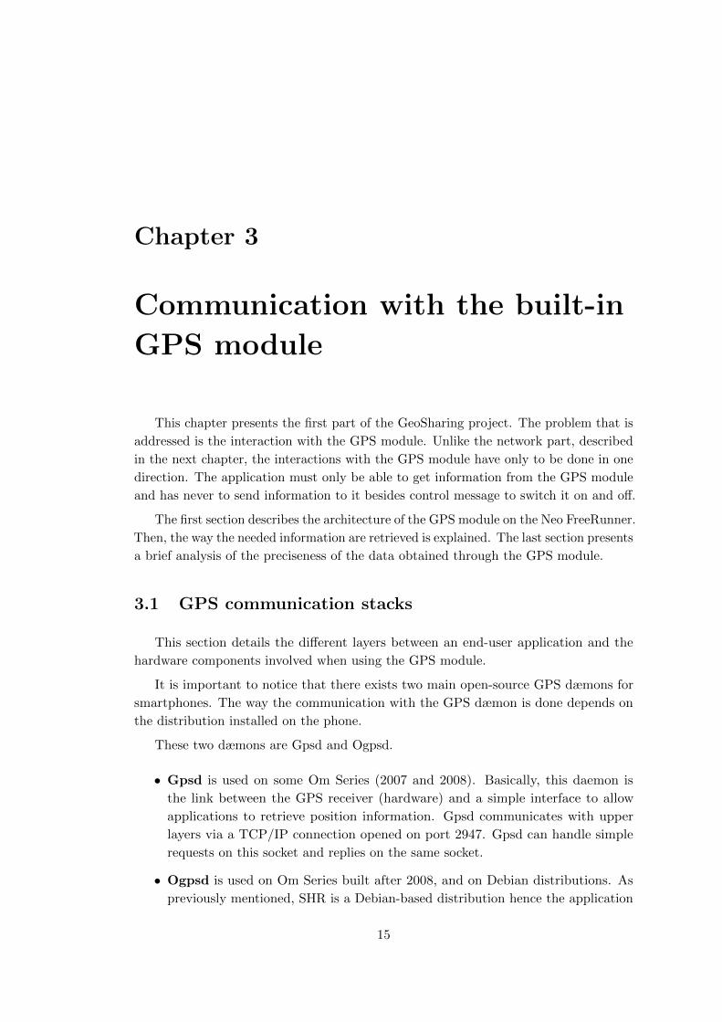
must deal with ogpsd in the scope of the GeoSharing project. Ogpsd differs from
gpsd in its behaviour in the sense that it does not use a TCP/IP connection
anymore but GPS data are retrieved through a D-Bus interface (Figure 3.1).
D-Bus is a software message bus system behaving like a hardware bus and allowing
applications to register on it to offer services to any other application such as in
service oriented architectures. The GPS module is registered on the bus and can
send GPS data on demand on this bus. Any application which wants to use this
information can read it on the bus.
Unfortunately, many end-user applications have been developed on top of gpsd and
have not been ported on ogpsd. To get rid of that problem, the FreeSmartphone.Org
(FSO) community has implemented a backward compatibility module called fso-gpsd.
This program runs on top of ogpsd in order to provide a TCP/IP interface to all
applications looking for that kind of connection.
Hardware GPS receiver
gpsd
TCP/IP
End-user application
Hardware GPS receiver
ogpsd
D-Bus
fso-gpsd
TCP/IP
End-user application
Figure 3.1: Gpsd and Ogpsd offer different connectivity modes.
3.2 Methods of geographical positions retrieval
This section presents different possibilities to get information about our position on
Earth. The first possibility is to use directly the D-Bus. The second one is to use the
TCP/IP connection opened on port 2947. Both solutions have been implemented in the
16
CHAPTER 3. COMMUNICATION WITH THE BUILT-IN GPS MODULE
GeoSharing project. Advantages and drawbacks of each solution are given hereafter.
When launching the GeoSharing application, it is possible to choose the method of
geographical positions retrieval by specifying dbus or tcp as argument. By default, the
D-Bus method is used. Details about launching GeoSharing are given in Appendix A.2.4.
3.2.1 D-Bus
The so-called D-Bus solution consists in accessing the D-Bus and reading for the
data. Fortunately there exists a library (called DBusGLib [DBu07]) allowing end-user
applications to read on the bus.
Once the connection with the bus is established, the interactions with it are done
through function calls. There exists an API listing all the possible calls on the D-
Bus [FSO11]. In the GeoSharing project, we only need one function call on the bus:
GetPosition() which is used to retrieve a data structure containing information about
the current GPS status such as the longitude, the latitude, the altitude, the number of
visible satellites, etc.
One advantage of the so-called D-Bus technique is that it only requires a short piece
of C code thanks to the already existing API’s. Another advantage is the fact that
the information is retrieved at a very low level of the architecture hence the number of
modules involved in the process is smaller than if the TCP/IP connection over fso-gpsd
is used. This smaller number thus reduces the probability of failures.
A drawback of the D-Bus technique is the fact that it is not generic (i.e all distribu-
tions do not implement de D-Bus interface).
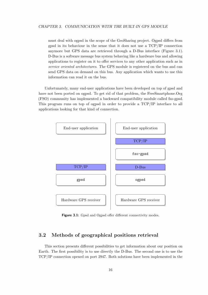
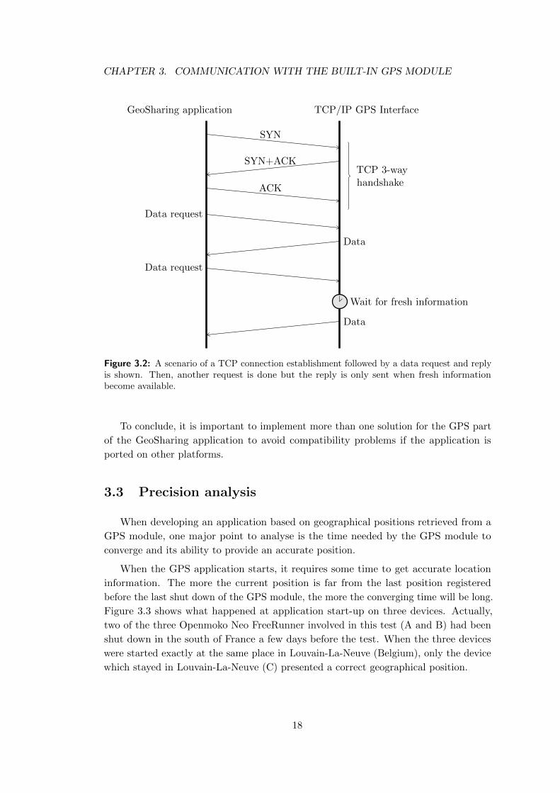
3.2.2 TCP/IP on port 2947
The so-called TCP/IP solution is a little bit more complex to implement but is still
easy to understand. The main idea is to open a local TCP connection on port 2947.
After the connection establishment, no packets are exchanged until the application
requests GPS data (Figure 3.2). Before sending the request, the application checks if
the socket responsible for port 2947 is ready to accept a request. If yes, the application
sends the request packet and waits for the reply. The same information are not sent
twice to the application hence this latter might be waiting until fresh information are
extracted from the GPS module.
One big advantage of this solution over the D-Bus one is the fact that it is more
generic. As we can see on Figure 3.1, whatever the GPS dæmon used, the ability to
establish a TCP/IP connection always exists. The TCP/IP connectivity can indeed be
found on top of Gpsd in one solution, and on top of fso-gpsd in the other solution.
A drawback of the TCP/IP technique is that it is not always optimal (i.e. it is
better to access a lower layer when possible).
17
CHAPTER 3. COMMUNICATION WITH THE BUILT-IN GPS MODULE
GeoSharing application TCP/IP GPS Interface
SYN
SYN+ACK
ACK
Data request
Data request
Data
Data
TCP 3-wayhandshake
Wait for fresh information
Figure 3.2: A scenario of a TCP connection establishment followed by a data request and replyis shown. Then, another request is done but the reply is only sent when fresh informationbecome available.
To conclude, it is important to implement more than one solution for the GPS part
of the GeoSharing application to avoid compatibility problems if the application is
ported on other platforms.
3.3 Precision analysis
When developing an application based on geographical positions retrieved from a
GPS module, one major point to analyse is the time needed by the GPS module to
converge and its ability to provide an accurate position.
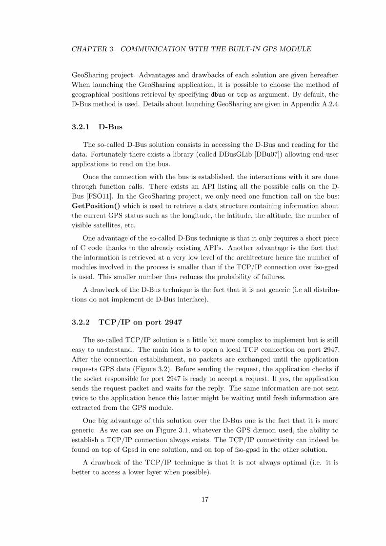
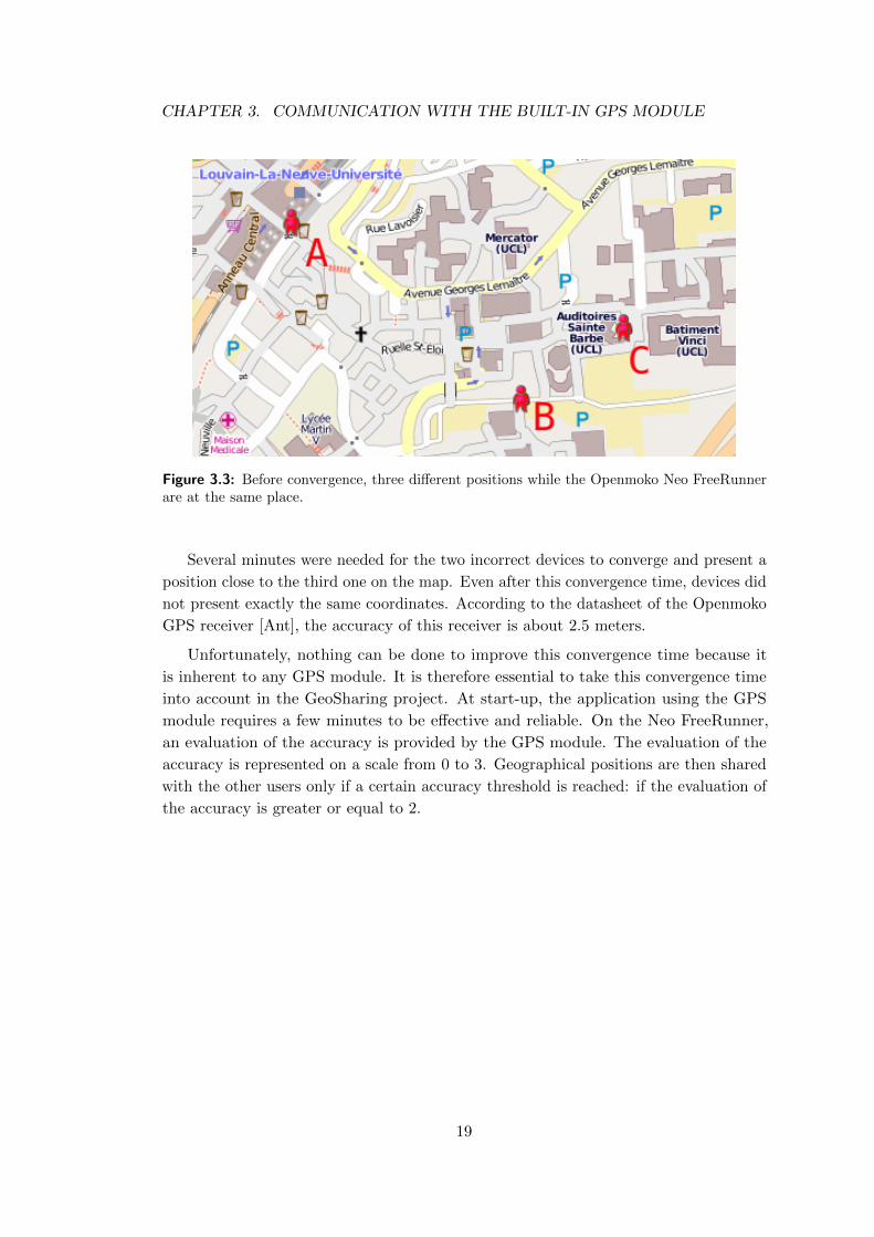
When the GPS application starts, it requires some time to get accurate location
information. The more the current position is far from the last position registered
before the last shut down of the GPS module, the more the converging time will be long.
Figure 3.3 shows what happened at application start-up on three devices. Actually,
two of the three Openmoko Neo FreeRunner involved in this test (A and B) had been
shut down in the south of France a few days before the test. When the three devices
were started exactly at the same place in Louvain-La-Neuve (Belgium), only the device
which stayed in Louvain-La-Neuve (C) presented a correct geographical position.
18
CHAPTER 3. COMMUNICATION WITH THE BUILT-IN GPS MODULE
Figure 3.3: Before convergence, three different positions while the Openmoko Neo FreeRunnerare at the same place.
Several minutes were needed for the two incorrect devices to converge and present a
position close to the third one on the map. Even after this convergence time, devices did
not present exactly the same coordinates. According to the datasheet of the Openmoko
GPS receiver [Ant], the accuracy of this receiver is about 2.5 meters.
Unfortunately, nothing can be done to improve this convergence time because it
is inherent to any GPS module. It is therefore essential to take this convergence time
into account in the GeoSharing project. At start-up, the application using the GPS
module requires a few minutes to be effective and reliable. On the Neo FreeRunner,
an evaluation of the accuracy is provided by the GPS module. The evaluation of the
accuracy is represented on a scale from 0 to 3. Geographical positions are then shared
with the other users only if a certain accuracy threshold is reached: if the evaluation of
the accuracy is greater or equal to 2.
19
Chapter 4
Network infrastructures and
protocols
The previous chapter describes how to retrieve geographical coordinates through
the GPS module in each Openmoko device. Since the ultimate goal of the GeoSharing
project is that each mobile system knows the absolute position1 of all the other mobile
systems, there is a need for an underlying network allowing to share this information.
This chapter is dedicated to the presentation of the reasoning about the networking
characteristics needed to spread the GPS coordinates between all the connected devices
in a reliable and efficient way. The first section introduces the requirements that need
to be satisfied by the Wi-Fi network on which the application relies. In the two next
sections, several Wi-Fi modes and routing protocols are introduced and the choices that
fit best the GeoSharing needs are selected, based on the pre-established requirements.
Section 4.4 presents security aspects to take into account when sharing personal data
on a network. The last section presents the implementation, in GeoSharing, of the
theoretical solutions that have been chosen.
4.1 Network requirements
The system to be developed is required to be autonomous and robust to failures with
a dynamic topology management. The system must indeed be deployable everywhere,
independently of infrastructures. This means that the entire network must be self-
managed by the Openmokos themselves. They have to be able to create the network
and broadcast the Service Set Identifier (SSID) of the network in order to allow other
devices to join it.
1 The absolute position means the position on Earth which is not to be confused with the relativeposition which can be the distance between two people.
20
CHAPTER 4. NETWORK INFRASTRUCTURES AND PROTOCOLS
Once the network has been created and all the Openmokos are interconnected,
coordinates of each system must be spread and made available to all the other systems.
Therefore, each node in the network must act as a router for the others. The application
that is to be developed is a real-time application, the position of each device belonging
to the network has to be updated as quickly as possible so that the system reflects the
reality as precisely as possible. In order to fulfil this requirement, an important required
point is a low forwarding delay for (re)transmissions of coordinates. Another important
point in order to build a real-time application is that the routing protocol should not
overload the network with its update packets. The bandwidth should be reserved for
data packets as much as possible.
The requirements can be summarized as follow.
1. Autonomy: the system should be deployable everywhere, independently of any
infrastructure;
2. Robustness and dynamism: the system has to be failure resistant and able to
self-manage the network topology;
3. Low forwarding delays: the system has to forward location data without
introducing delays (e.g. delays related to the changing network topology) in order
to follow the devices displacements as precisely as possible;
4. Reasonable bandwidth consumption for topology updates: the number
of update packets sent by the routing protocol should be kept as low as possible
in order to avoid losing data packets (containing location information) due to
network overloading.
4.2 Wi-Fi modes overview
This section first presents an overview of the different Wi-Fi connectivity modes.
The choice of the mode to be used in GeoSharing is presented and justified in the next
parts.
4.2.1 Wi-Fi connectivity modes
There exists two well known possible connectivity modes to create a Wi-Fi network.
• The most commonly used is the wireless infrastructure mode. It requires a wireless
access point operating as a router or a switch, to set this kind of network up. This
centralized solution is generally used at home or in companies in order to provide
an Internet connectivity to the users.
• The second mode is the wireless ad hoc mode. It allows multiple devices to be
interconnected without the need of external support.
21
CHAPTER 4. NETWORK INFRASTRUCTURES AND PROTOCOLS
Both solutions have advantages and drawbacks. The infrastructure mode indeed
provides a centralized solution which is easy to manage while the ad hoc mode is a
distributed solution more complicated to manage. It is especially the case for the
Dynamic Host Configuration Protocol (DHCP) which is responsible to distribute unique
IP addresses to all the nodes of a network. DHCP has to be distributed to work with
ad hoc networks. The security is also much more difficult to manage in a distributed
system. This latter point is discussed in Section 4.4.
In ad hoc networks, each node is susceptible to leave the network at any time. This
requires dynamic management of the topology for all nodes. Nodes can also join the
network at any time which will increase the load at each individual device as the number
of nodes increases. This is another limitation of this mode for small devices.
4.2.2 Wi-Fi mode choice
As just explained, both Wi-Fi connectivity modes present pros and cons. According
to the needs of the application presented at the beginning of this chapter, the ad hoc
mode is the more suitable. The infrastructure mode requires extra hardware to work
but this requirement is prohibited by the autonomy criteria. Besides, it confines all
devices within the radio range of the access point. Furthermore, the use of a centralized
solution such as in infrastructure mode makes the network less robust: if the access
point fails, the entire network will collapse. For those reasons, the ad hoc mode was
chosen to be used by the GeoSharing network.
4.2.3 Ad hoc mode overview
As Andreas Tønnesen explains in his master thesis [Tø04] and according to the
documentation found on Wikipedia, the free encyclopædia [Wir11], the wireless ad hoc
mode consists in a decentralized wireless network. It is called ad hoc because it does
not rely on any infrastructure such as router or access point. Basically, it allows two
entities located within range of each other to communicate. The decentralized nature of
ad hoc networks makes them more suitable for situations needing quick communication
establishment without relying on additional infrastructures. If ad hoc networks are well
suited for this kind of situations, they lack an important point. Ad hoc mode indeed
allows two neighbours that are in radio range to communicate. But in order to spread
the absolute location of each node through the network, a routing protocol whose aim
is to set up and maintain traffic paths along which each node location will flow is still
required. In the scope of this work, a protocol will be used to establish a self-configuring
infrastructure-less network intended for position forwarding. The combination of the ad
hoc network and its routing protocol is called Mobile Ad hoc NETwork (MANET).
22
CHAPTER 4. NETWORK INFRASTRUCTURES AND PROTOCOLS
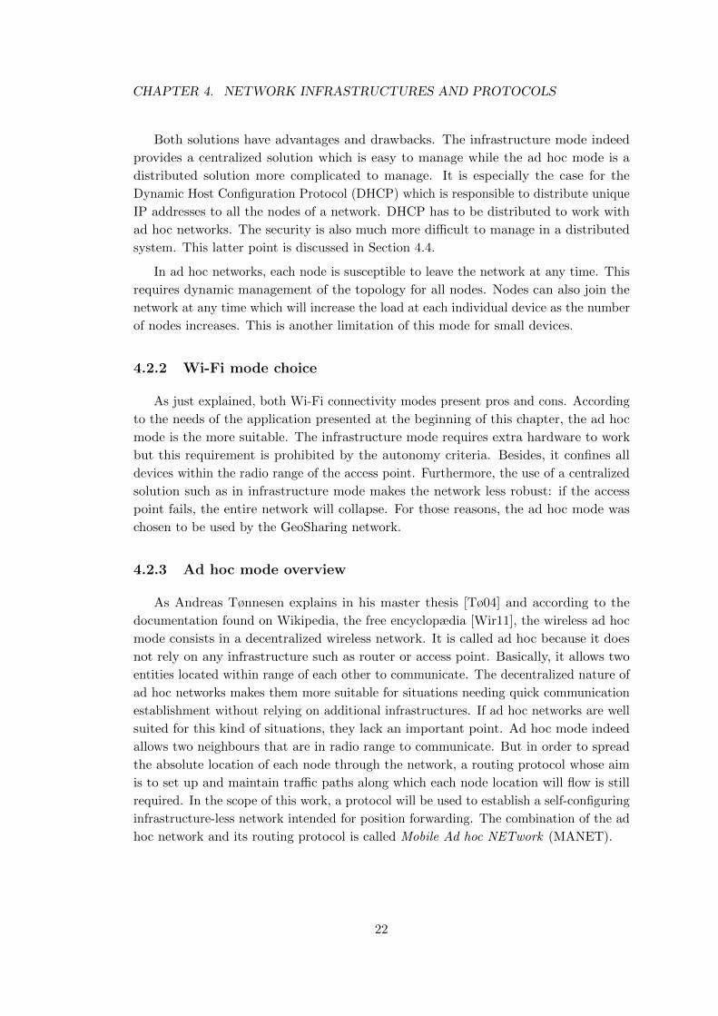
Figure 4.1 illustrates the topology of such a network. Node A can communicate
with node B via the intermediate nodes that act as routers to forward the traffic.
A
B
Figure 4.1: In this Mobile Ad hoc NETwork, node A can communicate with node B via theintermediate nodes.
DHCP in MANET
The DHCP issue in ad hoc networks (mentioned in Section 4.2.1) can be faced up
in four different ways. MANET does indeed not provide any centralized mechanism to
assign IP addresses to nodes joining the network. The four possible solutions to tackle
this DHCP issue are:
1. Manual IP address configuration.
Once a unique IP address has been attributed and set in the configuration files of
each mobile device, it does not require any more configuration and it is ready to
join the network at any time. Thanks to this manual configuration, it is possible
to maintain a matching table with owner-IP relationships.
2. Standard DHCP server on a centralized computer.
This solution consists in using a standard DHCP server on a centralized computer.
In order to get an IP address, each device must be in the radio range of the
centralized DHCP server. The DHCP lease time2 must be set to a high value (e.g.
more than one day). This long lease time ensures that, even if the DHCP server
goes out of the devices radio range, the MANET can still run correctly.
3. Standard DHCP server on an elected node.
This solution consists in using a standard DHCP server on one mobile device
connected to the network. In a network, there must only be one active DHCP
server at a time. Therefore, an election algorithm is used to determine which
2 The DHCP lease time is used to define how long an IP address is valid in the network.
23
CHAPTER 4. NETWORK INFRASTRUCTURES AND PROTOCOLS
node will be the DHCP server. This algorithm must provide exactly one solution
(i.e. the name or the reference of the elected node) whatever the network topology.
An example of an election process can be a process where the chosen node is the
one whose physical address of the interface connected to the network is the lowest.
Another election process would be to select the node closest to the center of the
network. Each node should therefore be able to act as a DHCP server since it is
susceptible to be selected by the algorithm.
4. Distributed algorithm.
This solution consists in using a distributed algorithm whose aim is to assign
an IP address to a new node joining the network. Each already connected node
in the network is asked to participate to the IP address choice. An example
of such a distributed algorithm for dynamic host configuration for MANETS is
MANETconf [NP02]. This algorithm is composed of two cases:
• When the very first node wants to join the network, the algorithm initializes
the MANET by assigning an IP address to this first node.
• When a new address demand is coming from a new node, every node already
connected to the network participate to the choice and the validation of the
IP address.
The first solution is the simplest one but is not user-friendly in the sense that the
change of the IP address of a device has to be performed by someone who knows where
interfaces configuration files are located in a Linux-based operating system. Besides this
drawback, this solution is fully effective. Furthermore, this solution does not require
any control message exchange for IP assignment hence the network bandwidth can be
dedicated to data packets instead of control packets. From a scalability standpoint, this
solution presents good performances since no additional process needs to be achieved
when the network is composed of thousands of nodes.
The second solution can be used only if the centralized DHCP server always remains
accessible. It is indeed impossible for a totally new node to get an IP address if the
DHCP server is out of range. It can especially be a problem in the military domain
where soldiers must be able to set up the MANET anywhere, without relying on any
external or centralized infrastructure.
The third solution is the less efficient one especially on small devices such as the Neo
FreeRunner. The fact that, after the election, the IP address assignment process relies
on a single device makes this solution less robust to failures (especially if the elected
device fails or gets out of range of any other node of the network). Moreover, during the
election phase, a part of the network bandwidth is used by control messages. Finally,
the scalability of this solution depends on the scalability of the election algorithm. If
the number of devices increases a lot, the amount of generated traffic for each election
can indeed become hard to support to fit the network bandwidth.
24
CHAPTER 4. NETWORK INFRASTRUCTURES AND PROTOCOLS
The fourth solution is entirely distributed. According to [NP02], MANETconf, which
is a distributed dynamic host configuration protocol, is reliable, message losses tolerant
and scalable. But, the scalability analysis proposed in the paper is only based on the
number of exchanged messages while the network state (that each node must maintain)
must also be part of the analysis. The network state stored inside each node can indeed,
as well as the number of exchanged packets, lead to scalability issues.
In the scope of the GeoSharing project, the first solution (i.e. the manual configuration)
is used mainly for its easiness. Moreover, Neo FreeRunner devices used in this project
have relatively small CPUs hence all not mandatory CPU usage is avoided. The
implementation of one of the other possible choices can be the focus of further work.
4.3 Routing protocols overview
At this point, the general working concepts of the network have been defined. This
section focuses on the routing protocol that will be used to set up and maintain traffic
paths. The protocol choice is important because of the bandwidth limitation due to the
wireless technology used in mobile devices.
Some of the most popular routing protocols available for an ad hoc wireless network
are analysed in this section. But before going any further, distance vector and link-state
routing concepts are introduced since they will be used in the remaining of this chapter.
4.3.1 Distance vector vs. link-state routing
There are two well known classes of distributed routing protocols which are distance
vector and link-state routing. This section presents them since they introduce some
technical background used in the following sections. Readers that are already familiar
with those classes of routing protocols may safely skip this section and directly go to
Section 4.3.2.
Distance vector routing
Distance vector routing is a very simple class of distributed routing protocols based
on the advertisement of the distance from the originator towards each known destination.
It uses a distributed algorithm to compute the shortest path towards each destination.
“Distance vector routing allows the routers to automatically discover the
destinations that are reachable inside the network and the shortest path to
reach each of these destinations. The shortest path is computed based on
metrics or costs that are associated to each link. (...) Each router maintains
25
CHAPTER 4. NETWORK INFRASTRUCTURES AND PROTOCOLS
a routing table. The routing table R can be modelled as a data structure that
stores, for each known destination address d, the following attributes :
• R[d].link is the outgoing link that the router uses to forward packets
towards destination d
• R[d].cost is the sum of the metrics of the links that compose the shortest
path to reach destination d
• R[d].time is the timestamp of the last distance vector containing desti-
nation d
A router that uses distance vector routing regularly sends its distance vector
over all its interfaces. The distance vector is a summary of the router’s
routing table that indicates the distance towards each known destination.”
– Prof. Olivier Bonaventure [Bon11]
As it is explained in the book of Prof. Olivier Bonaventure [Bon11], the timestamp
is used to detect link failures. Each entry of the routing table should be updated every
N seconds, but in case of failure it is no more the case. Routers check every N seconds
the timestamps of the routes stored in their routing table and remove those which are
older than 3×N seconds. This class of protocols suffers from a problem that is known
as the count to infinity problem in the networking literature. This means that nodes
update their tables based on old information present in the network. Some solutions,
such as split horizon with poison reverse, exist and reduce the bad behaviour introduced
by this problem, but they do not solve it entirely.
Link-state routing
Another class of distributed routing protocols is the category of link state routing
protocols. Unlike distance vector, every router belonging to the network learns the
entire topology via message exchanges and the shortest path is computed locally thanks
to the Dijkstra’s shortest path algorithm.
“For link-state routing, a network is modelled as a directed weighted graph.
Each router is a node and the links between routers are the edges in the
graph. A positive weight is associated to each directed edge and routers use
the shortest path to reach each destination.”
– Prof. Olivier Bonaventure [Bon11]
In this kind of routing, each router automatically discovers its neighbours by the
use of HELLO packets that are sent every N seconds on all its interfaces. When
receiving HELLO packets, a router knows to which neighbours it is connected. These
HELLO packets are never forwarded and they can also be used to detect link failures.
26
CHAPTER 4. NETWORK INFRASTRUCTURES AND PROTOCOLS
“Once a router has discovered its neighbours, it must reliably distribute its
local links to all routers in the network to allow them to compute their local
view of the network topology. For this, each router builds a link-state packet
(LSP) (...)
As the LSPs are used to distribute the network topology that allows routers
to compute their routing tables, routers cannot rely on their non-existing
routing tables to distribute the LSPs. Flooding is used to efficiently distribute
the LSPs of all routers. Each router that implements flooding maintains a
link state database (LSDB) that contains the most recent LSP sent by each
router. When a router receives a LSP, it first verifies whether this LSP is
already stored inside its LSDB. If so, the router has already distributed the
LSP earlier and it does not need to forward it. Otherwise, the router forwards
the LSP on all links except the link over which the LSP was received.”
– Prof. Olivier Bonaventure [Bon11]
Distance vector and link-state routing protocols have been presented in a succinct
way such that readers that are unfamiliar with these concepts can understand the next
part of this section. These explanations are based on the document of Prof. Olivier
Bonaventure. If you are interested in these protocols and want deeper details, you can
read the original document [Bon11].
4.3.2 Underlying routing protocols
Now that the prerequisites have been introduced, the main routing protocols that
can be deployed on ad hoc networks are presented. According S. Langkemper [Lan06],
there exists two main types of routing protocols: proactive and reactive routing. This
section is devoted to the presentation of routing protocols from those two main classes
in order to choose the one that fits the most the needs of the application.
Proactive routing
Proactive routing protocols try to keep the routing table up-to-date on every node
belonging to the network. The advantage of this kind of protocols is the fast forwarding
times, because all the information for packet routing is available and up-to-date when a
packet has to be sent. The main drawback is the continuous bandwidth consumption
to spread routing information through the network, even when no data are exchanged
between the nodes.
The main routing protocols from this class are: Distributed Bellman-Ford, Optimized
Link State Routing, Global State Routing, Fisheye State Routing and Hazy Sighted
Link State.
27
CHAPTER 4. NETWORK INFRASTRUCTURES AND PROTOCOLS
Distributed Bellman-Ford [Lan06] (DBF) belongs to the distance vector class,
each node sends a routing table periodically to its neighbours. This routing table
contains all the information known by the sender about the distance to reach each
discovered in the network, at the time of sending. When a node receives a routing
table, it updates its own routing table and only keeps the shortest path to reach each
destination. Since this algorithm belongs to the distance vector routing class, it suffers
from count-to-infinity problem. Ad hoc network topology is subject to frequent changes
since nodes can move or fail. This routing protocol is therefore considered as unsuitable.
Optimized Link State Routing (OLSR) is an experimental protocol defined in
RFC3626 [CJ03] which is similar to link-state routing. Each node selects some nodes
in its neighbourhood which are called Multipoint Relays (MPRs). RFC3626 defines a
mechanism to select the MPRs. These nodes will only forward messages from the node
which have selected it as an MPR. Update messages are flooded over the entire network
just as in link-state, but now only the MPRs relay the messages, decreasing the overall
bandwidth consumption.
Global State Routing [Glo11] (GSR) is based on link-state routing. It does not
flood link state packets through the entire network each time the topology changes
but uses instead a periodic exchange of Link-State Packet (LSP) information, which
reduces the control overhead. This packet contains a representation of the entire network
topology and is only sent to neighbours. Each node can then compute the shortest paths
(thanks to Dijkstra Shortest Path algorithm) using the information contained in the
LSP. Since no global flooding is used, GSR greatly reduces the number of packets sent
through the network when a node disconnects/reconnects. The fact that GSR depends
on time for the update of the routing information, and is no more event-based, makes
the update frequency a critical parameter that must be carefully chosen as discussed by
Tsu-Wei Chen and Mario Gerla [CG98].
Fisheye State Routing (FSR) is an improvement of GSR described by G. Pei, M.
Gerla and Tsu-Wei Chen in [PGC00]. With this protocol, nodes also only sends packets
to direct neighbours. This protocol assumes that routes to nodes that are far are less
important than routes to close nodes.
“In FSR, every update message doesn’t contain information about all nodes
in the network. Instead, information about closer nodes is exchanged more
frequently than it is done about farther nodes, thus reducing the update
message size. The center node has most up to date information about all
nodes in the inner circle and the accuracy of information decreases as the
distance from node increases.”
– SECAN-Lab (University of Luxembourg) [Fis11]
28
CHAPTER 4. NETWORK INFRASTRUCTURES AND PROTOCOLS
The routing table is accurate for close nodes but less precise for distant nodes. When
a data packet is sent, since it goes from node to node, the route followed is reprecised
at each node encountered along the path followed. Local changes are detected faster
than distant changes according to the update period that has been defined.
Since both GSR and FSR only transmit information to their direct neighbours
depending on the update period, it may take a long time before a topology change get
communicated to the entire network.
Hazy Sighted Link State [SR03] (HSLS) also assumes that local changes of topol-
ogy are more important than what is happening far away, as in FSR. While FSR is only
based on an update period to delay the forwardings, Hazy Sighted Link State also has
a time-to-live (TTL) to limit the spreading of LSPs through the network. This value
is decreased by one in each packet which is forwarded and a packet with a zero value
for the TTL is no more forwarded. Since this algorithm is also based on an update
period, the neighbouring nodes will receive periodic updates (every N second(s)). This
update messages will be forwarded at every update period, meaning that the next
nodes will receive the update with an additional delay and a TTL value that has been
decremented. Therefore, direct neighbours of the origin will receive update information
every N second(s), next-hop will also receive these update information but, delayed of
2×N seconds, etc. So, close nodes will be aware of changes quickly while more distant
nodes will receive update information less often. A long time can so be elapsed before a
change is spread through the entire network.
Reactive routing
In opposition to proactive routing, reactive (or on-demand) routing protocols do
not keep a routing table up-to-date but the path towards the destination is computed
whenever a packet has to be sent. This technique reduces the bandwidth consumption
since no update packets are sent, unless data are sent. It does not fit well mobile
networks because flooding is used when a link fails, which happens frequently in mobile
networks due to topology changes. So, flooding occurs very often and therefore reactive
routing becomes close to link-state routing (where flooding is periodic). Furthermore, a
delay is introduced when the first packet is sent to a host because of route computation.
This class of routing protocols is implemented by multiple routing protocols among
which one can find: Ad hoc On-demand Distance Vector protocol and Dynamic Source
Routing which are the two most common reactive protocols.
Ad hoc On-demand Distance Vector protocol (AODV) is an experimental pro-
tocol defined in RFC3561 [PBRD03]. It uses route request (RREQ) packets that are
flooded throughout the entire network to discover the destination host. When a host
receives a RREQ, it caches the route back to the originator in order to be able to unicast
29
CHAPTER 4. NETWORK INFRASTRUCTURES AND PROTOCOLS
the route reply (RREP). As said previously, this category of protocols is not really
efficient when used in dynamic networks. Indeed, when a RREQ is emitted, each node
will get it. It is an expensive mechanism, especially if the requested destination does not
exists. In ad hoc networks, topology changes are frequent. This implies that a significant
part of the bandwidth will be devoted to route requests and not for application data
transfer. Furthermore, all these requests introduce an additional delay, just to find a
path to reach the destination.
Dynamic Source Routing (DSR) is an experimental protocol defined in
RFC4728 [JHM07]. This protocol uses what is called source routing, meaning that
each data packet that is sent contains the complete list of hops in the same order it
passes through them. In order to find a path towards a certain node, the originator will
broadcast a route discovery packet. Each neighbouring node will append its address
to the list and broadcast the packet in turn. Once the destination node receives the
route request packet, the list contains a path from the source to the destination. The
destination node will then send the route request packet back to the source node via the
reverse path contained in the packet. Source routing allows the source node to select the
route it will use to send its data packets among the received ones and since the entire
path is contained in the packet, it is easy to select a loop-free path. The main difference
with AODV is that DSR does not cache the route towards which a node should send
data back to the source node because everything is inside the packet. The advantage of
DSR is that no control message packets are sent on the network periodically, reducing
the network load.
4.3.3 Routing protocol choice
As presented previously, reactive routing protocols introduce more delays than
proactive routing protocols. Since the third requirement (Section 4.1 on page 21) of
the application is low forwarding delays, AODV and DSR are discarded. Even if more
packets are used to keep each node of the network aware of the entire topology, proactive
routing seems to be the best solution for the GeoSharing application. Because the
wireless ad hoc network is made of small mobile devices, the bandwidth used for topology
management should be minimized. Another point to take into account is that wireless
technology of such devices is prone to lots of losses and so redundancy is required. There
remains six different routing protocols belonging to the proactive routing class. As
explained in Section 4.3.1, distance vector is subject to the count-to-infinity problem
even with additional techniques such as split horizon with poison reverse. Therefore
only link-state routing protocols are kept as possible choices.
Two more criteria are important for de developed application: forwarding delays
and bandwidth consumption for topology updates. The following compares the three
remaining possible choices.
30
CHAPTER 4. NETWORK INFRASTRUCTURES AND PROTOCOLS
GSR and FSR improve the bandwidth usage but introduce delays in the topology
update by transmitting information to their direct neighbours depending on the update
period. It may therefore take a while before the topology is updated in the entire
network.
Hazy Sighted Link State also improves the bandwidth limitation but still has a
problem very similar to GSR and FSR. Nodes that are quite far receive update messages
after a relatively long period of time such that these nodes do not have recent information
about whether a distant node is still present or not.
Optimized Link State Routing combines the advantages of proactive and reactive
routing. That is to say, routing tables are always up-to-date thank to the global flooding
technique and bandwidth consumption related to this flooding is reduced via the use of
MPRs.
In light of the previous analysis, it appears that Optimized Link State Routing is the
most suitable protocol for the GeoSharing application. It indeed keeps routing tables of
every node up-to-date and reduces the number of update packets by the use of MPRs.
Consequently, we choose this protocol as routing protocol in the GeoSharing MANET.
4.3.4 Optimized Link State Routing protocol in details
The Optimized Link State Routing protocol has been developed for MANETs. It is
a proactive routing protocol as it has been explained in Section 4.3.2. Routing tables
are therefore maintained up-to-date thanks to control traffic forwarding mechanism.
The control messages are relayed by MPRs. This protocol suits very well for large and
dense networks. The optimization achieved is better and better as the network becomes
bigger and more dense (compared to a classical link-state protocol). OLSR fits very
well the GeoSharing application because it has been designed to work in a distributed
environment without relying on any centralized infrastructure.
Losses are frequent in wireless environment due to collision, electromagnetic interfer-
ences, etc. Nevertheless, OLSR does not require retransmission mechanism. A sequence
number, which is incremented for each new message, is joined to every control message
sent such that the receiver can check if the received message is the most recent or not
and discards it if needed. OLSR relies on UDP on port 698 that has been assigned by
the Internet Assigned Numbers Authority (IANA) to send packets. The protocol has
been initially designed for IP version 4 (IPv4). But, it requires only a few modifications
in the address lengths, in packet and message sizes to be IP version 6 (IPv6) compliant.
31
CHAPTER 4. NETWORK INFRASTRUCTURES AND PROTOCOLS
Another important feature of OLSR is its compatibility to extensions. Extensions
(such as security and multicast-routing modules) can be used in combination with the
standard OLSR protocol whose main purpose is to provide routing in a stand-alone
MANET.
Multipoint Relays selection
Until this point, the assumption that MPRs are selected in an optimal way in order
to establish connectivity between all nodes of the network was made. This paragraph
briefly describes the way MPRs are chosen.
The optimal selection of the MPRs is an NP-complete problem. There exists
heuristics to calculate a good-enough solution. In current OLSR implementation, Simple
Greedy MPR Heuristic is used. Before starting any development, let’s introduce the
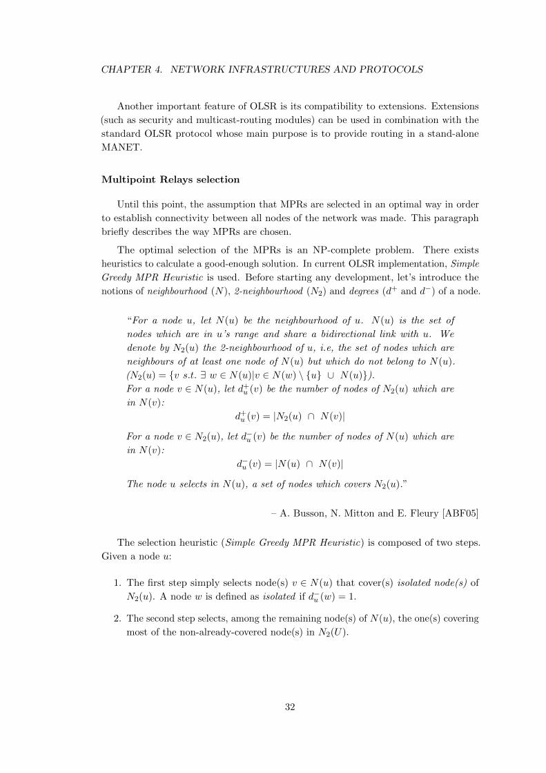
notions of neighbourhood (N), 2-neighbourhood (N2) and degrees (d+ and d−) of a node.
“For a node u, let N(u) be the neighbourhood of u. N(u) is the set of
nodes which are in u’s range and share a bidirectional link with u. We
denote by N2(u) the 2-neighbourhood of u, i.e, the set of nodes which are
neighbours of at least one node of N(u) but which do not belong to N(u).
(N2(u) = {v s.t. ∃ w ∈ N(u)|v ∈ N(w) \ {u} ∪ N(u)}).
For a node v ∈ N(u), let d+u (v) be the number of nodes of N2(u) which are
in N(v):
d+u (v) = |N2(u) ∩ N(v)|
For a node v ∈ N2(u), let d−u (v) be the number of nodes of N(u) which are
in N(v):
d−u (v) = |N(u) ∩ N(v)|
The node u selects in N(u), a set of nodes which covers N2(u).”
– A. Busson, N. Mitton and E. Fleury [ABF05]
The selection heuristic (Simple Greedy MPR Heuristic) is composed of two steps.
Given a node u:
1. The first step simply selects node(s) v ∈ N(u) that cover(s) isolated node(s) of
N2(u). A node w is defined as isolated if d−u (w) = 1.
2. The second step selects, among the remaining node(s) of N(u), the one(s) covering
most of the non-already-covered node(s) in N2(U).
32
CHAPTER 4. NETWORK INFRASTRUCTURES AND PROTOCOLS
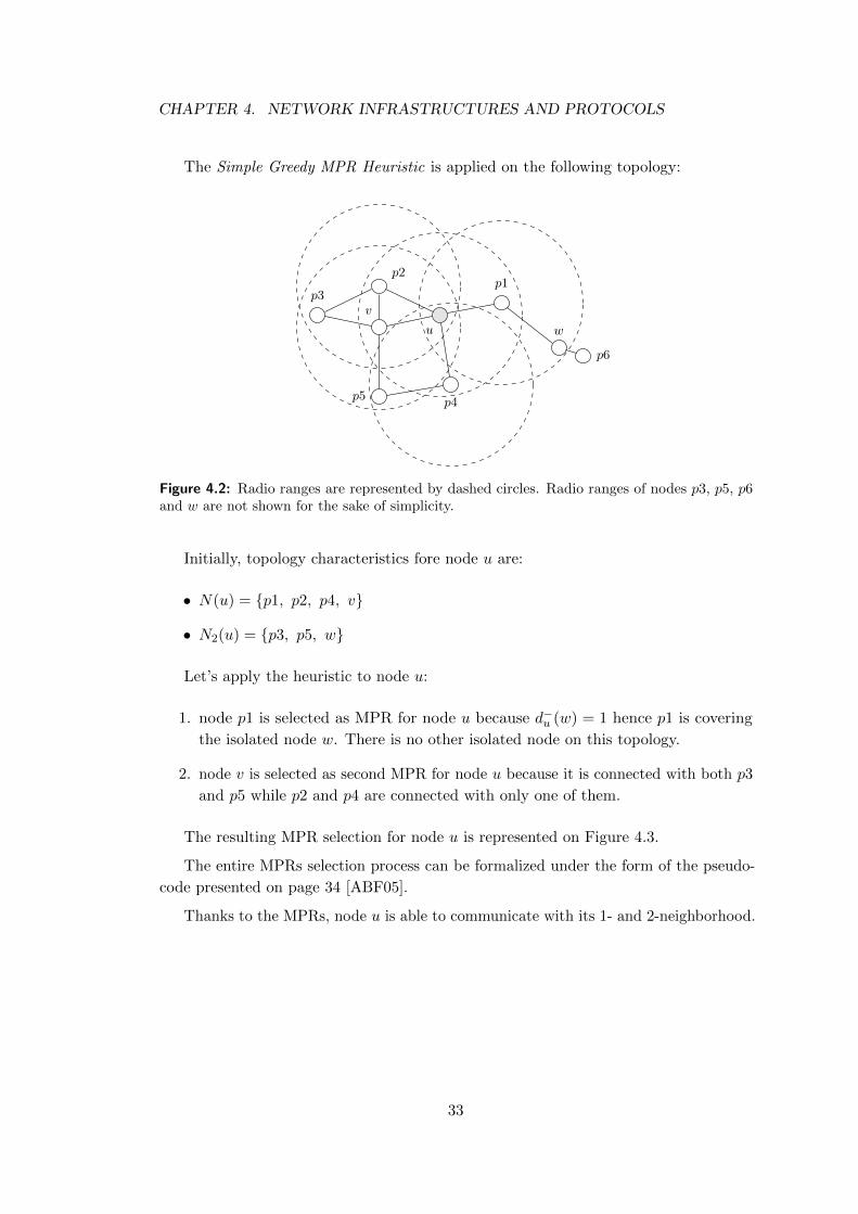
The Simple Greedy MPR Heuristic is applied on the following topology:
u
p1
w
v
p2
p3
p4p5
p6
Figure 4.2: Radio ranges are represented by dashed circles. Radio ranges of nodes p3, p5, p6and w are not shown for the sake of simplicity.
Initially, topology characteristics fore node u are:
• N(u) = {p1, p2, p4, v}
• N2(u) = {p3, p5, w}
Let’s apply the heuristic to node u:
1. node p1 is selected as MPR for node u because d−u (w) = 1 hence p1 is covering
the isolated node w. There is no other isolated node on this topology.
2. node v is selected as second MPR for node u because it is connected with both p3
and p5 while p2 and p4 are connected with only one of them.
The resulting MPR selection for node u is represented on Figure 4.3.
The entire MPRs selection process can be formalized under the form of the pseudo-
code presented on page 34 [ABF05].
Thanks to the MPRs, node u is able to communicate with its 1- and 2-neighborhood.
33
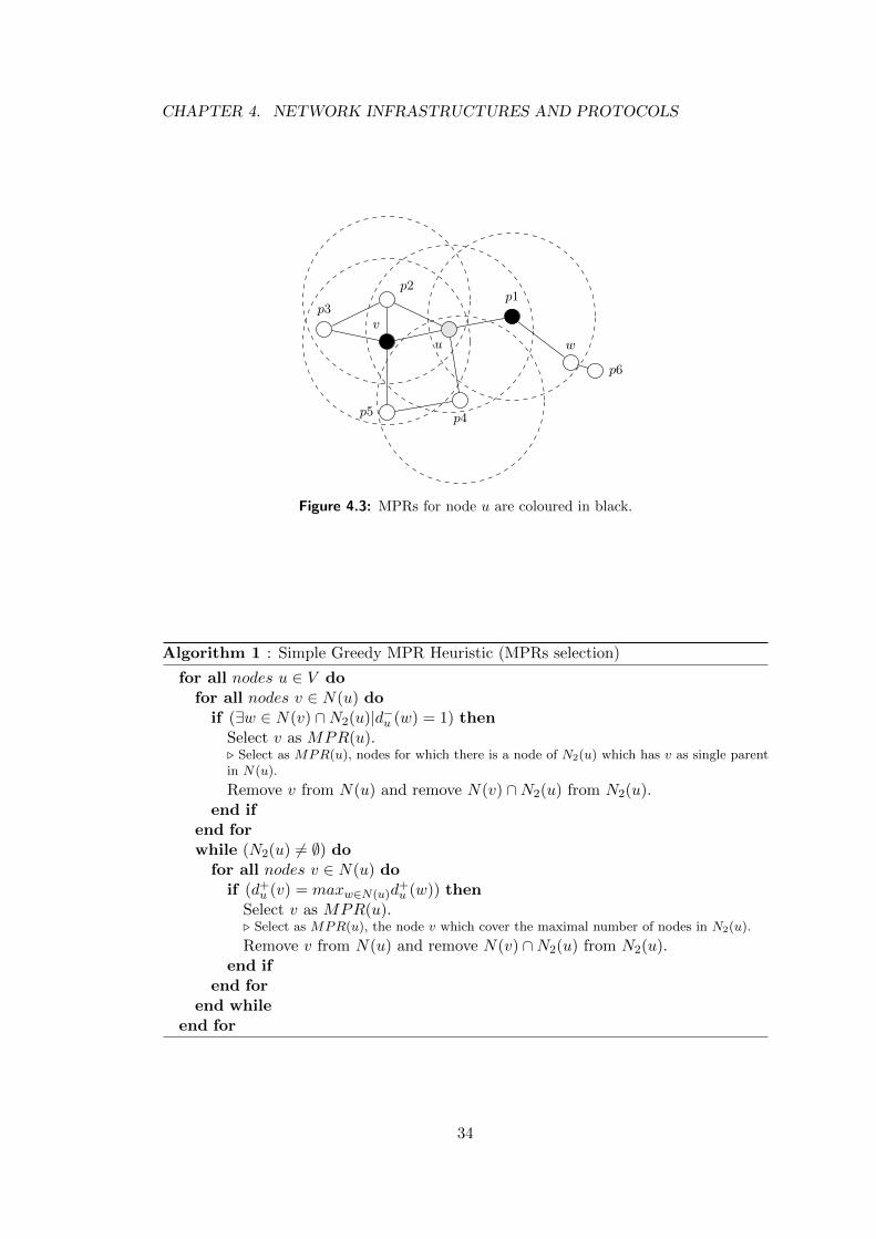
CHAPTER 4. NETWORK INFRASTRUCTURES AND PROTOCOLS
u
p1
w
v
p2
p3
p4p5
p6
Figure 4.3: MPRs for node u are coloured in black.
Algorithm 1 : Simple Greedy MPR Heuristic (MPRs selection)
for all nodes u ∈ V dofor all nodes v ∈ N(u) do
if (∃w ∈ N(v) ∩N2(u)|d−u (w) = 1) thenSelect v as MPR(u).. Select as MPR(u), nodes for which there is a node of N2(u) which has v as single parentin N(u).
Remove v from N(u) and remove N(v) ∩N2(u) from N2(u).end if
end forwhile (N2(u) 6= ∅) do
for all nodes v ∈ N(u) doif (d+u (v) = maxw∈N(u)d
+u (w)) then
Select v as MPR(u).. Select as MPR(u), the node v which cover the maximal number of nodes in N2(u).
Remove v from N(u) and remove N(v) ∩N2(u) from N2(u).end if
end forend while
end for
34
CHAPTER 4. NETWORK INFRASTRUCTURES AND PROTOCOLS
4.4 Secured data transfer
Security is a core problem in network technologies, in particular in wireless network
technologies. By nature, radio waves can be eavesdropped on by anyone who is in the
radio range. Since the GeoSharing application is based on this wireless technology,
some mechanisms should be added to prevent illegitimate persons to steal geo-location
information or to send data over the network and potentially taking the control of it. For
the GeoSharing application, the data packets flowing through the network contain the
absolute positions of the devices on Earth. Since the application field could be sensitive,
it is important to preserve the privacy of the users. The application is therefore designed
so as to restrict the access to these sensitive data only to authorized persons.
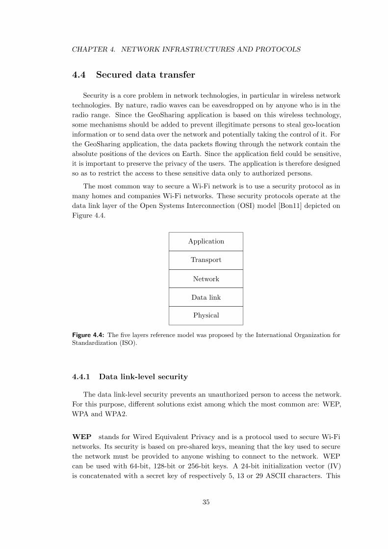
The most common way to secure a Wi-Fi network is to use a security protocol as in
many homes and companies Wi-Fi networks. These security protocols operate at the
data link layer of the Open Systems Interconnection (OSI) model [Bon11] depicted on
Figure 4.4.
Application
Transport
Network
Data link
Physical
Figure 4.4: The five layers reference model was proposed by the International Organization forStandardization (ISO).
4.4.1 Data link-level security
The data link-level security prevents an unauthorized person to access the network.
For this purpose, different solutions exist among which the most common are: WEP,
WPA and WPA2.
WEP stands for Wired Equivalent Privacy and is a protocol used to secure Wi-Fi
networks. Its security is based on pre-shared keys, meaning that the key used to secure
the network must be provided to anyone wishing to connect to the network. WEP
can be used with 64-bit, 128-bit or 256-bit keys. A 24-bit initialization vector (IV)
is concatenated with a secret key of respectively 5, 13 or 29 ASCII characters. This
35
CHAPTER 4. NETWORK INFRASTRUCTURES AND PROTOCOLS
protocol is broken since 2001 [FMS01] and today, it is possible to retrieve the key of a
network protected with the WEP standard in a few seconds. Using WEP is generally
better than letting the network open (i.e. without any security). If an attacker makes
use of a packet stolen on a WEP-secured network, she implicitly admits having cracked
the network in order to steal the packet. WEP is therefore nowadays more a mechanism
to force attackers to do something illegal (i.e. wireless network cracking) when they
want to steal information on a WEP-secured network.
WPA stands for Wi-Fi Protected Access. It is an improvement and a provisional
solution to WEP. The main differences are the use of an initialization vector of 48 bits
instead of 24 for WEP and the implementation of a layer on top of WEP called Temporal
Key Integrity Protocol (TKIP). TKIP allows the system to dynamically change the key.
This combination allows the protocol to be resistant to attacks developed against WEP.
WPA is thus much stronger than WEP, although security breaches have been found in
the TKIP algorithm used in WPA.
WPA has been designed to operate in two different modes. The first mode is called
the WPA-Personal mode or WPA-PSK for Pre-Shared Key. It works exactly as the
WEP encryption mode using a 256-bit key, but is more robust than WEP thanks to
the TKIP mechanism and the longer IV. The other mode relies on a RADIUS server
and is called the WPA-Enterprise mode. The user has to provide its credential to the
RADIUS server and it receives a session key back. This mode is more complicated to
set up in a MANET due to the centralised RADIUS server. Hence, the WPA-Enterprise
mode is not considered in the scope of the GeoSharing project.
WPA2 is the successor to the provisional WPA protocol. WPA2 defines a certification
that has to be satisfied by all new devices to be compliant with the Wi-Fi standard. It
uses an even stronger encryption algorithm than WPA. WPA2 is believed to be only
sensitive to brute force or dictionary attacks. Therefore, if a good password3 is chosen,
a WPA2-secured system can be considered to be secure.
In order to establish a WPA2-secured ad hoc network, the authentication process
requires that each node acts as a client and a server for the other nodes. The WPA2
security scheme has not yet been deployed in the GeoSharing project. The deployment
of this security scheme could be part of another study about security in MANET.
Nevertheless, a reliable solution can be built based on WEP security (which is easier to
achieve in ad hoc networks) combined with additional security mechanisms implemented
in the application layer of the OSI model (Figure 4.4).
3 A password is considered as good if made of a hard to guess combination of different types ofcharacters such as upper and lower case letters, numbers and punctuation marks. It should not befound in any dictionary of any language.
36
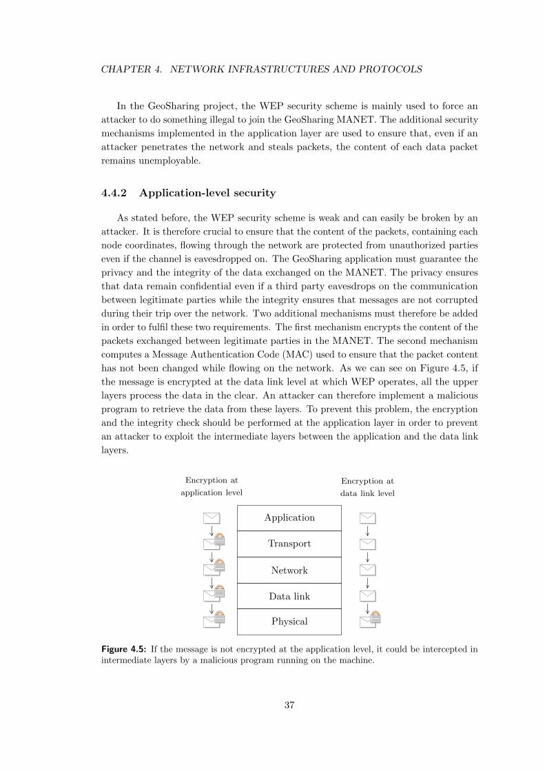
CHAPTER 4. NETWORK INFRASTRUCTURES AND PROTOCOLS
In the GeoSharing project, the WEP security scheme is mainly used to force an
attacker to do something illegal to join the GeoSharing MANET. The additional security
mechanisms implemented in the application layer are used to ensure that, even if an
attacker penetrates the network and steals packets, the content of each data packet
remains unemployable.
4.4.2 Application-level security
As stated before, the WEP security scheme is weak and can easily be broken by an
attacker. It is therefore crucial to ensure that the content of the packets, containing each
node coordinates, flowing through the network are protected from unauthorized parties
even if the channel is eavesdropped on. The GeoSharing application must guarantee the
privacy and the integrity of the data exchanged on the MANET. The privacy ensures
that data remain confidential even if a third party eavesdrops on the communication
between legitimate parties while the integrity ensures that messages are not corrupted
during their trip over the network. Two additional mechanisms must therefore be added
in order to fulfil these two requirements. The first mechanism encrypts the content of the
packets exchanged between legitimate parties in the MANET. The second mechanism
computes a Message Authentication Code (MAC) used to ensure that the packet content
has not been changed while flowing on the network. As we can see on Figure 4.5, if
the message is encrypted at the data link level at which WEP operates, all the upper
layers process the data in the clear. An attacker can therefore implement a malicious
program to retrieve the data from these layers. To prevent this problem, the encryption
and the integrity check should be performed at the application layer in order to prevent
an attacker to exploit the intermediate layers between the application and the data link
layers.
Application
Transport
Network
Data link
Physical
Encryption at
application level
Encryption at
data link level
Figure 4.5: If the message is not encrypted at the application level, it could be intercepted inintermediate layers by a malicious program running on the machine.
37
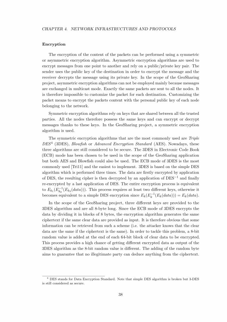
CHAPTER 4. NETWORK INFRASTRUCTURES AND PROTOCOLS
Encryption
The encryption of the content of the packets can be performed using a symmetric
or asymmetric encryption algorithm. Asymmetric encryption algorithms are used to
encrypt messages from one point to another and rely on a public/private key pair. The
sender uses the public key of the destination in order to encrypt the message and the
receiver decrypts the message using its private key. In the scope of the GeoSharing
project, asymmetric encryption algorithms can not be employed mainly because messages
are exchanged in multicast mode. Exactly the same packets are sent to all the nodes. It
is therefore impossible to customize the packet for each destination. Customizing the
packet means to encrypt the packets content with the personal public key of each node
belonging to the network.
Symmetric encryption algorithms rely on keys that are shared between all the trusted
parties. All the nodes therefore possess the same keys and can encrypt or decrypt
messages thanks to these keys. In the GeoSharing project, a symmetric encryption
algorithm is used.
The symmetric encryption algorithms that are the most commonly used are Triple
DES 4 (3DES), Blowfish or Advanced Encryption Standard (AES). Nowadays, these
three algorithms are still considered to be secure. The 3DES in Electronic Code Book
(ECB) mode has been chosen to be used in the scope of the GeoSharing application
but both AES and Blowfish could also be used. The ECB mode of 3DES is the most
commonly used [Tri11] and the easiest to implement. 3DES is based on the simple DES
algorithm which is performed three times. The data are firstly encrypted by application
of DES, the resulting cipher is then decrypted by an application of DES−1 and finally
re-encrypted by a last application of DES. The entire encryption process is equivalent
to Ek1(E−1k2(Ek3(data))). This process requires at least two different keys, otherwise it
becomes equivalent to a simple DES encryption since Ek(E−1k (Ek(data))) = Ek(data).
In the scope of the GeoSharing project, three different keys are provided to the
3DES algorithm and are all 8-byte long. Since the ECB mode of 3DES encrypts the
data by dividing it in blocks of 8 bytes, the encryption algorithm generates the same
ciphertext if the same clear data are provided as input. It is therefore obvious that some
information can be retrieved from such a scheme (i.e. the attacker knows that the clear
data are the same if the ciphertext is the same). In order to tackle this problem, a 8-bit
random value is added at the end of each 64-bit block of clear data to be encrypted.
This process provides a high chance of getting different encrypted data as output of the
3DES algorithm as the 8-bit random value is different. The adding of the random byte
aims to guarantee that no illegitimate party can deduce anything from the ciphertext.
4 DES stands for Data Encryption Standard. Note that simple DES algorithm is broken but 3-DESis still considered as secure.
38
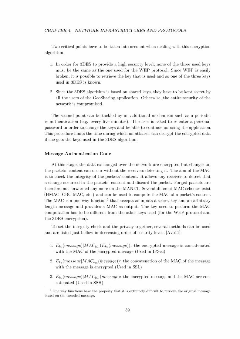
CHAPTER 4. NETWORK INFRASTRUCTURES AND PROTOCOLS
Two critical points have to be taken into account when dealing with this encryption
algorithm.
1. In order for 3DES to provide a high security level, none of the three used keys
must be the same as the one used for the WEP protocol. Since WEP is easily
broken, it is possible to retrieve the key that is used and so one of the three keys
used in 3DES is known.
2. Since the 3DES algorithm is based on shared keys, they have to be kept secret by
all the users of the GeoSharing application. Otherwise, the entire security of the
network is compromised.
The second point can be tackled by an additional mechanism such as a periodic
re-authentication (e.g. every five minutes). The user is asked to re-enter a personal
password in order to change the keys and be able to continue on using the application.
This procedure limits the time during which an attacker can decrypt the encrypted data
if she gets the keys used in the 3DES algorithm.
Message Authentication Code
At this stage, the data exchanged over the network are encrypted but changes on
the packets’ content can occur without the receivers detecting it. The aim of the MAC
is to check the integrity of the packets’ content. It allows any receiver to detect that
a change occurred in the packets’ content and discard the packet. Forged packets are
therefore not forwarded any more on the MANET. Several different MAC schemes exist
(HMAC, CBC-MAC, etc.) and can be used to compute the MAC of a packet’s content.
The MAC is a one way function5 that accepts as inputs a secret key and an arbitrary
length message and provides a MAC as output. The key used to perform the MAC
computation has to be different from the other keys used (for the WEP protocol and
the 3DES encryption).
To set the integrity check and the privacy together, several methods can be used
and are listed just bellow in decreasing order of security levels [Avo11]:
1. Eke(message)|MACkm(Eke(message)): the encrypted message is concatenated
with the MAC of the encrypted message (Used in IPSec)
2. Eke(message|MACkm(message)): the concatenation of the MAC of the message
with the message is encrypted (Used in SSL)
3. Eke(message)|MACkm(message): the encrypted message and the MAC are con-
catenated (Used in SSH)
5 One way functions have the property that it is extremely difficult to retrieve the original messagebased on the encoded message.
39
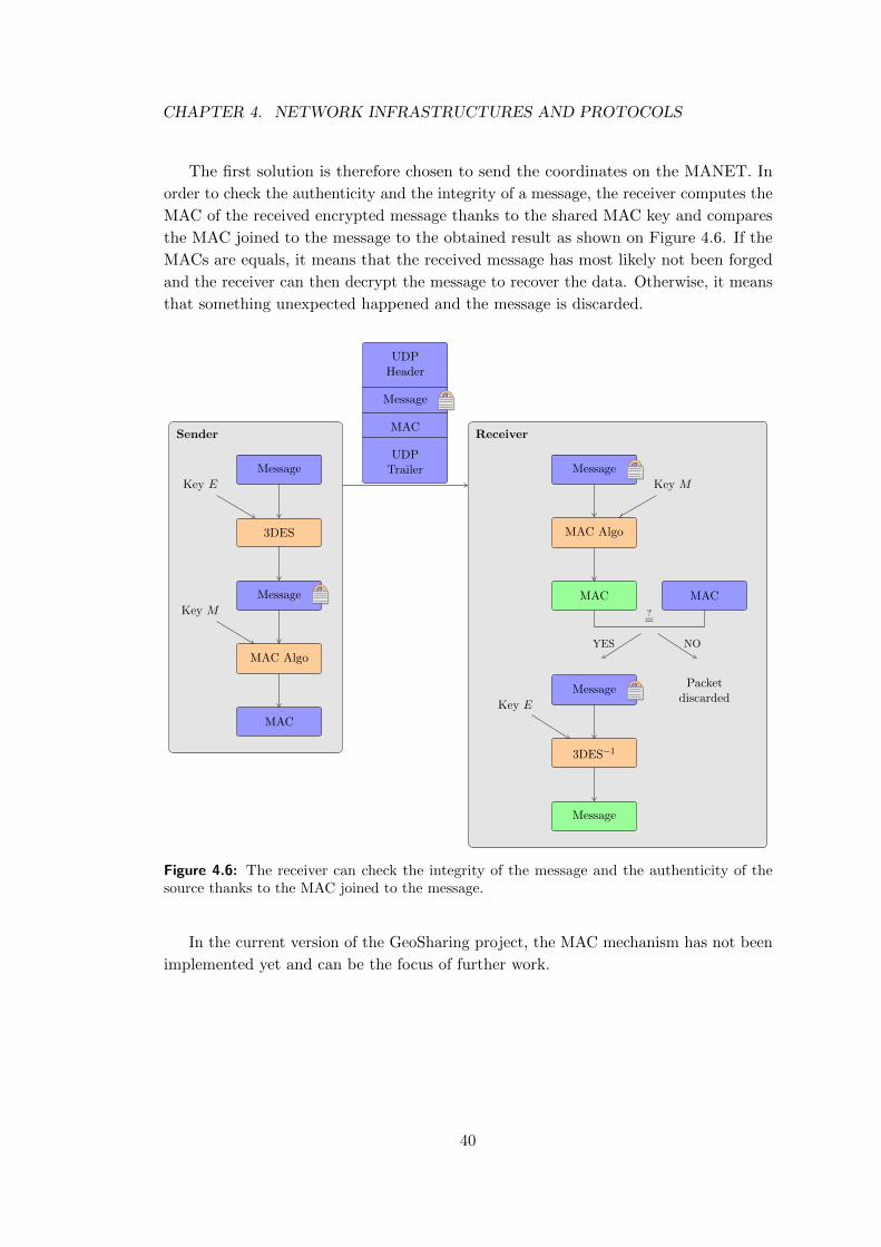
CHAPTER 4. NETWORK INFRASTRUCTURES AND PROTOCOLS
The first solution is therefore chosen to send the coordinates on the MANET. In
order to check the authenticity and the integrity of a message, the receiver computes the
MAC of the received encrypted message thanks to the shared MAC key and compares
the MAC joined to the message to the obtained result as shown on Figure 4.6. If the
MACs are equals, it means that the received message has most likely not been forged
and the receiver can then decrypt the message to recover the data. Otherwise, it means
that something unexpected happened and the message is discarded.
Sender
Message
3DES
Message
MAC Algo
MAC
Key E
Key M
UDPHeader
Message
MAC
UDPTrailer
Receiver
Message
3DES−1
Message
Key E
Message
MAC Algo
MAC MAC
Key M
?=
YES NO
Packetdiscarded
Figure 4.6: The receiver can check the integrity of the message and the authenticity of thesource thanks to the MAC joined to the message.
In the current version of the GeoSharing project, the MAC mechanism has not been
implemented yet and can be the focus of further work.
40
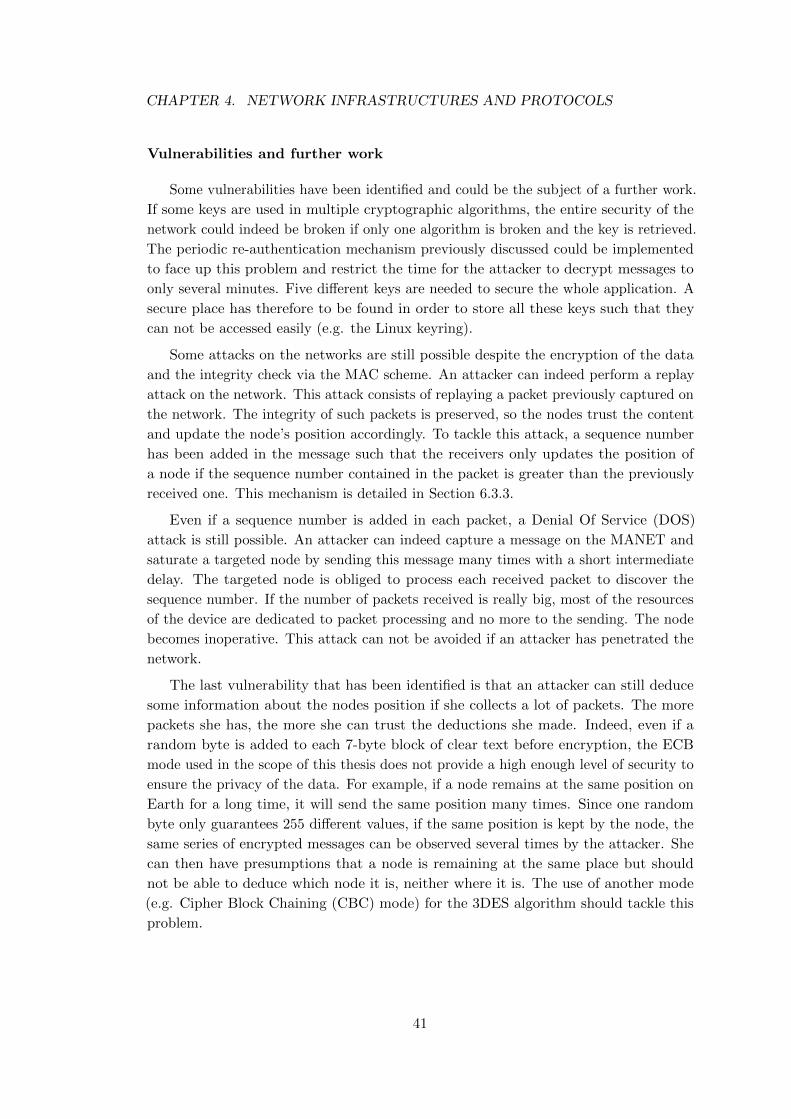
CHAPTER 4. NETWORK INFRASTRUCTURES AND PROTOCOLS
Vulnerabilities and further work
Some vulnerabilities have been identified and could be the subject of a further work.
If some keys are used in multiple cryptographic algorithms, the entire security of the
network could indeed be broken if only one algorithm is broken and the key is retrieved.
The periodic re-authentication mechanism previously discussed could be implemented
to face up this problem and restrict the time for the attacker to decrypt messages to
only several minutes. Five different keys are needed to secure the whole application. A
secure place has therefore to be found in order to store all these keys such that they
can not be accessed easily (e.g. the Linux keyring).
Some attacks on the networks are still possible despite the encryption of the data
and the integrity check via the MAC scheme. An attacker can indeed perform a replay
attack on the network. This attack consists of replaying a packet previously captured on
the network. The integrity of such packets is preserved, so the nodes trust the content
and update the node’s position accordingly. To tackle this attack, a sequence number
has been added in the message such that the receivers only updates the position of
a node if the sequence number contained in the packet is greater than the previously
received one. This mechanism is detailed in Section 6.3.3.
Even if a sequence number is added in each packet, a Denial Of Service (DOS)
attack is still possible. An attacker can indeed capture a message on the MANET and
saturate a targeted node by sending this message many times with a short intermediate
delay. The targeted node is obliged to process each received packet to discover the
sequence number. If the number of packets received is really big, most of the resources
of the device are dedicated to packet processing and no more to the sending. The node
becomes inoperative. This attack can not be avoided if an attacker has penetrated the
network.
The last vulnerability that has been identified is that an attacker can still deduce
some information about the nodes position if she collects a lot of packets. The more
packets she has, the more she can trust the deductions she made. Indeed, even if a
random byte is added to each 7-byte block of clear text before encryption, the ECB
mode used in the scope of this thesis does not provide a high enough level of security to
ensure the privacy of the data. For example, if a node remains at the same position on
Earth for a long time, it will send the same position many times. Since one random
byte only guarantees 255 different values, if the same position is kept by the node, the
same series of encrypted messages can be observed several times by the attacker. She
can then have presumptions that a node is remaining at the same place but should
not be able to deduce which node it is, neither where it is. The use of another mode
(e.g. Cipher Block Chaining (CBC) mode) for the 3DES algorithm should tackle this
problem.
41
CHAPTER 4. NETWORK INFRASTRUCTURES AND PROTOCOLS
4.5 Optimized Link State Routing in GeoSharing
An implementation of the Optimized Link-State Routing has been proposed by
Andreas Tønnesen [Tø04] under the form of a Linux dæmon called OLSRd. This
open-source implementation has been chosen to be part of the GeoSharing project
in order to set up and maintain traffic paths. This dæmon is configured to establish
point-to-point connectivity between all nodes of the MANET but, in GeoSharing, a
multicast address is used to spread GPS coordinates over the network. For this purpose,
a plugin is added to OLSRd.
4.5.1 Optimized Link State Routing Linux dæmon
The Optimized Link State Routing Linux dæmon has been implemented to
be compliant with RFC3626 [CJ03] and can be found on the official web site:
http://www.olsr.org.
Since OLSRd is the routing dæmon used in the GeoSharing MANET, it is relevant
to evaluate the scalability of such a network. The author of this dæmon has run some
tests [OLS07] showing that a very large network composed of thousands of nodes can run
OLSRd without any scalability problem. The mobile devices used in those experiments
were low-cost hardware with small CPU capabilities (200MHz) and 32MB of memory
which is very similar to the devices used in the work of this thesis. The GeoSharing
MANET should therefore not suffer from scalability issues.
4.5.2 Multicast in MANET
An important point to remember about OLSRd is that its goal is to maintain routing
tables up-to-date. Thanks to these tables, a point-to-point connectivity is established
between all nodes. The use of OLSRd permits thus to send data packets from one node
to all other ones by specifying the unique IP address of each node.
In the scope of the GeoSharing project, the use of a multicast address to contact a
group of nodes seems to be mandatory because of the potential high number of nodes
in the network. Furthermore, this technique allows nodes to only receive packets from
group of nodes to which they are attached.
In order to deal correctly with multicast addresses, the Basic Multicast Forwarding
(BMF) plugin is used in addition to OLSRd. This plugin creates a virtual interface
(bmf0) in order to send and receive multicast packets. In practice, only MPRs forward
multicast packets reducing the amount of duplicates with relation to a multicast in a
pure link-state routing protocol.
Section 6.1 presents the way OLSRd and its BMF plugin were installed on Neo
FreeRunner devices used in the scope of this thesis.
42
Chapter 5
Graphical User Interface
From an end-user standpoint, the graphical user interface (GUI) is the most important
component because it is the interface between the user and the application that allows
the user to interact with it to perform the tasks he wants to execute on the application.
This chapter first introduces requirements that must be satisfied by the GUI of the
GeoSharing application. It then describes different ways that can be used to build a
graphical user interface along with the advantages and disadvantages for those different
techniques that can be used. It finally explains the choices that were made for the
GeoSharing application presented in this work.
5.1 Graphical requirements
Building a well designed and clear graphical user interface is always a challenge.
The main purpose of the GUI is to show the geographical positions of other GeoSharing
users on a map. In order to be fully effective, the GUI must satisfy three criteria:
1. usability: the user must feel comfortable with the GUI. Access to the program
functionalities must be easy and intuitive. Each button or each picture in the
GUI must be representative of the action related to them. This means that if a
user sees a button on the interface, he can immediately knows what will happen if
he clicks on it.
2. high performances: the GUI must be reactive and fluid.
3. portability: the interface must be easily ported from one operating system to
another. Portability is close to adaptability in the sense that the GUI must fit
as best as possible the screen resolution of the device running the application.
Just rescaling the GUI to fit another screen resolution is not sufficient. Certain
graphical components which are considered as less important should not appear
on devices with smaller screens.
43
CHAPTER 5. GRAPHICAL USER INTERFACE
5.2 Potential architecture designs
Three possible architecture designs can be used in order to build a graphical user
interface for the GeoSharing application.
1. Stand-alone: one solution to build a graphical user interface is to build it
completely from scratch. Fortunately there exists some well implemented graphical
libraries in C (such as GTK+) which are useful to create windows, buttons, menus,
etc. But the GeoSharing application requires some more complicated features
such as a map service (e.g. Google Maps), a zoom mechanism, a map caching
mechanism for off-line use, etc. The main advantage of this solution is that since
it is build from scratch, every part of the interface will have a role useful for
the application. The main drawback is the cost to develop such an application
regarding already existing libraries.
2. Integrated solution inside an existing application: the second possibility to
develop the interface of the GeoSharing application is to integrate the GeoSharing
functionality into an already developed open-source GPS application. The idea is
to take one stable release of such a GPS application and to add new pieces of code
into it. The advantage of this solution is the simplicity. As in many applications,
the main loop of the program must be found and modified to add the GeoSharing
functionality. One drawback is the backwards and forwards compatibility with
other versions of the concerned GPS application. If the GeoSharing functionality
is directly integrated in the application without anything designed for, users are
obliged to keep this version of the application in which the GeoSharing GUI was
built. Otherwise, GeoSharing updates should be done at the rhythm of the chosen
GPS application which may involve a large maintenance cost.
3. Plugin of an existing application: the third possibility to develop the interface
of the GeoSharing application is, as the second potential choice, to integrate the
GeoSharing functionality into an already developed open-source GPS application.
But the idea, here, is to first extend the GPS application to be plugin compliant
and provide a simple interface for any plugin to interact with this GPS application.
The next step is to develop one plugin for the GeoSharing functionality. The
main advantage is the compatibility with any newer version of the concerned GPS
application. If the core modifications in the GPS application (allowing people
to add plugins) are as general as possible and are accepted by the developers
community, these modifications will indeed remain on all new versions. In the same
way, the GeoSharing specific plugin will remain compatible with the determined
interface and the entire application will run correctly. One drawback is the weight
of the final application. People who want to use GeoSharing must install this
plugin compliant GPS application and the GeoSharing plugin.
44
CHAPTER 5. GRAPHICAL USER INTERFACE
5.3 Choice of the architecture design
As just explained, the three possible architecture designs present pros and cons. In
a first time, the choice to discard the first solution (i.e. developing everything from
scratch) was made to focus on the functionalities of the GeoSharing application and
to have a usable user interface while minimizing the development cost. The developed
interface could so be quickly used and could eventually be developed from scratch in
future versions for efficiency, memory and CPU usage reasons.
Among the two remaining choices, the solution based on the plugin, proving the
greatest modularity, is preferred. Adding the GeoSharing functionality into the core
methods of an existing GPS application (i.e. solution number two) implies a decrease of
the overall application cohesion1 with an increase of its coupling2 which is contrary to
general rules of software engineering. That observation motivated the choice done for
the GeoSharing application.
There are different possible choices for the application on which to develop the
GeoSharing plugin. The default GPS application proposed with SHR (which is the
operating system chosen to be part of the GeoSharing project) is tangoGPS. Another
possible GPS application for Linux-based systems is Navit. The choice made in this work
is to develop a GeoSharing plugin for tangoGPS. According to the criteria described in
Section 5.1, it is obvious that tangoGPS is more suitable for the GeoSharing project.
It indeed appears that Navit is more complicated to handle because menus are less
intuitive and clear. The integration of a plugin menu in this existing menu is therefore
complicated. The usability of Navit is thus worst than the usability of tangoGPS. Navit
also offers lots of functionalities which are useless in the scope of the GeoSharing project
such as car navigation instructions, shortest path computation, etc. From a performance
standpoint, Navit and tangoGPS are equivalent. Since both applications provide a
mobile and a desktop version, the portability criterion is, as well as the performance
criterion, useless to choose between Navit and tangoGPS. Only the usability criterion
leads to the choice in favour of tangoGPS.
5.4 TangoGPS plugin in details
It was necessary to adapt the standard tangoGPS version to be plugin compliant.
For this purpose, a plugins interface has been developed and is presented in the first
part of this section. The second part summarizes the requirements that need to be
fulfilled in order to create a new plugin for tangoGPS.
1 “In computer programming, cohesion is a measure of how strongly-related the functionality expressedby the source code of a software module is” [Coh11].
2 “In computer science, coupling or dependency is the degree to which each program module relies oneach one of the other modules” [Cou11].
45
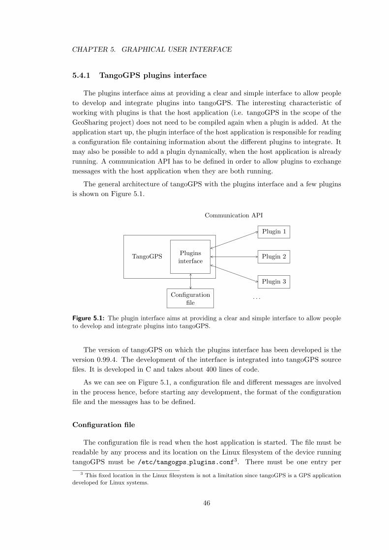
CHAPTER 5. GRAPHICAL USER INTERFACE
5.4.1 TangoGPS plugins interface
The plugins interface aims at providing a clear and simple interface to allow people
to develop and integrate plugins into tangoGPS. The interesting characteristic of
working with plugins is that the host application (i.e. tangoGPS in the scope of the
GeoSharing project) does not need to be compiled again when a plugin is added. At the
application start up, the plugin interface of the host application is responsible for reading
a configuration file containing information about the different plugins to integrate. It
may also be possible to add a plugin dynamically, when the host application is already
running. A communication API has to be defined in order to allow plugins to exchange
messages with the host application when they are both running.
The general architecture of tangoGPS with the plugins interface and a few plugins
is shown on Figure 5.1.
TangoGPSPluginsinterface
Configurationfile
Plugin 1
Plugin 2
Plugin 3
. . .
Communication API
Figure 5.1: The plugin interface aims at providing a clear and simple interface to allow peopleto develop and integrate plugins into tangoGPS.
The version of tangoGPS on which the plugins interface has been developed is the
version 0.99.4. The development of the interface is integrated into tangoGPS source
files. It is developed in C and takes about 400 lines of code.
As we can see on Figure 5.1, a configuration file and different messages are involved
in the process hence, before starting any development, the format of the configuration
file and the messages has to be defined.
Configuration file
The configuration file is read when the host application is started. The file must be
readable by any process and its location on the Linux filesystem of the device running
tangoGPS must be /etc/tangogps plugins.conf3. There must be one entry per
3 This fixed location in the Linux filesystem is not a limitation since tangoGPS is a GPS applicationdeveloped for Linux systems.
46
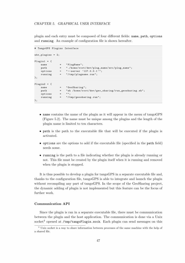
CHAPTER 5. GRAPHICAL USER INTERFACE
plugin and each entry must be composed of four different fields: name, path, options
and running. An example of configuration file is shown hereafter.
# TangoGPS Plugins Interface
nbr_plugins = 2;
Plugin1 = {
name = "PlugName";
path = "./home/root/dev/plug_name/src/plug_name";
options = "--server ’127.0.0.1 ’";
running = "/tmp/plugname.run";
};
Plugin2 = {
name = "GeoSharing";
path = "sh /home/root/dev/geo_sharing/run_geosharing.sh";
options = "";
running = "/tmp/geosharing.run";
};
• name contains the name of the plugin as it will appear in the menu of tangoGPS
(Figure 5.2). The name must be unique among the plugins and the length of the
plugin name is limited to ten characters.
• path is the path to the executable file that will be executed if the plugin is
activated.
• options are the options to add if the executable file (specified in the path field)
needs some.
• running is the path to a file indicating whether the plugin is already running or
not. This file must be created by the plugin itself when it is running and removed
when the plugin is stopped.
It is thus possible to develop a plugin for tangoGPS in a separate executable file and,
thanks to the configuration file, tangoGPS is able to integrate and launch the plugin
without recompiling any part of tangoGPS. In the scope of the GeoSharing project,
the dynamic adding of plugin is not implemented but this feature can be the focus of
further work.
Communication API
Since the plugin is ran in a separate executable file, there must be communication
between the plugin and the host application. The communication is done via a Unix
socket4 opened at /tmp/tangoPlugin.sock. Each plugin can send messages on this
4 Unix socket is a way to share information between processes of the same machine with the help ofa shared file.
47
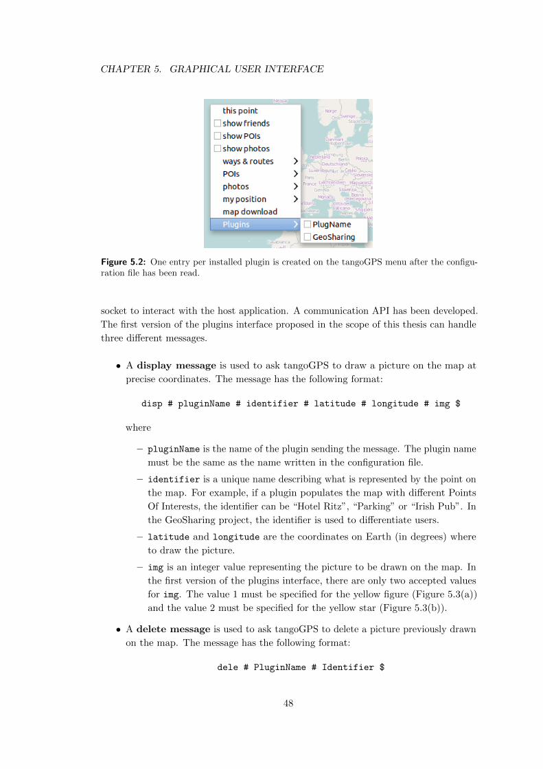
CHAPTER 5. GRAPHICAL USER INTERFACE
Figure 5.2: One entry per installed plugin is created on the tangoGPS menu after the configu-ration file has been read.
socket to interact with the host application. A communication API has been developed.
The first version of the plugins interface proposed in the scope of this thesis can handle
three different messages.
• A display message is used to ask tangoGPS to draw a picture on the map at
precise coordinates. The message has the following format:
disp # pluginName # identifier # latitude # longitude # img $
where
– pluginName is the name of the plugin sending the message. The plugin name
must be the same as the name written in the configuration file.
– identifier is a unique name describing what is represented by the point on
the map. For example, if a plugin populates the map with different Points
Of Interests, the identifier can be “Hotel Ritz”, “Parking” or “Irish Pub”. In
the GeoSharing project, the identifier is used to differentiate users.
– latitude and longitude are the coordinates on Earth (in degrees) where
to draw the picture.
– img is an integer value representing the picture to be drawn on the map. In
the first version of the plugins interface, there are only two accepted values
for img. The value 1 must be specified for the yellow figure (Figure 5.3(a))
and the value 2 must be specified for the yellow star (Figure 5.3(b)).
• A delete message is used to ask tangoGPS to delete a picture previously drawn
on the map. The message has the following format:
dele # PluginName # Identifier $
48
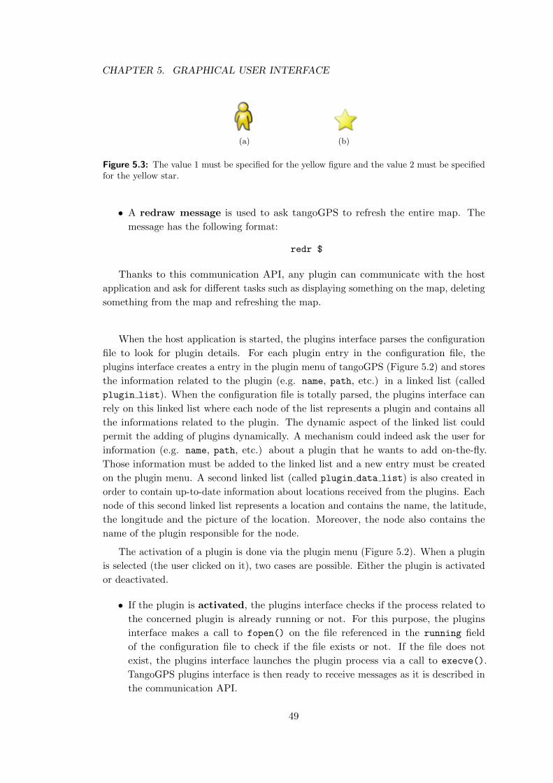
CHAPTER 5. GRAPHICAL USER INTERFACE
(a) (b)
Figure 5.3: The value 1 must be specified for the yellow figure and the value 2 must be specifiedfor the yellow star.
• A redraw message is used to ask tangoGPS to refresh the entire map. The
message has the following format:
redr $
Thanks to this communication API, any plugin can communicate with the host
application and ask for different tasks such as displaying something on the map, deleting
something from the map and refreshing the map.
When the host application is started, the plugins interface parses the configuration
file to look for plugin details. For each plugin entry in the configuration file, the
plugins interface creates a entry in the plugin menu of tangoGPS (Figure 5.2) and stores
the information related to the plugin (e.g. name, path, etc.) in a linked list (called
plugin list). When the configuration file is totally parsed, the plugins interface can
rely on this linked list where each node of the list represents a plugin and contains all
the informations related to the plugin. The dynamic aspect of the linked list could
permit the adding of plugins dynamically. A mechanism could indeed ask the user for
information (e.g. name, path, etc.) about a plugin that he wants to add on-the-fly.
Those information must be added to the linked list and a new entry must be created
on the plugin menu. A second linked list (called plugin data list) is also created in
order to contain up-to-date information about locations received from the plugins. Each
node of this second linked list represents a location and contains the name, the latitude,
the longitude and the picture of the location. Moreover, the node also contains the
name of the plugin responsible for the node.
The activation of a plugin is done via the plugin menu (Figure 5.2). When a plugin
is selected (the user clicked on it), two cases are possible. Either the plugin is activated
or deactivated.
• If the plugin is activated, the plugins interface checks if the process related to
the concerned plugin is already running or not. For this purpose, the plugins
interface makes a call to fopen() on the file referenced in the running field
of the configuration file to check if the file exists or not. If the file does not
exist, the plugins interface launches the plugin process via a call to execve().
TangoGPS plugins interface is then ready to receive messages as it is described in
the communication API.
49
CHAPTER 5. GRAPHICAL USER INTERFACE
• If the plugin is deactivated, every location for which the plugin is responsible
has to be removed from the screen and from the plugin data list.
Upon reception of a message on the Unix socket of the plugins interface, the message
must be processed. The plugins interface takes the first four characters of the message
to extract the type of the message. It can be disp, dele or redr.
1. If it is disp, the plugins interface checks if the plugin which sent the message is
active or. If it is the case, the plugins interface updates the plugin data list
with the information contained in the message.
2. If it is dele, the plugins interface also checks if the plugin which sent the message
is active or not. If it is the case, the plugins interface deletes the location specified
in the message from the plugin data list.
3. If it is redr, the plugins interface calls repaint all() which is an already im-
plemented function of tangoGPS. The repaint all() function is responsible for
repainting the entire map including locations received from the plugins.
5.4.2 Plugin creation
The creation of a new plugin for tangoGPS is made easier with the plugins interface.
Thanks to the configuration file, any plugin can be added to tangoGPS without the need
of compiling again the whole application. The new plugin is developed independently of
tangoGPS. There are only a very few requirements that must be satisfied by the new
plugin.
1. The new plugin must be compiled and the binary file must be made available for
tangoGPS.
2. The configuration file of tangoGPS plugins interface must be filled in correctly
with all the information needed to launch the plugin.
3. All the messages sent to the plugins interface must respect the communication API.
Apart from that, the new plugin can implement any functionality while the format
of the interactions with the plugins interface remains compliant with what is defined in
Section 5.4.1.
The modifications made to tangoGPS in order to make it plugin compliant allow
anyone to add new functionalities to tangoGPS with a small development cost. Many
functionalities can now easily be ported to tangoGPS. For example, a new plugin can
be developed to display to a car user all the radar systems whose locations are stored in
a database.
50
Chapter 6
GeoSharing project
This chapter is dedicated to the practical steps which led to the GeoSharing appli-
cation. The theoretical choices made during the elaboration of the GeoSharing project
have been incrementally implemented and integrated to form a whole. The C language
has been chosen to implement the different functionalities of GeoSharing mainly for
its high performances that makes it suitable for application development running on
low-cost hardware. Moreover, the C language is widespread in mobile application
development hence a C compiler (e.g. gcc) is available for many architectures either
directly in the operating system running on the device or as a cross-compiler.
The first section of this chapter presents how the Linux OLSR dæmon has been
integrated to the GeoSharing project to serve the GeoSharing objectives in terms of
network topology management. The second section explains the way all the different
parts of the GeoSharing project run together. Section 6.3 details the core functionalities
of the GeoSharing application and how those functionalities are implemented. Section 6.4
explains how to enjoy the GeoSharing application as an end-user. Finally, Section 6.5
presents future development work that can be done to improve the GeoSharing project
and bring it further.
6.1 OLSRd and BMF set up on the Neo FreeRunner
As stated in Section 4.5, the OLSRd dæmon developed by Andreas Tønnesen [Tø04]
was chosen to be part of the GeoSharing project. This dæmon provides efficient
routing table management and low forwarding delays. In addition to this dæmon, the
BMF plugin is used to allow multicast packet forwarding required in the scope of the
GeoSharing application.
The source code of the 0.6.0 version of OLSRd is available on http://www.olsr.org,
the official website of OLSRd dæmon. The sources must be compiled for the Openmoko
specific architecture. This OLSR dæmon contains a syntactical analyser (for exchanged
messages analysis purpose) whose source code must be generated before the dæmon
51
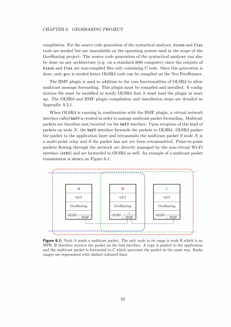
CHAPTER 6. GEOSHARING PROJECT
compilation. For the source code generation of the syntactical analyser, bison and flex
tools are needed but are unavailable on the operating system used in the scope of the
GeoSharing project. The source code generation of the syntactical analyser can also
be done on any architecture (e.g. on a standard i686 computer) since the outputs of
bison and flex are non-compiled files only containing C code. Once this generation is
done, only gcc is needed hence OLSRd code can be compiled on the Neo FreeRunner.
The BMF plugin is used in addition to the core functionalities of OLSRd to allow
multicast message forwarding. This plugin must be compiled and installed. A config-
uration file must be modified to notify OLSRd that it must load the plugin at start
up. The OLSRd and BMF plugin compilation and installation steps are detailed in
Appendix A.2.1.
When OLSRd is running in combination with the BMF plugin, a virtual network
interface called bmf0 is created in order to manage multicast packet forwarding. Multicast
packets are therefore sent/received via the bmf0 interface. Upon reception of this kind of
packets on node N , the bmf0 interface forwards the packets to OLSRd. OLSRd pushes
the packet to the application layer and retransmits the multicast packet if node N is
a multi-point relay and if the packet has not yet been retransmitted. Point-to-point
packets flowing through the network are directly managed by the non-virtual Wi-Fi
interface (eth0) and are forwarded to OLSRd as well. An example of a multicast packet
transmission is shown on Figure 6.1.
A
GUI
GeoSharing
OLRSBMF
B
GUI
GeoSharing
OLRSBMF
C
GUI
GeoSharing
OLRSBMF
Figure 6.1: Node A sends a multicast packet. The only node in its range is node B which is anMPR. B therefore receives the packet on the bmf interface. A copy is pushed to the applicationand the multicast packet is forwarded to C which processes the packet in the same way. Radioranges are represented with dashed coloured lines.
52
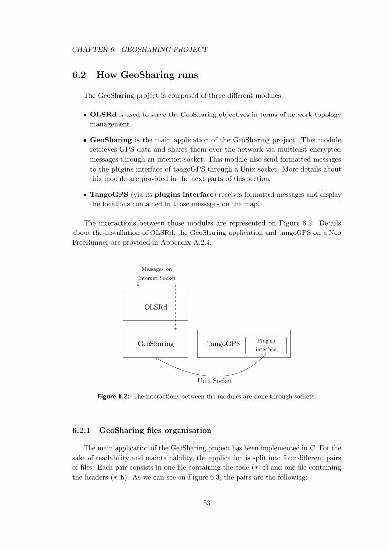
CHAPTER 6. GEOSHARING PROJECT
6.2 How GeoSharing runs
The GeoSharing project is composed of three different modules.
• OLSRd is used to serve the GeoSharing objectives in terms of network topology
management.
• GeoSharing is the main application of the GeoSharing project. This module
retrieves GPS data and shares them over the network via multicast encrypted
messages through an internet socket. This module also send formatted messages
to the plugins interface of tangoGPS through a Unix socket. More details about
this module are provided in the next parts of this section.
• TangoGPS (via its plugins interface) receives formatted messages and display
the locations contained in those messages on the map.
The interactions between those modules are represented on Figure 6.2. Details
about the installation of OLSRd, the GeoSharing application and tangoGPS on a Neo
FreeRunner are provided in Appendix A.2.4.
GeoSharing TangoGPS Plugins
interface
Unix Socket
OLSRd
Messages on
Internet Socket
Figure 6.2: The interactions between the modules are done through sockets.
6.2.1 GeoSharing files organisation
The main application of the GeoSharing project has been implemented in C. For the
sake of readability and maintainability, the application is split into four different pairs
of files. Each pair consists in one file containing the code (*.c) and one file containing
the headers (*.h). As we can see on Figure 6.3, the pairs are the following:
53
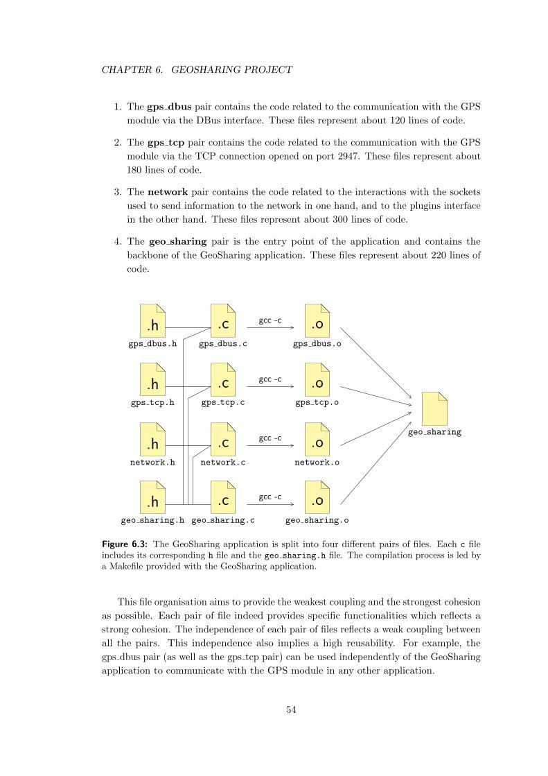
CHAPTER 6. GEOSHARING PROJECT
1. The gps dbus pair contains the code related to the communication with the GPS
module via the DBus interface. These files represent about 120 lines of code.
2. The gps tcp pair contains the code related to the communication with the GPS
module via the TCP connection opened on port 2947. These files represent about
180 lines of code.
3. The network pair contains the code related to the interactions with the sockets
used to send information to the network in one hand, and to the plugins interface
in the other hand. These files represent about 300 lines of code.
4. The geo sharing pair is the entry point of the application and contains the
backbone of the GeoSharing application. These files represent about 220 lines of
code.
geo sharing
.hgps dbus.h
.cgps dbus.c
.ogps dbus.o
gcc -c
.hgps tcp.h
.cgps tcp.c
.ogps tcp.o
gcc -c
.hnetwork.h
.cnetwork.c
.onetwork.o
gcc -c
.hgeo sharing.h
.cgeo sharing.c
.ogeo sharing.o
gcc -c
Figure 6.3: The GeoSharing application is split into four different pairs of files. Each c fileincludes its corresponding h file and the geo sharing.h file. The compilation process is led bya Makefile provided with the GeoSharing application.
This file organisation aims to provide the weakest coupling and the strongest cohesion
as possible. Each pair of file indeed provides specific functionalities which reflects a
strong cohesion. The independence of each pair of files reflects a weak coupling between
all the pairs. This independence also implies a high reusability. For example, the
gps dbus pair (as well as the gps tcp pair) can be used independently of the GeoSharing
application to communicate with the GPS module in any other application.
54
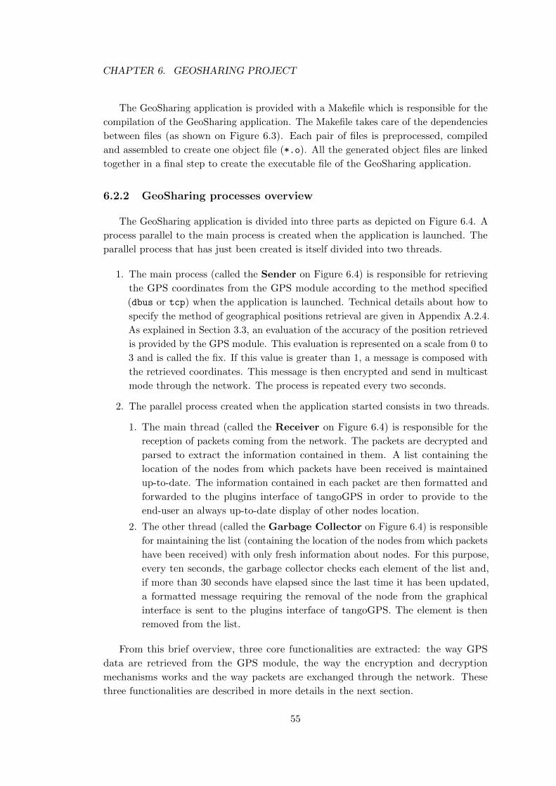
CHAPTER 6. GEOSHARING PROJECT
The GeoSharing application is provided with a Makefile which is responsible for the
compilation of the GeoSharing application. The Makefile takes care of the dependencies
between files (as shown on Figure 6.3). Each pair of files is preprocessed, compiled
and assembled to create one object file (*.o). All the generated object files are linked
together in a final step to create the executable file of the GeoSharing application.
6.2.2 GeoSharing processes overview
The GeoSharing application is divided into three parts as depicted on Figure 6.4. A
process parallel to the main process is created when the application is launched. The
parallel process that has just been created is itself divided into two threads.
1. The main process (called the Sender on Figure 6.4) is responsible for retrieving
the GPS coordinates from the GPS module according to the method specified
(dbus or tcp) when the application is launched. Technical details about how to
specify the method of geographical positions retrieval are given in Appendix A.2.4.
As explained in Section 3.3, an evaluation of the accuracy of the position retrieved
is provided by the GPS module. This evaluation is represented on a scale from 0 to
3 and is called the fix. If this value is greater than 1, a message is composed with
the retrieved coordinates. This message is then encrypted and send in multicast
mode through the network. The process is repeated every two seconds.
2. The parallel process created when the application started consists in two threads.
1. The main thread (called the Receiver on Figure 6.4) is responsible for the
reception of packets coming from the network. The packets are decrypted and
parsed to extract the information contained in them. A list containing the
location of the nodes from which packets have been received is maintained
up-to-date. The information contained in each packet are then formatted and
forwarded to the plugins interface of tangoGPS in order to provide to the
end-user an always up-to-date display of other nodes location.
2. The other thread (called the Garbage Collector on Figure 6.4) is responsible
for maintaining the list (containing the location of the nodes from which packets
have been received) with only fresh information about nodes. For this purpose,
every ten seconds, the garbage collector checks each element of the list and,
if more than 30 seconds have elapsed since the last time it has been updated,
a formatted message requiring the removal of the node from the graphical
interface is sent to the plugins interface of tangoGPS. The element is then
removed from the list.
From this brief overview, three core functionalities are extracted: the way GPS
data are retrieved from the GPS module, the way the encryption and decryption
mechanisms works and the way packets are exchanged through the network. These
three functionalities are described in more details in the next section.
55
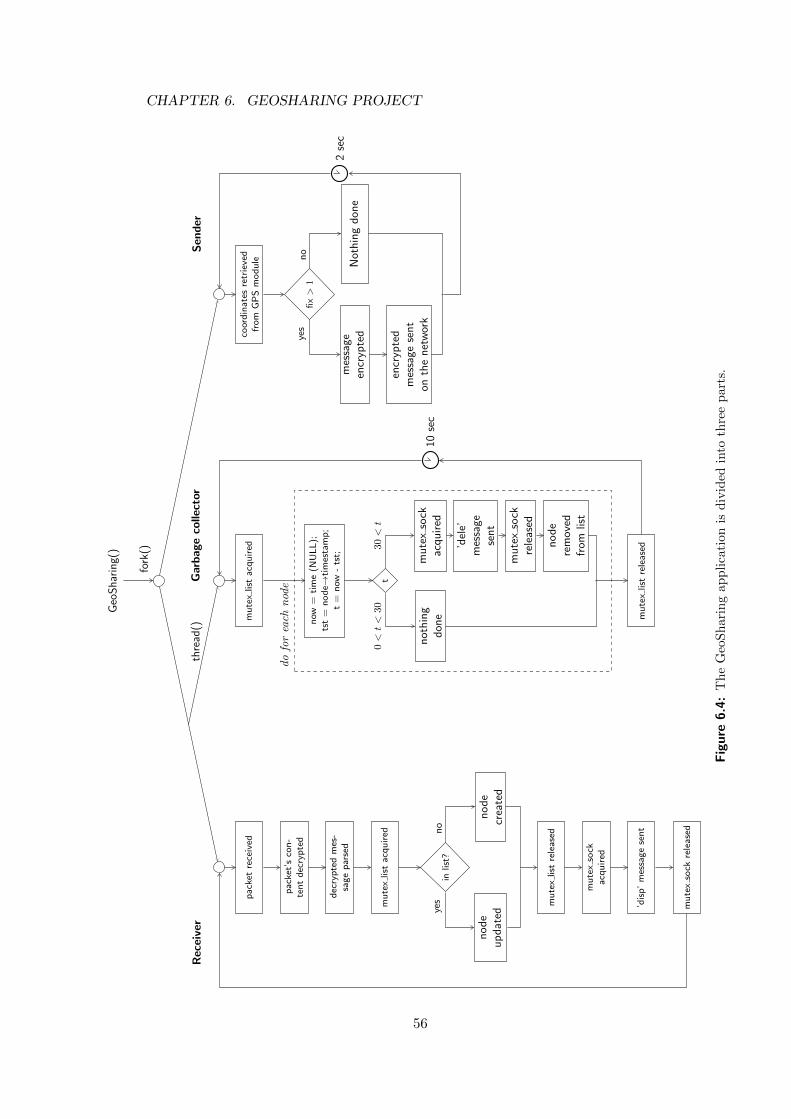
CHAPTER 6. GEOSHARING PROJECTG
eoS
har
ing(
)
fork
()
Rec
eive
r
pac
ket
rece
ived
pac
ket’
sco
n-
ten
td
ecry
pte
d
dec
ryp
ted
mes
-sa
ge
par
sed
mu
tex
list
acq
uir
ed
inlis
t?
no
de
up
dat
edn
od
ecr
eate
d
mu
tex
list
rele
ased
mu
tex
sock
acq
uir
ed
’dis
p’
mes
sag
ese
nt
mu
tex
sock
rele
ased
yes
no
Garbageco
llector
mu
tex
list
acq
uir
ed
now
=ti
me
(NU
LL
);ts
t=
no
de→
tim
esta
mp
;t
=n
ow-
tst;
t
no
thin
gd
on
e
mu
tex
sock
acq
uir
ed
’del
e’m
essa
ge
sen
t
mu
tex
sock
rele
ased
no
de
rem
ove
dfr
om
list
mu
tex
list
rele
ased
10se
c
do
for
each
nod
e
0<
t<
3030
<t
Sen
der
coor
din
ates
retr
ieve
dfr
om
GP
Sm
od
ule
fix>
1
mes
sag
een
cryp
ted
encr
ypte
dm
essa
ge
sen
to
nth
en
etw
ork
No
thin
gd
on
e2
sec
yes
no
thre
ad()
Figure
6.4:
Th
eG
eoS
hari
ng
ap
pli
cati
on
isd
ivid
edin
toth
ree
part
s.
56
CHAPTER 6. GEOSHARING PROJECT
6.3 GeoSharing core functionalities
The GeoSharing application consists in different core functionalities. Geographical
coordinates must be retrieved from the GPS module. Once these coordinates are
available, a secured data packet must be build to be sent through the network. Upon
reception of a data packet from another node, the coordinates must be made available
to the GUI.
6.3.1 Location data retrieval
In order to retrieve location data, a communication must be established between
the GeoSharing application and the GPS module. As stated in Chapter 3, two different
ways to communicate with the GPS module have been implemented in GeoSharing:
D-Bus and TCP communication scheme. Both solutions are usable in GeoSharing (see
Appendix A.2.4) but the D-Bus solution is used by default.
• D-Bus: The geo-position data retrieval consists in three steps. The first two steps
initialise the D-Bus connection and the GPS module.
1. The connection on the bus is made via a call to dbus g bus get() of the
DBusGLib library [DBu07]. The bus type towards which the connection
should be done must be specified and the call returns a connection to this
bus.
DBusGConnection *connection = NULL;
GError *error = NULL;
connection = dbus_g_bus_get(DBUS_BUS_SYSTEM , &error);
Listing 6.1: This piece of C code is taken from gps dbus.c.
where
– DBUS BUS SYSTEM is a constant from the DBusGLib library specifying
the bus on which the connection has to be established;
– error is an address where an error can be returned.
2. The start of the GPS module is made via a call to dbus g proxy call().
This function takes a method name as argument. To start the GPS module,
"Start" must be specified as method name. There is no returned value of
this call.
57
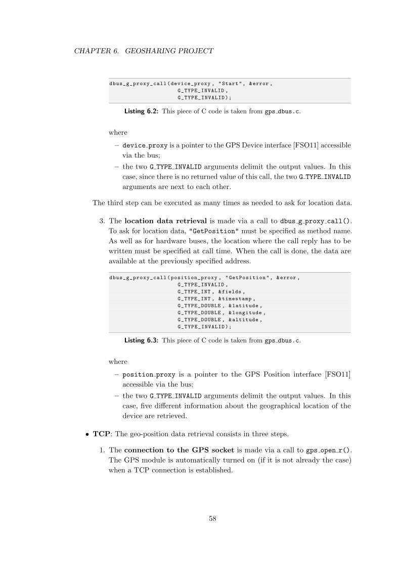
CHAPTER 6. GEOSHARING PROJECT
dbus_g_proxy_call(device_proxy , "Start", &error ,
G_TYPE_INVALID ,
G_TYPE_INVALID);
Listing 6.2: This piece of C code is taken from gps dbus.c.
where
– device proxy is a pointer to the GPS Device interface [FSO11] accessible
via the bus;
– the two G TYPE INVALID arguments delimit the output values. In this
case, since there is no returned value of this call, the two G TYPE INVALID
arguments are next to each other.
The third step can be executed as many times as needed to ask for location data.
3. The location data retrieval is made via a call to dbus g proxy call().
To ask for location data, "GetPosition" must be specified as method name.
As well as for hardware buses, the location where the call reply has to be
written must be specified at call time. When the call is done, the data are
available at the previously specified address.
dbus_g_proxy_call(position_proxy , "GetPosition", &error ,
G_TYPE_INVALID ,
G_TYPE_INT , &fields ,
G_TYPE_INT , ×tamp ,
G_TYPE_DOUBLE , &latitude ,
G_TYPE_DOUBLE , &longitude ,
G_TYPE_DOUBLE , &altitude ,
G_TYPE_INVALID);
Listing 6.3: This piece of C code is taken from gps dbus.c.
where
– position proxy is a pointer to the GPS Position interface [FSO11]
accessible via the bus;
– the two G TYPE INVALID arguments delimit the output values. In this
case, five different information about the geographical location of the
device are retrieved.
• TCP: The geo-position data retrieval consists in three steps.
1. The connection to the GPS socket is made via a call to gps open r().
The GPS module is automatically turned on (if it is not already the case)
when a TCP connection is established.
58
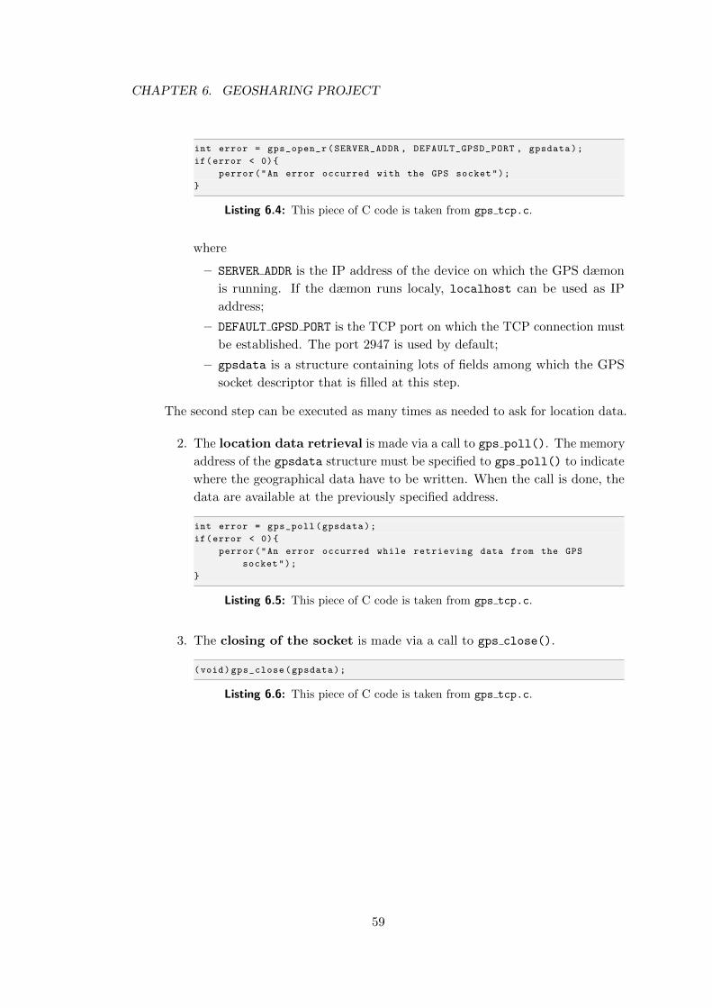
CHAPTER 6. GEOSHARING PROJECT
int error = gps_open_r(SERVER_ADDR , DEFAULT_GPSD_PORT , gpsdata);
if(error < 0){
perror("An error occurred with the GPS socket");
}
Listing 6.4: This piece of C code is taken from gps tcp.c.
where
– SERVER ADDR is the IP address of the device on which the GPS dæmon
is running. If the dæmon runs localy, localhost can be used as IP
address;
– DEFAULT GPSD PORT is the TCP port on which the TCP connection must
be established. The port 2947 is used by default;
– gpsdata is a structure containing lots of fields among which the GPS
socket descriptor that is filled at this step.
The second step can be executed as many times as needed to ask for location data.
2. The location data retrieval is made via a call to gps poll(). The memory
address of the gpsdata structure must be specified to gps poll() to indicate
where the geographical data have to be written. When the call is done, the
data are available at the previously specified address.
int error = gps_poll(gpsdata);
if(error < 0){
perror("An error occurred while retrieving data from the GPS
socket");
}
Listing 6.5: This piece of C code is taken from gps tcp.c.
3. The closing of the socket is made via a call to gps close().
(void)gps_close(gpsdata);
Listing 6.6: This piece of C code is taken from gps tcp.c.
59
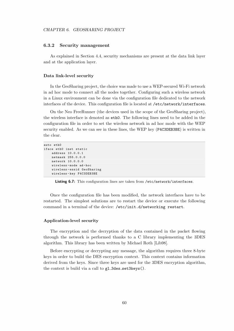
CHAPTER 6. GEOSHARING PROJECT
6.3.2 Security management
As explained in Section 4.4, security mechanisms are present at the data link layer
and at the application layer.
Data link-level security
In the GeoSharing project, the choice was made to use a WEP-secured Wi-Fi network
in ad hoc mode to connect all the nodes together. Configuring such a wireless network
in a Linux environment can be done via the configuration file dedicated to the network
interfaces of the device. This configuration file is located at /etc/network/interfaces.
On the Neo FreeRunner (the devices used in the scope of the GeoSharing project),
the wireless interface is denoted as eth0. The following lines need to be added in the
configuration file in order to set the wireless network in ad hoc mode with the WEP
security enabled. As we can see in these lines, the WEP key (F4C3DEB3BE) is written in
the clear.
auto eth0
iface eth0 inet static
address 10.0.0.1
netmask 255.0.0.0
network 10.0.0.0
wireless -mode ad -hoc
wireless -essid GeoSharing
wireless -key F4C3DEB3BE
Listing 6.7: This configuration lines are taken from /etc/network/interfaces.
Once the configuration file has been modified, the network interfaces have to be
restarted. The simplest solutions are to restart the device or execute the following
command in a terminal of the device: /etc/init.d/networking restart.
Application-level security
The encryption and the decryption of the data contained in the packet flowing
through the network is performed thanks to a C library implementing the 3DES
algorithm. This library has been written by Michael Roth [Lib98].
Before encrypting or decrypting any message, the algorithm requires three 8-byte
keys in order to build the DES encryption context. This context contains information
derived from the keys. Since three keys are used for the 3DES encryption algorithm,
the context is build via a call to gl 3des set3keys().
60
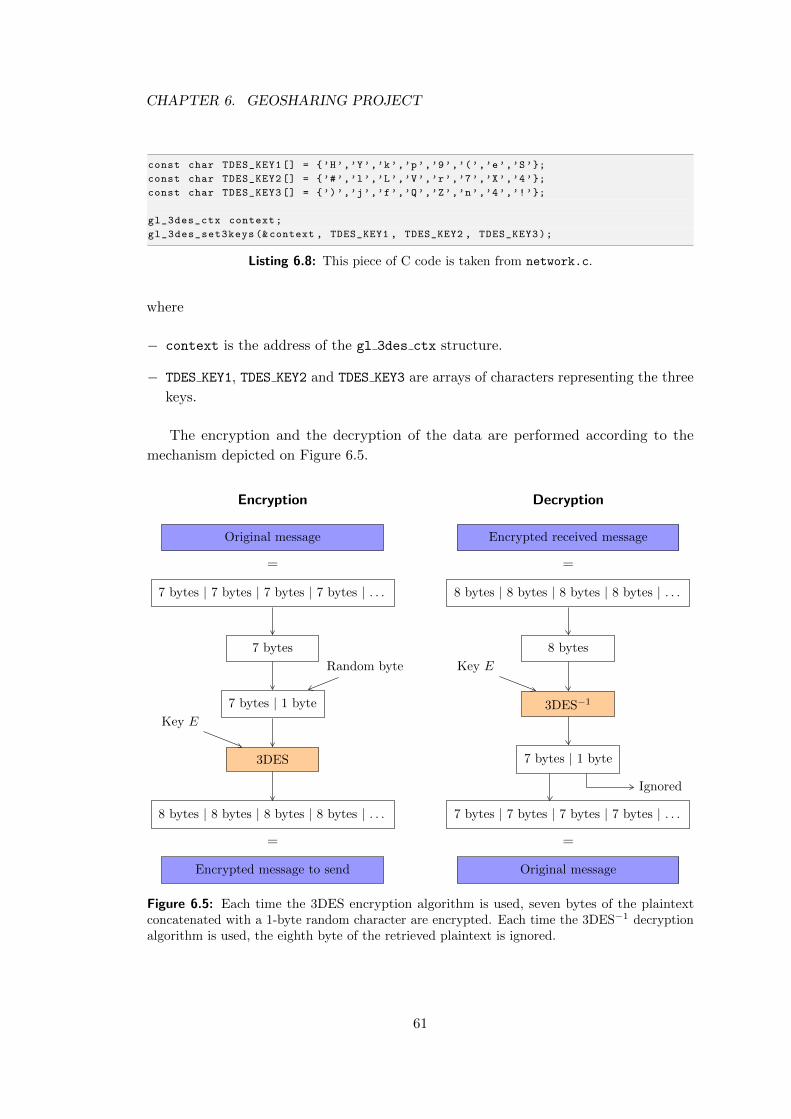
CHAPTER 6. GEOSHARING PROJECT
const char TDES_KEY1 [] = {’H’,’Y’,’k’,’p’,’9’,’(’,’e’,’S’};
const char TDES_KEY2 [] = {’#’,’l’,’L’,’V’,’r’,’7’,’X’,’4’};
const char TDES_KEY3 [] = {’)’,’j’,’f’,’Q’,’Z’,’n’,’4’,’!’};
gl_3des_ctx context;
gl_3des_set3keys (&context , TDES_KEY1 , TDES_KEY2 , TDES_KEY3);
Listing 6.8: This piece of C code is taken from network.c.
where
− context is the address of the gl 3des ctx structure.
− TDES KEY1, TDES KEY2 and TDES KEY3 are arrays of characters representing the three
keys.
The encryption and the decryption of the data are performed according to the
mechanism depicted on Figure 6.5.
Encryption
Original message
=
7 bytes | 7 bytes | 7 bytes | 7 bytes | . . .
7 bytes
7 bytes | 1 byte
Random byte
3DES
Key E
8 bytes | 8 bytes | 8 bytes | 8 bytes | . . .
=
Encrypted message to send
Decryption
Encrypted received message
=
8 bytes | 8 bytes | 8 bytes | 8 bytes | . . .
8 bytes
3DES−1
Key E
7 bytes | 1 byte
Ignored
7 bytes | 7 bytes | 7 bytes | 7 bytes | . . .
=
Original message
Figure 6.5: Each time the 3DES encryption algorithm is used, seven bytes of the plaintextconcatenated with a 1-byte random character are encrypted. Each time the 3DES−1 decryptionalgorithm is used, the eighth byte of the retrieved plaintext is ignored.
61
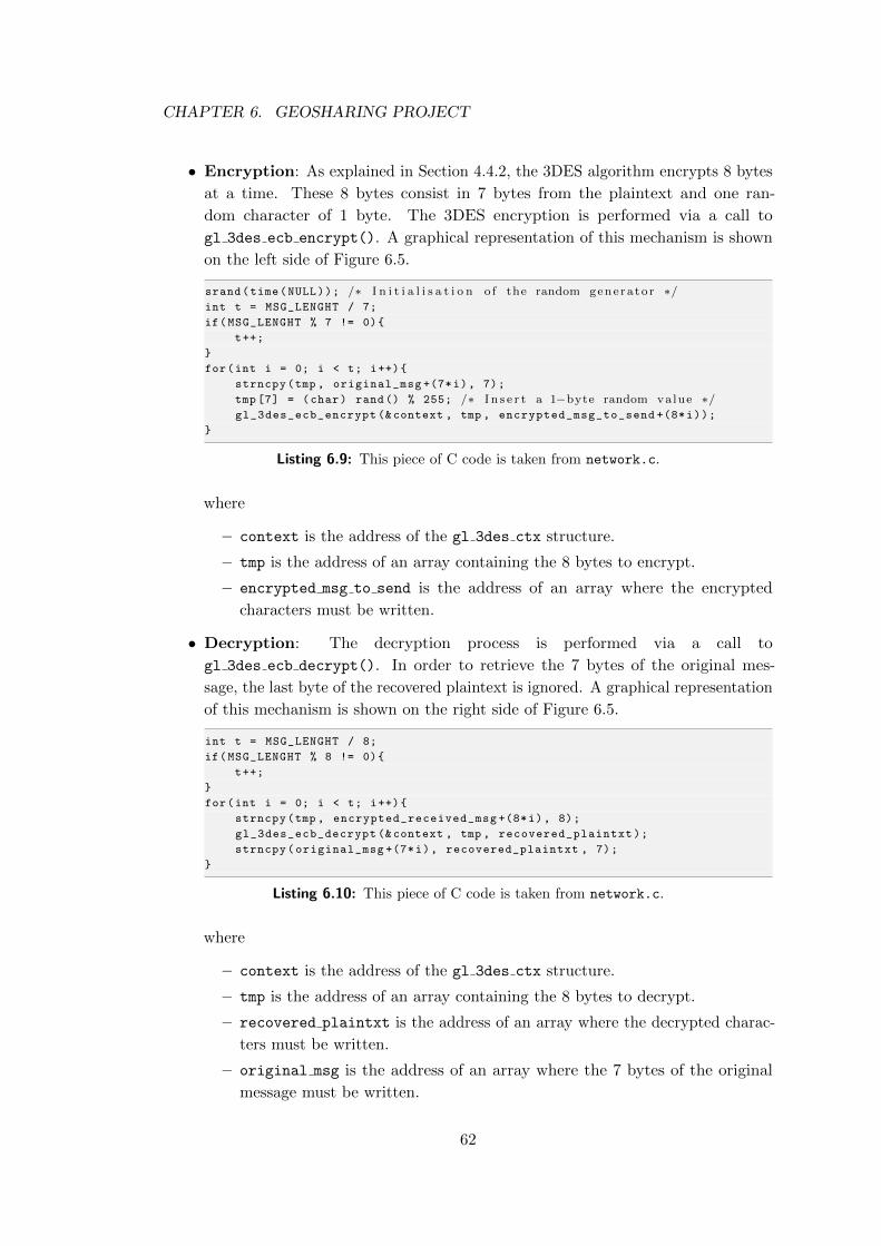
CHAPTER 6. GEOSHARING PROJECT
• Encryption: As explained in Section 4.4.2, the 3DES algorithm encrypts 8 bytes
at a time. These 8 bytes consist in 7 bytes from the plaintext and one ran-
dom character of 1 byte. The 3DES encryption is performed via a call to
gl 3des ecb encrypt(). A graphical representation of this mechanism is shown
on the left side of Figure 6.5.
srand(time(NULL)); /∗ I n i t i a l i s a t i o n o f the random genera to r ∗/int t = MSG_LENGHT / 7;
if(MSG_LENGHT % 7 != 0){
t++;
}
for(int i = 0; i < t; i++){
strncpy(tmp , original_msg +(7*i), 7);
tmp [7] = (char) rand() % 255; /∗ I n s e r t a 1−byte random value ∗/gl_3des_ecb_encrypt (&context , tmp , encrypted_msg_to_send +(8*i));
}
Listing 6.9: This piece of C code is taken from network.c.
where
– context is the address of the gl 3des ctx structure.
– tmp is the address of an array containing the 8 bytes to encrypt.
– encrypted msg to send is the address of an array where the encrypted
characters must be written.
• Decryption: The decryption process is performed via a call to
gl 3des ecb decrypt(). In order to retrieve the 7 bytes of the original mes-
sage, the last byte of the recovered plaintext is ignored. A graphical representation
of this mechanism is shown on the right side of Figure 6.5.
int t = MSG_LENGHT / 8;
if(MSG_LENGHT % 8 != 0){
t++;
}
for(int i = 0; i < t; i++){
strncpy(tmp , encrypted_received_msg +(8*i), 8);
gl_3des_ecb_decrypt (&context , tmp , recovered_plaintxt);
strncpy(original_msg +(7*i), recovered_plaintxt , 7);
}
Listing 6.10: This piece of C code is taken from network.c.
where
– context is the address of the gl 3des ctx structure.
– tmp is the address of an array containing the 8 bytes to decrypt.
– recovered plaintxt is the address of an array where the decrypted charac-
ters must be written.
– original msg is the address of an array where the 7 bytes of the original
message must be written.
62
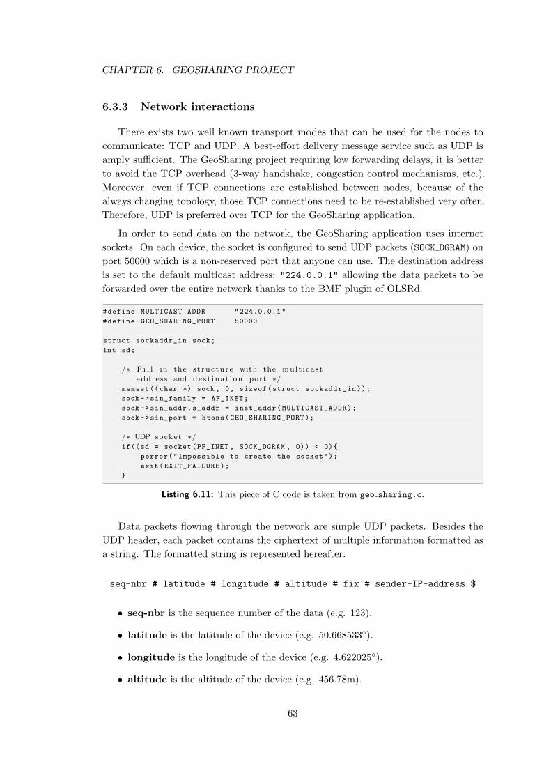
CHAPTER 6. GEOSHARING PROJECT
6.3.3 Network interactions
There exists two well known transport modes that can be used for the nodes to
communicate: TCP and UDP. A best-effort delivery message service such as UDP is
amply sufficient. The GeoSharing project requiring low forwarding delays, it is better
to avoid the TCP overhead (3-way handshake, congestion control mechanisms, etc.).
Moreover, even if TCP connections are established between nodes, because of the
always changing topology, those TCP connections need to be re-established very often.
Therefore, UDP is preferred over TCP for the GeoSharing application.
In order to send data on the network, the GeoSharing application uses internet
sockets. On each device, the socket is configured to send UDP packets (SOCK DGRAM) on
port 50000 which is a non-reserved port that anyone can use. The destination address
is set to the default multicast address: "224.0.0.1" allowing the data packets to be
forwarded over the entire network thanks to the BMF plugin of OLSRd.
#define MULTICAST_ADDR "224.0.0.1"
#define GEO_SHARING_PORT 50000
struct sockaddr_in sock;
int sd;
/∗ F i l l in the s t r u c tu r e with the mu l t i c a s t
address and de s t i n a t i on port ∗/memset ((char *) sock , 0, sizeof(struct sockaddr_in));
sock ->sin_family = AF_INET;
sock ->sin_addr.s_addr = inet_addr(MULTICAST_ADDR);
sock ->sin_port = htons(GEO_SHARING_PORT);
/∗ UDP socket ∗/if((sd = socket(PF_INET , SOCK_DGRAM , 0)) < 0){
perror("Impossible to create the socket");
exit(EXIT_FAILURE);
}
Listing 6.11: This piece of C code is taken from geo sharing.c.
Data packets flowing through the network are simple UDP packets. Besides the
UDP header, each packet contains the ciphertext of multiple information formatted as
a string. The formatted string is represented hereafter.
seq-nbr # latitude # longitude # altitude # fix # sender-IP-address $
• seq-nbr is the sequence number of the data (e.g. 123).
• latitude is the latitude of the device (e.g. 50.668533◦).
• longitude is the longitude of the device (e.g. 4.622025◦).
• altitude is the altitude of the device (e.g. 456.78m).
63
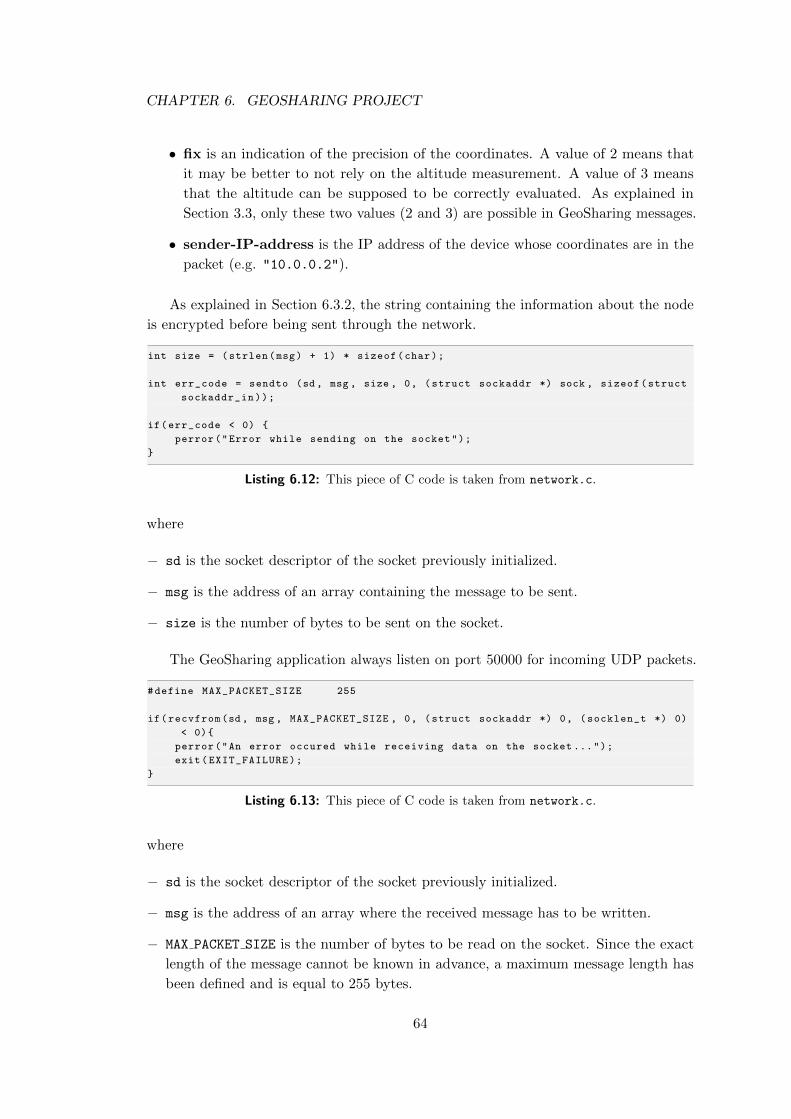
CHAPTER 6. GEOSHARING PROJECT
• fix is an indication of the precision of the coordinates. A value of 2 means that
it may be better to not rely on the altitude measurement. A value of 3 means
that the altitude can be supposed to be correctly evaluated. As explained in
Section 3.3, only these two values (2 and 3) are possible in GeoSharing messages.
• sender-IP-address is the IP address of the device whose coordinates are in the
packet (e.g. "10.0.0.2").
As explained in Section 6.3.2, the string containing the information about the node
is encrypted before being sent through the network.
int size = (strlen(msg) + 1) * sizeof(char);
int err_code = sendto (sd, msg , size , 0, (struct sockaddr *) sock , sizeof(struct
sockaddr_in));
if(err_code < 0) {
perror("Error while sending on the socket");
}
Listing 6.12: This piece of C code is taken from network.c.
where
− sd is the socket descriptor of the socket previously initialized.
− msg is the address of an array containing the message to be sent.
− size is the number of bytes to be sent on the socket.
The GeoSharing application always listen on port 50000 for incoming UDP packets.
#define MAX_PACKET_SIZE 255
if(recvfrom(sd, msg , MAX_PACKET_SIZE , 0, (struct sockaddr *) 0, (socklen_t *) 0)
< 0){
perror("An error occured while receiving data on the socket ...");
exit(EXIT_FAILURE);
}
Listing 6.13: This piece of C code is taken from network.c.
where
− sd is the socket descriptor of the socket previously initialized.
− msg is the address of an array where the received message has to be written.
− MAX PACKET SIZE is the number of bytes to be read on the socket. Since the exact
length of the message cannot be known in advance, a maximum message length has
been defined and is equal to 255 bytes.
64
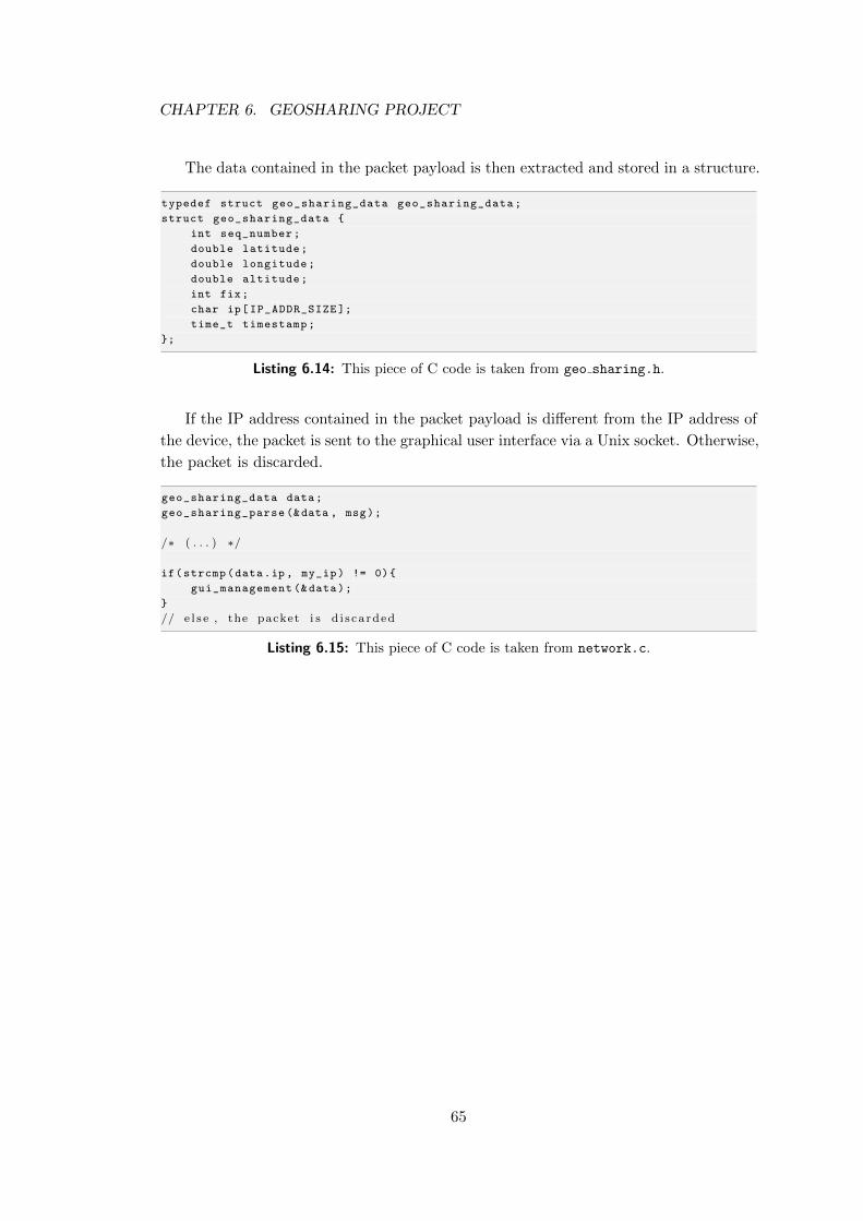
CHAPTER 6. GEOSHARING PROJECT
The data contained in the packet payload is then extracted and stored in a structure.
typedef struct geo_sharing_data geo_sharing_data;
struct geo_sharing_data {
int seq_number;
double latitude;
double longitude;
double altitude;
int fix;
char ip[IP_ADDR_SIZE ];
time_t timestamp;
};
Listing 6.14: This piece of C code is taken from geo sharing.h.
If the IP address contained in the packet payload is different from the IP address of
the device, the packet is sent to the graphical user interface via a Unix socket. Otherwise,
the packet is discarded.
geo_sharing_data data;
geo_sharing_parse (&data , msg);
/∗ ( . . . ) ∗/
if(strcmp(data.ip, my_ip) != 0){
gui_management (&data);
}
// e l s e , the packet i s d i s ca rded
Listing 6.15: This piece of C code is taken from network.c.
65
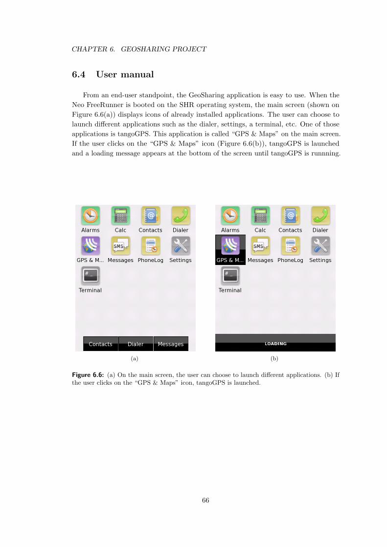
CHAPTER 6. GEOSHARING PROJECT
6.4 User manual
From an end-user standpoint, the GeoSharing application is easy to use. When the
Neo FreeRunner is booted on the SHR operating system, the main screen (shown on
Figure 6.6(a)) displays icons of already installed applications. The user can choose to
launch different applications such as the dialer, settings, a terminal, etc. One of those
applications is tangoGPS. This application is called “GPS & Maps” on the main screen.
If the user clicks on the “GPS & Maps” icon (Figure 6.6(b)), tangoGPS is launched
and a loading message appears at the bottom of the screen until tangoGPS is runnning.
(a) (b)
Figure 6.6: (a) On the main screen, the user can choose to launch different applications. (b) Ifthe user clicks on the “GPS & Maps” icon, tangoGPS is launched.
66
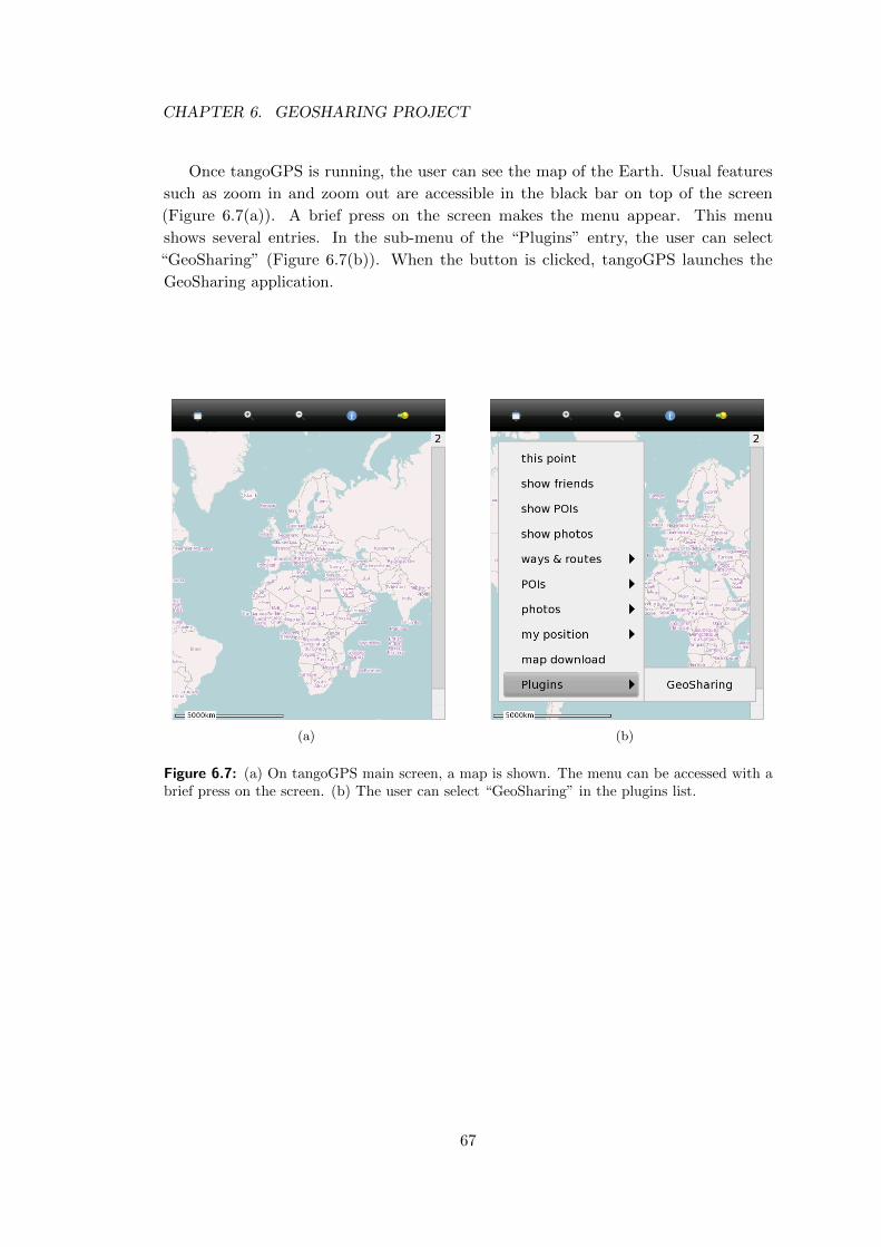
CHAPTER 6. GEOSHARING PROJECT
Once tangoGPS is running, the user can see the map of the Earth. Usual features
such as zoom in and zoom out are accessible in the black bar on top of the screen
(Figure 6.7(a)). A brief press on the screen makes the menu appear. This menu
shows several entries. In the sub-menu of the “Plugins” entry, the user can select
“GeoSharing” (Figure 6.7(b)). When the button is clicked, tangoGPS launches the
GeoSharing application.
(a) (b)
Figure 6.7: (a) On tangoGPS main screen, a map is shown. The menu can be accessed with abrief press on the screen. (b) The user can select “GeoSharing” in the plugins list.
67
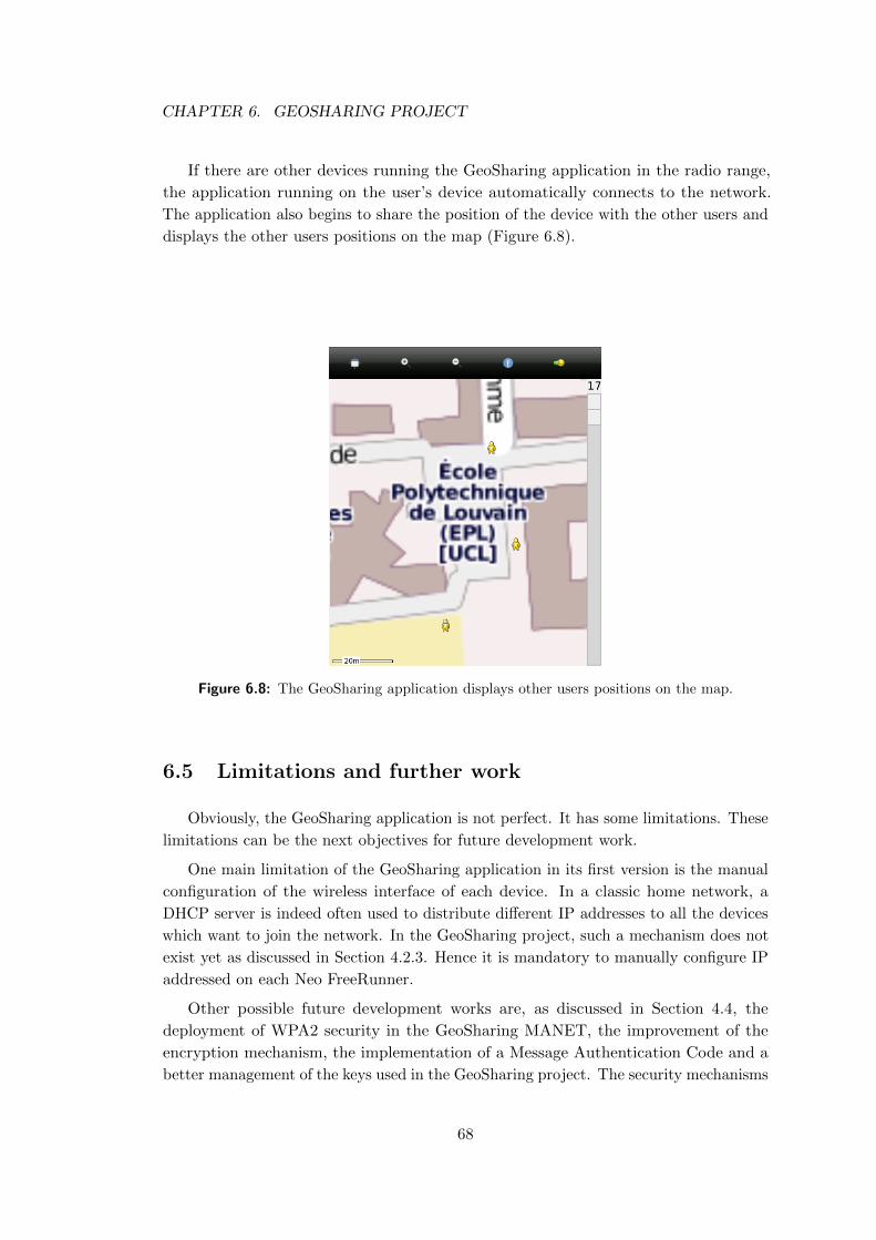
CHAPTER 6. GEOSHARING PROJECT
If there are other devices running the GeoSharing application in the radio range,
the application running on the user’s device automatically connects to the network.
The application also begins to share the position of the device with the other users and
displays the other users positions on the map (Figure 6.8).
Figure 6.8: The GeoSharing application displays other users positions on the map.
6.5 Limitations and further work
Obviously, the GeoSharing application is not perfect. It has some limitations. These
limitations can be the next objectives for future development work.
One main limitation of the GeoSharing application in its first version is the manual
configuration of the wireless interface of each device. In a classic home network, a
DHCP server is indeed often used to distribute different IP addresses to all the devices
which want to join the network. In the GeoSharing project, such a mechanism does not
exist yet as discussed in Section 4.2.3. Hence it is mandatory to manually configure IP
addressed on each Neo FreeRunner.
Other possible future development works are, as discussed in Section 4.4, the
deployment of WPA2 security in the GeoSharing MANET, the improvement of the
encryption mechanism, the implementation of a Message Authentication Code and a
better management of the keys used in the GeoSharing project. The security mechanisms
68
CHAPTER 6. GEOSHARING PROJECT
involved in the first version of the GeoSharing project consist in a combination of a
WEP-secured wireless network and a 3DES encryption scheme of the sensitive data.
• Since a WEP key can nowadays easily be found by an attacker, the WEP security
is more a mechanism to force attackers to do something illegal if they want to
eavesdrop on the network. The WEP should be replaced by a stronger security
scheme such as WPA2 which is a standard believed to be stronger than WEP.
The deployment of WPA2 could be an added value for the GeoSharing project.
• In the current version of the GeoSharing project, 3DES in ECB mode is used
to encrypt and decrypt sensitive data. Since this mode does not provide a total
privacy in certain conditions (described in Section 4.4.2), the analysis of other
modes of 3DES or other encryption algorithms could be the focus of further work
in order to find a better solution.
• A Message Authentication Code mechanism could be added to the GeoSharing
application in order to provide an integrity check for each packet coming from
another node of the network. An analysis of the different keyed hash function
that can be used in MAC schemes has to be performed. The implementation of
such a mechanism could be, as well as the WPA2 deployment, an added value for
the GeoSharing project.
• In the current version of the GeoSharing project, four different keys have to be
used. The WEP-key is stored in the clear in the /etc/network/interfaces
configuration file. The three keys used for the 3DES algorithm are hard-coded
in the network.c source file of the GeoSharing application. An analysis of more
secured places to store those credentials have to be performed to prevent attackers
to have a direct access the the keys if a device is compromised. This more secured
place should be easily accessible by the GeoSharing application while providing a
high level of security.
A last possible improvement is the development of a stand-alone graphical user
interface as discussed in Section 5.3. The solution currently proposed with the GeoShar-
ing application is reliable but not optimized for CPU and memory utilization. The
installation of tangoGPS is indeed required and lots of tangoGPS functionalities are
useless for the GeoSharing project.
69
Conclusion
Nowadays, the demand for geo-positioning systems is growing because of the large
number of possible application domains such as companies which want to track their
goods in their warehouse, companies which want to track their vehicles, military head-
quarters which want to track their soldiers, etc. There also exists applications developed
in the scope of social networks where users like sharing their current geographical posi-
tion with their friends (e.g. Facebook Places, Foursquare, Mobbyway). Most of those
applications need a connection to the internet. The GeoSharing project differs from all
those examples by the way it uses to share geographical positions. With GeoSharing,
the geographical positions are indeed directly shared over a network of connected devices
without the need of an internet connection or any additional infrastructure.
The military sector is a precursor in this domain mainly because this sector needs
systems that can be used in many different places and in many environments where a
connection to the internet is not always straightforward. For example, an American
company (called Mesh Dynamics) has developed a product dedicated to Military, Defence
and Public Safety. The name of this project is P3M for Persistent Third-Generation
Mesh [Mob11]. The main difference between the P3M project and the GeoSharing
project is that P3M is more focused on communication data (voice over IP, video, etc.)
while GeoSharing is more specific for real-time location.
Wireless ad hoc networks are also widespread in sensor networks. Military sensor
networks can be used to collect information about enemy movements or to track enemy
vehicles moving around the network nodes.
Another project whose aim is to allow each node belonging to a mesh network to
get an internet access has been implemented an is called MokoMesh. The main idea
is to use a single GPRS connection on one phone and share this internet connectivity
with all nodes over the network.
The GeoSharing project proposes geoposition sharing system based on Openmoko.
Openmoko Neo FreeRunner devices running SHR, a Linux-based operating system, are
used. This operating system choice is compliant with the prerequisites of such a project
that are stability, maintenance, widespread usage and low energy consumption. The
underlying network established for position sharing is build and maintained thanks to a
Linux dæmon implementing the Optimized Link State Routing protocol (OLSR). This
70
CHAPTER 6. GEOSHARING PROJECT
dæmon fits very well the needs of the GeoSharing application since it guarantees an
efficient topology and routing tables management at a very low cost in term of CPU
and memory usage. It is therefore well adapted for low power mobile devices such as the
Openmoko Neo FreeRunner. The entire GeoSharing application is interfaced with an
already existing open source navigation application called tangoGPS. It is integrated as
a lightweight plugin displaying the position of every node belonging to the application
network. This solution provides an additional feature to tangoGPS and can be executed
in parallel to other functionalities such as point of interests display, etc. Furthermore,
the main features of tangoGPS can be exploited allowing the user to zoom and slide
the map. The major drawback of the solution as it is proposed is that the tangoGPS
application and the GeoSharing plugin for tangoGPS must be installed. It is indeed an
important investment even if tangoGPS has been developed for mobile devices. The
GeoSharing project is integrated in geo-positioning applications by bringing a new way
to share geographical position through a network.
Since this project can be reused by other people or by studies, GeoSharing is available
as an open-source application. The GeoSharing project is still alive. Thanks to the
website and the wiki, interactions with people who want to do something with this work
are facilitated.
• The website: http://www.geosharing-project.org
• The wiki: http://wiki.geosharing-project.org
• The sources: http://sources.geosharing-project.org
71
Appendix A
Installation guide
This appendix is divided into two parts. The first part presents preliminary con-
figurations that must be done before starting any development on the Opemoko Neo
FreeRunner (GTA02). The second part describes the technical steps to follow in order
to install the GeoSharing project on the Neo FreeRunner.
All those steps have been tested on a Neo FreeRunner and on a laptop running
Ubuntu 10.10 with access to root privileges.
A.1 Preliminary configurations
This section consists in three parts. The first thing to do is to configure a connection
between the Neo FreeRunner and a computer via a USB cable. Most of the operations
that must be executed on the Neo FreeRunner are easily performed on a computer
disposing of a keyboard and a larger screen than the GTA02. A SSH connection should
thus be established from the computer to the Neo FreeRunner in order to have access
to it.
The second part details the installation steps of an operating system (OS) on the
Neo FreeRunner. This operation is made possible thanks to the communication channel
created before via the USB cable. The operating system called SHR was chosen to be
used in the scope of the GeoSharing project.
The third part shows how it is possible to share the internet connection of a computer
with the Neo FreeRunner via the USB cable.
A.1.1 USB interface configuration
An important thing to notice is that the USB connectivity is considered as an
ethernet connection by both the Neo FreeRunner and the computer. This implies
the use of IP addresses to identify both ends of the connection. By default, the Neo
72
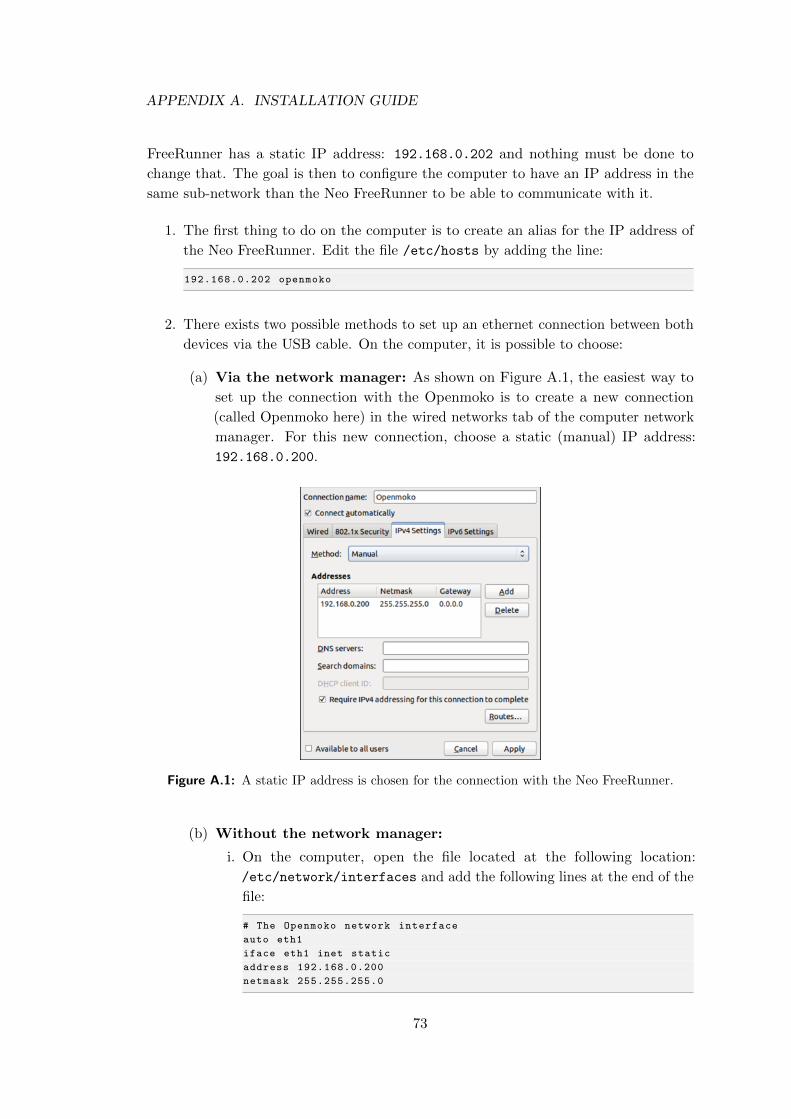
APPENDIX A. INSTALLATION GUIDE
FreeRunner has a static IP address: 192.168.0.202 and nothing must be done to
change that. The goal is then to configure the computer to have an IP address in the
same sub-network than the Neo FreeRunner to be able to communicate with it.
1. The first thing to do on the computer is to create an alias for the IP address of
the Neo FreeRunner. Edit the file /etc/hosts by adding the line:
192.168.0.202 openmoko
2. There exists two possible methods to set up an ethernet connection between both
devices via the USB cable. On the computer, it is possible to choose:
(a) Via the network manager: As shown on Figure A.1, the easiest way to
set up the connection with the Openmoko is to create a new connection
(called Openmoko here) in the wired networks tab of the computer network
manager. For this new connection, choose a static (manual) IP address:
192.168.0.200.
Figure A.1: A static IP address is chosen for the connection with the Neo FreeRunner.
(b) Without the network manager:
i. On the computer, open the file located at the following location:
/etc/network/interfaces and add the following lines at the end of the
file:
# The Openmoko network interface
auto eth1
iface eth1 inet static
address 192.168.0.200
netmask 255.255.255.0
73
APPENDIX A. INSTALLATION GUIDE
ii. On the computer, restart the network service by running the following
command as root:
# /etc/init.d/networking restart
3. If an operational OS is running a SSH dæmon on the Neo FreeRunner, it is possible
to establish an SSH connection from the computer to the root session of the Neo
FreeRunner.
$ ssh root@openmoko
root@om -gta02 ~ #
If it is not the case (i.e. there is no SSH dæmon or no operating system at all),
the Neo FreeRunner can be flashed with, for example, the operating system used
in the scope of the GeoSharing project: SHR.
A.1.2 Flashing the SHR operating system on the Neo FreeRunner
The easiest way to flash the Neo FreeRunner is to use neoTool on the computer. It
is mandatory to install dfu-utils via the Synaptic Package Manager of the computer
before running neoTool. The version of neoTool that have been used to realise this
manual is the version 1.3.
Before going any further, the Neo FreeRunner must be connected to the computer
with the USB cable, the IP address of each device must have been previously configured
(See Appendix A.1.1) and the Neo FreeRunner must be booted on the NOR memory as
explained in Section 1.3.3 of this document (POWER + AUX buttons).
1. The first step is to copy the bash script that can be found at
http://users.on.net/∼antisol/neotool into an empty file on the computer. Rename
this file neoTool and give it the execution rights.
$ chmod u+x neoTool
2. The second step is to run neoTool on the computer with root privileges.
$ sudo ./ neoTool
74
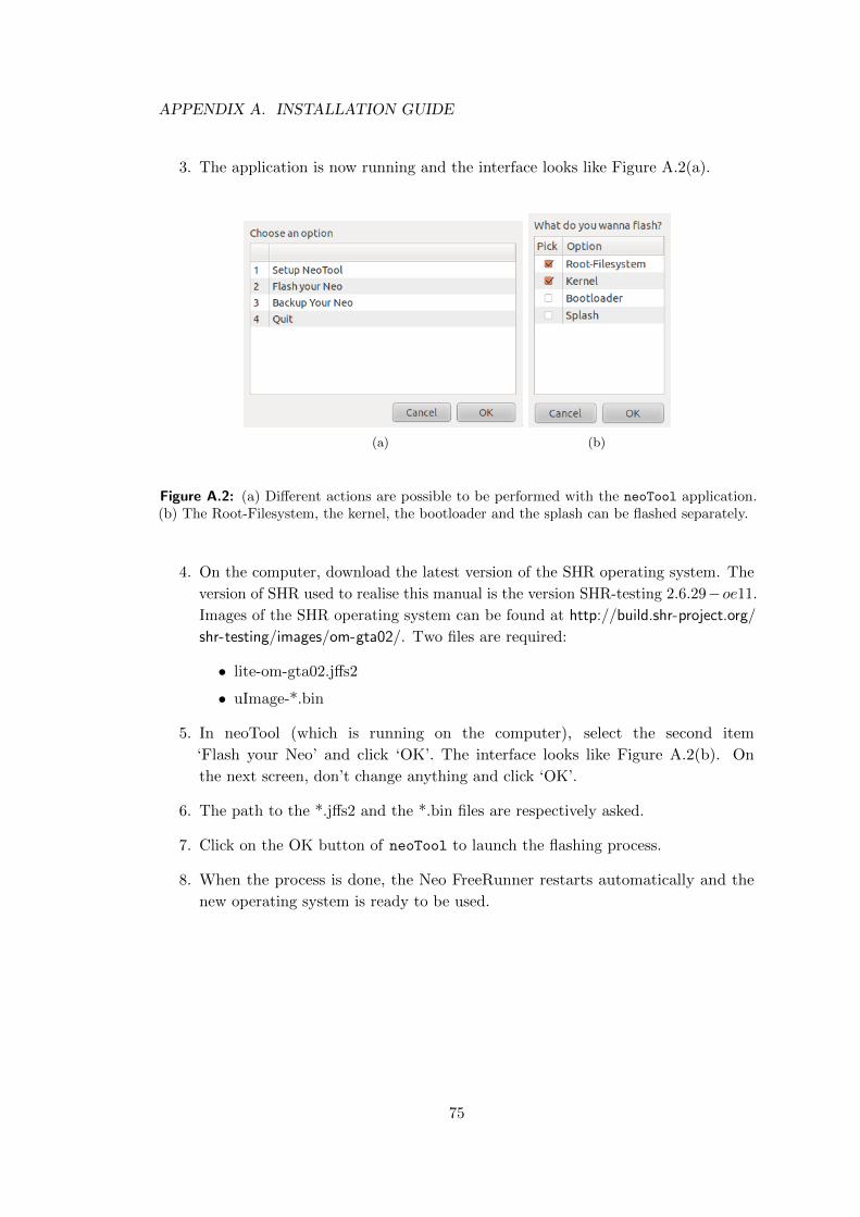
APPENDIX A. INSTALLATION GUIDE
3. The application is now running and the interface looks like Figure A.2(a).
(a) (b)
Figure A.2: (a) Different actions are possible to be performed with the neoTool application.(b) The Root-Filesystem, the kernel, the bootloader and the splash can be flashed separately.
4. On the computer, download the latest version of the SHR operating system. The
version of SHR used to realise this manual is the version SHR-testing 2.6.29−oe11.
Images of the SHR operating system can be found at http://build.shr-project.org/
shr-testing/images/om-gta02/. Two files are required:
• lite-om-gta02.jffs2
• uImage-*.bin
5. In neoTool (which is running on the computer), select the second item
‘Flash your Neo’ and click ‘OK’. The interface looks like Figure A.2(b). On
the next screen, don’t change anything and click ‘OK’.
6. The path to the *.jffs2 and the *.bin files are respectively asked.
7. Click on the OK button of neoTool to launch the flashing process.
8. When the process is done, the Neo FreeRunner restarts automatically and the
new operating system is ready to be used.
75
APPENDIX A. INSTALLATION GUIDE
A.1.3 Internet connectivity
When the operating system is installed and running, the configuration steps required
in order to share the internet connectivity of the computer with the Neo FreeRunner via
the USB cable are the followings. These steps must be done on the computer connected
to the Neo FreeRunner.
1. On the computer, edit the file /etc/sysctl.conf
$ gedit /etc/sysctl.conf
2. Look for the following line in this file:
#net.ipv4.conf.default.forwarding =1
and uncomment it (remove the # character if not already done).
3. The iptables of the computer must be configured such that the computer behaves
as a simple router for the Openmoko. The computer must forward packets coming
from the Neo FreeRunner to the internet and the other way around. Edit the file
/etc/rc.local:
$ gedit /etc/rc.local
and add these lines at the end of the file:
/sbin/iptables -P FORWARD ACCEPT
/sbin/iptables --table nat -A POSTROUTING -s 192.168.0.202/32 -o iface -j
MASQUERADE
where iface corresponds to the interface of the computer connected to the internet
(wlan0, eth0, eth1, ...).
4. The computer have now to be rebooted.
The internet connection of the computer is now shared with the Neo FreeRunner. In
order to check if the sharing of the internet connection is well configured, from the Neo
FreeRunner, perform a ping to www.google.com and the results should look like this:
root@om -gta02 ~ # ping www.google.com
PING www.google.com (66.102.13.103): 56 data bytes
64 bytes from 66.102.13.103: seq=0 ttl=55 time =19.548 ms
64 bytes from 66.102.13.103: seq=1 ttl=55 time =35.519 ms
(...)
76
APPENDIX A. INSTALLATION GUIDE
A.2 GeoSharing project installation
Since the GeoSharing project is based on the OLSRd Linux dæmon and on tangoGPS,
it is mandatory to compile and install those two applications as well as the GeoSharing
application.
Before going any further, extra packages such as a C compiler (gcc) and libraries
(libglib, libconfig, libgps, etc.) need to be installed on the Neo FreeRunner. In
order to install these packages, an internet connection is required. The following
commands must then be executed on the Neo FreeRunner.
root@om -gta02 ~ # opkg update
root@om -gta02 ~ # opkg upgrade
root@om -gta02 ~ # opkg install make gcc gcc -symlinks libc6 libc6 -dev binutils
binutils -symlinks coreutils kernel -module -tun kernel -module -tunnel4 mdbus
libglib -2.0-dev libdbus -glib -1-dev gconf orbit2 libidl -2-0 policykit eggdbus
libexif12 libgps gpsd -dev gtk+ gconf libxml2 -dev libsoup -2.4-dev bluez4 -dev
curl curl -dev libexif -dev libconfig -dev
Listing A.1: Packages to install on the Neo FreeRunner.
Now that the needed packages are installed, OLSRd, tangoGPS and the GeoSharing
application can be compiled and installed on the Neo FreeRunner.
A.2.1 OLSRd Linux dæmon
As stated in Section 6.1, the compilation process of OLSRd requires bison and flex
packages to compile the syntactical analyser used inside OLSRd. Since the version of
SHR proposed in this manual does not provide those packages (bison and flex) in
the package repository, the compilation of the syntactical analyser have to be done on
another version of the OS.
The entire compilation and installation process of OLSRd on the Neo FreeRunner is
detailed in the following steps. Some steps are performed on a Neo FreeRunner running
the SHR-unstable version of the operating system while some other steps are performed
on the SHR-testing version. The SHR-unstable version provides much more packages in
the package repository. Bison and flex are fortunately part of the list. On the Neo
FreeRunner running the SHR-unstable version, all the packages listed in Listing A.1
have been installed. In addition to them, bison and flex have been installed as well.
A computer is used to easily manage file transfers between the Neo FreeRunner
devices.
77
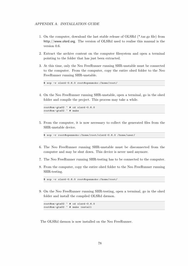
APPENDIX A. INSTALLATION GUIDE
1. On the computer, download the last stable release of OLSRd (*.tar.gz file) from
http://www.olsrd.org. The version of OLSRd used to realise this manual is the
version 0.6.
2. Extract the archive content on the computer filesystem and open a terminal
pointing to the folder that has just been extracted.
3. At this time, only the Neo FreeRunner running SHR-unstable must be connected
to the computer. From the computer, copy the entire olsrd folder to the Neo
FreeRunner running SHR-unstable.
$ scp -r olsrd -0.6.0 root@openmoko :/home/root/
4. On the Neo FreeRunner running SHR-unstable, open a terminal, go in the olsrd
folder and compile the project. This process may take a while.
root@om -gta02 ~ # cd olsrd -0.6.0
root@om -gta02 ~ # make
5. From the computer, it is now necessary to collect the generated files from the
SHR-unstable device.
$ scp -r root@openmoko :/home/root/olsrd -0.6.0 /home/user/
6. The Neo FreeRunner running SHR-unstable must be disconnected from the
computer and may be shut down. This device is never used anymore.
7. The Neo FreeRunner running SHR-testing has to be connected to the computer.
8. From the computer, copy the entire olsrd folder to the Neo FreeRunner running
SHR-testing.
$ scp -r olsrd -0.6.0 root@openmoko :/home/root/
9. On the Neo FreeRunner running SHR-testing, open a terminal, go in the olsrd
folder and install the compiled OLSRd dæmon.
root@om -gta02 ~ # cd olsrd -0.6.0
root@om -gta02 ~ # make install
The OLSRd dæmon is now installed on the Neo FreeRunner.
78
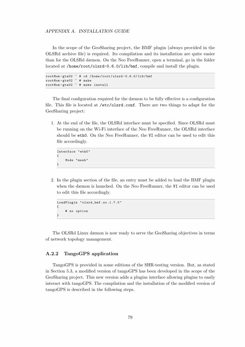
APPENDIX A. INSTALLATION GUIDE
In the scope of the GeoSharing project, the BMF plugin (always provided in the
OLSRd archive file) is required. Its compilation and its installation are quite easier
than for the OLSRd dæmon. On the Neo FreeRunner, open a terminal, go in the folder
located at /home/root/olsrd-0.6.0/lib/bmf, compile and install the plugin.
root@om -gta02 ~ # cd /home/root/olsrd -0.6.0/ lib/bmf
root@om -gta02 ~ # make
root@om -gta02 ~ # make install
The final configuration required for the dæmon to be fully effective is a configuration
file. This file is located at /etc/olsrd.conf. There are two things to adapt for the
GeoSharing project:
1. At the end of the file, the OLSRd interface must be specified. Since OLSRd must
be running on the Wi-Fi interface of the Neo FreeRunner, the OLSRd interface
should be eth0. On the Neo FreeRunner, the VI editor can be used to edit this
file accordingly.
Interface "eth0"
{
Mode "mesh"
}
2. In the plugin section of the file, an entry must be added to load the BMF plugin
when the dæmon is launched. On the Neo FreeRunner, the VI editor can be used
to edit this file accordingly.
LoadPlugin "olsrd_bmf.so .1.7.0"
{
# no option
}
The OLSRd Linux dæmon is now ready to serve the GeoSharing objectives in terms
of network topology management.
A.2.2 TangoGPS application
TangoGPS is provided in some editions of the SHR-testing version. But, as stated
in Section 5.3, a modified version of tangoGPS has been developed in the scope of the
GeoSharing project. This new version adds a plugins interface allowing plugins to easily
interact with tangoGPS. The compilation and the installation of the modified version of
tangoGPS is described in the following steps.
79
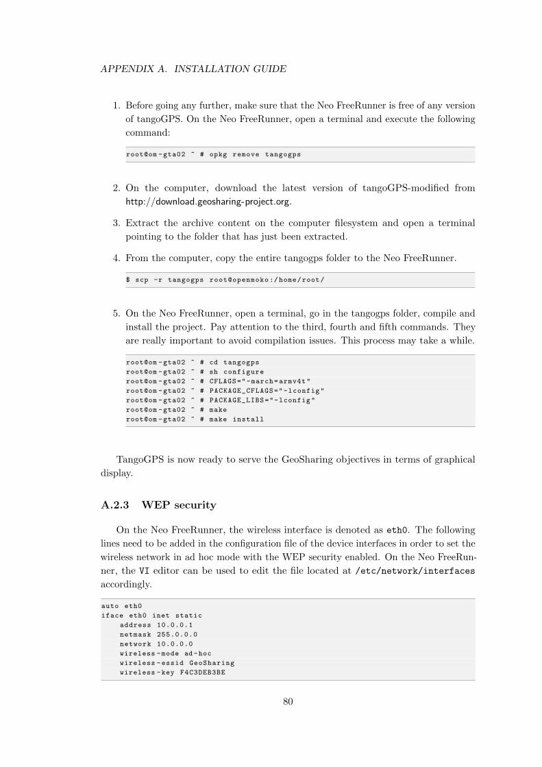
APPENDIX A. INSTALLATION GUIDE
1. Before going any further, make sure that the Neo FreeRunner is free of any version
of tangoGPS. On the Neo FreeRunner, open a terminal and execute the following
command:
root@om -gta02 ~ # opkg remove tangogps
2. On the computer, download the latest version of tangoGPS-modified from
http://download.geosharing-project.org.
3. Extract the archive content on the computer filesystem and open a terminal
pointing to the folder that has just been extracted.
4. From the computer, copy the entire tangogps folder to the Neo FreeRunner.
$ scp -r tangogps root@openmoko :/home/root/
5. On the Neo FreeRunner, open a terminal, go in the tangogps folder, compile and
install the project. Pay attention to the third, fourth and fifth commands. They
are really important to avoid compilation issues. This process may take a while.
root@om -gta02 ~ # cd tangogps
root@om -gta02 ~ # sh configure
root@om -gta02 ~ # CFLAGS="-march=armv4t"
root@om -gta02 ~ # PACKAGE_CFLAGS="-lconfig"
root@om -gta02 ~ # PACKAGE_LIBS="-lconfig"
root@om -gta02 ~ # make
root@om -gta02 ~ # make install
TangoGPS is now ready to serve the GeoSharing objectives in terms of graphical
display.
A.2.3 WEP security
On the Neo FreeRunner, the wireless interface is denoted as eth0. The following
lines need to be added in the configuration file of the device interfaces in order to set the
wireless network in ad hoc mode with the WEP security enabled. On the Neo FreeRun-
ner, the VI editor can be used to edit the file located at /etc/network/interfaces
accordingly.
auto eth0
iface eth0 inet static
address 10.0.0.1
netmask 255.0.0.0
network 10.0.0.0
wireless -mode ad -hoc
wireless -essid GeoSharing
wireless -key F4C3DEB3BE
80
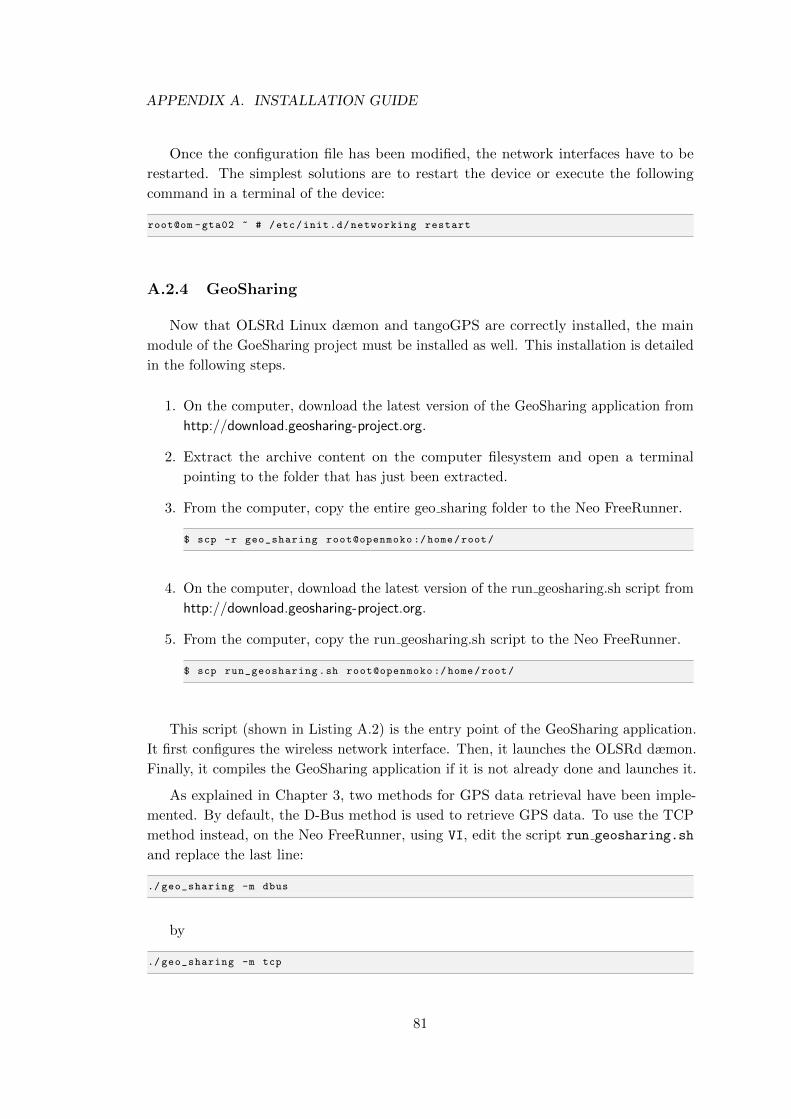
APPENDIX A. INSTALLATION GUIDE
Once the configuration file has been modified, the network interfaces have to be
restarted. The simplest solutions are to restart the device or execute the following
command in a terminal of the device:
root@om -gta02 ~ # /etc/init.d/networking restart
A.2.4 GeoSharing
Now that OLSRd Linux dæmon and tangoGPS are correctly installed, the main
module of the GoeSharing project must be installed as well. This installation is detailed
in the following steps.
1. On the computer, download the latest version of the GeoSharing application from
http://download.geosharing-project.org.
2. Extract the archive content on the computer filesystem and open a terminal
pointing to the folder that has just been extracted.
3. From the computer, copy the entire geo sharing folder to the Neo FreeRunner.
$ scp -r geo_sharing root@openmoko :/home/root/
4. On the computer, download the latest version of the run geosharing.sh script from
http://download.geosharing-project.org.
5. From the computer, copy the run geosharing.sh script to the Neo FreeRunner.
$ scp run_geosharing.sh root@openmoko :/home/root/
This script (shown in Listing A.2) is the entry point of the GeoSharing application.
It first configures the wireless network interface. Then, it launches the OLSRd dæmon.
Finally, it compiles the GeoSharing application if it is not already done and launches it.
As explained in Chapter 3, two methods for GPS data retrieval have been imple-
mented. By default, the D-Bus method is used to retrieve GPS data. To use the TCP
method instead, on the Neo FreeRunner, using VI, edit the script run geosharing.sh
and replace the last line:
./ geo_sharing -m dbus
by
./ geo_sharing -m tcp
81
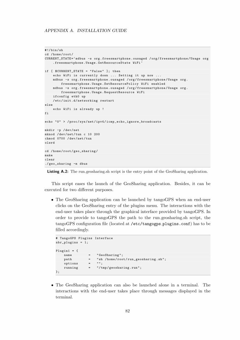
APPENDIX A. INSTALLATION GUIDE
#!/bin/sh
cd /home/root/
CURRENT_STATE=‘mdbus -s org.freesmartphone.ousaged /org/freesmartphone/Usage org
.freesmartphone.Usage.GetResourceState WiFi ‘
if [ $CURRENT_STATE = "False" ]; then
echo WiFi is currently down ... Setting it up now ...
mdbus -s org.freesmartphone.ousaged /org/freesmartphone/Usage org.
freesmartphone.Usage.SetResourcePolicy WiFi enabled
mdbus -s org.freesmartphone.ousaged /org/freesmartphone/Usage org.
freesmartphone.Usage.RequestResource WiFi
ifconfig eth0 up
/etc/init.d/networking restart
else
echo WiFi is already up !
fi
echo "0" > /proc/sys/net/ipv4/icmp_echo_ignore_broadcasts
mkdir -p /dev/net
mknod /dev/net/tun c 10 200
chmod 0700 /dev/net/tun
olsrd
cd /home/root/geo_sharing/
make
clear
./ geo_sharing -m dbus
Listing A.2: The run geosharing.sh script is the entry point of the GeoSharing application.
This script eases the launch of the GeoSharing application. Besides, it can be
executed for two different purposes.
• The GeoSharing application can be launched by tangoGPS when an end-user
clicks on the GeoSharing entry of the plugins menu. The interactions with the
end-user takes place through the graphical interface provided by tangoGPS. In
order to provide to tangoGPS the path to the run geosharing.sh script, the
tangoGPS configuration file (located at /etc/tangogps plugins.conf) has to be
filled accordingly.
# TangoGPS Plugins Interface
nbr_plugins = 1;
Plugin1 = {
name = "GeoSharing";
path = "sh /home/root/run_geosharing.sh";
options = "";
running = "/tmp/geosharing.run";
};
• The GeoSharing application can also be launched alone in a terminal. The
interactions with the end-user takes place through messages displayed in the
terminal.
82

Appendix B
Licence
GeoSharing is distributed under the “Creative Commons BY SA”1.
• You are free:
– to Share — to copy, distribute and transmit the work
– to Remix — to adapt the work
• Under the following conditions:
– Attribution — You must attribute the work in the manner specified by the
author or licensor (but not in any way that suggests that they endorse you
or your use of the work).
– Share Alike — If you alter, transform, or build upon this work, you may
distribute the resulting work only under the same or similar license to this
one.
1 http://creativecommons.org/licenses/by-sa/3.0/legalcode
83
Bibliography
[ABF05] N. Mitton A. Busson and E. Fleury. An analysis of the Multi-Point Relays
selection in OLSR. http://www.lri.fr/∼fragile/IMG/pdf/RR-5468 analyseMPR.
pdf, 2005.
[Ant] Antaris4, Single-chip GPS Receiver SuperSense ATR063. http://www.atmel.
com/dyn/resources/prod documents/doc4928.pdf.
[Avo11] Prof. Gildas Avoine. RFID Security and Privacy. http://www.vocal.com/
cryptography/tdes.html, 2011. Consulted on June 1, 2011.
[BNE11] Bluetooth Network Encapsulation Protocol (BNEP) Specification. http:
//grouper.ieee.org/groups/802/15/Bluetooth/BNEP.pdf, 2011. Consulted on
May 27, 2011.
[Bon11] Olivier Bonaventure. Computer Networking : Principles, Protocols and
Practice, 2011. pp.15 and 113-118. http://inl.info.ucl.ac.be/CNP3.
[CG98] Tsu-Wei Chen and M. Gerla. Global State Routing: A New Routing Scheme
for Ad-hoc Wireless Networks. http://ieeexplore.ieee.org/xpl/freeabs all.jsp?
arnumber=682615, 1998.
[CJ03] T. Clausen and P. Jacquet. Optimized Link State Routing Protocol (OLSR).
http://bgp.potaroo.net/ietf/rfc/PDF/rfc3626.pdf, 2003.
[Coh11] Cohesion (computer science). http://en.wikipedia.org/wiki/Cohesion
(computer science), 2011. Consulted on May 17, 2011.
[Cou11] Coupling (computer programming). http://en.wikipedia.org/wiki/Coupling
(computer programming), 2011. Consulted on May 17, 2011.
[DBu07] D-Bus GLib Bindings - Doxygen. http://maemo.org/api refs/4.0/dbus-glib,
2007. Consulted on March 13, 2011.
[Dif09] Difference Between Embedded Linux and Desktop Linux - EmbeddedCraft.
http://embeddedcraft.org/embedlinuxdesktoplinux.html, 2009. Consulted on
May 06, 2011.
84
BIBLIOGRAPHY
[Dis10] Distributions - Openmoko. http://wiki.openmoko.org/wiki/Distributions, 2010.
Consulted on December 14, 2010.
[Fis11] Fisheye State Routing. http://wiki.uni.lu/secan-lab/Fisheye+State+Routing.
html, 2011. Consulted on April 19, 2011.
[FMS01] Scott R. Fluhrer, Itsik Mantin, and Adi Shamir. Weaknesses in the Key
Scheduling Algorithm of RC4. In Selected Areas in Cryptography [?], pages
1–24. Consulted on May 20, 2011.
[FSO11] Freesmartphone.org framework dbus interface specification. http://docs.
freesmartphone.org, 2011. Consulted on March 13, 2011.
[Glo11] Global State Routing. http://wiki.uni.lu/secan-lab/Global+State+Routing.
html, 2011. Consulted on April 21, 2011.
[GPR11] General Packet Radio Service. http://en.wikipedia.org/wiki/General Packet
Radio Service, 2011. Consulted on May 10, 2011.
[IEE11] IEEE 802.11. http://en.wikipedia.org/wiki/IEEE 802.11, 2011. Consulted on
May 09, 2011.
[JHM07] D. Johnson, Y. Hu, and D. Maltz. The Dynamic Source Routing Protocol
(DSR) for Mobile Ad Hoc Networks for IPv4. http://tools.ietf.org/pdf/rfc4728,
2007.
[Lan06] Sjoerd Langkemper. Scalability of routing protocols in wireless ad-hoc
networks. http://www.gissen.nl/files/langkemper2006.pdf, 2006.
[Lib98] Koders - Source Code Search Engine. http://www.koders.com/info.aspx?c=
ProjectInfo&pid=3RANFK83U6XAXR8T7YKNGQQTVA, 1998. Consulted on
May 30, 2011.
[Mob11] Mobile Mesh Networks for Military and Public Safety. http://www.
meshdynamics.com/military-mesh-networks.html, 2011. Consulted on May 15,
2011.
[NP02] Sanket Nesargi and Ravi Prakash. MANETconf: Configuration of Hosts in
a Mobile Ad Hoc Network. In INFOCOM, 2002.
[OLS07] OLSR-NG - FunkFeuer Wiki. http://wiki.funkfeuer.at/index.php/OLSR-NG,
2007. Consulted on May 12, 2011.
[PBRD03] C. Perkins, E. Belding-Royer, and S. Das. Ad hoc On-Demand Distance
Vector (AODV) Routing. http://tools.ietf.org/pdf/rfc3561, 2003.
[PGC00] G. Pei, M. Gerla, and Tsu-Wei Chen. Fisheye State Routing in Mobile
Ad Hoc Networks. http://www.ee.oulu.fi/∼carlos/papers/routing/PEI00.pdf,
2000.
85
BIBLIOGRAPHY
[Sma11] Wireless Ad Hoc Networks: Smart Sensor Networks. http://www.antd.nist.
gov/wahn ssn.shtml, 2011. Consulted on May 20, 2011.
[SR03] Cesar A. Santivanez and Ram Ramanathan. Hazy Sighted Link State Rout-
ing: A scalable Link State Algorithm. http://www.ir.bbn.com/documents/
techmemos/TM1301.pdf, 2003. Consulted on May 15, 2011.
[Tri11] Triple Data Encryption Standard (Triple-DES). http://www.vocal.com/
cryptography/tdes.html, 2011. Consulted on June 1, 2011.
[Tø04] Andreas Tønnesen. Impementing and extending the Optimized Link State
Routing Protocol. Master’s thesis, UniK University Graduate Center, Uni-
versity of Oslo, 2004.
[Wir11] Wireless ad hoc network. http://en.wikipedia.org/wiki/Wireless ad-hoc
network, 2011. Consulted on April 19, 2011.
86
Acronyms
3DES Triple Data Encryption Standard
AES Advanced Encryption Standard
AODV Ad hoc On-demand Distance Vector
API Application Programming Interface
APN Access Point Name
BMF Basic Multicast Forwarding
CBC Cipher Block Chaining
CPU Central Processing Unit
DBF Distributed Bellman-Ford
DHCP Dynamic Host Configuration Protocol
DOS Denial Of Service
DSR Dynamic Source Routing
ECB Electronic Code Book
FSR Fisheye State Routing
GPS Global Positioning System
GSR Global State Routing
GTK GIMP Tool Kit
GUI Graphical User Interface
HSLS Hazy Sighted Link State
IANA Internet Assigned Numbers Authority
IEEE Institute of Electrical and Electronics Engineers
87
IP Internet Protocol
ISO International Organization for Standardization
IV Initialization Vector
LSDB Link State Database
LSP Link State Packet
MAC Message Authentication Code
MANET Mobile Ad hoc NETwork
MPR Multipoint Relay
OLSR Optimized Link State Routing
OLSRd Optimized Link State Routing dæmon
OS Operating System
OSI Open Systems Interconnection
P3M Persistent Third-Generation Mesh
PSK Pre-Shared Key
RFC Request For Comments
RREP Route Reply
RREQ Route Request
SHR Stable Hybrid Release
SSID Service Set Identifier
TCP Transport Control Protocol
TKIP Temporal Key Integrity Protocol
TTL Time-to-live
UDP User Datagram Protocol
WEP Wired Equivalent Privacy
Wi-Fi Wireless Fidelity
WPA/WPA2 Wi-Fi Protected Access
88
Glossary
Ad hoc mode
A wireless mode allowing multiple devices to be interconnected without the need
of external support.
D-Bus
A software message bus system behaving as a hardware bus and allowing applica-
tions to register on it to offer services.
Distance vector routing
A distributed routing protocol based on the advertisement of the distance from
the originator towards each known destination.
Link State routing
A distributed routing protocol learning the entire network topology via message
exchanges. The shortest path between nodes is computed thanks to the Dijkstra’s
shortest path algorithm.
MANET
Mobile Ad hoc NETwork, a self-configuring ad hoc network combined with an
underlying routing protocol.
OLSR
Optimized Link State Routing, an experimental proactive protocol defined in
RFC3626 [CJ03]. The protocol is based on multipoint relays election to decrease
the overall bandwidth consumption.
OLSRd
Optimized Link State Routing dæmon, a Linux dæmon proposed by Andreas
Tønnesen implementing the Optimized Link State Routing protocol.
Openmoko Neo FreeRunner
The second Linux-based touchscreen smartphone designed by the Openmoko Inc.
to run Openmoko softwares. In production since June 2008.
89
Proactive routing
A class of protocols trying to keep the routing table up-to-date on every node
belonging to the network.
Reactive routing
A class of protocols computing the path toward a destination whenever a packet
has to be sent.
SHR
Stable Hybrid Release, a Debian-based operating system providing an X server
environment.
TangoGPS
A free navigation software based on OpenStreetMap project.
90
Index
A
Ad hoc mode (Wi-Fi) . . . . . . . . . . . . . . 21, 22
Ad hoc On-demand Distance Vector . . . 29
Android . . . . . . . . . . . . . . . . . . . . . . . . . . . . . . . 11
B
Bison. . . . . . . . . . . . . . . . . . . . . . . . . . . . . . . . . .77
Bootloader . . . . . . . . . . . . . . . . . . . . . . . . . . . . . 6
C
Convergence delay (GPS). . . . . . . . . . . . . .18
Count-to-infinity . . . . . . . . . . . . . . . . . . . . . . 28
Creative Commons . . . . . . . . . . . . . . . . . . . . 83
Cross-compiling . . . . . . . . . . . . . . . . . . . . . . . . 7
D
D-Bus . . . . . . . . . . . . . . . . . . . . . . . . . . . . . . . . . 16
Debian . . . . . . . . . . . . . . . . . . . . . . . . . . . . . . . . 11
Dijkstra . . . . . . . . . . . . . . . . . . . . . . . . . . . . . . . 26
Distance vector routing . . . . . . . . . . . . . . . . 25
Distributed Bellman-Ford . . . . . . . . . . . . . 28
Dynamic Source Routing . . . . . . . . . . . . . . 30
E
Embedded-Linux . . . . . . . . . . . . . . . . . . . . . . . 3
F
Fisheye State Routing . . . . . . . . . . . . . . . . . 28
Flex . . . . . . . . . . . . . . . . . . . . . . . . . . . . . . . . . . . 77
G
Global State Routing . . . . . . . . . . . . . . . . . . 28
GPSD. . . . . . . . . . . . . . . . . . . . . . . . . . . . . . . . . 15
GTA01 . . . . . . . . . . . . . . . . . . . . . . . . . . . . . . . . . 3
GTA02 . . . . . . . . . . . . . . . . . . . . . . . . . . . . . . . . . 2
H
Hazy Sighted Link State . . . . . . . . . . . . . . . 29
I
Infrastructure mode (Wi-Fi) . . . . . . . . . . . 21
L
Licence . . . . . . . . . . . . . . . . . . . . . . . . . . . . . . . . 83
Link-state routing . . . . . . . . . . . . . . 26, 28, 29
M
Mobile Ad hoc NETwork (MANET). . . 22
Multipoint Relays . . . . . . . . . . . . . . . . . 28, 32
N
NAND . . . . . . . . . . . . . . . . . . . . . . . . . . . . . . . . . 6
Neo FreeRunner . . . . . . . . . . . . . . . . . . . . . . . . 3
NOR . . . . . . . . . . . . . . . . . . . . . . . . . . . . . . . . . . . 5
O
OGPSD . . . . . . . . . . . . . . . . . . . . . . . . . . . . . . . 15
OLSR-Dæmon (OLSRd). . . . . . . . . . . . . . .42
Om Series . . . . . . . . . . . . . . . . . . . . . . . . . . . . . 11
Openmoko Inc. . . . . . . . . . . . . . . . . . . . . . . . . . 2
Optimized Link-state routing . . . . . . 28, 31
P
Plugins interface . . . . . . . . . . . . . . . . . . . . . . 46
Portability . . . . . . . . . . . . . . . . . . . . . . . . . . . . 43
Proactive routing . . . . . . . . . . . . . . . . . . . . . . 27
Q
QtMoko . . . . . . . . . . . . . . . . . . . . . . . . . . . . . . . 11
R
Reactive routing. . . . . . . . . . . . . . . . . . . . . . .29
S
Security . . . . . . . . . . . . . . . . . . . . . . . . . . . . . . . 35
SHR. . . . . . . . . . . . . . . . . . . . . . . . . . . . . . . . . . .11
91
T
TangoGPS . . . . . . . . . . . . . . . . . . . . . . . . . . . . 45
TCP port 2947 . . . . . . . . . . . . . . . . . . . . . . . . 15
Triple DES . . . . . . . . . . . . . . . . . . . . . . . . . . . . 38
U
UDP transport mode . . . . . . . . . . . . . . . . . . 63
Usability . . . . . . . . . . . . . . . . . . . . . . . . . . . . . . 43
W
WEP. . . . . . . . . . . . . . . . . . . . . . . . . . . . . . . . . . 35
WPA . . . . . . . . . . . . . . . . . . . . . . . . . . . . . . . . . . 36
WPA2. . . . . . . . . . . . . . . . . . . . . . . . . . . . . . . . .36
92