Embed Size (px)
Citation preview
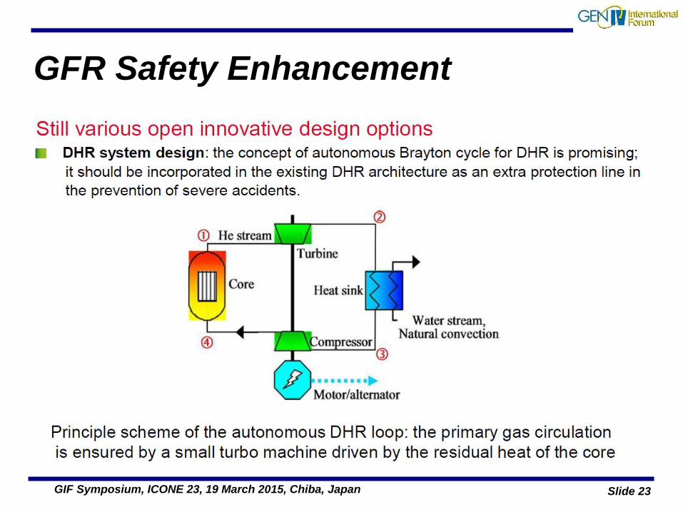
GIF Symposium, ICONE 23, 19 March 2015, Chiba, Japan
The Gas Cooled Fast Reactor (GFR)
Richard Stainsby on behalf of the GFR SSC National Nuclear Laboratory, UK (Euratom)
With contributions from:
Christian Poette (CEA)
Akos Horvath, MTA-EK, Hungary (Euratom)
Tatsuya Hinoki, Kyoto University, Japan
Slide 2 GIF Symposium, ICONE 23, 19 March 2015, Chiba, Japan
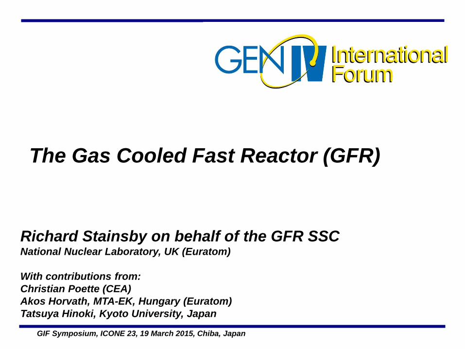
Motivation • Fast reactors are important for the sustainability of nuclear
power:
–More efficient use of fuel
–Reduced volumes, heat loading and radiotoxicity of high level waste
• Sodium cooled fast reactors are the shortest route to FR deployment, but:
–The sodium coolant has some undesirable features:
»Chemical incompatibility with air and water
»Difficult to carry out inspection and repair
»Avoiding sodium boiling places a restriction on achievable core outlet temperature
• Gas cooled fast reactors do not suffer from any of the above:
–Chemically inert, very stable nucleus, void coefficient is small (but positive), single phase coolant eliminates boiling and optically transparent.
Slide 3 GIF Symposium, ICONE 23, 19 March 2015, Chiba, Japan
Motivation
• But …
– Gaseous coolants have little thermal inertia ->
rapid heat-up of the core following loss of forced
cooling;
» Compounded by the lack of thermal inertia of
the core structure (no moderator) + high power
density
Slide 4 GIF Symposium, ICONE 23, 19 March 2015, Chiba, Japan
Advantages and Disadvantages of GFR
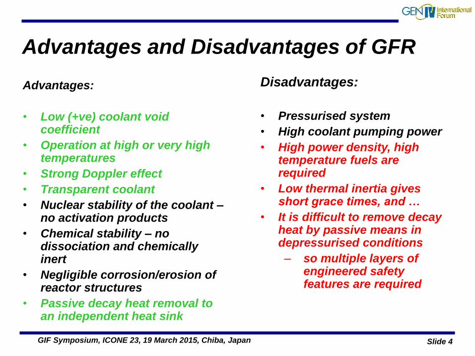
Advantages:
• Low (+ve) coolant void coefficient
• Operation at high or very high temperatures
• Strong Doppler effect
• Transparent coolant
• Nuclear stability of the coolant – no activation products
• Chemical stability – no dissociation and chemically inert
• Negligible corrosion/erosion of reactor structures
• Passive decay heat removal to an independent heat sink
Disadvantages:
• Pressurised system
• High coolant pumping power
• High power density, high temperature fuels are required
• Low thermal inertia gives short grace times, and …
• It is difficult to remove decay heat by passive means in depressurised conditions
– so multiple layers of engineered safety features are required
Slide 5 GIF Symposium, ICONE 23, 19 March 2015, Chiba, Japan
Gas cooled fast reactor concepts: a partial historical perspective
• US, General Atomics – The GCFR programme
–Started in the 1960’s
–Capitalised upon High Temperature (thermal) Reactor
(HTR) experience:
»Peach Bottom and Fort St Vrain
–Funded by US DOE
–Collaboration with European partners
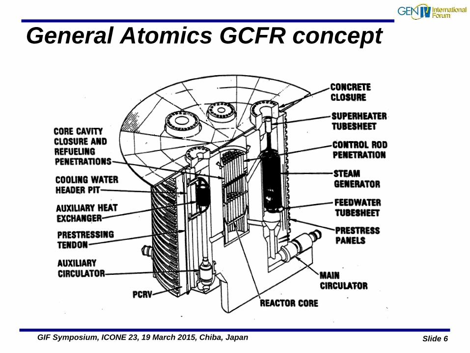
• Helium cooled reactor with a multi-cavity pre-stressed
concrete pressure vessel. Featured a vented fuel pin fuel
element design to reduce fuel clad stresses.
Slide 6 GIF Symposium, ICONE 23, 19 March 2015, Chiba, Japan
General Atomics GCFR concept
Slide 7 GIF Symposium, ICONE 23, 19 March 2015, Chiba, Japan
Germany: the Gas Breeder Memorandum
• Germany: the Gas Breeder Memorandum (1969)
–The German research centres at Karlsruhe and Jülich,
together with industrial partners,
–Defined three concepts, all cooled by helium,
–Fuel assemblies extrapolated from sodium cooled fast
reactors,
–Pre-stressed concrete pressure vessels
–Steam cycle,
–Some work was carried out on coated particle fuels and
direct cycle power cycles.
Slide 8 GIF Symposium, ICONE 23, 19 March 2015, Chiba, Japan
Europe: the Gas Breeder Reactor Association (1970 - 1981)
A number of organisations joined to form the Gas Breeder
Reactor Association. Four designs were developed:
• GBR-1, a 1000MWe helium cooled reactor with metallic clad
pin fuel
• GBR-2, 1000MWe reactor using coated particle fuel, slightly
elevated outlet temperature, helium coolant,
• GBR-3 1000MWe reactor using coated particle fuel, CO2
coolant
• GBR-4 design was developed to avoid complexities of the
particle bed fuel elements.
–Rib-roughened metal-clad fuel pins held in spacer grids.
Slide 9 GIF Symposium, ICONE 23, 19 March 2015, Chiba, Japan
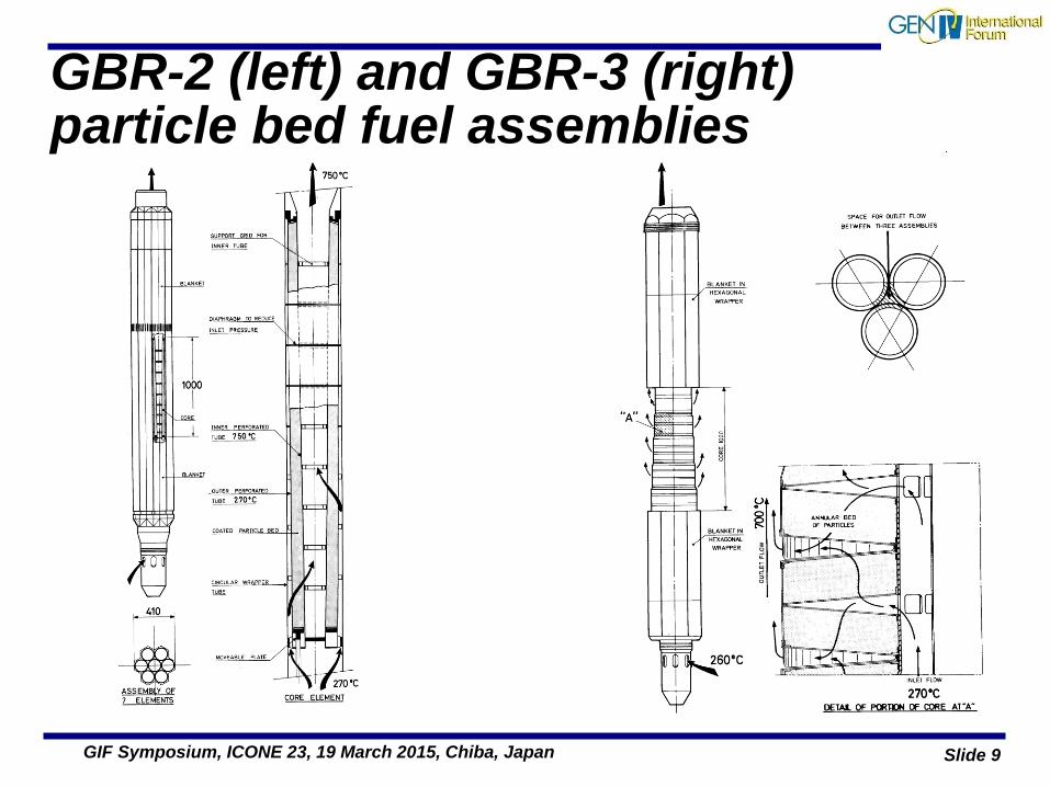
GBR-2 (left) and GBR-3 (right) particle bed fuel assemblies
Slide 10 GIF Symposium, ICONE 23, 19 March 2015, Chiba, Japan
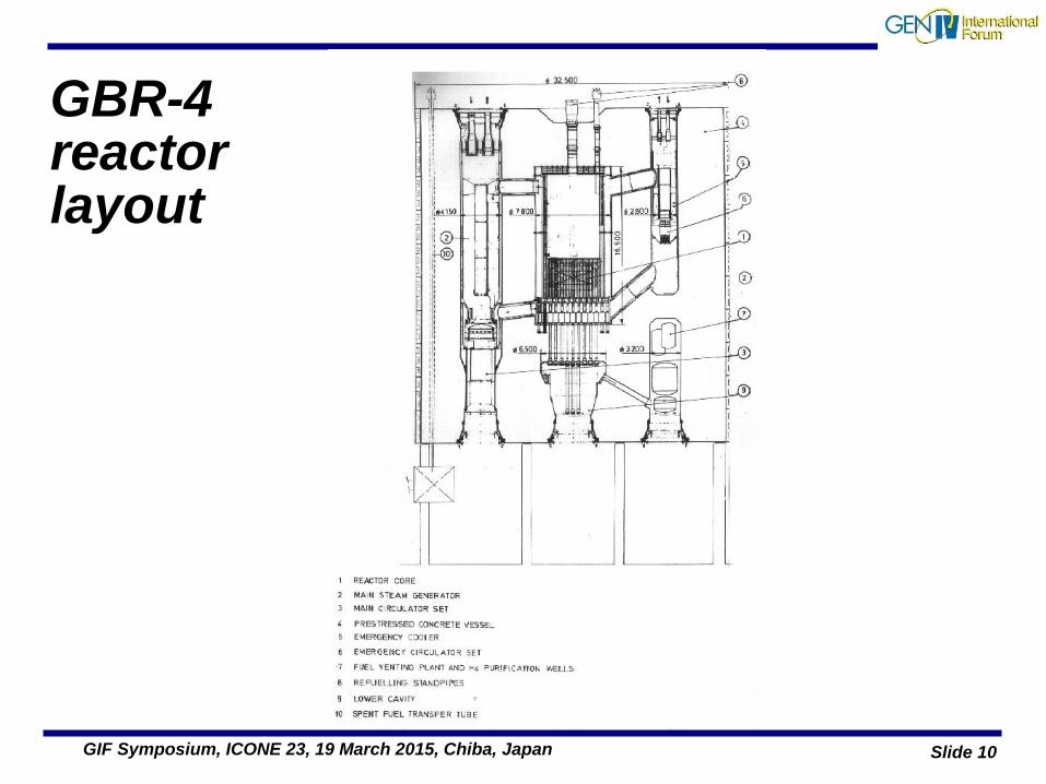
GBR-4 reactor layout
Slide 11 GIF Symposium, ICONE 23, 19 March 2015, Chiba, Japan
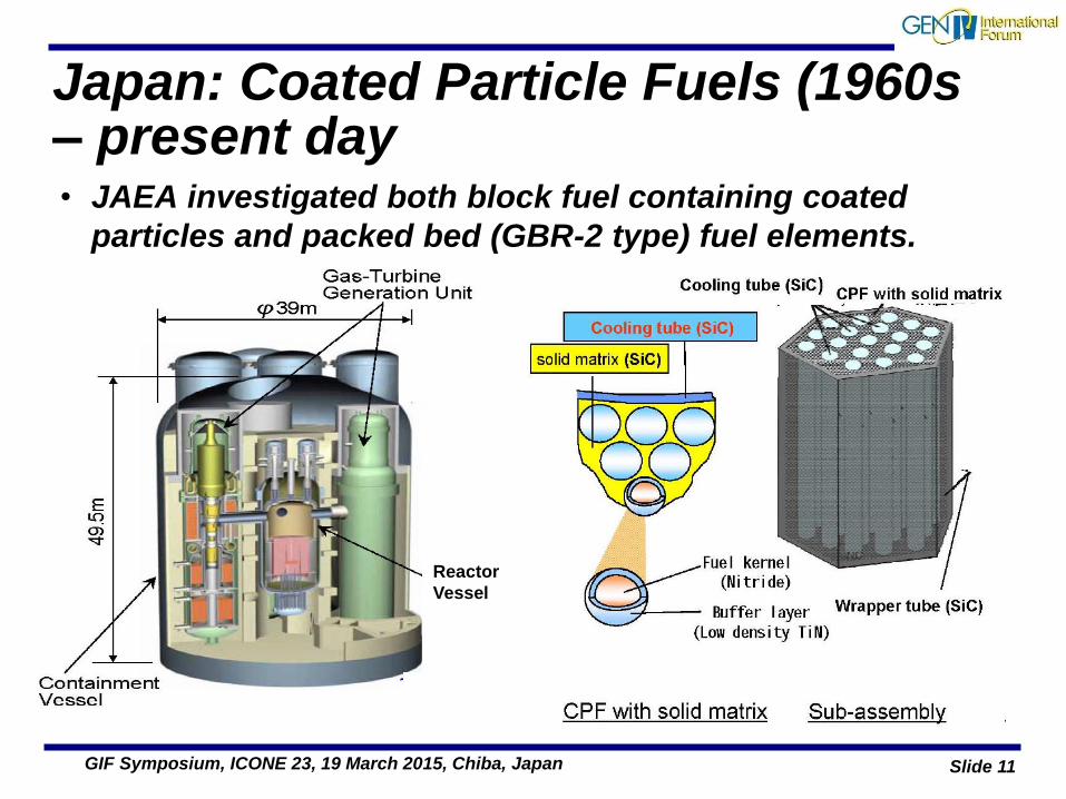
Japan: Coated Particle Fuels (1960s – present day • JAEA investigated both block fuel containing coated
particles and packed bed (GBR-2 type) fuel elements.
Reactor
Vessel
Slide 12 GIF Symposium, ICONE 23, 19 March 2015, Chiba, Japan
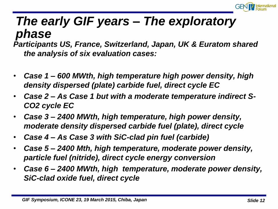
The early GIF years – The exploratory phase
Participants US, France, Switzerland, Japan, UK & Euratom shared
the analysis of six evaluation cases:
• Case 1 – 600 MWth, high temperature high power density, high
density dispersed (plate) carbide fuel, direct cycle EC
• Case 2 – As Case 1 but with a moderate temperature indirect S-
CO2 cycle EC
• Case 3 – 2400 MWth, high temperature, high power density,
moderate density dispersed carbide fuel (plate), direct cycle
• Case 4 – As Case 3 with SiC-clad pin fuel (carbide)
• Case 5 – 2400 Mth, high temperature, moderate power density,
particle fuel (nitride), direct cycle energy conversion
• Case 6 – 2400 MWth, high temperature, moderate power density,
SiC-clad oxide fuel, direct cycle
Slide 13 GIF Symposium, ICONE 23, 19 March 2015, Chiba, Japan
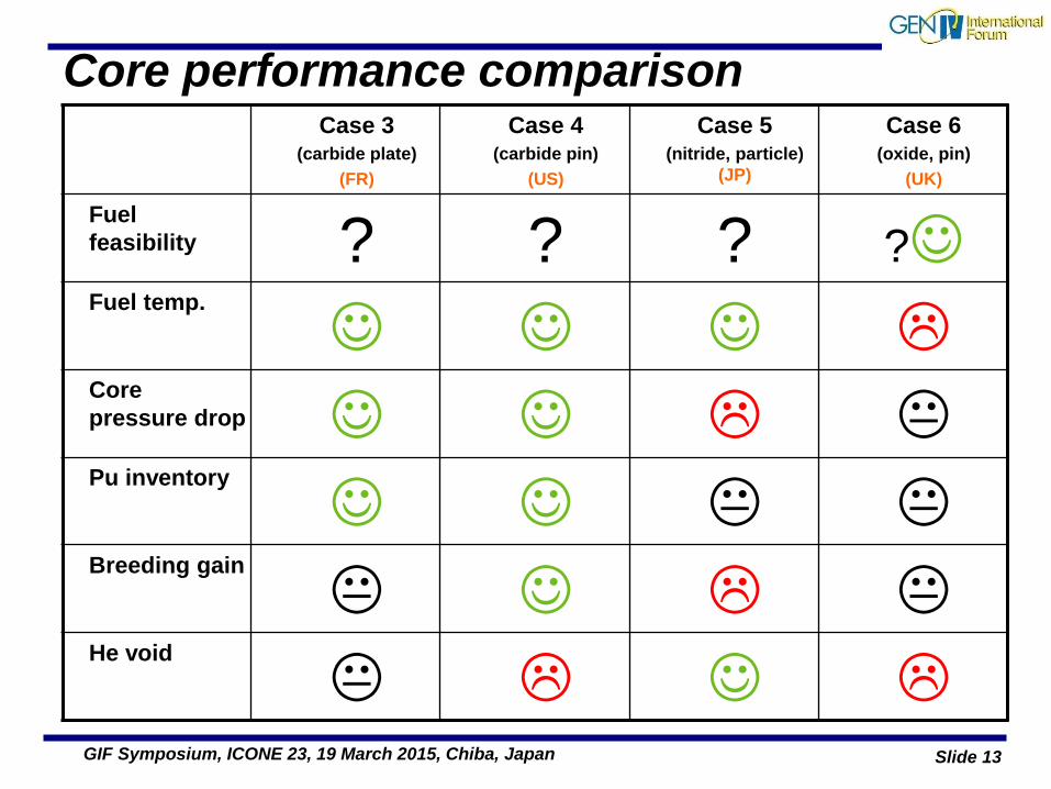
Case 3 (carbide plate)
(FR)
Case 4 (carbide pin)
(US)
Case 5 (nitride, particle)
(JP)
Case 6 (oxide, pin)
(UK)
Fuel
feasibility ? ? ? ? Fuel temp.
Core
pressure drop Pu inventory
Breeding gain
He void
Core performance comparison
Slide 14 GIF Symposium, ICONE 23, 19 March 2015, Chiba, Japan
Outcome of exploratory phase down-selection
• 600 MWth cores (Case 1 and Case 2) rejected on the basis of not
meeting breeding ratio ≥ 1.0 (without breeding blankets)
• At 2400 MWth, Case 5 (particle fuels) could not meet breeding
gain objective without the use of breeder blankets
• Case 3 was initially selected for study in the conceptual phase
as the reference, but the direct cycle option was soon dropped
in favour of an indirect helium-nitrogen Brayton / steam
combined cycle.
• CerCer plate fuel option was later dropped in favour of SiC-SiCf
ceramic matrix composite pin
Slide 15 GIF Symposium, ICONE 23, 19 March 2015, Chiba, Japan
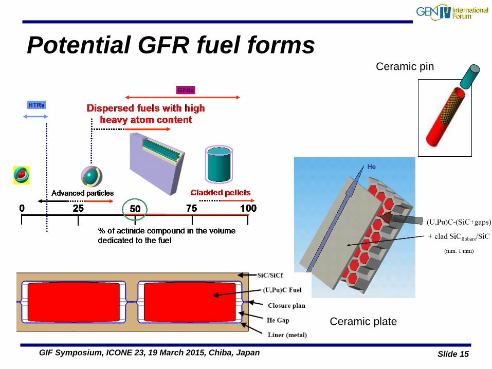
Potential GFR fuel forms
Ceramic plate
Ceramic pin
Slide 16 GIF Symposium, ICONE 23, 19 March 2015, Chiba, Japan
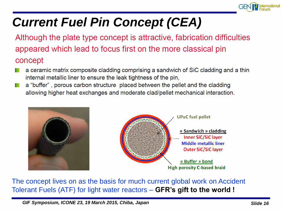
Current Fuel Pin Concept (CEA)
The concept lives on as the basis for much current global work on Accident
Tolerant Fuels (ATF) for light water reactors – GFR’s gift to the world !
Slide 17 GIF Symposium, ICONE 23, 19 March 2015, Chiba, Japan
… but work on coated particle fuels for GFR continues here in Japan …
Slide 18 GIF Symposium, ICONE 23, 19 March 2015, Chiba, Japan
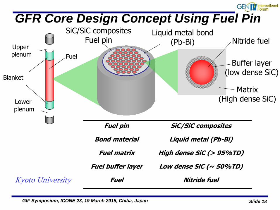
GFR Core Design Concept Using Fuel Pin
Fuel
Lower plenum
Blanket
SiC/SiC composites Fuel pin
Liquid metal bond (Pb-Bi) Nitride fuel
Buffer layer (low dense SiC)
Matrix (High dense SiC)
Fuel pin SiC/SiC composites
Bond material Liquid metal (Pb-Bi)
Fuel matrix High dense SiC (> 95%TD)
Fuel buffer layer Low dense SiC (~ 50%TD)
Fuel Nitride fuel Kyoto University
Upper plenum
Slide 19 GIF Symposium, ICONE 23, 19 March 2015, Chiba, Japan
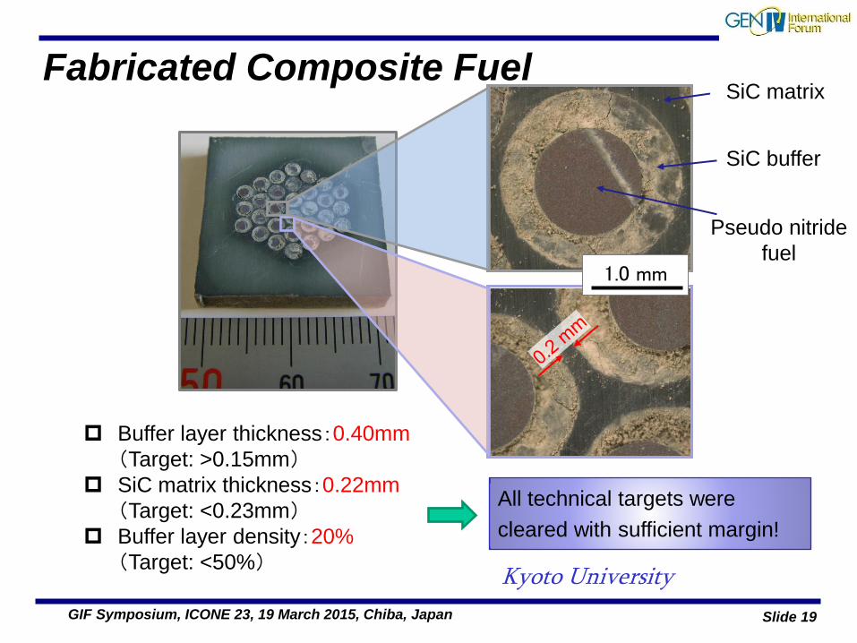
Fabricated Composite Fuel
Buffer layer thickness:0.40mm
(Target: >0.15mm)
SiC matrix thickness:0.22mm
(Target: <0.23mm)
Buffer layer density:20%
(Target: <50%)
All technical targets were
cleared with sufficient margin!
1.0 mm
SiC matrix
SiC buffer
Pseudo nitride
fuel
Kyoto University
Slide 20 GIF Symposium, ICONE 23, 19 March 2015, Chiba, Japan
GFR Fuel – the future (or possible futures)
• The “sandwich clad” fuel pin design appears to be viable
• Work has been done on non-active thermal testing and irradiating the individual components.
• Next steps are:
– To demonstrate end-cap sealing
– To produce rodlets
– To irradiate rodlets and to carry out PIE
• It would be good if advantage could be taken from parallel work on accident tolerant fuels for light water reactors.
• Coated particle fuels look like a good alternative but we would need to drop the proliferation resistance objective of having no breeder blankets
– Is it possible to retain PR objective with breeder blankets by spiking the these with minor actinides ?
Slide 21 GIF Symposium, ICONE 23, 19 March 2015, Chiba, Japan
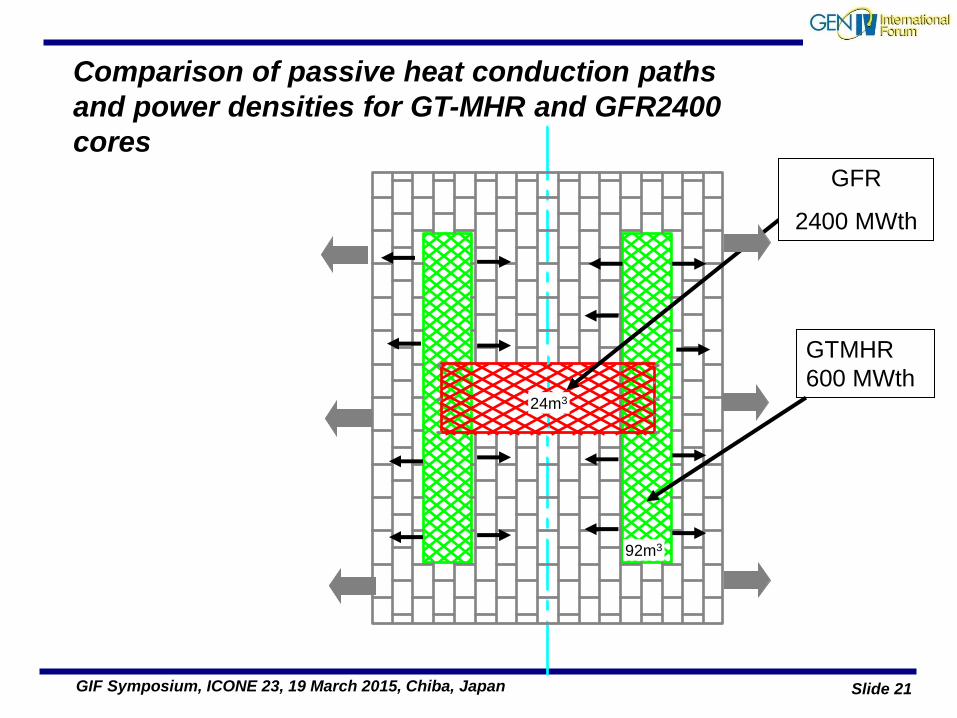
92m3
GTMHR
600 MWth
GFR
2400 MWth
24m3
Comparison of passive heat conduction paths
and power densities for GT-MHR and GFR2400
cores
Slide 22 GIF Symposium, ICONE 23, 19 March 2015, Chiba, Japan
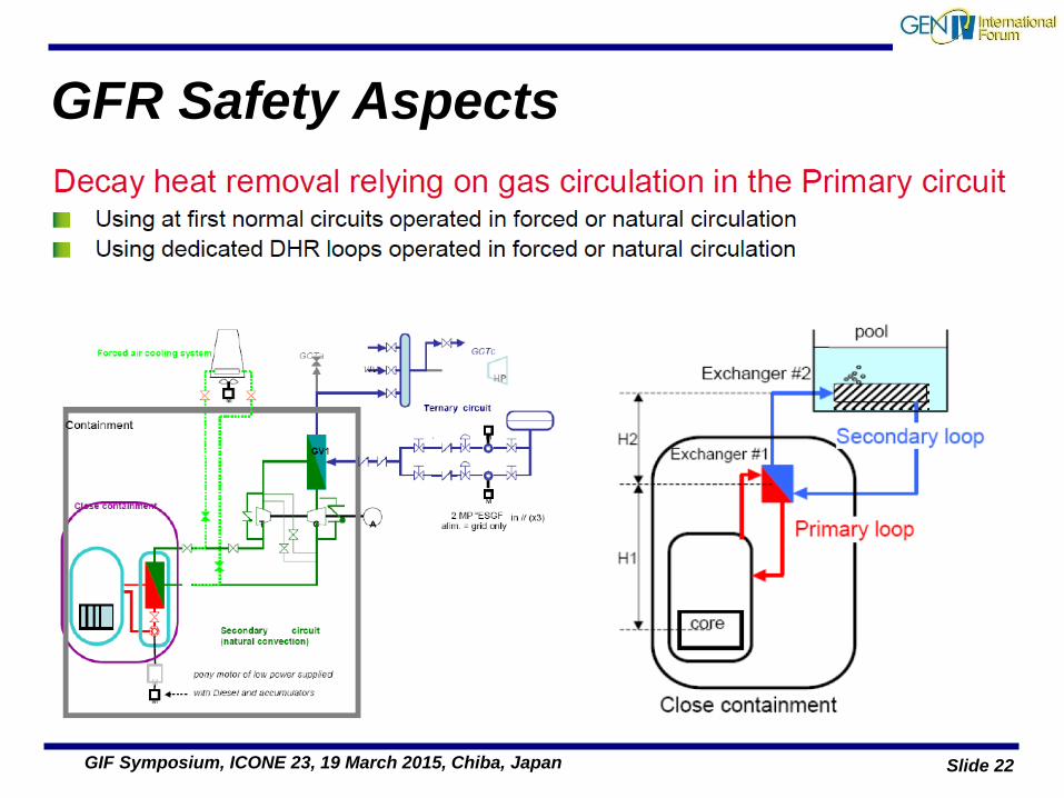
GFR Safety Aspects
Slide 23 GIF Symposium, ICONE 23, 19 March 2015, Chiba, Japan
GFR Safety Enhancement
Slide 24 GIF Symposium, ICONE 23, 19 March 2015, Chiba, Japan
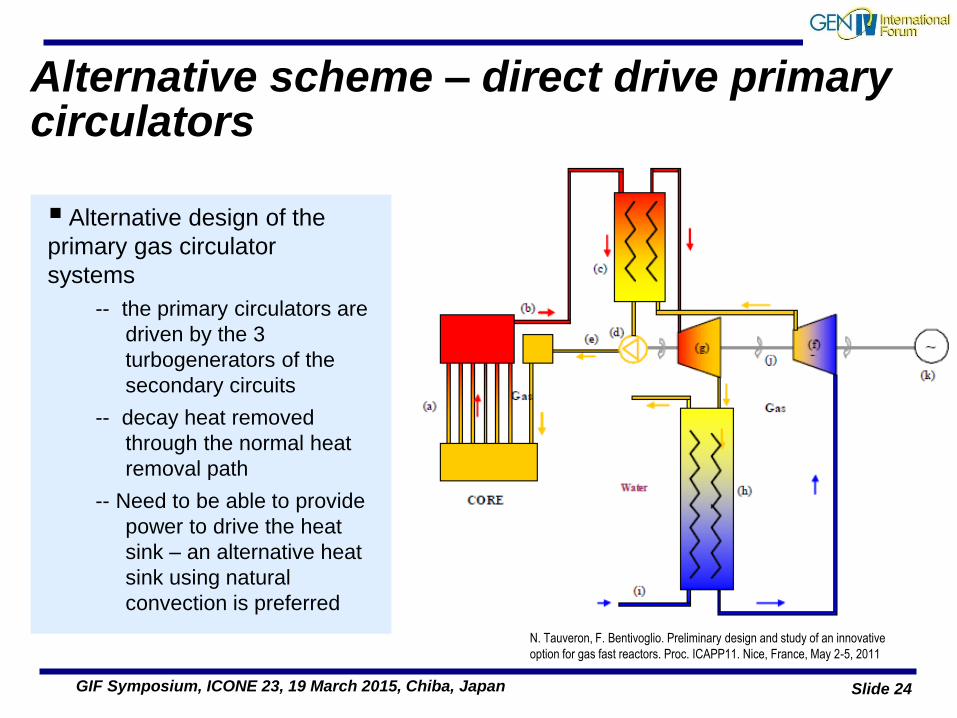
Alternative scheme – direct drive primary circulators
Alternative design of the
primary gas circulator
systems
-- the primary circulators are
driven by the 3
turbogenerators of the
secondary circuits
-- decay heat removed
through the normal heat
removal path
-- Need to be able to provide
power to drive the heat
sink – an alternative heat
sink using natural
convection is preferred
N. Tauveron, F. Bentivoglio. Preliminary design and study of an innovative
option for gas fast reactors. Proc. ICAPP11. Nice, France, May 2-5, 2011
Slide 25 GIF Symposium, ICONE 23, 19 March 2015, Chiba, Japan
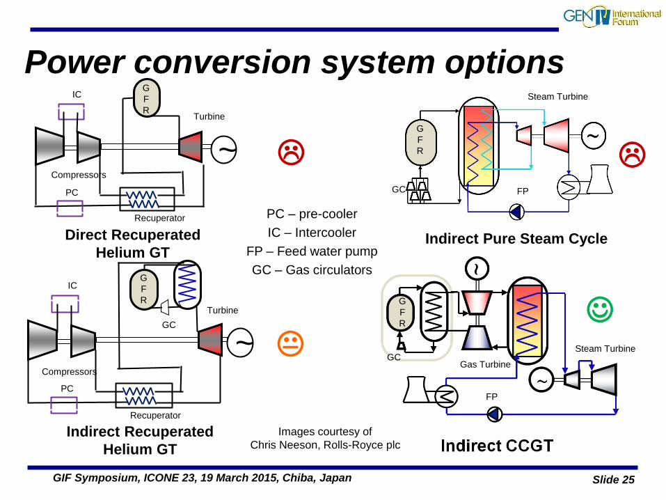
Power conversion system options
~
Direct Recuperated
Helium GT
~
G
F
R
G
F
R
G
F
R
Indirect Recuperated
Helium GT
G
F
R
Indirect Pure Steam Cycle
PC
PC
IC
IC
Turbine
Turbine
Steam Turbine
Steam Turbine
Gas Turbine
Compressors
Compressors
FP
FP
PC – pre-cooler
IC – Intercooler
FP – Feed water pump
GC – Gas circulators
GC
GC
GC
Recuperator
Recuperator
Images courtesy of
Chris Neeson, Rolls-Royce plc
Slide 26 GIF Symposium, ICONE 23, 19 March 2015, Chiba, Japan
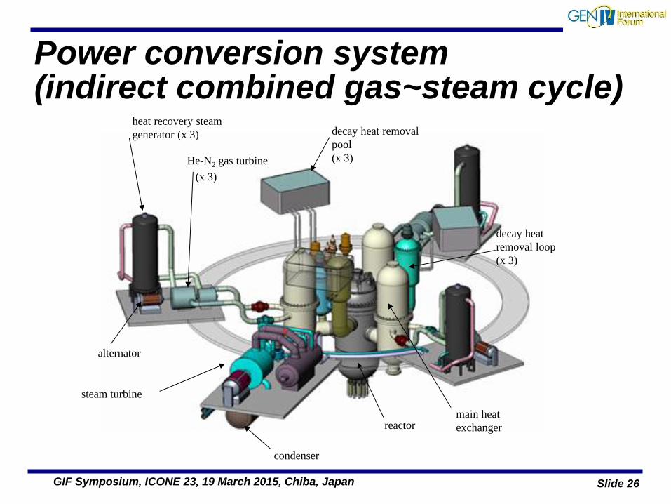
Power conversion system (indirect combined gas~steam cycle)
He-N2 gas turbine
(x 3)
heat recovery steam
generator (x 3)
alternator
steam turbine
condenser
decay heat removal
pool
(x 3)
reactor
decay heat
removal loop
(x 3)
main heat
exchanger
Slide 27 GIF Symposium, ICONE 23, 19 March 2015, Chiba, Japan
Status of GFR System Cooperation
GFR System Arrangement signed by Euratom, France, Switzerland and Japan
• France – very limited effort which has been dedicated to supporting the V4 ALLEGRO consortium
• Switzerland – No national funding for GFR R&D
• Japan – No national funding for GFR R&D and efforts re-directed post-Fukushima, but Kyoto University is contributing to fuel development.
• Euratom: FP7 GoFastR project ended in February 2013: – Work surrounding establishment of ALLEGRO in the FP7 ALLIANCE project. Minor
physics tasks in FP7 ESNII+,
– There was a poor match between first call for in the Horizon 2020 programme and the needs of GFR
» Next Horizon 2020 call will be published at the end of 2015 for projects starting in 2017
Slide 28 GIF Symposium, ICONE 23, 19 March 2015, Chiba, Japan
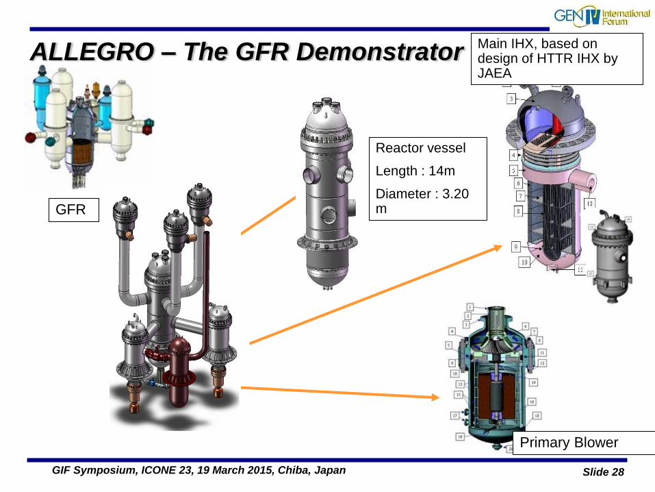
ALLEGRO – The GFR Demonstrator
Reactor vessel
Length : 14m
Diameter : 3.20 m
Main IHX, based on design of HTTR IHX by JAEA
GFR
Primary Blower
Slide 29 GIF Symposium, ICONE 23, 19 March 2015, Chiba, Japan
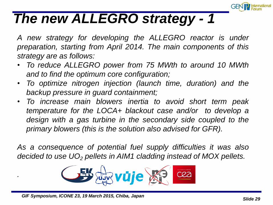
The new ALLEGRO strategy - 1
A new strategy for developing the ALLEGRO reactor is under
preparation, starting from April 2014. The main components of this
strategy are as follows:
• To reduce ALLEGRO power from 75 MWth to around 10 MWth
and to find the optimum core configuration;
• To optimize nitrogen injection (launch time, duration) and the
backup pressure in guard containment;
• To increase main blowers inertia to avoid short term peak
temperature for the LOCA+ blackout case and/or to develop a
design with a gas turbine in the secondary side coupled to the
primary blowers (this is the solution also advised for GFR).
As a consequence of potential fuel supply difficulties it was also
decided to use UO2 pellets in AIM1 cladding instead of MOX pellets.
.
Slide 30 GIF Symposium, ICONE 23, 19 March 2015, Chiba, Japan
The new ALLEGRO strategy - 2
•Ideas on high temperature remained unchanged.
•The design should ensure the possibility of increasing reactor power
(eventually up to 75 MWth) if safety considerations allow for it.
•The initial core (UO2 / AIM1) will be replaced by ceramic clad fuel
whenever the development and qualification of this fuel will have been
completed.
•A new system Roadmap is under preparation to cover all design,
safety and experimental aspects of ALLEGRO development.
Slide 31 GIF Symposium, ICONE 23, 19 March 2015, Chiba, Japan
Conclusions • The GFR concept is not new, having been explored by a number
of countries since the 1960’s
• GFR can be considered as a longer term fast reactor concept that
will provide an equivalent of VHTR that can sustain a self-
sustaining closed fuel cycle.
• Progress in the early days of the GIF was good with six partners
all contributing to the exploratory phase.
• Formal signing of the system arrangement reduced the number of
partners to four, and effort has continued to decrease to to a
shifting of priorities back to SFR, and a refocusing of R&D funding
following the Fukushima accident.
• Viable concepts for fuel and cladding have been developed.
• Work remains to be done on refining the safety architecture such
that the safety goals can be met in a cost effective manner.
Slide 32 GIF Symposium, ICONE 23, 19 March 2015, Chiba, Japan
Conclusions (2)
• Work continues in the V4G4 consortium on developing ALLEGRO to be a GFR demonstrator – funded at a fairly low level by the European Commission and the Governments of the V4 member states.
• ALLEGRO concept has been re-worked to start with a much smaller core 10MWth c.f. 75MWth, starting with UO2 fuel as opposed to MOX
• There are synergies with the VHTR system that can be exploited if the GFR partners can get funding to collaborate, such as:
– Pressure boundary materials and design,
– Main heat exchangers and power conversion
– Oil-free gas circulators and other helium circuit components.
• The future of the GFR system itself depends upon the will of the signatories to continue – whether this will remains will be demonstrated in 2016 when the current System Arrangement expires.
Slide 33 GIF Symposium, ICONE 23, 19 March 2015, Chiba, Japan
Acknowledgements I would like to acknowledge the support of the members of the GFR Sytem
Steering Committee and CDS & FCM PMBs both present and past:
• Present SSC members
– Konstantin Mikityuk (PSI), Alfredo Vasile (CEA), Koji Sato (JAEA), Akos Horvath (MTA_EK), Henri Paillere (Secretariat)
• GFR SSC - EG Liaison: Frank Carre
• Past SSC Chairs:
– Kevan Weaver (INL), Jaques Roualt (CEA), Pascal Anzieu (CEA)
• And many more …
– Christian Poette, Philipe Guedeney, Nathalie Chauvin, Jean-Claude Garnier, Emmanuel Touron, Tatsuya Hinoki, Tomoyasu Mizuno, Manuel Pouchon, Joe Somers, Colin Mitchell, Paul Coddington, Tom Wei, Sylvie Aniel, Jean-Charles Roubin
• Apologies to all I have forgotten to mention and to those whose names for whom have forgotten the spelling !