Embed Size (px)
Citation preview

Transport Layer
The Future
Homework questionsgt The next test is coming the 19th (just
before turkey day) Wednesday = review + anything not
done today Friday will cover threaded Java
programming
3-1
Transport Layer 3-2
Chapter 3Transport Layer
Computer Networking A Top Down Approach 4th edition Jim Kurose Keith RossAddison-Wesley July 2007
A note on the use of these ppt slidesWersquore making these slides freely available to all (faculty students readers) Theyrsquore in PowerPoint form so you can add modify and delete slides (including this one) and slide content to suit your needs They obviously represent a lot of work on our part In return for use we only ask the following If you use these slides (eg in a class) in substantially unaltered form
that you mention their source (after all wersquod like people to use our book) If you post any slides in substantially unaltered form on a www site that
you note that they are adapted from (or perhaps identical to) our slides and note our copyright of this material
Thanks and enjoy JFKKWR
All material copyright 1996-2007JF Kurose and KW Ross All Rights Reserved
Transport Layer 3-3
TCP ACK generation [RFC 1122 RFC 2581]
Event at Receiver
Arrival of in-order segment withexpected seq All data up toexpected seq already ACKed
Arrival of in-order segment withexpected seq One other segment has ACK pending
Arrival of out-of-order segmenthigher-than-expect seq Gap detected
Arrival of segment that partially or completely fills gap
TCP Receiver action
Delayed ACK Wait up to 500msfor next segment If no next segmentsend ACK
Immediately send single cumulative ACK ACKing both in-order segments
Immediately send duplicate ACK indicating seq of next expected byte
Immediate send ACK provided thatsegment startsat lower end of gap
Transport Layer 3-4
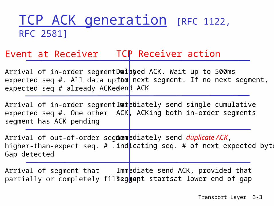
Fast Retransmit
Time-out period often relatively long long delay before resending lost packet
Detect lost segments via duplicate ACKs Sender often sends many segments back-to-back If segment is lost there will likely be many duplicate
ACKs
If sender receives 3 ACKs for the same data it supposes that segment after ACKed data was lost fast retransmit resend
segment before timer expires
Transport Layer 3-5
event ACK received with ACK field value of y if (y gt SendBase) SendBase = y if (there are currently not-yet-acknowledged segments) start timer else increment count of dup ACKs received for y if (count of dup ACKs received for y = 3) resend segment with sequence number y
Fast retransmit algorithm
a duplicate ACK for already ACKed segment
fast retransmit
Transport Layer 3-6
Chapter 3 outline
31 Transport-layer services 32 Multiplexing and demultiplexing 33 Connectionless transport UDP 34 Principles of reliable data transfer
35 Connection-oriented transport TCP segment structure reliable data transfer flow control connection
management 36 Principles of
congestion control 37 TCP congestion
control
Transport Layer 3-7
TCP Flow Control
receive side of TCP connection has a receive buffer
speed-matching service matching the send rate to the receiving apprsquos drain rate app process may be
slow at reading from buffer
sender wonrsquot overflow
receiverrsquos buffer bytransmitting too
much too fast
flow control
Transport Layer 3-8
TCP Flow control how it works
(Suppose TCP receiver discards out-of-order segments)
spare room in buffer= RcvWindow= RcvBuffer-[LastByteRcvd -
LastByteRead]
Rcvr advertises spare room by including value of RcvWindow in segments
Sender limits unACKed data to RcvWindow guarantees receive
buffer doesnrsquot overflow
Transport Layer 3-9
Chapter 3 outline
31 Transport-layer services 32 Multiplexing and demultiplexing 33 Connectionless transport UDP 34 Principles of reliable data transfer
35 Connection-oriented transport TCP segment structure reliable data transfer flow control connection
management 36 Principles of
congestion control 37 TCP congestion
control
Transport Layer 3-10
TCP Connection Management
Recall TCP sender receiver establish ldquoconnectionrdquo before exchanging data segments
initialize TCP variables seq s buffers flow control
info (eg RcvWindow) client connection
initiator Socket clientSocket = new
Socket(hostnameport
number) server contacted by
client Socket connectionSocket =
welcomeSocketaccept()
Three way handshake
Step 1 client host sends TCP SYN segment to server specifies initial seq no data
Step 2 server host receives SYN replies with SYNACK segment server allocates buffers specifies server initial
seq Step 3 client receives
SYNACK replies with ACK segment which may contain data
Transport Layer 3-11
TCP Connection Management (cont)
Closing a connection
client closes socket clientSocketclose()
Step 1 client end system sends TCP FIN control segment to server
Step 2 server receives FIN replies with ACK Closes connection sends FIN
client
FIN
server
ACK
ACK
FIN
close
close
closed
tim
ed w
ait
Transport Layer 3-12
TCP Connection Management (cont)
Step 3 client receives FIN replies with ACK
Enters ldquotimed waitrdquo - will respond with ACK to received FINs
Step 4 server receives ACK Connection closed
Note with small modification can handle simultaneous FINs
client
FIN
server
ACK
ACK
FIN
closing
closing
closed
tim
ed w
ait
closed
Transport Layer 3-13
TCP Connection Management (cont)
TCP clientlifecycle
TCP serverlifecycle
Transport Layer 3-14
Chapter 3 outline
31 Transport-layer services 32 Multiplexing and demultiplexing 33 Connectionless transport UDP 34 Principles of reliable data transfer
35 Connection-oriented transport TCP segment structure reliable data transfer flow control connection
management 36 Principles of
congestion control 37 TCP congestion
control
Transport Layer 3-15
Principles of Congestion Control
Congestion informally ldquotoo many sources sending too
much data too fast for network to handlerdquo different from flow control manifestations
lost packets (buffer overflow at routers) long delays (queueing in router buffers)
a top-10 problem
Transport Layer 3-16
Causescosts of congestion scenario 1
two senders two receivers
one router infinite buffers
no retransmission
large delays when congested
maximum achievable throughput
unlimited shared output link buffers
Host Alin original data
Host B
lout
Transport Layer 3-17
Causescosts of congestion scenario 2
one router finite buffers sender retransmission of lost packet
finite shared output link buffers
Host A lin original data
Host B
lout
lin original data plus retransmitted data
Transport Layer 3-18
Causescosts of congestion scenario 2 always (goodput)
ldquoperfectrdquo retransmission only when loss
retransmission of delayed (not lost) packet makes
larger (than perfect case) for same
lin
lout
=
lin
lout
gtl
inl
out
ldquocostsrdquo of congestion more work (retrans) for given ldquogoodputrdquo unneeded retransmissions link carries multiple copies of
pkt
R2
R2lin
l ou
t
b
R2
R2lin
l ou
t
a
R2
R2lin
l ou
t
c
R4
R3
Transport Layer 3-19
Causescosts of congestion scenario 3 four senders multihop paths timeoutretransmit
lin
Q what happens as and increase
lin
finite shared output link buffers
Host Alin original data
Host B
lout
lin original data plus retransmitted data
Transport Layer 3-20
Causescosts of congestion scenario 3
Another ldquocostrdquo of congestion when packet dropped any ldquoupstream
transmission capacity used for that packet was wasted
Host A
Host B
lo
u
t
Transport Layer 3-21
Approaches towards congestion control
End-end congestion control
no explicit feedback from network
congestion inferred from end-system observed loss delay
approach taken by TCP
Network-assisted congestion control
routers provide feedback to end systems single bit indicating
congestion (SNA DECbit TCPIP ECN ATM)
explicit rate sender should send at
Two broad approaches towards congestion control
Transport Layer 3-22
Case study ATM ABR congestion control
ABR available bit rate
ldquoelastic servicerdquo if senderrsquos path
ldquounderloadedrdquo sender should use
available bandwidth if senderrsquos path
congested sender throttled to
minimum guaranteed rate
RM (resource management) cells
sent by sender interspersed with data cells
bits in RM cell set by switches (ldquonetwork-assistedrdquo) NI bit no increase in rate
(mild congestion) CI bit congestion
indication RM cells returned to sender
by receiver with bits intact
Transport Layer 3-23
Case study ATM ABR congestion control
two-byte ER (explicit rate) field in RM cell congested switch may lower ER value in cell senderrsquo send rate thus maximum supportable rate on
path EFCI bit in data cells set to 1 in congested
switch if data cell preceding RM cell has EFCI set sender sets
CI bit in returned RM cell
Transport Layer 3-24
Chapter 3 outline
31 Transport-layer services 32 Multiplexing and demultiplexing 33 Connectionless transport UDP 34 Principles of reliable data transfer
35 Connection-oriented transport TCP segment structure reliable data transfer flow control connection
management 36 Principles of
congestion control 37 TCP congestion
control
Transport Layer 3-25
TCP congestion control additive increase multiplicative decrease
8 Kbytes
16 Kbytes
24 Kbytes
time
congestionwindow
Approach increase transmission rate (window size) probing for usable bandwidth until loss occurs additive increase increase CongWin by 1
MSS every RTT until loss detected multiplicative decrease cut CongWin in half
after loss
timecong
estio
n w
indo
w s
ize
Saw toothbehavior probing
for bandwidth
Transport Layer 3-26
TCP Congestion Control details
sender limits transmission LastByteSent-LastByteAcked CongWin Roughly
CongWin is dynamic function of perceived network congestion
How does sender perceive congestion
loss event = timeout or 3 duplicate acks
TCP sender reduces rate (CongWin) after loss event
three mechanisms AIMD slow start conservative after
timeout events
rate = CongWin
RTT Bytessec
Transport Layer 3-27
TCP Slow Start
When connection begins CongWin = 1 MSS Example MSS = 500
bytes amp RTT = 200 msec
initial rate = 20 kbps available bandwidth
may be gtgt MSSRTT desirable to quickly
ramp up to respectable rate
When connection begins increase rate exponentially fast until first loss event
Transport Layer 3-28
TCP Slow Start (more)
When connection begins increase rate exponentially until first loss event double CongWin every RTT done by incrementing CongWin for every ACK
received Summary initial rate is slow but ramps up
exponentially fast
Host A
one segment
RTT
Host B
time
two segments
four segments
Transport Layer 3-29
Refinement
Q When should the exponential increase switch to linear
A When CongWin gets to 12 of its value before timeout
Implementation Variable Threshold At loss event Threshold
is set to 12 of CongWin just before loss event
Transport Layer 3-30
Refinement inferring loss
After 3 dup ACKs CongWin is cut in half window then grows
linearly But after timeout event
CongWin instead set to 1 MSS
window then grows exponentially
to a threshold then grows linearly
3 dup ACKs indicates
network capable of delivering some segments
timeout indicates a ldquomore alarmingrdquo congestion scenario
Philosophy
Transport Layer 3-31
Summary TCP Congestion Control
When CongWin is below Threshold sender in slow-start phase window grows exponentially
When CongWin is above Threshold sender is in congestion-avoidance phase window grows linearly
When a triple duplicate ACK occurs Threshold set to CongWin2 and CongWin set to Threshold
When timeout occurs Threshold set to CongWin2 and CongWin is set to 1 MSS
Transport Layer 3-32
TCP sender congestion control
State Event TCP Sender Action Commentary
Slow Start (SS)
ACK receipt for previously unacked data
CongWin = CongWin + MSS If (CongWin gt Threshold) set state to ldquoCongestion Avoidancerdquo
Resulting in a doubling of CongWin every RTT
CongestionAvoidance (CA)
ACK receipt for previously unacked data
CongWin = CongWin+MSS (MSSCongWin)
Additive increase resulting in increase of CongWin by 1 MSS every RTT
SS or CA Loss event detected by triple duplicate ACK
Threshold = CongWin2 CongWin = ThresholdSet state to ldquoCongestion Avoidancerdquo
Fast recovery implementing multiplicative decrease CongWin will not drop below 1 MSS
SS or CA Timeout Threshold = CongWin2 CongWin = 1 MSSSet state to ldquoSlow Startrdquo
Enter slow start
SS or CA Duplicate ACK
Increment duplicate ACK count for segment being acked
CongWin and Threshold not changed
Transport Layer 3-33
TCP throughput
Whatrsquos the average throughout of TCP as a function of window size and RTT Ignore slow start
Let W be the window size when loss occurs
When window is W throughput is WRTT Just after loss window drops to W2
throughput to W2RTT Average throughout 75 WRTT
Transport Layer 3-34
TCP Futures TCP over ldquolong fat pipesrdquo
Example 1500 byte segments 100ms RTT want 10 Gbps throughput
Requires window size W = 83333 in-flight segments
Throughput in terms of loss rate
L = 210-10 Wow New versions of TCP for high-speed
LRTT
MSS221
Transport Layer 3-35
Fairness goal if K TCP sessions share same bottleneck link of bandwidth R each should have average rate of RK
TCP connection 1
bottleneckrouter
capacity R
TCP connection 2
TCP Fairness
Transport Layer 3-36
Why is TCP fair
Two competing sessions Additive increase gives slope of 1 as throughout increases multiplicative decrease decreases throughput proportionally
R
R
equal bandwidth share
Connection 1 throughputConnect
ion 2
th
roughput
congestion avoidance additive increaseloss decrease window by factor of 2
congestion avoidance additive increaseloss decrease window by factor of 2
Transport Layer 3-37
Fairness (more)
Fairness and UDP Multimedia apps
often do not use TCP do not want rate
throttled by congestion control
Instead use UDP pump audiovideo at
constant rate tolerate packet loss
Research area TCP friendly
Fairness and parallel TCP connections
nothing prevents app from opening parallel connections between 2 hosts
Web browsers do this Example link of rate R
supporting 9 connections new app asks for 1 TCP
gets rate R10 new app asks for 11 TCPs
gets R2
Transport Layer 3-38
Chapter 3 Summary principles behind
transport layer services multiplexing
demultiplexing reliable data transfer flow control congestion control
instantiation and implementation in the Internet UDP TCP
Next leaving the
network ldquoedgerdquo (application transport layers)
into the network ldquocorerdquo

Transport Layer 3-2
Chapter 3Transport Layer
Computer Networking A Top Down Approach 4th edition Jim Kurose Keith RossAddison-Wesley July 2007
A note on the use of these ppt slidesWersquore making these slides freely available to all (faculty students readers) Theyrsquore in PowerPoint form so you can add modify and delete slides (including this one) and slide content to suit your needs They obviously represent a lot of work on our part In return for use we only ask the following If you use these slides (eg in a class) in substantially unaltered form
that you mention their source (after all wersquod like people to use our book) If you post any slides in substantially unaltered form on a www site that
you note that they are adapted from (or perhaps identical to) our slides and note our copyright of this material
Thanks and enjoy JFKKWR
All material copyright 1996-2007JF Kurose and KW Ross All Rights Reserved
Transport Layer 3-3
TCP ACK generation [RFC 1122 RFC 2581]
Event at Receiver
Arrival of in-order segment withexpected seq All data up toexpected seq already ACKed
Arrival of in-order segment withexpected seq One other segment has ACK pending
Arrival of out-of-order segmenthigher-than-expect seq Gap detected
Arrival of segment that partially or completely fills gap
TCP Receiver action
Delayed ACK Wait up to 500msfor next segment If no next segmentsend ACK
Immediately send single cumulative ACK ACKing both in-order segments
Immediately send duplicate ACK indicating seq of next expected byte
Immediate send ACK provided thatsegment startsat lower end of gap
Transport Layer 3-4
Fast Retransmit
Time-out period often relatively long long delay before resending lost packet
Detect lost segments via duplicate ACKs Sender often sends many segments back-to-back If segment is lost there will likely be many duplicate
ACKs
If sender receives 3 ACKs for the same data it supposes that segment after ACKed data was lost fast retransmit resend
segment before timer expires
Transport Layer 3-5
event ACK received with ACK field value of y if (y gt SendBase) SendBase = y if (there are currently not-yet-acknowledged segments) start timer else increment count of dup ACKs received for y if (count of dup ACKs received for y = 3) resend segment with sequence number y
Fast retransmit algorithm
a duplicate ACK for already ACKed segment
fast retransmit
Transport Layer 3-6
Chapter 3 outline
31 Transport-layer services 32 Multiplexing and demultiplexing 33 Connectionless transport UDP 34 Principles of reliable data transfer
35 Connection-oriented transport TCP segment structure reliable data transfer flow control connection
management 36 Principles of
congestion control 37 TCP congestion
control
Transport Layer 3-7
TCP Flow Control
receive side of TCP connection has a receive buffer
speed-matching service matching the send rate to the receiving apprsquos drain rate app process may be
slow at reading from buffer
sender wonrsquot overflow
receiverrsquos buffer bytransmitting too
much too fast
flow control
Transport Layer 3-8
TCP Flow control how it works
(Suppose TCP receiver discards out-of-order segments)
spare room in buffer= RcvWindow= RcvBuffer-[LastByteRcvd -
LastByteRead]
Rcvr advertises spare room by including value of RcvWindow in segments
Sender limits unACKed data to RcvWindow guarantees receive
buffer doesnrsquot overflow
Transport Layer 3-9
Chapter 3 outline
31 Transport-layer services 32 Multiplexing and demultiplexing 33 Connectionless transport UDP 34 Principles of reliable data transfer
35 Connection-oriented transport TCP segment structure reliable data transfer flow control connection
management 36 Principles of
congestion control 37 TCP congestion
control
Transport Layer 3-10
TCP Connection Management
Recall TCP sender receiver establish ldquoconnectionrdquo before exchanging data segments
initialize TCP variables seq s buffers flow control
info (eg RcvWindow) client connection
initiator Socket clientSocket = new
Socket(hostnameport
number) server contacted by
client Socket connectionSocket =
welcomeSocketaccept()
Three way handshake
Step 1 client host sends TCP SYN segment to server specifies initial seq no data
Step 2 server host receives SYN replies with SYNACK segment server allocates buffers specifies server initial
seq Step 3 client receives
SYNACK replies with ACK segment which may contain data
Transport Layer 3-11
TCP Connection Management (cont)
Closing a connection
client closes socket clientSocketclose()
Step 1 client end system sends TCP FIN control segment to server
Step 2 server receives FIN replies with ACK Closes connection sends FIN
client
FIN
server
ACK
ACK
FIN
close
close
closed
tim
ed w
ait
Transport Layer 3-12
TCP Connection Management (cont)
Step 3 client receives FIN replies with ACK
Enters ldquotimed waitrdquo - will respond with ACK to received FINs
Step 4 server receives ACK Connection closed
Note with small modification can handle simultaneous FINs
client
FIN
server
ACK
ACK
FIN
closing
closing
closed
tim
ed w
ait
closed
Transport Layer 3-13
TCP Connection Management (cont)
TCP clientlifecycle
TCP serverlifecycle
Transport Layer 3-14
Chapter 3 outline
31 Transport-layer services 32 Multiplexing and demultiplexing 33 Connectionless transport UDP 34 Principles of reliable data transfer
35 Connection-oriented transport TCP segment structure reliable data transfer flow control connection
management 36 Principles of
congestion control 37 TCP congestion
control
Transport Layer 3-15
Principles of Congestion Control
Congestion informally ldquotoo many sources sending too
much data too fast for network to handlerdquo different from flow control manifestations
lost packets (buffer overflow at routers) long delays (queueing in router buffers)
a top-10 problem
Transport Layer 3-16
Causescosts of congestion scenario 1
two senders two receivers
one router infinite buffers
no retransmission
large delays when congested
maximum achievable throughput
unlimited shared output link buffers
Host Alin original data
Host B
lout
Transport Layer 3-17
Causescosts of congestion scenario 2
one router finite buffers sender retransmission of lost packet
finite shared output link buffers
Host A lin original data
Host B
lout
lin original data plus retransmitted data
Transport Layer 3-18
Causescosts of congestion scenario 2 always (goodput)
ldquoperfectrdquo retransmission only when loss
retransmission of delayed (not lost) packet makes
larger (than perfect case) for same
lin
lout
=
lin
lout
gtl
inl
out
ldquocostsrdquo of congestion more work (retrans) for given ldquogoodputrdquo unneeded retransmissions link carries multiple copies of
pkt
R2
R2lin
l ou
t
b
R2
R2lin
l ou
t
a
R2
R2lin
l ou
t
c
R4
R3
Transport Layer 3-19
Causescosts of congestion scenario 3 four senders multihop paths timeoutretransmit
lin
Q what happens as and increase
lin
finite shared output link buffers
Host Alin original data
Host B
lout
lin original data plus retransmitted data
Transport Layer 3-20
Causescosts of congestion scenario 3
Another ldquocostrdquo of congestion when packet dropped any ldquoupstream
transmission capacity used for that packet was wasted
Host A
Host B
lo
u
t
Transport Layer 3-21
Approaches towards congestion control
End-end congestion control
no explicit feedback from network
congestion inferred from end-system observed loss delay
approach taken by TCP
Network-assisted congestion control
routers provide feedback to end systems single bit indicating
congestion (SNA DECbit TCPIP ECN ATM)
explicit rate sender should send at
Two broad approaches towards congestion control
Transport Layer 3-22
Case study ATM ABR congestion control
ABR available bit rate
ldquoelastic servicerdquo if senderrsquos path
ldquounderloadedrdquo sender should use
available bandwidth if senderrsquos path
congested sender throttled to
minimum guaranteed rate
RM (resource management) cells
sent by sender interspersed with data cells
bits in RM cell set by switches (ldquonetwork-assistedrdquo) NI bit no increase in rate
(mild congestion) CI bit congestion
indication RM cells returned to sender
by receiver with bits intact
Transport Layer 3-23
Case study ATM ABR congestion control
two-byte ER (explicit rate) field in RM cell congested switch may lower ER value in cell senderrsquo send rate thus maximum supportable rate on
path EFCI bit in data cells set to 1 in congested
switch if data cell preceding RM cell has EFCI set sender sets
CI bit in returned RM cell
Transport Layer 3-24
Chapter 3 outline
31 Transport-layer services 32 Multiplexing and demultiplexing 33 Connectionless transport UDP 34 Principles of reliable data transfer
35 Connection-oriented transport TCP segment structure reliable data transfer flow control connection
management 36 Principles of
congestion control 37 TCP congestion
control
Transport Layer 3-25
TCP congestion control additive increase multiplicative decrease
8 Kbytes
16 Kbytes
24 Kbytes
time
congestionwindow
Approach increase transmission rate (window size) probing for usable bandwidth until loss occurs additive increase increase CongWin by 1
MSS every RTT until loss detected multiplicative decrease cut CongWin in half
after loss
timecong
estio
n w
indo
w s
ize
Saw toothbehavior probing
for bandwidth
Transport Layer 3-26
TCP Congestion Control details
sender limits transmission LastByteSent-LastByteAcked CongWin Roughly
CongWin is dynamic function of perceived network congestion
How does sender perceive congestion
loss event = timeout or 3 duplicate acks
TCP sender reduces rate (CongWin) after loss event
three mechanisms AIMD slow start conservative after
timeout events
rate = CongWin
RTT Bytessec
Transport Layer 3-27
TCP Slow Start
When connection begins CongWin = 1 MSS Example MSS = 500
bytes amp RTT = 200 msec
initial rate = 20 kbps available bandwidth
may be gtgt MSSRTT desirable to quickly
ramp up to respectable rate
When connection begins increase rate exponentially fast until first loss event
Transport Layer 3-28
TCP Slow Start (more)
When connection begins increase rate exponentially until first loss event double CongWin every RTT done by incrementing CongWin for every ACK
received Summary initial rate is slow but ramps up
exponentially fast
Host A
one segment
RTT
Host B
time
two segments
four segments
Transport Layer 3-29
Refinement
Q When should the exponential increase switch to linear
A When CongWin gets to 12 of its value before timeout
Implementation Variable Threshold At loss event Threshold
is set to 12 of CongWin just before loss event
Transport Layer 3-30
Refinement inferring loss
After 3 dup ACKs CongWin is cut in half window then grows
linearly But after timeout event
CongWin instead set to 1 MSS
window then grows exponentially
to a threshold then grows linearly
3 dup ACKs indicates
network capable of delivering some segments
timeout indicates a ldquomore alarmingrdquo congestion scenario
Philosophy
Transport Layer 3-31
Summary TCP Congestion Control
When CongWin is below Threshold sender in slow-start phase window grows exponentially
When CongWin is above Threshold sender is in congestion-avoidance phase window grows linearly
When a triple duplicate ACK occurs Threshold set to CongWin2 and CongWin set to Threshold
When timeout occurs Threshold set to CongWin2 and CongWin is set to 1 MSS
Transport Layer 3-32
TCP sender congestion control
State Event TCP Sender Action Commentary
Slow Start (SS)
ACK receipt for previously unacked data
CongWin = CongWin + MSS If (CongWin gt Threshold) set state to ldquoCongestion Avoidancerdquo
Resulting in a doubling of CongWin every RTT
CongestionAvoidance (CA)
ACK receipt for previously unacked data
CongWin = CongWin+MSS (MSSCongWin)
Additive increase resulting in increase of CongWin by 1 MSS every RTT
SS or CA Loss event detected by triple duplicate ACK
Threshold = CongWin2 CongWin = ThresholdSet state to ldquoCongestion Avoidancerdquo
Fast recovery implementing multiplicative decrease CongWin will not drop below 1 MSS
SS or CA Timeout Threshold = CongWin2 CongWin = 1 MSSSet state to ldquoSlow Startrdquo
Enter slow start
SS or CA Duplicate ACK
Increment duplicate ACK count for segment being acked
CongWin and Threshold not changed
Transport Layer 3-33
TCP throughput
Whatrsquos the average throughout of TCP as a function of window size and RTT Ignore slow start
Let W be the window size when loss occurs
When window is W throughput is WRTT Just after loss window drops to W2
throughput to W2RTT Average throughout 75 WRTT
Transport Layer 3-34
TCP Futures TCP over ldquolong fat pipesrdquo
Example 1500 byte segments 100ms RTT want 10 Gbps throughput
Requires window size W = 83333 in-flight segments
Throughput in terms of loss rate
L = 210-10 Wow New versions of TCP for high-speed
LRTT
MSS221
Transport Layer 3-35
Fairness goal if K TCP sessions share same bottleneck link of bandwidth R each should have average rate of RK
TCP connection 1
bottleneckrouter
capacity R
TCP connection 2
TCP Fairness
Transport Layer 3-36
Why is TCP fair
Two competing sessions Additive increase gives slope of 1 as throughout increases multiplicative decrease decreases throughput proportionally
R
R
equal bandwidth share
Connection 1 throughputConnect
ion 2
th
roughput
congestion avoidance additive increaseloss decrease window by factor of 2
congestion avoidance additive increaseloss decrease window by factor of 2
Transport Layer 3-37
Fairness (more)
Fairness and UDP Multimedia apps
often do not use TCP do not want rate
throttled by congestion control
Instead use UDP pump audiovideo at
constant rate tolerate packet loss
Research area TCP friendly
Fairness and parallel TCP connections
nothing prevents app from opening parallel connections between 2 hosts
Web browsers do this Example link of rate R
supporting 9 connections new app asks for 1 TCP
gets rate R10 new app asks for 11 TCPs
gets R2
Transport Layer 3-38
Chapter 3 Summary principles behind
transport layer services multiplexing
demultiplexing reliable data transfer flow control congestion control
instantiation and implementation in the Internet UDP TCP
Next leaving the
network ldquoedgerdquo (application transport layers)
into the network ldquocorerdquo
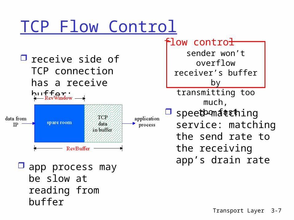
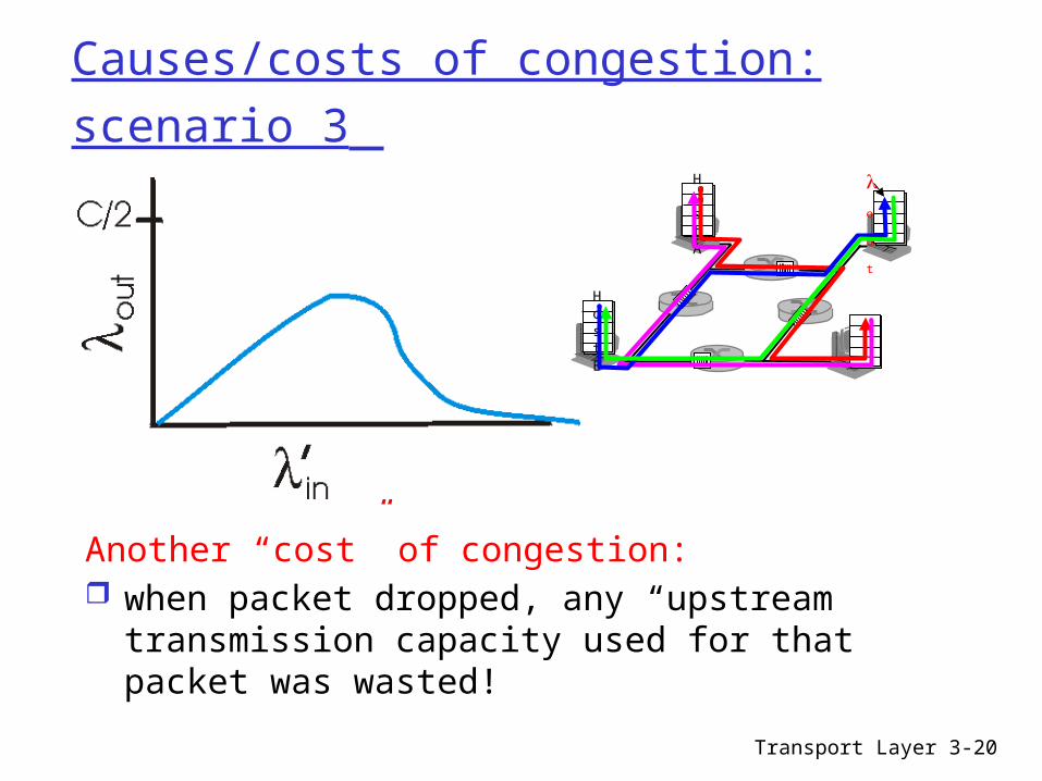
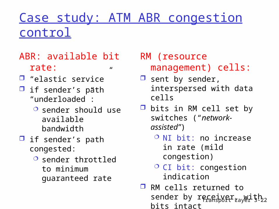
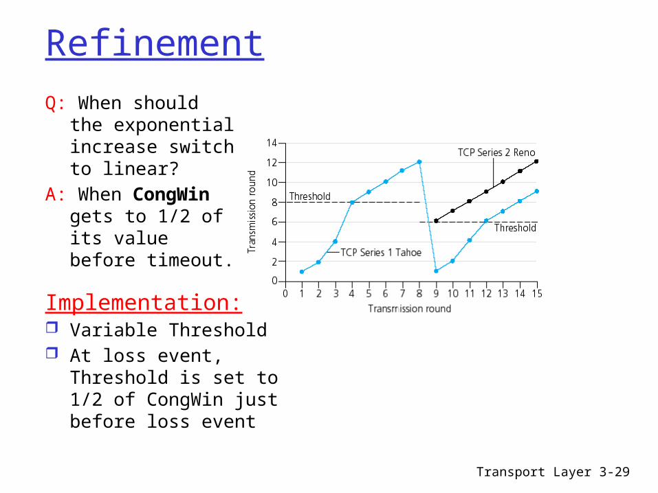


![National 5 iology Unit 2 – Multicellular Organisms1411]Unit_2_Multicellular_Organisms_Homework.pdf2 National 5 Unit 2: Multicellular Organisms Homework Booklet Is there anything](https://img.pdfslide.us/doc/110x75/5e84f223565dcc61b939eb2f/national-5-iology-unit-2-a-multicellular-organisms-1411unit2multicellularorganismshomeworkpdf.jpg)