Embed Size (px)
Citation preview
The Fundamentals of SONET
When fiber optical cables were initially deployed as a medium for high-speed digital transport, the lackof standards led to widespread deployment of proprietary optical interfaces. This meant that fiber optictransmission equipment from one manufacturer could not interface with equipment from any of theother manufacturers. Service providers were required to select a single vendor for deploymentthroughout the network and then were locked in to the network control and monitoring capabilities ofthat manufacturer. Although this technology satisfied the bandwidth needs of the network for severalyears, it was evident that this arrangement could not support the future needs of the industry becauseof the limited interconnection capabilities.
In 1985, Bellcore proposed the idea of an optical carrier-to-carrier interface that would allow theinterconnection of different manufacturers’ optical equipment. This was based on a hierarchy of digitalrates, all formed by the interleaving of a basic rate signal. The idea of a Synchronous Optical NETwork(SONET) attracted the interest of carriers, Regional Bell Operating Companies (RBOCs), andmanufacturers alike and quickly gained momentum. Interest in SONET by CCITT (now InternationalTelecommunication Union – ITU-T) expanded its scope from a domestic to an international standard,and by 1988 the ANSI committee had successfully integrated changes requested by the ITU-T, and werewell on their way toward the issuance of the new standard. Today, the SONET standard is contained inthe ANSI specification T1.105 Digital Hierarchy – Optical Interface Rates & Formats Specifications(SONET), and technical recommendations are found in Bellcore GR-253-CORE Synchronous OpticalNetwork (SONET) Transport Systems: Common Generic Criteria.
The SONET specifications define optical carrier (OC) interfaces and their electrical equivalents to allowtransmission of lower-rate signals at a common synchronous rate. One of the benefits of the SONETsignal, as with any standard, is that it allows multiple vendors to provide compatible transmissionequipment in the same span. SONET also allows for dynamic drop and insert capabilities on thepayload without the delay and additional hardware associated with demultiplexing and remultiplexingthe higher rate signal. Since the overhead is relatively independent of the payload, SONET is able tointegrate new services, such as Asynchronous Transfer Mode (ATM) and Fiber Distributed DataInterface (FDDI), in addition to existing DS3 and DS1 services. Another major advantage of SONET isthat the operations, administration, maintenance, and provisioning (OAM&P) capabilities are builtdirectly into the signal overhead to allow maintenance of the network from one central location.
SONET Multiplexing
SONET multiplexing combines low-speed digital signals such as DS1, DS1C, E1, DS2, and DS3 withrequired overhead to form a building block called Synchronous Transport Signal Level One (STS-1).Figure 1 shows the STS-1 frame, which is organized as 9 rows by 90 columns of bytes. It is transmittedrow first, with the most significant bit (MSB) of each byte transmitted first.
WEBSITE: www.jdsu.com
Technical Note
Overview

A generic formula calculates the bit rate of a framed digital signal:
bit rate = frame rate x frame capacity
In order for SONET to easily integrate existing digital services into its hierarchy, it was defined tooperate at the basic rate of 8 kHz or 125 microseconds per frame, so the frame rate is 8,000 frames persecond.
The frame capacity of a signal is the number of bits contained within a single frame. Figure 1 shows:
frame capacity = 90 bytes/row x 9 rows/frame x 8 bits/byte = 6,480 bits/frame
Now the bit rate of the STS-1 signal is calculated as follows:
bit rate = 8,000 frames/second x 6,480 bits/frame = 51.840 Mbps
Higher-rate signals are formed by combining multiples of the STS-1 block by interleaving a byte fromeach STS-1 to form an STS-3, as shown in Figure 2. The basic frame rate remains 8,000 frames persecond, but the capacity is tripled to result in a bit rate of 155.52 Mbps. The STS-3 may then beconverted to an optical signal (OC-3) for transport, or further multiplexed with three additional STS-3s to form an STS-12 signal, and so on. Table 1 defines common SONET optical rates, their equivalentelectrical rates, and the maximum number of DS0 voice channels which can be carried at that rate.
2Technical Note: The Fundamentals of SONET
Figure 1 STS-1 frame
9Rows
90 Bytes
B B B 87B
TransportOverhead
STS-1 Envelope Capacity
125 µs
B denotes an 8-bit byte
STS-1
STS-1
STS-1
3:1C B A C B A
STS-3
Figure 2 Multiplexing STS-1s
3Technical Note: The Fundamentals of SONET
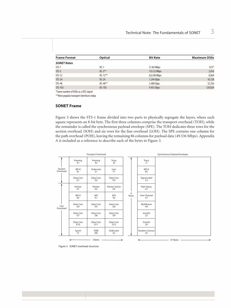
Frame Format Optical Bit Rate Maximum DS0s
SONET Rates
STS-1 OC-1 51.84 Mbps 672*
STS-3 OC-3** 155.52 Mbps 2,016
STS-12 OC-12** 622.08 Mbps 8,064
STS-24 OC-24 1.244 Gbps 16,128
STS-48 OC-48** 2.488 Gbps 32,256
STS-192 OC-192 9.953 Gbps 129,024
*Same number of DS0s as a DS3 signal
**Most popular transport interfaces today
SONET Frame
Figure 3 shows the STS-1 frame divided into two parts to physically segregate the layers, where eachsquare represents an 8-bit byte. The first three columns comprise the transport overhead (TOH), whilethe remainder is called the synchronous payload envelope (SPE). The TOH dedicates three rows for thesection overhead (SOH) and six rows for the line overhead (LOH). The SPE contains one column forthe path overhead (POH), leaving the remaining 86 columns for payload data (49.536 Mbps). AppendixA is included as a reference to describe each of the bytes in Figure 3.
Transport Overhead Synchronous Payload Envelope
SectionOverhead
LineOverhead
FramingA1
FramingA2
TraceJ0
BIP-8B1
OrderwireE1
UserF1
Data ComD1
Data ComD2
Data ComD3
PointerH1
PointerH2
Pointer ActionH3
BIP-8B2
APSK1
APSK2
Data ComD4
Data ComD5
Data ComD6
Data ComD7
Data ComD8
Data ComD9
Data ComD10
Data ComD11
Data ComD12
SynchS1
FEBEM0
OrderwireE2
TraceJ1
BIP-8B3
Signal LabelC2
Path StatusG1
User ChannelF2
MultiframeH4
GrowthZ3
GrowthZ4
Tandem ConnectZ5
3 Bytes 87 Bytes
9Rows
Figure 3 SONET overhead structure

SONET Signal Hierarchy
The SONET signal is layered to divide responsibility for transporting the payload through the network.Each network element (NE) is responsible for interpreting and generating its overhead layer, and forcommunicating control and status information to the same layer in other equipment – in short,“terminating” its overhead layer. As the payload travels through the SONET network, each layer isterminated by one of a general class of NEs, termed section terminating equipment (STE), lineterminating equipment (LTE), or path terminating equipment (PTE). Figure 4 illustrates a samplenetwork with the layered functions identified. The POH is generated at the point where the lower-ratesignal enters the SONET network by PTE such as a terminal multiplexer (TM). The POH is removedwhen the payload exits the network. Since the POH is first-on last-off, alarm and error informationcontained within this layer represents end-to-end status.
The next layer of overhead termination is the LOH and is performed by the LTE such as a SONETadd/drop multiplexer (ADM). The LOH is where most of the communication and synchronizationbetween NEs occurs, and represents error information between major nodes in the network. Finally,SOH is terminated by STE, such as optical regenerators, and contains error information between everynode in the network. In many cases, LTE, PTE, and STE functions are combined within the identicalpiece of equipment. Since each layer is terminated and regenerated at the appropriate nodes, theperformance monitoring data at each NE will help to sectionalize a problem.
For example, if traffic is traveling west to east in Figure 4, and section errors are detected at Site 4, aproblem will be somewhere between Site 3 and Site 4. The observed problem cannot be west of Site 3,since all section results are recalculated at every point in the network. If line errors are found at Site 4,a problem exists between Site 2 and Site 4, since line results are recalculated only at major nodes in thenetwork, such as the ADM at Site 2. Finally, if path errors are detected at Site 4, then a problem existsanywhere between Site 1 and Site 4.
The ADM at Site 2 adds a twist to the path errors example, due to its flexible functionality as shown inFigure 5. An ADM functions as a PTE when the signals being dropped and added are tributaries of theSONET signal. If the ADM has been equipped to add and drop DS3 or DS1 signals, the ADM functionsas a PTE for those signals. If it is equipped to add and drop STS-1 or OC-n signals, the ADM functionsonly as an LTE for those signals. This fact must be considered in the scenario in Figure 4. The pathstatement must be modified to add the condition that if path errors are located at Site 4, and the originof a DSn tributary within the STS-1 is at Site 1, then a problem exists between Site 1 and Site 4.Otherwise, if any Dsn tributary within the STS-1 originates from Site 2, then a problem exists betweenSite 2 and Site 4. So, in troubleshooting a signal, it is important to know where the path originates.
4Technical Note: The Fundamentals of SONET
Figure 4 Typical layered communication network
DSn DSn
West
CPE
East
CPE
TM ADM TMREGEN REGEN
OC-N OC-N OC-N OC-N
Path Layer
Line Layer Line Layer
Section Layer Section Layer Section Layer Section Layer
1 2 4
3
= Terminal Multiplexer= Customer Premises Equipment= Optical Regenerator= Add/Drop Multiplexer
TMCPE
REGENADM

5Technical Note: The Fundamentals of SONET
Since the origin of the signal is an important factor used to isolate trouble spots, the SONET signal itselfprovides a method to tag every STS-1 with information about its location. The J1 Path Trace Byte inAppendix A fills this role. This byte repetitively carries a fixed-length, 64-byte, ASCII string that can beprogrammed at system turn-up to carry textual information about the originating node, office, orcustomer. Because this information is never terminated by LTE or STE, it can only be assigned at theoriginating point of the signal.
SONET Performance Monitoring
Each layer in the SONET signal provides alarm and error monitoring capabilities between variousterminating points in the network. Similar to DS3 and DS1 signals, parity is calculated and stored inthe transmitted signal. The parity is recalculated by the receiver and verified against the stored value todetermine if an error occurred during transmission. Every layer in the SONET signal has its own BitInterleaved Parity (BIP) calculation. The sidebar on the next page shows how BIP checks are performedin SONET.
When an error is detected in a C-bit DS3 signal, a remote error indication (REI), formerly referred toas far-end block error (FEBE), is returned to the sender. SONET uses the same algorithm, using alayered approach. If an LTE receives some number of line BIP errors, it transmits the same number ofREI-L errors back to the originator. PTE use the same approach in the path layer of overhead. TheSONET signal also contains AIS and Yellow alarms, like DS3 and DS1, except a SONET Yellow alarm iscalled a remote defect indication (RDI), and is also layered like all of the other SONET results. The termRDI replaces the former names FERF (far-end receive failure) and RAI (remote alarm indication) fromprevious versions of the SONET specification.
Figure 5 Function of a SONET add/drop multiplexer
TerminalMultiplexer
TerminalMultiplexer
STS-1, OC-N
STS-1 STS-1
DSn DSn
OC-N OC-N
Signal is section, line, and path terminated
(ADM is PTE)
Signals are section and lineterminated (ADM is TE)

SONET Timing Compensation
The SONET signal was designed to be timing tolerant to support asynchronously timed, lower-ratesignals and slight timing differences between synchronously timed NEs. There are two mechanismswhich allow for robust timing compensation: variable bit stuffing of the lower-rate signal, and atechnique called “pointer adjustments” between synchronous elements in the SONET network.
Pointer Adjustments
Pointer adjustments allow the SPE to “float” with respect to the SONET frame. This means that a singleSPE payload frame typically crosses the STS-1 frame boundary, as shown in Figure 6. The “pointer” iscontained in the H1 and H2 bytes of the LOH and is a count of the number of bytes the J1 byte is awayfrom the H3 byte, not including the TOH bytes. A valid pointer can range from 0 to 782.
When timing differences exist, dummy bytes can be inserted into the SPE without affecting the data.Since the pointer is adjusted to indicate where the real POH starts, the receiving end can effectivelyrecover the payload (i.e., ignore the dummy bytes). When “stuffed bytes” are used, they are always inthe same location, regardless of where the POH starts. H3 is called a “negative stuff byte” and is used tocarry real payload data for one frame during a pointer decrement. The byte following H3 in the SPE iscalled a “positive stuff byte” and is used to carry a dummy byte of information for one frame during apointer increment.
6Technical Note: The Fundamentals of SONET
Bit Interleaved Parity (BIP)
BIP calculations are performed over each layer of the SONET overhead, such that each bit in theBIP byte will indicate the parity of all respective bits in the previous frame. For example, if thenumber of bits equaling one in the first bit position of every byte is odd, then the first bitposition of the BIP byte will be one. If the number of ones in the first position is even, then thefirst bit position of the BIP byte will be zero. This is repeated for all eight bits of each byte todetermine the value of the BIP byte.
Bytes in Transmitted Signal = 0110 0100
1010 1110
BIP Calculation = 1100 1010
Each layer calculates the BIP for all information in its domain. For example, since the entireSONET signal is formed when the STE sees it, the section BIP is calculated over the entire signal,including all SOH, LOH, and POH of the previous STS-n frame. The result is then placed in theB1 byte for STS-1 Number 1 of an STS-n. Line BIPs are calculated over the previous STS-1 frame,minus the SOH, and placed in the B2 byte for every STS-1 of an STS-n. Path BIPs are calculatedover the previous frame, minus SOH and LOH, and are found in the B3 byte of every STS-1 ofan STS-n.

7Technical Note: The Fundamentals of SONET
If there is no timing difference between two nodes, the incoming STS-1 payload bit rate is identical tothe transmit timing source that drives the outgoing STS-1 frame rate, so no pointer adjustments areneeded. Figure 7 shows a SONET node which has an incoming frequency f1 and an outgoing frequencyf2. If f1 is less than f2, there is a constant lack of payload data to place into the outgoing SONET signal.To compensate, a dummy byte is placed into the positive stuff byte and all the data is moved right byone byte, so the pointer is incremented by one (Figure 8). On the other hand, if f1 is greater than f2 asshown in Figure 9, then an extra SPE payload byte is stored into the negative stuff byte, H3, in the LOHfor one frame, while all the payload data is moved left by one byte and the pointer is decremented byone (Figure 10).
Figure 6 Pointer bytes designating the start of the SPE path overhead
STS-1 SPE
Frame N
Frame N + 1
125 µs
250 µs
9Rows
9Rows
3 Bytes 87 Bytes
H1 H2 H3
H1 H2 H3
J1
STS-1POH
SONET Node (LTE)
f1f2
f1< f2
Figure 7 Node with slower incoming data rate

8Technical Note: The Fundamentals of SONET
Figure 8 Incrementing the pointer value
Start of STS-1 SPE
Positive Stuff Byte(Dummy Byte)
H1 H2 H3
H1 H2 H3
H1 H2 H3
P
Pointer Value (P)
PNEW = P + 1
STS-1 Frame
0 µs
125 µs
250 µs
375 µs
Frame N + 2
Frame N + 1
Frame N
SONET Node (LTE)
f1f2
f1> f2
Figure 9 Node with faster incoming data rate

9Technical Note: The Fundamentals of SONET
An LTE is the only equipment which can perform path pointer adjustments, since the pointer value iscontained in the LOH. Also, path pointer adjustments are not performed by PTE, where the payloaddata enters the SONET network, even though there are potential timing differences at these locationsas well. The timing differences at PTE are due to asynchronously-timed tributary signals and arecorrected using traditional bit stuffing techniques.
Figure 11 shows a simplified version of how a SONET signal is assembled and disassembled tosummarize the layered responsibilities in SONET. All of the steps occur in a single 125 microsecondperiod over a single SONET frame.
Figure 10 Decrementing the pointer value
STS-1 Frame
125 µs
250 µs
375 µs
0 µs
Frame N
Frame N + 1
Frame N + 2
Negative Stuff Byte (Data)H1 H2
H1 H2 H3
H1 H2 H3
P
Pointer Value (P)
Start of STS-1 SPE
PNEW = P-1

10Technical Note: The Fundamentals of SONET
1
2
3
4
8
7
6
5
5
6
7
8
4
3
2
1
Append the path overhead to the tributary signal, using the previously calculated path BIP in the B3 byte.
Calculate the new path BIP value over the SPE and store for use in the next frame.
Assign a path pointer to the newly formed SPE in the line overhead (LOH).
Fill in the rest of the LOH using the previously calculated line BIP in B2.
Calculate the new line BIP value over the LOH and SPE and store for use in the next frame.
Insert all section overhead (SOH) except A1, A2, C1. Use the previous value of section BIP for the B1 location.
Scramble all of the data by Exclusive-Oring with the2^7-1 PRBS.
Insert the A1, A2, C1 bytes into the SOH. Calculate thesection BIP over the entireSTS-1, saving for use in the next frame.
Detect the frame word bytes to find the start of the STS-1 frame.
Calculate the section BIP over the entire STS-1 and save for use in the next frame.
Descramble all of the data by Exclusive-Oring with the 2^7-1 PRBS. Compare B1 byte to previously saved value and report section BIP errors if discrepancies are found.
Examine the pointer value to find the start of the SPE.Handle pointer adjustments.
Examine B2 byte and compare it to last saved version of the line BIPs. Report line BIP errors if any found.
Calculate a BIP over the line overhead and the SPE. Save it for use in the next frame.
Examine B3 byte and compare it to last saved version of path BIPs. Report path BIP errors if discrepancies are found.
Calculate the path BIP over the SPE and store for use in next frame. Separate the path overhead from the payload so it can be dropped as needed.
Transmit Functions Receive Functions
Path Layer
Line Layer
Section Layer
REI-P
REI-L
Figure 11 Assembling and disassembling the SONET signal
11Technical Note: The Fundamentals of SONET
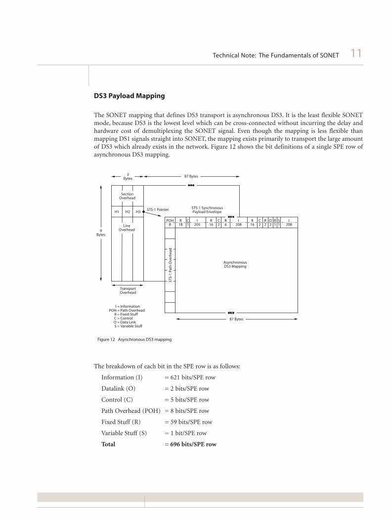
DS3 Payload Mapping
The SONET mapping that defines DS3 transport is asynchronous DS3. It is the least flexible SONETmode, because DS3 is the lowest level which can be cross-connected without incurring the delay andhardware cost of demultiplexing the SONET signal. Even though the mapping is less flexible thanmapping DS1 signals straight into SONET, the mapping exists primarily to transport the large amountof DS3 which already exists in the network. Figure 12 shows the bit definitions of a single SPE row ofasynchronous DS3 mapping.
The breakdown of each bit in the SPE row is as follows:
Information (I) = 621 bits/SPE row
Datalink (O) = 2 bits/SPE row
Control (C) = 5 bits/SPE row
Path Overhead (POH) = 8 bits/SPE row
Fixed Stuff (R) = 59 bits/SPE row
Variable Stuff (S) = 1 bit/SPE row
Total = 696 bits/SPE row
Figure 12 Asynchronous DS3 mapping
3Bytes
87 Bytes
9Bytes
SectionOverhead
H1 H2 H3
LineOverhead
TransportOverhead
STS-1 Pointer STS-1 SynchronousPayload Envelope
POH8
R18
R16
R16
R6
C1
C2
C2
R2
R1
S1
O2
I205
I208
I208
AsynchronousDS3 Mapping
87 Bytes
STS-
1 Pa
th O
verh
ead
= Information= Path Overhead= Fixed Stuff= Control= Data Link= Variable Stuff
IPOH
RCOS

Currently, the datalink bits are undefined. Each row has the opportunity to use the variable stuff bit tocarry payload data, which is indicated by setting each of the five control bits to 1. Majority vote on thecontrol bits is used at the receiving end to detect if the variable stuff bit contains real or dummyinformation, so that dummy bits can be removed from the signal before the DS3 is passed to otherasynchronous equipment, such as M13 multiplexers.
Using all of the variable stuff bits for data, it is possible to calculate the maximum DS3 rate which canbe transmitted with this mapping.
(1 variable bit/row + 621 data bits/row) x 9 rows/frame x 8,000 frames/second = 44.784 Mbps
Calculating the minimum DS3 rate which can be carried with this mapping is accomplished bycalculating the payload using none of the variable stuff bits.
621 data bits/row x 9 rows/frame x 8,000 frames/second = 44.712 Mbps
Since the nominal DS3 frequency is 44.736 Mbps, the average stuffing rate for this mapping can bedetermined.
44.736 Mbps - 44.712 Mbps = 24 kbps of variable stuffing
The average stuff rate for a DS3 implies that three of the nine variable stuff bits are used in each frameto carry data. As a side note, the total amount of overhead that is included with the SPE to transmit theDS3 is calculated as follows:
(59 fixed stuff bits/row + 2 datalink bits/row + 5 control bits/row + 8 POH bits/row +
1 variable stuff bit/row) x 9 rows/frame x 8,000 frames/second = 5.4 Mbps
Virtual Tributaries
To transport payloads requiring less capacity than a DS3 signal, the 783-byte SPE is divided into sevenvirtual tributary (VT) groups of 12 columns each. The seven groups are combined with the POH andtwo fixed stuff columns to fill the entire STS-1 SPE.
VT Groups = 7 groups x 12 columns/ groups x 9 bytes/column = 756 bytes
Fixed Stuff = 2 columns x 9 bytes/column = 18 bytes
Path Overhead = 1 column x 9 bytes/column = 9 bytes
Total = 783 bytes
VT groups are analogous to DS2 framed signals. In other words, smaller tributaries can be multiplexedand placed within a VT group. Individual VTs come in different sizes, termed VT1.5, VT2, VT3, andVT6, to convey the approximate bandwidth which can be carried by the tributary, as shown in Figure13. A VT1.5, for example, consumes three columns per STS-1 frame to accommodate the following bitrate:
3 columns/frame x 9 bytes/column x 8 bits/byte x 8,000 frames/second = 1.728 Mbps
The VT1.5 is used to transport a DS1 at 1.544 Mbps plus required overhead. A VT2 uses four columnsper STS-1 frame, so its carrying capacity is:
4 columns/frame x 9 bytes/column x 8 bits/byte x 8,000 frames/second = 2.304 Mbps
12Technical Note: The Fundamentals of SONET

13Technical Note: The Fundamentals of SONET
Since there are 12 columns in a VT group, four individual VT1.5s may fit into a single VT group.Likewise, only three VT2s, two VT3s, or one VT6 can fit in a group, as shown in Figure 14. Althoughdifferent VT groups within a single STS-1 SPE can carry different sized VTs, different sized VTs cannotbe combined within a single VT group. Figure 15 illustrates the STS-1 SPE configured to carry VT1.5sin all seven VT groups, for a total of 28 VT1.5s.
Figure 13 Available virtual tributaries
108
27Bytes
VT1.5
1
2
3
27125 µs 125 µs
125 µs
1
2
3
4
36125 µs
9Rows
54Bytes
4
1 2 3
3 Columns
27
1
VT3
54 54
1
7
2 3 4 5 6
6 Columns
9Rows
12 Columns
1
13
2 3 4 5 6 7 8 9 10 11 12
108Bytes
9Rows
9Rows
36Bytes
108
4
3
2
1
VT6
4 Columns
1
5
2 3 4
36
VT2
Figure 14 VT group capacity
4 VT 1.5
3 VT 2
2 VT 3
1 VT 6
12 12 12 12
9

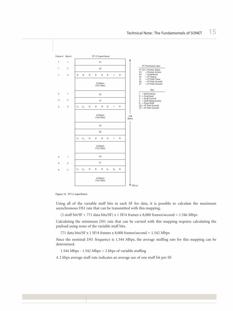
VT1.5 Structure
For further study of VT structure, the asynchronous VT1.5 mapping will be used an an example. TheVT1.5 SPE is similar to the STS-1 SPE, since it contains dedicated performance monitoring overhead,and a pointer is used to detect its start. However, structural differences make the VT SPE unique. AVT1.5 SPE is divided over four consecutive STS-1 frames to form a superframe (SF) as shown in Figure16. The VT overhead is directly analogous to the POH, since it travels with the DS1 from entry to exitand contains additional end-to-end performance monitoring specific to the DS1. There are 771 bits inthe VT SF for data and two stuffing bits to compensate for timing differences caused by theasynchronous DS1 payload. The breakdown of each bit in the VT1.5 SF is as follows:
Information (I) = 771 bits/SF
Stuff Opportunities (S) = 2 bits/SF
Stuff Control (C) = 6 bits/SF
Overhead (O) = 8 bits/SF
Fixed Stuff (R) = 13 bits/SF
VT Overhead = 40 bits/SF
Total = 840 bits/SF
14Technical Note: The Fundamentals of SONET
Figure 15 STS-1 frame configured to carry 28 VT1.5 payloads
1 29 30 31 32 33 58 59 60 61 62 87
1 J1
B3
C2
G1
F2
H4
Z3
Z4
Z5
R
R
R
R
R
R
R
R
R
2
3
4
5 1 2 3 28 21 3
R
R
R
R
R
R
R
R
R
28 2821 3
6
7
8
9
STS-1Path Overhead
Bytes
Fixed StuffBytes
Fixed StuffBytes
15Technical Note: The Fundamentals of SONET
Using all of the variable stuff bits in each SF for data, it is possible to calculate the maximumasynchronous DS1 rate that can be transmitted with this mapping.
(2 stuff bit/SF + 771 data bits/SF) x 1 SF/4 frames x 8,000 frames/second = 1.546 Mbps
Calculating the minimum DS1 rate that can be carried with this mapping requires calculating thepayload using none of the variable stuff bits.
771 data bits/SF x 1 SF/4 frames x 8,000 frames/second = 1.542 Mbps
Since the nominal DS1 frequency is 1.544 Mbps, the average stuffing rate for this mapping can bedetermined.
1.544 Mbps - 1.542 Mbps = 2 kbps of variable stuffing
A 2 kbps average stuff rate indicates an average use of one stuff bit per SF.
Figure 16 VT1.5 superframe
V4
Z7
C1 C2 R R R S1 S2 R
24 Bytes(192 I Bits)
24 Bytes(192 I Bits)
2
2
2
1
2
3
4
4
4
1
2
3
Frame # Byte # VT1.5 Superframe
1
1
1
1 V1
V5
V2
J2
V3
Z6
2
3 R R R R R R I R
C1 C2 O O O O I R
C1 C2 O O O O I R
24 Bytes(192 I Bits)
24 Bytes(192 I Bits)
500 µs
108Bytes
VT Overhead Layer
= Pointer Value= Pointer Action= Undefined= VT Status= VT Path Trace= VT Path Growth= VT Path Growth
V1-V2V3V4V5J2Z6Z7
Bits
= Information= Overhead= Stuff Control= Stuff Opportunity= Fixed Stuff= VT Path Growth= VT Path Growth
IOCSRZ6Z7

VT1.5 Mapping Modes
There are two conventional modes to map Vts into the SONET signal: locked and floating. The lockedmode uses fixed locations within the SPE for the VT data,allowing easy access to the 64 kbps voicechannel directly within the SONET signal. Although the STS-1 SPE is still allowed to float with respectto the STS-1 frame in all mappings, the locked VT payload is not allowed to float with respect to theVT overhead. This restriction prevents the VT cross-connects from adjusting the VT in the samemanner that is allowed at the SPE level. For this reason, the locked mode has been dropped altogetherfrom the ANSI T1.105 specification. Figure 17 illustrates the locked mapping.
The prevailing multiplexing technique (floating mode) allows the lower-rate signal to retain minimumtiming consistency with the SONET network clock. This mapping permits the DS1 to float relative tothe VT overhead. Unlike locked mode, a floating VT uses a VT pointer to show the starting byte positionof the VT SPE within the VT payload structure. In this sense, the operation of the VT pointer is directlyanalogous to the path pointer, and has the same advantages of minimizing payload buffers andassociated delay when cross-connecting at the VT level. Figure 18 shows conceptually how the path andVT pointers are used to locate a particular VT payload in a SONET frame. The solid VT box combinesthe V1-V3 bytes from the SF to represent the pointer. This pointer is incremented and decremented atVT cross-connects in exactly the same manner as the path pointer, to compensate for timing differencesbetween two SONET signals.
16Technical Note: The Fundamentals of SONET
Figure 17 Locked VT mapping
VT
TransportOverhead
9Bytes
LineOverhead
SectionOverhead
3Bytes 87 Bytes
VT VT
Locked-ModeDS1 Mapping
Locked-ModeDS1 Mapping
Locked-ModeDS1 Mapping
VT1.5
STS-
1 Pa
th O
verh
ead
STS-1 SynchronousPayload Envelope

17Technical Note: The Fundamentals of SONET
Floating mappings are further classified as channelized or unchannelized as an indication of the lowestlevel of cross-connecting that can be accomplished with the mapping. The channelized (byte-synchronous) mapping, as shown in Figure 19, is observable at the DS0 level and is consequently verypopular in integrated digital loop carrier (IDLC) applications. Since the DS0s can be removed andinserted directly into the SONET signal without the typical cost and delay of an additional 1/0 cross-connect, cost savings can be realized in the deployment of DS0 grooming architectures. This capabilitytechnically would allow equipment to route calls through the local loop without having the call travelthrough the main switch in the central office. When the billing software is able to support thisapplication, this technology will become more widespread. Additionally, the extension of SONET intothe local loop brings with it added protection and OAM&P messaging. The disadvantage of thismapping is that it requires additional slip buffers to byte align the DS1 signal within the mapping, so itmay be slightly more expensive to implement than unchannelized systems.
Figure 18 Using the VT pointer
3Bytes
SectionOverhead
STS-1 PointerH1 H2 H3
LineOverhead9
Bytes
TransportOverhead
STS-
1 Pa
th O
verh
ead
VT Pointer
VT
VT Floating Mode
125 µs
1
2
3
87 Bytes
STS-1 SynchronousPayload Envelope

Unchannelized (asynchronous and bit-synchronous) mappings are only observable at the VT level.Asynchronous and bit-synchronous mappings are identical in physical appearance, as shown in Figure20. The difference between these mappings is in the flexibility of the tributary stuffing as the DS1 entersthe SONET network, as described in VT1.5 Structure. Bit-synchronous systems are forced to use onevariable stuff bit per SF, while asynchronous mappings are allowed to compensate for differencesbetween the DS1 and the SONET clock. As a result, systems incorporating the bit-synchronousmapping require the incoming DS1 to be timed directly to the SONET network clock. There are no slipbuffers required to implement these mappings, so equipment may be less expensive, making it popularin long distance applications. For access to the DS0 channels, a 1/0 cross-connect is required for bothof these mappings, however transport systems are generally concerned with cross-connecting at higherrates than voice. The efficiency and flexibility of the asynchronous mapping makes it the mostcommon.
Protection Switching
With upwards of 32 thousand telephone calls over a single OC-48, disaster recovery is substantiallymore important to service providers today than it has been in the past. Therefore, a major requirementof any future widely deployed transmission standard is the ability to withstand catastrophic failureswithout severely affecting service. The SONET network is able to weather these failures due todeployment of SONET ring architectures and automatic protection switching (APS) algorithms. Thesemechanisms allow live traffic to flow through a new path whenever the old path is disrupted or becomesdegraded.
18Technical Note: The Fundamentals of SONET
Figure 19 Byte synchronous floating mode
3Bytes
9Bytes
SectionOverhead
LineOverhead
TransportOverhead
87 Bytes
VTVT
Byt
e-Sy
nch
ron
ou
sD
S1 M
app
ing
STS-
1 Pa
th O
verh
ead
Byt
e-Sy
nch
ron
ou
sD
S1 M
app
ing
STS-1 SynchronousPayload Envelope
VT1.5
VT1.5
VT
Byt
e-Sy
nch
ron
ou
sD
S1 M
app
ing

19Technical Note: The Fundamentals of SONET
Linear Systems
A linear (point-to-point) network can be implemented with working and protect (or primary andsecondary) fibers deployed in different locations (route diversity). Also called 1+1, both the workingand protect lines carry identical traffic, permitting the receiving end to monitor the status of each linein real time. If the working line becomes degraded or is disrupted, the receiver simply switches to theprotect fiber. The degraded threshold is programmable and is usually set at a line BIP error rate of 1E-7 or 8. This type of switching is also called “tail-switched,” since switching decisions take place at thetail (receiving) end of a signal. Unfortunately the cost of fiber, receivers, and transmitters is doubledbetween every protected node, as compared to a non-protected system. The cost of this protection canbe reduced by using a 1:n architecture, where n is between 1 and 14. This architecture is similar to 1+1with two major differences. First, even in a 1:1 architecture, the protect line is not carrying the identicaltraffic so the transmitting end must request a switch. Second, since there is one protect line for nworking lines, there is a possibility that a working line will not be granted a switch. The head(transmitting) end determines the priority of the requestor and either honors or ignores the receiver’srequest to switch, hence this architecture is also called “head-switched.”
Figure 20 Asynchronous floating mode
3Bytes
SectionOverhead
LineOverhead
9Bytes
TransportOverhead
STS-
1 Pa
th O
verh
ead
VT VT VT
Asy
nch
ron
ou
s o
rB
it-S
ynch
ron
ou
sD
S1 M
app
ing
VT1.5
VT1.5
Asy
nch
ron
ou
s o
rB
it-S
ynch
ron
ou
sD
S1 M
app
ing
Asy
nch
ron
ou
s o
rB
it-S
ynch
ron
ou
sD
S1 M
app
ing
STS-1 SynchronousPayload Envelope
87 Bytes

Unidirectional Path Switched Rings
The simplest ring is the 2-fiber unidirectional path switched ring (UPSR) as shown in Figure 21. Theterm unidirectional is used to describe the direction of traffic under normal circumstances, or when thering is “clean”. In a UPSR, the traffic is only routed one direction (usually clockwise) unless troublesoccur. For example, traffic entering at point A and exiting at point B travels clockwise. Traffic enteringat point B and exiting at point A also travels clockwise.
Protection is accomplished by automatically bridging all traffic counterclockwise at entry nodes.Exactly one-half of the capacity of the ring is therefore reserved for protection. On an OC-48 ring,STS-1 channels 1 … 24 would be reserved for clockwise traffic, while channels 25 … 48 would bereserved for counterclockwise protection. Protection channels can also be configured on a VT basis. Thenode which handles the exit of the traffic simply selects the better of the two directions, much like 1+1protection of a point-to-point system. The UPSR does not utilize automatic protection switching (APS)messages for switching. The exit nodes examine individual path or VT overhead indicators toindependently select STS-1 or VT signals. Since no communication is required between the entry andexit nodes, the protection switch time is not affected by the number of nodes in the ring, as is the casewith the line switched rings.
Bidirectional Line Switched Rings
Unlike UPSR, a bidirectional line switched ring (BLSR) may be architected with either 2-fibers or the4-fiber ring as shown in Figure 22. A 2-fiber BLSR is similar to a UPSR, except that traffic is routed inboth directions around the ring under normal circumstances. For example, traffic entering at point Aand exiting at point B travels clockwise, while traffic entering at point B and exiting at point A travelscounterclockwise. This method allows the most efficient use of deployed equipment and fiberresources.
20Technical Note: The Fundamentals of SONET
Figure 21 Unidirectional path switched ring
DS3 and DS1
DS3 and DS1
A
Secondary
Primary
DS3andDS1
DS3andDS1
B

21Technical Note: The Fundamentals of SONET
In a BLSR, the STS-1 or VT traffic is not bridged in the opposite direction unless APS signaling betweenthe entry and the exit node specifically requests the channel be placed on protection. The APSmessaging may be accompanied by further instructions contained in the section DCC. Since the BLSRrequires communication, a switch time requirement of 50 milliseconds restricts the BLSR to 16 nodes.An advantage is that bidirectional traffic allows network planners to periodically reroute signals forpurposes of load-balancing.
A 4-fiber BLSR uses two types of protection switching: span switching and ring switching. Normaltraffic is routed exactly as the 2-fiber BLSR, however if the transmit and receive fiber pair bundle is cutor degraded between points A and B, a “span switch” occurs. The span switch routes traffic over theprotected fiber pair much like 1:1 protection on a point-to-point system, and no directional re-routingis required. If both fiber pairs are degraded or a node fails, then a “ring switch” occurs by routing trafficaway from the failure. Unlike the UPSR, a BLSR examines only LOH performance indications todetermine quality of service. The monitoring does not extend to the path or VT layer.
Span switching and ring switching can be used simultaneously in a 4-fiber BLSR to protect traffic in theevent of multiple failures on the same ring. If both of these switching methods are used, the ring switchwill require “extra traffic” to be dropped if the ring is full. One advantage of the 4-fiber BLSR is that thecapacity is doubled over the 2-fiber rings since protection channels are not reserved, however the costof fiber optic cables, transmitters, and receivers is doubled.
One additional parameter which is used to describe protection switching mechanisms indicates whathappens when the original line has returned to an acceptable performance level. “Revertive” systemswill restore working traffic on the original path and “non-revertive” systems will simply change thedefinition of “working” to describe the line which is currently being used.
Figure 22 Bidirectional line switched ring
DS3 and DS1
DS3 and DS1
A
Secondary
Primary
DS3andDS1
DS3andDS1
B

Broadband Services
The SONET specification provides a means to offer services that require a larger bandwidth than asingle STS-1 (broadband) by uniting the previously independent STS-1s to form a phase and frequencyaligned pipe. An example is OC-3c, so named because it is formed by concatenating three STS-1s andthen transmitting them optically. The payload pointer in the first STS-1 points to the beginning of theSPE as usual, but all three SPEs are aligned and referenced by this pointer to create a contiguous 149.760Mbps envelope. Figure 23 illustrates a concatenated OC-3c payload envelope. The pointers in thesecond and third STS-1 frames still physically exist along with a normal TOH, however they contain aspecial value which indicates to use the pointer value from STS-1 Number 1. The traditional POHcolumns in the SPE in the second and third STS-1 frames are replaced with data. Today, the demandfor concatenated pathways is very high to accommodate ATM growth.
OC-12c is another concatenated signal gaining in popularity, and provides 599.040 Mbps of capacity,since there is one POH column for each group of three STS-1 frames throughout the OC-12. An OC-12c can transport about 1.4 million ATM packets every second.
Summary
The SONET signal embeds performance monitoring, maintenance, provisioning, and operationsinformation directly within the signal format. It combines mechanisms to allow for timinginconsistencies throughout the network and provides a means for transporting a wide variety ofservices. It allows tributary drop and insert while reducing equipment cost and timing delay to provideon/off ramps to the industry analogy of the “superhighway.” Rings may be architected to provide a highdegree of service quality, even in the presence of multiple failure conditions. These advantages add upto provide a powerful network standard which will continue to grow in popularity into this next era oftelecommunications improvements.
22Technical Note: The Fundamentals of SONET
Figure 23 STS-3c mapping for broadband services
260
J1
B3
C2
G1
F2
H4
Z3
Z4
Z5
9Rows
STS-3c POH
53
h ATM Cell
h
hh

23Technical Note: The Fundamentals of SONET
Appendix A: SONET Section, Line, Path and VT Overhead Layers
Many of the bytes in the tables of this appendix are undergoing further definition and/or modificationat the time of this writing.
Byte Name Description
SONET Section
A1-A2 Framing Bytes Provides frame alignment of each STS-1 within an STS-n (n = 1, 3, 12…).The value is hexadecimal F628.
J0-Z0 Trace Growth (STS-1 ID) Redefined byte to provide section trace functionally and growth
B1* Section BIP-8 Provides section error monitoring using a bit-interleaved parity 8 code (BIP-8) using even parity. It is calculated
over all bytes of the previous STS-n frame.
E1* Section Orderwire Provides a 64 kbps voice channel for communication between two STEs
F1 User 1 Reserved for user purposes
D1-D3* Section DCC Provides a 192 kbps Data Communications Channel (DCC) between two STEs, to allow for message-based adminis-
tration, monitoring, and other communications needs
*Only defined for the first STS-1 of an STS-n
Byte Name Description
SONET Line
H1-H2 Pointer Provides a byte offset value to indicate where the path overhead begins with each SPE
H3 Pointer Action Provides an extra byte for a negative stuff opportunity needed to perform a pointer decrement without losing any
data. It is defined for all STS-1s within an STS-n.
B2 Line BIP-8 Provides line error monitoring, by calculating a bit-interleaved, even parity check over all bits of the line overhead
and SPE, excluding the SOH of the previous STS-1 frame
K1-K2* APS Bytes Provides APS signaling between two LTEs
D4-D12* Line DOC Provides a 576 kbps DCC between two LTEs for administration, monitoring, and other communications
S1/Z1 Sync Status/Growth Provides information about the quality of the timing source. Also allows for future growth.
M0 REI-L/Growth Provides error count detected by LTE back to peer LTE
E2* Line Orderwire Provides a 64 kbps voice channel for communication between LTEs
*Only defined for the first STS-1 of an STS-n
Byte Name Description
SONET Path
J1 Path Trace Provides an indication of path connectivity by repeating a 64-byte fixed-length ACSII text string which is inserted
when the payload is mapped. Installation crews can modify the string to indicate the tributary source
B3 Path BIP-8 Provides path error monitoring, by calculating a bit-interleaved, even parity check over all bits of the previous SPE,
excluding the LOH and SOH
C2 Signal Label Provides an identification byte for the inserted payload
00 STS path unequipped
01 Equipped – non-specific payload
02 Floating VT mode
03 VT locked mode
04 Asynchronous mapping for DS3
12 Asynchronous mapping for DS4NA
13 Mapping for ATM
14 Mapping for DQDB
15 Asynchronous mapping for FDDI
E1-FC STS-1 payload with VT payload defects
G1 Path Status Provides a method for communicating for far-end path status back to the path originating equipment
F2 Path User Channel F2 is a 64 kbps channel reserved for user communication between two PTEs
H4 Multiframe Indicator Provides a multiframe phase indication of a VT payload to identify phases of a SF
Z3-Z5 Growth/User Partially reserved for growth and network provider layer information

Byte Name Description
SONET VT
V5 VT Status Provides error checking, signal label, and path status
J2 VT Path Trace Provides support for VT path trace function
Z6 VT Path Growth Future growth
Z7 VT Path Growth Future growth
24Technical Note: The Fundamentals of SONET
All statements, technical information and recommendations related to the products herein are based upon informa-
tion believed to be reliable or accurate. However, the accuracy or completeness thereof is not guaranteed, and no
responsibility is assumed for any inaccuracies. The user assumes all risks and liability whatsoever in connection with
the use of a product or its application. JDSU reserves the right to change at any time without notice the design,
specifications, function, fit or form of its products described herein, including withdrawal at any time of a product
offered for sale herein. JDSU makes no representations that the products herein are free from any intellectual
property claims of others. Please contact JDSU for more information. JDSU and the JDSU logo are trademarks of
JDS Uniphase Corporation. Other trademarks are the property of their respective holders. ©2006 JDS Uniphase
Corporation. All rights reserved. 30137297 500 0106 FUNDSONET.TN.DAT.TM.AE