Embed Size (px)
Citation preview

! "#$%$&'()&(&$&%*
!"#$%"&#$&'$()*+,&#$&-.%*#.#&/.0.&-$,)0"(&#$&1#23.3*+,&4,*3*.%
!!!"#$%&'()$%*(+,-"*+!!!"$./*,*'()0*1"*+
Outline
Project objectives
Why do we need raw data?
Decoding the information
Format description
Modeling the instrument
Waveform processing
Study area & first results
Perspectives USGS
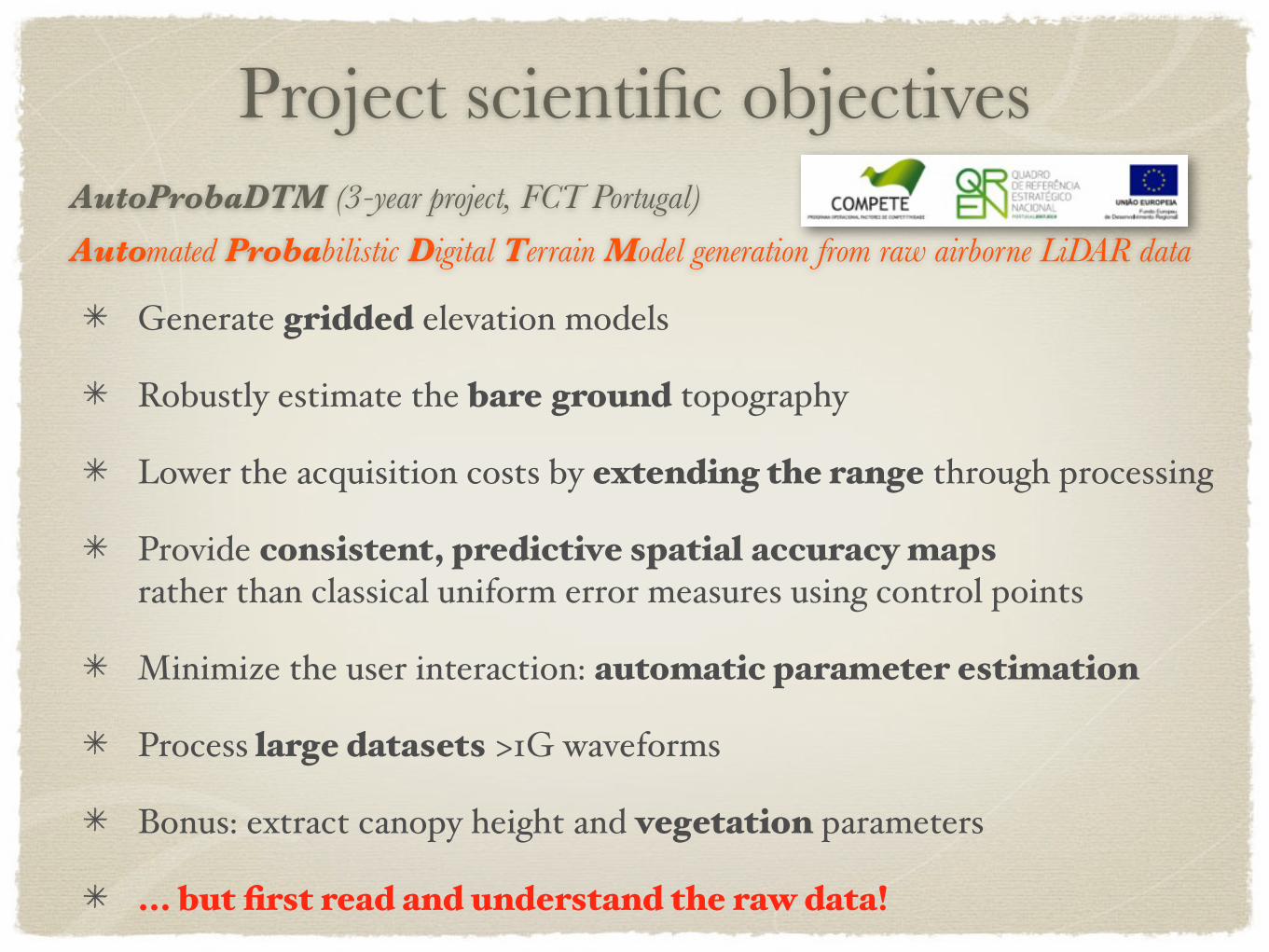
Project scientific objectives AutoProbaDTM (3-year project, FCT Portugal)
Automated Probabilistic Digital Terrain Model generation from raw airborne LiDAR data
Generate gridded elevation models
Robustly estimate the bare ground topography
Lower the acquisition costs by extending the range through processing
Provide consistent, predictive spatial accuracy mapsrather than classical uniform error measures using control points
Minimize the user interaction: automatic parameter estimation
Process large datasets >1G waveforms
Bonus: extract canopy height and vegetation parameters
... but first read and understand the raw data!
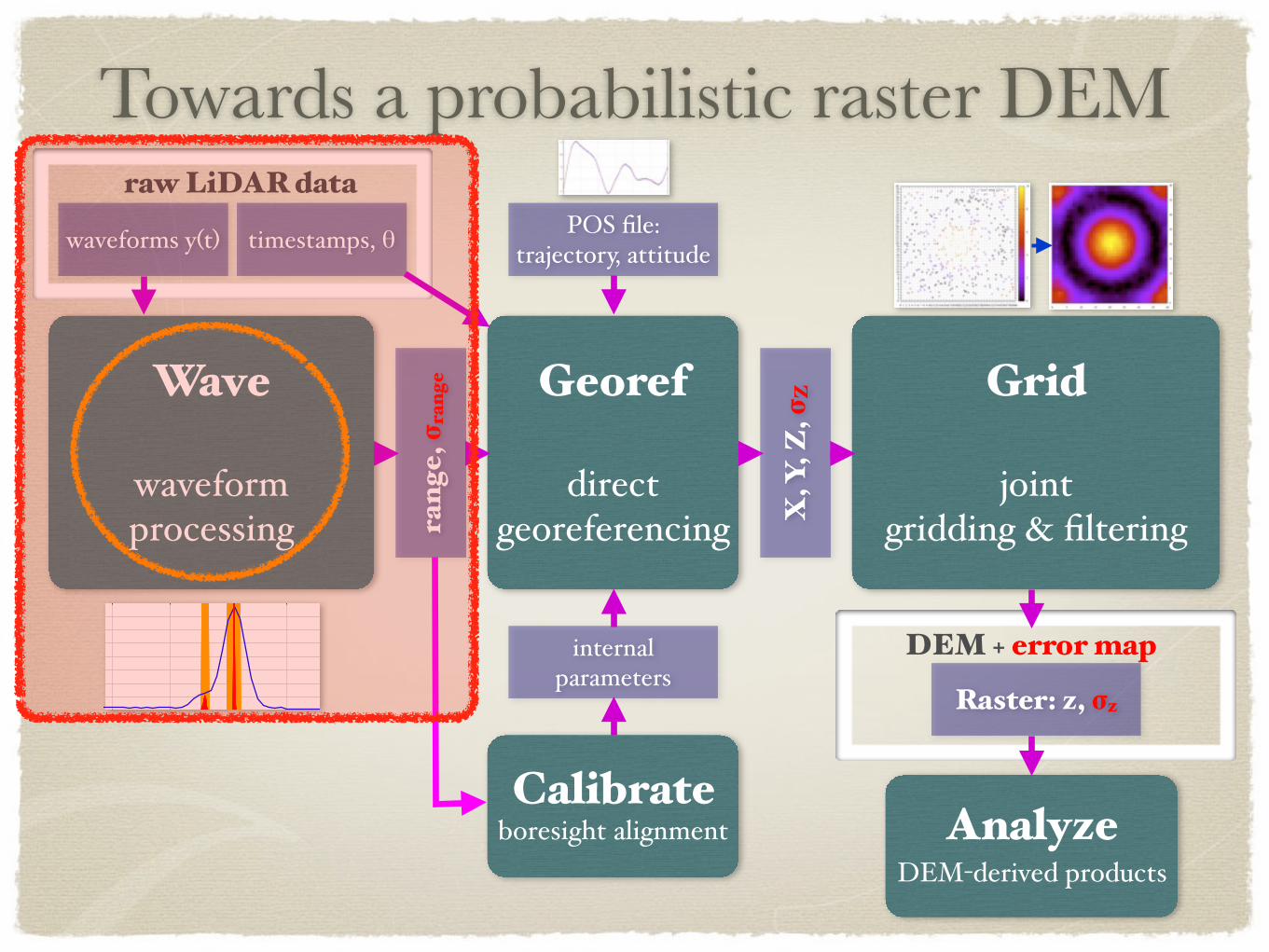
Towards a probabilistic raster DEM
Wave
waveformprocessing
Georef
directgeoreferencing
Grid
jointgridding & filteringra
nge,
σra
nge
X, Y
, Z, σ
Z
Raster: z, σz
POS file:trajectory, attitudewaveforms y(t) timestamps, θ
raw LiDAR data
DEM + error map
Calibrateboresight alignment Analyze
DEM-derived products
internalparameters
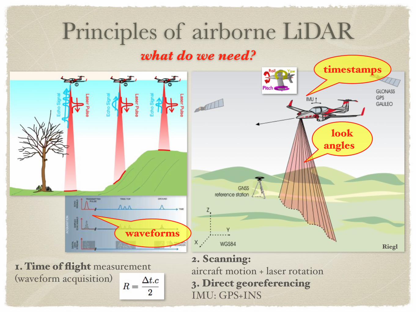
Principles of airborne LiDAR
1. Time of flight measurement(waveform acquisition)
2. Scanning:aircraft motion + laser rotation3. Direct georeferencingIMU: GPS+INS
Riegl
waveforms
look angles
timestampswhat do we need?
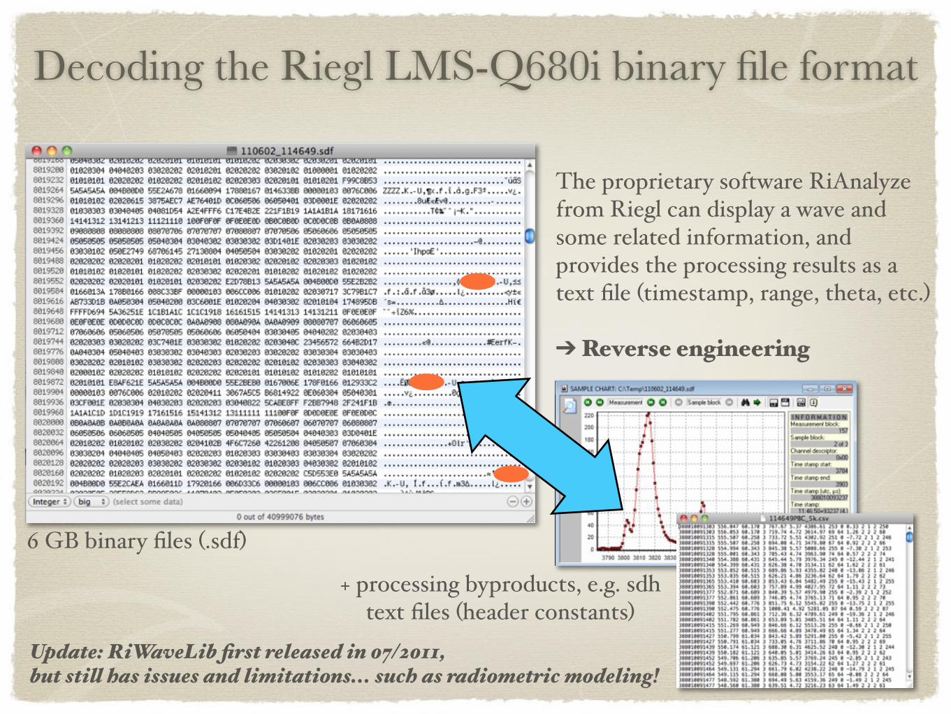
Decoding the Riegl LMS-Q680i binary file format
6 GB binary files (.sdf)
The proprietary software RiAnalyzefrom Riegl can display a wave and some related information, and provides the processing results as a text file (timestamp, range, theta, etc.)
➔ Reverse engineering
Update: RiWaveLib first released in 07/2011, but still has issues and limitations... such as radiometric modeling!
+ processing byproducts, e.g. sdh text files (header constants)
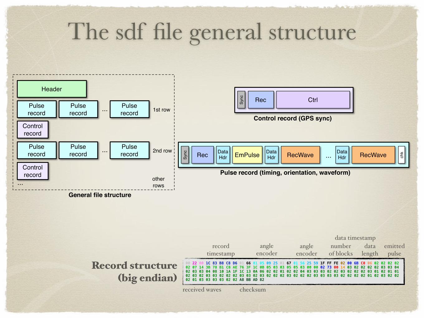
The sdf file general structure
Header
Pulserecord ...
Sync Rec Data
Hdr EmPulse RecWave RecWave... chk
Sync Rec Ctrl
Controlrecord
Pulserecord
Pulserecord
Pulserecord
Pulserecord
Pulserecord
1st row
2nd row
Controlrecord
...
...
Control record (GPS sync)
Pulse record (timing, orientation, waveform)otherrows
General file structure
DataHdr
DataHdr
00 22 00 1C 83 B8 C8 D6 01 66 01 05 09 25 01 67 01 56 25 59 1F FF FE 02 00 6B C0 06 02 02 02 02 02 07 14 3B 78 B1 C8 AE 76 3F 1C 0B 05 03 03 05 05 03 00 00 02 73 00 14 03 02 02 02 02 03 03 04 02 03 03 04 08 10 1A 1F 1C 13 0A 06 02 02 01 02 02 04 03 03 03 02 02 03 02 02 02 03 01 02 01 01 02 03 02 03 03 02 02 02 03 03 02 03 02 02 02 03 02 02 02 03 03 03 03 02 02 02 02 01 02 03 02 02 02 01 03 03 03 03 02 02 A8 BB AD 82
angleencoder
recordtimestamp
datalength
numberof blocks
data timestamp
received waves checksum
Record structure(big endian)
angleencoder
emittedpulse
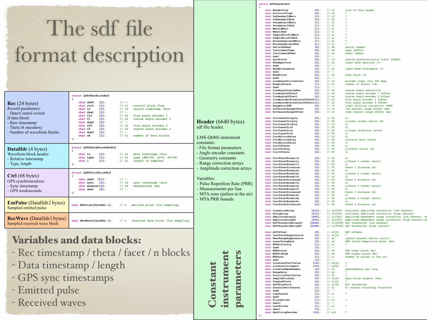
The sdf fileformat description
Rec (24 bytes)Record parameters:- Data/Control switchIf data block:- Raw timestamp- Theta (4 encoders)- Number of waveform blocks
struct Q680RecBlockBuf { char dum0 [2]; // -- char ctrl [1]; // u1 control block flag char tc [5]; // i5 record timestamp (4ns) char dum1 [2]; // -- char C1f [2]; // u2 fine angle encoder 1 char C1 [2]; // u2 coarse angle encoder 1 char dum2 [2]; // -- char C2f [2]; // u2 fine angle encoder 2 char C2 [2]; // u2 coarse angle encoder 2 char dum3 [3]; // -- char nb [1]; // u1 number of data blocks};
DataHdr (4 bytes)Waveform block header:- Relative timestamp- Type, length
struct Q680DataBlockHdrBuf { char tc [2]; // u2 data timestamp (4ns) char type [1]; // u1 type {EM=192, LO=0, HI=64} char l [1]; // u1 length (4 samples)};
Ctrl (68 bytes)GPS synchronization:- Sync timestamp- GPS weekseconds
struct Q680CtrlBlockBuf { char dum0 [51]; // -- char sync [5]; // i5 sync timestamp (4ns) char weeksec[4]; // u4 weekseconds (ms) char dum1 [8]; // --};
EmPulse (DataHdr.l bytes)Sampled emitted pulse
char EmPulse[DataHdr.l]; // u emitted pulse (1ns sampling)
RecWave (DataHdr.l bytes)Sampled received wave block
char RecWave[DataHdr.l]; // u received wave block (1ns sampling)
Variables and data blocks:- Rec timestamp / theta / facet / n blocks- Data timestamp / length- GPS sync timestamps- Emitted pulse- Received waves
Header (6640 bytes)sdf file header.
LMS-Q680i instrumentconstants: - File format parameters- Angle encoder constants- Geometry constants- Range correction arrays- Amplitude correction arrays
Variables:- Pulse Repetition Rate (PRR)- Measurements per line- MTA zone (pulses in the air)- MTA PRR bounds
struct Q680HeaderBuf { char HeaderSize [4]; // i4 size of this header char ProtocolFlags [4]; // u4 ? char SubheaderIdMain [2]; // u2 ? char SubheaderIdSub [2]; // u2 ? char ParameterIdMain [1]; // u1 ? char ParameterIdSub [1]; // u1 ? char MeasIdMain [1]; // u1 ? char MeasIdSub [1]; // u1 ? char SampleBlockIdMain [1]; // u1 ? char SampleBlockIdSub [1]; // u1 ? char HousekeepingIdMain [1]; // u1 ? char HousekeepingIdSub [1]; // u1 ? char SerialNumber [8]; // s8 serial number char InstrumentType [8]; // s8 type (Q680I) char InstrumentModel [2]; // u2 model number char dum1 [2]; // -- char SyncField [4]; // i4 record synchronization field (=ZZZZ) char BeamAperture [2]; // u2 laser beam aperture (?) char dum2 [2]; // -- char BeamDivergence [2]; // u2 laser beam divergence (?) char dum3 [2]; // -- char BeamFocus [2]; // u2 beam focus (?) char dum4 [2]; // -- char LineAngleCircleCount [4]; // u4 encoder steps (for 360 deg) char NumberFacets [1]; // u1 number of facets (=4) char dum5 [1]; // -- char LineAngleCoarseRes [2]; // u2 coarse angle resolution char LineAngleOffset0 [4]; // u4 coarse angle encoder 1 offset char LineAngleOffset1 [4]; // u4 coarse angle encoder 2 offset char LineEncoderFineCountOffset0[2]; // u2 fine angle encoder 1 offset char LineEncoderFineCountOffset1[2]; // u2 fine angle encoder 2 offset char RangeCorrPPM [4]; // i4 light velocity correction (PPM) char LoChannelRangeOffset [4]; // i4 low channel range offset (mm) char HiChannelRangeOffset [4]; // i4 high channel range offset (mm) char CorrLaserOriginx [4]; // f4 x| char CorrLaserOriginy [4]; // f4 y|laser origin vector (m) char CorrLaserOriginz [4]; // f4 z| char CorrLaserDirx [4]; // f4 x| char CorrLaserDiry [4]; // f4 y|laser direction vector char CorrLaserDirz [4]; // f4 z| char CorrMirrorAxisx [4]; // f4 x| char CorrMirrorAxisy [4]; // f4 y|mirror axis vector char CorrMirrorAxisz [4]; // f4 z| char CorrOffsetx [4]; // f4 x| char CorrOffsety [4]; // f4 y|offset vector (m) char CorrOffsetz [4]; // f4 z| char CorrFacetNormal1x [4]; // f4 x| char CorrFacetNormal1y [4]; // f4 y|facet 1 normal vector char CorrFacetNormal1z [4]; // f4 z| char CorrFacetDistance1 [4]; // f4 facet 1 distance (m) char CorrFacetNormal2x [4]; // f4 x| char CorrFacetNormal2y [4]; // f4 y|facet 2 normal vector char CorrFacetNormal2z [4]; // f4 z| char CorrFacetDistance2 [4]; // f4 facet 2 distance (m) char CorrFacetNormal3x [4]; // f4 x| char CorrFacetNormal3y [4]; // f4 y|facet 3 normal vector char CorrFacetNormal3z [4]; // f4 z| char CorrFacetDistance3 [4]; // f4 facet 3 distance (m) char CorrFacetNormal4x [4]; // f4 x| char CorrFacetNormal4y [4]; // f4 y|facet 4 normal vector char CorrFacetNormal4z [4]; // f4 z| char CorrFacetDistance4 [4]; // f4 facet 4 distance (m) char LinearizeArray [512]; // u2[256] nonlinear amplitude correction (low channel) char DelogArray [512]; // u2[256] nonlinear amplitude correction (high channel) char AmplCorrArrayLO [600]; // i2[300] amplitude-dependent range correction (low channel) (mm) char AmplCorrArrayHI [600]; // i2[300] amplitude-dependent range correction (high channel)(mm) char ADCThresholdArrayLO [2048]; // u1[2048] ADC thresholds (low channel) char ADCThresholdArrayHI [2048]; // u1[2048] ADC thresholds (high channel) char ADCOffset [8]; // u2[4] ADC offsets char LastPulseSuppression [4]; // u1[4] ? char NearRangeSuppression [4]; // u4 ignore nearest return (unit?) char LaserPulseRate [4]; // u4 PRR (Pulse Repetition Rate) (Hz) char MTAPrrConfig [1]; // u1 ? char dum6 [3]; // -- char MTAPrrLow [4]; // u4 PRR lower bound (Hz) char MTAPrrHigh [4]; // u4 PRR higher bound (Hz) char MTAZone [1]; // u1 number of pulses in the air char dum7 [3]; // -- char LineScanStartValue [16]; // u4[4] ? char LineScanIncrement [16]; // u4[4] ? char LineScanMeasNumber [4]; // u4 measurements per line char RangeGate [2]; // u2 ? char PositionStartPulse [2]; // u2 ? char SampleBlockLen [4]; // u1[4] data block lenghts (4ns) char PreQuadCount [4]; // u1[4] ? char ADCThreshold [4]; // u1[4] ADC thresholds char ChannelSwitchLevel [1]; // u1 hi channel recording threshold char dum8 [3]; // -- char LogChannel [1]; // u1 ? char dum9 [3]; // -- char FirstBlocks [1]; // u1 ? char dum10 [3]; // -- char LastBlocks [1]; // u1 ? char dum11 [3]; // -- char GpsStringDecoder [16]; // s16 ?};
Con
stan
tin
stru
men
t pa
ram
eter
s
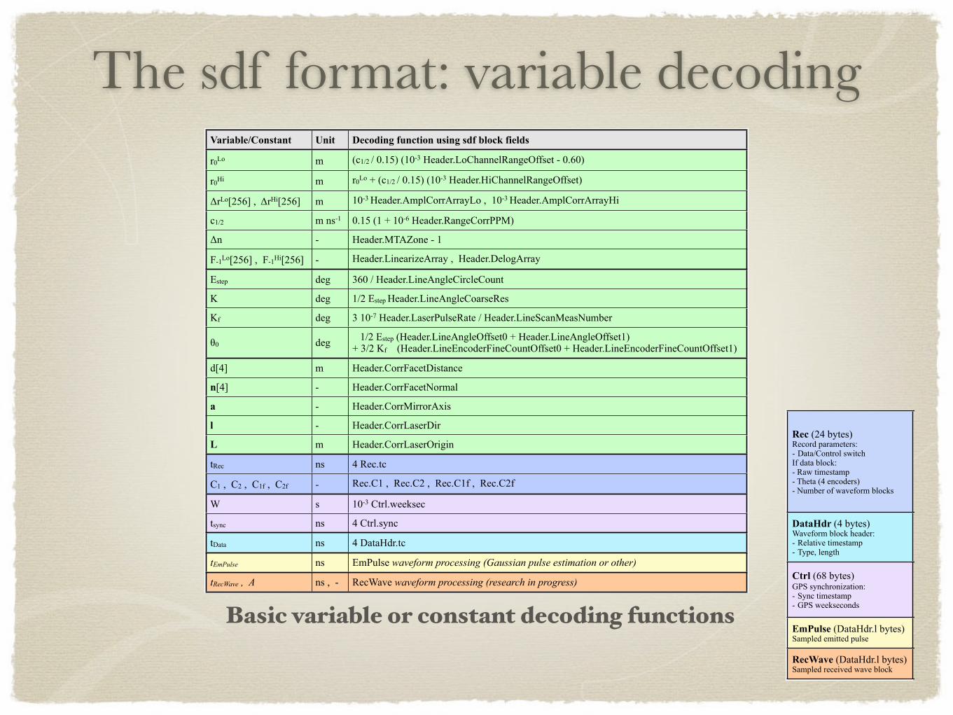
The sdf format: variable decodingVariable/Constant Unit Decoding function using sdf block fields
r0Lo m (c1/2 / 0.15) (10-3 Header.LoChannelRangeOffset - 0.60)
r0Hi m r0Lo + (c1/2 / 0.15) (10-3 Header.HiChannelRangeOffset)
ΔrLo[256] , ΔrHi[256] m 10-3 Header.AmplCorrArrayLo , 10-3 Header.AmplCorrArrayHi
c1/2 m ns-1 0.15 (1 + 10-6 Header.RangeCorrPPM)
Δn - Header.MTAZone - 1
F-1Lo[256] , F-1Hi[256] - Header.LinearizeArray , Header.DelogArray
Estep deg 360 / Header.LineAngleCircleCount
K deg 1/2 Estep Header.LineAngleCoarseRes
Kf deg 3 10-7 Header.LaserPulseRate / Header.LineScanMeasNumber
θ0 deg 1/2 Estep (Header.LineAngleOffset0 + Header.LineAngleOffset1)+ 3/2 Kf (Header.LineEncoderFineCountOffset0 + Header.LineEncoderFineCountOffset1)
d[4] m Header.CorrFacetDistance
n[4] - Header.CorrFacetNormal
a - Header.CorrMirrorAxis
l - Header.CorrLaserDir
L m Header.CorrLaserOrigin
tRec ns 4 Rec.tc
C1 , C2 , C1f , C2f - Rec.C1 , Rec.C2 , Rec.C1f , Rec.C2f
W s 10-3 Ctrl.weeksec
tsync ns 4 Ctrl.sync
tData ns 4 DataHdr.tc
tEmPulse ns EmPulse waveform processing (Gaussian pulse estimation or other)
tRecWave , A ns , - RecWave waveform processing (research in progress)
Rec (24 bytes)Record parameters:- Data/Control switchIf data block:- Raw timestamp- Theta (4 encoders)- Number of waveform blocks
struct Q680RecBlockBuf { char dum0 [2]; // -- char ctrl [1]; // u1 control block flag char tc [5]; // i5 record timestamp (4ns) char dum1 [2]; // -- char C1f [2]; // u2 fine angle encoder 1 char C1 [2]; // u2 coarse angle encoder 1 char dum2 [2]; // -- char C2f [2]; // u2 fine angle encoder 2 char C2 [2]; // u2 coarse angle encoder 2 char dum3 [3]; // -- char nb [1]; // u1 number of data blocks};
DataHdr (4 bytes)Waveform block header:- Relative timestamp- Type, length
struct Q680DataBlockHdrBuf { char tc [2]; // u2 data timestamp (4ns) char type [1]; // u1 type {EM=192, LO=0, HI=64} char l [1]; // u1 length (4 samples)};
Ctrl (68 bytes)GPS synchronization:- Sync timestamp- GPS weekseconds
struct Q680CtrlBlockBuf { char dum0 [51]; // -- char sync [5]; // i5 sync timestamp (4ns) char weeksec[4]; // u4 weekseconds (ms) char dum1 [8]; // --};
EmPulse (DataHdr.l bytes)Sampled emitted pulse
char EmPulse[DataHdr.l]; // u emitted pulse (1ns sampling)
RecWave (DataHdr.l bytes)Sampled received wave block
char RecWave[DataHdr.l]; // u received wave block (1ns sampling)
Basic variable or constant decoding functions
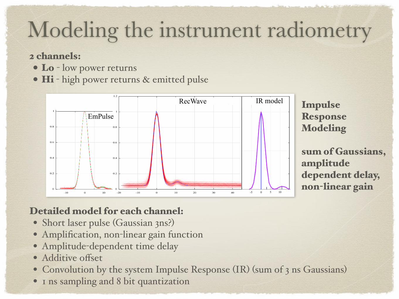
Modeling the instrument radiometry
IR modelRecWave
0 5-5 10
EmPulseImpulseResponseModeling
sum of Gaussians,amplitudedependent delay,non-linear gain
2 channels: • Lo - low power returns• Hi - high power returns & emitted pulse
Detailed model for each channel:• Short laser pulse (Gaussian 3ns?)• Amplification, non-linear gain function• Amplitude-dependent time delay• Additive offset• Convolution by the system Impulse Response (IR) (sum of 3 ns Gaussians)• 1 ns sampling and 8 bit quantization
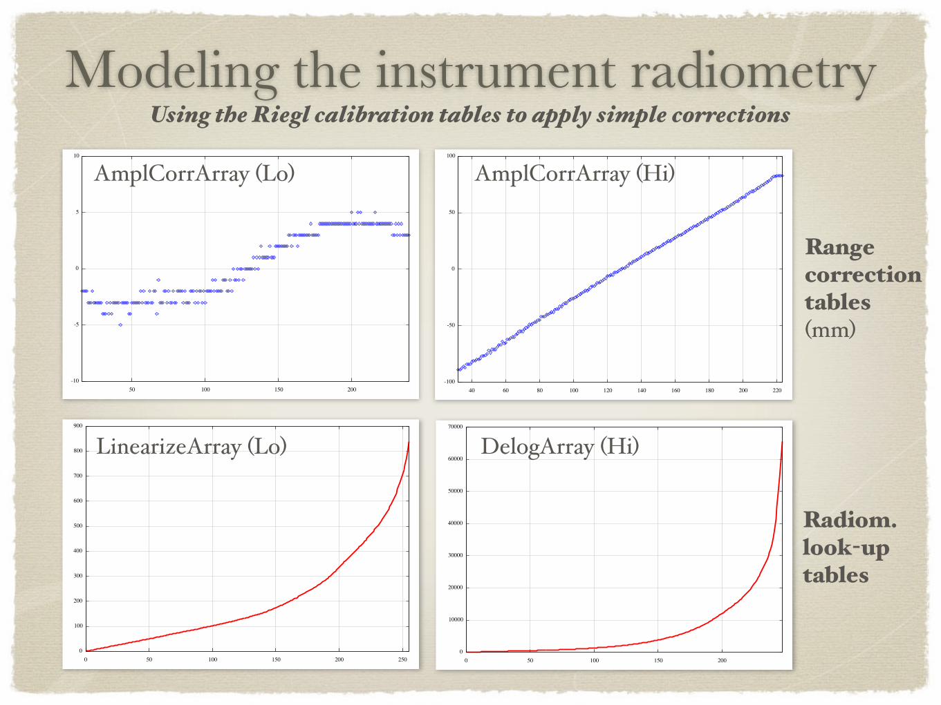
LinearizeArray (Lo) DelogArray (Hi)
Radiom.look-up tables
Modeling the instrument radiometry
AmplCorrArray (Lo) AmplCorrArray (Hi)
Rangecorrection tables(mm)
Using the Riegl calibration tables to apply simple corrections
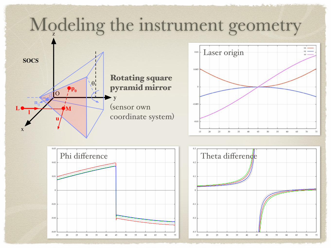
Modeling the instrument geometry
y
x
z
O
L lnθ
u
SOCS
θp0
M
d
Laser origin
Phi difference Theta difference
Rotating squarepyramid mirror
(sensor own coordinate system)
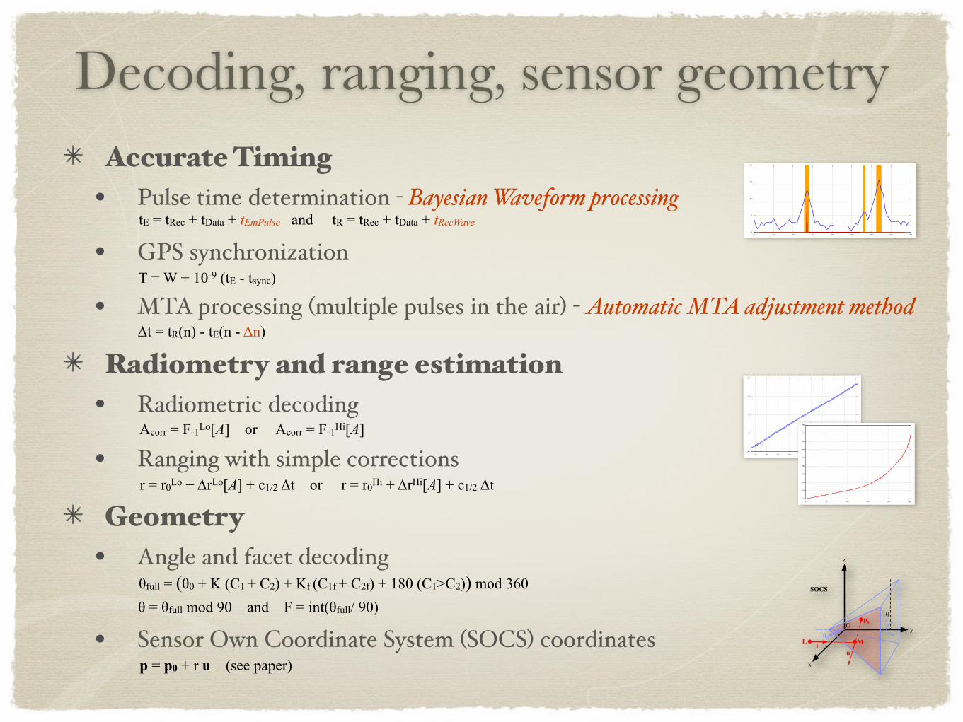
Accurate Timing• Pulse time determination - Bayesian Waveform processing
• GPS synchronization
• MTA processing (multiple pulses in the air) - Automatic MTA adjustment method
Radiometry and range estimation• Radiometric decoding
• Ranging with simple corrections
Geometry• Angle and facet decoding
• Sensor Own Coordinate System (SOCS) coordinates
Decoding, ranging, sensor geometry
tE = tRec + tData + tEmPulse and tR = tRec + tData + tRecWave
T = W + 10-9 (tE - tsync)
Δt = tR(n) - tE(n - Δn)
Acorr = F-1Lo[A] or Acorr = F-1Hi[A]
r = r0Lo + ΔrLo[A] + c1/2 Δt or r = r0Hi + ΔrHi[A] + c1/2 Δt
θfull = (θ0 + K (C1 + C2) + Kf (C1f + C2f) + 180 (C1>C2)) mod 360θ = θfull mod 90 and F = int(θfull/ 90)
p = p0 + r u (see paper)
y
x
z
O
L lnθ
u
SOCS
θp0
M
d
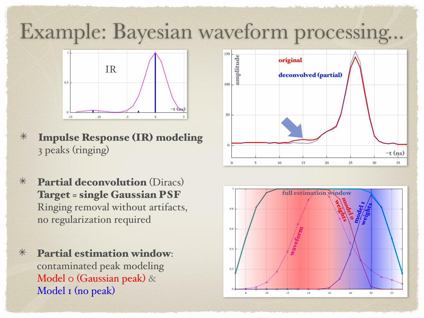
Impulse Response (IR) modeling3 peaks (ringing)
Example: Bayesian waveform processing...
Partial deconvolution (Diracs)Target = single Gaussian PSFRinging removal without artifacts, no regularization required
original
deconvolved (partial)
–t (ns)
ampl
itud
e
–t (ns)
IR
wav
efor
m
full estimation window
mod
el 1
wei
ghts
model 0
weights
Partial estimation window: contaminated peak modelingModel 0 (Gaussian peak) & Model 1 (no peak)
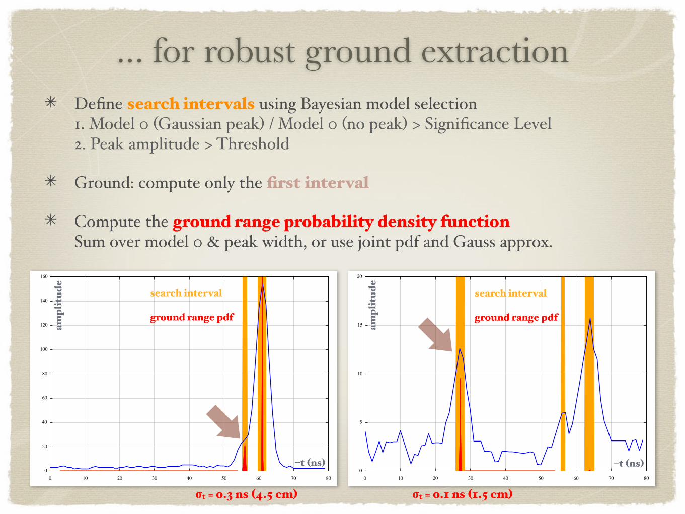
Define search intervals using Bayesian model selection1. Model 0 (Gaussian peak) / Model 0 (no peak) > Significance Level2. Peak amplitude > Threshold
Ground: compute only the first interval
Compute the ground range probability density functionSum over model 0 & peak width, or use joint pdf and Gauss approx.
... for robust ground extraction
–t (ns)–t (ns)
ampl
itud
e
ampl
itud
e
search interval
ground range pdf
search interval
ground range pdf
σt = 0.1 ns (1.5 cm)σt = 0.3 ns (4.5 cm)
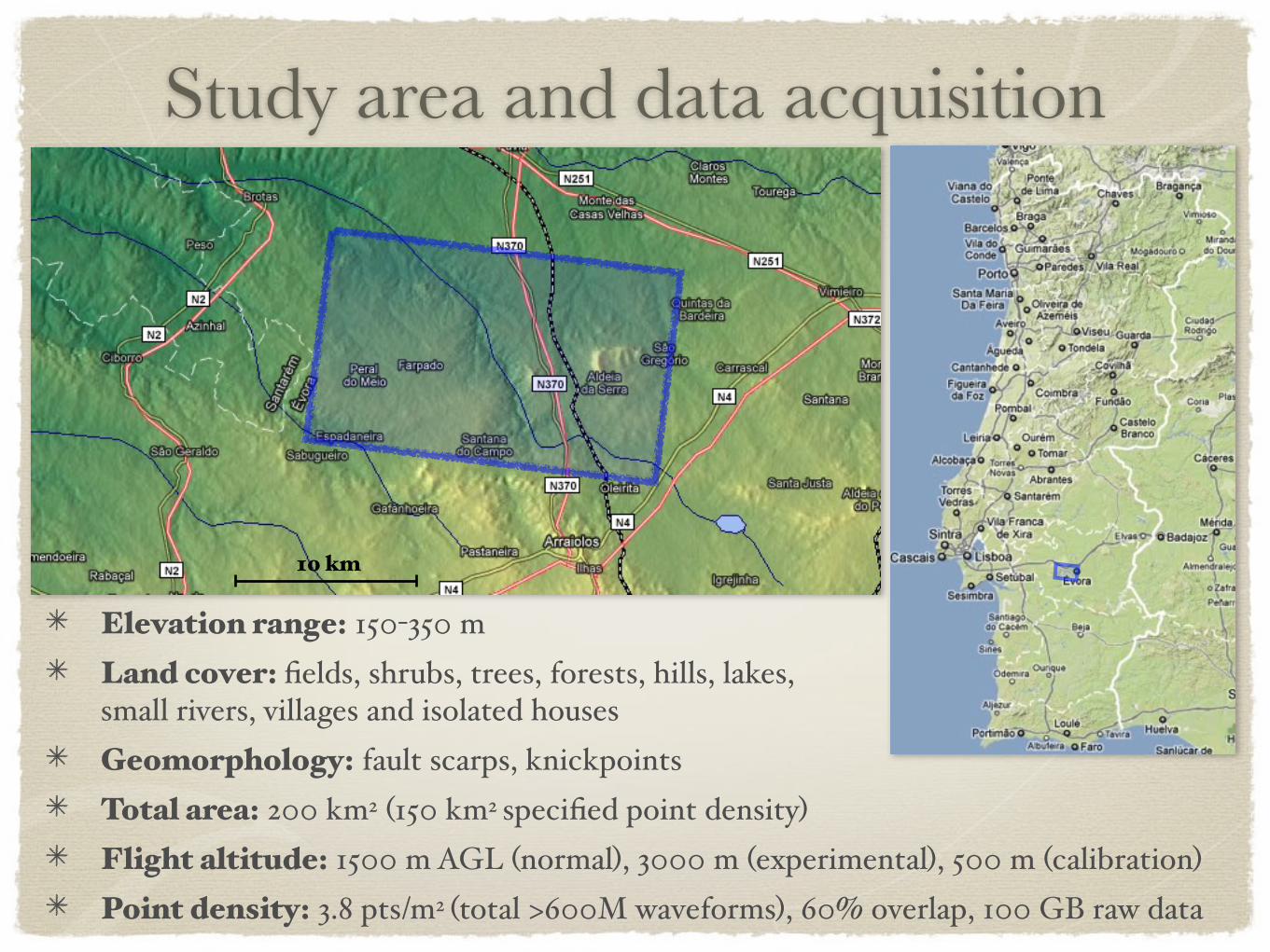
Study area and data acquisition
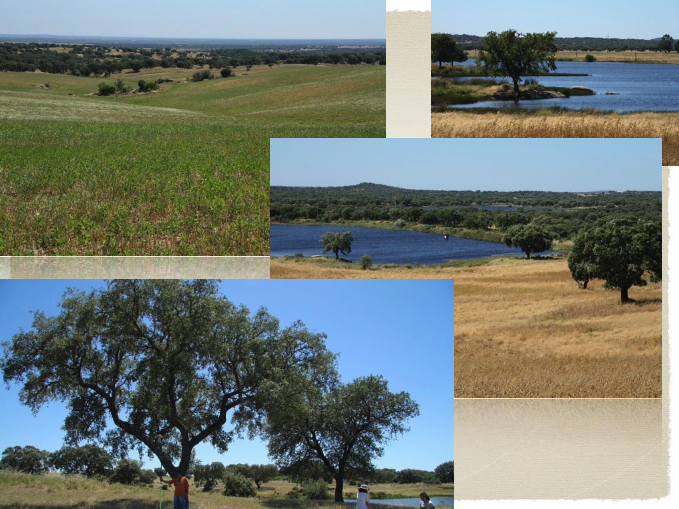
Elevation range: 150-350 mLand cover: fields, shrubs, trees, forests, hills, lakes,small rivers, villages and isolated housesGeomorphology: fault scarps, knickpointsTotal area: 200 km2 (150 km2 specified point density)Flight altitude: 1500 m AGL (normal), 3000 m (experimental), 500 m (calibration)Point density: 3.8 pts/m2 (total >600M waveforms), 60% overlap, 100 GB raw data
NW of Arraiolos, Portugal
10 km
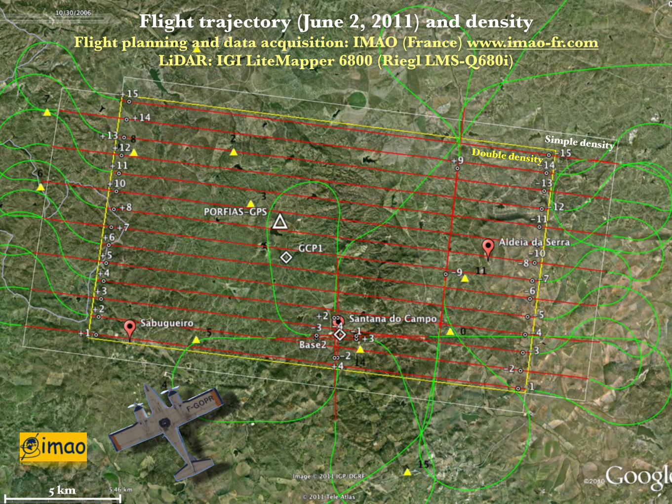
Flight trajectory (June 2, 2011) and densityFlight planning and data acquisition: IMAO (France) www.imao-fr.com
LiDAR: IGI LiteMapper 6800 (Riegl LMS-Q680i)
Double density
Simple density
5 km
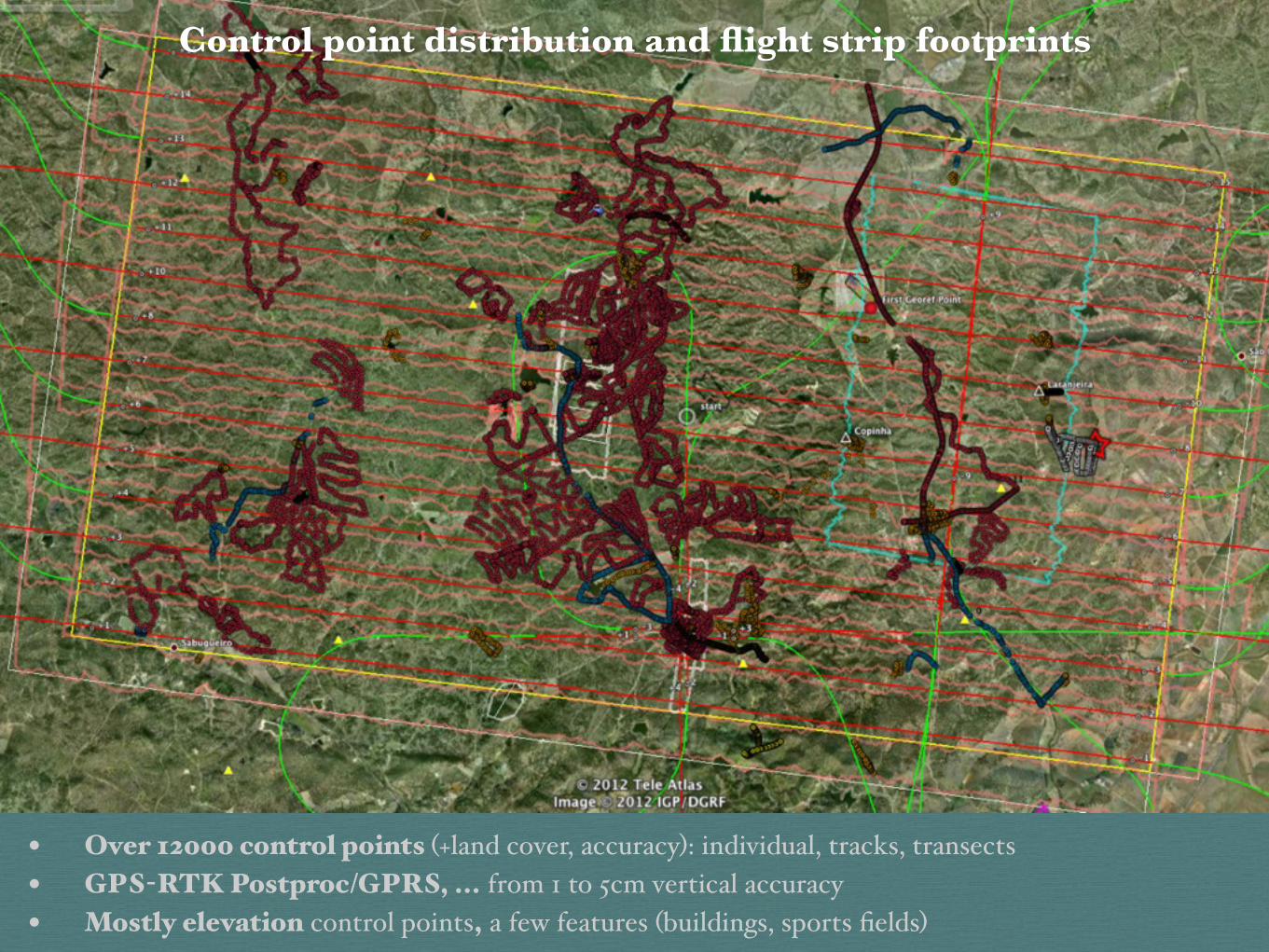
• Over 12000 control points (+land cover, accuracy): individual, tracks, transects• GPS-RTK Postproc/GPRS, ... from 1 to 5cm vertical accuracy• Mostly elevation control points, a few features (buildings, sports fields)
Control point distribution and flight strip footprints
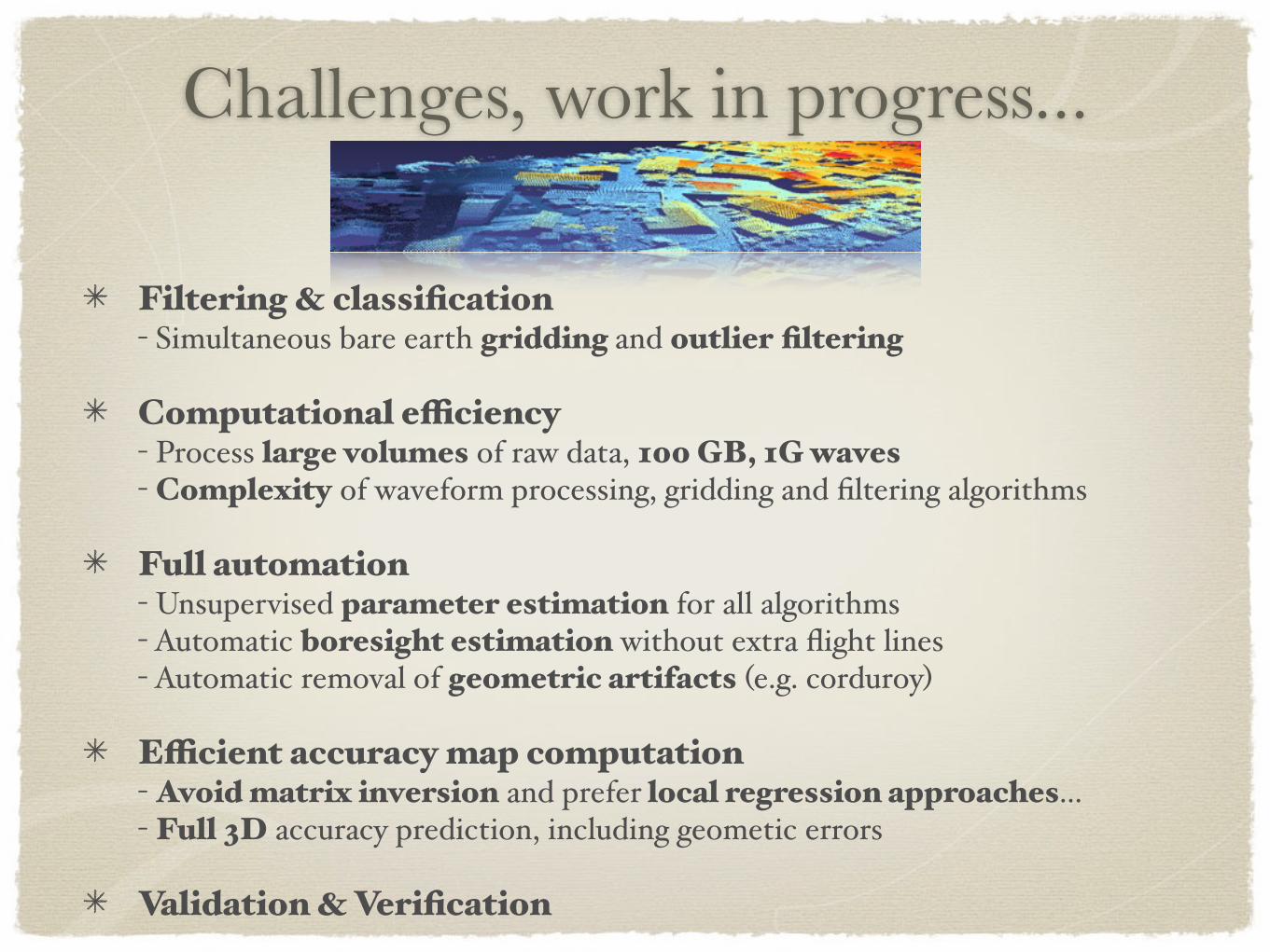
Filtering & classification- Simultaneous bare earth gridding and outlier filtering
Computational efficiency- Process large volumes of raw data, 100 GB, 1G waves- Complexity of waveform processing, gridding and filtering algorithms
Full automation- Unsupervised parameter estimation for all algorithms- Automatic boresight estimation without extra flight lines- Automatic removal of geometric artifacts (e.g. corduroy)
Efficient accuracy map computation- Avoid matrix inversion and prefer local regression approaches...- Full 3D accuracy prediction, including geometic errors
Validation & Verification
Challenges, work in progress...
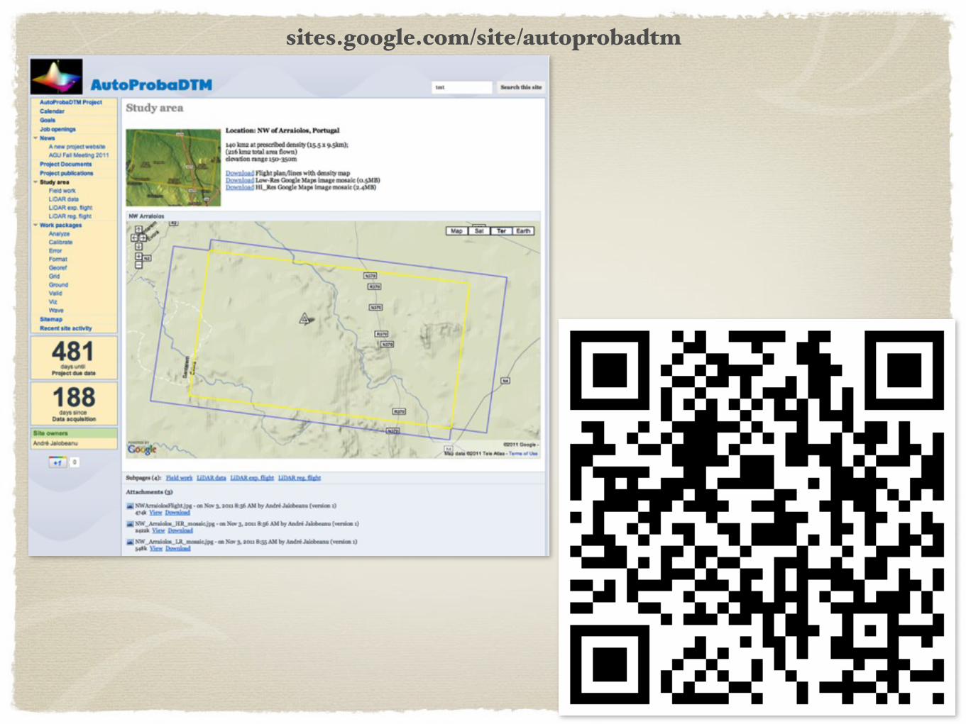
sites.google.com/site/autoprobadtm