Embed Size (px)
Citation preview

The Four Boolean Operations (draft 1, 3/10/06)
Introduction
SolidWorks frequently employs Boolean operations when building solid bodies. Commands like Extrude, Cut, Loft, Loft Cut, etc frequently perform Boolean operations, but do not state them in that context. For more complicated shapes sometimes one needs to specific commands available when the above standard commands can not easily build the part you need. SolidWorks refers to them as “Combine” operations and names them common, add, and subtract, respectively.
The corresponding Boolean operations of intersection and union are commutative (that is, the order of selection of the two bodies does not matter). However, the difference operation is not commutative and can be utilized in two ways. Therefore, this demonstration will illustrate using all four ways. It is common to have to use those operations. However, SolidWorks makes them quite hard to find by not including the word “Boolean” anywhere in its massive on-line help file. The help file does have an image of the results from the four combine operations. But it does not give a tutorial on the numerous steps needed to get the parts together, mate them in the desired positions, and to finally carry out the Boolean operation. This demonstration will do that.
Basically, at a minimum you should have at lease two original parts created and saved as parts. (Alternatively, you could create two solid parts in a single part file.) Then one of the parts is opened and another is inserted to form a new “multipart” (which is found in the Help file). That is not an assembly. In this example, one body will be an elliptical extrusion of one thickness, and a brick with a different thickness. They are shown in Figure 1. The steps to create each body are given in Appendices A and B, respectively at the end of this document. The back center point of the ellipse will be combined with a lower back corner of the brick. The same resultant shape could be created with the usual extrude and cut operations. The focus here is on documenting the process for Boolean operations when more complicated shapes are involved.
Figure 1 Two shaved solids to be combined
Page 1 of 11. Copyright J.E. Akin. All rights reserved.

Creating a multipart
Assuming that you have built (or copied) the two parts in Appendices A and B, open SolidWorks to create other parts by using Boolean operations:
1. NewPartOK2. FileOpenBrowse select Boolean_ellipse.SLDPRTOpen. You now have a standard
part open.3. Now bring in a second part to form a multipart: InsertPartBrowse select
Boolean_brick.SLDPRTOpen, as seen in Figure 2.4. The Insert Part panel appears. Drag the part to be close to the elliptical slab (Figure 3).
Figure 2 Selecting an additional part to form a multipart file
Figure 3 Positioning the second part for relative movement
Page 2 of 11. Copyright J.E. Akin. All rights reserved.

Mate two bodies to set up Boolean operations
Now that you have the two bodies in the same multipart file, one needs to be specifically located relative to the other so that you can carry out the desired Boolean operation. When SolidWorks detects at least two solids in the same file it lists the number present, after the Solids section, in the Feature Menu. The next task is to move one body relative to the next, and mate them if desired via:
1. At the bottom of the Locate Part panel select the Translate/Rotate option. Here the option of specifying movement in increments of the global coordinates is not illustrated. Instead, the use of construction geometry an mating operations are employed.
2. In that sub-region of the Locate Part panel select the Constraints option to apply mates for placing the bodies in the position needed for the Boolean operation (see Figure 4).
Figure 4 Preparing to use geometrical mates of the two parts
3. That takes you to the Mate Settings of the Locate Part panel. To make the two back faces coincident select them so they appear in the Mate Setting list, check the Coincident box, as seen in Figure 5.
4. Finally check Add, OK. You see the second body move to make their back planes co-planar, and the constraint appears in the lower list of the Locate Part panel.
To proceed with necessary translations (or rotation for other mates) it is necessary to add some construction lines on the surface of the elliptical solid. To do that:
1. Select the desired face with a right clickInsert Sketch.2. Select centerline from the Sketch Menu.3. Move the cursor to the center of the ellipse to “wake up” that point to provide guidance lines as
you insert each centerline.4. Place centerlines along the major and minor axes of the ellipse, as in Figure 6.5. Close the sketch.
Page 3 of 11. Copyright J.E. Akin. All rights reserved.

Figure 5 Locate two planes coincident and mate them
Figure 6 Place construction geometry on the fixed body
Now you can proceed with moving the brick in the common plane to mate with the construction lines on the elliptical body. Use
1. InsertFeaturesMove/Copy to open the Move/Copy Body panel.2. Click in the Bodies to Move/Copy list and select the brick body.3. Turn off the Copy button.4. Pick the Constraints option to apply mates for placing the bodies (see Figure 7).
Page 4 of 11. Copyright J.E. Akin. All rights reserved.
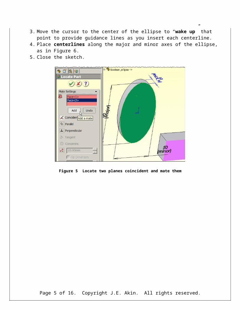
Figure 7 Select the option to move a body and optionally mate it
Next you need to align a pair of geometric entities (one from each body):1. In the Move/Copy Body panel click in the Bodies to Move list area and select the brick.2. In the Mate Settings list area first pick the longer line on the brick at the desired mating point,
as illustrated in the top of Figure 8. The name of the line appears in the Mate Settings list area.3. Now pick the line on the fixed body, select a Coincident mate, and Add.4. You will see the first body move to make the lines coincident (again in Figure 9), if you have
Preview turned on. When you agree that the result is correct pick OK.
Of course, you are not restricted to using lines as the reference geometry. To finalize the positioning the two parts by the mating process repeat the last process by picking the short edge of the brick at the desired vertex and the major axis of the ellipse (see Figure 9). Make them coincident, preview the resultant relative orientation and accept when correct. The final relative orientations are seen in Figure 10. If you have not done, so it is helpful to change the color of one of the bodies. That lets you better visualize the final result of any Boolean (Combine) operation.
While the two solids may look like they have been joined, they are still two separate bodies. The above mate operations were just to position one body relative to the other. At this point we bodies are in the required position and you can invoke a Boolean operation to form the final new single part. This is a good place to save the orientated pair with a new name.
Page 5 of 11. Copyright J.E. Akin. All rights reserved.

Figure 8 Align and mate the first pair of orientation lines
Figure 9 Select and mate a second pair of orientation geometries
Page 6 of 11. Copyright J.E. Akin. All rights reserved.
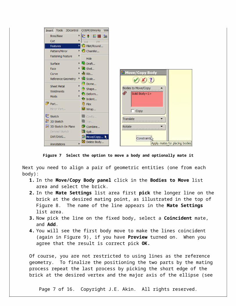
Figure 10 Final orientations before a Boolean operation
Example Boolean (combine) operations
CommonHaving saved the orientated pair of bodies they can be reused to illustrate each of the combine operations. The first example will be for the Common (intersection) set. For two bodies, say A and B, the result, say C, is expressed as C = A ∩ B = B ∩ A, where C is the object that contains all points that are common to both A and B. To create the intersection:
1. Use InsertFeaturesCombine to open a Combine(#) panel.2. There select the Operation Type as Common. Since the order of body selection is
independent for that option, only a single Bodies to Combine list appears.3. Click in that list area and select the brick body (A), as seen in Figure 11, so its name appears in
the list.4. Pick the second (elliptical) body (B) to add it to the list.5. When all the desired bodies have been inserted into the list click OK and the result (C) of the
Boolean intersection (combine) will appear in the graphics area, as also seen in Figure 11.6. Save and assign it a new name.
Subtract
Next, consider the SolidWorks subtract operations (Boolean differences). Denote that operation as C = A – B ≠ B – A as the object C that remains when any points common to A and B are removed from A. Clearly, the order in which the objects are picked determines the result. In other words, (A – B) and (B – A) give different results. Starting again with the two oriented bodies of Figure 10 you carry out a series of similar steps for the difference operator:
1. Use InsertFeaturesCombine to open a Combine(#) panel.2. There select the Operation Type as Subtract. Since the order of body selection is important
for that option, two different lists appear: the Main Body panel (A), and (B) the Bodies to Subtract.
Page 7 of 11. Copyright J.E. Akin. All rights reserved.

Figure 11 The common (intersection) operation and result (lower right)
3. If you click in the Main Body panel and select the elliptical extrusion (A), and then click in the Bodies to Subtract list and, pick the brick body (B) as the second object then you obtain the offset ‘C’ shaped body seen in the top right of Figure 12.
4. Conversely, if you click in the Main Body panel and select the brick body (A), and then click in the Bodies to Subtract list and, pick the elliptical extrusion (B) as the second object then you obtain the curved notch brick seen at the bottom of Figure 12.
5. Save whichever option you need and assign it a new name.
Page 8 of 11. Copyright J.E. Akin. All rights reserved.

Figure 12 Two options for the subtract (Boolean difference) operation
Add
The final SolidWorks combining operation is named Add. It is the Boolean union operation and is denoted as C = A U B = B U A where C is the object that contains all points originally in A or B.To create the union of two bodies
1. Use InsertFeaturesCombine to open a Combine(#) panel.2. There select the Operation Type as Add. Since the order of body selection is independent for
that option, only a single Bodies to Combine list appears.3. Click in that list area and select the brick body (A), so its name appears in the list.4. Pick the second (elliptical) body (B) to add it to the list.5. When all the desired bodies have been inserted into the list click OK and the result (C) of the
Boolean union (add) will appear in the graphics area, as also seen in Figure 13.6. Save and assign it a new name
Page 9 of 11. Copyright J.E. Akin. All rights reserved.

Figure 13 The Add operation (Boolean union) for two bodies
As seen in Figure 10 it is often useful to assign the different colors to the bodies to be combined. The result of the add operation (union) looks like the original bodies in this example. Assign the resulting object a new color to verify that it is a single object:
1. Right click on any of its surfaces.2. In the pop up options list pick BodyAppearanceColor. See Figure 14.3. When the Color and Optics panel appears select the desired color, OK. A correct union
operation should display the same color everywhere.
Figure 14 Changing the color of a single body
Page 10 of 11. Copyright J.E. Akin. All rights reserved.
Appendix A
Figure 15
Appendix B
Page 11 of 11. Copyright J.E. Akin. All rights reserved.