Embed Size (px)
Citation preview
The Formalism Transformation Graphas a Guide to Model Driven Engineering
Levi Lucio†, Sadaf Mustafiz†, Joachim Denil‡,Bart Meyers‡, Hans Vangheluwe‡†
†School of Computer Science, McGill University, Canada ??
‡University of Antwerp, Belgium{levi,sadaf,hv}@cs.mcgill.ca
{Joachim.Denil,Bart.Meyers,Hans.Vangheluwe}@ua.ac.be
Abstract. In recent years, many new concepts, methodologies, and toolshave emerged, which have made Model Driven Engineering (MDE) moreusable, precise and automated. A MDE process is very often dependenton the domain. Thus, means for composing and customizing MDE activ-ities are increasingly necessary. In this paper, we propose the FTG+PMframework that acts as a guide for carrying out model transformations,and as a basis for unifying key MDE practices, namely multi-paradigmmodelling, meta-modelling, and model-transformation. The FTG+PMconsists of the Formalism Transformation Graph (FTG) and its com-plement, the Process Model (PM), and charts all kinds of activities inthe MDE lifecycle such as requirements development, domain-specificdesign, verification, simulation, analysis, calibration, deployment, codegeneration, execution, etc. The FTG describes in an explicit and pre-cise way, formalisms, and their relationships as transformations betweenformalisms. The PM defines an actual MDE process using these for-malisms and transformations. We illustrate the proposed FTG+PM ap-proach through the design of an automated power window, a case studyfrom the automotive domain.
1 Introduction
In recent times, model driven engineering (MDE) has been adopted in industrialprojects in widely varying domains. The promises of MDE regarding traditionalsoftware development methods are many. The most important ones are: bettermanagement of the complexity of software development by making use of power-ful abstractions; better management of the requirements for the system comingfrom the stakeholders, by both exposing the logic of the system in languagesthat are understandable by non programmers as well as fast re-generation ofcode by using automated model transformations; less bugs in the final softwareproduct given that automation helps eliminate errors and usage of formal verifi-cation tools raises confidence of correctness; and finally automated documenta-tion generation from domain specific models. If achieved, all these benefits would
?? Part of this work has been developed in the context of the NECSIS project, fundedby the Automotive Partnership Canada
translate in potentially faster, cheaper and more reliable software developmenttechniques than the ones traditionally used.
Several important concepts and associated fields of study have emerged orhave been adopted and further developed by the efforts of the MDE commu-nity. Model transformations, domain specific modelling, requirements engineer-ing, verification and validation, multi-paradigm modelling, model composition,simulation, calibration, deployment, code generation, etc. are often proposed inthe form of tools, methodologies or frameworks to help alleviate issues in theapplication of MDE. However, to the best of our knowledge, the challenges andbenefits arising from the conjugation and synergies of all these concepts duringthe application of MDE are yet to be explored. This is partially due to the factthat most of the tools, methodologies or frameworks proposed by the communityoften focus in-depth on technically challenging issues, while the broader pictureof the systematic integration of those technical and methodological solutions re-mains, for the time being, to be explored. An additional difficulty often facedby MDE researchers is the limited access to the software development tools,methodologies and models used in real industrial settings. This is often due tothe fact that companies that do apply MDE techniques during software develop-ment do not want to expose their development processes or data either by fearof loss of competitive edge, or simply by lack of time and resources to share theirknow-how.
The goal of our work is to provide a complete and detailed process archi-tecture for model-driven software development by unifying key MDE practices.We propose FTG+PM framework intended to guide developers throughout theMDE lifecycle. The FTG+PM is comprised of the Formalism TransformationGraph (FTG) and its complement, the Process Model (PM). The idea behindthe FTG is similar to the Formalism Transformation Lattice for coupling differ-ent formalisms as proposed by Vangheluwe et al in [45]. We go a step beyondmulti-formalism modelling, and use the notion of multi-paradigm modelling [31]as the basis of our work. Model transformation is a key element in our FTG+PM.Our FTG+PM addresses the need for domain-specific modelling, and an instanceof the FTG includes domain-specific formalisms and transformations betweenthem that allow capturing a map of the process used to develop software withina given domain. The PM introduced as part of the FTG+PM can be used toprecisely model the control flow between the transformation activities takingplace throughout the software development lifecycle starting from requirementsanalysis and design to verification, simulation, and deployment.
We have worked with automotive systems as our target domain, but we be-lieve that the FTG+PM can be applied in general in a broad range of domains. Inparticular, we demonstrate the capabilities of the FTG+PM through the designof an automated power window. The case study is of inherent complexity, non-trivial in nature, and representative of industrial case studies. The formalismsused in the FTG are appropriate to the levels of abstraction used at differentstages of the modelling process. Discrete-time, continuous-time, discrete-event,and hybrid formalisms are included. The MDE process is entirely based on mod-
els and transformations, starting from domain specific requirements and designmodels aimed at describing control systems and their environment and finishingwith Automotive Open System Architecture (AUTOSAR) [4] code.
This paper is organised as follows: Section 2 provides background informa-tion on meta-modelling, model transformation, and multi-paradigm modelling.Section 3 describes the FT&P and illustrates it using the power window casestudy. Section 4 gives a formal definition of the formalism transformation graph(FTG) and the process model (PM). Section 5 discusses our contibutions andpossible improvements of FTG+PM. Section 6 presents related work in this areaand compares our contribution to it and Section 7 draws some conclusions.
2 Background
Model Driven Engineering (MDE) encompasses both a set of tools and a method-ological approach to the development of software. MDE advocates building andusing abstractions of processes (and associated artefacts) the software engineer istrying to automate, thus making them easier to understand, verify, and simulatethan computer programs.
Within the context of this paper, we have chosen to follow the terminologyas presented in [17]). A model is completely described by its abstract syntax (itsstructure), concrete syntax (its visualisation) and semantics (its unique and pre-cise meaning). A language is a possibly infinite set of (abstract syntax) models.This set can be concisely described by means of e.g., a grammar or a metamodel.No semantics or concrete syntax is given to these models.
Domain Specific Modelling (DSM) captures the fact that certain languagesor classes of languages, called Domain Specific Languages (DSLs), are appropri-ate to describe models in certain domains. A white paper on the subject fromMetacaseTM [27] presents anecdotal evidence that DSLs can boost productivityby a factor of 10, based on experiences with developing operating systems forcell phones for NokiaTM and LucentTM . DSM has led to the development offormalisms and tools such as EMF and GMF [30], AToM3 [11] or Microsoft’sDSL ToolsTM [9].
Model transformations are the heart and soul of model-driven software de-velopment, as stated by Sendall and Kozaczynski [40]. Model transformationinvolves mapping of source models in one or more formalisms to target modelsin one or more formalisms using a set of transformation rules. Having an au-tomated process for creating and modifying models leads to reduced effort anderrors on the software engineer’s part.
Implementations for transformation languages such as ATL [2] or QVT [13],and for graph transformations (as used in AToM3) have been developed in thelast few years and provide stable platforms for describing and executing modeltransformations.
Multi-Paradigm Modelling (MPM), as introduced by Mosterman and Vangheluwein [31], is a perspective on systems development that advocates not only thatmodels should be built at the right levels of abstraction regarding their purpose,
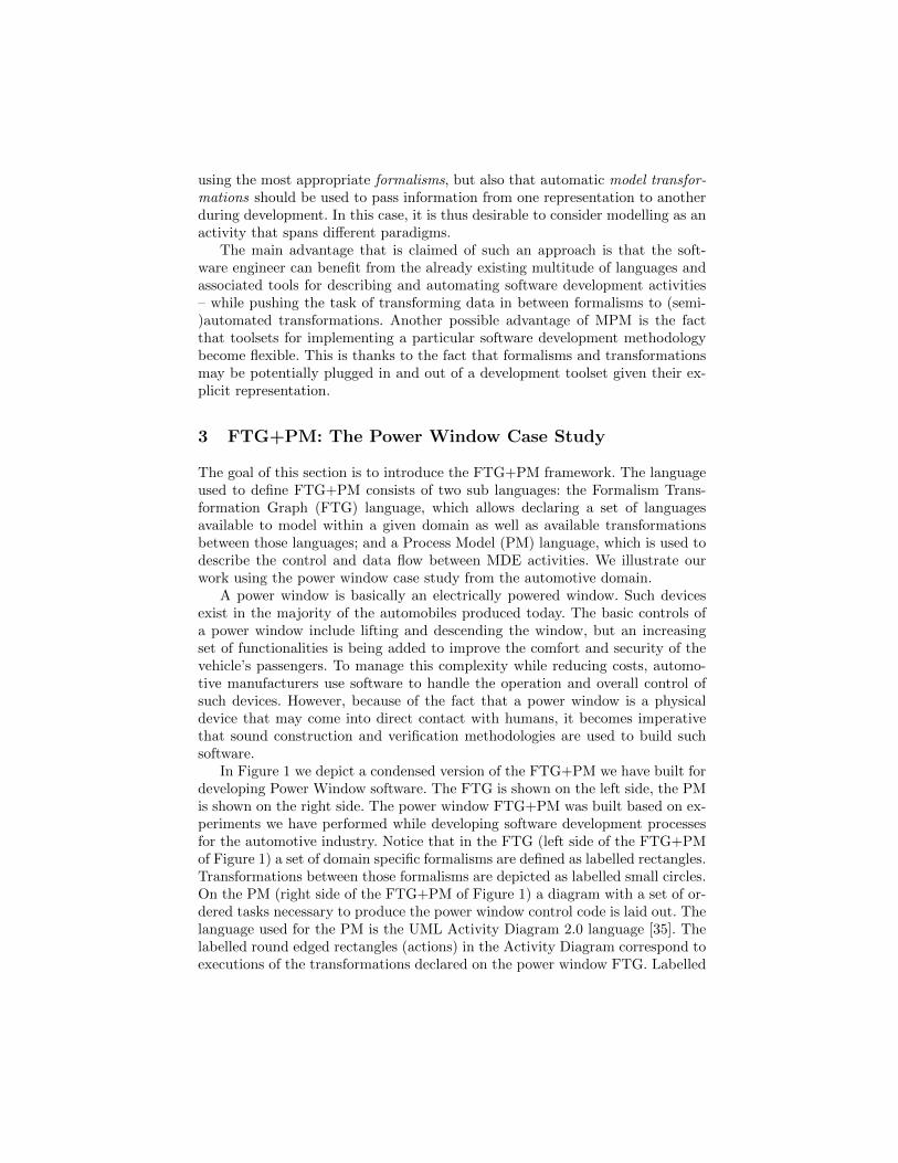
using the most appropriate formalisms, but also that automatic model transfor-mations should be used to pass information from one representation to anotherduring development. In this case, it is thus desirable to consider modelling as anactivity that spans different paradigms.
The main advantage that is claimed of such an approach is that the soft-ware engineer can benefit from the already existing multitude of languages andassociated tools for describing and automating software development activities– while pushing the task of transforming data in between formalisms to (semi-)automated transformations. Another possible advantage of MPM is the factthat toolsets for implementing a particular software development methodologybecome flexible. This is thanks to the fact that formalisms and transformationsmay be potentially plugged in and out of a development toolset given their ex-plicit representation.
3 FTG+PM: The Power Window Case Study
The goal of this section is to introduce the FTG+PM framework. The languageused to define FTG+PM consists of two sub languages: the Formalism Trans-formation Graph (FTG) language, which allows declaring a set of languagesavailable to model within a given domain as well as available transformationsbetween those languages; and a Process Model (PM) language, which is used todescribe the control and data flow between MDE activities. We illustrate ourwork using the power window case study from the automotive domain.
A power window is basically an electrically powered window. Such devicesexist in the majority of the automobiles produced today. The basic controls ofa power window include lifting and descending the window, but an increasingset of functionalities is being added to improve the comfort and security of thevehicle’s passengers. To manage this complexity while reducing costs, automo-tive manufacturers use software to handle the operation and overall control ofsuch devices. However, because of the fact that a power window is a physicaldevice that may come into direct contact with humans, it becomes imperativethat sound construction and verification methodologies are used to build suchsoftware.
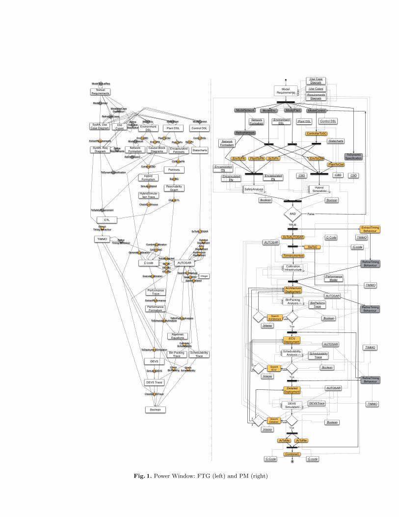
In Figure 1 we depict a condensed version of the FTG+PM we have built fordeveloping Power Window software. The FTG is shown on the left side, the PMis shown on the right side. The power window FTG+PM was built based on ex-periments we have performed while developing software development processesfor the automotive industry. Notice that in the FTG (left side of the FTG+PMof Figure 1) a set of domain specific formalisms are defined as labelled rectangles.Transformations between those formalisms are depicted as labelled small circles.On the PM (right side of the FTG+PM of Figure 1) a diagram with a set of or-dered tasks necessary to produce the power window control code is laid out. Thelanguage used for the PM is the UML Activity Diagram 2.0 language [35]. Thelabelled round edged rectangles (actions) in the Activity Diagram correspond toexecutions of the transformations declared on the power window FTG. Labelled
:ModelPlant :ModelControl:ModelEnv:ModelNetwork
:ControllerToSC
:ScToPn:PlantToPN:EnvToPN
:PlantToCbd
:EnvToCbd
AND False
:ScToAUTOSAR
:ToInstrumented
:ArchitectureDeployment
:ECUDeployment
False
True
:DetailedDeployment
False
True
:SwToC
:ArToRte:ArToMw
:CombineC
:RefineNetwork
:ToDynamicSpecification
TRUE:ExtractTiming
Behaviour
:RefineTimingBehaviour
:RefineTimingBehaviour
:RefineTimingBehaviour
True
:Boolean :Boolean
:Control DSL:Plant DSL:Environment DSL
:Network Formalism
:Statecharts
:CBD:Encapsulated PN
:CBD:Encapsulated PN
:Encapsulated PN
:Network Formalism
:AUTOSAR
:Performance Model
:AUTOSAR
:AUTOSAR
:AUTOSAR
:Boolean
:Boolean
:Boolean
:C-Code :C-code
:C-code
:C-Code
:Requirements Diagram
:CBD
:TIMMO
:TIMMO
:TIMMO
:TIMMO
ModelRequirements
SafetyAnalysis HybridSimulation
CalibrationInfrastructure
EnvToCBD
Environment DSL
Causal Block Diagrams
PlantToCbd
Plant DSL
ControlToSc
Control DSL
StatechartsNetwork
FormalismEncapsulated
Petrinets
Hybrid Formalism
CombineCBD
AUTOSAR
ScToAUTOSAR
C-code SwToC
Algebraic Equations
ToSchedulabilityAnalysis
DEVS
ToDeploymentSimulation
Performance Trace
ExecuteCalibration
Performance Formalism
ExtractPerformance
ToInstrumented
Architecture Deployment
ScToPnPlantToPnEnvToPN
CombinePN
Reachability Graph
HybridSimula-tion Trace
SimulateHybrid
BuildRG
ToBinPackingAnalysis
RefineNetwork
ModelPlant ModelControlModelEnv
ECUDeployment
DetailedDeployment
ModelNetwork
ArToMwArToRte
CcombineC
SysML Req Diagram
TIMMO
CTL
ModelContext
ExtractRequirements
ToSafetyRequirement
ToDynamicSpecification
Extract Timing Behaviour
Refine Timing Behaviour
SysML Use Case Diagram
Textual Requirements
ModelTextualReq
Boolean
CheckCTL
CheckContinuous
Petrinets
RefineUseCases
RefineRequirements
DEVS Trace
SimulateDEVS
Bin Packing Trace
CheckDEVSTrace
Schedulability Trace
CalculateSchedulability
CheckBinPacking
GenerateCalibration
CombineCalibration
RefineUseCase
Description
ModelUseCaseDescription
SearchECUSearchDetailed
CheckSchedulability
:Use Cases
:Use Case Diagram
:SearchECU
:SearchDetailed
:SearchArchitecture False
SchedulabilityAnalysis
DEVSSimulation
BinPackingAnalysis
SearchArchitectureInteger
:Integer
:Integer
:Integer
:BinPackingTrace
:SchedulabilityTrace
:DEVSTrace
1
2
2
1
3
1
Use Cases
Fig. 1. Power Window: FTG (left) and PM (right)
square edged rectangles (data objects) in the PM correspond to models thatare consumed or produced by actions. A model is an instance of the formalismsdeclared on the power window FTG with the same label. Notice that on thePM side the thin arrows indicate data flow, while thick arrows indicate controlflow. Similar to the models, the arrows must also have corresponding arrow inthe FTG, meaning that their input and output nodes must correspond. Similarto Activity Diagrams we also use control flow constructs for a PM like joins andforks, represented as horizontal bars, and decisions, represented by diamonds.The formalised meaning of the FTG+PM will be presented in depth in Section 4.
The power window FTG+PM of Figure 1 contains several phases, that aresometimes executed in parallel. These contain (1) Requirements Engineering,(2) Design, (3) Verification, (4) Simulation, (5) Calibration, (6) Deployment andfinally (7) Code Generation, which are described below. Due to this paper’s spaceconstraints we provide detailed descriptions of only verification and deployment.However, most of the languages defined within the FTG+PM for the powerwindow, with the exception of requirements, has been described in [24].
3.1 Requirements Engineering
Before any design activities can start, the requirements need to be formalisedso they can be used by the engineers. Starting from the textual description con-taining the features and constraints of the power window, a context diagram ismodelled using the SysML use case diagram. The use cases are further refinedand complimented with the use case descriptions. Finally, the requirements arecaptured more formally with a SysML requirements diagram. Note that thesetransformations are usually done manually by the requirements engineers thoughsome automatic transformations can be used to populate the use case diagramand requirements diagram. The manual transformations are shown greyed outin the FTG.
3.2 Design
When given the task to build the control system for a power window, engineerswill take two variables into consideration: (1) the physical power window itself,which is composed of the glass window, the mechanical lift, the electrical engineand some sensors for detecting for example window position or window collisionevents; (2) the environment with which the system (controller plus power win-dow) interacts, which will include both human actors as well as other subsystemsof the vehicle – e.g. the central locking system or the ignition system. This ideais the same as followed by Mosterman and Vangheluwe in [31]. According to con-trol theory [12], the control software system acts as the controller, the physicalpower window with all its mechanical and electrical components as the process(also called the plant), and the human actors and other vehicle subsystems asthe environment.
:BuildRG
:CombinePN
:CheckReachableState
:Boolean
:Petri-Net
:Reachability Graph
:CTL
:Requirements Diagram
:Encapsulated PN
:Encapsulated PN
:Encapsulated PN
Encapsulated Petrinets
combinePN
Reachability Graph
BuildRG
CTL
ToSafetyRequirement
CheckReachableState
Petrinets
Boolean
:Network Formalism
:ToSafetyReq
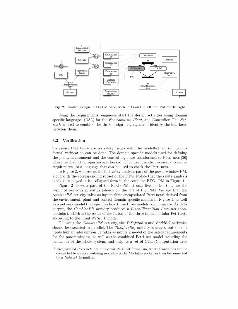
Fig. 2. Control Design FTG+PM Slice, with FTG on the left and PM on the right
Using the requirements, engineers start the design activities using domainspecific languages (DSL) for the Environment, Plant, and Controller. The Net-work is used to combine the three design languages and identify the interfacesbetween them.
3.3 Verification
To assure that there are no safety issues with the modelled control logic, aformal verification can be done. The domain specific models used for definingthe plant, environment and the control logic are transformed to Petri nets [36]where reachability properties are checked. Of course it is also necessary to evolverequirements to a language that can be used to check the Petri nets.
In Figure 2, we present the full safety analysis part of the power window PM,along with the corresponding subset of the FTG. Notice that the safety analysisblock is displayed in its collapsed form in the complete FTG+PM in Figure 1.
Figure 2 shows a part of the FTG+PM. It uses five models that are theresult of previous activities (shown on the left of the PM). We see that thecombinePN activity takes as inputs three encapsulated Petri nets1 derived fromthe environment, plant and control domain specific models in Figure 1, as wellas a network model that specifies how those three models communicate. As dataoutput, the CombinePN activity produces a Place/Transition Petri net (non-modular), which is the result of the fusion of the three input modular Petri netsaccording to the input Network model.
Following the CombinePN activity, the ToSafetyReq and BuildRG activitiesshould be executed in parallel. The ToSafetyReq activity is greyed out since itneeds human intervention. It takes as inputs a model of the safety requirementsfor the power window, as well as the combined Petri net model including thebehaviour of the whole system, and outputs a set of CTL (Computation Tree
1 encapsulated Petri nets are a modular Petri net formalism, where transitions can beconnected to an encapsulating module’s ports. Module’s ports can then be connectedby a Network formalism.
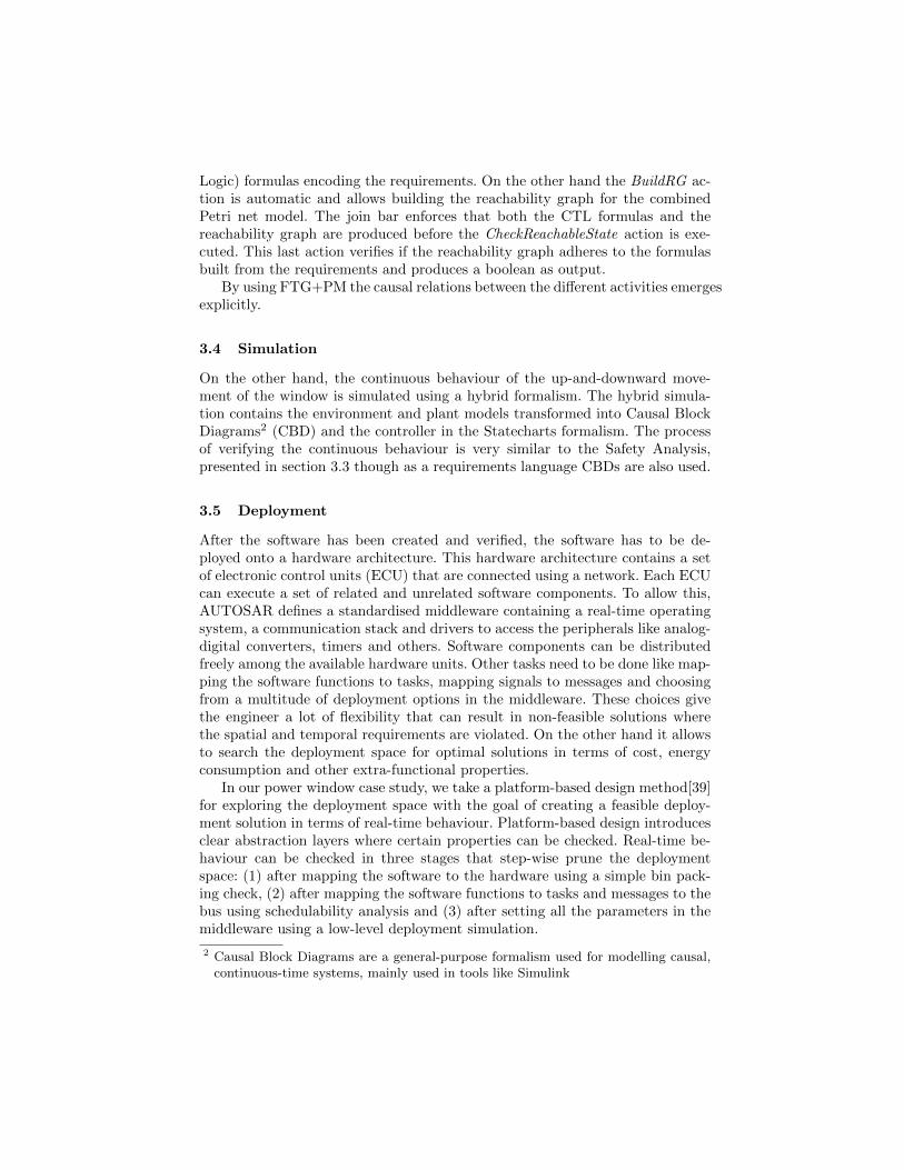
Logic) formulas encoding the requirements. On the other hand the BuildRG ac-tion is automatic and allows building the reachability graph for the combinedPetri net model. The join bar enforces that both the CTL formulas and thereachability graph are produced before the CheckReachableState action is exe-cuted. This last action verifies if the reachability graph adheres to the formulasbuilt from the requirements and produces a boolean as output.
By using FTG+PM the causal relations between the different activities emergesexplicitly.
3.4 Simulation
On the other hand, the continuous behaviour of the up-and-downward move-ment of the window is simulated using a hybrid formalism. The hybrid simula-tion contains the environment and plant models transformed into Causal BlockDiagrams2 (CBD) and the controller in the Statecharts formalism. The processof verifying the continuous behaviour is very similar to the Safety Analysis,presented in section 3.3 though as a requirements language CBDs are also used.
3.5 Deployment
After the software has been created and verified, the software has to be de-ployed onto a hardware architecture. This hardware architecture contains a setof electronic control units (ECU) that are connected using a network. Each ECUcan execute a set of related and unrelated software components. To allow this,AUTOSAR defines a standardised middleware containing a real-time operatingsystem, a communication stack and drivers to access the peripherals like analog-digital converters, timers and others. Software components can be distributedfreely among the available hardware units. Other tasks need to be done like map-ping the software functions to tasks, mapping signals to messages and choosingfrom a multitude of deployment options in the middleware. These choices givethe engineer a lot of flexibility that can result in non-feasible solutions wherethe spatial and temporal requirements are violated. On the other hand it allowsto search the deployment space for optimal solutions in terms of cost, energyconsumption and other extra-functional properties.
In our power window case study, we take a platform-based design method[39]for exploring the deployment space with the goal of creating a feasible deploy-ment solution in terms of real-time behaviour. Platform-based design introducesclear abstraction layers where certain properties can be checked. Real-time be-haviour can be checked in three stages that step-wise prune the deploymentspace: (1) after mapping the software to the hardware using a simple bin pack-ing check, (2) after mapping the software functions to tasks and messages to thebus using schedulability analysis and (3) after setting all the parameters in themiddleware using a low-level deployment simulation.
2 Causal Block Diagrams are a general-purpose formalism used for modelling causal,continuous-time systems, mainly used in tools like Simulink
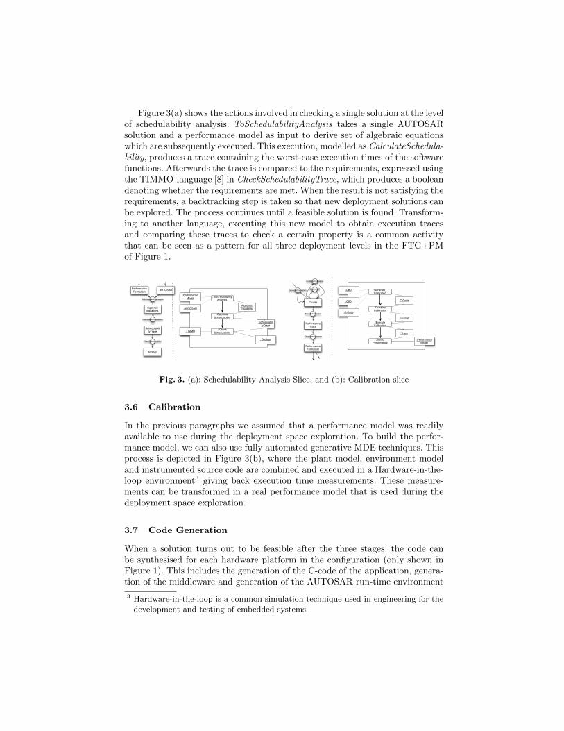
Figure 3(a) shows the actions involved in checking a single solution at the levelof schedulability analysis. ToSchedulabilityAnalysis takes a single AUTOSARsolution and a performance model as input to derive set of algebraic equationswhich are subsequently executed. This execution, modelled as CalculateSchedula-bility, produces a trace containing the worst-case execution times of the softwarefunctions. Afterwards the trace is compared to the requirements, expressed usingthe TIMMO-language [8] in CheckSchedulabilityTrace, which produces a booleandenoting whether the requirements are met. When the result is not satisfying therequirements, a backtracking step is taken so that new deployment solutions canbe explored. The process continues until a feasible solution is found. Transform-ing to another language, executing this new model to obtain execution tracesand comparing these traces to check a certain property is a common activitythat can be seen as a pattern for all three deployment levels in the FTG+PMof Figure 1.
:ToSchedulabilityAnalysis
: CheckSchedulability
:CalculateSchedulability
:Algebraic Equations
: Boolean
:SchedulabilityTrace
:TIMMO
:AUTOSAR
:PerformanceModel
AUTOSAR
Algebraic Equations
Performance Formalism
ToSchedulabilityAnalysis
SchedulabilityTrace
Boolean
CheckSchedulability
CalculateSchedulability
:Generate_Calibration
:ExecuteCalibration
:ExtractPerformance
:CombineCalibration
:Trace
:C-Code
:Performance Model
:C-Code
:C-Code
:CBD
:CBD
C-code
Performance Trace
ExecuteCalibration
Performance Formalism
ExtractPerformance
CcombineCGenerateCalibration
CombineCalibration
Fig. 3. (a): Schedulability Analysis Slice, and (b): Calibration slice
3.6 Calibration
In the previous paragraphs we assumed that a performance model was readilyavailable to use during the deployment space exploration. To build the perfor-mance model, we can also use fully automated generative MDE techniques. Thisprocess is depicted in Figure 3(b), where the plant model, environment modeland instrumented source code are combined and executed in a Hardware-in-the-loop environment3 giving back execution time measurements. These measure-ments can be transformed in a real performance model that is used during thedeployment space exploration.
3.7 Code Generation
When a solution turns out to be feasible after the three stages, the code canbe synthesised for each hardware platform in the configuration (only shown inFigure 1). This includes the generation of the C-code of the application, genera-tion of the middleware and generation of the AUTOSAR run-time environment
3 Hardware-in-the-loop is a common simulation technique used in engineering for thedevelopment and testing of embedded systems
(RTE) that is required to glue the application code and middleware code to-gether.
4 FTG+PM: Formal Definition
In the following definitions we will provide the precise abstract syntax of theFTG+PM formalism. We will mention the relation between FTG+PM abstractand concrete syntax (as can be observed e.g., in Figure 1) whenever the abstractsyntax definitions do not make that relation immediately obvious.
Definition 1. Language and ModelWe call the set of all languages Form and the set of all models Models. A
model always conforms4 to a given language, formally written model conformsTo f ,where f ∈ Form. The set of models that conform to a language f ∈ Form isthe set Modelsf =
{model ∈Models | model conformsTo form
}.
Definition 2. Transformation and Transformation ExecutionGiven a set of languages F ⊆ Form, we formally write ts1,...,smt1,...,tn to denote
a transformation t where {s1, . . . , sm} ∈ P(F ) is the set of source languagesof t and {t1, . . . , tn} ∈ P(F ) is the set of target languages of t. The set of alltransformations for a set of languages F ⊆ Form is written TrF .
Given a set of languages F ⊆ Form, a transformation execution of ts1,...,smt1,...,tn ∈TrF is a computation that: receives a set of inputs models im1, . . . , imm suchthat mik conformsTo sk (1 ≤ k ≤ m); produces a set of outputs modelsom1, . . . , omm such that omk conformsTo tk (1 ≤ k ≤ n). Given the above,we write ex executionOf t to denote ex is an execution of t. The set of allexecutions of t is written Exect.
Definition 3. Formalism Transformation Graph (FTG)A formalism transformation graph is a tuple 〈F , τ〉 ∈ Ftg, where F ⊆ Form
and τ ⊆ TrF .
In the FTG definition 3 the “graph” notion comes from the fact that lan-guages can be seen as nodes of a graph where transformations connect the nodesvia relations of input and output. In what follows we use the notation Vs todenote the set of variables over set s.
Definition 4. Process Model (PM)Let ftg = 〈F , τ〉 ∈ Ftg. A process model of ftg is a tuple 〈Act,Obj,CtrlNode,
CtrlF low,DataF low,Guard,CtrlNodeType〉 ∈ Pmftg, where:
– Act ⊆⋃
ex=Exect Vex such that t ∈ τ– Obj ⊆
⋃mod=Modelsf Vmod such that f ∈ F
– CtrlNode ⊆ NodeID, where NodeID is a set of control node identifiers;– CtrlF low ⊆ (Act×Act) ∪ (Act× CtrlNode) ∪ (CtrlNode×Act)
4 this is the typical conformance relation as found in the literature [23]
– DataF low ⊆ (Act×Obj) ∪ (Obj ×Act) ∪ (Act×Node)– Guard : CtrlF low ↪→ conditionsOver(F )5
– CtrlNodeType : CtrlNode→{forkJoin, decision, begin, end
}with the following additional constraints:
– for all a ∈ Act inbound dataflow arrows carry the transformation’s inputmodels; outbound dataflow arrows carry the transformation’s output models;
– for all pm ∈ Pmftg, CtrlNodeType is surjective regarding the restriction ofthe function’s co-domain to
{begin, end
}, meaning that for a given process
model only one start and only one end control node exist;– if (a,n), (a′,n′) ∈ CtrlF low then a = a′, meaning only one control flow arc
is allowed from each activity;– if (a, d), (a′, d′) ∈ DataF low then a = a′, meaning only one data flow arc is
allowed from each activity;– if (d,n) ∈ DataF low then CtrlNodeType(n) = decision;– Guard
((n,n′)
), where (n,n′) ∈ CtrlF low, is defined if and only if
CtrlNodeType(n) = decision.
The abstract syntax of PM in definition 4 includes the fundamental set ofconstructs in Activity Diagrams, as well as data flow: Act are action nodes (in ourcase placeholders for executions of transformations) and are represented as roundedged rectangles; Obj are object nodes (in our case placeholders for instances oflanguages) and are represented by square edged rectangles. CtrlNode is a setof control nodes typed by the CtrlNodeType function and having the respec-tive classical activity diagram concrete syntax. The CtrlF low and DataF lowrelations specify the edges between action, object and control nodes. Finallythe Guard function allows defining guards for edges which are outbound of de-cision nodes. The constraints following the first part of definition 4 insure thewell-formedness of the PM Activity Diagrams.
Definition 5. FTG+PMA FTG+PM is a pair 〈ftg, pm〉 ∈ FtgPm, where ftg = 〈F , τ〉 ∈ Ftg and
pm ∈ Pmftg is a process model of ftg.
The semantics of a 〈ftg, pm〉 ∈ FtgPm is a set of traces associated withexecutions of the activity diagram specified in pm. The semantics of ActivityDiagrams with data flow have been addressed by Storrle in [41] and are builtby transforming UML 2.0 Activity Diagrams into Coloured Petri Nets [1], assuggested by the UML 2.0 specification [35]. The resulting traces are labelledtransition systems where states hold the models available at each given momentof the development process and transitions represent transformation executions.Notice that in definition 4 action nodes and object nodes are defined as variablesof transformation executions and instances of languages, respectively. However,when the traces are calculated the PM’s variables are replaced by concrete trans-formation executions and models (see definition 2).
5 we use ↪→ to denote a partial functions.
5 Discussion
The contribution of the paper is a framework for formalism transformation,consisting of the Formalism Transformation Graph and the Process Model. Itsusefulness was illustrated by a small case study from the automotive domain.The framework allows the MDE process to be flexible. Also, insight in the domaincan be gained as the FTG+PM provides modellers with a means to describe andeven prescribe the MDE process. We suggest that FTG+PMs should be devisedfor each specific domain where MDE is used. Thus, PMs model domain-specificMDE practices. As the FTG charts all different formalisms used as well as theirrelationships, it can be seen as a model of all MDE artefacts.
The languages for both FTGs and PMs, as well as their relationships, wereformalised in Section 4. In practice, we use a subset of UML Activity Diagrams2.0 to express PMs. The metamodel of FTGs is a bipartite graph. Its metamodelis straightforward and was not shown in this paper because of spatial constraints.The explicit modelling of the FTG+PM and its execution semantics allow us toextend the formalisms in an MDE fashion, reaping all its benefits.
In its current state, the FTG+PM can be improved in several ways to makeit more valuable. (1) The execution semantics of the PM could include an anno-tation mechanism to keep some information on an artifact such as author, datecreated, tool used, and formalism it conforms to (similar to [6]); (2) A differencecan be made in the FTG between general-purpose formalisms, transformationsthat are likely to be reused (e.g., Petri-net to reachability graph) and domain-specific parts that are only relevant to one particular PM (e.g., C-code calibrationfor Autosar C-code). The general-purpose artifacts can be browsed as a libraryof off-the-shelf formalisms and transformations when creating a new PM; (3)Currently, all relationships in the FTG are transformations. We can classify thetransformations according to their type and/or intention, e.g., model-to-modeltranslation, verification, refinement, abstraction, code generation, simulation,etc. [25]. Generalising this further, we can add pre- and post conditions as prop-erties to the transformations in the FTG. During the execution of the PM, thesepre- and post conditions can be checked to ensure validity and correctness ofthe transformations. Moreover, this strategy can be combined with analyticaltechniques to prove properties of some of the general purpose transformationsthat are re-used widely.
Using the FTG+PM approach results in an ever growing centralised FTG,and an ever growing collection of PMs which can be used for empirical evaluationof current MDE techniques. We anticipate that by using data mining techniqueson a collection of FTG+PMs, patterns will become apparent that can enablereuse and help designers to solve problems of ever increasing complexity. TheFTG+PM framework can also be used as an enabler for tool integration wherethe transformations between the different model representations in the FTG canbe looked up and reused within the PMs.
6 Related Work
Our work is focused on creating a platform for unifying MDE practices by defin-ing a detailed and precise model, namely the FTG+PM, to guide the modeltransformation process. While FTG+PM is generic and can be applied in the de-velopment of systems in various domains, we have worked on a case study in theautomotive domain to illustrate our FTG+PM and its applicability. There havebeen research carried out in both academia and industry on the model-driven en-gineering of automotive cyberphysical systems [16, 46, 37, 15]. [7] present a MDEframework based on SysWeaver for the development of AUTOSAR-compliantautomotive systems.
Research related to our approach can be divided into two parts: modellingthe relations between models explicitly (similar to the FTG), and describing thetransformations explicitly as an MDD process (similar to the PM).
6.1 Inter-model modelling
The idea of modelling the existing relations between different processes was firstintroduced by Vangheluwe et al. [44] in the context of simulation. A Formal-ism Transformation Lattice, addressing the same goals the Formalism Trans-formation Graph, is introduced in [45]. The idea is further elaborated in [10],advocating AToM3 [11] as a suitable tool for its implementation. Indeed, we useAToM3 and its successor AToMPM excessively in the power window case study.The FTG of [10] has no formal character however and leaves transformationsimplicit.
Bezivin et al. introduce the concept of megamodels [6] as a global view of theconsidered artifacts in a system. They claim that this concept is essential in anyMDD platform. Key in their approach is that not only models, but also tools andthe services and operations they provide are also represented as models, with allsorts of relations in between. Megamodelling is also called modelling in the large.A megamodel is mainly presented as a means to store metadata (e.g., that anartifact was generated by a particular transformation or created in a particulartool, what its metamodel is, etc.). The authors state that process modelling couldbe achieved with megamodelling. [14] continues on megamodelling, and four dif-ferent kinds of relations are presented, referring to the semantics: DecomposedIn,RepresentationOf, ElementOf, and ConformsTo.
Salay et al. introduce macromodels as a means to capture the intended pur-pose and a set of intended relationships (such as refinement, instantiations, refac-torings, etc.) of models [38]. They model relationships between formalisms in asimilar way as in megamodeling, but they allow modelling these relationshipsexplicity as metamodels. Their goal is to improve understandability, to enforcecontraints on models even before they are created, to check for consistency be-tween models and to manage evolution of the modeling project. Similarly tomegamodeling, there is no support for workflow modeling.
6.2 The MDD process
Various model transformation languages and toolsets are used in practice today,such as the OMG-standard QVT [26], Atlas Transformation Language [22], andAToM3 [11]. Such tools are used independently for carrying out some particularpurpose within MDE. However, research has shown a need for unifying MDEpractices and tools [5] [31].
Process modelling has a huge following in research, resulting in many mod-elling languages. Recent years, most of these languages are based on π-calculusand/or Petri nets. π-calculus [29] was introduced by Robert Milner, and is basedon Calculus of Communicating Systems (CCS) [28] which was developed by Mil-ner in Parallel with Hoare’s Communicating Sequential Processes (CSP) [19], allof which are prominent process calculi. Petri nets [36] were created by CarlAdam Petri as a graphical formalism to express concurrent systems. Examplesof used process modelling languages that have roots in π-calculus and/or Petrinets are Business Process Model and Notation (BPMN) [34], the textual Busi-ness Process Execution Language (BPEL) [32], Coloured Petri nets [21] in e.g.,CPNTools [20], Yet Another Workflow Language (YAWL) [43], Event-DrivenProcess Chains (EPC’s) [42] and UML Activity Diagrams [35]. The XML Pro-cess Definition Language (XPDL) [47] is a well-known standard defined by theWorkflow Management Coalition (WfMC) for storing visual diagrams, such asBPMN diagrams.
OMG’s Software Process Engineering Metamodel (SPEM) [3], formerly knownas Unified Process Model (UPM), is designed for defining the process of usingdifferent UML models in a project. SPEM is defined as a generic software processlanguage, with generic work items having different roles. It is merely a genericframework for expressing processes, and does not include e.g., a visual concretesyntax.
Oldevik et al. [33] present a metamodel-based UML profile for model transfor-mation and code generation. The goal of the work is provide a framework thatassists transformations in the MDE lifecycle by defining activities and tasks.The paper outlines the semantics of the transformations required to map mod-els models at a high level of abstraction (e.g. requirements) to models at thearchitecture and platform-specific levels.
Similar to our Process Models, Van Gorp et al. employ Activity Diagrams 1.0to express chains of transformations [18]. Their main goals are understandabilityand reusability. Their notation uses regular States to denote types of models, andObject Flow States to denote transformations. The rather preliminary languageuses Synchronisation Bars as well. They are used to denote synchronous execu-tion (in case of multiple outputs of Synchronisation Bars), as well as multipletransformation inputs/outputs for a transformation (in case of multiple inputsof Synchronisation Bars). The language does not include decision diamonds andhas no precise semantics, but is rather used as a documentation means.
We ultimately chose Activity Diagrams 2.0 as our formalism for modellingprocesses for three reasons: the formalism is well-known, especially in the field
of modelling, the formalism is well-supported by general tools, and it allows usto model both control flow and data flow.
7 Conclusion
In this paper, we presented a framework for carrying out formalism transforma-tions within MDE. We proposed the Formalism Transformation Graph (FTG)and the Process Model (PM) to guide the model-driven development process.We introduced the FTG+PM framework, composed of the FTG and its com-plement, the PM. The FTG comprises formalisms as nodes and transformationsas edges, and shows the different languages that need to be used at each stageof development. Meta-modelling and model transformation are the basis of theFTG. The FTG explicitly models the relations between requirements, design,simulation, verification, and deployment languages. The transformations are de-picted as Activity Diagram 2.0 actions, and the control flow and the data flowbetween each transformation action are detailed in the Process Model (PM).
We have applied FTG+PM on a non-trivial case study of the design of anautomotive power window controller. We have constructed the FTG and PM forthe target domain in the FTG+PM language. Following requirements elicitationand specification using the SysML use case diagram and requirements diagramformalisms, we have defined domain specific languages that allow modelling ofthe main components of the control system: the environment, the plant, andthe control. The DSLs are transformed to Petri nets to carry out reachabilityanalysis on the one hand, and to a hybrid simulation formalism (composed of acontinuous time formalism Causal Block Diagrams, and a discrete-event formal-ism, Statecharts) to ensure that system constraints are satisfied. After successfulsafety analysis and simulation, the control model in the Statecharts formalismis mapped on to deployment models. We have used the AUTOSAR middle-ware to deploy our software onto a hardware architecture. The deployment is amultiphase process beginning with the generation of a calibration infrastructurewhich feeds into a performance model, followed by an intial architecture deploy-ment (in C-code), bin packing analysis and schedulability analysis to check thatperformance constraints are being met, and finally simulation using the DEVSformalism. Additionally, timing requirements (represented using the TIMMOlanguage) are derived from the inital requirements diagrams, and integrated andchecked during deployment. Once the simulation outputs an acceptable trace,the deployment models are transformed to middleware code and RTE code.
The FTG and PM we have introduced can be adapted for use in variousdomains. It provides a complete model-driven process that is based on meta-modelling, multi-abstraction and multi-formalism modelling, and model trans-formation. We plan on extending this work and adapting the FTG+PM forfeature-oriented software development of (software) product lines.
References
1. Coloured Petri Nets: Basic Concepts, Analysis Methods and Practical Use (Volume1), volume 1 of EATCS Series. Springer Verlag, 2003.
2. ATLAS transformation language, 2008. http://www.eclipse.org/m2m/atl/.3. SPEM version 2.0, OMG document number formal/2008-04-0, april 2008.4. AUTOSAR. Official webpage. http://www.autosar.org, 2010.5. Jean Bezivin and Erwan Breton. Applying the basic principles of model engi-
neering to the field of process engineering. UPGRADE: European Journal for theInformatics Professional, 27-33, 2004.
6. Jean Bezivin, Frederic Jouault, and Patrick Valduriez. On the need for megamod-els. In Proceedings of the OOPSLA/GPCE, 2004.
7. G. Bhatia, K. Lakshmanan, and R. Rajkumar. An End-to-End Integration Frame-work for Automotive Cyber-Physical Systems Using SysWeaver. In AVICPS 2010,pages 23–30, 2010.
8. H. Blom, R. Johansson, and H. Lonn. Annotation with Timing Constraints inthe Context of EAST-ADL2 and AUTOSAR, the Timing Augmented DescriptionLanguage. In STANDRTS’09, 2009.
9. Steve Cook, Gareth Jones, Stuart Kent, and Alan Cameron Wils. Domain-SpecificDevelopment with Visual Studio DSL Tools. Addison-Wesley Professional, 2007.
10. J. de Lara, H. Vangheluwe, and M. Alfonseca. Meta-modelling and graph grammars
for multi-paradigm modelling in AToM3. Soft. and Sys. Mod., 3(3):194–209, 2004.11. Juan de Lara and Hans Vangheluwe. AToM3: A Tool for Multi-formalism and
Meta-Modelling. In FASE ’02, pages 174–188. Springer-Verlag, 2002.12. Richard C. Dorf. Modern Control Systems. Addison-Wesley Longman Publishing
Co., Inc., Boston, MA, USA, 12th edition, 2011.13. Gregoire Dupe, Mariano Belaunde, Romain Perruchon, Helena Besnard, Florian
Guillard, and Vivian Oliveres. SmartQVT. http://smartqvt.elibel.tm.fr/.14. Jean-Marie Favre. Megamodelling and etymology. In Transformation Techniques
in Software Engineering, Dagstuhl Seminar Proceedings, 2006.15. J. Friedman and J. Ghidella. Using model-based design for automotive systems
engineering - requirements analysis of the power window example. SAE, 2006.16. Z. Gao, H. Xia, and G. Dai. A model-based software development method for
automotive cyber-physical systems. Comput. Sci. Inf. Syst, 8(4):1277–1301, 2011.17. H. Giese, T. Levendovszky, and H. Vangheluwe. Summary of workshop on multi-
paradigm modeling: concepts and tools. In MoDELS’06, pages 252–262, 2006.18. P. Van Gorp, D. Janssens, and T. Gardner. Write once, deploy n: A performance
oriented mda case study. In EDOC, pages 123–134. IEEE Computer Society, 2004.19. C. A. R. Hoare. Communicating sequential processes. Prentice-Hall, Inc., Upper
Saddle River, NJ, USA, 1985.20. K. Jensen, L. Kristensen, and L. Wells. Coloured Petri Nets and CPN Tools
for modelling and validation of concurrent systems. Int. J. Softw. Tools Technol.Transf., 9(3):213–254, 2007.
21. Kurt Jensen. Coloured Petri nets (2nd ed.): basic concepts, analysis methods andpractical use: volume 1. Springer-Verlag, London, UK, 1996.
22. F. Jouault, F. Allilaire, J. Bezivin, and I. Kurtev. ATL: A model transformationtool. Science of Computer Programming, 72(1-2):31 – 39, 2008.
23. Thomas Kuhne. Matters of (meta-)modeling. Software and System Modeling,5(4):369–385, 2006.
24. L. Lucio, J. Denil, and H. Vangheluwe. An overview of model transformations fora simple automotive power window. Technical report, McGill University, 2012.
25. T. Mens and P. Van Gorp. A taxonomy of model transformation. Electron. NotesTheor. Comput. Sci., 152:125–142, March 2006.
26. Meta object facility (MOF) 2.0 query/view/transformation (QVT), OMG docu-ment number formal/2011-01-01, available from www.omg.org, 2011. Version 1.1.
27. Metacase. Domain-Specific Modeling with MetaEdit+: 10 times faster than UML,2009.
28. R. Milner. A Calculus of Communicating Systems. Springer-Verlag New York,Inc., Secaucus, NJ, USA, 1982.
29. R. Milner. Communicating and mobile systems: the pi-calculus. Cambridge Uni-versity Press, New York, NY, USA, 1999.
30. W. Moore, D. Dean, A. Gerber, G. Wagenknecht, and P. Vanderheyden. EclipseDevelopment using the GEF and the EMF. IBM RedBooks, February 2004.
31. Pieter J. Mosterman and Hans Vangheluwe. Computer Automated Multi-ParadigmModeling: An Introduction. Simulation, 80(9):433–450, 2004.
32. OASIS. Web Services Business Process Execution Language Version 2.0, Apr. 2007.33. J. Oldevik, A. Solberg, B. Elvesæter, and A. Berre. Framework for Model Trans-
formation and Code Generation. In EDOC, pages 181–189, 2002.34. OMG. Business Process Model and Notation Version 2.0, Jan. 2011.35. OMG. Unified Modeling Language (UML) 2.4.1 Superstructure, Aug. 2011.36. J. Peterson. Petri nets. ACM Comput. Surv., 9(3):223–252, September 1977.37. S. Prabhu and P. Mosterman. Model-based design of a power window system:
Modeling, simulation and validation. In IMAC-XXII, 2004.38. R. Salay, J. Mylopoulos, and S. Easterbrook. Managing models through macro-
modeling. In ASE, pages 447–450. IEEE, 2008.39. A. Sangiovanni-Vincentelli and G. Martin. Platform-based design and software
design methodology for embedded systems. IEEE Des. Test, 18(6):23–33, 2001.40. S. Sendall and W. Kozaczynski. Model transformation: The heart and soul of
model-driven software development. IEEE Software, 20:42–45, September 2003.41. H. Storrle. Semantics and Verification of Data Flow in UML 2.0 Activities. In
ENTCS, pages 35–52. Elsevier, 2004.42. W.M.P. van der Aalst. Formalization and verification of event-driven process
chains. Information and Software Technology, 41(10):639 – 650, 1999.43. W.M.P. van der Aalst and A.H.M. ter Hofstede. YAWL: yet another workflow
language. Information Systems, 30(4):245 – 275, 2005.44. Hans Vangheluwe, Bo Hu Li, Y. V. Reddy, and G. C. Vansteenkiste. A framework
for concurrent simulation engineering. In Simulation in Concurrent Engineering,pages 50–55. SCS, 1993.
45. Hans Vangheluwe and G. C. Vansteenkiste. A multi-paradigm modeling and sim-ulation methodology : formalisms and languages. In ESS’96, pages 168–172, 1996.
46. S. Wang. Model transformation for high-integrity software development in deriva-tive vehicle control system design. In HASE, pages 227–234, 2007.
47. WfMC. XML process definition language (XPDL), October 2005.