Embed Size (px)
Citation preview

Publications No.
INSTALLATIONINSTRUCTIONS
Accessory Application
© 2014 American Honda Motor Co., Inc. – All Rights Re
VERSION 1
www.collegehillshonda.com
TRAILER HITCHserved. AII 52395 (140
2015 CR-V
9) 08L9
Issue Date
SEP 2014
PARTS LIST
Trailer Hitch KitP/N 08L92-T0A-100
Trailer hitch
Ball mount
6 Hex bolts, 10 x 40 mm
6 Spring washers, 10 mm
6 Plain washers, 10 mm
Hex bolt, 12 x 50 mm
Spring washer, 12 mm
2 Plain washers, 12 mm
Hex nut, 12 mm
Hitch pin
Hitch pin clip
Receiver cover
Center plate
Trailer Hitch Harness KitP/N 08L91-T0A-100
Control unit bracket
Control unit harness
Socket harness
1 of 212-T0A-1000-90

www.collegehillshonda.com
Control unit
Fuse label
7.5A Fuse
2 Wire ties with clip
7 Wire ties
4 Aluminium tapes
Connector clip
2 of 21 AII 52395
Drain Clip
2 Hex bolts, 6 x 40 mm
3 Flange nuts, 6 mm
Pillar clip
Accessory User’s Information Manual
(1409) © 2014 American Honda Motor Co., Inc. – All Rights Reserved.

www.collegehillshonda.com
TOOLS AND SUPPLIES REQUIREDPhillips screwdriverSmall flat-tip screwdriver10 mm Open end wrench10 mm, 14 mm, 17 mm, and 19 mm SocketsPushpinRatchet3 mm and 6 mm Drill bitsEye protection (face shield, safety goggles, etc.)FileBlanketIsopropyl alcoholShop towel20 mm Hole sawDrillTapeHex wrenchDiagonal cuttersFelt-tip penUtility knifeRubber malletTorque wrenchRulerThe following tools are available through the Honda Tool and Equipment program. On the iN, click on: Service > Service Bay > Tool and Equipment Program, then enter the number under “Search.” Or call 888-424-6857.
• Air Saw (Snap-on AT192A)• Trim Tool Set (T/N: SOJATP2014)
© 2014 American Honda Motor Co., Inc. – All Rights Reserved. AII 5239
Illustration of the Trailer Hitch on the Vehicle
QA11801AX
CONTROL UNIT HARNESS
SOCKET HARNESS
TRAILER HITCH
CONTROL UNIT
5A FUSE
INSTALLATION
Customer Information: The information in this installation instruction is intended for use only by skilled technicians who have the proper tools, equipment, and training to correctly and safely add equipment to your vehicle. These procedures should not be attempted by “do-it-yourselfers.”
1. Disconnect the negative cable from the battery.2. Remove the driver’s dashboard under cover.
Q0N2021AGPINDRIVER’S DASHBOARD UNDER COVER
KNOBTurn.
CLIP
5 (1409) 3 of 21

www.collegehillshonda.com
3. If equipped, remove the tonneau cover.Q0D0101AE
TONNEAU COVER
TONNEAU COVER HOLDER
SPRING-LOADED END
VEHICLE PANEL
4. Pull the lever, and fold down the left rear seat.
Q0D0102AE
LEVERPull.
LEFT REAR SEATFold down.
4 of 21 AII 52395
5. Lift the left rear seat back.
QA53101AB
FRONT
LEFT REAR SEAT BACKLift.
6. Remove the left rear door sill trim.
Q0D0103AE
HOOK
3 CLIPS
FRONT
5 RETAINING TABS
LEFT REAR DOOR SILL TRIM
7. Pull the lever, and fold down the left rear seat back.
(1409) © 2014 American Honda Motor Co., Inc. – All Rights Reserved.

www.collegehillshonda.com
8. Remove the cargo floor board.Q0D0104AE2 HOOKS
CARGO FLOOR BOARD
9. Pull away the weatherstrip, and remove the rear trim panel.
Q0D0105BE
4 CLIPS2 CLIPS
2 HOOKS
WEATHERSTRIPPull away.
REAR TRIM PANEL
FRONT
2 RETAINING TABS
© 2014 American Honda Motor Co., Inc. – All Rights Reserved. AII 523
10. Remove the left rear damper cover by lifting up.
Q0D0106AE
FRONT
LEFT REAR SIDE TRIM PANEL
7 RETAINING TABS
4 HOOKS
LEFT REAR DAMPER COVER
11. Release the floor carpet from the left floor carpet cover.
QA53102AB
FRONT
FLOOR CARPET
3 CLIPS
LEFT REAR SIDE TRIM PANEL
LEFT FLOOR CARPET COVER
95 (1409) 5 of 21
www.collegehillshonda.com
12. Remove the left floor carpet cover.Q0D0107AE
LEFT FLOOR CARPET COVER
FRONT 2 RETAINING TABS
3 CLIPS
LEFT REAR SIDE TRIM PANEL
LEFT REAR SEAT
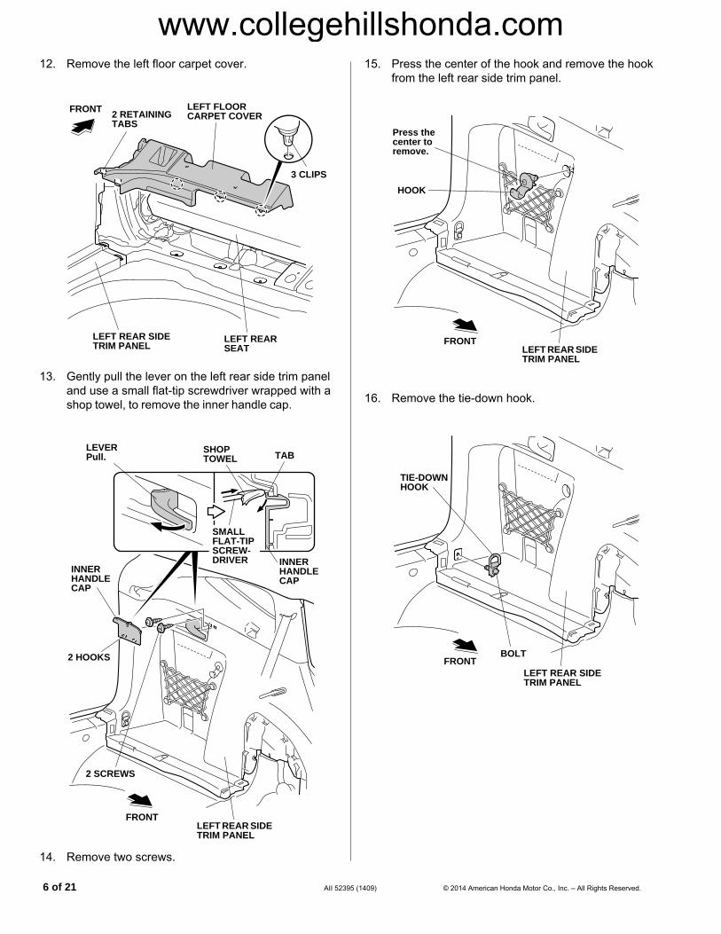
13. Gently pull the lever on the left rear side trim panel and use a small flat-tip screwdriver wrapped with a shop towel, to remove the inner handle cap.
Q0D0108AEFRONT
LEFT REAR SIDE TRIM PANEL
INNER HANDLE CAP
2 HOOKS
2 SCREWS
SMALL FLAT-TIP SCREW-DRIVER INNER
HANDLE CAP
TABSHOP TOWEL
LEVERPull.
14. Remove two screws.
6 of 21 AII 52395
15. Press the center of the hook and remove the hook from the left rear side trim panel.
Q0D0109AEFRONT
HOOK
LEFT REAR SIDE TRIM PANEL
Press the center to remove.
16. Remove the tie-down hook.
Q0D0110AEFRONT
BOLT
LEFT REAR SIDE TRIM PANEL
TIE-DOWN HOOK
(1409) © 2014 American Honda Motor Co., Inc. – All Rights Reserved.
www.collegehillshonda.com
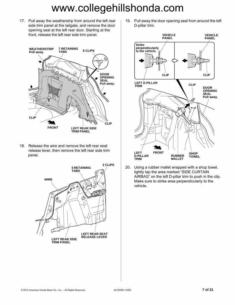
17. Pull away the weatherstrip from around the left rearside trim panel at the tailgate, and remove the door opening seal at the left rear door. Starting at the front, release the left rear side trim panel.
Q0N2907BEFRONT
6 CLIPS
CLIP
LEFT REAR SIDE TRIM PANEL
DOOR OPENING SEALPull away.
7 RETAINING TABS
WEATHERSTRIPPull away.
CLIP
18. Release the wire and remove the left rear seat release lever, then remove the left rear side trim
panel.
QA72305AG
2 CLIPS5 RETAINING TABS
LEFT REAR SIDE TRIM PANEL
LEFT REAR SEAT RELEASE LEVER
WIRE
© 2014 American Honda Motor Co., Inc. – All Rights Reserved. AII 5239
19. Pull away the door opening seal from around the left D-pillar trim.
Q0N2909AE
VEHICLE PANEL
LEFT D-PILLAR TRIM
CLIP
VEHICLE PANEL
Strike perpendicularly to the vehicle.
CLIP
CLIPDOOR OPENING SEALPull away.
SHOP TOWELRUBBER
MALLET
FRONTLEFT D-PILLAR TRIM
20. Using a rubber mallet wrapped with a shop towel, lightly tap the area marked “SIDE CURTAIN AIRBAG” on the left D-pillar trim to push in the clip. Make sure to strike area perpendicularly to the vehicle.
5 (1409) 7 of 21

www.collegehillshonda.com
21. Remove the left D-pillar trim.Q0N2910AE
10 CLIPSWEATHERSTRIPPull away.
FRONT
LEFT D-PILLAR TRIM
22. Open the right rear door.
Q0D2001AG
CLIP
RIGHT REAR WHEEL ARCH PROTECTOR
2 SCREWS
23. Remove the one clip and the two screws from the right rear wheel arch protector. If equipped, remove the splash guards.
8 of 21 AII 52395
24. Remove the right rear wheel arch protector.
Q0D2002BG5 CLIPS
6 CLIPS
RIGHT REAR WHEEL ARCH PROTECTOR
RETAINING TAB
RIGHT REAR FENDER
RETAINING TAB
25. Remove the left rear wheel arch protector the same way.
26. On each side of the vehicle, apply masking tape to the rear bumper, right taillight and right rear fender as shown.
Q0D0112AE
REAR BUMPER
RIGHT TAILLIGHT
RIGHT REAR FENDER
MASKING TAPE
(1409) © 2014 American Honda Motor Co., Inc. – All Rights Reserved.

www.collegehillshonda.com
27. Remove the rear bumper.• Remove the two covers, two bumper screws, two bolts, two screws, and five clips.
Q0D0201BE
2 COVERS
REAR BUMPER 2 BOLTS
5 CLIPS
2 BUMPER SCREWS
2 SCREWS
• On each side, release five retaining tabs along the fenderwell.
Q0D0202AEREAR BUMPER
RIGHT REAR FENDER
5 RETAINING TABS
© 2013 American Honda Motor Co., Inc. – All Rights Reserved. AII 52395
• On each side, release four retaining tabs.
Q0D0203AEREAR BUMPER
RIGHT TAILLIGHT
4 RETAINING TABS
• With the help of an assistant, remove the rear bumper.
• Place the rear bumper on a blanket after removal.
Q0D0204AEREAR BUMPER
(1409) 9 of 21

www.collegehillshonda.com
28. Remove the rear under cover.QA11802AX
FRONT
3 BOLTSREAR UNDER COVER
29. Remove the two muffler bushings from the vehicle pins. NOTE: Be careful not to damage the muffler.
QA22501AX
FRONT
MUFFLER
BUSHING
BUSHING
PIN
10 of 21 AII 52395
Installing the Trailer Hitch
30. Loosely install the trailer hitch on the vehicle frame with six 10 mm plain washers, six 10 mm spring washers, and six 10 x 40 mm hex bolts.
QA11803BX
FRONT
6 HEX BOLTS, 10 x 40 mmLoosely install.
6 PLAIN WASHERS, 10 mm
TRAILER HITCH
VEHICLE FRAME
6 SPRING WASHERS, 10 mm
31. Loosely install the center plate to the trailer hitch with two 12 mm plain washers, one 12 mm spring washer, one 12 mm hex nut, and one 12 x 50 mm hex bolt through the tow hook.
QA11901CX
PLAIN WASHER, 12 mm
CENTER PLATE
SPRING WASHER, 12 mm
FRONT
TRAILER HITCH
HEX BOLT, 12 x 50 mmLoosely install.
HEX NUT, 12 mm
TOW HOOK
PLAIN WASHER, 12 mm
(1409) © 2014 American Honda Motor Co., Inc. – All Rights Reserved.

www.collegehillshonda.com
32. Tighten the bolts to the specified torque in the orderof and . Torque the 10 x 40 mm hex bolts to 46 N·m (34 lbf·ft). Torque the 12 x 50 mm hex bolt to 79 N·m (58 lbf·ft).
QA11902BX
FRONT
HEX BOLT, 12 x 50 mm79 N·m (58 lbf·ft)
6 HEX BOLTS, 10 x 40 mm46 N·m (34 lbf·ft)
2
1
33. Reconnect the muffler bushings to the vehicle pins.
© 2013 American Honda Motor Co., Inc. – All Rights Reserved. AII 52395
34. Using a felt-tip pen, mark the rear under cover at the measurements shown.
QA11903BX
FELT-TIP PEN
REAR UNDER COVER
REAR UNDER COVER
CURVE END
12 mm (0.5 in.)
RIB
FRONT VIEW
5 mm (0.2 in.)
R10
R10
5 mm (0.2 in.)
RIB
14 mm (0.6 in.)
30 mm (1.2 in.)
35. Using a pushpin, pierce the center of each mark made in step 34 on the rear under cover.
QA01017AB
20 mm HOLE SAW
PUSHPIN
MARKS
3 mm DRILL BIT
REAR UNDER COVER
DRILL
36. While wearing eye protection, drill each pierced mark on the rear under cover. First drill with a 3 mm drill bit, then enlarge each hole to 20 mm using a 20 mm hole saw.
(1409) 11 of 21

www.collegehillshonda.com
37. While wearing eye protection, use an air saw to cutthe rear under cover at the mark made in step 34. Remove any burrs and sharp edges from the corners.
QA11904BX
AIR SAW
Cut off.
Mark made in step 34.
REAR UNDER COVER
38. Using a felt-tip pen, mark the rear under cover at the measurements shown.
QA11905BX
FELT-TIP PEN
REAR UNDER COVER
CURVE END
25 mm (1.0 in)
RIB
FRONT VIEW
20 mm (0.8 in)
RIB
12 of 21 AII 52395
39. Using an air saw, cut the rear under cover at the mark made in step 38. Remove any burrs and sharp edges from the corners.
QA11906AX
AIR SAW
Cut off.
Mark made in step 38.
REAR UNDER COVER
(1409) © 2013 American Honda Motor Co., Inc. – All Rights Reserved.

www.collegehillshonda.com
40. Using an air saw, cut the rear under cover along thescribe line as shown. Remove any burrs and sharp edges from the corners. NOTE: Some rear under covers may not have the scribe line. If not, use the measurements shown.
200 mm 120 mm
120 mm200 mm
AIR SAW
Cut off.
REAR UNDER COVER
REAR UNDER COVER
SCRIBE LINE
© 2014 American Honda Motor Co., Inc. – All Rights Reserved. AII 5239
Routing the Socket Harness
41. Secure the socket harness to the trailer hitch with two 6 x 40 mm flange bolts and two 6 mm flange nuts.
QA11908AX
2 FLANGE BOLTS, 6 x 40 mm
2 FLANGE NUTS, 6 mm
SOCKET HARNESS
TRAILER HITCH
TRAILER HITCH
42. Route the socket harness along the rear bumper as shown.
QA11909AX
WIRE TIE
BUMPER BEAM
GREEN TAPE
VEHICLE PANEL
2 WIRE TIES WITH CLIP
SOCKET HARNESS
TRAILER HITCH
SOCKET HARNESS
GREEN TAPE
43. At the first green tape, secure the socket harness to the trailer hitch with one wire tie. At the next two green tapes, secure the socket harness to the vehicle panel with two wire ties with clip.
5 (1409) 13 of 21

www.collegehillshonda.com
44. Route the socket harness as shown, and secure it tothe hole in the bumper beam with one wire tie.
QA11910AX
WIRE TIE
BUMPER BEAM
Clean with isopropyl alcohol.
Align.
SOCKET HARNESS
ALUMINUM TAPE
VEHICLE PANEL
45. Using isopropyl alcohol on a shop towel, thoroughly clean the area where the aluminium tape will attach. Secure the socket harness to the vehicle panel with one aluminum tape.
46. Remove the forward vehicle grommet from the vehicle panel, and route the socket harness through the hole. Seat the grommet on the socket harness to the vehicle panel hole. NOTE: Do not pull on the socket harness when installing the grommet.
QA12001AX
GROMMET
OUTSIDE INSIDE
HOLE
VEHICLE GROMMETDiscard.
SOCKET HARNESS
VEHICLE PANEL
GROMMET
14 of 21 AII 52395
47. Using isopropyl alcohol on a shop towel, thoroughly clean the area where the aluminium tape will attach. Secure the socket harness to the vehicle panel with one additional aluminum tape.
QA12002AXClean with isopropyl alcohol.
SOCKET HARNESS
ALUMINUM TAPE
SOCKET HARNESS
VEHICLE PANEL
48. Inside the vehicle, secure the socket harness. 2WD vehicle: Route the socket harness as shown, and secure it to the vehicle panel with one wire tie.
QA12003BX
WIRE TIE
SOCKET HARNESS
FRONTVEHICLE PANEL
(1409) © 2014 American Honda Motor Co., Inc. – All Rights Reserved.

www.collegehillshonda.com
4WD vehicle: Route the socket harness along the vehicle harness and secure it to the vehicle harness with one wire tie.QA12004AX
WIRE TIE
VEHICLE HARNESS
SOCKET HARNESS
FRONT
Installing the Control Unit
49. Install the control unit bracket to the control unit.
QA12005AX
CONTROL UNIT BRACKET
CONTROL UNIT
© 2014 American Honda Motor Co., Inc. – All Rights Reserved. AII 5239
50. If the vehicle is equipped with a moonroof, install the drain clip to the control unit bracket.
QA12006AX
CONTROL UNIT BRACKET
DRAIN CLIP
51. Install the control unit bracket to the vehicle panel with one 6 mm flange nut.
QA12007AX
FRONT
VEHICLE PANEL
6 mm FLANGE NUT
CONTROL UNIT BRACKET
CONTROL UNIT BRACKET
VEHICLE PANEL
5 (1409) 15 of 21

www.collegehillshonda.com
If the vehicle is equipped with a moonroof, continue with step 52. Otherwise, go to step 55.52. Release the drain tube.
QA12008BX
FRONT
VEHICLE CLIP Slide.
CONTROL UNIT BRACKET VEHICLE
PANEL
DRAIN CLIP
DRAIN TUBE
53. Slide the drain tube as shown and secure it to the vehicle panel with the vehicle clip just moved.
54. Secure the drain tube to the control unit bracket with the drain clip.
Routing the Control Unit Harness
55. Using isopropyl alcohol on a shop towel, thoroughly clean the area where the fuse label will attach. Attach the 5A trailer small lt fuse label to the fuse case on the control unit harness.
QA12105AX
FUSE CASE
Clean with isopropyl alcohol.
5A TRAILER SMALL LT FUSE LABEL
CONTROL UNIT HARNESS
16 of 21 AII 52395
56. Locate and unplug the vehicle 13-pin connector as shown.
QA12009AXVEHICLE 13-PIN CONNECTORS
FRONT
If the vehicle is equipped with a accessory backup sensor, continue with step 57. Otherwise, go to step 60.
57. Unplug the vehicle 13-pin connector from the backup sensor harness 13-pin connector.
QA60104AB
FRONT
VEHICLE 13-PIN CONNECTOR
BACKUP SENSOR HARNESS 13-PIN CONNECTOR
(1409) © 2014 American Honda Motor Co., Inc. – All Rights Reserved.

www.collegehillshonda.com
58. Plug the control unit harness 13-pin connector intothe backup sensor harness 13-pin connector.
QA60105AB
FRONT
CONTROL UNIT HARNESS
CONTROL UNIT HARNESS 13-PIN CONNECTOR
BACKUP SENSOR HARNESS 13-PIN CONNECTOR
59. Plug the vehicle 13-pin connector into the control unit harness 13-pin connector. Go to step 61.
© 2014 American Honda Motor Co., Inc. – All Rights Reserved. AII 5239
60. Without backup sensor harness: Plug the two control unit harness 13-pin connectors in between the two vehicle 13-pin connectors.
QA12010AX
CONTROL UNIT HARNESS 13-PIN CONNECTORS
VEHICLE 13-PIN CONNECTORS
FRONT
CONTROL UNIT HARNESS
5 (1409) 17 of 21
www.collegehillshonda.com
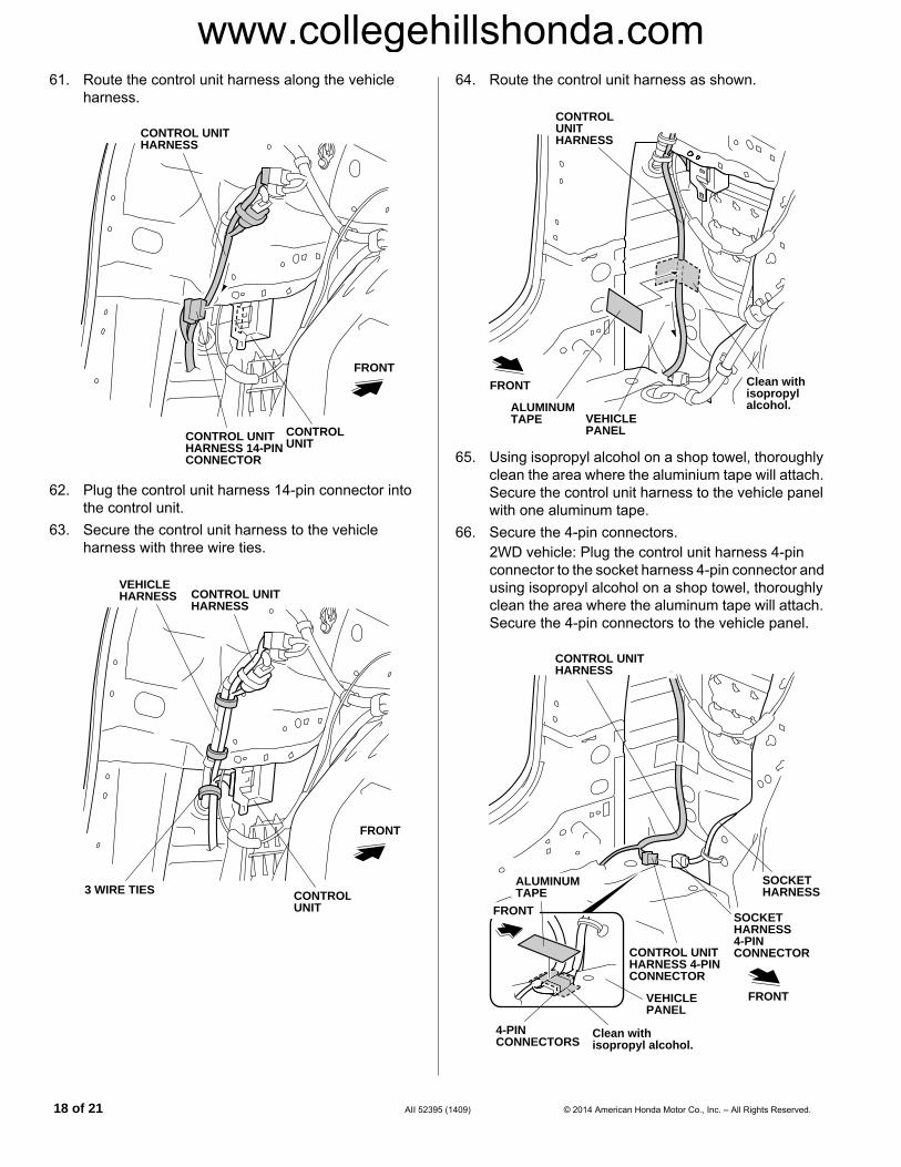
61. Route the control unit harness along the vehicleharness.
QA12101AX
CONTROL UNIT HARNESS
FRONT
CONTROL UNIT HARNESS 14-PIN CONNECTOR
CONTROL UNIT
62. Plug the control unit harness 14-pin connector into the control unit.
63. Secure the control unit harness to the vehicle harness with three wire ties.
QA12102AX
CONTROL UNIT HARNESS
FRONT
3 WIRE TIES
VEHICLE HARNESS
CONTROL UNIT
18 of 21 AII 52395
(1409) © 2014 American Honda Motor Co., Inc. – All Rights Reserved.64. Route the control unit harness as shown.
QA12103BX
Clean with isopropyl alcohol.ALUMINUM
TAPE VEHICLE PANEL
CONTROL UNIT HARNESS
FRONT
65. Using isopropyl alcohol on a shop towel, thoroughly clean the area where the aluminium tape will attach. Secure the control unit harness to the vehicle panel with one aluminum tape.
66. Secure the 4-pin connectors.2WD vehicle: Plug the control unit harness 4-pin connector to the socket harness 4-pin connector and using isopropyl alcohol on a shop towel, thoroughly clean the area where the aluminum tape will attach. Secure the 4-pin connectors to the vehicle panel.
QA61301AE
CONTROL UNIT HARNESS
FRONT
Clean with isopropyl alcohol.
VEHICLE PANEL
CONTROL UNIT HARNESS 4-PIN CONNECTOR
4-PIN CONNECTORS
SOCKET HARNESS
SOCKET HARNESS 4-PIN CONNECTOR
ALUMINUM TAPE
FRONT

www.collegehillshonda.com
4WD vehicle: Plug the control unit harness 4-pin connector to the socket harness 4-pin connector and secure the 4-pin connectors to the vehicle harness with one wire tie.QA12104BX
CONTROL UNIT HARNESS
FRONT
WIRE TIE
VEHICLE HARNESS
CONTROL UNIT HARNESS 4-PIN CONNECTOR
4-PIN CONNECTORS
SOCKET HARNESS
SOCKET HARNESS 4-PIN CONNECTOR
FRONT
67. Install the connector clip to the fuse case on the control unit harness.
QA12106AX
TRAILER UNIT HARNESS
VEHICLE PANEL
FRONTFUSE CASE
CONNECTOR CLIP
CLIPFUSE CASE
68. Route the fuse case on the control unit harness as shown, and secure it to the vehicle panel with connector clip installed in step 67.
69. Secure the clip on the trailer unit harness to the vehicle panel as shown.
© 2014 American Honda Motor Co., Inc. – All Rights Reserved. AII 5239
5 (1409) 19 of 2170. Using a pushpin, pierce the center of the scribe mark on the left rear side trim panel. NOTE: Some left rear side trim panels may not have the scribe line. If not, use the measurement shown.
LEFT REAR SIDE TRIM PANEL
20 mm HOLE SAW
PUSHPIN
SCRIBE MARK
3 mm DRILL BIT
DRILL
20 mm
20 mm
71. While wearing an eye protection, drill the mark on the left rear side trim panel with a 3 mm drill bit. Enlarge the 3 mm hole to 20 mm using 20 mm hole saw.
72. Using a utility knife, cut the left rear side trim panel along the scribe line as shown. Remove any burrs.
UTILITY KNIFE
SCRIBE LINE
Cut off.
LEFT REAR SIDE TRIM PANEL

www.collegehillshonda.com
73. Under the dashboard, install the 7.5A fuse into thefuse box as shown.
QA12401AX
FUSE BOX
Plug in here.
7.5A FUSE
FRONT VIEWFUSE BOX
74. With the help of an assistant, reinstall the rear under cover and the rear bumper.
QA22502AX
TRAILER HITCH
HITCH PIN CLIP
HITCH PIN
BALL MOUNT
HITCH PIN
75. Secure the ball mount to the trailer hitch with the hitch pin and hitch pin clip.
20 of 21 AII 52395
76. Remove and discard the vehicle clip, and install the new clip to the left D-pillar trim.
Q0N3001AE
LEFT D-PILLAR TRIM
FRONT
WITH SIDE CURTAIN AIRBAG
LEFT D-PILLAR TRIM
NEW CLIP
VEHICLE CLIPDiscard.
77. Check the overlap between the headliner and the D-pillar trim. NOTE: Check and adjust the overlap as described in the Service Manual.
78. Reinstall the left D-pillar trim. NOTE: Make sure the side curtain airbag is not tucked under the clip. Do not push the D-pillar trim excessively.
79. Check that all wire harnesses are routed properly and all connectors are plugged in.
80. Reinstall all removed parts.81. Reconnect the negative cable to the battery.82. Press and hold the radio power button for two
seconds to restore the radio and navi (if equipped) system functions.
83. Reset the clock.
(1409) © 2014 American Honda Motor Co., Inc. – All Rights Reserved.

www.collegehillshonda.com
Give a copy of this page to your customerWhenever you remove the hitch pin clip, the hitch pin, and the ball mount, store them securely in the cargo area. Install the receiver cover into the opening at the end of the trailer hitch. When you reinstall the ball mount, store the receiver cover in the cargo area.
QA12404AX
RECEIVER COVER
TRAILER HITCH
Install the ball mount the trailer hitch using a hitch pin clip and hitch pin.
QA22502AX
TRAILER HITCH
HITCH PIN CLIP
HITCH PIN
BALL MOUNT
HITCH PIN
After the first 600 miles (1,000 km) of towing, have your Honda Dealer re-check the tightness of the trailer hitch bolts.
© 2014 American Honda Motor Co., Inc. – All Rights Reserved. AII 52395 (1409) 21 of 21