Embed Size (px)
Citation preview

1
G-SERIES THE FLEXIBLE MANUFACTURING SYSTEM
G-SERIES THE FLEXIBLE MANUFACTURING SYSTEM

2
THE G-SERIES
The G-SeriesG-Modules are modularly built machining centers in three different installation sizes, designed for application in run production in the automobile industry. All sizes are available in single or twin-spindle machine versions.

3

44
The requirements for a modern manufacturing system are as diverse as they are antithetic: more flexibility, more productivity, lower investment costs and guaranteed future at the same time.The G-Series represented a development of a manufacturing system which is pioneering for the machine tool industry.
Modularity is the GROB standardThe manufacturing system (of the) G-Series is designed for maximum flexibility on both, the machine side and the process side. For this reason, the machining centers follow a strict modular structure. They are independent modules which, depending on customer demand in various different stages of expansion, are assembled using a modular system.
STRUCTURE
A X I S C O N F I G U R AT I O N
• X and Z movement are located within the spindle (no quill)
• Y axis is located within the workpiece• Tilting axes located within the workpiece
F E AT U R E S
• Modular structure• X and Z axes with maximum dynamics• Maximum stiffness levels • Ideal chip shedding (overhead working)• Horizontal machining • Highest levels of flexibility • Easy accessibility
(loading possible from the front and from above)• High levels of energy efficiency• Minimal chip-to-chip times
Schematic representation of a 2-spindle machineSchematic representation of a 1-spindle machine

55
De-coupling of the axesThe development of the G-Series included splitting the mov-ing axes, for dynamic and stiffness reasons, into the tool side and the component side. With the aid of this decoup-ling, the machining centers can be structured in accordance with the modular principle to produce a very compact unit.
Modular structureThe basic principle of each machining module of the G-Series is the same. The module can optionally be fitted with one or two spindle slide units and with one or two spindles. They are arranged horizontally and have a cross-slide with X - Z movement. The component bridge moves vertically in the Y direction. Following this fundamental principle, the G-Series is offered in three different sizes: One or two spin-dles, with one or two workpieces, with, in each case, A, B or A / B axes.
The subdivision of the main modules allows having a modu-larized manufacturing process with reduced throughput times and minimized manufacturing costs. This leads to con-sistent reduction in the module diversity along with a variety of combination possibilities.
Optimal flexibilityThe G-Series can react rapidly and flexibly to tool changes or changes in type. The modules can easily be reused on the basis of this modular system.
High levels of economyThe G-Series is optimized for both, wet and dry machining. The entire system only takes up a small floor area and is optimized for short throughput times within the framework of the GROB production system.
Absolutely future-proofThe innovation cycles are getting more and more shorter and product changes need to be realized within a very short period of time, in the shortest time period, particularly in the automobile industry. These requirements are fulfilled excel-lently by the G-Series. It is particularly changeover-friendly and can be extended at any time. With its installation and commissioning effort which is reduced to a minimum, the G-Series is the flexible partner for all manufacturing tasks and for any process modification.
Example: Modular structure of the main components of the G500
ADVANTAGES

2700
(G
300E
: 310
0)
4500 (G300E: 4000)
2500
(G
300E
: 270
0)
6
ØB
ØA
L
ØA
ØB
H
Technical data G300 G300E
Working Travel in X / Y / Z [mm] 600 / 770 / 685 1,100 / 655 / 685
Speed (max.) in X / Y / Z [m / min]
90 / 42* / 100 90 / 75 / 90
Acceleration (max.) X / Y / Z [m / s²]
6 / 3.6 / 15 6 / 5 / 12
Feed force (max.) in X / Y / Z [kN]
8 / 8 / 8
Chip-to-chip time t1 as per VDI 2852 (min) [s]
3.5 3.0
Weight [kg] 13,000 15,000
Magazine variantsMagazine variants
Tilting axesTilting axes
HSK-A63 G300:
• 34 pockets (standard)• 40 pockets (optional)
Side view Plan view
BASE MACHINE
A axis G300 / G300E:• ØA: 800 / 800 mm• L: 790 / 1,300 mm• 11 / 6 fluid connections
B axis G300:• ØB: 600 mm• H: 550 mm• 8 fluid connections
A / B axis G300:• ØA: 800 mm• ØB: 600 mm• 8 fluid connections
G-SERIES G300, G300E
Pick-up disc-type magazine
Double disc-type magazine with tool changer
HSK-A63 G300E:
• 52 pockets (standard)
* on request 61 m / min

77
The innovative concept of the G-Series is ideal for 5-axis machining and guarantees optimal accessibility to the work area. The machines consist of well-proven components and are especially characterized by high rigidity and dynamic response.
3100
4000
3100
(G32
0E: 2
700)
L
ØA
ØB
ØA
ØB
ØBØB
H
Magazine variantsMagazine variants
Tilting axesTilting axes
Double disc-type magazine with tool changer
HSK-A63:
• 49 pockets per spindle
Side view Plan view
BASE MACHINE
A axis G320 / G320E:• ØA: 800 / 800 mm• L: 1,450 / 1,300 mm• 2 x 10 / 6 fluid connections
B axis G320 / G320E: • ØB: 2 x 695 / 545 mm• H: 435 / 435 mm• 2 x 9 / 6 fluid connections
A / B axis G320 / G320E: • ØA: 800 / 800 mm• ØB: 2 x 598 / 545 mm• 2 x 9 / 6 fluid connections
Technical data G320 G320E
Working Travel in X / Y / Z [mm] 600 / 655 / 685 550 / 655 / 685
Speed (max.) in X / Y / Z [m / min]
90 / 75 / 100 90 / 75 / 90
Acceleration (max.) X / Y / Z [m / s²]
7 / 5 / 15 7 / 5 / 15
Feed force per spindle (max.) in X / Y / Z [kN]
5 / 5 / 6
Spindle spacing [mm] 700 550
Chip-to-chip time t1 as per VDI 2852 (min) [s]
2.3 2.5
Weight [kg] 17,000 15,000
G-SERIES G320, G320E
8
3100
4900
2800
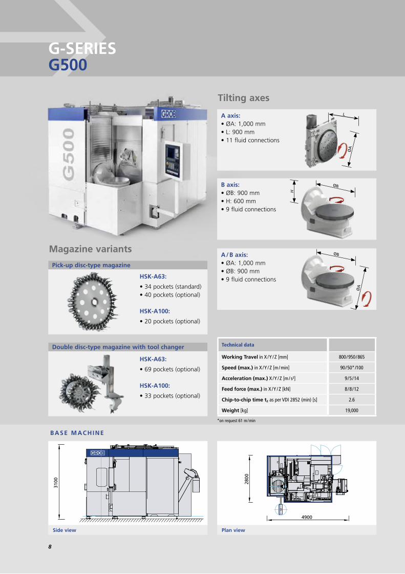
G-SERIES G500
ØB
ØA
L
ØA
ØB
H
Magazine variantsMagazine variants
Pick-up disc-type magazine
HSK-A63:
• 34 pockets (standard)• 40 pockets (optional)
HSK-A100:
• 20 pockets (optional)
Double disc-type magazine with tool changer
HSK-A63:
• 69 pockets (optional)
HSK-A100:
• 33 pockets (optional)
Tilting axesTilting axes
Side view Plan view
BASE MACHINE
Technical data
Working Travel in X / Y / Z [mm] 800 / 950 / 865
Speed (max.) in X / Y / Z [m / min] 90 / 50* /100
Acceleration (max.) X / Y / Z [m / s²] 9 / 5 / 14
Feed force (max.) in X / Y / Z [kN] 8 / 8 / 12
Chip-to-chip time t2 as per VDI 2852 (min) [s] 2.6
Weight [kg] 19,000
A axis:• ØA: 1,000 mm• L: 900 mm• 11 fluid connections
B axis:• ØB: 900 mm• H: 600 mm• 9 fluid connections
A / B axis:• ØA: 1,000 mm• ØB: 900 mm• 9 fluid connections
*on request 61 m / min

99
3500
4700
3600
L
ØA
ØB
ØA
ØB
ØBØB
H
Magazine variantsMagazine variants
HSK-A63:
• 69 pockets per spindle (standard)
HSK-A100:
• 33 pockets per spindle (optional)
Tilting axesTilting axes
Side view Plan view
BASE MACHINE
Technical data
Working Travel in X / Y / Z [mm] 750 / 840 / 865
Speed (max.) in X / Y / Z [m / min] 90 / 75 / 100
Acceleration (max.) X / Y / Z [m / s²] 6 / 6 / 14
Feed force per spindle (max.) in X / Y / Z [kN] 6 / 6 / 10
Spindle pitch [mm] 800
Chip-to-chip time t1 as per VDI 2852 (min) [s] 2.4 (HSK-A63)
2.9 (HSK-A100)
Weight [kg] 23,000
A axis:• ØA: 1,000 mm• L: 1,770 mm• 2 x 11 fluid connections
B axis:• ØB: 2 x 798 mm• H: 510 mm• 2 x 9 fluid connections
A / B axis:• ØA: 1,000 mm• ØB: 2 x 798 mm• 2 x 9 fluid connections
Double disc-type magazine with tool changer
The machining centers of the G-Series are ideal for multi-spindle applications. Since the spindle slide moves exclusively in the X and Z axis, it is easy to configure with two or four spindles. This cross-slide structure also guarantees the highest levels of stiffness and stability, even with multi-spindle technology. Multi-spindle machines are the most economical facility for serial chip-forming. They offer both, maximum energy efficiency and minimum maintenance and operating costs.
G-SERIES G520
10
4300
5100
3700
ØB
ØA
L
ØA
ØB
H
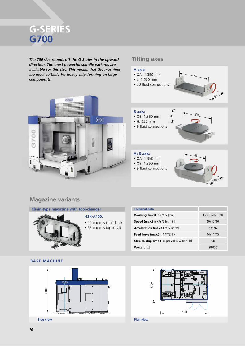
Tilting axesTilting axes
Technical data
Working Travel in X / Y / Z [mm] 1,250 / 920 / 1,160
Speed (max.) in X / Y / Z [m / min] 60 / 50 / 60
Acceleration (max.) X / Y / Z [m / s²] 5 / 5 / 6
Feed force (max.) in X / Y / Z [kN] 14 / 14 / 15
Chip-to-chip time t2 as per VDI 2852 (min) [s] 4.8
Weight [kg] 28,000
Magazine variantsMagazine variants
Chain-type magazine with tool-changer
HSK-A100:
• 49 pockets (standard)• 65 pockets (optional)
Side view Plan view
BASE MACHINE
A axis:• ØA: 1,350 mm• L: 1,660 mm• 20 fluid connections
B axis:• ØB: 1,350 mm• H: 920 mm• 9 fluid connections
A / B axis:• ØA: 1,350 mm• ØB: 1,350 mm• 9 fluid connections
The 700 size rounds off the G-Series in the upward direction. The most powerful spindle variants are available for this size. This means that the machines are most suitable for heavy chip-forming on large components.
G-SERIES G700

1111
Technical data
Working Travel in X / Y / Z [mm] 690 / 920 / 1,160
Speed (max.) in X / Y / Z [m / min] 50 / 50 / 60
Acceleration (max.) X / Y / Z [m / s²] 6 / 5 / 7
Feed force per spindle (max.) in X / Y / Z [kN] 6 / 6 / 12
Spindle pitch [mm] 380 – 520
Chip-to-chip time t2 as per VDI 2852 (min) [s] 6
Weight [kg] 28,000
4300
5100
3700
ØB
ØA
L
ØA
ØB
H
Magazine variantsMagazine variants
Chain-type magazine with tool-changer
HSK-A100:
• 24 pockets per spindle (standard)
• 32 pockets per spindle (optional)
Tilting axesTilting axes
Side view Plan view
BASE MACHINE
A axis:• ØA: 1,350 mm• L: 1,660 mm• 20 fluid connections
B axis:• ØB: 1,350 mm• H: 920 mm• 9 fluid connections
A / B axis:• ØA: 1,350 mm• ØB: 1,350 mm• 9 fluid connections
G-SERIES G720

12
SPINDLES
In order to provide optimum process structuring, there is a wide selection of spindle variants for every G-Module. As a preference, we fit spindles developed and manufactured by GROB itself, since these are matched to the G-Modules in an optimum manner. This is characterized primarily by good accessibility and simple maintenance.
GROB spindles are characterized by:• best mechanical features • Long-life cycle• universal applicability• maximum GROB quality • suitable for all common
coolants and lubricants
GROB spindle diagnosis: The GROB spindle diagnosis represents a special characteristic. This facilitates long-term opera-tion of the spindle in the above performance spectrum. In addition, we can avoid wear-related downtimes, because critical wear can be detected in good time. This means that spindle replacement can be undertaken at a planned service interval, thus considerably reducing the risk of unanticipated downtimes as a result of wear. At the same time we ensure that the maximum service life of the spindle can be achieved.
Spindle variants
Tool holder for short hollow taper shank to DIN 69 893
HSK-A63 HSK-A63 HSK-A63 HSK-A63 HSK-A100 HSK-A100 HSK-A100 HSK-A100
Spindle bearing Spindle diameter on front bearing [mm]
70 70 70 80 100 100 110 120
Speed nmax [1 / min] 12,000 18,000 12,000 8,000 6,000 10,000 9,000 7,200
Drive power rating ED 100 % / 40 % [kW] 29 / 39 29 / 39 40 / 52 20 / 25 20 / 26 20 / 26 54 / 65 95 / 125
Spindle torque ED 100 % / 40 % [Nm] 34.6 / 46.6 34.6 / 46.6 63.7 / 82.8 159 / 199 262 / 340 262 / 340 470 / 575 1,270 / 1,650
G300 / G300E - - - -
G320 / G320E - - - -
G500 -
G520 - -
G700 - - - -
G720 - - - - - -
available - not available

1313
Drive variantsDrive variants
Standard:• Ball screw drive in all linear
axes with direct measuring system
Linear motor system:• Linear motors in the linear axes• Reduced chip-to-chip time
Accuracy: (ISO 230-2 date a 2006-03-15)
• directional accuracy of positioning A on X / Y / Z axis [mm] 0.006 • directional repeatability of positioning on X / Y / Z axis [mm] < 0.0025 < 0.003 for G700 + G720
Control systemsControl systems
• Siemens (Standard)• Fanuc (Optional)• Bosch Rexroth (Optional)
Workpiece clamping / clamping fixturesWorkpiece clamping / clamping fixtures
• Integrated clamping fixture• Adapter plate system• Zero-point clamping systems• Clamping fixture changer• Electromechanical clamping fixture
Special designSpecial design
Depending on the customer requirements we can offer special models • Cross-feed spindle • Drilling heads • Special spindles • Spindle configuration a 4-spindle G-Module a 1-spindle configuration in double spindle G-Modules
Hydraulic-free machineHydraulic-free machine
All movements, workpiece and tool clamping devices are realized with NC axes. The latest GROB development has been submitted for patenting.
Drive variants Linear motor system
X axis Y axis Z axis
G300
G300E - - -
G320 / G320E /
G500
G520
G700 - - -
G720 - - -
Available on request - not available
EXPANSION VARIANTS
14
OPTIONS
• Decentralized mechanical emulsion mist separator with two demister stages, designed as a metal / plastic unit
• Decentralized electrostatic oil mist separator • Evaluation element for reducing the required extraction output
Extraction unitsExtraction units
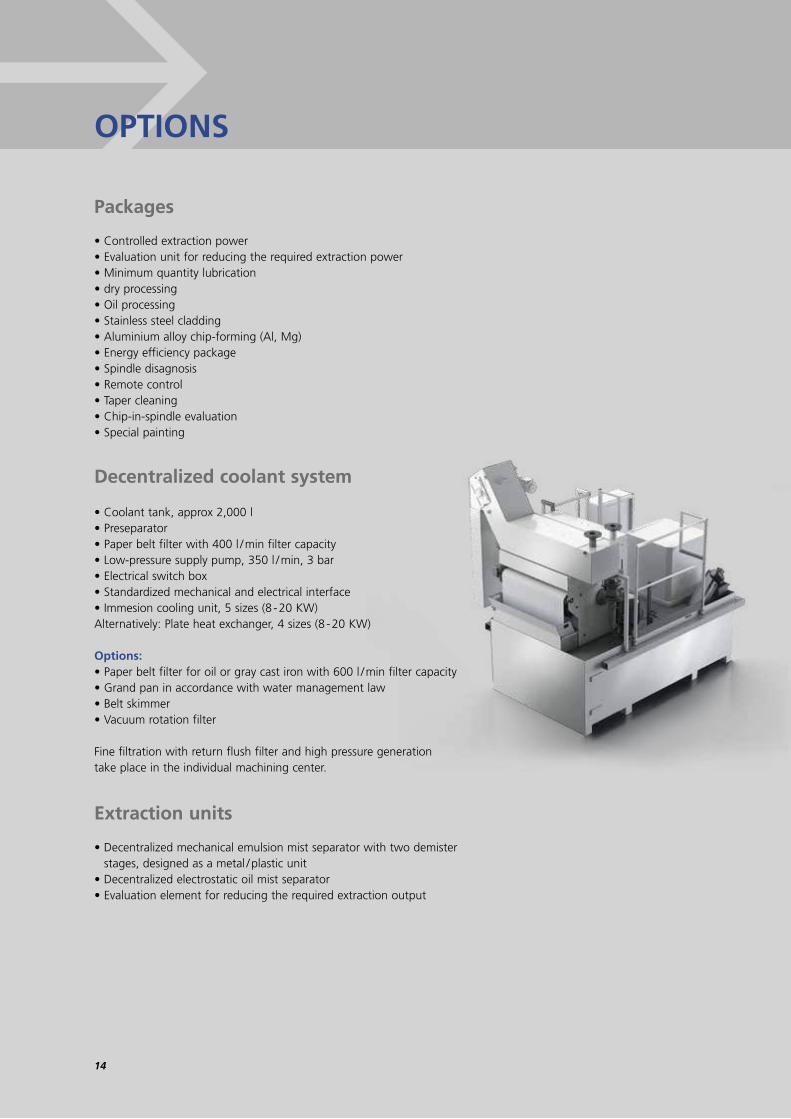
• Coolant tank, approx 2,000 l• Preseparator• Paper belt filter with 400 l / min filter capacity• Low-pressure supply pump, 350 l / min, 3 bar• Electrical switch box• Standardized mechanical and electrical interface• Immesion cooling unit, 5 sizes (8 - 20 KW) Alternatively: Plate heat exchanger, 4 sizes (8 - 20 KW)
Options:• Paper belt filter for oil or gray cast iron with 600 l / min filter capacity• Grand pan in accordance with water management law• Belt skimmer • Vacuum rotation filter
Fine filtration with return flush filter and high pressure generation take place in the individual machining center.
Decentralized coolant systemDecentralized coolant system
PackagesPackages
• Controlled extraction power • Evaluation unit for reducing the required extraction power • Minimum quantity lubrication• dry processing • Oil processing • Stainless steel cladding • Aluminium alloy chip-forming (Al, Mg) • Energy efficiency package • Spindle disagnosis • Remote control • Taper cleaning • Chip-in-spindle evaluation • Special painting

15
The structure of all machining centers in the G-Series allows an efficient loading of the work area from the front and from above. The Y axes takes on the vertical auxiliary movement required for loading. This means that an additional lifting stoke is not required. Since all loading equipment was developed and manufactured by GROB, optimum matching of the individual components is guaranteed. The entire system (machine, device, process and automation) from a single supplier ensures optimum conditions – without compromise.
Efficient loadingEfficient loading
Technical modifications reserved.
Cartesian gantry
The Cartesian gantry is intended for fully automatic direct loading of a G-Module from above and is also suitable for very large workpiece dimensions. Designed as an I or H loader, it possesses one or two vertical axes per carrier.
Agile gantryThe newly developed gantry is characterized by very high acceleration rates and velocities as well as by very high positioning accuracy and is suitable for loading workpieces of average dimensions. A further advantage of the system is the ease with which it can be adapted to new types of workpieces. The minimum number of components guarantees the highest availability.
Manual shift part changer
Loading processes which are decoupled from transport are achieved with shift part changers. The machine is loaded in two stages. The finished workpieces are removed from the machine with the free loading fork; the unmachined parts are then fed into the machine. This system supports loading from single and twin-spindle machines.
TOP LOADING
FRONT LOADING
Automatic shift part changer
The automatic shift part changer is generally equipped with a gantry. The workflow corresponds to that of the manual shift part changer. Loading with an agile loading gantry and an automatic shift part changer is the GROB standard for automated, decoupled loading processes which guarantee that idle time is kept to a minimum during the machiningprocess.
Direct loading with the kinematric gantry
The kinematic gantry with an articulated arm, is the most advanced solution of GROB for direct loading of G-modules and modular special machines. The arrangement of the X-beam in front of the machine allows a low stack height with simultaneous access to repair work above the machine. The stroke movement is performed by a specially developed articulating arm for GROB, in which torque motors are used as a drive. Therefore both serial as well as parallel work sequences can be loaded. And, as usual, at GROB, one-or two-spindle - machines.
Swivelling changer
The Swivelling changer decouples the transport from the loading process, which can be conducted manually as well as through a gantry. It is suitable for both, partial and fully automatic loading. A Swivelling changer can load two machines, one immediately after the other. They can be set up facing one another, which is a space-efficient solution.
LOADING SYSTEMS

www.grobgroup.com
GROB-WERKE Mindelheim, Germany
GROB SYSTEMS Bluffton, Ohio, USA
B. GROB DO BRASIL São Paulo, Brazil
GROB MEXICO Querétaro, Mexico
GROB MACHINE TOOLS Birmingham, Great BritainGROB RUSSLAND Moscow, Russia
GROB MACHINE TOOLS Hyderabad, India
GROB KOREA Seoul, South KoreaGROB MACHINE TOOLS Shanghai, China
GROB MACHINE TOOLS Beijing, China GROB MACHINE TOOLS Dalian, China
GROB KOREA Co. Ltd. Seoul, SOUTH KOREAPhone: +82 31 8041-3130E-mail: [email protected]
GROB MACHINE TOOLS (BEIJING) Co. Ltd. Beijing, P.R. CHINAPhone: +86 10 6480-3711E-mail: [email protected]
GROB MACHINE TOOLS (BEIJING) Co. Ltd. Shanghai, P.R. CHINAPhone: +86 21 3763-3018E-mail: [email protected]
GROB MACHINE TOOLS INDIA Pvt. Ltd.Hyderabad, INDIAPhone: +91 40 4202-3336E-mail: [email protected]
GROB RUSSLAND GMBHMoscow, RUSSIAPhone: +7 495 624-0586E-mail: [email protected]
GROB MACHINE TOOLS U.K. Ltd.Birmingham, GREAT BRITAINPhone: +44 121 366-9848E-mail: [email protected]
GROB MEXICO S.A. de C.V.Querétaro, MEXICOPhone: +52 442 713-6602E-mail: [email protected]
GROB HUNGARIA KFT.Györ, HUNGARYE-mail: [email protected]
GROB-WERKE GmbH & Co. KGMindelheim, GERMANYPhone: +49 8261 996-0Fax: +49 8261 996-268E-mail: [email protected]
B. GROB DO BRASIL S.A.São Paulo, BRAZILPhone: +55 11 4367-9100Fax: +55 11 4367-9101E-mail: [email protected]
GROB SYSTEMS, INC. Bluffton, Ohio, USAPhone: +1 419 358-9015Fax: +1 419 369-3330E-mail: [email protected]
GROB MACHINE TOOLS (DALIAN) Co. Ltd. Dalian, P.R. CHINAPhone: +86 411 3926-6488Fax: +86 411 3926-6589E-mail: [email protected]
GROB HUNGARIA Györ, Hungary
© G
RO
B-W
ERK
E G
mb
H &
Co
. KG
· 08
/201
4/EN