Embed Size (px)
Citation preview
1
The Flaker and DCM series of ice machines use a completelydifferent ice making process than the cuber style of icemaker.The Flaker has a continuous ice making process that does notincorporate a harvest cycle it will simply continue constant iceproduction until the units bin control is satisfied . The unit willbring water on as needed to keep the reservoir and evaporatorfull. In the next few slides we will discuss the details of theoperating sequence for the Flaker and DCM products.
2
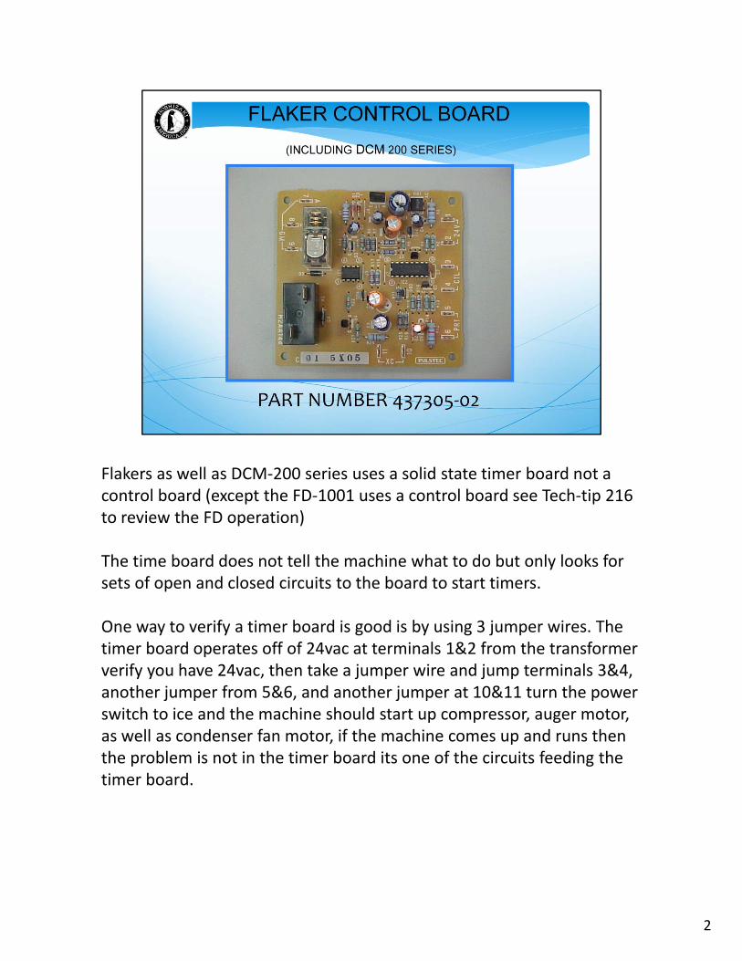
Flakers as well as DCM‐200 series uses a solid state timer board not a control board (except the FD‐1001 uses a control board see Tech‐tip 216 to review the FD operation)
The time board does not tell the machine what to do but only looks for sets of open and closed circuits to the board to start timers.
One way to verify a timer board is good is by using 3 jumper wires. The timer board operates off of 24vac at terminals 1&2 from the transformer verify you have 24vac, then take a jumper wire and jump terminals 3&4, another jumper from 5&6, and another jumper at 10&11 turn the power switch to ice and the machine should start up compressor, auger motor, as well as condenser fan motor, if the machine comes up and runs then the problem is not in the timer board its one of the circuits feeding the timer board.
3
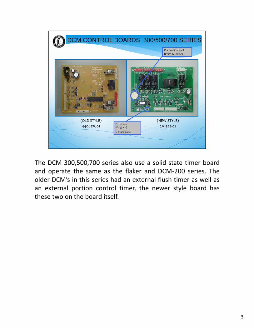
The DCM 300,500,700 series also use a solid state timer boardand operate the same as the flaker and DCM‐200 series. Theolder DCM’s in this series had an external flush timer as well asan external portion control timer, the newer style board hasthese two on the board itself.
4
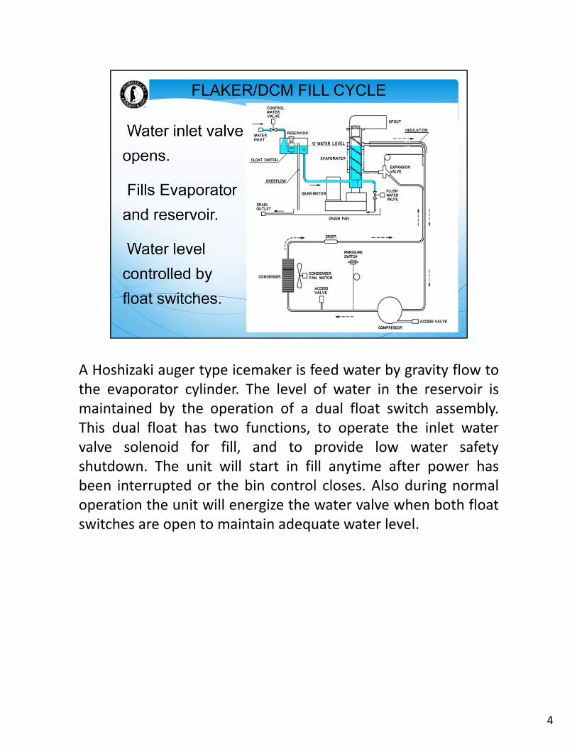
A Hoshizaki auger type icemaker is feed water by gravity flow tothe evaporator cylinder. The level of water in the reservoir ismaintained by the operation of a dual float switch assembly.This dual float has two functions, to operate the inlet watervalve solenoid for fill, and to provide low water safetyshutdown. The unit will start in fill anytime after power hasbeen interrupted or the bin control closes. Also during normaloperation the unit will energize the water valve when both floatswitches are open to maintain adequate water level.
5
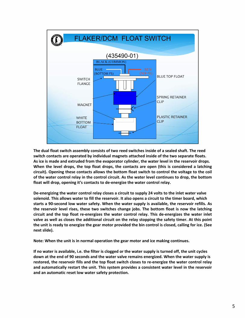
The dual float switch assembly consists of two reed switches inside of a sealed shaft. The reedswitch contacts are operated by individual magnets attached inside of the two separate floats.As ice is made and extruded from the evaporator cylinder, the water level in the reservoir drops.When the level drops, the top float drops, the contacts are open (this is considered a latchingcircuit). Opening these contacts allows the bottom float switch to control the voltage to the coilof the water control relay in the control circuit. As the water level continues to drop, the bottomfloat will drop, opening it’s contacts to de‐energize the water control relay.
De‐energizing the water control relay closes a circuit to supply 24 volts to the inlet water valvesolenoid. This allows water to fill the reservoir. It also opens a circuit to the timer board, whichstarts a 90‐second low water safety. When the water supply is available, the reservoir refills. Asthe reservoir level rises, these two switches change jobs. The bottom float is now the latchingcircuit and the top float re‐energizes the water control relay. This de‐energizes the water inletvalve as well as closes the additional circuit on the relay stopping the safety timer. At this pointthe unit is ready to energize the gear motor provided the bin control is closed, calling for ice. (Seenext slide).
Note: When the unit is in normal operation the gear motor and ice making continues.
If no water is available, i.e. the filter is clogged or the water supply is turned off, the unit cyclesdown at the end of 90 seconds and the water valve remains energized. When the water supply isrestored, the reservoir fills and the top float switch closes to re‐energize the water control relayand automatically restart the unit. This system provides a consistent water level in the reservoirand an automatic reset low water safety protection.
6
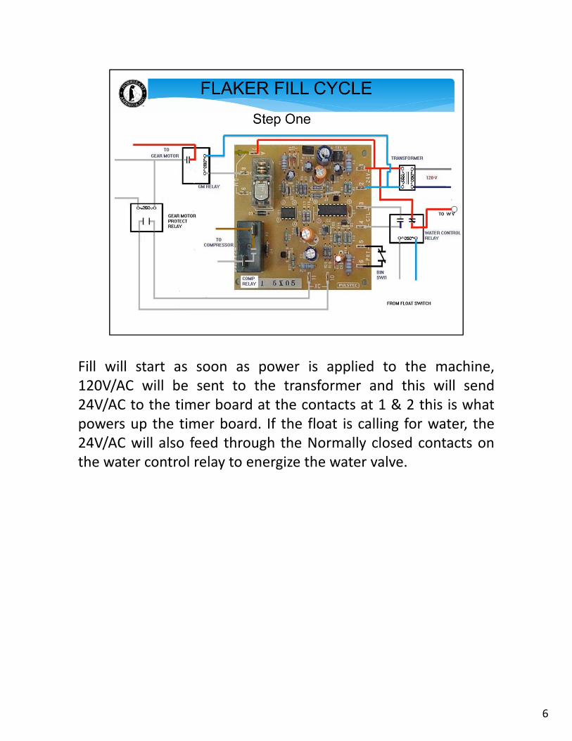
Fill will start as soon as power is applied to the machine,120V/AC will be sent to the transformer and this will send24V/AC to the timer board at the contacts at 1 & 2 this is whatpowers up the timer board. If the float is calling for water, the24V/AC will also feed through the Normally closed contacts onthe water control relay to energize the water valve.
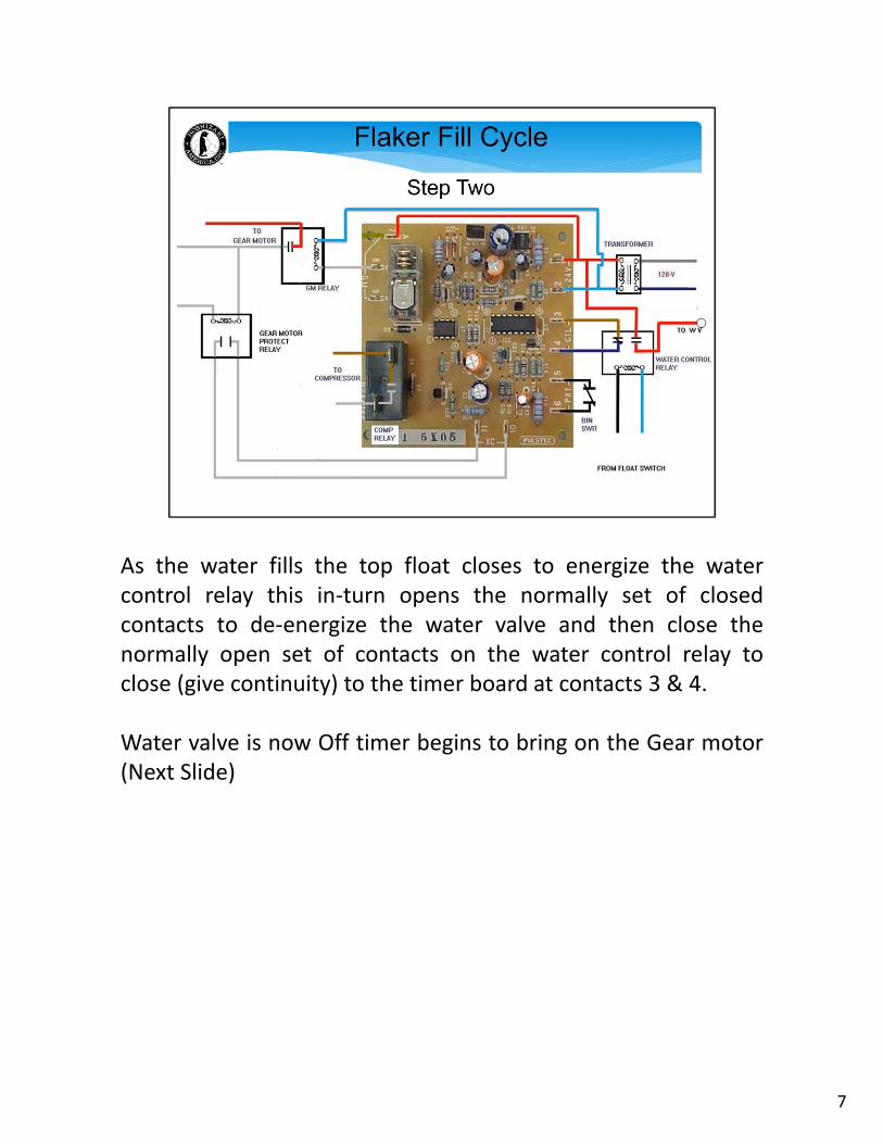
As the water fills the top float closes to energize the watercontrol relay this in‐turn opens the normally set of closedcontacts to de‐energize the water valve and then close thenormally open set of contacts on the water control relay toclose (give continuity) to the timer board at contacts 3 & 4.
Water valve is now Off timer begins to bring on the Gear motor(Next Slide)
7
8
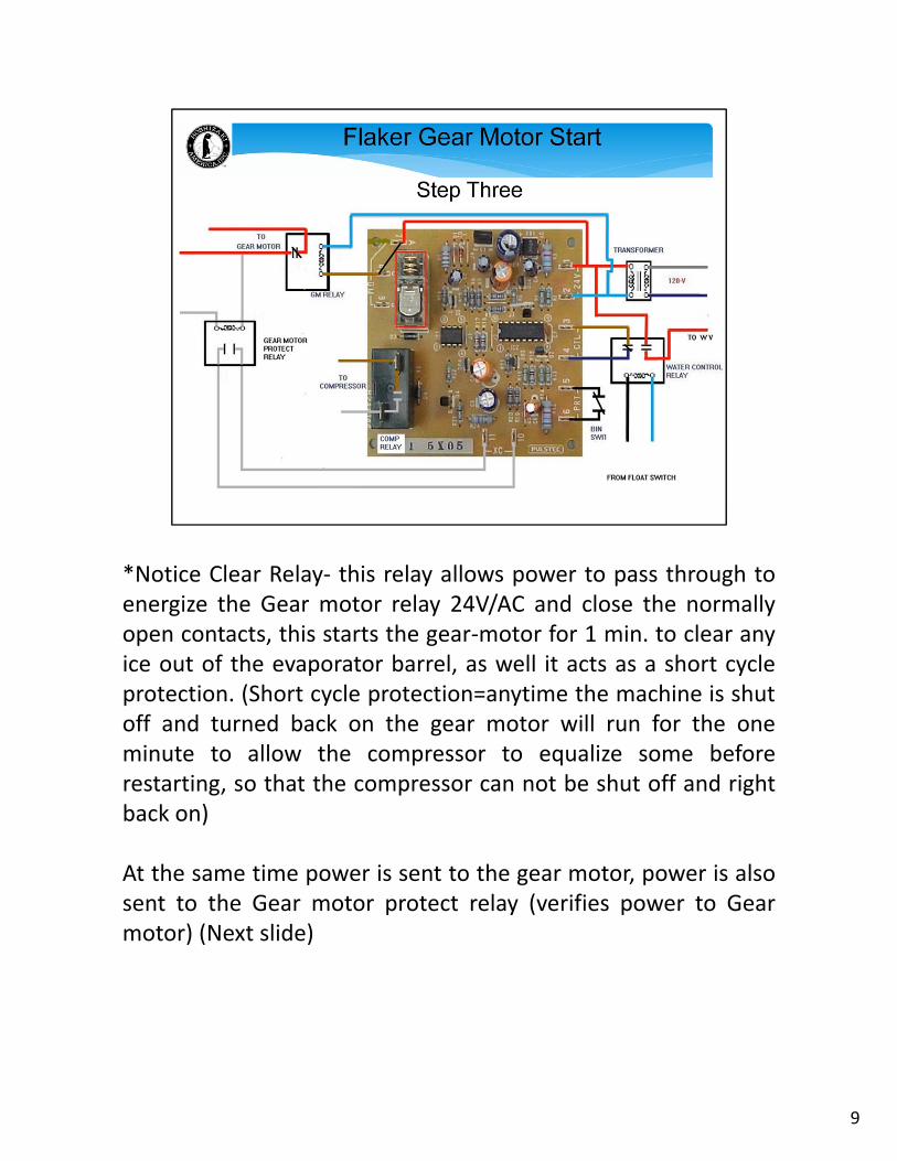
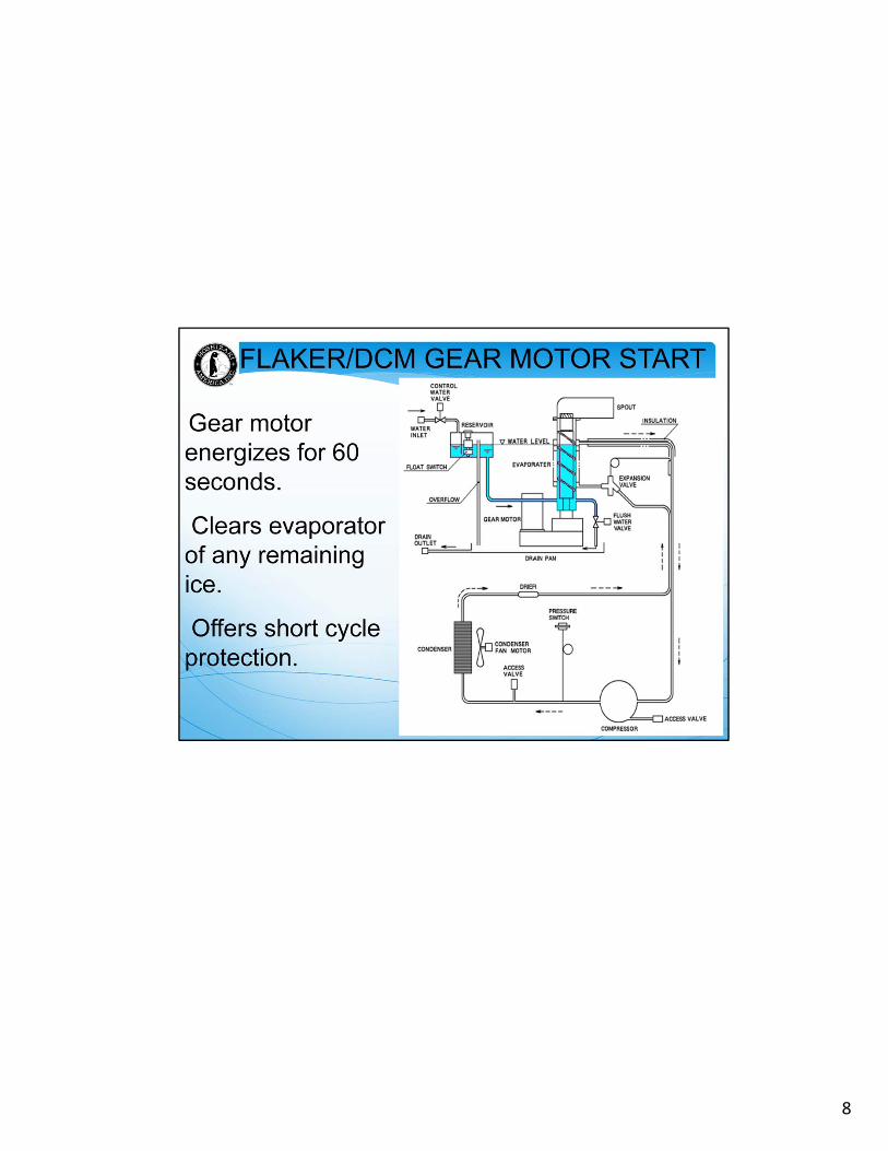
*Notice Clear Relay‐ this relay allows power to pass through toenergize the Gear motor relay 24V/AC and close the normallyopen contacts, this starts the gear‐motor for 1 min. to clear anyice out of the evaporator barrel, as well it acts as a short cycleprotection. (Short cycle protection=anytime the machine is shutoff and turned back on the gear motor will run for the oneminute to allow the compressor to equalize some beforerestarting, so that the compressor can not be shut off and rightback on)
At the same time power is sent to the gear motor, power is alsosent to the Gear motor protect relay (verifies power to Gearmotor) (Next slide)
9
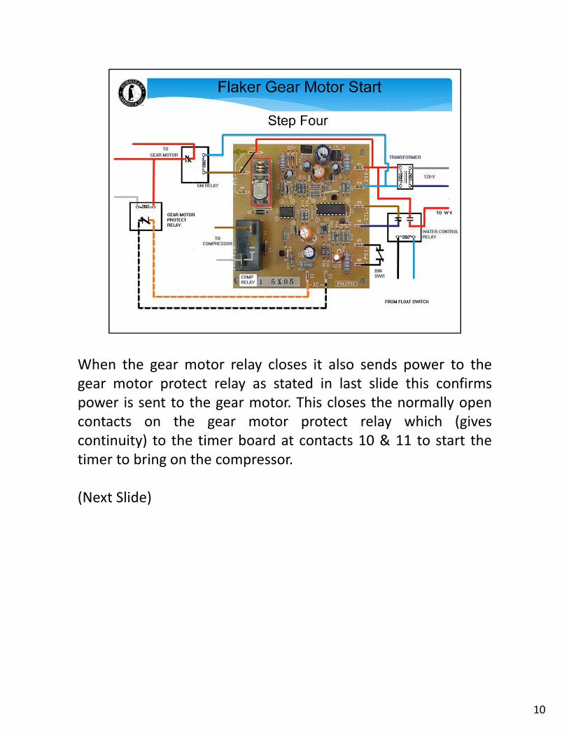
When the gear motor relay closes it also sends power to thegear motor protect relay as stated in last slide this confirmspower is sent to the gear motor. This closes the normally opencontacts on the gear motor protect relay which (givescontinuity) to the timer board at contacts 10 & 11 to start thetimer to bring on the compressor.
(Next Slide)
10
11
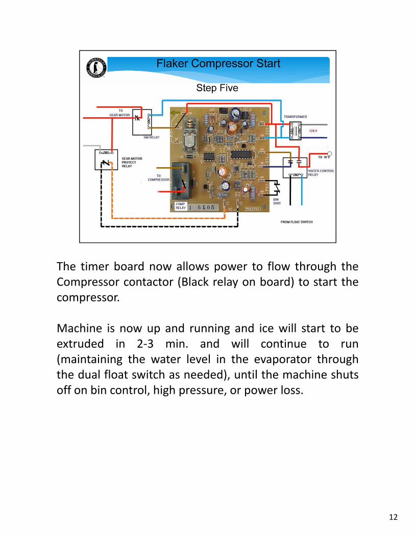
The timer board now allows power to flow through theCompressor contactor (Black relay on board) to start thecompressor.
Machine is now up and running and ice will start to beextruded in 2‐3 min. and will continue to run(maintaining the water level in the evaporator throughthe dual float switch as needed), until the machine shutsoff on bin control, high pressure, or power loss.
12
13
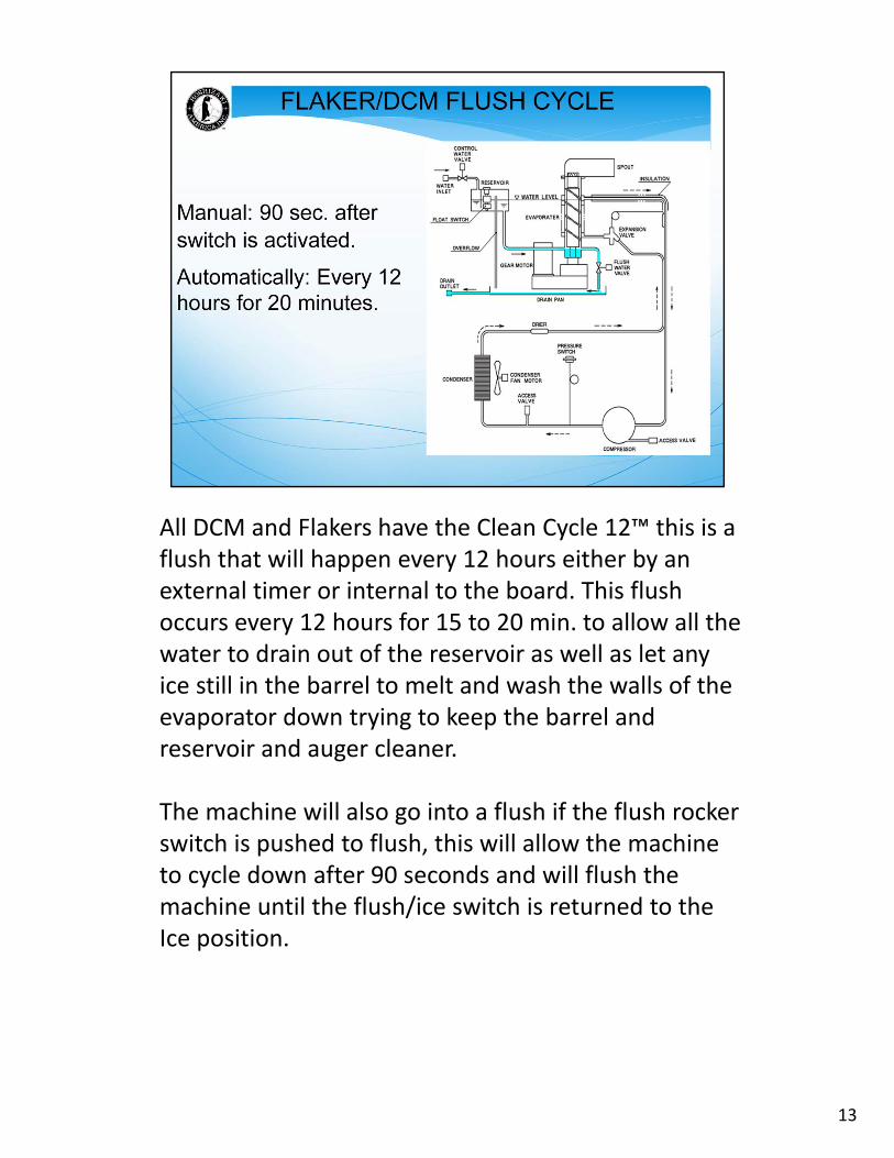
All DCM and Flakers have the Clean Cycle 12™ this is a flush that will happen every 12 hours either by an external timer or internal to the board. This flush occurs every 12 hours for 15 to 20 min. to allow all the water to drain out of the reservoir as well as let any ice still in the barrel to melt and wash the walls of the evaporator down trying to keep the barrel and reservoir and auger cleaner.
The machine will also go into a flush if the flush rocker switch is pushed to flush, this will allow the machine to cycle down after 90 seconds and will flush the machine until the flush/ice switch is returned to the Ice position.
14
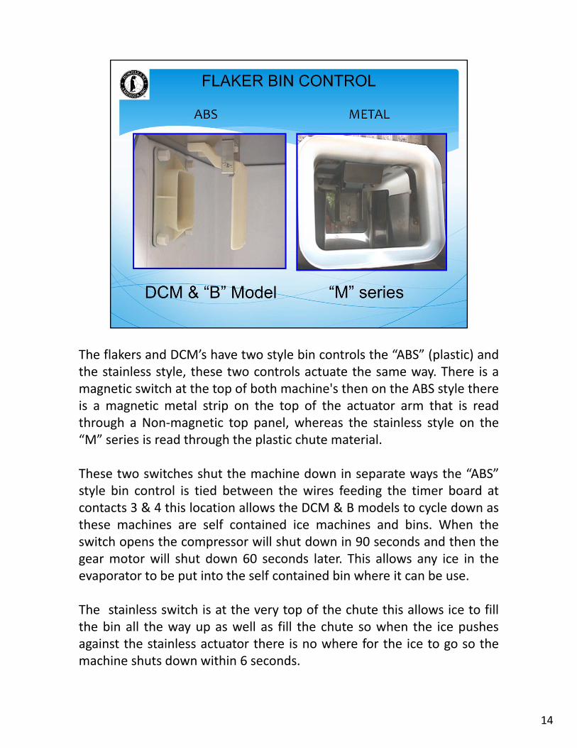
The flakers and DCM’s have two style bin controls the “ABS” (plastic) andthe stainless style, these two controls actuate the same way. There is amagnetic switch at the top of both machine's then on the ABS style thereis a magnetic metal strip on the top of the actuator arm that is readthrough a Non‐magnetic top panel, whereas the stainless style on the“M” series is read through the plastic chute material.
These two switches shut the machine down in separate ways the “ABS”style bin control is tied between the wires feeding the timer board atcontacts 3 & 4 this location allows the DCM & B models to cycle down asthese machines are self contained ice machines and bins. When theswitch opens the compressor will shut down in 90 seconds and then thegear motor will shut down 60 seconds later. This allows any ice in theevaporator to be put into the self contained bin where it can be use.
The stainless switch is at the very top of the chute this allows ice to fillthe bin all the way up as well as fill the chute so when the ice pushesagainst the stainless actuator there is no where for the ice to go so themachine shuts down within 6 seconds.
15
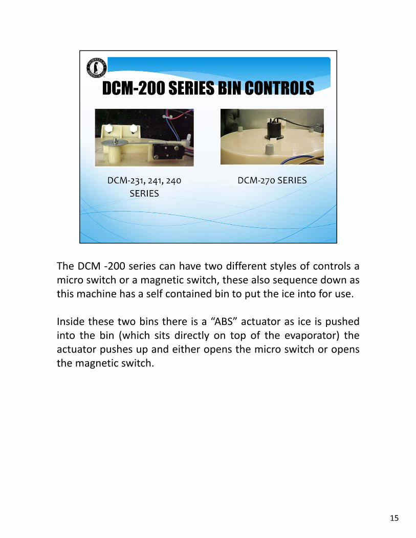
The DCM ‐200 series can have two different styles of controls amicro switch or a magnetic switch, these also sequence down asthis machine has a self contained bin to put the ice into for use.
Inside these two bins there is a “ABS” actuator as ice is pushedinto the bin (which sits directly on top of the evaporator) theactuator pushes up and either opens the micro switch or opensthe magnetic switch.
16
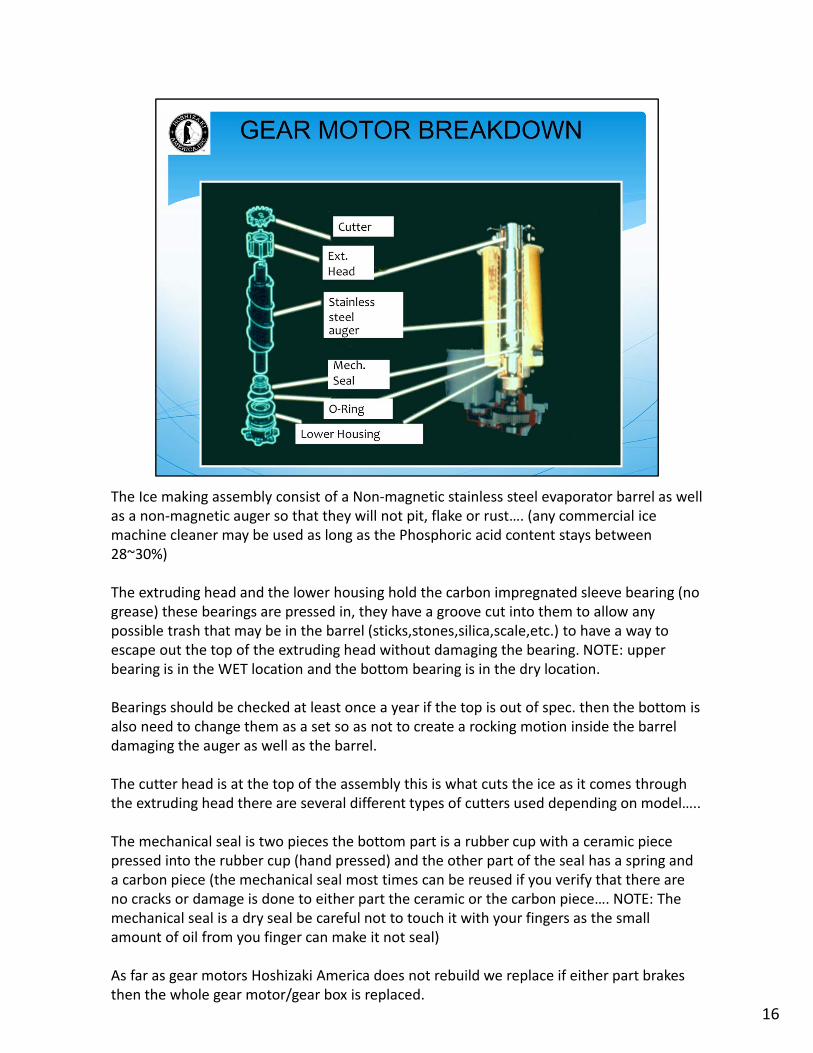
The Ice making assembly consist of a Non‐magnetic stainless steel evaporator barrel as well as a non‐magnetic auger so that they will not pit, flake or rust…. (any commercial ice machine cleaner may be used as long as the Phosphoric acid content stays between 28~30%)
The extruding head and the lower housing hold the carbon impregnated sleeve bearing (no grease) these bearings are pressed in, they have a groove cut into them to allow any possible trash that may be in the barrel (sticks,stones,silica,scale,etc.) to have a way to escape out the top of the extruding head without damaging the bearing. NOTE: upper bearing is in the WET location and the bottom bearing is in the dry location.
Bearings should be checked at least once a year if the top is out of spec. then the bottom is also need to change them as a set so as not to create a rocking motion inside the barrel damaging the auger as well as the barrel.
The cutter head is at the top of the assembly this is what cuts the ice as it comes through the extruding head there are several different types of cutters used depending on model…..
The mechanical seal is two pieces the bottom part is a rubber cup with a ceramic piece pressed into the rubber cup (hand pressed) and the other part of the seal has a spring and a carbon piece (the mechanical seal most times can be reused if you verify that there are no cracks or damage is done to either part the ceramic or the carbon piece…. NOTE: The mechanical seal is a dry seal be careful not to touch it with your fingers as the small amount of oil from you finger can make it not seal)
As far as gear motors Hoshizaki America does not rebuild we replace if either part brakes then the whole gear motor/gear box is replaced.
17
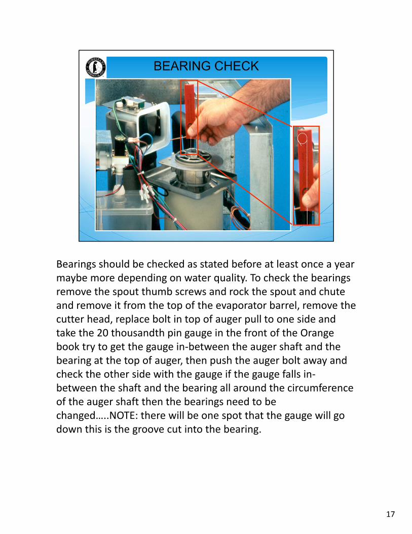
Bearings should be checked as stated before at least once a year maybe more depending on water quality. To check the bearings remove the spout thumb screws and rock the spout and chute and remove it from the top of the evaporator barrel, remove the cutter head, replace bolt in top of auger pull to one side and take the 20 thousandth pin gauge in the front of the Orange book try to get the gauge in‐between the auger shaft and the bearing at the top of auger, then push the auger bolt away and check the other side with the gauge if the gauge falls in‐between the shaft and the bearing all around the circumference of the auger shaft then the bearings need to be changed…..NOTE: there will be one spot that the gauge will go down this is the groove cut into the bearing.
18
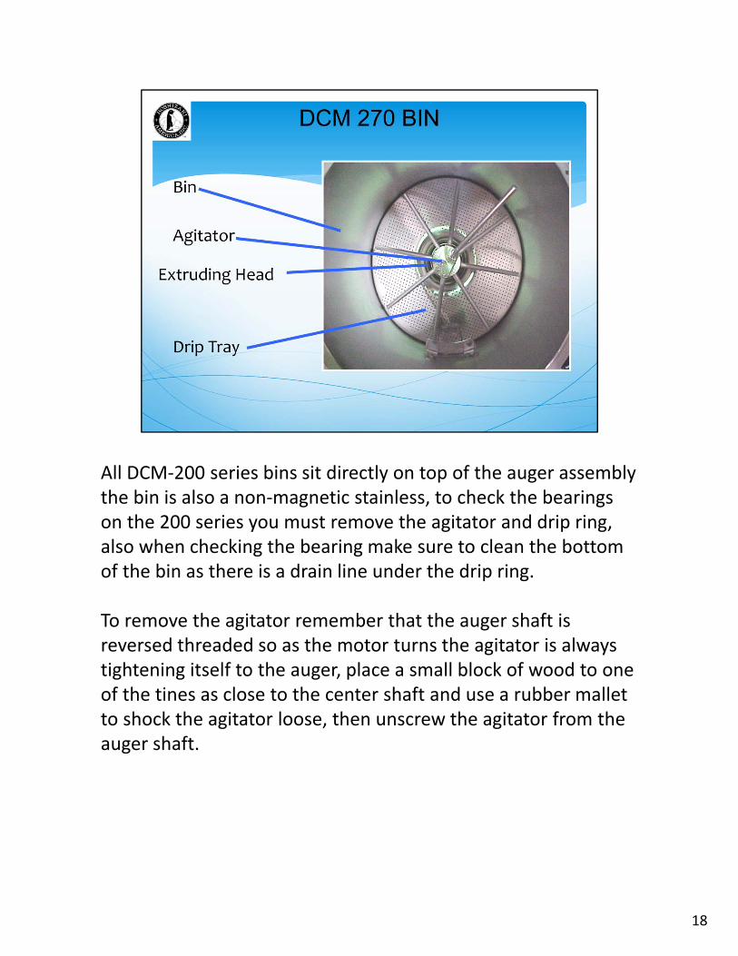
All DCM‐200 series bins sit directly on top of the auger assembly the bin is also a non‐magnetic stainless, to check the bearings on the 200 series you must remove the agitator and drip ring, also when checking the bearing make sure to clean the bottom of the bin as there is a drain line under the drip ring.
To remove the agitator remember that the auger shaft is reversed threaded so as the motor turns the agitator is always tightening itself to the auger, place a small block of wood to one of the tines as close to the center shaft and use a rubber mallet to shock the agitator loose, then unscrew the agitator from the auger shaft.
19
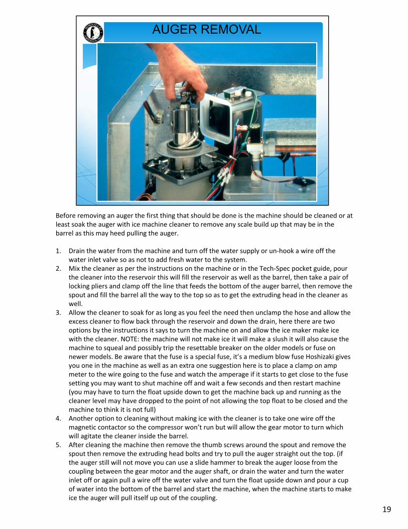
Before removing an auger the first thing that should be done is the machine should be cleaned or at least soak the auger with ice machine cleaner to remove any scale build up that may be in the barrel as this may heed pulling the auger.
1. Drain the water from the machine and turn off the water supply or un‐hook a wire off the water inlet valve so as not to add fresh water to the system.
2. Mix the cleaner as per the instructions on the machine or in the Tech‐Spec pocket guide, pour the cleaner into the reservoir this will fill the reservoir as well as the barrel, then take a pair of locking pliers and clamp off the line that feeds the bottom of the auger barrel, then remove the spout and fill the barrel all the way to the top so as to get the extruding head in the cleaner as well.
3. Allow the cleaner to soak for as long as you feel the need then unclamp the hose and allow the excess cleaner to flow back through the reservoir and down the drain, here there are two options by the instructions it says to turn the machine on and allow the ice maker make ice with the cleaner. NOTE: the machine will not make ice it will make a slush it will also cause the machine to squeal and possibly trip the resettable breaker on the older models or fuse on newer models. Be aware that the fuse is a special fuse, it’s a medium blow fuse Hoshizaki gives you one in the machine as well as an extra one suggestion here is to place a clamp on amp meter to the wire going to the fuse and watch the amperage if it starts to get close to the fuse setting you may want to shut machine off and wait a few seconds and then restart machine (you may have to turn the float upside down to get the machine back up and running as the cleaner level may have dropped to the point of not allowing the top float to be closed and the machine to think it is not full)
4. Another option to cleaning without making ice with the cleaner is to take one wire off the magnetic contactor so the compressor won’t run but will allow the gear motor to turn which will agitate the cleaner inside the barrel.
5. After cleaning the machine then remove the thumb screws around the spout and remove the spout then remove the extruding head bolts and try to pull the auger straight out the top. (if the auger still will not move you can use a slide hammer to break the auger loose from the coupling between the gear motor and the auger shaft, or drain the water and turn the water inlet off or again pull a wire off the water valve and turn the float upside down and pour a cup of water into the bottom of the barrel and start the machine, when the machine starts to make ice the auger will pull itself up out of the coupling.
20