Embed Size (px)
Citation preview

THE FIRE ZONEand The Insurance Zone ®
© Copyright 2013The CAD Zone, Inc. - Beaverton, OR
All Rights Reserved

The Fire Zone - Page 2 Welcome
Welcome to The Fire Zone and
The Insurance Zone!
This chapter introduces you to the Fire Zone™ and Insur-ance Zone® drawing programs. It explains how to get help with the program, and includes a basic tutorial designed to get you drawing fast.
Throughout this manual you will see reference to “the Diagram Program.” This is because the information in this manual applies to multiple drawing programs published by The CAD Zone, Inc. If you are using either The Fire Zone or The Insurance Zone, this manual is for you:
The Fire ZoneThe Insurance Zone
How To Contact UsFreel free to contact The CAD Zone with any questions:
The CAD Zone web site at: http://www.cadzone.com Email support: [email protected]
Phone Support: (503) 641-0334 (Monday-Friday, 7:30 a.m. - 5:00 p.m. PST) FAX: (503) 641-9077
The Fire Zone is a trademark of The CAD Zone, Inc.The Insurance Zone is a registered trademark of The CAD Zone, Inc.AutoCAD® is a registered trademark of Autodesk, Inc.Adobe® Acrobat® is a registered trademark of Adobe Systems, Inc.Bing™ is a trademark of Microsoft Corporation
The Fire Zone - Page 3 System Requirements
CompatibilityWith The CAD Zone’s Diagram Programs you can import draw-ings from most other CAD programs including AutoCAD®, AutoSketch®, Generic CADD®, and previous versions of The Fire Zone and The Insurance Zone - all with no conversion! Also, the Diagram Program will allow you to save to .BMP, .WMF, and .JPEG formats for easy placement into text documents!
System RequirementsTo use The Fire Zone or The Insurance Zone, you must have a computer with a Pentium IV or better central processor, running Microsoft Windows XP, Windows Vista, or Windows 7. You must have at least 512 MB of RAM (1 GB, or more is recommended) and 1 GB of free hard disk space. The minimum screen resolu-tion is 1024 x 768 pixels.
Do you have mobile computersin your apparatus?
Turn to the back of this manual to learn more about using First Look Pro on your
mobile computers!
The Fire Zone - Page 4 Copyright laws apply
Copyright Laws Apply!All CAD Zone software is protected by international copy-right laws. You probably know you can’t legally make a copy of someone’s book (if it is protected by a copyright) and give it to everyone in your department or company. The same protection applies to software. When you purchase a copy of The Fire Zone or The Insurance Zone, you are actually purchasing a license to use the program on ONE COMPUTER.
Each purchased copy of the software may be installed only on a single computer.
This means you can obtain one Access Key, which allows you to license the software on one computer for each copy of the software you purchase. The CAD Zone’s complete License Agree-ment is printed on the envelope that contains your program CD.
Install First - Then License Your SoftwareSeparate Installation instructions are included in this software package. Follow those instructions to install your program.You can only license your program AFTER IT IS INSTALLED onto your computer.
When you first install the program, it will be in Evaluation Mode. This means you can open the program 10 times and have access to all of the program features. After those 10 times you can still open the program and try it out, but you will not be able to save your diagrams until you complete the licensing of your new soft-ware. To license your program for unlimited use, you must obtain an Access Key from The CAD Zone and enter it into the program.
The Access Key is unique to each computer. You can and call, email, or go online to receive your Access Key.
Before you can obtain an Access Key, you must purchase the program. The CAD Zone must have received a Purchase Order from your government agency or have successfully charged your credit card.
The Fire Zone - Page 5 How to obtain an Access Key
Ways To Obtain an Access KeyEach time you open the program, a Registration dialog box is displayed that prompts you to enter an Access Key. You can also bring up this dialog box at any time with these steps:
1. Open the program and select the Help pull-down menu.2. Select License.
Once the Registration dialog box is displayed, you will see the Computer ID for your computer. You must provide this Comput-er ID to The CAD Zone so we can generate your unique Access Key. This Access Key will ONLY work on the computer with the matching Computer ID. Once you enter your Access Key, your program will be fully licensed and you will have unlimited access to all the program’s features.
To License Your Software Online: When you purchase your software you will receive an email notice with information on how to log onto the CAD Zone web site and obtain your access key.
1. As instructed in the email, go to http://www.cadzone.com/license and log in to the customer account that has been set up for you. The email will contain the user name and temporary password.
2. Once you log in, you will be sent to the “Get Keys” web page. Choose the product you wish to license and enter the particular computer’s ID (described above).
3. Follow the instructions on the site to obtain your Access Key and enter it into the Registration dialog box in the program (described above).
To License Your Software Via Email:1. Open the program and bring up the Registration dialog
box, as described above.2. Click the button “Get Access Key Via Email.”3. Enter your customer information in the form that is
displayed.4. Click “Submit Email request for Access Key.” Your Access
Key will be emailed, normally on the next business day.
The Fire Zone - Page 6 How to get help
To License Your Software by Phone:1. Open the program and bring up the Registration dialog
box, as described above.2. Call The CAD Zone at 800-641-9077 and give us your
Computer ID. 3. We’ll generate your Access Key and read it back to you
over the phone so you can enter it into the Registration dialog box.
Phone registration is accepted Monday through Friday, 7:30 am to 5:00 pm Pacific Time.
Once you enter a correct Access Key, you should receive a message that says the program was successfully licensed.
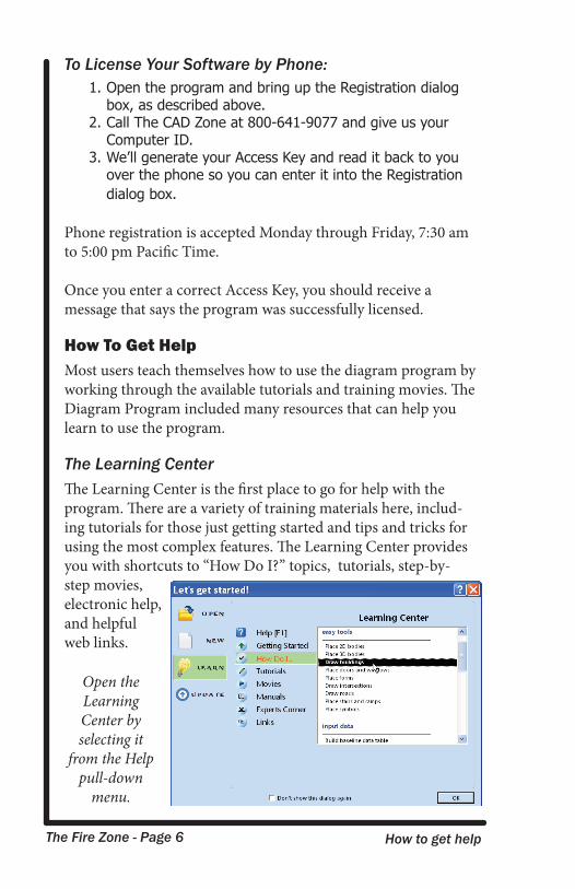
How To Get HelpMost users teach themselves how to use the diagram program by working through the available tutorials and training movies. The Diagram Program included many resources that can help you learn to use the program.
The Learning CenterThe Learning Center is the first place to go for help with the program. There are a variety of training materials here, includ-ing tutorials for those just getting started and tips and tricks for using the most complex features. The Learning Center provides you with shortcuts to “How Do I?” topics, tutorials, step-by-step movies, electronic help, and helpful web links.
Open the Learning Center by selecting it
from the Help pull-down
menu.
The Fire Zone - Page 7 Help and training resources
Electronic HelpThe electronic help (accessed from the Help pull-down menu), contains step-by-step instructions for commands used in the program and instructional tutorials. Help topics for the various command toolboxes can also be accessed by clicking the question mark icon (?) located at the top-right of each toolbox.
The Learning Center MoviesA separate Learning Center Movies CD-Rom (or DVD) is included with the software. The Movies CD contains step-by-step instructional movies for most of the commands used in the program.
If you look at the bottom of the left-hand toolbox, you will see orange arrow buttons beside each category. Clicking them brings up a menu of movies you can view.
If you do not have access to the Movies CD, the training movies can also be viewed from the training section of The CAD Zone’s web site.
CAD Zone Training Web SiteThe CAD Zone’s training web site contains tutorials, command reference manuals, training movies, and other User Documenta-tion. To enter The CAD Zone’s training web site:
1. Go to: www.cadzone.com and select the Training button2. Or go directly to: http://training.cadzone.com
Free Technical SupportThe CAD Zone offers free telephone and email technical support. You can receive Email support by submitting your questions to: [email protected] Telephone support is available by calling:
(503) 641-0334, Monday-Friday 8 a.m. - 4:30 p.m. Pacific Time.
The Fire Zone - Page 8 Drawing basics
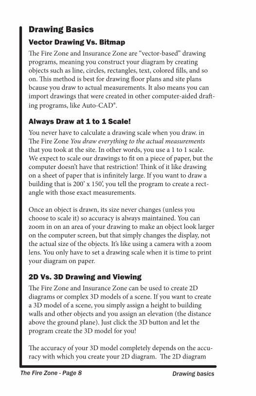
Drawing BasicsVector Drawing Vs. BitmapThe Fire Zone and Insurance Zone are “vector-based” drawing programs, meaning you construct your diagram by creating objects such as line, circles, rectangles, text, colored fills, and so on. This method is best for drawing floor plans and site plans bcause you draw to actual measurements. It also means you can import drawings that were created in other computer-aided draft-ing programs, like Auto-CAD®.
Always Draw at 1 to 1 Scale!You never have to calculate a drawing scale when you draw. in The Fire Zone You draw everything to the actual measurements that you took at the site. In other words, you use a 1 to 1 scale. We expect to scale our drawings to fit on a piece of paper, but the computer doesn’t have that restriction! Think of it like drawing on a sheet of paper that is infinitely large. If you want to draw a building that is 200’ x 150’, you tell the program to create a rect-angle with those exact measurements.
Once an object is drawn, its size never changes (unless you choose to scale it) so accuracy is always maintained. You can zoom in on an area of your drawing to make an object look larger on the computer screen, but that simply changes the display, not the actual size of the objects. It’s like using a camera with a zoom lens. You only have to set a drawing scale when it is time to print your diagram on paper.
2D Vs. 3D Drawing and ViewingThe Fire Zone and Insurance Zone can be used to create 2D diagrams or complex 3D models of a scene. If you want to create a 3D model of a scene, you simply assign a height to building walls and other objects and you assign an elevation (the distance above the ground plane). Just click the 3D button and let the program create the 3D model for you!
The accuracy of your 3D model completely depends on the accu-racy with which you create your 2D diagram. The 2D diagram
The Fire Zone - Page 9 The program screen
has to come first. For this reason, this manual will be dedicated to introducing the tools you need to draw in 2D. There are a variety of movies and electronic help topics on using the program’s 3D features, to which you can refer when you’re ready for 3D.
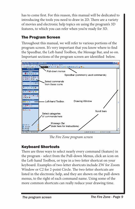
The Program ScreenThroughout this manual, we will refer to various portions of the program screen. It’s very important that you know where to find the Speedbar, the Left-hand Toolbox, the Message Bar, and so on. Important sections of the program screen are identified below.
Keyboard ShortcutsThere are three ways to select nearly every command (feature) in the program - select from the Pull-down Menus, click an icon on the Left-hand Toolbox, or type in a two-letter shortcut on your keyboard. Examples of two-letter shortcuts include ZW for Zoom Window or C2 for 2-point Circle. The two-letter shortcuts are listed in the electronic help, and they are shown on the pull-down menus, to the right of each command name. Using some of the more common shortcuts can really reduce your drawing time.
The Fire Zone program screen
The Fire Zone - Page 10 Quick Start Tutorial
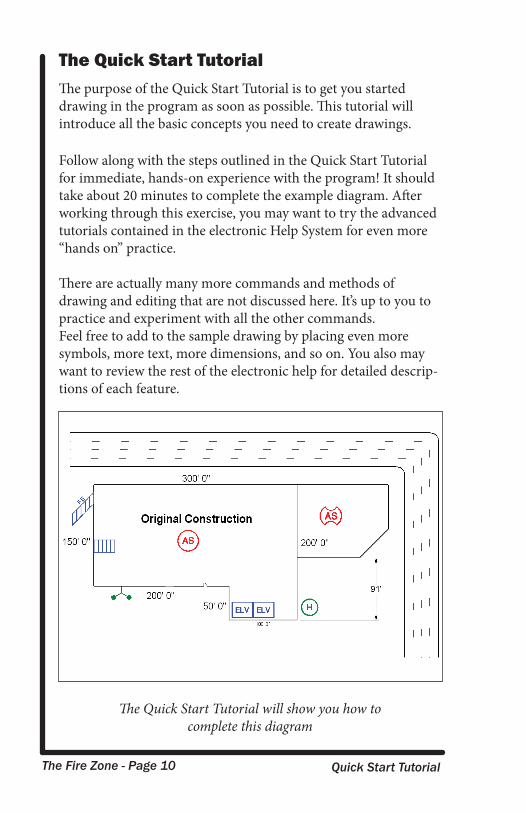
The Quick Start TutorialThe purpose of the Quick Start Tutorial is to get you started drawing in the program as soon as possible. This tutorial will introduce all the basic concepts you need to create drawings. Follow along with the steps outlined in the Quick Start Tutorial for immediate, hands-on experience with the program! It should take about 20 minutes to complete the example diagram. After working through this exercise, you may want to try the advanced tutorials contained in the electronic Help System for even more “hands on” practice.
There are actually many more commands and methods of drawing and editing that are not discussed here. It’s up to you to practice and experiment with all the other commands.Feel free to add to the sample drawing by placing even more symbols, more text, more dimensions, and so on. You also may want to review the rest of the electronic help for detailed descrip-tions of each feature.
The Quick Start Tutorial will show you how to complete this diagram
The Fire Zone - Page 11 Starting the diagram
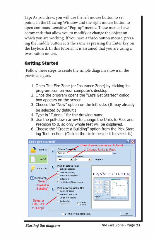
Tip: As you draw, you will use the left mouse button to set points in the Drawing Window and the right mouse button to open command sensitive “Pop-up” menus. These menus have commands that allow you to modify or change the object on which you are working. If you have a three-button mouse, press-ing the middle button acts the same as pressing the Enter key on the keyboard. In this tutorial, it is assumed that you are using a two-button mouse.
Getting Started Follow these steps to create the simple diagram shown in the previous figure.
1. Open The Fire Zone (or Insurance Zone) by clicking its program icon on your computer’s desktop.
2. Once the program opens the “Let’s Get Started” dialog box appears on the screen.
3. Choose the “New” option on the left side. (It may already be selected by default.)
4. Type in “Tutorial” for the drawing name.5. Use the pull-down arrow to change the Units to Feet and
Precision to 0, so only whole feet will be displayed.6. Choose the “Create a Building” option from the Pick Start-
ing Tool section. (Click in the circle beside it to select it.)
The Fire Zone - Page 12 Drawing the building with Easy Builder
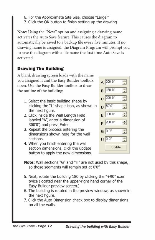
6. For the Approximate Site Size, choose “Large.”7. Click the OK button to finish setting up the drawing.
Note: Using the “New” option and assigning a drawing name activates the Auto Save feature. This causes the diagram to automatically be saved to a backup file every five minutes. If no drawing name is assigned, the Diagram Program will prompt you to save the diagram with a file name the first time Auto Save is activated.
Drawing The BuildingA blank drawing screen loads with the name you assigned it and the Easy Builder toolbox open. Use the Easy Builder toolbox to draw the outline of the building:
1. Select the basic building shape by clicking the “L” shape icon, as shown in the next figure.
2. Click inside the Wall Length Field labeled “A”, enter a dimension of 300’0”, and press Enter.
3. Repeat the process entering the dimensions shown here for the wall sections.
4. When you finish entering the wall section dimensions, click the update button to apply the new dimensions.
Note: Wall sections “G” and “H” are not used by this shape, so those segments will remain set at 0’0”.
5. Next, rotate the building 180 by clicking the “+90” icon twice (located near the upper-right hand corner of the Easy Builder preview screen.)
6. The building is rotated in the preview window, as shown in the next figure.
7. Click the Auto Dimension check box to display dimensions on all the walls.
Zooming out to change the view The Fire Zone - Page 13
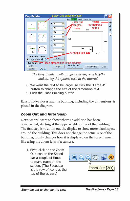
8. We want the text to be larger, so click the “Large A” button to change the size of the dimension text.
9. Click the Place Building button.
Easy Builder closes and the building, including the dimensions, is placed in the diagram.
Zoom Out and Auto SnapNext, we will want to show where an addition has been constructed, starting at the upper-right corner of the building. The first step is to zoom out the display to show more blank space around the building. This does not change the actual size of the building, it only changes how it is displayed on the screen, much like using the zoom lens of a camera.
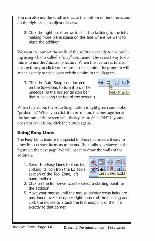
1. First, click on the Zoom Out icon on the Speed-bar a couple of times to make room on the screen. (The Speedbar is the row of icons at the top of the screen.)
The Easy Builder toolbox, after entering wall lengths and setting the options used in the tutorial.
The Fire Zone - Page 14 Drawing the addition with Easy Lines
You can also use the scroll arrows at the bottom of the screen, and on the right side, to adjust the view.
2. Click the right scroll arrow to shift the building to the left, making more blank space on the side where we want to place the addition.
We want to connect the walls of the addition exactly to the build-ing using what is called a “snap” command. The easiest way to do this is to use the Auto Snap feature. When this feature is turned on, anytime you click your mouse to set a point, the program will attach exactly to the closest existing point in the diagram.
3. Click the Auto Snap icon, located on the Speedbar, to turn it on. (The Speedbar is the horizontal icon bar that runs along the top of the screen.)
When turned on, the Auto Snap button is light green and looks “pushed in.” When you click it to turn it on, the message bar at the bottom of the screen will display “Auto Snap ON”. If yours does not say it is on, click the button again.
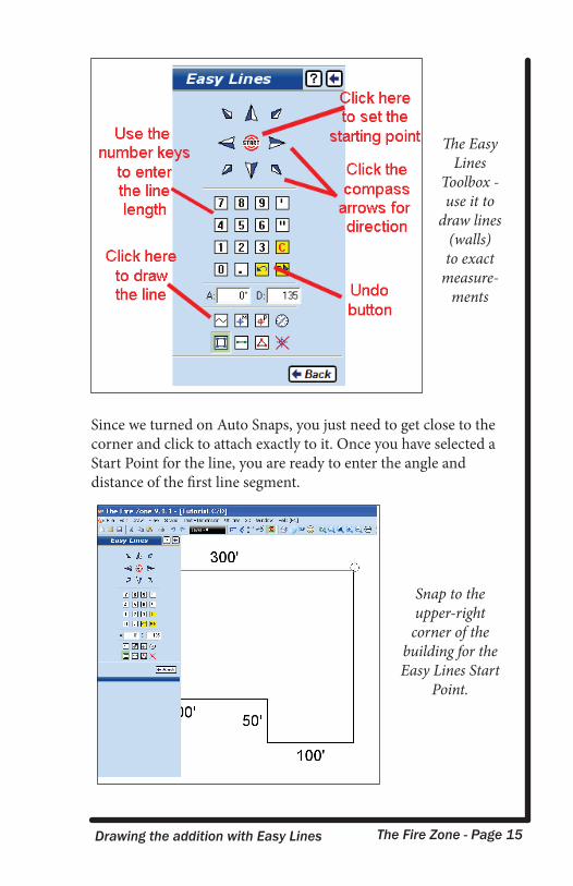
Using Easy LinesThe Easy Lines feature is a special toolbox that makes it easy to draw lines at specific measurements. The toolbox is shown in the figure on the next page. We will use it to draw the walls of the addition.
1. Select the Easy Lines toolbox by clicking its icon fron the EZ Tools section of the Tool Zone, left-hand toolbox.
2. Click on the Bull’s-eye Icon to select a starting point for the addition.
5. Move your mouse until the mouse pointer cross hairs are positioned over the upper-right corner of the building and click the mouse to attach the first endpoint of the line exactly to that corner.
The Fire Zone - Page 15 Drawing the addition with Easy Lines
Since we turned on Auto Snaps, you just need to get close to the corner and click to attach exactly to it. Once you have selected a Start Point for the line, you are ready to enter the angle and distance of the first line segment.
The EasyLines
Toolbox - use it to
draw lines (walls) to exact
measure-ments
Snap to the upper-right
corner of the building for the Easy Lines Start
Point.
The Fire Zone - Page 16 Drawing the addition with Easy Lines
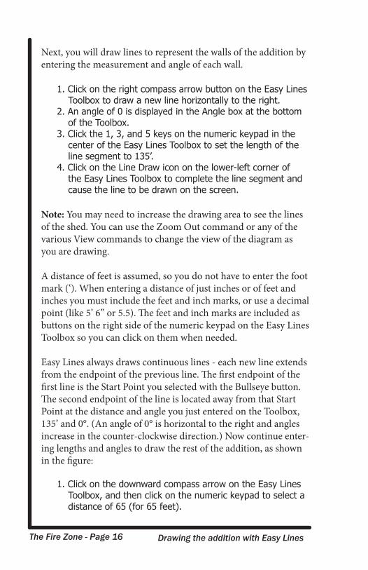
Next, you will draw lines to represent the walls of the addition by entering the measurement and angle of each wall.
1. Click on the right compass arrow button on the Easy Lines Toolbox to draw a new line horizontally to the right.
2. An angle of 0 is displayed in the Angle box at the bottom of the Toolbox.
3. Click the 1, 3, and 5 keys on the numeric keypad in the center of the Easy Lines Toolbox to set the length of the line segment to 135’.
4. Click on the Line Draw icon on the lower-left corner of the Easy Lines Toolbox to complete the line segment and cause the line to be drawn on the screen.
Note: You may need to increase the drawing area to see the lines of the shed. You can use the Zoom Out command or any of the various View commands to change the view of the diagram as you are drawing.
A distance of feet is assumed, so you do not have to enter the foot mark (‘). When entering a distance of just inches or of feet and inches you must include the feet and inch marks, or use a decimal point (like 5’ 6” or 5.5). The feet and inch marks are included as buttons on the right side of the numeric keypad on the Easy Lines Toolbox so you can click on them when needed.
Easy Lines always draws continuous lines - each new line extends from the endpoint of the previous line. The first endpoint of the first line is the Start Point you selected with the Bullseye button. The second endpoint of the line is located away from that Start Point at the distance and angle you just entered on the Toolbox, 135’ and 0°. (An angle of 0° is horizontal to the right and angles increase in the counter-clockwise direction.) Now continue enter-ing lengths and angles to draw the rest of the addition, as shown in the figure:
1. Click on the downward compass arrow on the Easy Lines Toolbox, and then click on the numeric keypad to select a distance of 65 (for 65 feet).
The Fire Zone - Page 17 Saving the diagram
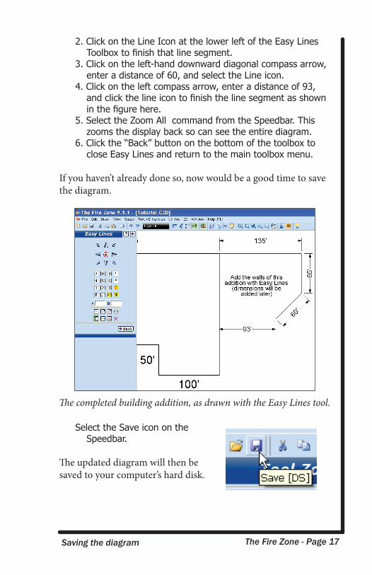
2. Click on the Line Icon at the lower left of the Easy Lines Toolbox to finish that line segment.
3. Click on the left-hand downward diagonal compass arrow, enter a distance of 60, and select the Line icon.
4. Click on the left compass arrow, enter a distance of 93, and click the line icon to finish the line segment as shown in the figure here.
5. Select the Zoom All command from the Speedbar. This zooms the display back so can see the entire diagram.
6. Click the “Back” button on the bottom of the toolbox to close Easy Lines and return to the main toolbox menu.
If you haven’t already done so, now would be a good time to save the diagram.
Select the Save icon on the Speedbar.
The updated diagram will then be saved to your computer’s hard disk.
The completed building addition, as drawn with the Easy Lines tool.
The Fire Zone - Page 18 Placing doors and windows
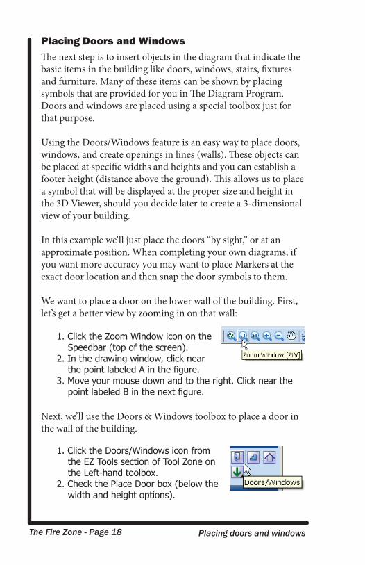
Placing Doors and WindowsThe next step is to insert objects in the diagram that indicate the basic items in the building like doors, windows, stairs, fixtures and furniture. Many of these items can be shown by placing symbols that are provided for you in The Diagram Program. Doors and windows are placed using a special toolbox just for that purpose.
Using the Doors/Windows feature is an easy way to place doors, windows, and create openings in lines (walls). These objects can be placed at specific widths and heights and you can establish a footer height (distance above the ground). This allows us to place a symbol that will be displayed at the proper size and height in the 3D Viewer, should you decide later to create a 3-dimensional view of your building.
In this example we’ll just place the doors “by sight,” or at an approximate position. When completing your own diagrams, if you want more accuracy you may want to place Markers at the exact door location and then snap the door symbols to them.
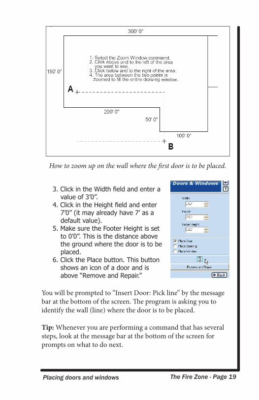
We want to place a door on the lower wall of the building. First, let’s get a better view by zooming in on that wall:
1. Click the Zoom Window icon on the Speedbar (top of the screen).
2. In the drawing window, click near the point labeled A in the figure.
3. Move your mouse down and to the right. Click near the point labeled B in the next figure.
Next, we’ll use the Doors & Windows toolbox to place a door in the wall of the building.
1. Click the Doors/Windows icon from the EZ Tools section of Tool Zone on the Left-hand toolbox.
2. Check the Place Door box (below the width and height options).
The Fire Zone - Page 19 Placing doors and windows
3. Click in the Width field and enter a value of 3’0”.
4. Click in the Height field and enter 7’0” (it may already have 7’ as a default value).
5. Make sure the Footer Height is set to 0’0”. This is the distance above the ground where the door is to be placed.
6. Click the Place button. This button shows an icon of a door and is above “Remove and Repair.”
You will be prompted to “Insert Door: Pick line” by the message bar at the bottom of the screen. The program is asking you to identify the wall (line) where the door is to be placed.
Tip: Whenever you are performing a command that has several steps, look at the message bar at the bottom of the screen for prompts on what to do next.
How to zoom up on the wall where the first door is to be placed.
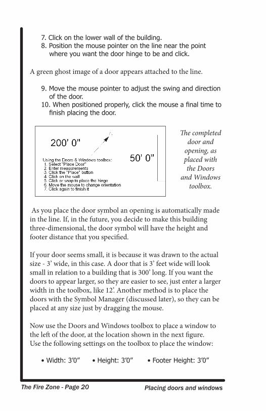
The Fire Zone - Page 20 Placing doors and windows
7. Click on the lower wall of the building.8. Position the mouse pointer on the line near the point
where you want the door hinge to be and click.
A green ghost image of a door appears attached to the line.
9. Move the mouse pointer to adjust the swing and direction of the door.
10. When positioned properly, click the mouse a final time to finish placing the door.
As you place the door symbol an opening is automatically made in the line. If, in the future, you decide to make this building three-dimensional, the door symbol will have the height and footer distance that you specified.
If your door seems small, it is because it was drawn to the actual size - 3’ wide, in this case. A door that is 3’ feet wide will look small in relation to a building that is 300’ long. If you want the doors to appear larger, so they are easier to see, just enter a larger width in the toolbox, like 12’. Another method is to place the doors with the Symbol Manager (discussed later), so they can be placed at any size just by dragging the mouse.
Now use the Doors and Windows toolbox to place a window to the left of the door, at the location shown in the next figure.Use the following settings on the toolbox to place the window:
• Width: 3’0” • Height: 3’0” • Footer Height: 3’0”
The completed door and
opening, as placed with the Doors
and Windows toolbox.
The Fire Zone - Page 21 Placing symbols
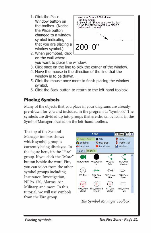
1. Click the Place Window button on the toolbox. (Notice the Place button changed to a window symbol indicating that you are placing a window symbol.)
2. When prompted, click on the wall where you want to place the window.
3. Click once on the line to pick the corner of the window.4. Move the mouse in the direction of the line that the
window is to be drawn.5. Click the mouse once more to finish placing the window
symbol.6. Click the Back button to return to the left-hand toolbox.
Placing SymbolsMany of the objects that you place in your diagrams are already pre-drawn for you and included in the program as “symbols.” The symbols are divided up into groups that are shown by icons in the Symbol Manager located on the left-hand toolbox.
The top of the Symbol Manager toolbox shows which symbol group is currently being displayed. In the figure here, it’s the “Fire” group. If you click the “More” button beside the word Fire, you can select from the other symbol groups including, Insurance, Investigation, NFPA 170, Alarms, Air Military, and more. In this tutorial, we will use symbols from the Fire group.
The Symbol Manager Toolbox
The Fire Zone - Page 22 Symbol groups
Note: If you are using a customized version of the program that was created just for your company, you may have different symbol categories and different symbols than those described here. You can substitute any symbols for the ones used here. The purpose of the tutorial is to show you how the various features of the program are performed, the exact symbols you place are not really important.
Before placing symbols, let’s adjust the view of the diagram and then bring up the Symbol Manager toolbox.
1. Type ZA on your keyboard. This is a shortcut command that performs a “Zoom All” so you can see your entire diagram.
2. Perform a Zoom Window around the left wall of the building where we will place the stairs symbol. (This was described in an earlier section of the tutorial.)
3. Click the Symbols button on the bottom of the left-hand toolbox to open the Symbol Manager.
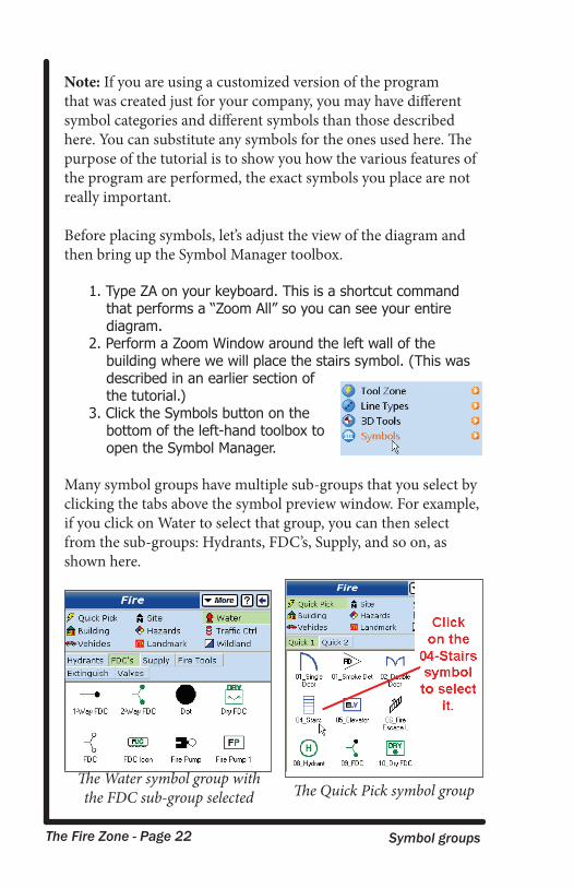
Many symbol groups have multiple sub-groups that you select by clicking the tabs above the symbol preview window. For example, if you click on Water to select that group, you can then select from the sub-groups: Hydrants, FDC’s, Supply, and so on, as shown here.
The Water symbol group with the FDC sub-group selected The Quick Pick symbol group
The Fire Zone - Page 23 Placing a stair symbol
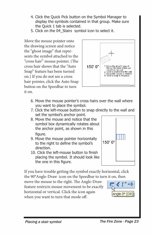
4. Click the Quick Pick button on the Symbol Manager to display the symbols contained in that group. Make sure the Quick 1 tab is selected.
5. Click on the 04_Stairs symbol icon to select it.
Move the mouse pointer onto the drawing screen and notice the “ghost image” that repre-sents the symbol attached to the “cross hair” mouse pointer. (The cross hair shows that the “Auto Snap” feature has been turned on.) If you do not see a cross hair pointer, click the Auto Snap button on the Speedbar to turn it on.
6. Move the mouse pointer’s cross hairs over the wall where you want to place the symbol.
7. Click the left-mouse button to snap directly to the wall and set the symbol’s anchor point.
8. Move the mouse and notice that the symbol box dynamically rotates about the anchor point, as shown in this figure.
9. Move the mouse pointer horizontally to the right to define the symbol’s direction.
10. Click the left-mouse button to finish placing the symbol. It should look like the one in this figure.
If you have trouble getting the symbol exactly horizontal, click the 90°Angle-Draw icon on the Speedbar to turn it on, then move the mouse to the right. The Angle-Draw feature restricts mouse movement to be exactly horizontal or vertical. Click the icon again when you want to turn that mode off.
The Fire Zone - Page 24 Placing additional symbols
Tip: If you click your mouse, but don’t like the result, press the Esc key on your keyboard to undo that click. Whenever you are performing a command, pressing Esc backs up one step. You can use Esc to undo points until you click the final time to place the symbol.
The same method is used to place all the symbols in the program. There are many other options on the Symbol Manager which you can use to mirror, explode and change the color of symbols as you place them. You should experiment with them as you place more symbols in your diagram.
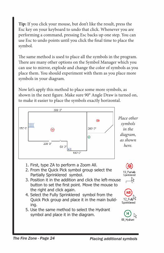
Now let’s apply this method to place some more symbols, as shown in the next figure. Make sure 90° Angle Draw is turned on, to make it easier to place the symbols exactly horizontal.
1. First, type ZA to perform a Zoom All.2. From the Quick Pick symbol group select the
Partially Sprinklered symbol.3. Position it in the addition and click the left-mouse
button to set the first point. Move the mouse to the right and click again.
4. Select the Fully Sprinklered symbol from the Quick Pick group and place it in the main build-ing.
5. Use the same method to select the Hydrant symbol and place it in the diagram.
Place other symbols in the
diagram,as shown
here.
The Fire Zone - Page 25 Moving and sizing symbols
6. Select the 05_Elevator symbol and use the same method to place it at the position shown in the figure.
Symbols are all pre-drawn to have a certain size. Depending on the size of your building, some symbols may appear too small or too large. To change the size of a symbol or other object that is already placed in your drawing, click on it to select it and use your mouse to drag the blue “handles” to the new size. You can also select multiple objects and re-size them all at once by enclos-ing them in a “Selection Window.” Refer to the Electronic Help for more information on ways to select objects.
Moving and Sizing SymbolsLet’s make the Fully Sprinklered symbol larger. Adjust your view to make it easier to see the symbol:
1. Perform a Zoom Window around the Fully Sprinklered symbol. (This command was described earlier.)
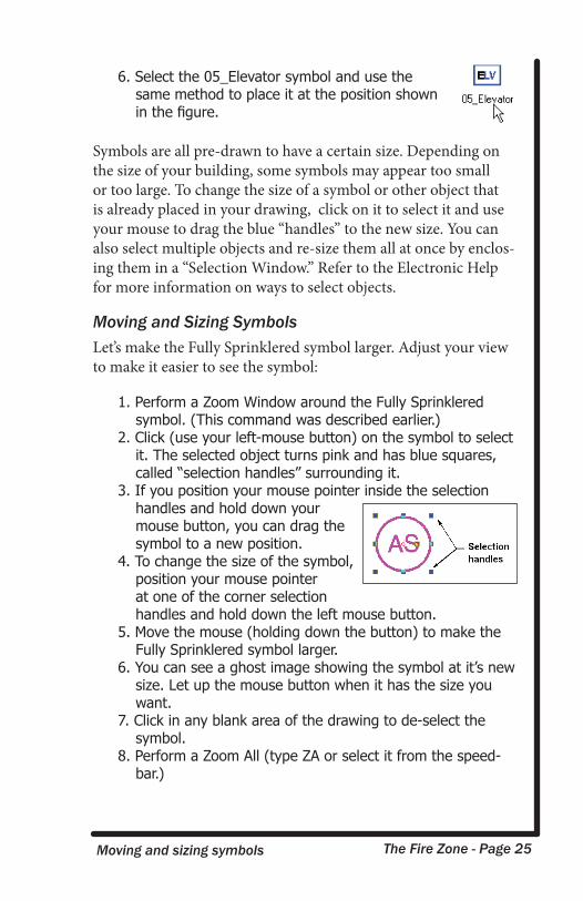
2. Click (use your left-mouse button) on the symbol to select it. The selected object turns pink and has blue squares, called “selection handles” surrounding it.
3. If you position your mouse pointer inside the selection handles and hold down your mouse button, you can drag the symbol to a new position.
4. To change the size of the symbol, position your mouse pointer at one of the corner selection handles and hold down the left mouse button.
5. Move the mouse (holding down the button) to make the Fully Sprinklered symbol larger.
6. You can see a ghost image showing the symbol at it’s new size. Let up the mouse button when it has the size you want.
7. Click in any blank area of the drawing to de-select the symbol.
8. Perform a Zoom All (type ZA or select it from the speed-bar.)
The Fire Zone - Page 26 Sizing symbols
Tip: These methods of moving and re-sizing work on all objects in your diagram, not just symbols. Remember before you can move, copy, rotate, or re-size any object, you must select them by clicking on them, or by enclosing them in a selection window.
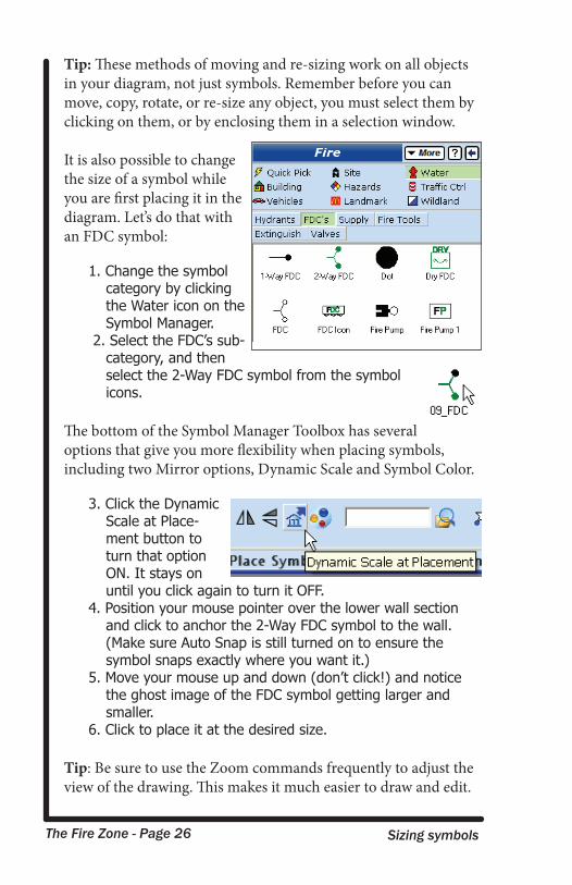
It is also possible to change the size of a symbol while you are first placing it in the diagram. Let’s do that with an FDC symbol:
1. Change the symbol category by clicking the Water icon on the Symbol Manager.
2. Select the FDC’s sub-category, and then select the 2-Way FDC symbol from the symbol icons.
The bottom of the Symbol Manager Toolbox has several options that give you more flexibility when placing symbols, including two Mirror options, Dynamic Scale and Symbol Color.
3. Click the Dynamic Scale at Place-ment button to turn that option ON. It stays on until you click again to turn it OFF.
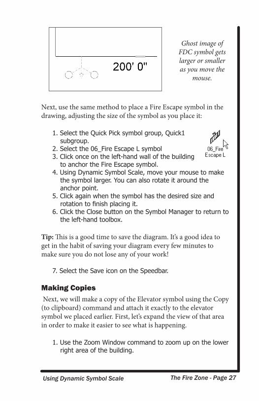
4. Position your mouse pointer over the lower wall section and click to anchor the 2-Way FDC symbol to the wall. (Make sure Auto Snap is still turned on to ensure the symbol snaps exactly where you want it.)
5. Move your mouse up and down (don’t click!) and notice the ghost image of the FDC symbol getting larger and smaller.
6. Click to place it at the desired size.
Tip: Be sure to use the Zoom commands frequently to adjust the view of the drawing. This makes it much easier to draw and edit.
The Fire Zone - Page 27 Using Dynamic Symbol Scale
Next, use the same method to place a Fire Escape symbol in the drawing, adjusting the size of the symbol as you place it:
1. Select the Quick Pick symbol group, Quick1 subgroup.
2. Select the 06_Fire Escape L symbol 3. Click once on the left-hand wall of the building
to anchor the Fire Escape symbol. 4. Using Dynamic Symbol Scale, move your mouse to make
the symbol larger. You can also rotate it around the anchor point.
5. Click again when the symbol has the desired size and rotation to finish placing it.
6. Click the Close button on the Symbol Manager to return to the left-hand toolbox.
Tip: This is a good time to save the diagram. It’s a good idea to get in the habit of saving your diagram every few minutes to make sure you do not lose any of your work!
7. Select the Save icon on the Speedbar.
Making Copies Next, we will make a copy of the Elevator symbol using the Copy (to clipboard) command and attach it exactly to the elevator symbol we placed earlier. First, let’s expand the view of that area in order to make it easier to see what is happening.
1. Use the Zoom Window command to zoom up on the lower right area of the building.
Ghost image of
FDC symbol gets larger or smaller as you move the
mouse.
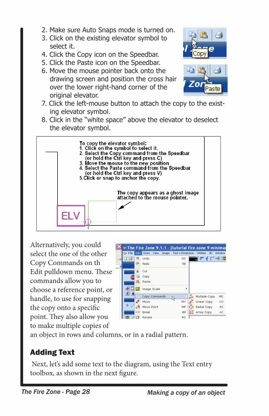
The Fire Zone - Page 28 Making a copy of an object
2. Make sure Auto Snaps mode is turned on.3. Click on the existing elevator symbol to
select it.4. Click the Copy icon on the Speedbar. 5. Click the Paste icon on the Speedbar.6. Move the mouse pointer back onto the
drawing screen and position the cross hair over the lower right-hand corner of the original elevator.
7. Click the left-mouse button to attach the copy to the exist-ing elevator symbol.
8. Click in the “white space” above the elevator to deselect the elevator symbol.
Alternatively, you could select the one of the other Copy Commands on th Edit pulldown menu. These commands allow you to choose a reference point, or handle, to use for snapping the copy onto a specific point. They also allow you to make multiple copies of an object in rows and columns, or in a radial pattern.
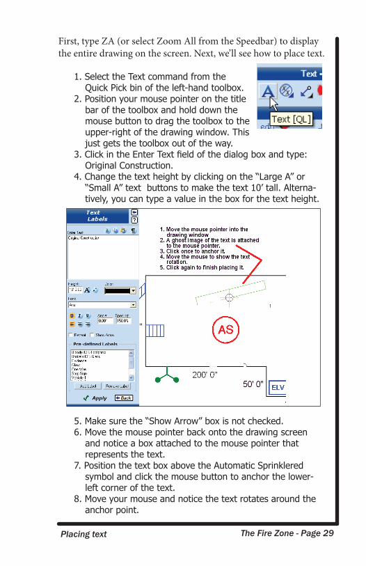
Adding Text Next, let’s add some text to the diagram, using the Text entry toolbox, as shown in the next figure.
The Fire Zone - Page 29 Placing text
First, type ZA (or select Zoom All from the Speedbar) to display the entire drawing on the screen. Next, we’ll see how to place text.
1. Select the Text command from the Quick Pick bin of the left-hand toolbox.
2. Position your mouse pointer on the title bar of the toolbox and hold down the mouse button to drag the toolbox to the upper-right of the drawing window. This just gets the toolbox out of the way.
3. Click in the Enter Text field of the dialog box and type: Original Construction.4. Change the text height by clicking on the “Large A” or
“Small A” text buttons to make the text 10’ tall. Alterna-tively, you can type a value in the box for the text height.
5. Make sure the “Show Arrow” box is not checked.6. Move the mouse pointer back onto the drawing screen
and notice a box attached to the mouse pointer that represents the text.
7. Position the text box above the Automatic Sprinklered symbol and click the mouse button to anchor the lower-left corner of the text.
8. Move your mouse and notice the text rotates around the anchor point.
The Fire Zone - Page 30 Placing dimensions
9. Move your mouse horizontally to the right and click again to finish placing the text. Turning on the 90° Angle Draw mode (if it is not already on) makes it easier to place the text exactly horizontal.
10. Following these steps, you can continue to place addi-tional text in the diagram.
11. Click Close on the Text dialog box to stop drawing text.
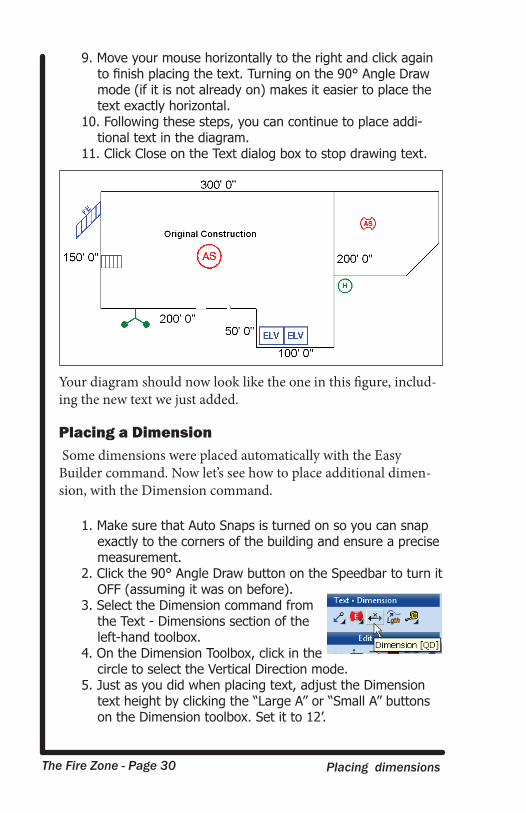
Your diagram should now look like the one in this figure, includ-ing the new text we just added.
Placing a Dimension Some dimensions were placed automatically with the Easy Builder command. Now let’s see how to place additional dimen-sion, with the Dimension command.
1. Make sure that Auto Snaps is turned on so you can snap exactly to the corners of the building and ensure a precise measurement.
2. Click the 90° Angle Draw button on the Speedbar to turn it OFF (assuming it was on before).
3. Select the Dimension command from the Text - Dimensions section of the left-hand toolbox.
4. On the Dimension Toolbox, click in the circle to select the Vertical Direction mode.
5. Just as you did when placing text, adjust the Dimension text height by clicking the “Large A” or “Small A” buttons on the Dimension toolbox. Set it to 12’.
The Fire Zone - Page 31 Placing dimensions
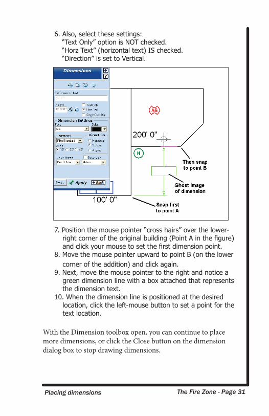
6. Also, select these settings: “Text Only” option is NOT checked.“Horz Text” (horizontal text) IS checked.“Direction” is set to Vertical.
7. Position the mouse pointer “cross hairs” over the lower-right corner of the original building (Point A in the figure) and click your mouse to set the first dimension point.
8. Move the mouse pointer upward to point B (on the lower corner of the addition) and click again.
9. Next, move the mouse pointer to the right and notice a green dimension line with a box attached that represents the dimension text.
10. When the dimension line is positioned at the desired location, click the left-mouse button to set a point for the text location.
With the Dimension toolbox open, you can continue to place more dimensions, or click the Close button on the dimension dialog box to stop drawing dimensions.
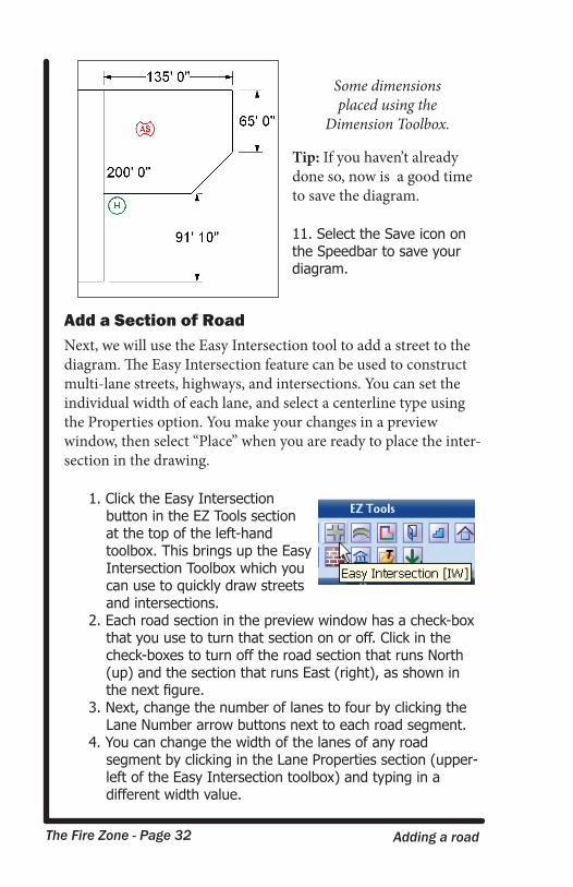
The Fire Zone - Page 32 Adding a road
Tip: If you haven’t already done so, now is a good time to save the diagram.
11. Select the Save icon on the Speedbar to save your diagram.
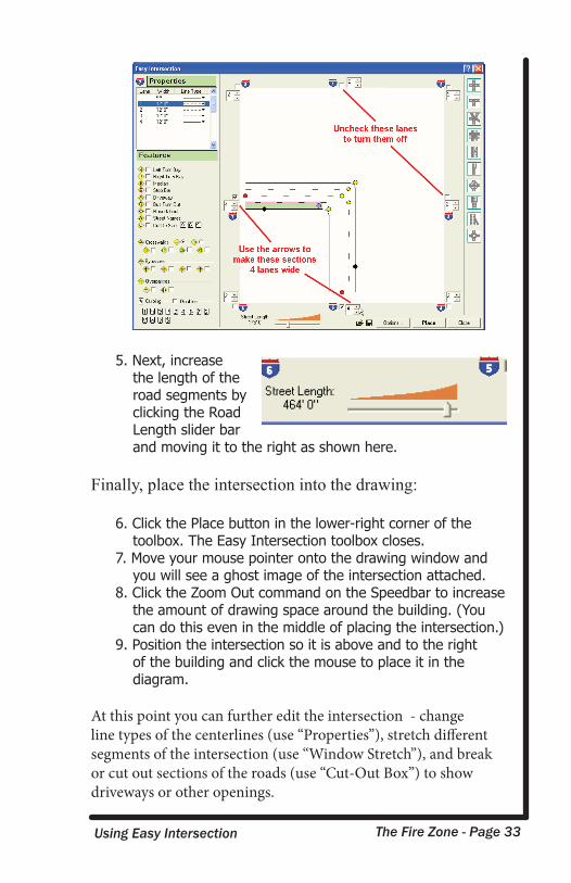
Add a Section of RoadNext, we will use the Easy Intersection tool to add a street to the diagram. The Easy Intersection feature can be used to construct multi-lane streets, highways, and intersections. You can set the individual width of each lane, and select a centerline type using the Properties option. You make your changes in a preview window, then select “Place” when you are ready to place the inter-section in the drawing.
1. Click the Easy Intersection button in the EZ Tools section at the top of the left-hand toolbox. This brings up the Easy Intersection Toolbox which you can use to quickly draw streets and intersections.
2. Each road section in the preview window has a check-box that you use to turn that section on or off. Click in the check-boxes to turn off the road section that runs North (up) and the section that runs East (right), as shown in the next figure.
3. Next, change the number of lanes to four by clicking the Lane Number arrow buttons next to each road segment.
4. You can change the width of the lanes of any road segment by clicking in the Lane Properties section (upper-left of the Easy Intersection toolbox) and typing in a different width value.
Some dimensions placed using the
Dimension Toolbox.
The Fire Zone - Page 33 Using Easy Intersection
5. Next, increase the length of the road segments by clicking the Road Length slider bar and moving it to the right as shown here.
Finally, place the intersection into the drawing:
6. Click the Place button in the lower-right corner of the toolbox. The Easy Intersection toolbox closes.
7. Move your mouse pointer onto the drawing window and you will see a ghost image of the intersection attached.
8. Click the Zoom Out command on the Speedbar to increase the amount of drawing space around the building. (You can do this even in the middle of placing the intersection.)
9. Position the intersection so it is above and to the right of the building and click the mouse to place it in the diagram.
At this point you can further edit the intersection - change line types of the centerlines (use “Properties”), stretch different segments of the intersection (use “Window Stretch”), and break or cut out sections of the roads (use “Cut-Out Box”) to show driveways or other openings.
The Fire Zone - Page 34 Printing the diagram
If you haven’t already done so, be sure to save the diagram.
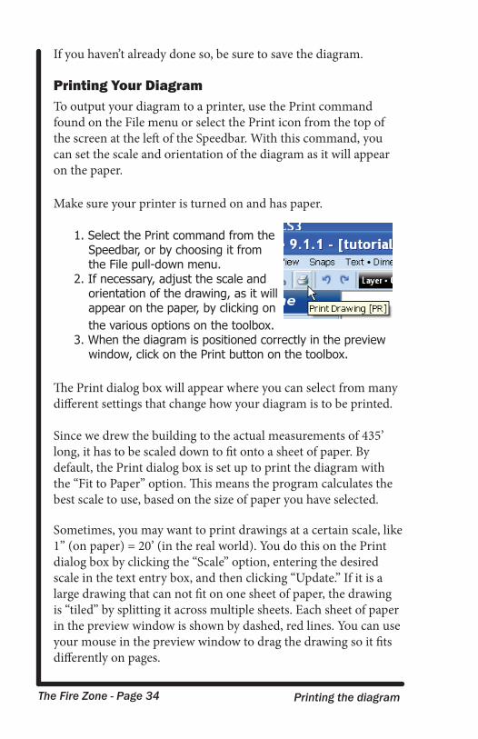
Printing Your DiagramTo output your diagram to a printer, use the Print command found on the File menu or select the Print icon from the top of the screen at the left of the Speedbar. With this command, you can set the scale and orientation of the diagram as it will appear on the paper.
Make sure your printer is turned on and has paper.
1. Select the Print command from the Speedbar, or by choosing it from the File pull-down menu.
2. If necessary, adjust the scale and orientation of the drawing, as it will appear on the paper, by clicking on the various options on the toolbox.
3. When the diagram is positioned correctly in the preview window, click on the Print button on the toolbox.
The Print dialog box will appear where you can select from many different settings that change how your diagram is to be printed.
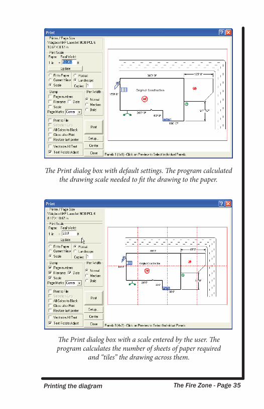
Since we drew the building to the actual measurements of 435’ long, it has to be scaled down to fit onto a sheet of paper. By default, the Print dialog box is set up to print the diagram with the “Fit to Paper” option. This means the program calculates the best scale to use, based on the size of paper you have selected.
Sometimes, you may want to print drawings at a certain scale, like 1” (on paper) = 20’ (in the real world). You do this on the Print dialog box by clicking the “Scale” option, entering the desired scale in the text entry box, and then clicking “Update.” If it is a large drawing that can not fit on one sheet of paper, the drawing is “tiled” by splitting it across multiple sheets. Each sheet of paper in the preview window is shown by dashed, red lines. You can use your mouse in the preview window to drag the drawing so it fits differently on pages.
The Fire Zone - Page 35 Printing the diagram
The Print dialog box with default settings. The program calculated the drawing scale needed to fit the drawing to the paper.
The Print dialog box with a scale entered by the user. The program calculates the number of sheets of paper required
and “tiles” the drawing across them.
The Fire Zone - Page 36 Import drawings from your City
Congratulations! You have just completed your first diagram with The Diagram Program! Now that you have a basic grasp of the program commands you should take some time to work through the advanced electronic tutorials and step-by-step movies that were installed with the program. All of the tutorials and training movies can be accessed from the Learning Center on the Help pull-down menu.
How to NOT DrawNow that you’ve seen how to draw a simple pre-incident plan, or site drawing, we’ll show you some ways to get the same result, but with very little actual drawing!
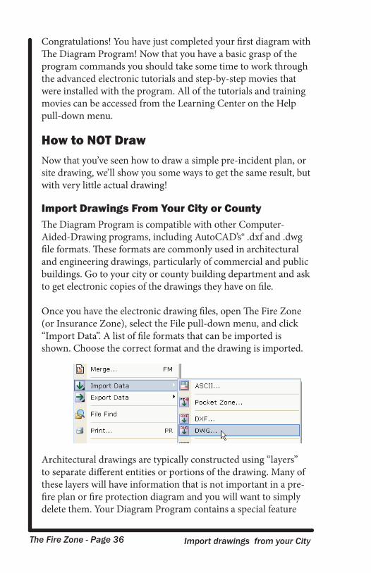
Import Drawings From Your City or CountyThe Diagram Program is compatible with other Computer-Aided-Drawing programs, including AutoCAD’s® .dxf and .dwg file formats. These formats are commonly used in architectural and engineering drawings, particularly of commercial and public buildings. Go to your city or county building department and ask to get electronic copies of the drawings they have on file.
Once you have the electronic drawing files, open The Fire Zone (or Insurance Zone), select the File pull-down menu, and click “Import Data”. A list of file formats that can be imported is shown. Choose the correct format and the drawing is imported.
Architectural drawings are typically constructed using “layers” to separate different entities or portions of the drawing. Many of these layers will have information that is not important in a pre-fire plan or fire protection diagram and you will want to simply delete them. Your Diagram Program contains a special feature
The Fire Zone - Page 37 Pre-plans from aerial photographs
called “Layer Clean-up” to help you do just that. Select the Layers icon from the Speedbar and then select Layer Cleanup from the Layer Manager.
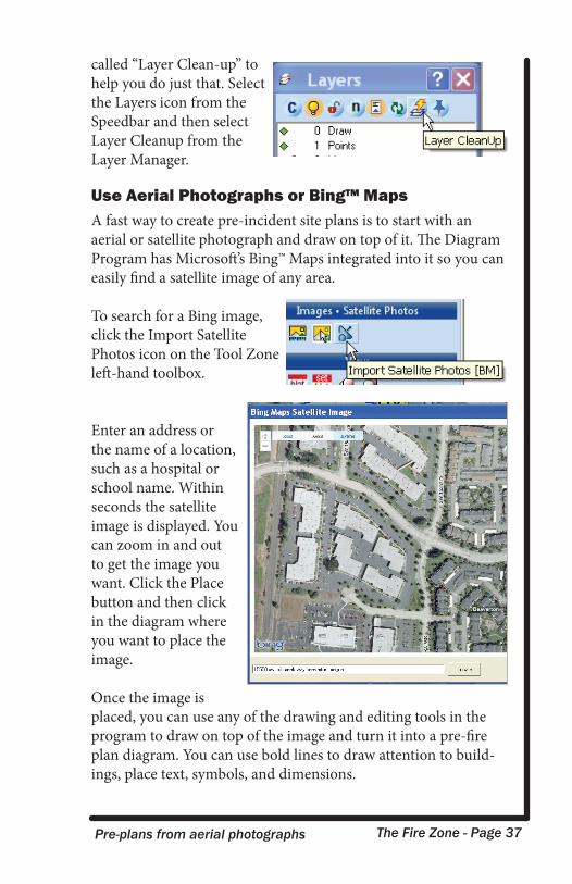
Use Aerial Photographs or Bing™ MapsA fast way to create pre-incident site plans is to start with an aerial or satellite photograph and draw on top of it. The Diagram Program has Microsoft’s Bing™ Maps integrated into it so you can easily find a satellite image of any area.
To search for a Bing image, click the Import Satellite Photos icon on the Tool Zone left-hand toolbox.
Enter an address or the name of a location, such as a hospital or school name. Within seconds the satellite image is displayed. You can zoom in and out to get the image you want. Click the Place button and then click in the diagram where you want to place the image.
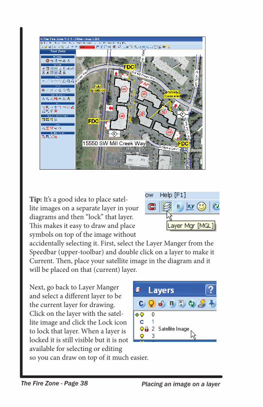
Once the image is placed, you can use any of the drawing and editing tools in the program to draw on top of the image and turn it into a pre-fire plan diagram. You can use bold lines to draw attention to build-ings, place text, symbols, and dimensions.
The Fire Zone - Page 38 Placing an image on a layer
Tip: It’s a good idea to place satel-lite images on a separate layer in your diagrams and then “lock” that layer. This makes it easy to draw and place symbols on top of the image without accidentally selecting it. First, select the Layer Manger from the Speedbar (upper-toolbar) and double click on a layer to make it Current. Then, place your satellite image in the diagram and it will be placed on that (current) layer.
Next, go back to Layer Manger and select a different layer to be the current layer for drawing. Click on the layer with the satel-lite image and click the Lock icon to lock that layer. When a layer is locked it is still visible but it is not available for selecting or editing so you can draw on top of it much easier.
The Fire Zone - Page 39 Selecting and editing diagrams
Changing Your DiagramsThe more you draw, the more you will want to make changes, or edits, to your diagrams. In the previous tutorial, we briefly discussed one way to copy and resize objects, but there are many other editing features available in the diagram program, includ-ing move, rotate, scale, trim and extend, stretch, mirror, and more.
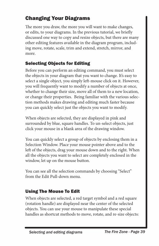
Selecting Objects for EditingBefore you can perform an editing command, you must select the objects in your diagram that you want to change. It’s easy to select a single object, you simply left-mouse click on it. However, you will frequently want to modify a number of objects at once, whether to change their size, move all of them to a new location, or change their properties. Being familiar with the various selec-tion methods makes drawing and editing much faster because you can quickly select just the objects you want to modify.
When objects are selected, they are displayed in pink and surrounded by blue, square handles. To un-select objects, just click your mouse in a blank area of the drawing window.
You can quickly select a group of objects by enclosing them in a Selection Window. Place your mouse pointer above and to the left of the objects, drag your mouse down and to the right. When all the objects you want to select are completely enclosed in the window, let up on the mouse button.
You can see all the selection commands by choosing “Select” from the Edit Pull-down menu.
Using The Mouse To EditWhen objects are selected, a red target symbol and a red square (rotation handle) are displayed near the center of the selected objects. You can use your mouse to manipulate these special handles as shortcut methods to move, rotate, and re-size objects:
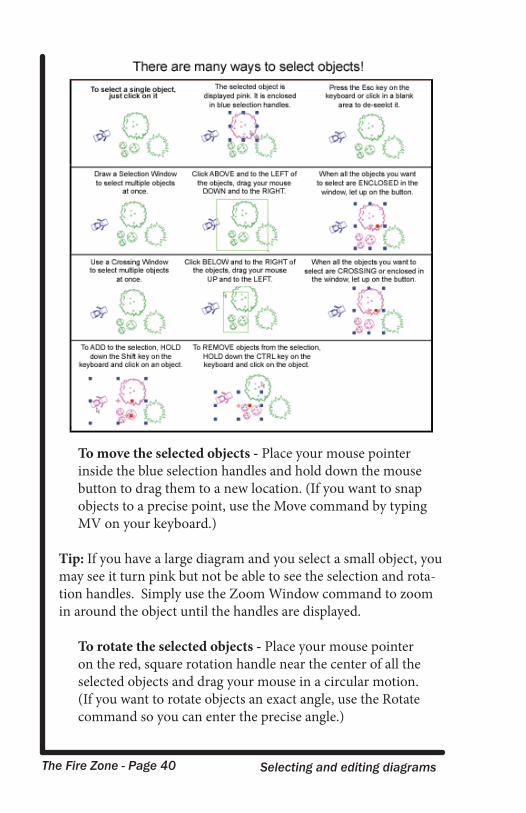
The Fire Zone - Page 40 Selecting and editing diagrams
To move the selected objects - Place your mouse pointer inside the blue selection handles and hold down the mouse button to drag them to a new location. (If you want to snap objects to a precise point, use the Move command by typing MV on your keyboard.)
Tip: If you have a large diagram and you select a small object, you may see it turn pink but not be able to see the selection and rota-tion handles. Simply use the Zoom Window command to zoom in around the object until the handles are displayed.
To rotate the selected objects - Place your mouse pointer on the red, square rotation handle near the center of all the selected objects and drag your mouse in a circular motion. (If you want to rotate objects an exact angle, use the Rotate command so you can enter the precise angle.)
The Fire Zone - Page 41 Using Editing commands
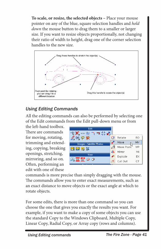
To scale, or resize, the selected objects – Place your mouse pointer on any of the blue, square selection handles and hold down the mouse button to drag them to a smaller or larger size. If you want to resize objects proportionally, not changing their ratio of width to height, drag one of the corner selection handles to the new size.
Using Editing CommandsAll the editing commands can also be performed by selecting one of the Edit commands from the Edit pull-down menu or from the left-hand toolbox. There are commands for moving, rotating, trimming and extend-ing, copying, breaking openings, stretching, mirroring, and so on. Often, performing an edit with one of these commands is more precise than simply dragging with the mouse. The commands allow you to enter exact measurements, such as an exact distance to move objects or the exact angle at which to rotate objects.
For some edits, there is more than one command so you can choose the one that gives you exactly the results you want. For example, if you want to make a copy of some objects you can use the standard Copy to the Windows Clipboard, Multiple Copy, Linear Copy, Radial Copy, or Array copy (rows and columns).
The Fire Zone - Page 42 Moving an object to an exact position
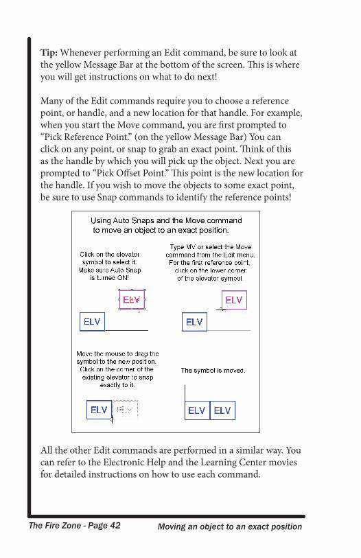
Tip: Whenever performing an Edit command, be sure to look at the yellow Message Bar at the bottom of the screen. This is where you will get instructions on what to do next!
Many of the Edit commands require you to choose a reference point, or handle, and a new location for that handle. For example, when you start the Move command, you are first prompted to “Pick Reference Point.” (on the yellow Message Bar) You can click on any point, or snap to grab an exact point. Think of this as the handle by which you will pick up the object. Next you are prompted to “Pick Offset Point.” This point is the new location for the handle. If you wish to move the objects to some exact point, be sure to use Snap commands to identify the reference points!
All the other Edit commands are performed in a similar way. You can refer to the Electronic Help and the Learning Center movies for detailed instructions on how to use each command.
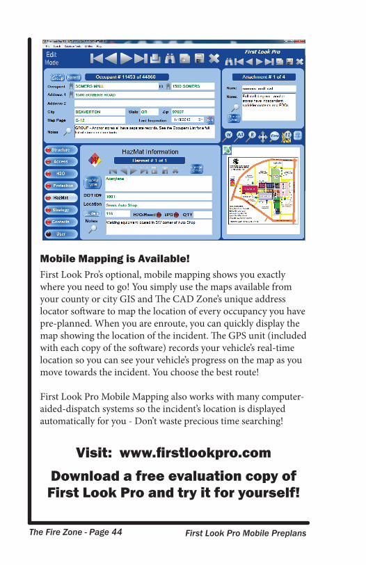
The Fire Zone - Page 43 First Look Pro Mobile Preplans
Take Your Pre-fire Plans Mobilewith First Look Pro
First Look Pro is an exciting mobile application that lets you organize and locate your Fire Zone diagrams, photographs, maps, and all your critical pre-fire plan information. With just a few keystrokes you can locate the pre-plan information for any site and preview the associated diagrams and photos. The basic infor-mation is shown on one screen and red “lights” instantly alert you where to look for information.
Always Have Your PreplansFirst Look Pro was designed to be used on mobile computers in your fire apparatus. With First Look Pro the IC can quickly size up the situation because they now have instant access to all this critical preplan information:
• Incident Location • Building Construction• Building Access • Water Supply• HazMat Information • Protection System • Contact Information • Strategy and procedure notes • Fire Zone diagrams • Maps• View attachments in most other file formats!
An intuitive user interface makes it fast and easy to enter pre-fire, hazmat, and strategy information for each site - you can enter as little or as much data as you want. No knowledge of databases or software programming is required. Once the information is entered, you can quickly retrieve, view, and modify all of your pre-fire diagrams and other preplan information.
The Fire Zone - Page 44 First Look Pro Mobile Preplans
Mobile Mapping is Available!First Look Pro’s optional, mobile mapping shows you exactly where you need to go! You simply use the maps available from your county or city GIS and The CAD Zone’s unique address locator software to map the location of every occupancy you have pre-planned. When you are enroute, you can quickly display the map showing the location of the incident. The GPS unit (included with each copy of the software) records your vehicle’s real-time location so you can see your vehicle’s progress on the map as you move towards the incident. You choose the best route!
First Look Pro Mobile Mapping also works with many computer-aided-dispatch systems so the incident’s location is displayed automatically for you - Don’t waste precious time searching!
Visit: www.firstlookpro.comDownload a free evaluation copy of First Look Pro and try it for yourself!