Embed Size (px)
Citation preview

Fire
A guide to fire alarm systems design
BS 5839 Part 1:2002
The Fire Installers Mate
CC1608_Fire Systems Design Guide_Update1_Layout 1 11/03/2010 09:56 Page 1

2
A guide to BS 5839 Part 1:2002
Disclaimer
This booklet is not intended to be acomprehensive guide to all aspects of fire alarm design but rather a very usefulsource of background information.
Whilst every care has been taken to ensurethat the contents of this document arecorrect at the time of publication, it shouldnever be used as any form of substitutionfor the BS 5839 standard itself. CooperSafety shall be under no liabilitywhatsoever in respect to such contents.
It should be noted that there may bespecific additional requirements dependentupon local authority building regulationsand/or fire authority.
Please use this guide in conjunction witha current issue of the BS 5839 standard.
CC1608_Fire Systems Design Guide_Update1_Layout 1 11/03/2010 09:56 Page 2
3
P1 P2
L1 L2L3L4
Property Protection Fire Systems
P AFD designed to primarily protect property categories:
P1 AFD installed throughout all areas
P2 AFD installed only in defined areas
Life Protection Fire Systems
L AFD designed to primarily protect human life categories:
L1 M plus AFD installed throughout all areas
L2 AFD installed in defined areas of higher risk of ignition, in addition to L3
L3 M plus AFD installed in escape routes and rooms opening into these routes
L4 M plus AFD installed in escape routes comprising circulation areas and space such as corridors and stairways
L5 A non-prescriptive system in which protected area(s) and/or the location of detectors is designed to satisfy a specific fire risk objective (other than that of L1 to L4)
M System designed to be operated manually (no AFD)
AFD - Automatic Fire Detection
Categorisation of fire alarm and detection systemsBS
583
9 Cl
ause
5
CC1608_Fire Systems Design Guide_Update1_Layout 1 11/03/2010 09:56 Page 3

4
65dB(A)@
500Hz to 1000Hz
+5dB(A)@
500Hz to 1000Hz
Bac
kgro
und
nois
e
The minimum sound level of a sounder device should be 65dB(A) or 5dB(A)above a background noise (if lasting more than 30 seconds) and at a frequencybetween 500Hz and 1000Hz. The maximum sound level should not exceed120dB(A).
Sounder device cabling should be arranged so that in the event of a fault atleast one sounder located within the vicinity of the control and indicating panelwill remain in operation.
BS 5
839
Clau
se 1
6.2.
1BS
583
9 Cl
ause
16.
2.1
CC1608_Fire Systems Design Guide_Update1_Layout 1 11/03/2010 09:56 Page 4

60m MAX
45m MAX
The maximum zone floor area should not exceed 2000m2. A person searchinga zone for a fire should not have to travel more than 60m from the zoneentrance to identify the source of the fire.
A person should not have to travel more than 45m along an escape route toreach a manual callpoint, when the layout of the building is known.
BS 5
839
Sect
ion
13.2
.3BS
583
9 Cl
ause
20.
2
5
CC1608_Fire Systems Design Guide_Update1_Layout 1 11/03/2010 09:56 Page 5

6
1.4m(+/-200mm)
2.1m
The centre of the element of the manual callpoint should be positioned 1.4m(+/-200mm) from floor level (unless a wheelchair user is likely to be the firstperson to raise the alarm, when this is applicable it should be noted on anycertification).
Visual alarms such as beacons should always be mounted at a minimum heightof 2.1m from floor level, in a position that is likely to attract attention.
BS 5
839
Clau
se 2
0.2h
BS 5
839
Clau
se 1
7
CC1608_Fire Systems Design Guide_Update1_Layout 1 11/03/2010 09:56 Page 6

2m
75dB(A)
Unless MICC or armoured cable to BS7846 standard is used, considerationshould be given to the protection against physical damage from floor level tothe height of 2m. Except in relatively benign areas, such as shops, offices andsimilar, where cabling can be clipped to robust walls.
For areas where people are sleeping, sounder devices should produce aminimum 75dB(A) at the bed-head with all doors shut. In buildings likely toprovide sleeping accommodation for the hearing impaired, considerationshould be given to the incorporation of both audio and visual devices.
BS 5
839
Clau
se 2
6.2
BS 5
839
Clau
se 1
6.2.
1
7
CC1608_Fire Systems Design Guide_Update1_Layout 1 11/03/2010 09:56 Page 7

Smoke detectors
5.3m
10.6m x 10.6m = 112m2
10.6m
7.5m
Heat detectors
3.8m
7.5m x 7.5m = 56.3m2
7.5m
5.3m
When mounted on a flat ceiling, smoke detection devices have an individualcoverage of 7.5m radius. However these radii must overlap to ensure there areno ‘blind spots’. Therefore individual coverage can be represented by a squaremeasuring 10.6 x 10.6m giving an actual coverage area of 112m2 per device.
When mounted on a flat ceiling, smoke detection devices have an individualcoverage of 5.3m radius. However these radii must overlap to ensure there areno ‘blind spots’. Therefore individual coverage can be represented by a squaremeasuring 7.5 x 7.5m giving an actual coverage area of 56.3m2 per device.
BS 5
839
Clau
se 2
2.3
BS 5
839
Clau
se 2
2.3
8
CC1608_Fire Systems Design Guide_Update1_Layout 1 11/03/2010 09:57 Page 8

In corridors less than 2m wide the horizontal spacing of detectors can beincreased, the area of coverage need not overlap as in the case of a room. Any corridor over 2m wide is deemed as a room and most adhere as specified (see page 8).
Please note: Heat detectors are not recommended for use in corridors thatmay be used as escape routes.
9
Smoke detectors15m MAX7.5m MAX
2m
BS 5
839
Clau
se 2
2.3
For ease of design and assessment of coverage dimensions used fordetectors are usually taken as:
Smoke: 5m to wall / 10m between detectorsCoverage 100m2
Heat: 3.5m to wall / 7m between detectorsCoverage 50m2
CC1608_Fire Systems Design Guide_Update1_Layout 1 11/03/2010 09:57 Page 9

10
X<1m >1m
Air vent / Air con
Decibel loss occurs through doors: Approximately -20dB(A) through a normaldoor, and approximately -30dB(A) through a fire door. Unless a sounder isinstalled in a bedroom, it is unlikely that 75dB(A) will be achieved.
Do not site detectors less than 1m from air inlets or air circulating systems.
BS 5
839
Clau
se 2
2.3
Fire
doo
r
BS 5
839
Clau
se 1
6.2.
1
CC1608_Fire Systems Design Guide_Update1_Layout 1 11/03/2010 09:57 Page 10

Apex < 150mmHeat detector
Apex < 600mmSmoke detector
Treat as a flat ceiling
Apex > 600mmSmoke detector
Apex > 150mmHeat detector
Ceiling with a apex
For ceilings that feature an apex: As long as the height of the apex fromthe rest of the ceiling is less than 150mm for heat detectors or lessthan 600mm for smoke detectors, then these can be treated the sameas flat ceilings. For higher apexes, a device should be installed at thehighest point. The distance to adjacent devices can be increased by1% per degree of angle of the roof up to a maximum of 25%.
BS 5
839
Clau
se 2
2.3
11
Detector Type Ceiling Heights (m)
General Limits Rapid Attendance*(category P systems only)
Heat Detectors EN54-5
9.0 13.57.5 12.0
Point Smoke & CO Fire Detectors 10.5 15.0
Aspirating Smoke Normal 10.5 Normal 15.0Detection Systems Enhanced 12.0 Enhanced 17.0(category 1) Very high 15.0 Very high 21.0
Optical Beam Smoke Detectors EN54-2 25.0 40.0
Class A1Other Classes
* Rapid attendance within 5 minutes
CC1608_Fire Systems Design Guide_Update1_Layout 1 11/03/2010 09:57 Page 11

12
Z x 2X
ZLight fitting/obstructuion
A device should not be mounted within 500mm of any obstruction. If the top ofa solid partition is less than 300mm from the ceiling then it should be treatedas a wall. Similary, ceiling obstructions such as beams should be treated aswalls if deeper than 10% of the ceiling height (particularly important in voids).
For obstructions less than 250mm deep never mount devices closer than twicethe depth of light fittings or other obstructions in the ceiling.
BS 5
839
Clau
se 2
2.3
Bea
m
Par
titio
n
>10%ceilingheight
<500mmX
<500mmX <300mm
BS 5
839
Clau
se 2
2.3
CC1608_Fire Systems Design Guide_Update1_Layout 1 11/03/2010 09:57 Page 12
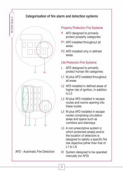
>800mm
Lift Shaft Lift Shaft
1.5m
Voids less than 800mm in height are required to have a risk assessment todetermine if AFD is required. Voids in excess of 800mm do require independentcoverage.
Vertical shafts like lift shafts and stairways should have a device mountedwithin 1.5m of any opening.
BS 5
839
Clau
se 2
2.2
BS 5
839
Clau
se 2
2.2
13
CC1608_Fire Systems Design Guide_Update1_Layout 1 11/03/2010 09:57 Page 13

14
X
102030405060708090
100
Time of day
<29°C
<4°C Maximum temperature
Average ambient temperature
XX
Tem
pera
ture
Enclosed stairways should have a detector on the top of the stairway and oneach main landing.
The minimum static response to heat devices should not be less than 29oCabove the average ambient temperature, or less than 4oC above the highesttemperature the device can be expected to experience.
BS 5
839
Clau
se 2
2.2
BS 5
839
Clau
se 3
5.2.
3
CC1608_Fire Systems Design Guide_Update1_Layout 1 11/03/2010 09:57 Page 14

Smoke detectors
Optical/Ionisation Chamber
X 25mm
600mm
X
Heat detector
Thermistor
X 25mm
150mm
X
The sensing element of a smoke detection device (optical smoke chamber)should not be less than 25mm below the ceiling, and not greater than 600mmbelow the ceiling.
The sensing element of a heat detection device should not be less than 25mmbelow the ceiling, and not greater than 150mm below the ceiling.
BS 5
839
Clau
se 2
2.3
BS 5
839
Clau
se 2
2.3
15
CC1608_Fire Systems Design Guide_Update1_Layout 1 11/03/2010 09:57 Page 15

16
Second
Ground
First
Zone 1
Zone 2
Zone 3
Zone 4
Zone 1
Zone 2
Zone 3
Zone 4
Zone 2
Zone 3
X
Less than 300m2 can be covered by a single zone. When the total floor areaexceeds 300m2, each floor would require a zone (or zones if the floor areaexceeds 2000m2) with access, stairwells or lifts covered by a zone each.
Zones should not cross floors.
BS 5
839
Clau
se 1
3.2
BS
583
9 Cl
ause
13.
2
CC1608_Fire Systems Design Guide_Update1_Layout 1 11/03/2010 09:57 Page 16

17
Mains supply
EOL fitted
EOL fitted
To comply with the current version of the BS 5839 Part 1, the use of fireresistant cables are required for all critical circuits, this includes detection,sounders and mains supply.
On a loop system, short circuit isolators are required to limit the effect of onefault to less than 2000m2 floor area. 2 simultaneous faults on a circuit shouldnot disable protection within an area greater than 10,000m2.
BS 5
839
Clau
se 2
6 BS
583
9 Cl
ause
12.
2.2
CC1608_Fire Systems Design Guide_Update1_Layout 1 11/03/2010 09:58 Page 17

18
For local isolation during maintenance, a suitable double pole isolator should be provided, suitablymarked (25.2c & f).
Cables used for all critical paths, i.e. detector, sounder and the mains supply should be wired in fireresistant cable with a minimum cross sectional area of 1 mm² (26.2j).
Enhanced fire resistant cables should be used in unsprinklered buildings where evacuation takesplace in 4 or more phases, where the building is more than 30 m in height, or the risk assessmentdeems it necessary (26.2c).
Cables require to be retained in position by a suitable fire resistant method. This requires thatshould plastic trunking be used, the cables must be clipped inside the trunking. Also plastic cableties should NOT be used (26.2f).
Control equipment should be sited in a position which is easily accessible to both staff and fire-fighters (23.2.1).
Call points are required at ALL exits to the open air and storey exits. Operation should be of asimilar type (20.2).
If multi sensors are used, if it is possible, select the operation of a particular sensor then thedetectors require to be spaced to suit the space of the lower coverage sensor i.e. a combined heat/ smoke detector, spacing would be as a heat detector (21.1.6).
All sounders in a building should have a similar sound, this precludes the mixing of bells andelectronic sounders (16.2.1c).
If the background noise exceeds 90 dB(A) or where hearing protection is likely to be used, thenvisual alarm devices are required (17.2a).
Disabled persons toilets require to be fitted with visual alarm devices (18.1).
The user of the system should be provided with adequate records and documentation (40.1).
On completion of each process suitable certification should be provided by the organisationsresponsible for each stage of the system i.e. design, installation and commissioning (41.2).
Installation Considerations and Key Points
CC1608_Fire Systems Design Guide_Update1_Layout 1 11/03/2010 09:58 Page 18
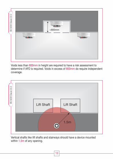
19
1 The system complies with original specification / design, if any changes have been made they have been approved by the designer.
2 System has been installed to meet the requirements of specified category, if not specified or known, commissioning engineer should state category that system appears to be installed to.
3 Wiring of detector / sounder circuits and mains supply wired in required fire resistant cable, standard or enhanced.
4 Cables are segregated and mechanically protected as required, suitably supported (no plastic clips, cable ties or trunking as the sole means of support) as per the cable manufacturers requirements.
5 Mains supply is a dedicated supply, suitably fused, and provides local double pole isolation which is correctly labelled.
6 Junction boxes are correctly labelled, identified on drawings, and use fire resistant terminal blocks.
7 All cable continuity and insulation resistance results are recorded.
8 Current requirements of the system under quiescent and alarm conditions are measured and relevant calculations carried out to ensure standby battery(s) are suitable for system requirements.
9 All standby batteries are clearly marked with date of installation, such that this date can be seen without removing batteries from equipment.
10 Minimum of two sounders are installed on a minimum of two sounder circuits i.e. at least one sounder on each of two sounder circuits.
11 Circuit wiring is correctly labelled and terminated in all control and ancillary equipment.
12 Sound pressure levels have been checked and recorded, and meet the requirements of BS 5839 Part 1.
13 Detector type and spacing have been checked and are installed to meet the required system category.
14 Manual call points are located correctly and travel distance is appropriate to the usage of the building.
15 Remote signalling has been checked to ensure correct operation, to relevant point of reception.
16 Zone chart(s) have been located in all appropriate locations i.e. adjacent to all control equipment and repeaters.
17 As fitted drawings are complete and have been updated where required.
18 Log book and operating instructions have been given to the responsible person.
19 Relevant certification is provided to user or purchaser of the system.
20 Responsible person(s) have been provided with adequate training in the operation of the system and the avoidance of false alarms.
Please note that this check list should only be taken as a suggested list andreference to the appropriate sections of BS 5839 part 1 is advised. Appropriatecertification should also be completed.
Suggested Installation / Commissioning / Handover Checklist
CC1608_Fire Systems Design Guide_Update1_Layout 1 11/03/2010 09:58 Page 19

Cooper Lighting and Safety Ltd - UKWheatley Hall Road, Doncaster, South Yorkshire. DN2 4NB.
www.cooperfire.com
SalesT: +44 (0)1302 303999F: +44 (0)1302 303333E: [email protected]
TechnicalT: +44 (0)1302 303350F: +44 (0)1302 303332E: [email protected]
ExportT: +44 (0)1302 303250F: +44 (0)1302 303251E: [email protected]
ServiceT: +44 (0)1302 303352F: +44 (0)1302 303332E: [email protected]
IrelandT: 00 353 6671 42858F: 00 353 6671 42861
CC1608_Fire Systems Design Guide_Update1_Layout 1 11/03/2010 09:58 Page 20