Embed Size (px)
Citation preview
The financial benefit of using borehole radar to delineate mining
blocks in underground platinum mines
by
Petro du Pisani
Submitted in partial fulfilment of the requirements for the degree MSc. (Earth Science
Management and Practice) in the Faculty of Natural and Agricultural Science
University of Pretoria
Pretoria
October 2007
©© UUnniivveerrssiittyy ooff PPrreettoorriiaa
TABLE OF CONTENTS
SUMMARY...................................................................................................................3 LIST OF ABBREVIATIONS........................................................................................5 LIST OF FIGURES .......................................................................................................6 LIST OF TABLES.........................................................................................................9 1 INTRODUCTION ...............................................................................................10
1.1 Objectives of the study.................................................................................10 1.2 The Platmine Research Collaborative..........................................................12 1.3 Delimitations................................................................................................12
2 BOREHOLE RADAR .........................................................................................13 3 THE MERENSKY REEF AT RPM AMANDELBULT SECTION...................16
3.1 Regional setting of RPM Amandelbult Section...........................................16 3.2 History of the Amandelbult Mine ................................................................18 3.3 Regional Geology of the Merensky Reef.....................................................18 3.4 Regional Geology of the Merensky Reef at Amandelbult Section..............19 3.5 Stratigraphy at Amandelbult Section ...........................................................20
3.5.1 Stratigraphy related to borehole radar penetration and reflection.....20 3.5.2 Upper pseudoreef (P2 marker) ............................................................26 3.5.3 P2 hanging wall marker.......................................................................27 3.5.4 Footwall marker...................................................................................27 3.5.5 Merensky Reef unit...............................................................................28 3.5.6 Bastard Reef unit..................................................................................29 3.5.7 Notes on the UG2 chromitite ...............................................................30
4 POTHOLES .........................................................................................................31 4.1 Potholes in the Western Bushveld Complex................................................31 4.2 Potholes at Amandelbult Section .................................................................33 4.3 The influence of potholes on mining ...........................................................36
4.3.1 Mining of the Merensky Reef at Amandelbult Section .........................36 4.3.2 Influence of potholes in mining the Merensky Reef at Amandelbult
Section..................................................................................................38 5 CASE STUDY.....................................................................................................40
5.1 Introduction..................................................................................................40 5.2 Borehole radar survey design.......................................................................41 5.3 Borehole radar results ..................................................................................49
5.3.1 Methodology ........................................................................................49 5.3.2 Borehole 4 ............................................................................................49 5.3.3 Borehole 2 ............................................................................................53 5.3.4 Borehole 1 ............................................................................................55 5.3.5 Borehole 3 ............................................................................................57 5.3.6 Contouring of geological and borehole radar illumination line
coordinates...........................................................................................59 5.3.7 Three-dimensional surface (all boreholes) ..........................................62
6 COST-BENEFIT ANALYSIS.............................................................................65 6.1 Introduction..................................................................................................65 6.2 Assumptions.................................................................................................66
6.2.1 Definition of borehole radar coverage and delineation ......................66 6.2.2 Values used in cost-benefit analysis ....................................................67
6.3 Ore body definition ......................................................................................68
1
6.3.1 Geological drilling...............................................................................69 6.3.2 Borehole radar along a single line ......................................................71 6.3.3 Geological intersect drilling vs. borehole radar .................................71 6.3.4 Borehole radar over the entire block...................................................72 6.3.5 Geostatistical increase in confidence ..................................................75
6.4 Mine design.................................................................................................77 6.4.1 Area of Merensky Reef sampled with standard geological drilling ....78 6.4.2 Area of Merensky Reef sampled using borehole radar........................79 6.4.3 Discussion ............................................................................................81
6.5 Development ...............................................................................................82 6.6 Extraction....................................................................................................85
6.6.1 Deferred income...................................................................................85 6.6.2 Labour efficiency .................................................................................85
6.7 Processing ....................................................................................................87 7 CONCLUSIONS AND RECOMMENDATIONS ..............................................88
7.1 Conclusions..................................................................................................88 7.2 Recommendations........................................................................................90
8 ACKNOWLEDGEMENTS.................................................................................93 9 REFERENCES ....................................................................................................95 APPENDIX A BOREHOLE INFORMATION .................................................100
Rock and stratigraphy codes ..................................................................................100 Borehole information for borehole 1 .....................................................................101 Borehole information for borehole 2 .....................................................................102 Borehole information for borehole 3 .....................................................................103 Borehole information for borehole 4 .....................................................................104
APPENDIX B BOREHOLE RADAR ILLUMINATION LINE COORDINATES ....................................................................................................105
Borehole 1: Borehole radar illumination line coordinates – dip direction.............105 Borehole 1: Borehole radar illumination line coordinates – strike direction.........106 Borehole 2: Borehole radar illumination line coordinates – strike direction.........107 Borehole 3: Borehole radar illumination line coordinates – dip direction.............108 Borehole 3: Borehole radar illumination line coordinates – strike direction.........109 Borehole 4: Borehole radar illumination line coordinates – dip direction.............110 Borehole 4: Borehole radar illumination line coordinates – strike direction.........111
2
SUMMARY
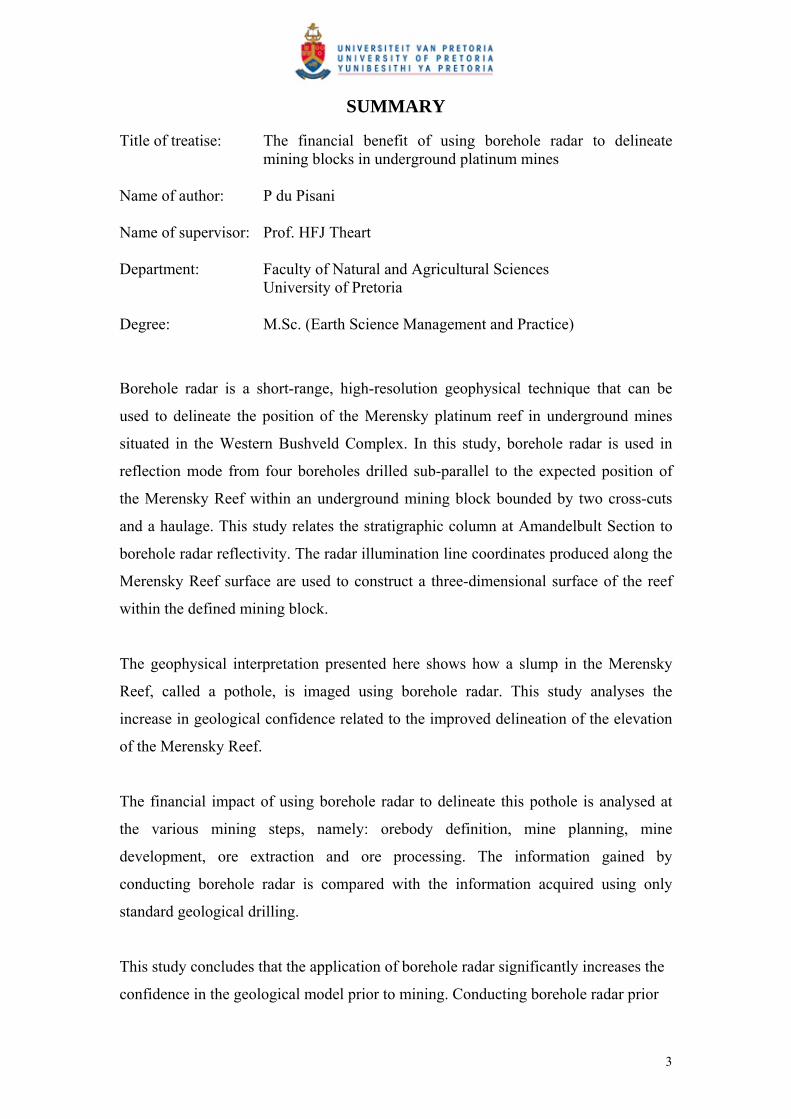
Title of treatise: The financial benefit of using borehole radar to delineate mining blocks in underground platinum mines
Name of author: P du Pisani Name of supervisor: Prof. HFJ Theart Department: Faculty of Natural and Agricultural Sciences University of Pretoria Degree: M.Sc. (Earth Science Management and Practice)
Borehole radar is a short-range, high-resolution geophysical technique that can be
used to delineate the position of the Merensky platinum reef in underground mines
situated in the Western Bushveld Complex. In this study, borehole radar is used in
reflection mode from four boreholes drilled sub-parallel to the expected position of
the Merensky Reef within an underground mining block bounded by two cross-cuts
and a haulage. This study relates the stratigraphic column at Amandelbult Section to
borehole radar reflectivity. The radar illumination line coordinates produced along the
Merensky Reef surface are used to construct a three-dimensional surface of the reef
within the defined mining block.
The geophysical interpretation presented here shows how a slump in the Merensky
Reef, called a pothole, is imaged using borehole radar. This study analyses the
increase in geological confidence related to the improved delineation of the elevation
of the Merensky Reef.
The financial impact of using borehole radar to delineate this pothole is analysed at
the various mining steps, namely: orebody definition, mine planning, mine
development, ore extraction and ore processing. The information gained by
conducting borehole radar is compared with the information acquired using only
standard geological drilling.
This study concludes that the application of borehole radar significantly increases the
confidence in the geological model prior to mining. Conducting borehole radar prior
3

to mining improves mine planning and development, ensures that less waste is mined,
facilitates the effective deployment of labour crews, prevents waste being sent to the
processing plant and avoids deferring income until a later date. Recommendations are
made on how to plan for and include borehole radar in the mining process.
4
LIST OF ABBREVIATIONS
BH Borehole
BHR Borehole radar
CSIR Council for Scientific and Industrial Research
GPR Ground Penetrating Radar
PGE Platinum Group Elements
RPM Rustenburg Platinum Mines
SAIMM South African Institute of Mining and Metallurgy
SAMREC South African Mineral Resources Committee
SG Specific Gravity
5
LIST OF FIGURES
Figure 1: A geological map of the Bushveld Complex in South Africa, showing the distribution of the main economic minerals, after Viljoen and Schürmann (1998)..............................................................................................................................10
Figure 2: Schematic for the Aardwolf BR40 instrument, showing the radar transmitter, receiver, optical-fibre links, winch and control unit (Vogt 2002) .......................13
Figure 3: The optimal survey geometry for a borehole radar reflection survey orients the borehole parallel to sub-parallel to the intended radar target (Image courtesy CSIR) ...................................................................................................................15
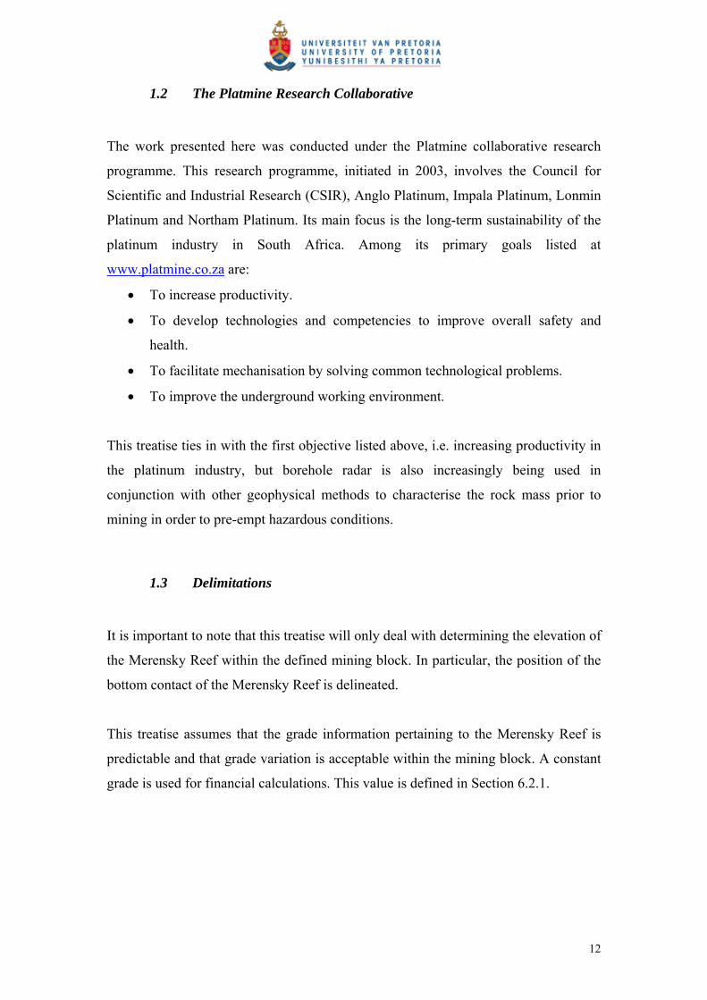
Figure 4: Locality plan showing Amandelbult Section in relation to the major geological rock types of the Bushveld Complex, after Viljoen et al., 1986b ......17
Figure 5: Map of Amandelbult Section’s lease area, showing the main geological features and farm boundaries (Viljoen et al., 1986b) ..........................................17
Figure 6: Radar performance prediction for a smooth planar target after Noon et al. (1998)...................................................................................................................21
Figure 7: Distribution of loss-tangent values for (A) anorthosite, (B) norite and (C) pyroxenite after Du Pisani and Vogt (2003) ........................................................22
Figure 8: The distribution of permittivity values for (A) anorthosite (B) norite and (C) pyroxenite at a radar frequency of 64 MHz after Du Pisani and Vogt (2003).....24
Figure 9: General stratigraphic column for Amandelbult Section, showing the position of the borehole radar holes, the expected radar reflectors and the range of the borehole radar instrument (stratigraphic column from A guide to the geology of Amandelbult)........................................................................................................25
Figure 10: Stratigraphic column for the economic reefs at Amandelbult Section after Viljoen et al., 1986b.............................................................................................31
Figure 11: Merensky Reef facies map for the Western Bushveld Complex, after Viljoen and Schürmann (1998)............................................................................33
Figure 12: Distribution of pothole structures and isopach map for normal Merensky Reef at Amandelbult Section after Viljoen et al., 1986b.....................................34
Figure 13: Generalised pothole model for the potholes within the Swartklip facies as developed by Viljoen (1994) ...............................................................................35
Figure 14: Generalised pothole model for pothole formation at Amandelbult Section from A guide to the geology of Amandelbult .......................................................35
Figure 15: Diagram showing the simplified methodology for conventional breast stoping..................................................................................................................37
Figure 16: The process of mining thin reefs using conventional breast stoping: (A) Cross-cuts are developed from the haulage to the reef. (B) Raises are developed along the reef elevation. (C) Panels are mined out from opposite raise lines. (D) A dip pillar is left in the middle of the mining block to provide support. (After Du Pisani and Vogt, 2004)...................................................................................37
Figure 17: Borehole layouts considered for the borehole radar case study at Amandelbult Section. The arrowed lines indicate possible borehole positions...42
Figure 18: Simplified mine plan showing the positions of the four boreholes drilled for borehole radar as red lines and the location of geological reef intersect boreholes ..............................................................................................................43
Figure 19: The location of the borehole radar holes in relation to some of the geological drilling in the vicinity.........................................................................44
Figure 20: A) Radargram for borehole 1 showing how the Merensky and Bastard Reef reflectors plot at similar distances away from the borehole position; and...........46
6

Figure 21: Schematic showing the case-study layout in section (looking from the east), with the boreholes (red lines) drilled between the Bastard and Merensky reefs, with boreholes angled towards the Bastard Reef .......................................48
Figure 22: Case-study layout in section, showing radar boreholes as observed from the west. This is the hypothetical base model with flat surfaces for the Merensky and Bastard reefs.........................................................................................................48
Figure 23: The radargram for borehole 4 without (top) and with interpretation (bottom). The Merensky Reef reflector is indicated by a yellow dotted line and the Bastard Reef reflector is indicated by a white dotted line. ............................52
Figure 24: Three-dimensional visualisation for the borehole radar data acquired in borehole 4. The Merensky Reef surface is indicated in blue, while the Bastard Reef surface is shown in red. The radar illumination line is tracked along the Merensky Reef surface. .......................................................................................53
Figure 25: Radargram for borehole 2 without (top) and with interpretation (bottom). The Merensky Reef reflector is indicated by the yellow dotted line, while the Bastard Reef reflector is shown by a white dotted line. ......................................54
Figure 26:Three-dimensional visualisation in Fresco for the borehole radar data acquired in borehole 2. The Merensky Reef surface is shown in blue and the Bastard Reef surface is shown in red. ..................................................................55
Figure 27: Radargram for borehole 1 without (top) and with interpretation (bottom). The Merensky Reef reflector is shown as a yellow dotted line and the Bastard Reef reflector is shown as a white dotted line. ....................................................56
Figure 28: Three-dimensional visualisation for borehole radar data acquired in borehole 1. The Merensky Reef surface is shown in red and the Bastard Reef surface is shown in blue. ......................................................................................57
Figure 29: Radargram for borehole 3 without (top) and with interpretation (bottom). The interpreted Merensky Reef reflector is shown as a yellow dotted line and the Bastard Reef reflector is shown as a white dotted line. .......................................58
Figure 30: Three-dimensional visualisation for borehole radar data acquired in borehole 3. The Merensky Reef reflector is shown as a blue surface..................59
Figure 31: Contour map produced by gridding the Merensky Reef elevation as logged from geological boreholes in the vicinity of the borehole radar survey ..............60
Figure 32: Contour map produced by gridding the illumination line coordinates produced by conducting borehole radar in boreholes 1 to 4................................61
Figure 33: Three-dimensional surfaces constructed for the reef block imaged by borehole radar: A) the grey surface constructed from geological borehole information only, and B) the blue surface constructed by using the borehole radar illumination lines .................................................................................................63
Figure 34: The surface produced by gridding the XYZ-coordinates from the borehole radar modelling, with the positions of the imaged pothole indicated ..................64
Figure 35: Schematic representation of A) the area covered by borehole radar, and B) the area covered by the pothole defined by borehole radar .................................66
Figure 36: Daily platinum prices in 2006, given in US$, after Platinum 2007 ...........67 Figure 37: Average 2006 rand/US dollar exchange rate (www.gocurrency.com) ......68 Figure 38: Mineral reserves and resources according to the SAMREC code (2000)..69 Figure 39: A map showing the area covered by the four borehole radar boreholes,
indicating the positions of geological boreholes drilled prior to the borehole radar survey...................................................................................................................70
7
Figure 40: Cost of borehole radar compared with A) the value of the in situ platinum in block delineated by borehole radar and B) the production cost per tonne of platinum ...............................................................................................................75
Figure 41: Borehole radar survey layout indicating vertical boreholes meant to “cover” mining block between 9W and 8W crosscut on 10-Level......................78
Figure 42: The first Fresnel zone (Vogt 2003) ............................................................79 Figure 43: The areas from which borehole radar data is gathered for boreholes 1 to 4
..............................................................................................................................80 Figure 44: Increase in sampling area if borehole radar is conducted ..........................81 Figure 45: Hypothetical monthly advance of a mining crew along a 35 m long panel86 Figure 46: Proposed borehole layout in section for applying borehole radar to detect
geological deviations prior to mining ..................................................................91 Figure 47: Proposed borehole radar layout in plan for the prediction of geological
disruptions prior to mine development ................................................................91 Figure 48: Optimisation of mine development after the application of borehole radar
..............................................................................................................................92
8
LIST OF TABLES
Table 1: The loss tangent and radar penetrations for anorthosite, norite and pyroxenite ..................................................................................................................23
Table 2: Borehole information for the radar boreholes ...............................................47 Table 3: Geological boreholes in the area covered by the borehole radar surveys. The
distance from the borehole collar to the bottom Merensky Reef contact is shown in the last column. ................................................................................................71
Table 4: Cost per reef elevation point for geological drilling, compared with conducting a borehole radar survey .....................................................................72
Table 5: Survey lengths for all four radar boreholes ...................................................73 Table 6: Conclusions summarised for applying only geological drilling, compared
with conducting borehole radar ...........................................................................89 Table 7: The impact of borehole radar at the five stages of mining an ore body ........90
9

1 INTRODUCTION
1.1 Objectives of the study
This treatise aims to quantify the cost benefit that can be achieved if borehole radar is
applied as a predictive geological tool ahead of mining.
A case study was conducted at Anglo Platinum’s Amandelbult Section. The treatise
describes how the optimal survey design was designed in order to effectively image a
mining block. A fan of boreholes was surveyed with borehole radar, which provided a
detailed three-dimensional surface representing the Merensky Reef. A cost-benefit
analysis was conducted to determine whether the information provided by borehole
radar in this mining block provided any significant financial benefits to the mine.
The Bushveld Complex, situated north of Pretoria in South Africa, contains the
world’s largest known resource of platinum (Viljoen and Schürmann, 1998). The
distribution of the platinum resources in relation to other mineral deposits is shown in
Figure 1.
Figure 1: A geological map of the Bushveld Complex in South Africa, showing the distribution of the main economic minerals, after Viljoen and Schürmann (1998)
10

Economic concentrations of platinum are present in the Merensky Reef: a feldspathic
pegmatoidal pyroxenite and the UG2 chromitite. These platinum-rich layers are
interspersed with layers of anorthosite, norite and pyroxenite.
On a regional scale, these thin tabular ore bodies (locally called reefs) are continuous
for tens to hundreds of kilometres, but on a smaller mine-block scale these reefs are
often disrupted by various geological structures such as dykes, iron-rich ultramafic
pegmatites (IRUPs), faults and potholes. Potholes are the most common disruption
and cause most challenges to mining these reefs.
In this treatise, a geological disruption caused by a pothole is examined. In a pothole,
the reef transgresses its footwall layers, resulting in slumps that have diameters that
can be metres to tens of metres deep and wide (Viljoen and Schürmann, 1998). The
reef is often pinched out at the edges of the pothole, resulting in degraded ore
reserves. Potholes inevitably lead to significant losses and predicting their presence
ahead of mining is advantageous for a number of reasons:
Less waste rock is mined, resulting in a significant cost benefit to the mine.
Improved knowledge of the ore body means that less money is spent on
unnecessary development towards severely disrupted or degraded reef.
Mining can be planned smarter so that, for example, support pillars are left where
less ore is present due to potholing.
If it is known that mining is approaching a pothole, mining can be relocated
timeously and work crews can be moved to a different location, i.e. the work
force is used more efficiently.
Pothole edges are often related to unstable hanging wall conditions, which could
lead to falls of ground. If the pothole edge is delineated before mining starts,
additional precautionary measures can be taken to ensure the safety of mine
workers.
11
1.2 The Platmine Research Collaborative
The work presented here was conducted under the Platmine collaborative research
programme. This research programme, initiated in 2003, involves the Council for
Scientific and Industrial Research (CSIR), Anglo Platinum, Impala Platinum, Lonmin
Platinum and Northam Platinum. Its main focus is the long-term sustainability of the
platinum industry in South Africa. Among its primary goals listed at
www.platmine.co.za are:
To increase productivity.
To develop technologies and competencies to improve overall safety and
health.
To facilitate mechanisation by solving common technological problems.
To improve the underground working environment.
This treatise ties in with the first objective listed above, i.e. increasing productivity in
the platinum industry, but borehole radar is also increasingly being used in
conjunction with other geophysical methods to characterise the rock mass prior to
mining in order to pre-empt hazardous conditions.
1.3 Delimitations
It is important to note that this treatise will only deal with determining the elevation of
the Merensky Reef within the defined mining block. In particular, the position of the
bottom contact of the Merensky Reef is delineated.
This treatise assumes that the grade information pertaining to the Merensky Reef is
predictable and that grade variation is acceptable within the mining block. A constant
grade is used for financial calculations. This value is defined in Section 6.2.1.
12

2 BOREHOLE RADAR
Borehole radar is ground penetrating radar (GPR) applied from within a borehole.
GPR is a geophysical technique whereby radio waves are transmitted into the ground
to locate buried objects or hidden interfaces (Daniel et al., 2004). GPR measures
differences in the dielectric property permittivity, and the distance that radar waves
travel in a medium is determined by its conductivity (Du Pisani and Vogt, 2003).
A typical bi-static borehole radar instrument consists of separate transmitter and
receiver probes that are deployed inside a borehole. In this study, the CSIR’s
Aardwolf BR40 was used to acquire the borehole radar data. This instrument has a
centre frequency of 40 MHz and a vertical resolution of approximately 1 m (Vogt et
al., 2005). A schematic of the Aardwolf BR40 is shown in Figure 2.
Figure 2: Schematic for the Aardwolf BR40 instrument, showing the radar transmitter, receiver, optical-fibre links, winch and control unit (Vogt 2002)
Borehole radar can be applied in reflection mode from within a single borehole (Vogt,
2006) or in transmission mode, whereby the transmitter is located in one borehole and
the receiver in an adjacent borehole. In transmission mode, borehole radar can
determine whether conductive material is present between two boreholes (Turner et
al., 2000).
13

For the study presented in this treatise, borehole radar is used in single-borehole
reflection mode to image the boundary of the Merensky Reef within a section of
Anglo Platinum’s Amandelbult Section.
In borehole radar reflection mode, radar waves are transmitted into the rock mass and
the time taken for these waves to travel to a reflective interface is measured in
nanoseconds (Vogt et al., 2005). If the velocity of the radar waves in the rock mass is
known, the distance to the interface can be calculated.
In order for a reflection borehole radar survey to be successful, the following factors
are of importance (Vogt, 2006):
The borehole from which borehole radar is applied should be oriented parallel
or sub-parallel to the target to be imaged, as shown in Figure 3.
There should be a significant permittivity contrast between the target and its
host rocks.
The technique works best if the borehole is situated in a host rock that is
resistive and delineates a target that is conductive.
The reflective contact should be sharp as opposed to gradationally changing
into a different rock type.
More technical information about borehole radar will be discussed throughout this
treatise as it becomes necessary.
14

Figure 3: The optimal survey geometry for a borehole radar reflection survey orients the borehole parallel to sub-parallel to the intended radar target (Image courtesy CSIR)
15

3 THE MERENSKY REEF AT RPM AMANDELBULT
SECTION
3.1 Regional setting of RPM Amandelbult Section
Anglo Platinum’s Amandelbult Section is located in South Africa’s Limpopo
province (Figure 4). The mine is approximately 100 km north of Rustenburg and
40 km south of Thabazimbi. As seen in Figure 5, Amandelbult Section’s lease area is
in the shape of a rectangle with the long axis oriented NE-SW, and approximately
4 km wide on the short side and 20 km wide on the long side (Viljoen et al., 1986b).
The topography surrounding the mine is relatively flat and the surface is covered by a
thin layer of black turf soil. The only noticeable topography is a group of small hills to
the south of the main entrance of the mine, which are locally termed pyramid
gabbros. According to Viljoen et al. (1986b), these small hills form part of the
Bushveld Complex’s Main Zone, and they consist of gabbro-norite, which is the
prevalent rock type in the Main Zone of the Bushveld Complex.
To the west and north of Amandelbult Section, the quartzites of the Transvaal
Supergroup form the Witfontein Mountains. In the north-eastern part of the lease area,
the Crocodile River runs from south to north.
16
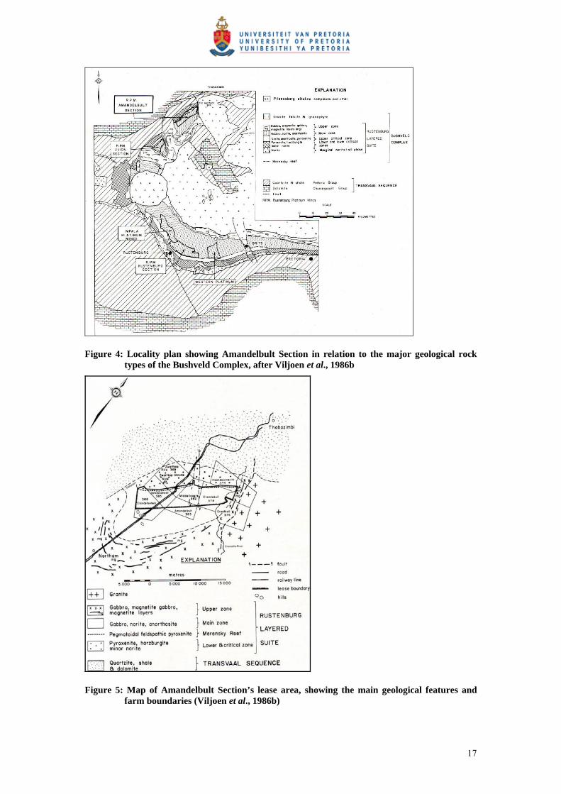
Figure 4: Locality plan showing Amandelbult Section in relation to the major geological rock types of the Bushveld Complex, after Viljoen et al., 1986b
Figure 5: Map of Amandelbult Section’s lease area, showing the main geological features and farm boundaries (Viljoen et al., 1986b)
17
3.2 History of the Amandelbult Mine
The Merensky Reef was discovered by A.F. Lombaard in 1924 (Viljoen et al.,
1986b). Although the Merensky Reef was discovered in the Eastern Bushveld, almost
all of the platinum mining that occurred up until the mid-Seventies in South Africa
was due to the extraction of the Merensky Reef in the Western Bushveld (Cawthorn,
1999).
The Merensky Reef was discovered in the Western Bushveld near Rustenburg in 1925
(Viljoen et al., 1986b), leading to more widespread exploration. Amandelbult Section
was prospected in 1926 by the Steelpoort Platinum Syndicate. Shortly thereafter,
ownership of Amandelbult transferred to Potgietersrust Platinum Limited, but interest
in the area decreased during the 1930s’ Depression, during which all platinum mining
was suspended.
Rustenburg Platinum Mines (RPM), which eventually became part of Anglo
Platinum, acquired the mineral rights for Amandelbult Section in 1964 and mining
eventually commenced on the farm Schilpadsnest in 1974 (Viljoen et al., 1986b).
Platinum production at Amandelbult ceased in 1975 due to a slump in the platinum
market, but after it restarted in 1976, production increased on a yearly basis
(www.platinummetalsreview.co.za).
Currently both the Merensky and UG2 reefs are mined at Amandelbult Section.
Amandelbult is expecting to increase the rate of equivalent refined platinum
production to approximately 625,000 ounces in 2007 (Anglo Platinum Annual Report
2006).
3.3 Regional Geology of the Merensky Reef
The Merensky Reef occurs in the Upper Critical Zone of the Bushveld Complex.
According to Viljoen (1999), the reef has been delineated for approximately 145 km
in the Western Lobe of the Bushveld Complex. Underground and opencast extraction
of the reef is taking place over a strike distance of approximately 90 km (Viljoen et
18
al., 1986b). The Merensky Reef’s dip changes from approximately 9° to 12° as it is
traced inwards towards the centre of the Bushveld Complex, with steeply dipping
exceptions in parts of the complex.
The thickness of the Merensky Reef can vary between 2 cm and 14 m (Viljoen et al.,
1986b). Its down-dip extension has been traced with the help of seismic surveys for
up to 50 km, and to depths of 6 km (Du Plessis and Kleinwegt, 1987). Since mining
on the Merensky Reef commenced in 1929, a large amount of data has been gathered
about this particular reef (Viljoen, 1999), and it is evident that the Merensky Reef
varies dramatically regionally with regard to geology, mineralogy and PGE-grade
distribution (Kinloch and Peyerl, 1990; Eales et al., 1993; Viljoen et al., 1986a;
1986b; Viljoen, 1994; Eales and Cawthorn, 1996; Viljoen and Schürmann, 1998).
Viljoen (1999) says the Merensky Reef is typically a heterogeneous pegmatoidal
feldspathic pyroxenite bounded by two thin chromitite layers, generally referred to as
Bottom Chromitite and Top Chromitite. Viljoen (1999) continues to say that PGE-
grades generally increase as the pegmatoidal nature of the reef increases.
This treatise does not examine grade distribution within the Merensky Reef, but
concentrates on delineating the position of the reef in three dimensions for mining
purposes.
3.4 Regional Geology of the Merensky Reef at Amandelbult Section
As seen in Figure 4, Amandelbult Section is located in the north-western lobe of the
Bushveld Complex (Viljoen et al., 1986b). The platiniferous layers, i.e. the Merensky
and UG2 reefs, occur within a portion of the Lower, Critical and Main zones of the
Bushveld Complex, with Upper Zone rocks above (Viljoen et al., 1986b). The Upper
Zone layers cut off the bottom three layers to the north and south of Amandelbult
Section, resulting in an area known as the “northern gap” located to the south of the
mine.
19

According to A guide to the geology at Amandelbult, which is an updated version of
the geology of Amandelbult as described by Viljoen et al. (1986b), it has been
established by underground workings that the Merensky Reef continues to the north-
east of the mine.
3.5 Stratigraphy at Amandelbult Section
3.5.1 Stratigraphy related to borehole radar penetration and reflection
3.5.1.1 Radar penetration For borehole radar to be successful, the radar waves need to travel from the borehole
to the target surface, i.e. the rocks between the borehole and target surface need to be
translucent to radar waves. As described by Du Pisani and Vogt (2003), the
attenuation, or rate of decay, of radar waves is controlled by the conductivity of the
rocks through which they are travelling. If the rocks between the borehole and target
are too conductive, the radar waves will attenuate rapidly and not reach their intended
target.
Radar attenuation is usually described through the loss tangent:
0
tan
r
(1)
As described by Vogt et al. (2005), the conductivity, σ, and permittivity, ε, are
measured at a specific frequency, f. This frequency can be converted to the angular
frequency ω, which is defined by ω = 2лf. In equation (1), r is the relative permittivity
and is the permittivity of free space. 120 10854.8
Turner and Siggins (1994) explained that for most rocks suitable for GPR, the loss
tangent is constant over the frequency range of the GPR instrument. Vogt (2000)
showed that this constant loss-tangent estimation is an acceptable approximation to
measured properties, when he analysed a database of 15,057 electrical property
measurements. If a constant loss tangent is used, a nomogram from Noon et al. (1998)
20
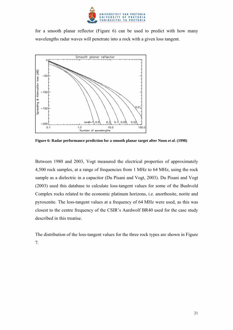
for a smooth planar reflector (Figure 6) can be used to predict with how many
wavelengths radar waves will penetrate into a rock with a given loss tangent.
Figure 6: Radar performance prediction for a smooth planar target after Noon et al. (1998)
Between 1980 and 2003, Vogt measured the electrical properties of approximately
4,500 rock samples, at a range of frequencies from 1 MHz to 64 MHz, using the rock
sample as a dielectric in a capacitor (Du Pisani and Vogt, 2003). Du Pisani and Vogt
(2003) used this database to calculate loss-tangent values for some of the Bushveld
Complex rocks related to the economic platinum horizons, i.e. anorthosite, norite and
pyroxenite. The loss-tangent values at a frequency of 64 MHz were used, as this was
closest to the centre frequency of the CSIR’s Aardwolf BR40 used for the case study
described in this treatise.
The distribution of the loss-tangent values for the three rock types are shown in Figure
7.
21

A (Anorthosite)
B (Norite)
C (Pyroxenite)
Figure 7: Distribution of loss-tangent values for (A) anorthosite, (B) norite and (C) pyroxenite after Du Pisani and Vogt (2003)
The system performance of the CSIR’s Aardwolf BR40 is approximately 120 dB
(Vogt, pers comm). As described by Du Pisani and Vogt (2003), the wavelength in
metres can be estimated as 100/f, where f is the frequency in MHz. For a 40 MHz
system, such as the Aardwolf BR40, the wavelength is then 2.5 m.
In Table 1, the typical loss-tangent values for anorthosite, norite and pyroxenite and
their radar penetrations in these rocks, as determined from the nomogram in Figure 6,
are summarised.
22
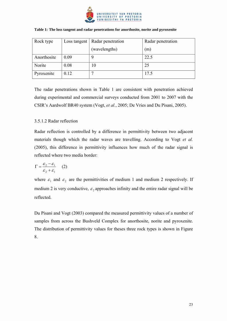
Table 1: The loss tangent and radar penetrations for anorthosite, norite and pyroxenite
Rock type Loss tangent Radar penetration
(wavelengths)
Radar penetration
(m)
Anorthosite 0.09 9 22.5
Norite 0.08 10 25
Pyroxenite 0.12 7 17.5
The radar penetrations shown in Table 1 are consistent with penetration achieved
during experimental and commercial surveys conducted from 2001 to 2007 with the
CSIR’s Aardwolf BR40 system (Vogt, et al., 2005; De Vries and Du Pisani, 2005).
3.5.1.2 Radar reflection Radar reflection is controlled by a difference in permittivity between two adjacent
materials though which the radar waves are travelling. According to Vogt et al.
(2005), this difference in permittivity influences how much of the radar signal is
reflected where two media border:
12
12
(2)
where 1 and 2 are the permittivities of medium 1 and medium 2 respectively. If
medium 2 is very conductive, 2 approaches infinity and the entire radar signal will be
reflected.
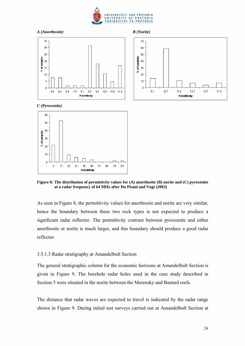
Du Pisani and Vogt (2003) compared the measured permittivity values of a number of
samples from across the Bushveld Complex for anorthosite, norite and pyroxenite.
The distribution of permittivity values for theses three rock types is shown in Figure
8.
23
A (Anorthosite)
B (Norite)
C (Pyroxenite)
Figure 8: The distribution of permittivity values for (A) anorthosite (B) norite and (C) pyroxenite at a radar frequency of 64 MHz after Du Pisani and Vogt (2003)
As seen in Figure 8, the permittivity values for anorthosite and norite are very similar,
hence the boundary between these two rock types is not expected to produce a
significant radar reflector. The permittivity contrast between pyroxenite and either
anorthosite or norite is much larger, and this boundary should produce a good radar
reflector.
3.5.1.3 Radar stratigraphy at Amandelbult Section The general stratigraphic column for the economic horizons at Amandelbult Section is
given in Figure 9. The borehole radar holes used in the case study described in
Section 5 were situated in the norite between the Merensky and Bastard reefs.
The distance that radar waves are expected to travel is indicated by the radar range
shown in Figure 9. During initial test surveys carried out at Amandelbult Section at
24
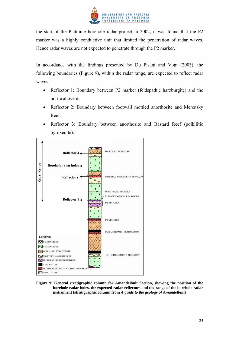
the start of the Platmine borehole radar project in 2002, it was found that the P2
marker was a highly conductive unit that limited the penetration of radar waves.
Hence radar waves are not expected to penetrate through the P2 marker.
In accordance with the findings presented by Du Pisani and Vogt (2003), the
following boundaries (Figure 9), within the radar range, are expected to reflect radar
waves:
Reflector 1: Boundary between P2 marker (feldspathic harzburgite) and the
norite above it.
Reflector 2: Boundary between footwall mottled anorthosite and Merensky
Reef.
Reflector 3: Boundary between anorthosite and Bastard Reef (poikilitic
pyroxenite).
Figure 9: General stratigraphic column for Amandelbult Section, showing the position of the borehole radar holes, the expected radar reflectors and the range of the borehole radar instrument (stratigraphic column from A guide to the geology of Amandelbult)
25

Only the rocks that are within the borehole radar’s range are discussed within the
context of radar penetration and reflectivity in the next sections.
The units that are examined include:
Upper pseudoreef (P2 marker)
P2 hanging wall marker
Footwall marker
Merensky Reef unit
Bastard Reef unit
3.5.2 Upper pseudoreef (P2 marker)
The P2 marker comprises feldspathic harzburgite (Viljoen et al., 1986b). As seen in
Figure 9, the immediate footwall of the P2 marker is anorthosite.
The P2 marker is split into two layers in the south-western part of Amandelbult mine
(Viljoen et al., 1986b). The lower P2 layer is approximately 3 m thick, and is
separated from the top P2 layer by what is termed the middling anorthosite (0 m to
1.2 m). The top P2 layer can be up to 1 m in thickness. Both P2 layers usually have
thin chromitite stringers at their base. To the north-east of the mine, the two P2 layers
merge into one composite feldspathic harzburgite (Viljoen et al., 1986b).
The overlying cycle of the P2 starts with a 10 mm-thick chromitite stringer (Viljoen et
al., 1986b), which provides a sharp reflective contact for radar waves. Above this thin
chromitite there is approximately 10 cm to 15 cm of coarse pegmatoidal feldspathic
harzburgite, which changes gradually into a 2 m-wide melanorite (Viljoen et al.,
1986b).
The dielectric properties of harzburgite have not been examined in detail, but it is the
author’s experience that the P2 is usually very conductive and that most of the radar
signal is reflected back when this unit is encountered. Both the sharp chromitite
boundary and coarse, conductive harzburgite contribute to the author’s observation
that radar waves generally do not penetrate through this unit.
26

According to Du Pisani and Vogt (2003), the boundary between pyroxenite and norite
provides a good radar reflection, and even though the boundary between the
harzburgite and norite is gradational, their difference in permittivity should contribute
towards imaging the P2 with borehole radar.
3.5.3 P2 hanging wall marker
The P2 hanging wall marker is a remarkably consistent marker horizon consisting of
an anorthosite layer on top of a pyroxenite layer (Viljoen et al., 1986b) inside the
melanorite above the P2 marker. This thin band is 10 cm to 15 cm thick, and occurs
approximately 70 cm above the P2 marker. Even though the boundary between
anorthosite and pyroxenite provides a good reflective target for radar (Du Pisani and
Vogt, 2003), the vertical resolution of the Aardwolf BR40 instrument is in the order
of 1 m (Vogt et al., 2005), hence this thin marker horizon will not be detected with
this instrument.
Upwards from the P2 hanging wall marker, the melanorite in which it occurs
gradationally changes into norite and then into anorthositic norite until it reaches a
very distinctive anorthosite band called the Footwall marker (Viljoen et al., 1986b).
3.5.4 Footwall marker
The thin (40 cm to 50 cm) anorthosite Footwall marker occurs approximately 8 m
above the P2 marker and approximately 10 m below the Merensky Reef (Viljoen et
al., 1986b). Above the Footwall marker there is 3 m to 5 m of norite, followed by 5 m
to 6 m of poikilitic anorthosite, after which the bottom chromitite stringer, signifying
the start of the Merensky Reef cycle, is reached (Viljoen et al., 1986b).
According to Du Pisani and Vogt (2003), the contact between anorthosite and norite
will not provide a significant radar contrast, hence it is not expected that any of the
anorthosite-norite boundaries between the P2 pseudoreef and Merensky Reef will be
imaged with borehole radar.
27
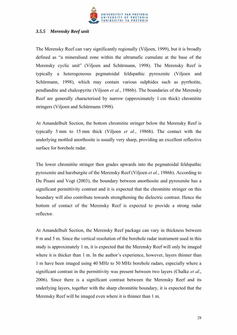
3.5.5 Merensky Reef unit
The Merensky Reef can vary significantly regionally (Viljoen, 1999), but it is broadly
defined as “a mineralised zone within the ultramafic cumulate at the base of the
Merensky cyclic unit” (Viljoen and Schürmann, 1998). The Merensky Reef is
typically a heterogeneous pegmatoidal feldspathic pyroxenite (Viljoen and
Schürmann, 1998), which may contain various sulphides such as pyrrhotite,
pendlandite and chalcopyrite (Viljoen et al., 1986b). The boundaries of the Merensky
Reef are generally characterised by narrow (approximately 1 cm thick) chromitite
stringers (Viljoen and Schürmann 1998).
At Amandelbult Section, the bottom chromitite stringer below the Merensky Reef is
typically 5 mm to 15 mm thick (Viljoen et al., 1986b). The contact with the
underlying mottled anorthosite is usually very sharp, providing an excellent reflective
surface for borehole radar.
The lower chromitite stringer then grades upwards into the pegmatoidal feldspathic
pyroxenite and harzburgite of the Merensky Reef (Viljoen et al., 1986b). According to
Du Pisani and Vogt (2003), the boundary between anorthosite and pyroxenite has a
significant permittivity contrast and it is expected that the chromitite stringer on this
boundary will also contribute towards strengthening the dielectric contrast. Hence the
bottom of contact of the Merensky Reef is expected to provide a strong radar
reflector.
At Amandelbult Section, the Merensky Reef package can vary in thickness between
0 m and 5 m. Since the vertical resolution of the borehole radar instrument used in this
study is approximately 1 m, it is expected that the Merensky Reef will only be imaged
where it is thicker than 1 m. In the author’s experience, however, layers thinner than
1 m have been imaged using 40 MHz to 50 MHz borehole radars, especially where a
significant contrast in the permittivity was present between two layers (Chalke et al.,
2006). Since there is a significant contrast between the Merensky Reef and its
underlying layers, together with the sharp chromitite boundary, it is expected that the
Merensky Reef will be imaged even where it is thinner than 1 m.
28
The top contact of the Merensky Reef is also characterised by a thin chromitite layer,
which is normally not thicker than 20 mm (Viljoen et al., 1986b). Above this
chromitite stringer there is a thin layer of poikilitic feldspathic pyroxenite which
gradationally changes into norite (Viljoen et al., 1986b).
Since the contact between the Merensky Reef pyroxenite and its overlying pyroxenite
is essentially a contact between two similar rock types, the top Merensky Reef contact
is not expected to be a good radar reflector. Furthermore, the hanging wall pyroxenite
above the top Merensky chromitite stringer grades into norite and although the
boundary between pyroxenite and norite provides a good radar reflector (Du Pisani
and Vogt, 2003) due to the gradational transition, a radar reflection is not expected.
The norite layer above the Merensky Reef is topped by a prominent mottled
anorthosite, which is 2 m to 3 m thick (Viljoen et al., 1986b). According to Du Pisani
and Vogt (2003), the boundary between norite and anorthosite does not have enough
of a dielectric contrast to produce a radar reflection.
The entire Merensky Reef cyclic unit from the pegmatoidal pyroxenite to the mottled
anorthosite is typically approximately 16 m thick (Viljoen et al., 1986b).
3.5.6 Bastard Reef unit
The Bastard Reef cyclic unit is very similar to the Merensky Reef cyclic unit, except
that this cycle is spread over a thickness of 32 m, where the Merensky unit is 16 m
thick (Viljoen et al., 1986b). The lower portion of the Bastard Reef cycle does not
contain pegmatoidal pyroxenite and it is also not characterised by a thin chromitite
base (Viljoen et al., 1986b). Instead, the Bastard Reef usually consists of a fine-
grained pyroxenite that changes gradationally into norite.
Since the poikilitic pyroxenite at the base of the Bastard Reef unit has a sharp contact
with the underlying mottled anorthosite, this contact should produce a good radar
29
reflection. According to Du Pisani and Vogt (2003), the contact between anorthosite
and pyroxenite will produce a good radar reflection.
3.5.7 Notes on the UG2 chromitite
As seen in Figure 10 when normal Merensky Reef is present, the UG2 chromitite is
expected 38.3 m beneath the Merensky Reef. The radar waves are not expected to
travel all the way from the borehole (drilled in Merensky Reef footwall norite) to the
UG2 due to two reasons:
1. The UG2 is too far from the borehole.
2. The feldspathic harzburgite P2 marker is expected to attenuate the radar
signal.
In order to evaluate the topography of the UG2 Reef with borehole radar, new radar
boreholes would have to be drilled below the P2 marker.
30

Figure 10: Stratigraphic column for the economic reefs at Amandelbult Section after Viljoen et al., 1986b
4 POTHOLES
4.1 Potholes in the Western Bushveld Complex
Irvine (1982) and Kruger (1990) described the Merensky Reef as paraconformable
with the underlying cumulates. According to Viljoen and Schürmann (1998), the
Merensky Reef forms a regional discontinuity in the western lobe of the Bushveld
Complex. Viljoen (1999) describes how the Merensky Reef can slump into its
footwall layers to form structures broadly termed potholes. According to Carr et al.
(1994), Merensky Reef potholes are significant disruptions to the normal magmatic
layering in the Upper Critical Zone of the Bushveld Complex.
According to Viljoen et al. (1986b), potholes are circular or elliptical in plan view,
and Viljoen (1999) states that a pothole can slump downwards for 1 m to tens of
31

metres. It is also possible for the Merensky Reef to transgress downwards in a step-
like fashion (Viljoen and Schürmann, 1998), with steps associated with steep portions
of thin contact reef. As the reef cascades downwards, it is also possible for
mineralised reef to form on various footwall units (Viljoen and Schürmann, 1998).
Various types of pothole structures and pothole reefs have been classified and
identified (Farquar, 1986; Leeb du Toit, 1986; Viljoen and Hieber, 1986; Kinloch and
Peyerl, 1990; Viljoen et al., 1986a; 1986b; Schürmann, 1991).
Wagner (1929) divided the Western Bushveld Complex rocks into the Rustenburg
facies to the south of Pilanesberg and the Swartklip facies to the north. These two
facies were then sub-divided into subfacies, which can, among other things, be
distinguished by the abundance, size and type of potholes present (Figure 11).
32
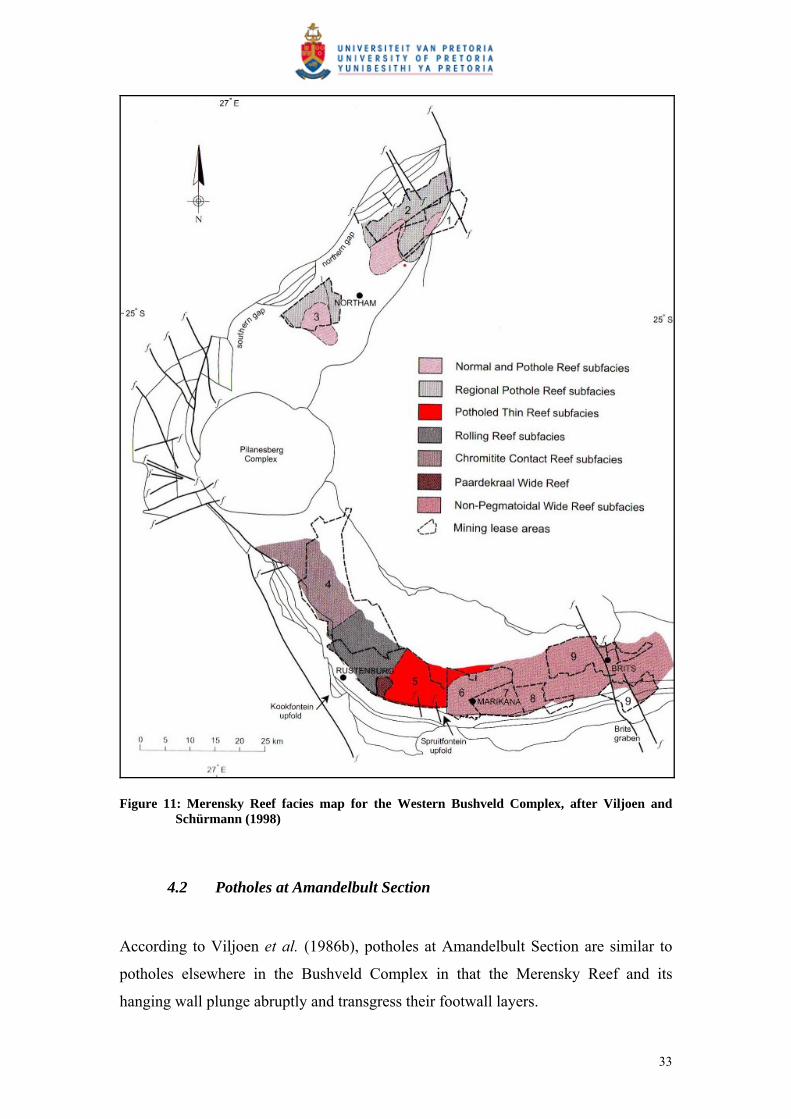
Figure 11: Merensky Reef facies map for the Western Bushveld Complex, after Viljoen and Schürmann (1998)
4.2 Potholes at Amandelbult Section
According to Viljoen et al. (1986b), potholes at Amandelbult Section are similar to
potholes elsewhere in the Bushveld Complex in that the Merensky Reef and its
hanging wall plunge abruptly and transgress their footwall layers.
33
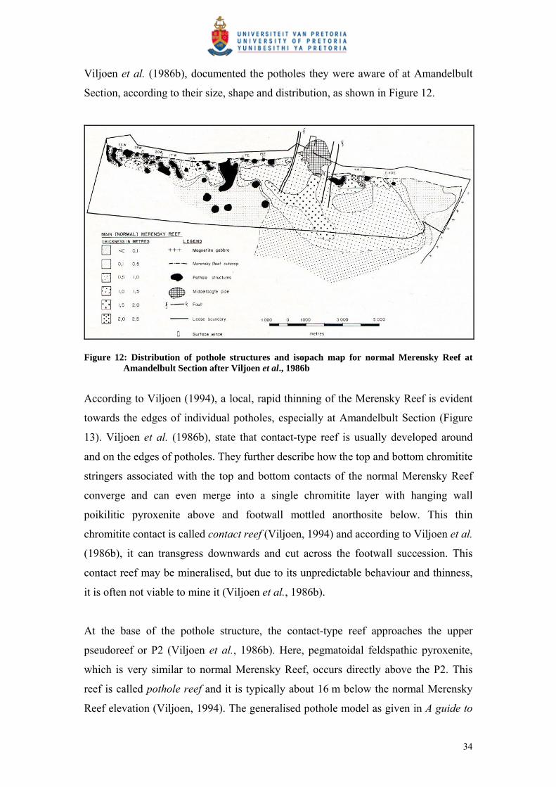
Viljoen et al. (1986b), documented the potholes they were aware of at Amandelbult
Section, according to their size, shape and distribution, as shown in Figure 12.
Figure 12: Distribution of pothole structures and isopach map for normal Merensky Reef at Amandelbult Section after Viljoen et al., 1986b
According to Viljoen (1994), a local, rapid thinning of the Merensky Reef is evident
towards the edges of individual potholes, especially at Amandelbult Section (Figure
13). Viljoen et al. (1986b), state that contact-type reef is usually developed around
and on the edges of potholes. They further describe how the top and bottom chromitite
stringers associated with the top and bottom contacts of the normal Merensky Reef
converge and can even merge into a single chromitite layer with hanging wall
poikilitic pyroxenite above and footwall mottled anorthosite below. This thin
chromitite contact is called contact reef (Viljoen, 1994) and according to Viljoen et al.
(1986b), it can transgress downwards and cut across the footwall succession. This
contact reef may be mineralised, but due to its unpredictable behaviour and thinness,
it is often not viable to mine it (Viljoen et al., 1986b).
At the base of the pothole structure, the contact-type reef approaches the upper
pseudoreef or P2 (Viljoen et al., 1986b). Here, pegmatoidal feldspathic pyroxenite,
which is very similar to normal Merensky Reef, occurs directly above the P2. This
reef is called pothole reef and it is typically about 16 m below the normal Merensky
Reef elevation (Viljoen, 1994). The generalised pothole model as given in A guide to
34

the geology of Amandelbult is shown in Figure 14, where it is also evident that the
footwall of the pothole reef is the feldspathic harzburgite of the P2 as opposed to the
mottled anorthosite of the normal Merensky Reef.
Figure 13: Generalised pothole model for the potholes within the Swartklip facies as developed by Viljoen (1994)
Figure 14: Generalised pothole model for pothole formation at Amandelbult Section from A guide to the geology of Amandelbult
35
4.3 The influence of potholes on mining
4.3.1 Mining of the Merensky Reef at Amandelbult Section
The Merensky Reef topography is initially estimated by extrapolating reef
intersections from deep exploration boreholes. From these boreholes, the general dip
and strike of the ore body is approximated. 3D-Seismic surveys from the surface
provide a more continuous picture of the Merensky Reef and valuable information on
large potholes and structures that could negatively affect the positioning of expensive
capital expenditure such as main and ventilation shafts.
Thin Merensky Reef types are generally mined by narrow (80cm to 100cm)
conventional breast stoping methods (Viljoen, 1994). From deep vertical shafts sunk
through the ore body, haulages are developed parallel to the strike of the reef,
approximately 30 m below it (Figure 15). Horizontal cross-cuts are then developed
towards the dipping reef plane (Figure 16A). Raise lines are excavated in the dip
direction on the reef elevation (Figure 16B). Mining then commences in panels, with
face widths of typically 35 m, from opposite raises (Figure 16C). At the end of the
mining process, a natural dip pillar is left in the middle of the mining block to provide
support.
In the case study presented in this treatise, borehole radar was used to delineate a
mining block bounded by two cross-cuts and a haulage, i.e. a block of approximately
200 m by 200 m.
36

Figure 15: Diagram showing the simplified methodology for conventional breast stoping
Figure 16: The process of mining thin reefs using conventional breast stoping: (A) Cross-cuts are
developed from the haulage to the reef. (B) Raises are developed along the reef elevation. (C) Panels are mined out from opposite raise lines. (D) A dip pillar is left in the middle of the mining block to provide support. (After Du Pisani and Vogt, 2004)
37
4.3.2 Influence of potholes in mining the Merensky Reef at Amandelbult Section
According to Viljoen (1994), for normal Merensky Reef within the Swartklip facies,
which is up to 150 cm thick, the entire reef package is mined together with its
bounding chromitite stringers.
If the reef is thicker than 150 cm, the position of the mining cut is based upon the
vertical grade distribution of the Merensky Reef as described by Viljoen (1994).
Viljoen (1994) states that for the Merensky Reef within the Swartklip facies (thicker
than 150 cm), it is usually the top portion of the reef package that is mined, and that
the bottom pegmatoidal portion and lower chromitite band are left behind.
Potholes in the Swartklip facies are usually identified from local thinning and,
according to Viljoen (1994), the proximity to a pothole can potentially be inferred by
monitoring reef thickness and gradient. As pothole reef typically occurs
approximately 16 m below the normal Merensky Reef elevation (Viljoen, 1994), mine
excavations need to be redeveloped at a lower elevation to access portions of pothole
reef.
Viljoen (1994) advises that an assessment be made of the pothole reef, and the
intermediary contact reef between the normal and pothole reef, before mining
decisions are concluded. He states that due to the irregularity and unpredictable nature
of the contact reef, it is regularly unmineable, and that if a long section of irregular
contact reef is present between the normal and pothole reef, it will lead to a section of
total reef loss.
According to the on-shaft geologist (Marais, pers comm) at the time of the borehole
radar surveys, current practice for predicting potholes is:
Outlines of potholes are based on information gathered from the surface as
well as underground drilling and mapping in stope panels.
When a pothole is intersected in an underground borehole, a fan of boreholes
is drilled in order to determine the extent of the pothole.
38
In ideal situations the miners notify the geologist as soon as they encounter a
pothole in the stope. If a pothole is detected in the stope, the geologist goes to
that working area and tries to map it, and then plots it on to the 1:1000
working plans for that area.
The interpretation of geological structures on the working plans is always a
combination of information from boreholes and underground mapping.
At Amandelbult Section, a pothole is considered significant when it fills up one-third
of a mining panel, i.e. it has a diameter of roughly 10 m to 12 m. According to Marais
(pers comm), miners are supposed to notify the geologist as soon as they intersect a
pothole while stoping. Once the miners have notified the geologist of a pothole
intersection, he will then visit the panel and make a recommendation either to stop the
panel, if the pothole is large enough, or to advance until such a time that the panel
comprises one-third of the total panel length. The geologist’s recommendations are
put in writing and sent to the production manager, section manager, mine overseer and
shift supervisor, as well as the shaft surveyor and shaft rock engineer. Transgression
of the geologist’s recommendations could be liable to disciplinary procedures. Marais
(pers comm) stresses that the above scenario is the ideal situation. He further states
that miners are compensated per square metre advanced and not for ounces of PGE-
minerals delivered to the processing plant, and that in some cases miners will not
disclose that they have encountered a pothole. In such a case, waste material will then
be sent to the plant. Daily reports from the plant will immediately alert managers
when the head grade drops significantly. When this happens, “grade raids” are done
by the surveyors and geologists, during which all stope panels will be visited within
the space of two days to check for off-reef mining.
Marais (pers comm) does, however, say that generally there is good cooperation
between most miners and their line management and that tools such as
photogrammetry (a photographic report of sample sections) could alert the geologist
to the existence of a pothole on a panel. The geologist will then investigate and report
on his findings.
39

The geological losses due to potholes at Amandelbult Section are estimated to be
between 20% and 22% (Marais, pers comm). The term geological losses refers to
areas of the ore body that are unmineable due to geological features such as dykes,
iron-rich ultramafic pegmatites, faults and in this case potholes.
Through cover drilling the geologist can get an idea that mining may be approaching a
pothole, but cover drilling only gives point-information that can make it difficult to
extrapolate pothole boundaries from one borehole to the next. Borehole radar can
provide a continuous illumination line of coordinates highlighting the pothole contact;
that is, if the physical properties of the rocks and survey geometry are optimal.
Through the application of borehole radar it is endeavoured to:
Predict the position of potholes before they are mined into.
Track the thinning of the normal Merensky Reef as it approaches a pothole.
Locate portions of mineable pothole reef.
It must, however, be stressed that borehole radar cannot provide an indication of the
reef grade. It can only delineate the position of the reef more accurately.
5 CASE STUDY
5.1 Introduction
In the Platmine collaborative research programme, the CSIR relies on the
participating mining companies to supply case-study sites for their research. A case-
study site was identified at Anglo Platinum’s Amandelbult Section. The mine
geologist selected an area of the mine where mining had ceased due to a number of
potholes being encountered while mining. The aim of the borehole radar surveys
conducted in four boreholes was to see whether borehole radar could be used to
delineate pothole boundaries. The borehole radar surveys were conducted in
November 2005.
40
5.2 Borehole radar survey design
The survey design was based on delineating a mining block defined by the area
between two cross-cuts (or raise lines) and the haulage from which these cross-cuts
were developed.
A number of survey layouts were considered. The survey layout needed to:
Cover as much of the mining block as possible.
Eliminate the necessity for developing too many cubbies from which to drill
the boreholes required for borehole radar.
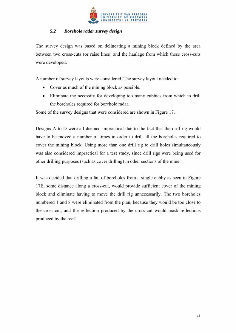
Some of the survey designs that were considered are shown in Figure 17.
Designs A to D were all deemed impractical due to the fact that the drill rig would
have to be moved a number of times in order to drill all the boreholes required to
cover the mining block. Using more than one drill rig to drill holes simultaneously
was also considered impractical for a test study, since drill rigs were being used for
other drilling purposes (such as cover drilling) in other sections of the mine.
It was decided that drilling a fan of boreholes from a single cubby as seen in Figure
17E, some distance along a cross-cut, would provide sufficient cover of the mining
block and eliminate having to move the drill rig unnecessarily. The two boreholes
numbered 1 and 8 were eliminated from the plan, because they would be too close to
the cross-cut, and the reflection produced by the cross-cut would mask reflections
produced by the reef.
41
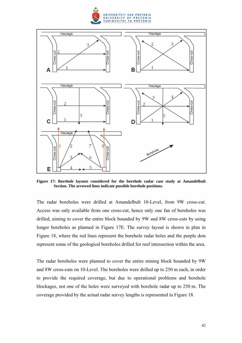
Figure 17: Borehole layouts considered for the borehole radar case study at Amandelbult Section. The arrowed lines indicate possible borehole positions.
The radar boreholes were drilled at Amandelbult 10-Level, from 9W cross-cut.
Access was only available from one cross-cut, hence only one fan of boreholes was
drilled, aiming to cover the entire block bounded by 9W and 8W cross-cuts by using
longer boreholes as planned in Figure 17E. The survey layout is shown in plan in
Figure 18, where the red lines represent the borehole radar holes and the purple dots
represent some of the geological boreholes drilled for reef intersection within the area.
The radar boreholes were planned to cover the entire mining block bounded by 9W
and 8W cross-cuts on 10-Level. The boreholes were drilled up to 250 m each, in order
to provide the required coverage, but due to operational problems and borehole
blockages, not one of the holes were surveyed with borehole radar up to 250 m. The
coverage provided by the actual radar survey lengths is represented in Figure 18.
42

In Figure 19, a map is presented that shows the location of the boreholes drilled for
borehole radar in relation to all the geological boreholes drilled for reef intersection in
the vicinity of the borehole radar survey area.
Figure 18: Simplified mine plan showing the positions of the four boreholes drilled for borehole radar as red lines and the location of geological reef intersect boreholes
43

Figure 19: The location of the borehole radar holes in relation to some of the geological drilling in the vicinity
44

The boreholes were drilled in the norite between the Merensky and Bastard reefs (see
the stratigraphic column in Figure 9). As described in Section 3, the bottom contacts
of both the Merensky and Bastard reefs are expected to produce radar reflections.
The boreholes were angled away from the Merensky Reef and towards the Bastard
Reef so that these two reflectors could be distinguishable on the radargrams. A
radargram acquired for borehole 1 is shown in Figure 20A to demonstrate how the
two radar reflectors produced by the Merensky and Bastard reefs could be
distinguished from one another. At the collar of borehole 1, it is close to the Merensky
Reef and far from the Bastard Reef. As we progress along the borehole, the borehole
moves further away from the Merensky Reef and closer to the Bastard Reef. Hence,
the Merensky Reef reflector on the radargram starts close to the borehole position at
0m along the x-axis, and moves further away from the borehole position as we
progress along the borehole. The Bastard Reef reflector starts far from the borehole
position at its collar and moves closer to the borehole. Both reflectors manifest within
the two-dimensional space of the radargram as a function of their distance away from
the borehole.
Figure 20B provides a schematic showing the positions of the Bastard and Merensky
reefs above and below the borehole respectively.
45

Figure 20: A) Radargram for borehole 1 showing how the Merensky and Bastard Reef reflectors plot at similar distances away from the borehole position; and
B) Schematic showing the Bastard Reef position above the borehole and the Merensky Reef below the borehole.
The basic planned case-study layout is shown in section in Figure 21. The boreholes
are indicated by slanted red lines. In Figure 22, the positions of the radar boreholes are
shown in section in the software package that was used to conduct the borehole radar
modelling. Both Figure 21 and Figure 22 show the planned borehole positions prior to
conducting the surveys and radar modelling. In reality, some boreholes started much
closer to the Merensky Reef and in some cases the boreholes even started inside the
Merensky Reef unit.
The boreholes could not be drilled below the Merensky Reef due to access problems
and due to the presence of the very conductive harzburgite layer, the P2, through
which radar waves are generally not able to penetrate, as discussed in Section 3. The
boreholes were numbered by the drilling contractor from north to south in the
46

following order: BH4, BH2, BH1 and BH3 (where BH is an abbreviation for
“borehole”).
The drilling inclination and radar survey length for each borehole is summarised in
Table 2.
Table 2: Borehole information for the radar boreholes
Borehole Inclination Radar survey length (m)
BH4 + 16 ° 132
BH2 + 6 ° 132
BH1 - 7 ° 147
BH3 - 12 ° 200
These boreholes were drilled specifically for the application of borehole radar surveys
and according to recommendations from the CSIR, namely:
The boreholes were drilled sub-parallel to the expected Merensky Reef plane.
The boreholes were close enough to the Merensky Reef so that radar waves
could reach it, i.e. within 30 m.
The boreholes were not drilled to provide Merensky Reef intersection for
grade information.
47
Not according to scale
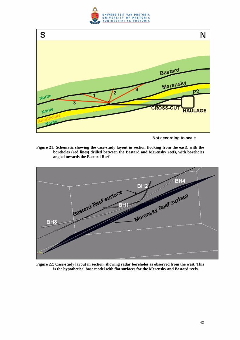
Figure 21: Schematic showing the case-study layout in section (looking from the east), with the boreholes (red lines) drilled between the Bastard and Merensky reefs, with boreholes angled towards the Bastard Reef
Figure 22: Case-study layout in section, showing radar boreholes as observed from the west. This
is the hypothetical base model with flat surfaces for the Merensky and Bastard reefs.
48

5.3 Borehole radar results
5.3.1 Methodology
The borehole radar results are given and discussed from north to south. After data
acquisition, the radar data were processed using band-pass and automatic gain control
filters. The band-pass filter eliminated all frequencies not within the range of the
Aardwolf borehole radar. Two-dimensional radargrams are presented for all four
holes, without interpretation and with the interpreted reflectors indicated.
After the initial processing, all the radar data, together with the individual directional
surveys, were imported into Fresco, an open-source 3D visualisation program
developed under the Platmine collaborative research programme. Fresco uses forward
modelling to aide the interpreter to visualise reflective planes in relation to the
borehole radar holes. Radar illumination lines were produced along these reflective
surfaces, which were then exported as XYZ coordinates and used together with other
borehole information to construct a surface for the Merensky Reef below the borehole
radar boreholes.
This methodology is explained in more detail during the discussion for borehole 4,
and the same technique was used to interpret the results for the other three boreholes.
5.3.2 Borehole 4
Borehole radar data were collected for 132 m along borehole 4. The directional survey
and geological log for borehole 4 are given in Appendix 1. The radargram for
borehole 4 is shown in Figure 23, with and without interpretation. Good radar data
were acquired up to approximately 96 m along the borehole. The loss of signal
between 96 m and 110 m is visible on both the in- and out-surveys. This loss of signal
is typical for what is expected when conductive water pools in the borehole, because
radar waves generally do not penetrate through very conductive water. This borehole
is, however, drilled at an upward angle, i.e. no water is expected inside the borehole.
49
The geological log for borehole 4 (Appendix 1) shows that iron-replacement was
logged in the borehole between 97.4 m and 97.87 m and then again between 103.34 m
and 106.56 m. Iron-replacement is very conductive, and it would explain the signal
loss seen on the radargram.
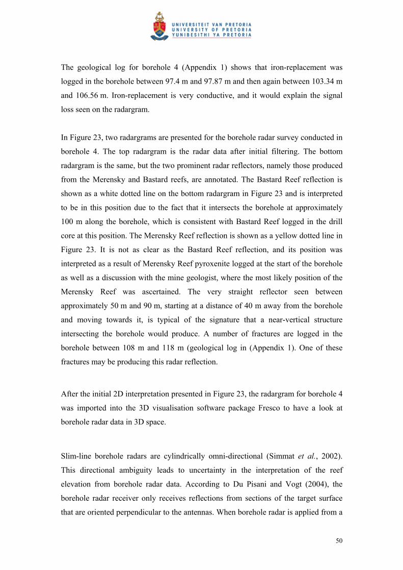
In Figure 23, two radargrams are presented for the borehole radar survey conducted in
borehole 4. The top radargram is the radar data after initial filtering. The bottom
radargram is the same, but the two prominent radar reflectors, namely those produced
from the Merensky and Bastard reefs, are annotated. The Bastard Reef reflection is
shown as a white dotted line on the bottom radargram in Figure 23 and is interpreted
to be in this position due to the fact that it intersects the borehole at approximately
100 m along the borehole, which is consistent with Bastard Reef logged in the drill
core at this position. The Merensky Reef reflection is shown as a yellow dotted line in
Figure 23. It is not as clear as the Bastard Reef reflection, and its position was
interpreted as a result of Merensky Reef pyroxenite logged at the start of the borehole
as well as a discussion with the mine geologist, where the most likely position of the
Merensky Reef was ascertained. The very straight reflector seen between
approximately 50 m and 90 m, starting at a distance of 40 m away from the borehole
and moving towards it, is typical of the signature that a near-vertical structure
intersecting the borehole would produce. A number of fractures are logged in the
borehole between 108 m and 118 m (geological log in (Appendix 1). One of these
fractures may be producing this radar reflection.
After the initial 2D interpretation presented in Figure 23, the radargram for borehole 4
was imported into the 3D visualisation software package Fresco to have a look at
borehole radar data in 3D space.
Slim-line borehole radars are cylindrically omni-directional (Simmat et al., 2002).
This directional ambiguity leads to uncertainty in the interpretation of the reef
elevation from borehole radar data. According to Du Pisani and Vogt (2004), the
borehole radar receiver only receives reflections from sections of the target surface
that are oriented perpendicular to the antennas. When borehole radar is applied from a
50

borehole drilled parallel to the reef horizon, it maps a single illumination line along
the reef surface (Du Pisani and Vogt, 2004). One way to resolve the directional
ambiguity is through the use of a priori information. The regional dip and strike of the
ore body are known, and can be used as a first approximation of the position of the
reflector. The drill core of the radar borehole is used to orient the borehole within the
local stratigraphy; hence it can be determined whether reflections originate above or
below the borehole. Furthermore, any other a priori geological information is used to
improve the interpretation and resolve directional ambiguity. Geological intersections
from other boreholes within the borehole radar survey area, as well as reef pegs from
mining in the immediate vicinity, are used to get a better picture of the reef surface.
The radargram for borehole 4 was imported into Fresco together with the borehole’s
trajectory survey. In this way the curvature of the borehole is taken into consideration,
and the interpreter is forced to consider the geometry of the borehole in relation to
possible reflectors. In Fresco a candidate ore body can be manipulated, and its radar
response can be modelled in real time. The model can then be manipulated until its
response agrees with the measured response. The forward modelling approach has
three advantages:
It avoids the need for migration of the radar data. When borehole radar data is
migrated, it must take into account the curvature of the borehole, which requires
an assumption about the direction to various targets.
Borehole data remains inherently ambiguous in azimuth. The 3D forward
modelling environment forces the interpreter to constantly confront the
ambiguity, ensuring that the output is a product of the interpreter’s understanding
of the problem and not simply automatically generated.
The position of the illumination line on the target is produced directly in 3D
space. This is the required product from a borehole radar survey, and is difficult
to produce using other techniques.
As seen in Figure 24, candidate surfaces were constructed for the Bastard and
Merensky reefs above and below borehole 4. In the three-dimensional modelling for
all four boreholes, the Bastard Reef surface is red and the Merensky Reef surface is
51
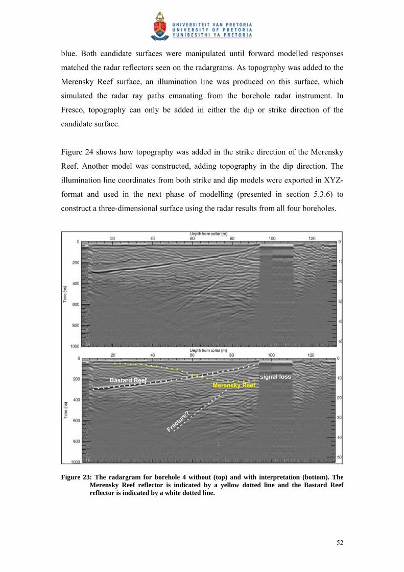
blue. Both candidate surfaces were manipulated until forward modelled responses
matched the radar reflectors seen on the radargrams. As topography was added to the
Merensky Reef surface, an illumination line was produced on this surface, which
simulated the radar ray paths emanating from the borehole radar instrument. In
Fresco, topography can only be added in either the dip or strike direction of the
candidate surface.
Figure 24 shows how topography was added in the strike direction of the Merensky
Reef. Another model was constructed, adding topography in the dip direction. The
illumination line coordinates from both strike and dip models were exported in XYZ-
format and used in the next phase of modelling (presented in section 5.3.6) to
construct a three-dimensional surface using the radar results from all four boreholes.
Figure 23: The radargram for borehole 4 without (top) and with interpretation (bottom). The Merensky Reef reflector is indicated by a yellow dotted line and the Bastard Reef reflector is indicated by a white dotted line.
52
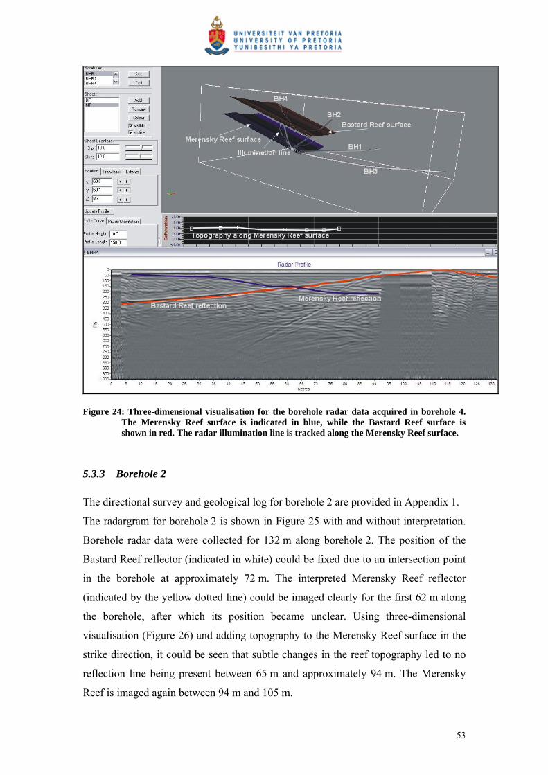
Figure 24: Three-dimensional visualisation for the borehole radar data acquired in borehole 4. The Merensky Reef surface is indicated in blue, while the Bastard Reef surface is shown in red. The radar illumination line is tracked along the Merensky Reef surface.
5.3.3 Borehole 2
The directional survey and geological log for borehole 2 are provided in Appendix 1.
The radargram for borehole 2 is shown in Figure 25 with and without interpretation.
Borehole radar data were collected for 132 m along borehole 2. The position of the
Bastard Reef reflector (indicated in white) could be fixed due to an intersection point
in the borehole at approximately 72 m. The interpreted Merensky Reef reflector
(indicated by the yellow dotted line) could be imaged clearly for the first 62 m along
the borehole, after which its position became unclear. Using three-dimensional
visualisation (Figure 26) and adding topography to the Merensky Reef surface in the
strike direction, it could be seen that subtle changes in the reef topography led to no
reflection line being present between 65 m and approximately 94 m. The Merensky
Reef is imaged again between 94 m and 105 m.
53
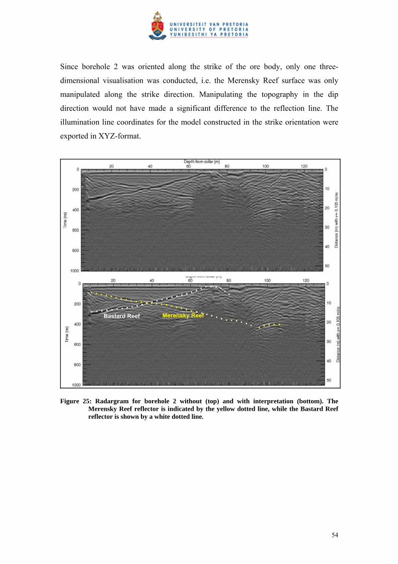
Since borehole 2 was oriented along the strike of the ore body, only one three-
dimensional visualisation was conducted, i.e. the Merensky Reef surface was only
manipulated along the strike direction. Manipulating the topography in the dip
direction would not have made a significant difference to the reflection line. The
illumination line coordinates for the model constructed in the strike orientation were
exported in XYZ-format.
Figure 25: Radargram for borehole 2 without (top) and with interpretation (bottom). The Merensky Reef reflector is indicated by the yellow dotted line, while the Bastard Reef reflector is shown by a white dotted line.
54
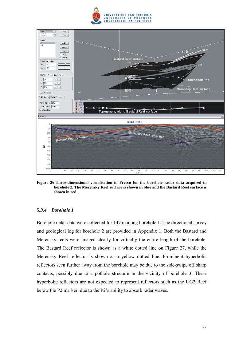
Figure 26:Three-dimensional visualisation in Fresco for the borehole radar data acquired in borehole 2. The Merensky Reef surface is shown in blue and the Bastard Reef surface is shown in red.
5.3.4 Borehole 1
Borehole radar data were collected for 147 m along borehole 1. The directional survey
and geological log for borehole 2 are provided in Appendix 1. Both the Bastard and
Merensky reefs were imaged clearly for virtually the entire length of the borehole.
The Bastard Reef reflector is shown as a white dotted line on Figure 27, while the
Merensky Reef reflector is shown as a yellow dotted line. Prominent hyperbolic
reflectors seen further away from the borehole may be due to the side-swipe off sharp
contacts, possibly due to a pothole structure in the vicinity of borehole 3. These
hyperbolic reflectors are not expected to represent reflectors such as the UG2 Reef
below the P2 marker, due to the P2’s ability to absorb radar waves.
55
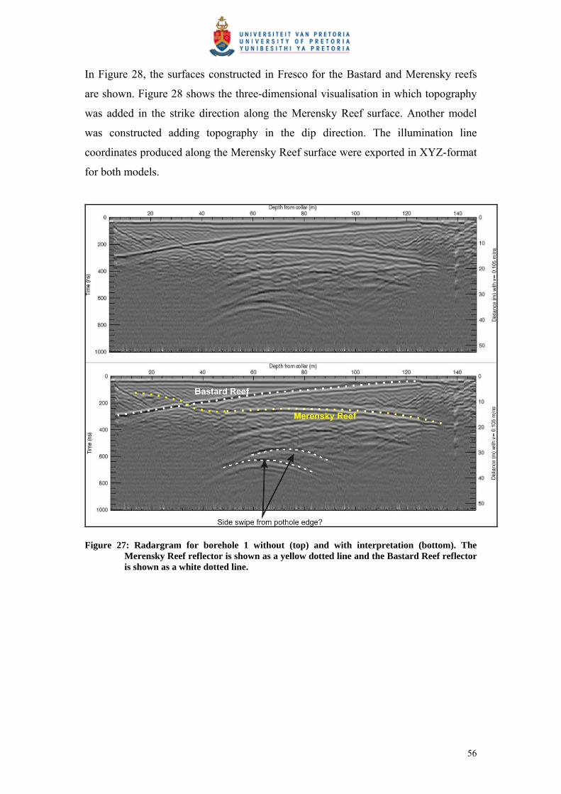
In Figure 28, the surfaces constructed in Fresco for the Bastard and Merensky reefs
are shown. Figure 28 shows the three-dimensional visualisation in which topography
was added in the strike direction along the Merensky Reef surface. Another model
was constructed adding topography in the dip direction. The illumination line
coordinates produced along the Merensky Reef surface were exported in XYZ-format
for both models.
Figure 27: Radargram for borehole 1 without (top) and with interpretation (bottom). The Merensky Reef reflector is shown as a yellow dotted line and the Bastard Reef reflector is shown as a white dotted line.
56

Figure 28: Three-dimensional visualisation for borehole radar data acquired in borehole 1. The Merensky Reef surface is shown in red and the Bastard Reef surface is shown in blue.
5.3.5 Borehole 3
Borehole radar data were collected for 200 m along borehole 3 (Figure 29). The
directional survey and geological log for borehole 3 are provided in Appendix 1.
The Bastard Reef reflector (shown in white) can clearly be seen between 0 m and
116 m, after which it intersects the borehole. The Merensky Reef reflector is not very
clear on the radargram for borehole 3, but there are sections of a reflector between
0 m and 136 m that correspond to where the Merensky Reef reflector is expected as a
result of the three-dimensional visualisation done in the previous three boreholes. The
inferred position of the Merensky Reef reflector is shown as a yellow dotted line in
Figure 29. Another steeply dipping reflector (represented by the dashed white line in
Figure 29), can be seen between 0 m and 80 m on the radargram. This reflector may
be due to a dyke in the vicinity of the boreholes.
57

The Merensky Reef surface produced in Fresco is shown in blue in Figure 30. The
visualisation where topography was manipulated in the dip direction is shown here.
The illumination line coordinates produced by visualisation in the dip and strike
directions were exported in XYZ-format and used for further modelling.
Figure 29: Radargram for borehole 3 without (top) and with interpretation (bottom). The interpreted Merensky Reef reflector is shown as a yellow dotted line and the Bastard Reef reflector is shown as a white dotted line.
58

Figure 30: Three-dimensional visualisation for borehole radar data acquired in borehole 3. The Merensky Reef reflector is shown as a blue surface.
5.3.6 Contouring of geological and borehole radar illumination line coordinates
Two contour maps were produced to show the increase in data density if borehole
radar is applied. In Figure 31, the contours that were produced by gridding the
Merensky Reef intersection coordinates in the geological boreholes in the vicinity of
the borehole radar boreholes is presented. Figure 32 shows the contours produced by
gridding the illumination line coordinates produced for the Merensky Reef by
conducting borehole radar in the four boreholes. It can be observed that more
information is available for interrogation after borehole radar was applied. There is
much more geological detail to be seen for the Merensky Reef in the area where
borehole radar was conducted.
59
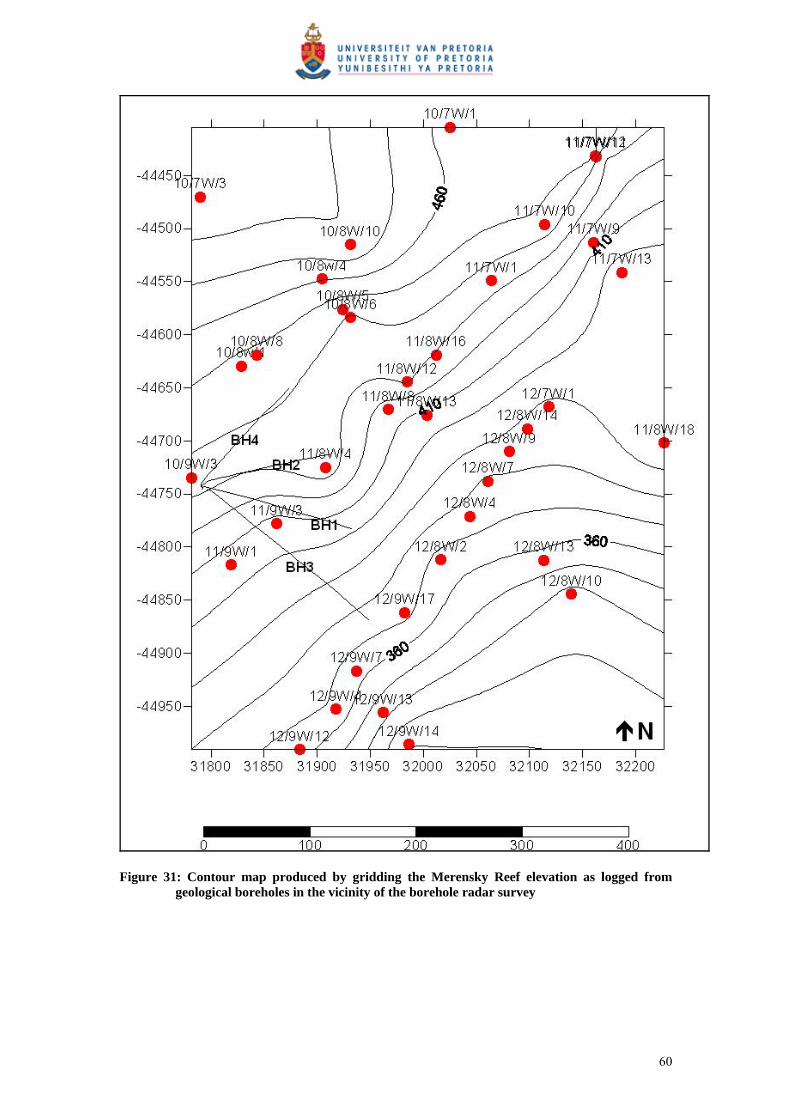
Figure 31: Contour map produced by gridding the Merensky Reef elevation as logged from geological boreholes in the vicinity of the borehole radar survey
60
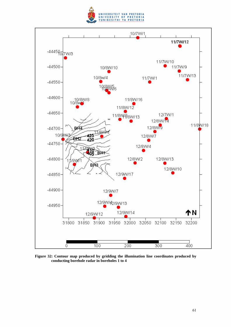
Figure 32: Contour map produced by gridding the illumination line coordinates produced by conducting borehole radar in boreholes 1 to 4
61
5.3.7 Three-dimensional surface (all boreholes)
The illumination lines produced by all the three-dimensional visualisations done for
boreholes 1 to 4 were used, together with some Merensky Reef intersections from
geological boreholes in the borehole radar block, to produce a three-dimensional
surface. All the illumination line coordinates used for this study are presented in
Appendix B.
In Figure 33A, the surface constructed by using only the Merensky Reef intersection
from geological boreholes is shown in grey (Surface A). The positions of the
geological boreholes are indicated as red dots.
The surface produced by gridding the XYZ-coordinates of all the illumination lines is
shown in blue (Surface B). In Figure 33A, it can be observed that Surface B slumps
below Surface A, indicating that the borehole radar results show that there is a pothole
structure in the west of the mining block that would not have been detected if only the
reef intersections from the geological boreholes had been used. Only the portion of
the slumped Surface B that differs significantly (more that 1 m) is defined as the
pothole in Figure 34.
This pothole (annotated in Figure 34) has an elliptical shape that is approximately
50 m across and slumps approximately 5 m, which would have significant
implications for the mining of this block. The financial implication of mining into this
pothole is discussed in the cost-benefit analysis conducted in Section 6.
Furthermore, the upward slope of the illumination line for borehole 4 indicates that
the reef may be rolling upwards in the north of the block defined by borehole radar.
This information may also be useful when this block is eventually mined, both
financially and from a safety point of view.
62
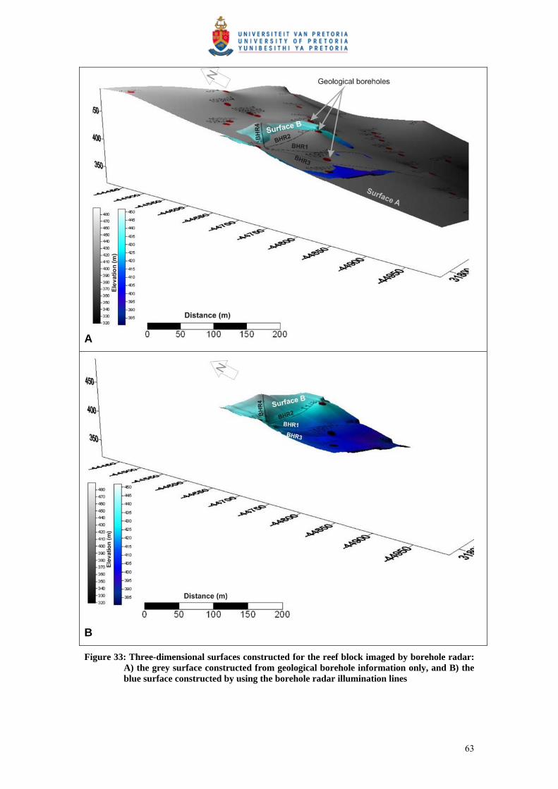
A
B
Figure 33: Three-dimensional surfaces constructed for the reef block imaged by borehole radar: A) the grey surface constructed from geological borehole information only, and B) the blue surface constructed by using the borehole radar illumination lines
63

Figure 34: The surface produced by gridding the XYZ-coordinates from the borehole radar modelling, with the positions of the imaged pothole indicated
64

6 COST-BENEFIT ANALYSIS
6.1 Introduction
Advance knowledge of the reef topography ahead of mining should lead to increased
profitability to the mine as a result of reducing the geological risk associated with
features such as potholes, faulting, dykes and reef replacement due to iron-rich
ultramafic pegmatites (IRUPs). Safety issues associated with the aforementioned
geological features can also be negated if the features are known before they are
encountered.
Currently, information about the reef is obtained through surface and cover drilling
and mapping the reef surface while developing raises and stopes. Both drilling and
excavating tunnels are expensive practices. Any way to reduce unnecessary drilling
and/or development would imply a cost saving to the mine. The cost-benefit analysis
described in this section aims to prove that the use of borehole radar can minimise
wasted development and improve efficiencies throughout the mining cycle.
While exploiting an ore body there are various phases through which the mining cycle
progresses, namely:
Ore body definition.
Mine design.
Development.
Extraction.
Processing.
The effect of applying borehole radar is described in the following sub-sections as it
relates to each of the abovementioned mining stages. Where possible, an attempt is
made to quantify the cost benefit that borehole radar provides.
65
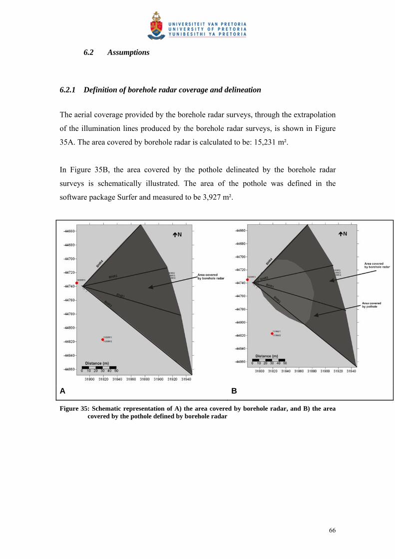
6.2 Assumptions
6.2.1 Definition of borehole radar coverage and delineation
The aerial coverage provided by the borehole radar surveys, through the extrapolation
of the illumination lines produced by the borehole radar surveys, is shown in Figure
35A. The area covered by borehole radar is calculated to be: 15,231 m².
In Figure 35B, the area covered by the pothole delineated by the borehole radar
surveys is schematically illustrated. The area of the pothole was defined in the
software package Surfer and measured to be 3,927 m².
A B
Figure 35: Schematic representation of A) the area covered by borehole radar, and B) the area covered by the pothole defined by borehole radar
66

6.2.2 Values used in cost-benefit analysis
6.2.2.1 Platinum Price The daily London platinum prices for 2006 are shown in Figure 36.
The average platinum price for 2006, as defined in Platinum 2007, is used:
US$1,141.84
Figure 36: Daily platinum prices in 2006, given in US$, after Platinum 2007
6.2.2.2 Platinum grade As stated earlier in this treatise, a fixed platinum grade is used for all the financial
calculations in this treatise. The platinum grade used for the Merensky Reef at
Amandelbult is 6.26 g/t. (Anglo Platinum Annual Report 2006).
For this treatise only the platinum values are used for calculation. The other PGE-
metals are not considered.
6.2.2.3 Rand/dollar exchange rate The average monthly rand/US dollar currency rates for 2006 as provided by
www.gocurrency.com are shown in Figure 37.
The exchange rate used in this treatise is the annual average: 6.73.
67
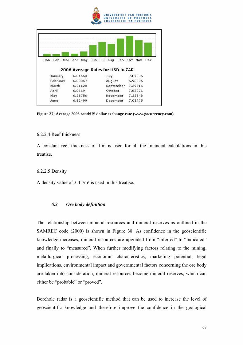
Figure 37: Average 2006 rand/US dollar exchange rate (www.gocurrency.com)
6.2.2.4 Reef thickness A constant reef thickness of 1 m is used for all the financial calculations in this
treatise.
6.2.2.5 Density A density value of 3.4 t/m³ is used in this treatise.
6.3 Ore body definition
The relationship between mineral resources and mineral reserves as outlined in the
SAMREC code (2000) is shown in Figure 38. As confidence in the geoscientific
knowledge increases, mineral resources are upgraded from “inferred” to “indicated”
and finally to “measured”. When further modifying factors relating to the mining,
metallurgical processing, economic characteristics, marketing potential, legal
implications, environmental impact and governmental factors concerning the ore body
are taken into consideration, mineral resources become mineral reserves, which can
either be “probable” or “proved”.
Borehole radar is a geoscientific method that can be used to increase the level of
geoscientific knowledge and therefore improve the confidence in the geological
68

model. Borehole radar can be used in the process of converting resources to reserves
or it can upgrade the status of either of these two classifications.
Figure 38: Mineral reserves and resources according to the SAMREC code (2000)
6.3.1 Geological drilling
The case study in Section 5 of this treatise describes how borehole radar was used to
image the Merensky Reef within a mining block at Amandelbult Section. Prior to
conducting borehole radar, 10 vertical geological boreholes were drilled within the
block covered by the borehole radar survey. The positions of these boreholes are
given in Figure 39. Due to the complexity of the reef topography in this part of the
mine, a number of holes were drilled from similar positions in order to get clarity on
how the reef topography was changing. In Figure 39, it can be observed how
geological boreholes 11/8W1, 11/8W2, 11/8W3, 11/8W4 and 11/8W5 were drilled
within 5 m of each other in order to determine the position of the Merensky Reef. The
boreholes located along the straight line running from south-west to north-east were
drilled upwards from development on the next lower level (11-Level).
69
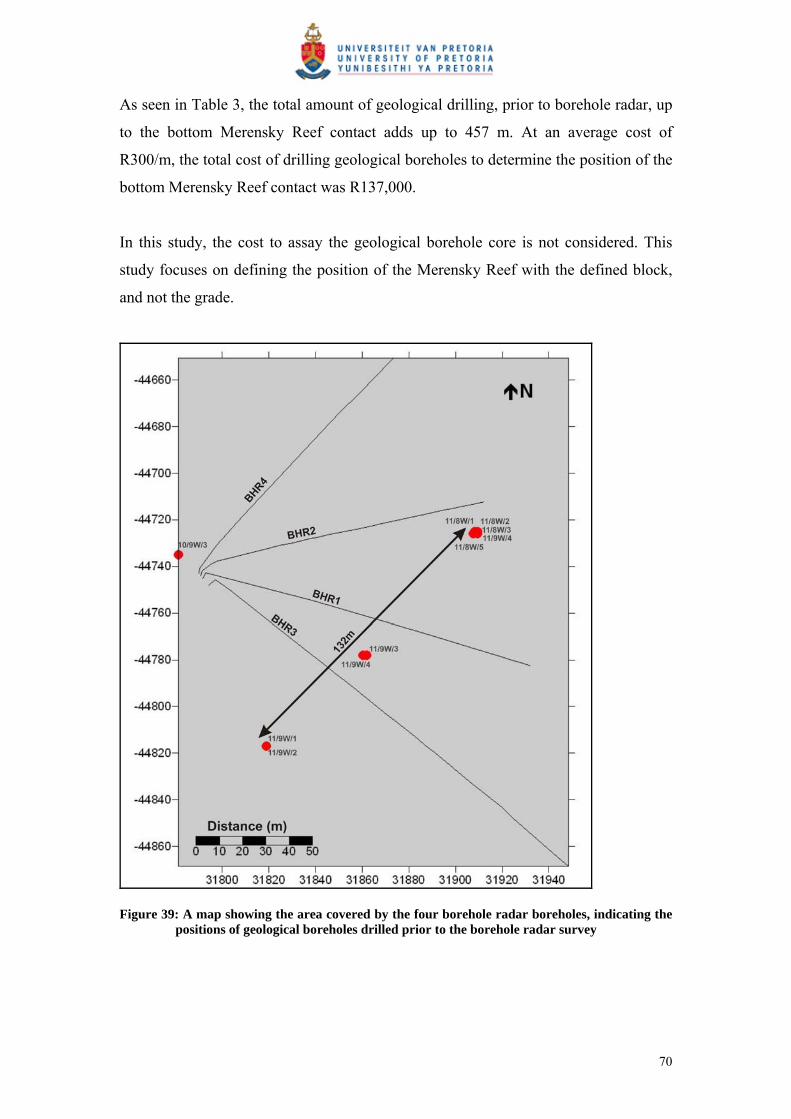
As seen in Table 3, the total amount of geological drilling, prior to borehole radar, up
to the bottom Merensky Reef contact adds up to 457 m. At an average cost of
R300/m, the total cost of drilling geological boreholes to determine the position of the
bottom Merensky Reef contact was R137,000.
In this study, the cost to assay the geological borehole core is not considered. This
study focuses on defining the position of the Merensky Reef with the defined block,
and not the grade.
Figure 39: A map showing the area covered by the four borehole radar boreholes, indicating the positions of geological boreholes drilled prior to the borehole radar survey
70
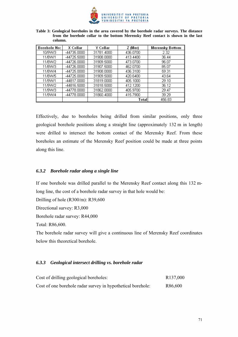
Table 3: Geological boreholes in the area covered by the borehole radar surveys. The distance from the borehole collar to the bottom Merensky Reef contact is shown in the last column.
Effectively, due to boreholes being drilled from similar positions, only three
geological borehole positions along a straight line (approximately 132 m in length)
were drilled to intersect the bottom contact of the Merensky Reef. From these
boreholes an estimate of the Merensky Reef position could be made at three points
along this line.
6.3.2 Borehole radar along a single line
If one borehole was drilled parallel to the Merensky Reef contact along this 132 m-
long line, the cost of a borehole radar survey in that hole would be:
Drilling of hole (R300/m): R39,600
Directional survey: R3,000
Borehole radar survey: R44,000
Total: R86,600.
The borehole radar survey will give a continuous line of Merensky Reef coordinates
below this theoretical borehole.
6.3.3 Geological intersect drilling vs. borehole radar
Cost of drilling geological boreholes: R137,000
Cost of one borehole radar survey in hypothetical borehole: R86,600
71
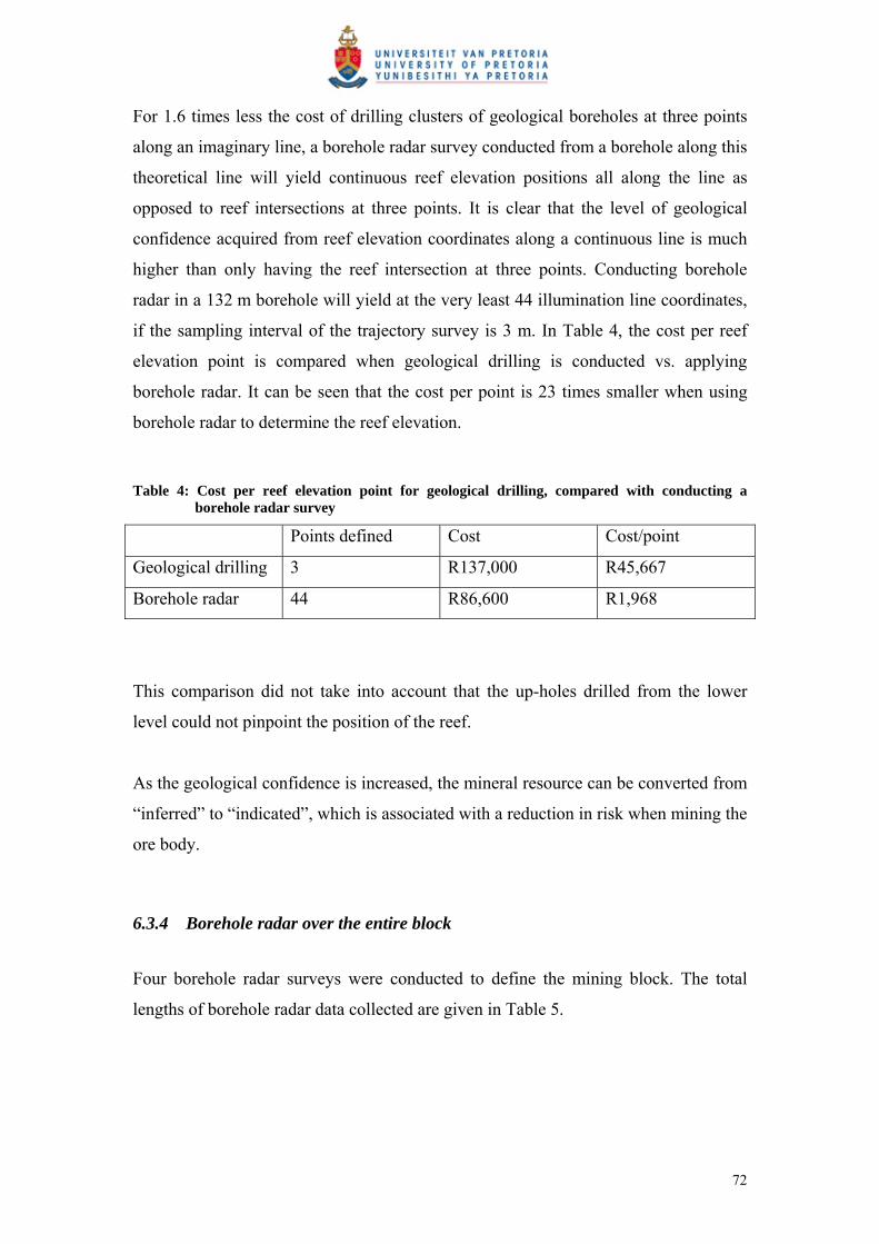
For 1.6 times less the cost of drilling clusters of geological boreholes at three points
along an imaginary line, a borehole radar survey conducted from a borehole along this
theoretical line will yield continuous reef elevation positions all along the line as
opposed to reef intersections at three points. It is clear that the level of geological
confidence acquired from reef elevation coordinates along a continuous line is much
higher than only having the reef intersection at three points. Conducting borehole
radar in a 132 m borehole will yield at the very least 44 illumination line coordinates,
if the sampling interval of the trajectory survey is 3 m. In Table 4, the cost per reef
elevation point is compared when geological drilling is conducted vs. applying
borehole radar. It can be seen that the cost per point is 23 times smaller when using
borehole radar to determine the reef elevation.
Table 4: Cost per reef elevation point for geological drilling, compared with conducting a borehole radar survey
Points defined Cost Cost/point
Geological drilling 3 R137,000 R45,667
Borehole radar 44 R86,600 R1,968
This comparison did not take into account that the up-holes drilled from the lower
level could not pinpoint the position of the reef.
As the geological confidence is increased, the mineral resource can be converted from
“inferred” to “indicated”, which is associated with a reduction in risk when mining the
ore body.
6.3.4 Borehole radar over the entire block
Four borehole radar surveys were conducted to define the mining block. The total
lengths of borehole radar data collected are given in Table 5.
72

Table 5: Survey lengths for all four radar boreholes
Borehole Length (m)
BHR1 147
BHR2 132
BHR3 200
BHR4 132
Total 611
The total cost of drilling 611 m for the borehole radar holes at a cost of R300/m is
R183,300.
The total cost of applying borehole radar at commercial rates (November 2005) when
all four surveys are completed during one week, i.e. mobilisation to Amandelbult,
approximately 430 km from Johannesburg takes place only once: R185,000 (including
VAT).
Furthermore, directional surveys at an estimated cost of R3,000 per survey are
required in order to interpret the borehole radar data.
The total cost of borehole radar:
Drilling: R183,300
Borehole radar: R185,000
Directional surveys: R12,000
Total cost: R380,300
From Section 6.1.1, the cost of drilling geological boreholes within the survey area:
R137,000.
Although applying borehole radar in the area was approximately 2.8 times more
expensive than all the geological drilling done in the same area, the coverage gained
by the borehole radar survey is approximately 15,231 m², as opposed to only three
points/intersections spaced approximately 60 m apart along a 132 m straight line.
73
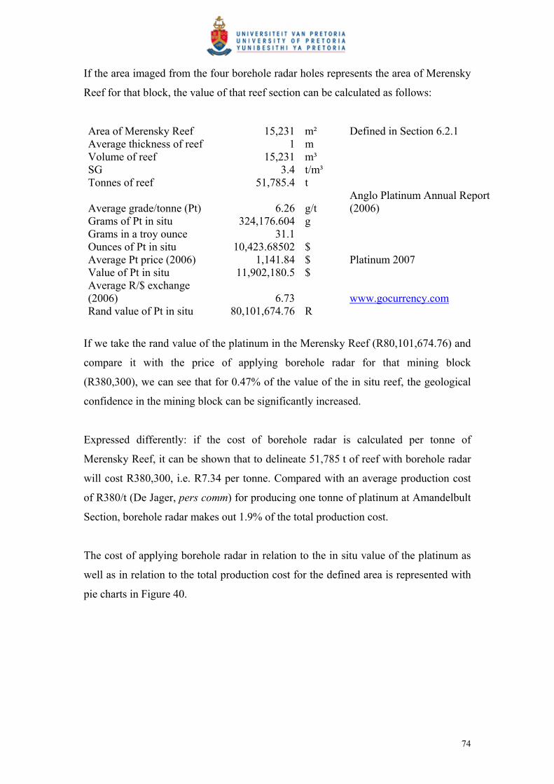
If the area imaged from the four borehole radar holes represents the area of Merensky
Reef for that block, the value of that reef section can be calculated as follows:
Area of Merensky Reef 15,231 m² Defined in Section 6.2.1 Average thickness of reef 1 m Volume of reef 15,231 m³ SG 3.4 t/m³ Tonnes of reef 51,785.4 t
Average grade/tonne (Pt) 6.26 g/t Anglo Platinum Annual Report (2006)
Grams of Pt in situ 324,176.604 g Grams in a troy ounce 31.1 Ounces of Pt in situ 10,423.68502 $ Average Pt price (2006) 1,141.84 $ Platinum 2007 Value of Pt in situ 11,902,180.5 $ Average R/$ exchange (2006) 6.73 www.gocurrency.com Rand value of Pt in situ 80,101,674.76 R
If we take the rand value of the platinum in the Merensky Reef (R80,101,674.76) and
compare it with the price of applying borehole radar for that mining block
(R380,300), we can see that for 0.47% of the value of the in situ reef, the geological
confidence in the mining block can be significantly increased.
Expressed differently: if the cost of borehole radar is calculated per tonne of
Merensky Reef, it can be shown that to delineate 51,785 t of reef with borehole radar
will cost R380,300, i.e. R7.34 per tonne. Compared with an average production cost
of R380/t (De Jager, pers comm) for producing one tonne of platinum at Amandelbult
Section, borehole radar makes out 1.9% of the total production cost.
The cost of applying borehole radar in relation to the in situ value of the platinum as
well as in relation to the total production cost for the defined area is represented with
pie charts in Figure 40.
74

Value of Pt
Cost of BHR
Production cost
Cost of BHR
A B
Figure 40: Cost of borehole radar compared with A) the value of the in situ platinum in block delineated by borehole radar and B) the production cost per tonne of platinum
6.3.5 Geostatistical increase in confidence
It was attempted to define the increase in confidence levels for the elevation of the
Merensky Reef in the mining block by conducting geostatistical calculations for two
scenarios within the Amandelbult mining block.
These scenarios were:
Using only the available geological drill holes within the block.
Using the illumination line coordinates from the borehole radar surveys
conducted within the block.
6.3.5.1 Scenario 1
Confidence in the reef elevation within the mining block using only the initial
geological boreholes
In Scenario 1, 10 geological drill holes were available for geostatistical analysis. The
parameter analysed was the elevation (z) of the Merensky Reef measured in metres.
The position of these geological drill holes are shown in Figure 17.
Using the software program Geoeas, standard statistical parameters were calculated:
n: 10 (number of points)
Mean ( g ): 428 m
Median: 418.5 m
75
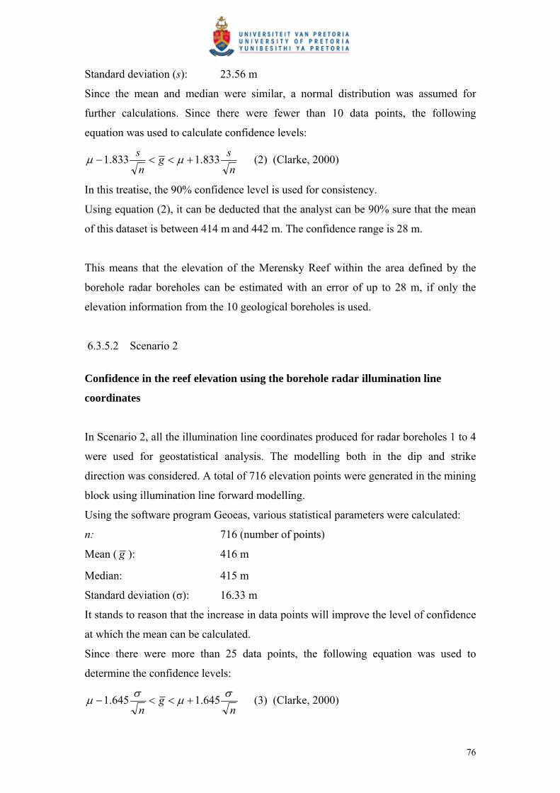
Standard deviation (s): 23.56 m
Since the mean and median were similar, a normal distribution was assumed for
further calculations. Since there were fewer than 10 data points, the following
equation was used to calculate confidence levels:
n
sg
n
s833.1833.1 (2) (Clarke, 2000)
In this treatise, the 90% confidence level is used for consistency.
Using equation (2), it can be deducted that the analyst can be 90% sure that the mean
of this dataset is between 414 m and 442 m. The confidence range is 28 m.
This means that the elevation of the Merensky Reef within the area defined by the
borehole radar boreholes can be estimated with an error of up to 28 m, if only the
elevation information from the 10 geological boreholes is used.
6.3.5.2 Scenario 2
Confidence in the reef elevation using the borehole radar illumination line
coordinates
In Scenario 2, all the illumination line coordinates produced for radar boreholes 1 to 4
were used for geostatistical analysis. The modelling both in the dip and strike
direction was considered. A total of 716 elevation points were generated in the mining
block using illumination line forward modelling.
Using the software program Geoeas, various statistical parameters were calculated:
n: 716 (number of points)
Mean ( g ): 416 m
Median: 415 m
Standard deviation (σ): 16.33 m
It stands to reason that the increase in data points will improve the level of confidence
at which the mean can be calculated.
Since there were more than 25 data points, the following equation was used to
determine the confidence levels:
ng
n
645.1645.1 (3) (Clarke, 2000)
76

Using equation (3), it follows that the analyst can be 90% sure that the mean of this
dataset is between 415 m and 417 m, i.e. the confidence range is 2 m.
This means that the elevation of the Merensky Reef can be estimated at a much higher
accuracy than using only the geological drilling within the mining block. The
confidence range has improved from 28 m to 2 m, a 14-fold improvement.
Therefore, if borehole radar is used to delineate a mining block, the reef elevation can
be determined with much more confidence than relying on geological borehole
intersections alone.
6.3.5.3 Discussion
Using basic geostatistical equations, it can be concluded that the application of
borehole radar in the mining block has significantly improved the level of confidence
in the position of the Merensky Reef.
Stated differently, to achieve the same level of confidence as provided by borehole
radar, 716 vertical geological boreholes would have been required.
The average length of the geological boreholes used in the mining block to intersect
the Merensky Reef was 46 m (using values in Table 3). If 716 of these boreholes were
drilled at a drilling cost of R300/m, the total cost would be 716 x 46 x 300m =
R9,880,800.
The same level of confidence was achieved with four borehole radar surveys at a cost
of R380,300, i.e. 3.84% of the cost of drilling 716 geological boreholes.
6.4 Mine design
Mine design and mine development are very closely related. In this section it is shown
that the area that is to be developed is sampled better if borehole radar is applied prior
to development as opposed to only using geological boreholes to fix the position of
77
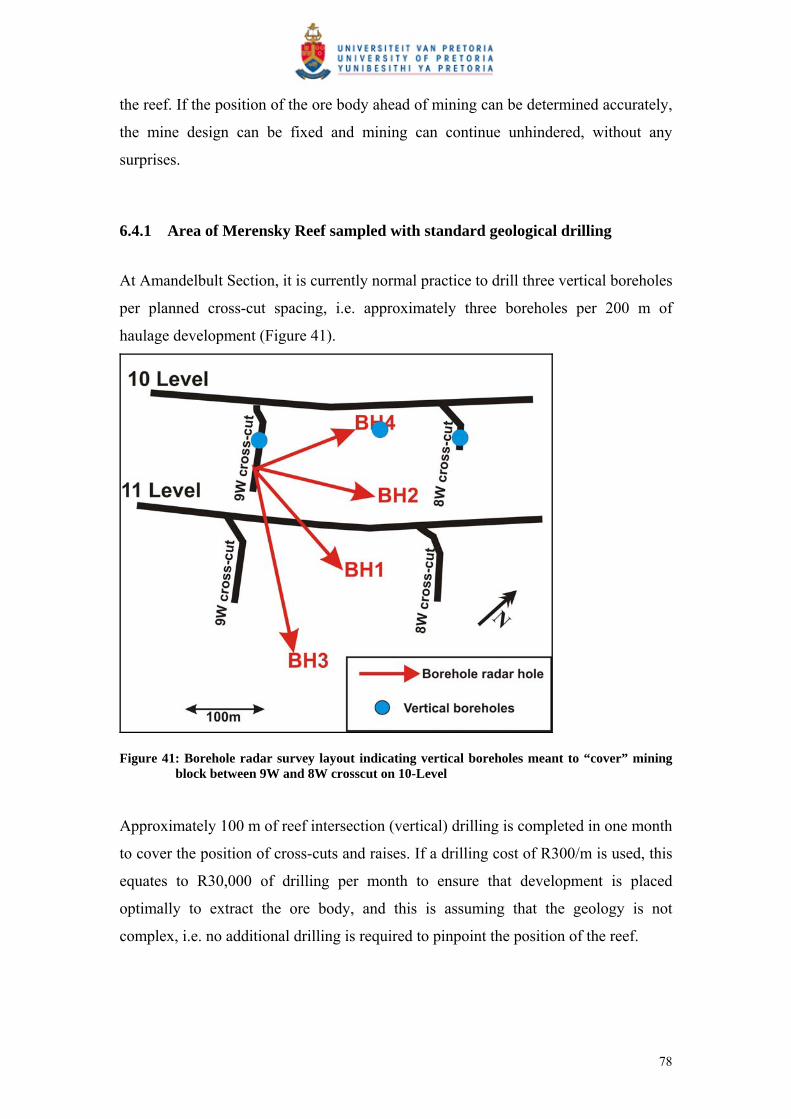
the reef. If the position of the ore body ahead of mining can be determined accurately,
the mine design can be fixed and mining can continue unhindered, without any
surprises.
6.4.1 Area of Merensky Reef sampled with standard geological drilling
At Amandelbult Section, it is currently normal practice to drill three vertical boreholes
per planned cross-cut spacing, i.e. approximately three boreholes per 200 m of
haulage development (Figure 41).
Figure 41: Borehole radar survey layout indicating vertical boreholes meant to “cover” mining block between 9W and 8W crosscut on 10-Level
Approximately 100 m of reef intersection (vertical) drilling is completed in one month
to cover the position of cross-cuts and raises. If a drilling cost of R300/m is used, this
equates to R30,000 of drilling per month to ensure that development is placed
optimally to extract the ore body, and this is assuming that the geology is not
complex, i.e. no additional drilling is required to pinpoint the position of the reef.
78

For R30,000 three pierce points through the Merensky Reef are obtained along a
200 m line defined by the haulage position.
The mine planner can now be confident that the position of the Merensky Reef is
fixed where the boreholes pierce the reef. Exploratory underground geological
boreholes are drilled with AXT drill bits. These drill bits have a diameter of 48 mm
(Heinz, 1994). Since these are vertical up-holes, they intersect the reef plane with a
circular shape, i.e. the positions of three circular pieces of reef within the reef plane
are known. The area of each piece is:
A = π r² = π (0.024)² = 0.0018 m²
Area of Merensky Reef sampled: 0.0054 m² (3 x AXT size boreholes)
6.4.2 Area of Merensky Reef sampled using borehole radar
The horizontal resolution of a radar instrument is defined by the size of its first
Fresnel zone (Vogt, 2003). The radius of the first Fresnel zone is defined by the
distance of the radar antenna from the target horizon as seen in Figure 42.
Figure 42: The first Fresnel zone (Vogt 2003)
Radar information about the reflective surface is gathered from an area below the
boreholes of the Amandelbult case study as defined by the following equation:
79

20 4
1 rRF (4) (Vogt, 2003)
Equation (4) defines the radius of the first Fresnel zone.
The areas from which radar data are gathered for each of the Amandelbult radar
boreholes are shown in Figure 43. This figure shows that borehole radar effectively
samples 474 m² + 528 m² + 528 m² + 800 m² = 2,330 m² of the mining block.
Figure 43: The areas from which borehole radar data is gathered for boreholes 1 to 4
80
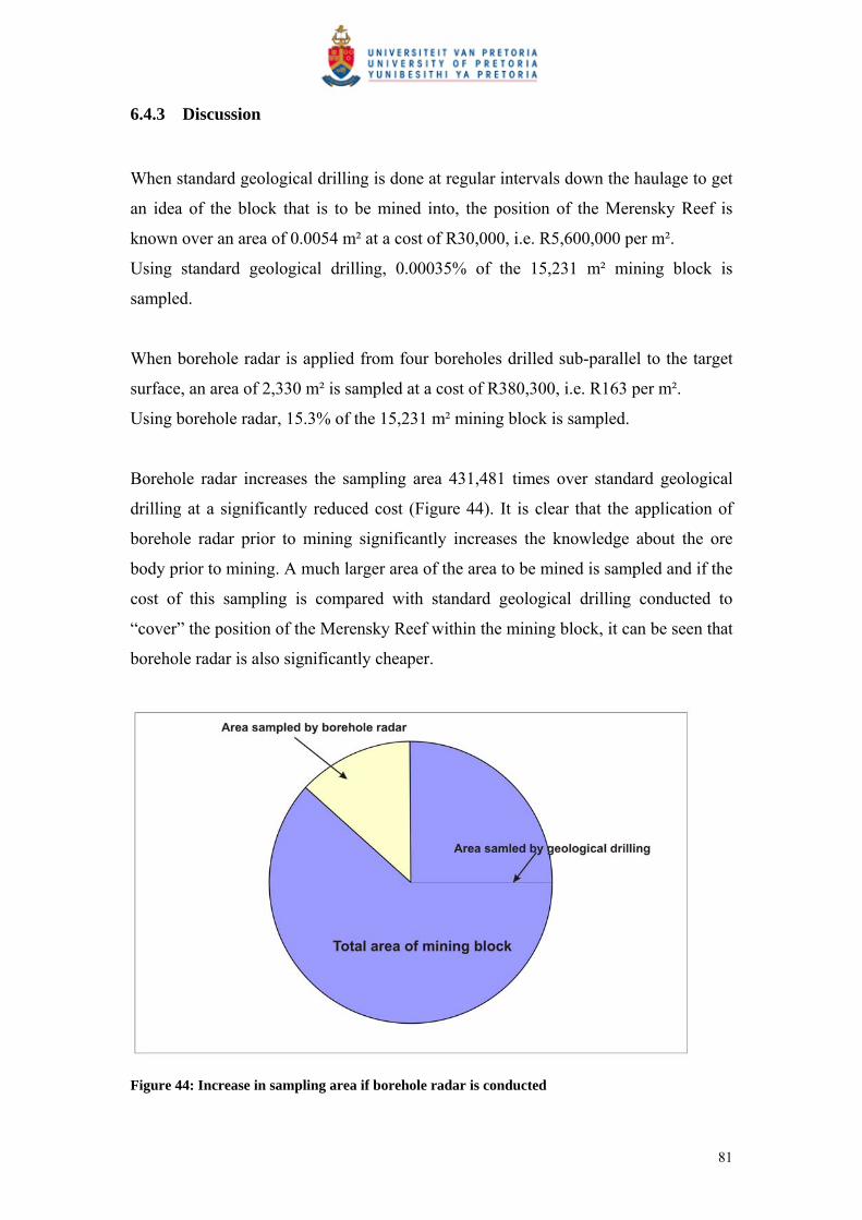
6.4.3 Discussion
When standard geological drilling is done at regular intervals down the haulage to get
an idea of the block that is to be mined into, the position of the Merensky Reef is
known over an area of 0.0054 m² at a cost of R30,000, i.e. R5,600,000 per m².
Using standard geological drilling, 0.00035% of the 15,231 m² mining block is
sampled.
When borehole radar is applied from four boreholes drilled sub-parallel to the target
surface, an area of 2,330 m² is sampled at a cost of R380,300, i.e. R163 per m².
Using borehole radar, 15.3% of the 15,231 m² mining block is sampled.
Borehole radar increases the sampling area 431,481 times over standard geological
drilling at a significantly reduced cost (Figure 44). It is clear that the application of
borehole radar prior to mining significantly increases the knowledge about the ore
body prior to mining. A much larger area of the area to be mined is sampled and if the
cost of this sampling is compared with standard geological drilling conducted to
“cover” the position of the Merensky Reef within the mining block, it can be seen that
borehole radar is also significantly cheaper.
Figure 44: Increase in sampling area if borehole radar is conducted
81
6.5 Development
The conventional mining layout is used at Amandelbult Section (shown in Figure 15).
Development takes place in three ways:
1. Secondary development
Footwall haulages, developed on strike at a constant distance below the reef
plane.
Cross-cuts, developed horizontally to intersect the reef plane.
2. Primary development
Raises developed in the reef plane.
3. Ancillary development
Other development such as travelling ways, ore passes, timber pays, drilling
cubbies et cetera.
In Section 4.3.2 (Figure 16), the conventional mining progression within a mining
block is described. From opposite raise lines, mining proceeds in panels until a natural
dip pillar is left for support in the centre of the block.
Once the raises have been developed, the reef between two neighbouring raises is
extracted or stoped. Mine development is expressed as a ratio called the m²/m ratio,
where:
The m² refers to the area of reef that is available for mining after the necessary
development is done, and the m refers to the development required to provide access
to the reef.
The m²/m ratio is affected by various factors, such as the geometry of the reef, the dip
and structural complexity of the reef as well as the mining efficiencies achieved when
extracting the reef. According to De Jager (pers comm), the m²/m ratio should
theoretically be in the vicinity of 50 m²/m, but due to the factors listed above, typical
values range between of 20 m²/m and 25 m²/m.
The m²/m ratio for the mining block imaged by borehole radar is calculated below.
82

Let’s assume the area of reef available for mining is 15,231 m², i.e. we take the same
amount of reef available for mining as imaged by borehole radar described in Section
6.2.1 (Figure 35).
If the m²/m ratio is taken as 25, then 609 m of development was required to make this
reef available.
This case study described in Section 3 shows that borehole radar imaged a pothole in
the Merensky Reef. This pothole is an elliptical feature with a long axis of
approximately 100 m, a short axis of approximately 50 m and a slump of
approximately 5 m. Due to the size of the slump, this elliptical area defined by the
pothole is not available for mining. The area of the pothole was calculated in the
mapping software as 3,927 m².
The total area available for mining is now 15,231 m² – 3,927 m² = 11,304 m².
If the presence of the pothole was unknown (i.e. borehole radar had not been applied),
then the same amount of development would have taken place, i.e. 609 m.
The m²/m ratio would then have been 11,304/609 = 18.56 m²/m, i.e. with the same
amount of development, 6.4 m² less would have been available for mining.
Converted to monetary values:
83
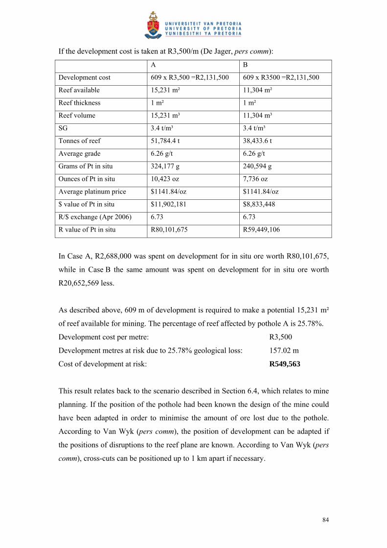
If the development cost is taken at R3,500/m (De Jager, pers comm):
A B
Development cost 609 x R3,500 =R2,131,500 609 x R3500 =R2,131,500
Reef available 15,231 m² 11,304 m²
Reef thickness 1 m² 1 m²
Reef volume 15,231 m³ 11,304 m³
SG 3.4 t/m³ 3.4 t/m³
Tonnes of reef 51,784.4 t 38,433.6 t
Average grade 6.26 g/t 6.26 g/t
Grams of Pt in situ 324,177 g 240,594 g
Ounces of Pt in situ 10,423 oz 7,736 oz
Average platinum price $1141.84/oz $1141.84/oz
$ value of Pt in situ $11,902,181 $8,833,448
R/$ exchange (Apr 2006) 6.73 6.73
R value of Pt in situ R80,101,675 R59,449,106
In Case A, R2,688,000 was spent on development for in situ ore worth R80,101,675,
while in Case B the same amount was spent on development for in situ ore worth
R20,652,569 less.
As described above, 609 m of development is required to make a potential 15,231 m²
of reef available for mining. The percentage of reef affected by pothole A is 25.78%.
Development cost per metre: R3,500
Development metres at risk due to 25.78% geological loss: 157.02 m
Cost of development at risk: R549,563
This result relates back to the scenario described in Section 6.4, which relates to mine
planning. If the position of the pothole had been known the design of the mine could
have been adapted in order to minimise the amount of ore lost due to the pothole.
According to Van Wyk (pers comm), the position of development can be adapted if
the positions of disruptions to the reef plane are known. According to Van Wyk (pers
comm), cross-cuts can be positioned up to 1 km apart if necessary.
84
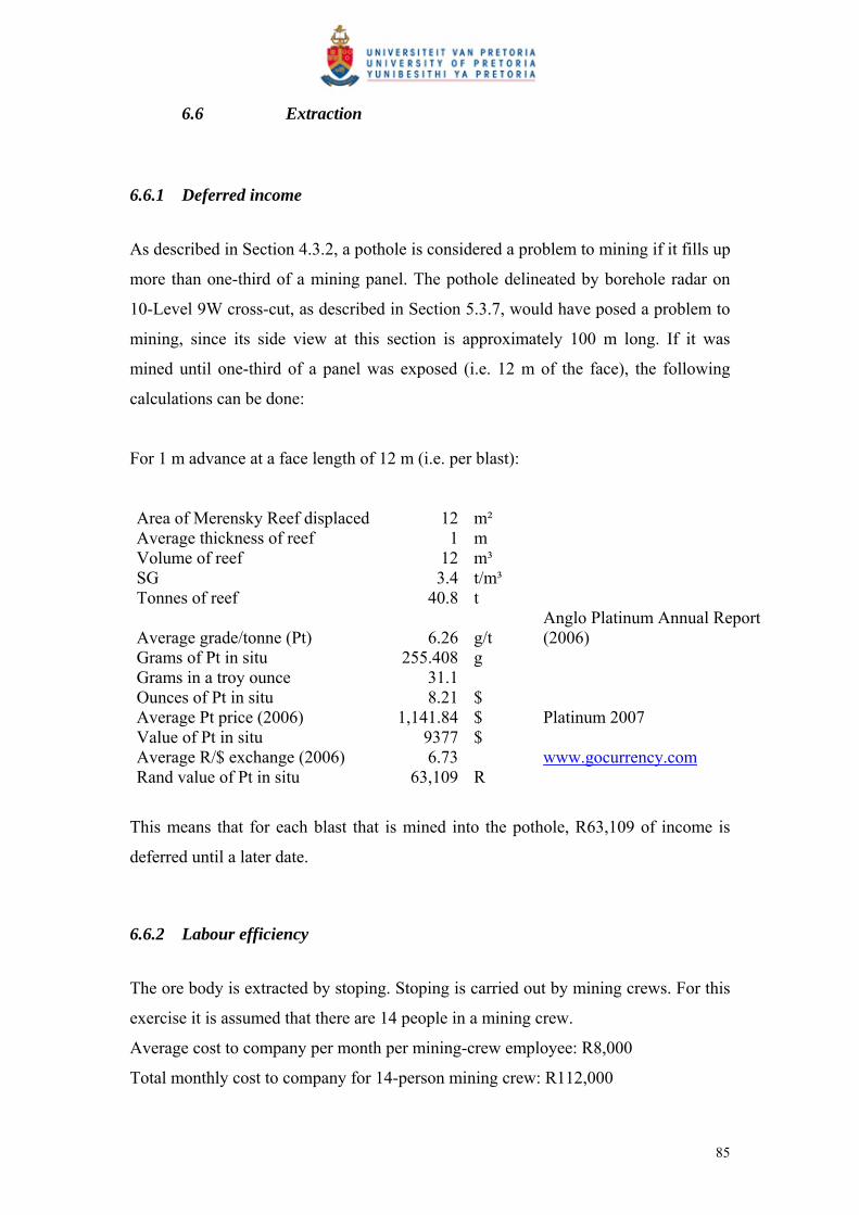
6.6 Extraction
6.6.1 Deferred income
As described in Section 4.3.2, a pothole is considered a problem to mining if it fills up
more than one-third of a mining panel. The pothole delineated by borehole radar on
10-Level 9W cross-cut, as described in Section 5.3.7, would have posed a problem to
mining, since its side view at this section is approximately 100 m long. If it was
mined until one-third of a panel was exposed (i.e. 12 m of the face), the following
calculations can be done:
For 1 m advance at a face length of 12 m (i.e. per blast):
Area of Merensky Reef displaced 12 m² Average thickness of reef 1 m Volume of reef 12 m³ SG 3.4 t/m³ Tonnes of reef 40.8 t
Average grade/tonne (Pt) 6.26 g/t Anglo Platinum Annual Report (2006)
Grams of Pt in situ 255.408 g Grams in a troy ounce 31.1 Ounces of Pt in situ 8.21 $ Average Pt price (2006) 1,141.84 $ Platinum 2007 Value of Pt in situ 9377 $ Average R/$ exchange (2006) 6.73 www.gocurrency.com Rand value of Pt in situ 63,109 R
This means that for each blast that is mined into the pothole, R63,109 of income is
deferred until a later date.
6.6.2 Labour efficiency
The ore body is extracted by stoping. Stoping is carried out by mining crews. For this
exercise it is assumed that there are 14 people in a mining crew.
Average cost to company per month per mining-crew employee: R8,000
Total monthly cost to company for 14-person mining crew: R112,000
85
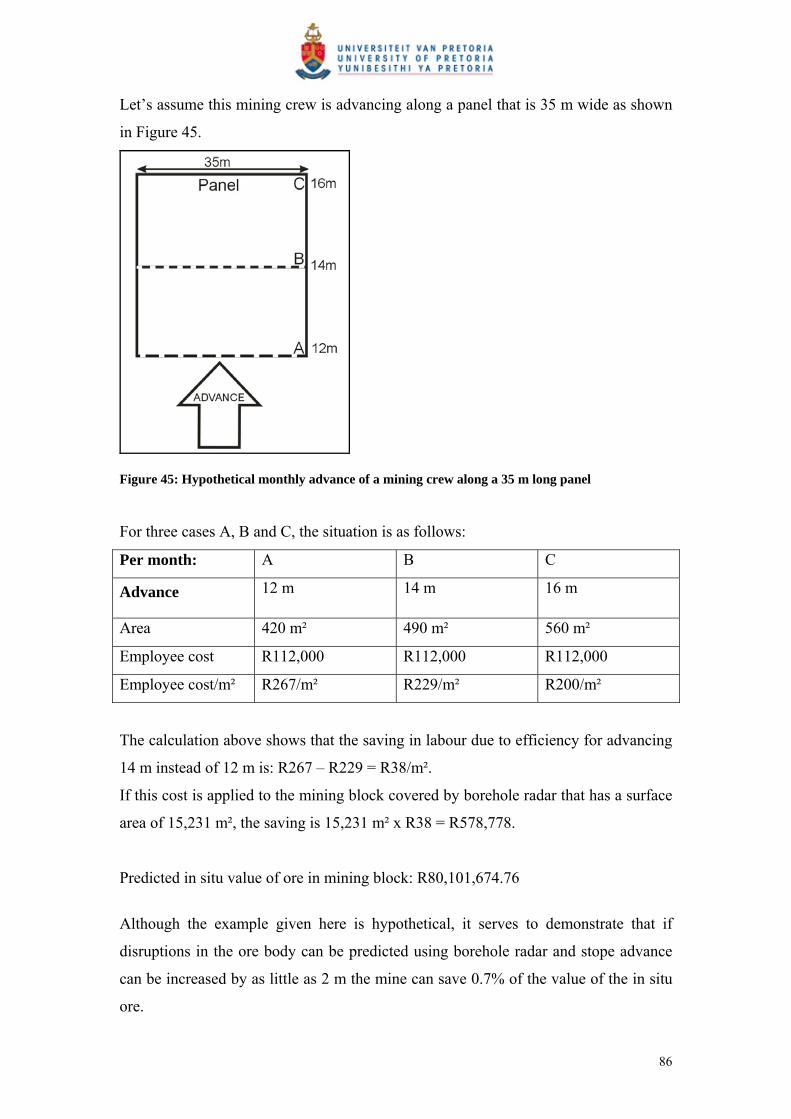
Let’s assume this mining crew is advancing along a panel that is 35 m wide as shown
in Figure 45.
Figure 45: Hypothetical monthly advance of a mining crew along a 35 m long panel
For three cases A, B and C, the situation is as follows:
Per month: A B C
Advance 12 m 14 m 16 m
Area 420 m² 490 m² 560 m²
Employee cost R112,000 R112,000 R112,000
Employee cost/m² R267/m² R229/m² R200/m²
The calculation above shows that the saving in labour due to efficiency for advancing
14 m instead of 12 m is: R267 – R229 = R38/m².
If this cost is applied to the mining block covered by borehole radar that has a surface
area of 15,231 m², the saving is 15,231 m² x R38 = R578,778.
Predicted in situ value of ore in mining block: R80,101,674.76
Although the example given here is hypothetical, it serves to demonstrate that if
disruptions in the ore body can be predicted using borehole radar and stope advance
can be increased by as little as 2 m the mine can save 0.7% of the value of the in situ
ore.
86

The result is that mining crews can be used more efficiently, and unnecessary
development into waste rock can be prevented.
6.7 Processing
The processing of the ore extracted is directly affected by the presence of waste
material. The ore is effectively diluted and waste material that displaces ore in the mill
will lead to inefficiencies and a loss of revenue.
In this example it is assumed that the pothole material is mined through and reports to
ore in the plant, i.e. it is not detected as waste material. According to Marais (pers
comm), this scenario will most likely be prevented by daily monitoring of the plant
head-grade, but another reason why this calculation is of importance is that if the
pothole is mined through in the hope that reef will be encountered, the result is
“deferred income”, i.e. waste is being mined as ore and income that would have been
derived from ore is being postponed until a later date.
Tonnes covered by mining block described in Section 6.5: 51,784 t
Tonnes of waste due to pothole A: 13,350 t
Cost per tonne (shaft head + overheads + concentrator): R380
Mining cost of waste tonnes mined as ore: R5,073,000
The loss of revenue due to mining through the pothole can be calculated as follows:
Tonnes milled from mining block described in Section 6.5: 51,784 t
Planned contained Pt at 6.26g/t: 10,423 ounces
Actual contained Pt (diluted 25.78%): 7,736 ounces
Lost Pt: 2,687 ounces
Lost revenue at $1,141.84/oz and exchange rate of 6.73: R20,648,475
If the loss of revenue for one mining block is R20,648,475, the impact on the entire
mine where waste is mined instead of ore due to unpredicted geological losses will be
significant.
87

7 CONCLUSIONS AND RECOMMENDATIONS
7.1 Conclusions
This project aimed to provide clear evidence that incorporating borehole radar in the
mining cycle will provide significant cost benefit in the long term.
This study has shown that the application of borehole radar prior to mining:
Provides more geological information about the reef prior to mining than relying
only on geological intersection of the reef.
Can provide continuous reef coordinates along the illumination line, as opposed
to the point intersections provided by geological cover drilling.
Significantly improves the confidence in the elevation of the Merensky Reef
within the mining block.
Samples a much larger portion of the reef to be extracted than standard geological
drilling at a significantly reduced cost.
Improves mine planning and ensures that mine development is put in the correct
place.
Avoids unnecessary mine development.
Can ensure that mining teams are deployed more effectively in areas where reef
has been defined by borehole radar.
Can prevent sending waste to the plant instead of ore.
Can avoid deferring income until a later date.
The findings that were calculated in the previous sections are summarised in Table 6.
Results are given for the scenario where only geological drilling would have been
used to make mining decisions about the defined mining block, as opposed to the
situation after borehole radar was applied. The broad impact of borehole radar at the
various mining cycles is shown in Table 7.
88
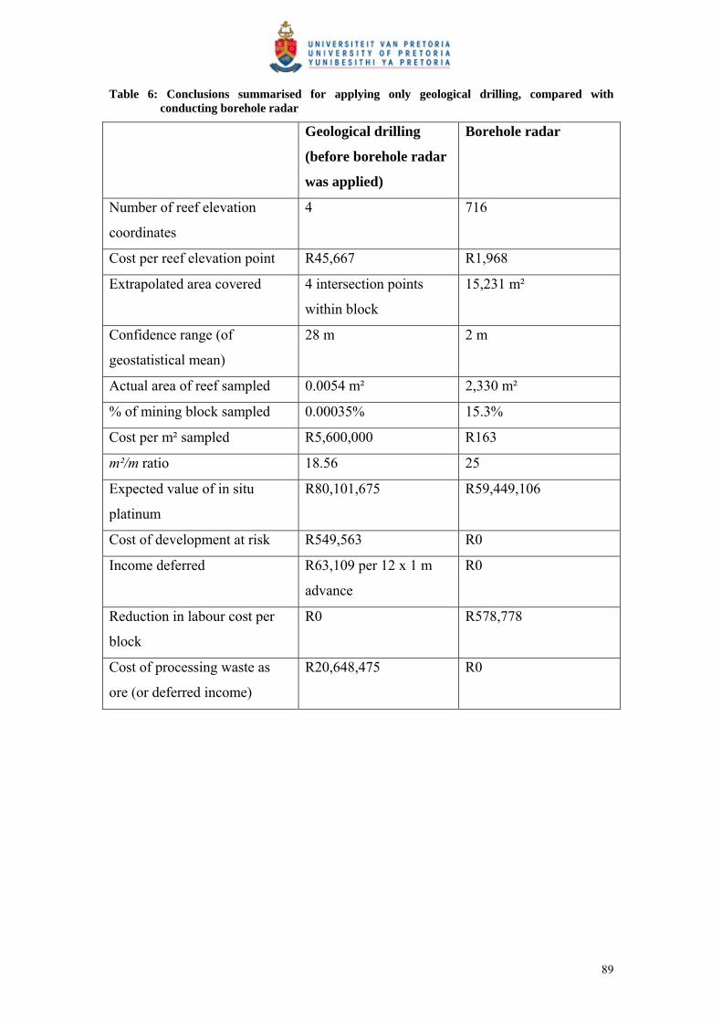
Table 6: Conclusions summarised for applying only geological drilling, compared with conducting borehole radar
Geological drilling
(before borehole radar
was applied)
Borehole radar
Number of reef elevation
coordinates
4 716
Cost per reef elevation point R45,667 R1,968
Extrapolated area covered 4 intersection points
within block
15,231 m²
Confidence range (of
geostatistical mean)
28 m 2 m
Actual area of reef sampled 0.0054 m² 2,330 m²
% of mining block sampled 0.00035% 15.3%
Cost per m² sampled R5,600,000 R163
m²/m ratio 18.56 25
Expected value of in situ
platinum
R80,101,675 R59,449,106
Cost of development at risk R549,563 R0
Income deferred R63,109 per 12 x 1 m
advance
R0
Reduction in labour cost per
block
R0 R578,778
Cost of processing waste as
ore (or deferred income)
R20,648,475 R0
89

Table 7: The impact of borehole radar at the five stages of mining an ore body
Mining stage Impact of borehole radar
1. Ore body definition Increased knowledge leads to improved reserve
definition and improved confidence
2. Mine design Improved mine planning
3. Development Improvement in m²/m ratio
4. Extraction Improved planning and improvement of
efficiencies
5. Processing Dilution lowered and better recoveries
7.2 Recommendations
It is recommended that:
The borehole radar interpretation made in this treatise be reconciled with the
actual situation once the area discussed is mined.
Further work is done in order to determine how the mine layout can be
optimised in order to accommodate operational borehole radar surveys.
The impact of borehole radar on mine design is investigated further.
Borehole radar should become a routine tool with which to predict disruptions in the
reef prior to mining. It is recommended that borehole radar be conducted from
regularly spaced boreholes drilled from haulages, prior to developing cross-cuts. The
proposed borehole layout is shown in section (Figure 46) and plan (Figure 47).
When disruptions in the reef are detected using borehole radar, the position of
development can then be optimised (Figure 48).
90

Figure 46: Proposed borehole layout in section for applying borehole radar to detect geological deviations prior to mining
Figure 47: Proposed borehole radar layout in plan for the prediction of geological disruptions prior to mine development
91
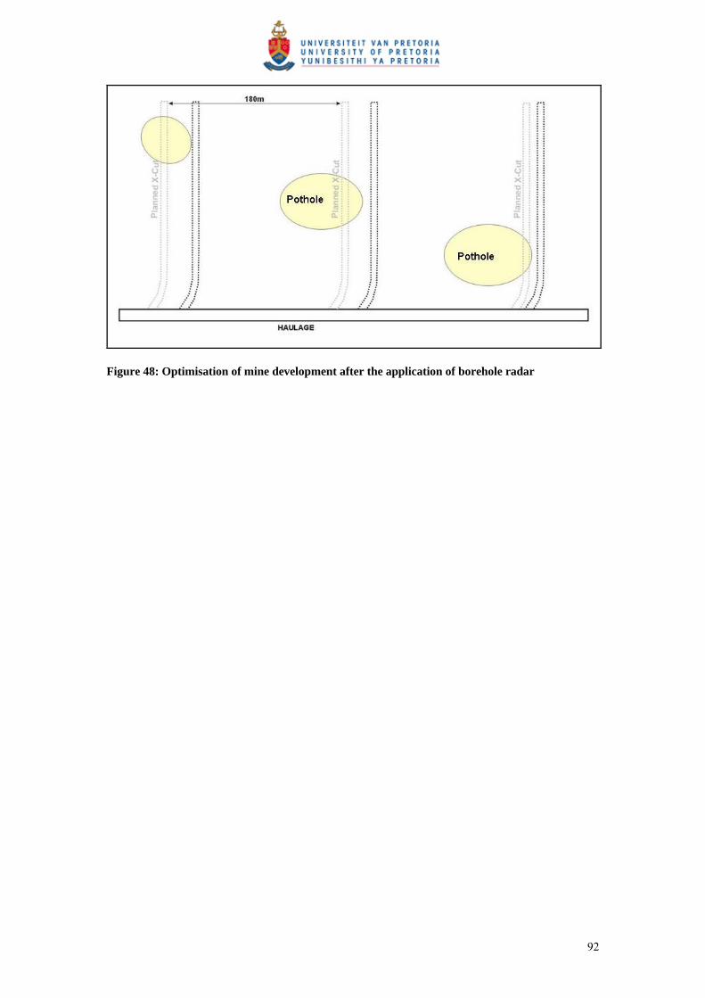
Figure 48: Optimisation of mine development after the application of borehole radar
92

8 ACKNOWLEDGEMENTS
The Platmine Research Collaborative is thanked for allowing this work to be
published.
Declan Vogt at the CSIR, is thanked for many useful discussions and being my
borehole radar guru.
Bruce Walters, Quartus Snyman and Wian Marais at Anglo Platinum are thanked for
their efforts in securing the case-study site at Amandelbult Section as well as for their
inputs in useful discussion relating to the results produced here.
Alan King from Anglo Technical Division is thanked for his valuable input to
financial discussions and for motivating me to go the extra mile.
Andy Rompel Stompel is thanked for checking that a geophysicist is getting the
geology right.
Carel de Jager from Anglo Platinum is thanked for providing the basis of the financial
analysis.
Ferdi Camisani-Calzolari is thanked for teaching me the basics of geostatistics.
Prof. Hennie Theart is thanked for his inputs and suggestions, and for throwing my
first draft across the room.
My family is thanked for giving me nonsense whenever I procrastinated.
My friend, “Eagle-eye” Riaan Wolmarans, is thanked for wading through a very
technical piece of editing.
My friends are thanked for partying on my behalf while I was chained to my
computer.
93

Last but by no means least, my husband, Albert Swart, is thanked for supporting me
in every crazy project that I tackle.
94
9 REFERENCES
Anglo Platinum. (2006) Annual Report.
Carr, H.W., Groves, D.I. and Cawthorn, R.G. (1994). The importance of synmagmatic
deformation of Merensky Reef potholes in the Bushveld Complex, Economic
Geology, 89, 1398 – 1410.
Cawthorn, R.G. (1999). The platinum and palladium resources of the Bushveld
Complex, South African Journal of Science, 95, 481 – 489.
Chalke, B.L., Chalke, T. and Rompel, A.K.K. (2006) Paardekraal #2 Mine Expansion
Project, PDL 159 Geotechnical Interpretation Report. Internal Anglo Technical
Division Report Number 15/173/141/2006/158, 51pp.
Clarke, I. and Harper, W.V. (2000) Practical Geostatistics 2000, Ecosse North
America Llc, Columbus, Ohio, USA. 342pp.
Daniels, J.D. (2004) Ground Penetrating Radar, 2nd Edition. The Institution of
Electrical Engineers, London.
De Jager, C. (2006) Principal Mining Economist, Mining Economics, Anglo
Technical Division, Personal Communication.
De Vries, P. and Du Pisani, P. (2005) Borehole radar delineation of the UG2 Reef at
Modikwa Mine. 9th SAGA Biennial Technical Meeting and Exhibition.
September 2005. Cape Town.
Du Pisani, P. and Vogt, D. (2003) Radar frequency electrical properties of rocks
associated with the VCR, UG2 and Merensky ore bodies. 8th SAGA Biennial
Technical Meeting and Exhibition. September 2003. Pilanesberg.
95

Du Pisani, P. and Vogt, D. (2004) Borehole radar delineation of the Ventersdorp
Contact Reef in Three Dimensions. Exploration Geophysics. 35, 319 – 323.
Du Plessis, A. and Kleywegt, R.J. (1987) A dipping sheet model for the mafic lobes
of the Bushveld Complex. South African Journal of Geology. 90, 1 – 6.
Eales, H.V., Botha, W.J., Hattingh, P.J., De Klerk, W.J., Maier, W.D. and Odgers,
A.T.R. (1993) The mafic rocks of the Bushveld Complex: a review of
emplacement and crystallization history, and mineralization, in light of recent
data. Journal of African Earth Science. 16, 121 – 142.
Eales, H.V. and Cawthorn, R.G. (1996) The Bushveld Complex. In: Cawthorn, R.G.
(Ed.), Layered Intrusions. Elsevier, Amsterdam, 181 – 230.
Farquar, J. (1986) The Western Platinum Mine. In: Anhaeusser, C.R. and Maske, S.
(Eds.), Mineral Deposits of Southern Africa. Geological Society of South
Africa. Johannesburg, South Africa, II, 1135 – 1142.
Heinz, W.F. (1994) Diamond Drilling Handbook 3rd Edition. W.F. Heinz, Halfway
House.
Irvine, T.N. (1982) Terminology for layered intrusions. Journal of Petrology. 23, 127
– 162.
Kinloch, E.D. and Peyerl, W. (1990) Platinum-group minerals in various rock types of
the Merensky Reef: genetic implications. Economic Geology. 85, 537 – 555.
Kruger, F.J. (1990) The stratigraphy of the Bushveld Complex: a reappraisal and the
relocation of the Main Zone boundaries. South African Journal of Geology. 94,
376 – 381.
Leeb Du Toit, A. (1986). The Impala Platinum Mines. In: Anhaeusser, C. R. and
Maske, S (Eds.), Mineral Deposits of Southern Africa. Geological Society of
South Africa. Johannesburg, South Africa, II, 1091 – 1106.
96
Marais, W. (2007) Senior Geologist, Central Functions, Anglo Platinum Rustenburg
Section. Personal communication.
Noon, D.A., Stickley, G.F., and Longstaff, D. (1998). A frequency independent
characterisation of GPR penetration and resolution performance. Journal of
Applied Geophysics. 40, 127 – 137.
Platinum 2007 (2007). Johnson Matthey, Hertfordshyre, England. 56pp.
SAMREC Code. (2000) South African code for reporting of mineral resources and
mineral reserves (the SAMREC code) – Prepared by the South African mineral
resource committee (SAMREC) under the auspices of the SAIMM. Effective
March 2000, SAIMM, Johannesburg, South Africa, 39pp.
Schürmann, L.W. (1991) The geochemistry and petrology of the upper critical zone of
the Boshoek section of the western Bushveld Complex. Bulletin of the
Geological Survey of South Africa. 113, 88pp.
Simmat, C. M., Osman, N., Hargreaves., Mason, I. M., (2002) Borehole radar imaging
from deviating boreholes: Ninth International Conference on Ground
Penetrating Radar, S.K. Koppenjan, H. Lee, (Eds.), Proceedings of SPIE. 4758,
404 – 409.
Turner, G., Mason, I., Hargreaves J., and Wellington, A. (2000) Borehole radar
surveying for orebody delineation: Eighth International Conference on Ground
Penetrating Radar, D.A. Noon., G.F. Stickley, D. Longstaff, (Eds.),
Proceedings of SPIE. 4084, 282 – 287.
Turner, G. and Siggins, A.F. (1994) Constant Q attenuation of subsurface radar
pulses. Geophysics. 59. 1192 – 1200.
Unknown. (1986) A Guide to the Geology of Amandelbult, based on Anhaeusser and
Maske, 1986.
97
Van Wyk, A. (2006) Production Manager, Amandelbult 1-Shaft. Personal
communication.
Viljoen, M.J. (1994) A review of regional variations in facies and grade distribution
of the Merensky Reef, Western Bushveld Complex, with some mining
implications. Proceedings of the 15th CMMI Congress. South African Institute
of Mining and Metallurgy, 183 – 194.
Viljoen, M.J. (1999) The nature and origin of the Merensky Reef of the Western
Bushveld Complex based on geological facies and geophysical data. South
African Journal of Geology. 102. 221 – 239.
Viljoen, M.J. and Hieber, R.W. (1986) The Rustenburg Section of Rustenburg
Platinum Mines Limited, with reference to the Merensky Reef. In: Anhaeusser,
C.R. and Maske, S. (Eds), Mineral Deposits of Southern Africa. Geological
Society of South Africa Johannesburg, South Africa, II. 1107 – 1134.
Viljoen, M.J. and Schürmann, L.W. (1998) Platinum Group Metals. In: Wilson,
M.G.C. and Annhaeusser, C.R. (Eds.), The Mineral Resources of South Africa.
Council for Geoscience, South Africa, Pretoria, 532 – 568.
Viljoen, M.J., De Klerk, W.J., Coetzer., Hatch, N.P., Kinloch, E.D. and Peyerl, W.
(1986a) The Union Section of Rustenburg Platinum Mines Limited, with
reference to the Merensky Reef. In: Anhaeusser, C.R. and Maske, S. (Eds.),
Mineral Deposits of Southern Africa. Geological Society of South Africa,
Johannesburg, South Africa, II. 1061 – 1190.
Viljoen, M.J., Theron, J., Underwood, B., Walters, B.M., Weaver, J. and Peyerl, W.
(1986b) The Amandelbult Section of Rustenburg Platinum Mines Limited, with
reference to the Merensky Reef. In. Anhaeusser, C.R. and Maske, S. (Eds),
Mineral Deposits of Southern Africa. Geological Society of South Africa
Johannesburg, South Africa, II. 1041 – 1060.
98

Vogt, D. (2000) The modelling and design of Radio Tomography antennas: D.Phil.
Thesis, University of York.
Vogt, D. (2002) A Slimline Borehole Radar for In-Mine Use. 9th International
Conference on Ground Penetrating Radar, Proceedings of SPIE, 5758, 31 – 36.
Vogt, D. (2003) An introduction to Ground Penetrating Radar. Course notes for
geophysicists. Wits University. CSIR Miningtek. Johannesburg.
Vogt, D., Van Schoor, M. and Du Pisani, P. (2005) The application of radar
techniques for in-mine feature mapping in the Bushveld Complex of South
Africa. The Journal of the South African Institute of Mining and Metallurgy.
105. 391 – 399.
Vogt, D. (2006) A borehole radar system for South African gold and platinum mines.
South African Journal of Geology. 109. 521 – 528.
Vogt, D. (2007) Competency Area Manager, Mining, Department of Natural
Resources and the Environment, CSIR, Personal communication.
Wagner, P.A. (1929) The Platinum Deposits and Mines of South Africa. Oliver and
Boyd, Edinburgh, Scotland, 326pp.
www.gocurrency.com, [Web page]: accessed 17 September 2007.
www.platmine.co.za, [Web page]: accessed 9 July 2006.
www.platinummetalsreview.com, [Web page]: accessed 12 July 2007.
99

APPENDIX A BOREHOLE INFORMATION
Rock and stratigraphy codes Code ExplanationBR Bastard ReefCOL CollarDYK DykeEOH End of holeFERPL Iron replacementFRAC FractureFRZONE Fracture zoneFWM Footwall markerLN Leuco-noriteMESN Meso-noriteMN Mela-noritePOIKFPYX Poikilitic Feldspathic PyroxenitePOIKPYX Poikilitic PyroxeniteSHR Shear
100

Borehole information for borehole 1 BHID FROM TO X Y Z ROCK10/9W/BHR1 D0 0 0 31791.8 -44745.2 432.665 COL10/9W/BHR1 D0 0 1.43 31792.02 -44744.4 432.543 POIKFPYX10/9W/BHR1 D0 1.43 1.44 31792.3 -44743.8 432.4282 SF10/9W/BHR1 D0 1.44 1.68 31792.35 -44743.6 432.4091 POIKFPYX10/9W/BHR1 D0 1.68 2.06 31792.5 -44743.4 432.3627 MN10/9W/BHR1 D0 2.06 2.07 31792.59 -44743.3 432.3341 SF10/9W/BHR1 D0 2.07 3.91 31793.12 -44742.7 432.2047 MN10/9W/BHR1 D0 3.91 98.7 31839.2 -44754.7 428.3869 MESN10/9W/BHR1 D0 98.7 98.91 31884.71 -44768.2 426.4627 LN10/9W/BHR1 D0 98.91 102.79 31886.67 -44768.7 426.4267 POIKAN10/9W/BHR1 D0 102.79 103.3 31888.78 -44769.4 426.3924 LN10/9W/BHR1 D0 103.3 104.92 31889.8 -44769.7 426.3781 POIKAN10/9W/BHR1 D0 104.92 105.6 31890.9 -44770 426.3646 LN10/9W/BHR1 D0 105.6 114.8 31895.64 -44771.4 426.3275 POIKAN10/9W/BHR1 D0 114.8 115.2 31900.23 -44772.8 426.3198 LN10/9W/BHR1 D0 115.2 117.2 31901.38 -44773.1 426.3226 POIKAN10/9W/BHR1 D0 117.2 118.08 31902.76 -44773.6 426.3287 LN10/9W/BHR1 D0 118.08 123.08 31905.57 -44774.4 426.3506 MESN10/9W/BHR1 D0 123.08 126.04 31909.38 -44775.6 426.4032 POIKAN10/9W/BHR1 D0 126.04 126.1 31910.82 -44776 426.4304 SHR10/9W/BHR1 D0 126.1 126.83 31911.2 -44776.1 426.4381 POIKAN10/9W/BHR1 D0 126.83 135.89 31915.88 -44777.6 426.5486 POIKFPYX10/9W/BHR1 D0 135.89 135.9 31920.21 -44778.9 426.6759 SF10/9W/BHR1 D0 135.9 135.93 31920.23 -44778.9 426.6766 POIKFPYX10/9W/BHR1 D0 135.93 135.95 31920.26 -44778.9 426.6773 SF10/9W/BHR1 D0 135.95 136.01 31920.29 -44778.9 426.6786 DYK10/9W/BHR1 D0 136.01 136.12 31920.38 -44778.9 426.6812 POIKFPYX10/9W/BHR1 D0 136.12 136.55 31920.63 -44779 426.6896 DYK10/9W/BHR1 D0 136.55 137.49 31921.29 -44779.2 426.7112 POIKFPYX10/9W/BHR1 D0 137.49 137.54 31921.76 -44779.4 426.7272 DYK10/9W/BHR1 D0 137.54 138.1 31922.05 -44779.5 426.7372 POIKFPYX10/9W/BHR1 D0 138.1 138.4 31922.46 -44779.6 426.7515 SF10/9W/BHR1 D0 138.4 138.84 31922.82 -44779.7 426.7641 POIKFPYX10/9W/BHR1 D0 138.84 138.85 31923.03 -44779.8 426.7718 SF10/9W/BHR1 D0 138.85 141.16 31924.14 -44780.1 426.8131 POIKFPYX10/9W/BHR1 D0 141.16 141.17 31925.25 -44780.4 426.8568 SF10/9W/BHR1 D0 141.17 143.01 31926.13 -44780.7 426.8933 POIKFPYX10/9W/BHR1 D0 143.01 145.06 31927.99 -44781.3 426.975 POIKAN10/9W/BHR1 D0 145.06 145.09 31928.99 -44781.6 427.0214 DYK10/9W/BHR1 D0 145.09 145.51 31929.2 -44781.6 427.0316 POIKAN10/9W/BHR1 D0 145.51 149.09 31931.12 -44782.2 427.1269 MN
101
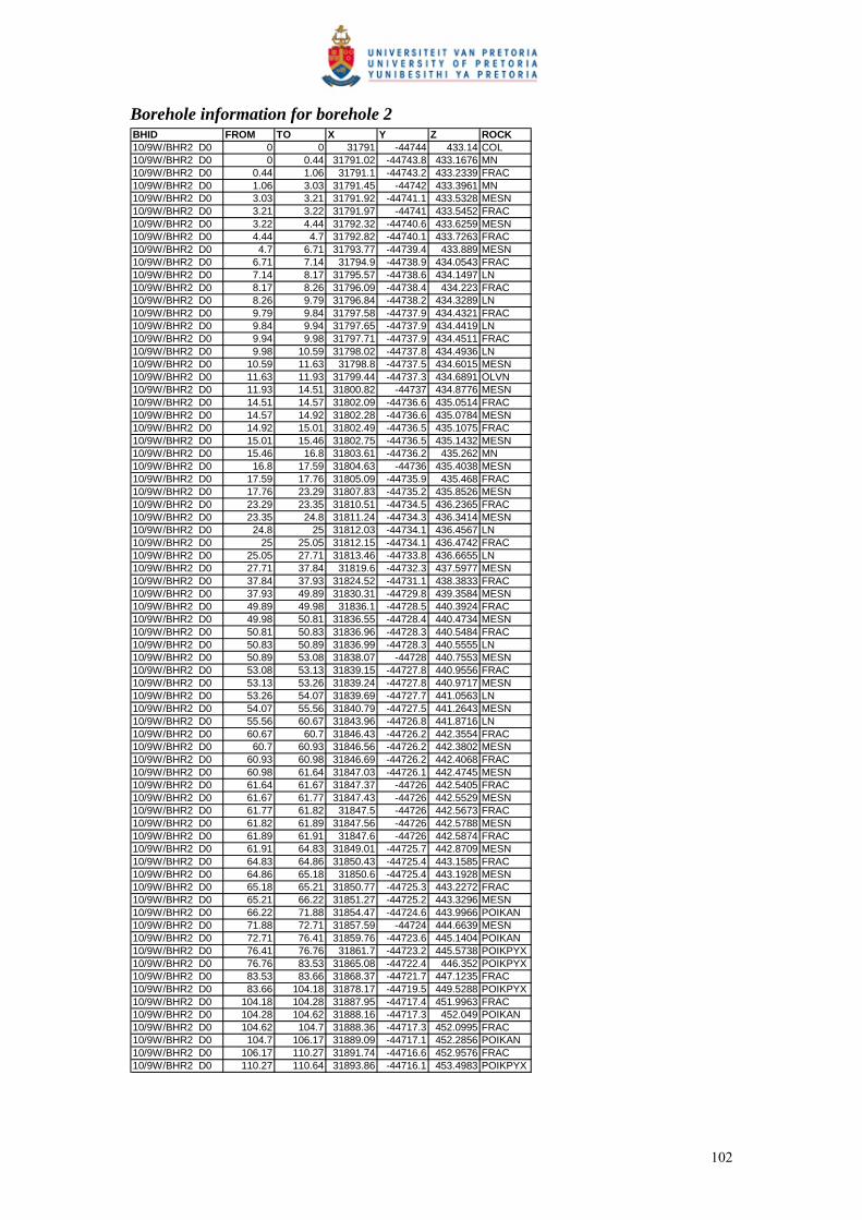
Borehole information for borehole 2 BHID FROM TO X Y Z ROCK10/9W/BHR2 D0 0 0 31791 -44744 433.14 COL10/9W/BHR2 D0 0 0.44 31791.02 -44743.8 433.1676 MN10/9W/BHR2 D0 0.44 1.06 31791.1 -44743.2 433.2339 FRAC10/9W/BHR2 D0 1.06 3.03 31791.45 -44742 433.3961 MN10/9W/BHR2 D0 3.03 3.21 31791.92 -44741.1 433.5328 MESN10/9W/BHR2 D0 3.21 3.22 31791.97 -44741 433.5452 FRAC10/9W/BHR2 D0 3.22 4.44 31792.32 -44740.6 433.6259 MESN10/9W/BHR2 D0 4.44 4.7 31792.82 -44740.1 433.7263 FRAC10/9W/BHR2 D0 4.7 6.71 31793.77 -44739.4 433.889 MESN10/9W/BHR2 D0 6.71 7.14 31794.9 -44738.9 434.0543 FRAC10/9W/BHR2 D0 7.14 8.17 31795.57 -44738.6 434.1497 LN10/9W/BHR2 D0 8.17 8.26 31796.09 -44738.4 434.223 FRAC10/9W/BHR2 D0 8.26 9.79 31796.84 -44738.2 434.3289 LN10/9W/BHR2 D0 9.79 9.84 31797.58 -44737.9 434.4321 FRAC10/9W/BHR2 D0 9.84 9.94 31797.65 -44737.9 434.4419 LN10/9W/BHR2 D0 9.94 9.98 31797.71 -44737.9 434.4511 FRAC10/9W/BHR2 D0 9.98 10.59 31798.02 -44737.8 434.4936 LN10/9W/BHR2 D0 10.59 11.63 31798.8 -44737.5 434.6015 MESN10/9W/BHR2 D0 11.63 11.93 31799.44 -44737.3 434.6891 OLVN10/9W/BHR2 D0 11.93 14.51 31800.82 -44737 434.8776 MESN10/9W/BHR2 D0 14.51 14.57 31802.09 -44736.6 435.0514 FRAC10/9W/BHR2 D0 14.57 14.92 31802.28 -44736.6 435.0784 MESN10/9W/BHR2 D0 14.92 15.01 31802.49 -44736.5 435.1075 FRAC10/9W/BHR2 D0 15.01 15.46 31802.75 -44736.5 435.1432 MESN10/9W/BHR2 D0 15.46 16.8 31803.61 -44736.2 435.262 MN10/9W/BHR2 D0 16.8 17.59 31804.63 -44736 435.4038 MESN10/9W/BHR2 D0 17.59 17.76 31805.09 -44735.9 435.468 FRAC10/9W/BHR2 D0 17.76 23.29 31807.83 -44735.2 435.8526 MESN10/9W/BHR2 D0 23.29 23.35 31810.51 -44734.5 436.2365 FRAC10/9W/BHR2 D0 23.35 24.8 31811.24 -44734.3 436.3414 MESN10/9W/BHR2 D0 24.8 25 31812.03 -44734.1 436.4567 LN10/9W/BHR2 D0 25 25.05 31812.15 -44734.1 436.4742 FRAC10/9W/BHR2 D0 25.05 27.71 31813.46 -44733.8 436.6655 LN10/9W/BHR2 D0 27.71 37.84 31819.6 -44732.3 437.5977 MESN10/9W/BHR2 D0 37.84 37.93 31824.52 -44731.1 438.3833 FRAC10/9W/BHR2 D0 37.93 49.89 31830.31 -44729.8 439.3584 MESN10/9W/BHR2 D0 49.89 49.98 31836.1 -44728.5 440.3924 FRAC10/9W/BHR2 D0 49.98 50.81 31836.55 -44728.4 440.4734 MESN10/9W/BHR2 D0 50.81 50.83 31836.96 -44728.3 440.5484 FRAC10/9W/BHR2 D0 50.83 50.89 31836.99 -44728.3 440.5555 LN10/9W/BHR2 D0 50.89 53.08 31838.07 -44728 440.7553 MESN10/9W/BHR2 D0 53.08 53.13 31839.15 -44727.8 440.9556 FRAC10/9W/BHR2 D0 53.13 53.26 31839.24 -44727.8 440.9717 MESN10/9W/BHR2 D0 53.26 54.07 31839.69 -44727.7 441.0563 LN10/9W/BHR2 D0 54.07 55.56 31840.79 -44727.5 441.2643 MESN10/9W/BHR2 D0 55.56 60.67 31843.96 -44726.8 441.8716 LN10/9W/BHR2 D0 60.67 60.7 31846.43 -44726.2 442.3554 FRAC10/9W/BHR2 D0 60.7 60.93 31846.56 -44726.2 442.3802 MESN10/9W/BHR2 D0 60.93 60.98 31846.69 -44726.2 442.4068 FRAC10/9W/BHR2 D0 60.98 61.64 31847.03 -44726.1 442.4745 MESN10/9W/BHR2 D0 61.64 61.67 31847.37 -44726 442.5405 FRAC10/9W/BHR2 D0 61.67 61.77 31847.43 -44726 442.5529 MESN10/9W/BHR2 D0 61.77 61.82 31847.5 -44726 442.5673 FRAC10/9W/BHR2 D0 61.82 61.89 31847.56 -44726 442.5788 MESN10/9W/BHR2 D0 61.89 61.91 31847.6 -44726 442.5874 FRAC10/9W/BHR2 D0 61.91 64.83 31849.01 -44725.7 442.8709 MESN10/9W/BHR2 D0 64.83 64.86 31850.43 -44725.4 443.1585 FRAC10/9W/BHR2 D0 64.86 65.18 31850.6 -44725.4 443.1928 MESN10/9W/BHR2 D0 65.18 65.21 31850.77 -44725.3 443.2272 FRAC10/9W/BHR2 D0 65.21 66.22 31851.27 -44725.2 443.3296 MESN10/9W/BHR2 D0 66.22 71.88 31854.47 -44724.6 443.9966 POIKAN10/9W/BHR2 D0 71.88 72.71 31857.59 -44724 444.6639 MESN10/9W/BHR2 D0 72.71 76.41 31859.76 -44723.6 445.1404 POIKAN10/9W/BHR2 D0 76.41 76.76 31861.7 -44723.2 445.5738 POIKPYX10/9W/BHR2 D0 76.76 83.53 31865.08 -44722.4 446.352 POIKPYX10/9W/BHR2 D0 83.53 83.66 31868.37 -44721.7 447.1235 FRAC10/9W/BHR2 D0 83.66 104.18 31878.17 -44719.5 449.5288 POIKPYX10/9W/BHR2 D0 104.18 104.28 31887.95 -44717.4 451.9963 FRAC10/9W/BHR2 D0 104.28 104.62 31888.16 -44717.3 452.049 POIKAN10/9W/BHR2 D0 104.62 104.7 31888.36 -44717.3 452.0995 FRAC10/9W/BHR2 D0 104.7 106.17 31889.09 -44717.1 452.2856 POIKAN10/9W/BHR2 D0 106.17 110.27 31891.74 -44716.6 452.9576 FRAC10/9W/BHR2 D0 110.27 110.64 31893.86 -44716.1 453.4983 POIKPYX
102

Borehole information for borehole 3 BHID FROM TO X Y Z ROCK10/9W/BHR3 D0 0 0 31794.4 -44748 432.013 COL10/9W/BHR3 D0 0 1.5 31794.69 -44747.2 431.7234 MN10/9W/BHR3 D0 1.5 7.95 31797.11 -44745.7 430.3627 MESN10/9W/BHR3 D0 7.95 16.69 31803.24 -44749.9 428.6192 LN10/9W/BHR3 D0 16.69 41.75 31816.25 -44760.2 425.3955 MESN10/9W/BHR3 D0 41.75 49.1 31828.74 -44770.1 422.5459 LN10/9W/BHR3 D0 49.1 58.43 31835.19 -44775.2 421.1751 MESN10/9W/BHR3 D0 58.43 70.48 31843.49 -44781.8 419.5261 LN10/9W/BHR3 D0 70.48 73.56 31849.36 -44786.4 418.4584 MESN10/9W/BHR3 D0 73.56 76.33 31851.63 -44788.2 418.0689 LN10/9W/BHR3 D0 76.33 78.53 31853.56 -44789.8 417.7497 MESN10/9W/BHR3 D0 78.53 86.51 31857.52 -44792.9 417.1351 LN10/9W/BHR3 D0 86.51 97.48 31864.89 -44798.8 416.1231 LN10/9W/BHR3 D0 97.48 101.65 31870.77 -44803.5 415.4192 POIKAN10/9W/BHR3 D0 101.65 102.14 31872.58 -44804.9 415.2199 MESN10/9W/BHR3 D0 102.14 102.41 31872.88 -44805.2 415.1882 LN10/9W/BHR3 D0 102.41 111.18 31876.39 -44808 414.8332 POIKAN10/9W/BHR3 D0 111.18 111.57 31879.96 -44810.8 414.5125 MESN10/9W/BHR3 D0 111.57 114.55 31881.27 -44811.9 414.4024 POIKAN10/9W/BHR3 D0 114.55 116.08 31883.02 -44813.3 414.2617 LN10/9W/BHR3 D0 116.08 116.51 31883.78 -44813.9 414.2032 POIKAN10/9W/BHR3 D0 116.51 116.67 31884.01 -44814.1 414.1859 MESN10/9W/BHR3 D0 116.67 119.15 31885.04 -44814.9 414.1105 LN10/9W/BHR3 D0 119.15 119.39 31886.09 -44815.8 414.036 FRAC10/9W/BHR3 D0 119.39 119.65 31886.29 -44815.9 414.0226 LN10/9W/BHR3 D0 119.65 119.85 31886.46 -44816.1 414.0105 DYK10/9W/BHR3 D0 119.85 121.36 31887.13 -44816.6 413.9659 LN10/9W/BHR3 D0 121.36 125.48 31889.31 -44818.4 413.8268 POIKAN10/9W/BHR3 D0 125.48 125.6 31890.95 -44819.7 413.7297 FRAC10/9W/BHR3 D0 125.6 127.03 31891.55 -44820.2 413.6957 POIKPYX10/9W/BHR3 D0 127.03 127.1 31892.13 -44820.7 413.6627 DYK10/9W/BHR3 D0 127.1 127.25 31892.21 -44820.8 413.6578 POIKPYX10/9W/BHR3 D0 127.25 127.37 31892.31 -44820.9 413.6518 DYK10/9W/BHR3 D0 127.37 162.8 31906.04 -44832.1 412.859 POIKPYX10/9W/BHR3 D0 162.8 163.44 31920.01 -44843.5 411.9177 POIKPYX10/9W/BHR3 D0 163.44 174.71 31924.35 -44847.6 411.5753 POIKPYX10/9W/BHR3 D0 174.71 175.93 31928.95 -44851.8 411.2388 MN10/9W/BHR3 D0 175.93 176.39 31929.58 -44852.3 411.1966 MESN10/9W/BHR3 D0 176.39 176.46 31929.78 -44852.5 411.1834 LN10/9W/BHR3 D0 176.46 213.26 31943.73 -44864.5 410.5221 POIKAN
103

Borehole information for borehole 4 BHID FROM TO X Y Z ROCK10/9W/BHR4 D0 0 0 31790.2 -44743 433.554 COL10/9W/BHR4 D0 0 4.4 31790.45 -44740.9 434.1758 POIKPYX10/9W/BHR4 D0 4.4 25.56 31797.6 -44731 437.4726 MESN10/9W/BHR4 D0 25.56 39.28 31808.91 -44718.6 442.0609 MN10/9W/BHR4 D0 39.28 83.52 31827.71 -44698.1 450.3586 MESN10/9W/BHR4 D0 83.52 85.33 31842.6 -44682.2 457.7849 LN10/9W/BHR4 D0 85.33 96.46 31846.75 -44677.8 460.0024 MESN10/9W/BHR4 D0 96.46 97.17 31850.56 -44673.7 462.0715 POIKPYX10/9W/BHR4 D0 97.17 97.4 31850.86 -44673.4 462.2373 MESN10/9W/BHR4 D0 97.17 97.4 31850.86 -44673.4 462.2373 MESN10/9W/BHR4 D0 97.4 97.87 31851.09 -44673.2 462.3609 FERPL10/9W/BHR4 D0 97.87 103.34 31853.06 -44671.2 463.4136 POIKPYX10/9W/BHR4 D0 103.34 106.56 31856 -44668.4 464.9654 FERPL10/9W/BHR4 D0 106.56 108.14 31857.6 -44666.9 465.8271 POIKPYX10/9W/BHR4 D0 108.14 108.34 31858.19 -44666.3 466.1474 FRAC10/9W/BHR4 D0 108.34 109.7 31858.7 -44665.8 466.4285 POIKPYX10/9W/BHR4 D0 109.7 109.83 31859.19 -44665.3 466.6972 FRAC10/9W/BHR4 D0 109.83 109.87 31859.25 -44665.2 466.7279 POIKPYX10/9W/BHR4 D0 109.87 110.01 31859.31 -44665.2 466.7604 FRAC10/9W/BHR4 D0 110.01 129.71 31865.74 -44658.5 470.3781 POIKPYX10/9W/BHR4 D0 129.71 129.82 31872.19 -44652 474.0662 DYK10/9W/BHR4 D0 129.82 139.75 31875.43 -44648.6 475.9535 POIKPYX
104

APPENDIX B BOREHOLE RADAR ILLUMINATION LINE
COORDINATES
Borehole 1: Borehole radar illumination line coordinates – dip direction
X Y Z X Y Z31791 -44739.5 426.972 31843.2 -44756.3 413.384
31839.1 -44754 413.39 31842.1 -44755.7 413.35431839 -44753.6 413.412 31841.1 -44755 413.348
31838.2 -44753 413.471 31840.1 -44754.3 413.36531837.2 -44752.3 413.559 31839.1 -44753.6 413.40631836.3 -44751.7 413.671 31894.5 -44766.3 410.89431835.5 -44751 413.807 31892.9 -44766.1 411.0831834.6 -44750.4 413.966 31889.8 -44765.4 411.48931833.8 -44749.7 414.149 31886.7 -44764.9 411.854
31833 -44749.1 414.356 31908 -44769 408.92231832.2 -44748.5 414.586 31907.2 -44768.9 409.00531831.4 -44747.9 414.84 31903.4 -44768.2 409.5931830.6 -44747.3 415.118 31899.7 -44767.4 410.13131830.1 -44746.6 415.42 31896.3 -44766.7 410.62831829.7 -44745.9 415.763 31918.6 -44771.2 407.19431828.9 -44745.3 416.168 31915.4 -44770.6 407.70231827.8 -44744.7 416.633 31911.2 -44769.8 408.37631826.5 -44744.1 417.16 31919.8 -44771.5 406.98531824.9 -44743.5 417.747
31823 -44742.9 418.39531820.9 -44742.4 419.10531818.5 -44741.9 419.87531815.8 -44741.4 420.70631812.9 -44740.9 421.59831809.8 -44740.4 422.55131806.4 -44740 423.56531802.7 -44739.5 424.63931798.9 -44739.1 425.77531885.8 -44764.6 411.97631883.8 -44764.4 412.174
31881 -44763.9 412.4531878.3 -44763.5 412.68231875.6 -44763.2 412.87131872.9 -44762.9 413.01431870.7 -44762.7 413.11431868.9 -44762.3 413.18831867.2 -44762 413.25431865.4 -44761.6 413.31231863.6 -44761.2 413.36231861.8 -44760.8 413.404
31860 -44760.4 413.43731858.2 -44760 413.46331856.3 -44759.6 413.48131854.4 -44759.2 413.49131852.5 -44758.7 413.49331850.6 -44758.3 413.48831848.7 -44757.8 413.47431846.7 -44757.4 413.45231844.7 -44756.9 413.422
105
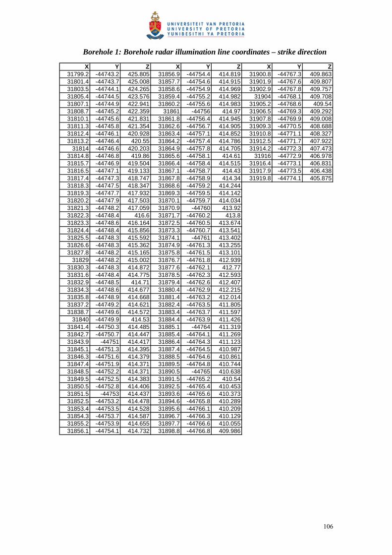
Borehole 1: Borehole radar illumination line coordinates – strike direction
X Y Z X Y Z X Y Z31799.2 -44743.2 425.805 31856.9 -44754.4 414.819 31900.8 -44767.3 409.86331801.4 -44743.7 425.008 31857.7 -44754.6 414.915 31901.9 -44767.6 409.80731803.5 -44744.1 424.265 31858.6 -44754.9 414.969 31902.9 -44767.8 409.75731805.4 -44744.5 423.576 31859.4 -44755.2 414.982 31904 -44768.1 409.70831807.1 -44744.9 422.941 31860.2 -44755.6 414.983 31905.2 -44768.6 409.5431808.7 -44745.2 422.359 31861 -44756 414.97 31906.5 -44769.3 409.29231810.1 -44745.6 421.831 31861.8 -44756.4 414.945 31907.8 -44769.9 409.00831811.3 -44745.8 421.354 31862.6 -44756.7 414.905 31909.3 -44770.5 408.68831812.4 -44746.1 420.928 31863.4 -44757.1 414.852 31910.8 -44771.1 408.32731813.2 -44746.4 420.55 31864.2 -44757.4 414.786 31912.5 -44771.7 407.922
31814 -44746.6 420.203 31864.9 -44757.8 414.705 31914.2 -44772.3 407.47331814.8 -44746.8 419.86 31865.6 -44758.1 414.61 31916 -44772.9 406.97831815.7 -44746.9 419.504 31866.4 -44758.4 414.515 31916.4 -44773.1 406.83131816.5 -44747.1 419.133 31867.1 -44758.7 414.43 31917.9 -44773.5 406.43831817.4 -44747.3 418.747 31867.8 -44758.9 414.34 31919.8 -44774.1 405.87531818.3 -44747.5 418.347 31868.6 -44759.2 414.24431819.3 -44747.7 417.932 31869.3 -44759.5 414.14231820.2 -44747.9 417.503 31870.1 -44759.7 414.03431821.3 -44748.2 417.059 31870.9 -44760 413.9231822.3 -44748.4 416.6 31871.7 -44760.2 413.831823.3 -44748.6 416.164 31872.5 -44760.5 413.67431824.4 -44748.4 415.856 31873.3 -44760.7 413.54131825.5 -44748.3 415.592 31874.1 -44761 413.40231826.6 -44748.3 415.362 31874.9 -44761.3 413.25531827.8 -44748.2 415.165 31875.8 -44761.5 413.101
31829 -44748.2 415.002 31876.7 -44761.8 412.93931830.3 -44748.3 414.872 31877.6 -44762.1 412.7731831.6 -44748.4 414.775 31878.5 -44762.3 412.59331832.9 -44748.5 414.71 31879.4 -44762.6 412.40731834.3 -44748.6 414.677 31880.4 -44762.9 412.21531835.8 -44748.9 414.668 31881.4 -44763.2 412.01431837.2 -44749.2 414.621 31882.4 -44763.5 411.80531838.7 -44749.6 414.572 31883.4 -44763.7 411.597
31840 -44749.9 414.53 31884.4 -44763.9 411.42631841.4 -44750.3 414.485 31885.1 -44764 411.31931842.7 -44750.7 414.447 31885.4 -44764.1 411.26931843.9 -44751 414.417 31886.4 -44764.3 411.12331845.1 -44751.3 414.395 31887.4 -44764.5 410.98731846.3 -44751.6 414.379 31888.5 -44764.6 410.86131847.4 -44751.9 414.371 31889.5 -44764.8 410.74431848.5 -44752.2 414.371 31890.5 -44765 410.63831849.5 -44752.5 414.383 31891.5 -44765.2 410.5431850.5 -44752.8 414.406 31892.5 -44765.4 410.45331851.5 -44753 414.437 31893.6 -44765.6 410.37331852.5 -44753.2 414.478 31894.6 -44765.8 410.28931853.4 -44753.5 414.528 31895.6 -44766.1 410.20931854.3 -44753.7 414.587 31896.7 -44766.3 410.12931855.2 -44753.9 414.655 31897.7 -44766.6 410.05531856.1 -44754.1 414.732 31898.8 -44766.8 409.986
106

Borehole 2: Borehole radar illumination line coordinates – strike direction
X Y Z X Y Z X Y Z31793.1 -44738.4 429.094 31825.6 -44727.2 427.845 31865.9 -44715.5 426.81131794.2 -44737.4 429.105 31826.4 -44727 427.838 31866.8 -44715.2 426.82331794.4 -44737.2 429.106 31827.3 -44726.7 427.822 31867.3 -44715.1 426.82231795.3 -44736.8 429.01 31828.2 -44726.4 427.796 31867.2 -44715.1 426.82931796.4 -44736.3 428.896 31828.8 -44726.3 427.774 31868.5 -44714.8 426.87131796.7 -44736.2 428.857 31829.1 -44726.2 427.76 31870 -44714.4 426.94931797.4 -44735.9 428.777 31830 -44725.9 427.715 31871.6 -44714 427.0631798.4 -44735.6 428.659 31831 -44725.6 427.659 31873.3 -44713.5 427.20731799.4 -44735.2 428.553 31832 -44725.2 427.593 31875.2 -44713.1 427.38731800.3 -44734.9 428.457 31833 -44724.9 427.524 31877.2 -44712.6 427.60231801.1 -44734.6 428.373 31834 -44724.6 427.457 31878.9 -44712.1 427.80431801.4 -44734.5 428.342 31834.5 -44724.5 427.425 31879.3 -44712 427.85131801.9 -44734.3 428.296 31835 -44724.3 427.393 31881.5 -44711.5 428.13331802.6 -44734.1 428.23 31836 -44724 427.333 31883.8 -44710.9 428.44931803.3 -44733.8 428.174 31837 -44723.7 427.277 31886.3 -44710.3 428.798
31804 -44733.6 428.129 31837.9 -44723.5 427.225 31888.9 -44709.6 429.18131804.6 -44733.4 428.089 31838.8 -44723.2 427.178 31889.5 -44709.5 429.27831805.3 -44733.2 428.05 31839.7 -44722.9 427.133 31891.6 -44709 429.59431805.9 -44733 428.011 31840.6 -44722.7 427.09431806.6 -44732.8 427.972 31841.5 -44722.4 427.05831807.2 -44732.6 427.932 31842.4 -44722.2 427.02631807.9 -44732.4 427.892 31843.2 -44721.9 426.99931808.6 -44732.2 427.852 31844.1 -44721.7 426.97531809.3 -44731.9 427.813 31844.7 -44721.5 426.959
31810 -44731.7 427.774 31844.9 -44721.4 426.95431810.7 -44731.5 427.735 31845.7 -44721.2 426.93331810.8 -44731.4 427.727 31846.5 -44721 426.91331811.4 -44731.3 427.695 31847.3 -44720.8 426.89531812.1 -44731 427.656 31848.1 -44720.5 426.87831812.9 -44730.8 427.617 31848.9 -44720.3 426.86331813.6 -44730.6 427.583 31849.7 -44720.1 426.84731814.3 -44730.4 427.557 31850.5 -44719.9 426.833
31815 -44730.2 427.537 31851.2 -44719.7 426.8231815.7 -44730 427.524 31852 -44719.5 426.80831816.4 -44729.8 427.519 31852.7 -44719.3 426.79831817.1 -44729.6 427.52 31853.5 -44719.1 426.78931817.8 -44729.4 427.529 31854.2 -44718.9 426.78131818.5 -44729.2 427.545 31855 -44718.7 426.77431819.1 -44729 427.564 31855.8 -44718.4 426.76831819.2 -44729 427.568 31856 -44718.4 426.76731819.9 -44728.8 427.597 31856.7 -44718.2 426.76731820.5 -44728.7 427.634 31857.5 -44717.9 426.76731821.2 -44728.5 427.678 31858.5 -44717.7 426.76931821.9 -44728.3 427.726 31859.4 -44717.4 426.77131822.5 -44728.1 427.77 31860.4 -44717.1 426.77431823.3 -44727.9 427.804 31861.4 -44716.8 426.77831823.9 -44727.7 427.824 31862.5 -44716.5 426.783
31824 -44727.7 427.828 31863.4 -44716.3 426.78731824.8 -44727.5 427.841 31863.6 -44716.2 426.789
107
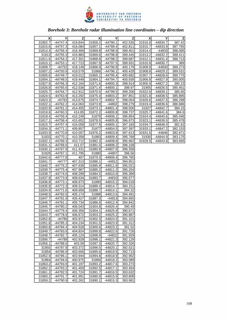
Borehole 3: Borehole radar illumination line coordinates – dip direction
X Y Z X Y Z X Y Z31802.7 -44747.4 419.844 31858.2 -44790.1 402.535 31916.9 -44834.7 387.4231815.6 -44757.3 416.084 31857.1 -44789.4 402.811 31915.7 -44833.9 387.76531814.4 -44756.4 416.469 31869.8 -44798.9 399.401 31914.4 -44833 388.095
31813 -44755.3 416.883 31869.6 -44798.8 399.445 31913.2 -44832.2 388.41131811.6 -44754.2 417.301 31868.8 -44798.2 399.687 31912.1 -44831.4 388.71331810.1 -44753.1 417.723 31867.9 -44797.5 399.931 31910.9 -44830.7 38931808.7 -44752 418.149 31866.9 -44796.8 400.179 31909.8 -44830 389.27331807.2 -44750.9 418.579 31866 -44796.1 400.429 31908.8 -44829.2 389.53131805.6 -44749.7 419.012 31865.1 -44795.4 400.682 31907.7 -44828.6 389.77531804.1 -44748.5 419.449 31864.1 -44794.7 400.939 31906.8 -44827.9 390.00531827.9 -44766.3 412.164 31871.6 -44800.3 398.914 31905.9 -44827.2 390.2331826.8 -44765.6 412.536 31871.4 -44800.1 398.97 31905 -44826.5 390.45131825.7 -44764.7 412.912 31870.5 -44799.5 399.206 31922.6 -44839.1 385.6531824.5 -44763.9 413.292 31875.4 -44803.2 397.851 31921.8 -44838.5 385.89531823.3 -44763 413.676 31874.7 -44802.7 398.054 31920.6 -44837.5 386.29831822.1 -44762.2 414.063 31873.9 -44802 398.279 31919.4 -44836.6 386.68631820.9 -44761.2 414.455 31873.1 -44801.4 398.506 31927 -44842.7 384.1531819.6 -44760.3 414.85 31872.2 -44800.8 398.737 31925.7 -44841.6 384.631818.4 -44759.4 415.249 31879 -44806.1 396.854 31924.4 -44840.6 385.04631817.1 -44758.4 415.652 31878.5 -44805.8 396.973 31923.1 -44839.5 385.47831815.7 -44757.4 416.058 31877.8 -44805.1 397.183 31934.7 -44848.4 381.6231834.3 -44771.1 409.857 31877 -44804.5 397.397 31933.1 -44847.2 382.15331833.9 -44770.8 410.007 31876.2 -44803.9 397.613 31931.5 -44846 382.671
31833 -44770.1 410.358 31883 -44809.4 395.768 31930 -44844.9 383.17531832.1 -44769.3 410.712 31882.3 -44808.8 395.962 31928.5 -44843.8 383.66531831.1 -44768.6 411.07 31881.5 -44808.2 396.15831830.1 -44767.9 411.431 31880.8 -44807.6 396.358
31829 -44767.1 411.795 31880 -44807 396.5631842.6 -44777.8 407 31879.3 -44806.4 396.76531841.7 -44777 407.313 31886.1 -44812 394.95131840.7 -44776.2 407.639 31885.9 -44811.8 395.02131839.7 -44775.4 407.967 31885.2 -44811.2 395.20431838.7 -44774.6 408.299 31884.5 -44810.6 395.38931837.8 -44773.9 408.634 31883.7 -44810 395.57731836.8 -44773.1 408.973 31890 -44815.2 394.01831835.8 -44772.3 409.314 31889.4 -44814.7 394.15131834.9 -44771.6 409.659 31888.7 -44814.1 394.3231848.5 -44782.6 405.174 31888 -44813.6 394.49131847.7 -44781.9 405.427 31887.3 -44813 394.66531846.7 -44781.1 405.734 31886.6 -44812.4 394.84231845.7 -44780.2 406.043 31904.8 -44826.4 390.4931844.7 -44779.4 406.356 31904.1 -44825.9 390.67131843.7 -44778.6 406.672 31903.2 -44825.2 390.88731852.8 -44786 403.971 31902.3 -44824.5 391.10131851.8 -44785.3 404.234 31901.5 -44823.9 391.31231850.8 -44784.4 404.528 31900.6 -44823.2 391.5231849.7 -44783.6 404.824 31899.8 -44822.6 391.72631848.7 -44782.7 405.124 31898.9 -44822 391.92931856.7 -44789 402.929 31898.1 -44821.3 392.12931856.1 -44788.6 403.09 31897.3 -44820.7 392.326
31855 -44787.8 403.372 31896.5 -44820.1 392.52131854 -44786.9 403.656 31895.6 -44819.5 392.713
31852.9 -44786.1 403.944 31894.8 -44818.9 392.90231864 -44794.6 400.975 31894 -44818.2 393.089
31863.2 -44793.9 401.197 31893.2 -44817.6 393.27331862.2 -44793.2 401.459 31892.5 -44817.1 393.45431861.2 -44792.5 401.724 31891.7 -44816.5 393.63231860.2 -44791.7 401.991 31890.9 -44815.9 393.80831859.2 -44790.9 402.262 31890.1 -44815.3 393.981
108
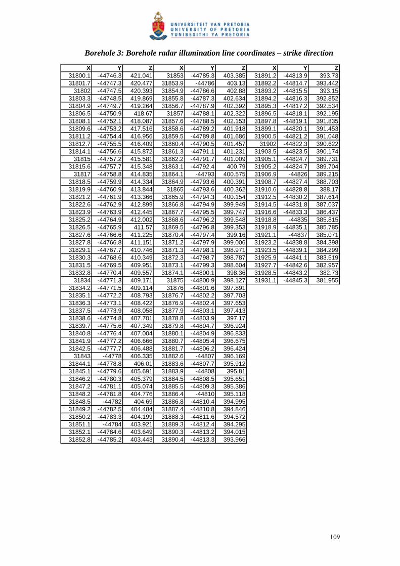
Borehole 3: Borehole radar illumination line coordinates – strike direction
X Y Z X Y Z X Y Z31800.1 -44746.3 421.041 31853 -44785.3 403.385 31891.2 -44813.9 393.7331801.7 -44747.3 420.477 31853.9 -44786 403.13 31892.2 -44814.7 393.442
31802 -44747.5 420.393 31854.9 -44786.6 402.88 31893.2 -44815.5 393.1531803.3 -44748.5 419.869 31855.8 -44787.3 402.634 31894.2 -44816.3 392.85231804.9 -44749.7 419.264 31856.7 -44787.9 402.392 31895.3 -44817.2 392.53431806.5 -44750.9 418.67 31857 -44788.1 402.322 31896.5 -44818.1 392.19531808.1 -44752.1 418.087 31857.6 -44788.5 402.153 31897.8 -44819.1 391.83531809.6 -44753.2 417.516 31858.6 -44789.2 401.918 31899.1 -44820.1 391.45331811.2 -44754.4 416.956 31859.5 -44789.8 401.686 31900.5 -44821.2 391.04831812.7 -44755.5 416.409 31860.4 -44790.5 401.457 31902 -44822.3 390.62231814.1 -44756.6 415.872 31861.3 -44791.1 401.231 31903.5 -44823.5 390.174
31815 -44757.2 415.581 31862.2 -44791.7 401.009 31905.1 -44824.7 389.73131815.6 -44757.7 415.348 31863.1 -44792.4 400.79 31905.2 -44824.7 389.704
31817 -44758.8 414.835 31864.1 -44793 400.575 31906.9 -44826 389.21531818.5 -44759.9 414.334 31864.9 -44793.6 400.391 31908.7 -44827.4 388.70331819.9 -44760.9 413.844 31865 -44793.6 400.362 31910.6 -44828.8 388.1731821.2 -44761.9 413.366 31865.9 -44794.3 400.154 31912.5 -44830.2 387.61431822.6 -44762.9 412.899 31866.8 -44794.9 399.949 31914.5 -44831.8 387.03731823.9 -44763.9 412.445 31867.7 -44795.5 399.747 31916.6 -44833.3 386.43731825.2 -44764.9 412.002 31868.6 -44796.2 399.548 31918.8 -44835 385.81531826.5 -44765.9 411.57 31869.5 -44796.8 399.353 31918.9 -44835.1 385.78531827.6 -44766.6 411.225 31870.4 -44797.4 399.16 31921.1 -44837 385.07131827.8 -44766.8 411.151 31871.2 -44797.9 399.006 31923.2 -44838.8 384.39831829.1 -44767.7 410.746 31871.3 -44798.1 398.971 31923.5 -44839.1 384.29931830.3 -44768.6 410.349 31872.3 -44798.7 398.787 31925.9 -44841.1 383.51931831.5 -44769.5 409.951 31873.1 -44799.3 398.604 31927.7 -44842.6 382.95731832.8 -44770.4 409.557 31874.1 -44800.1 398.36 31928.5 -44843.2 382.73
31834 -44771.3 409.171 31875 -44800.9 398.127 31931.1 -44845.3 381.95531834.2 -44771.5 409.114 31876 -44801.6 397.89131835.1 -44772.2 408.793 31876.7 -44802.2 397.70331836.3 -44773.1 408.422 31876.9 -44802.4 397.65331837.5 -44773.9 408.058 31877.9 -44803.1 397.41331838.6 -44774.8 407.701 31878.8 -44803.9 397.1731839.7 -44775.6 407.349 31879.8 -44804.7 396.92431840.8 -44776.4 407.004 31880.1 -44804.9 396.83331841.9 -44777.2 406.666 31880.7 -44805.4 396.67531842.5 -44777.7 406.488 31881.7 -44806.2 396.424
31843 -44778 406.335 31882.6 -44807 396.16931844.1 -44778.8 406.01 31883.6 -44807.7 395.91231845.1 -44779.6 405.691 31883.9 -44808 395.8131846.2 -44780.3 405.379 31884.5 -44808.5 395.65131847.2 -44781.1 405.074 31885.5 -44809.3 395.38631848.2 -44781.8 404.776 31886.4 -44810 395.11831848.5 -44782 404.69 31886.8 -44810.4 394.99531849.2 -44782.5 404.484 31887.4 -44810.8 394.84631850.2 -44783.3 404.199 31888.3 -44811.6 394.57231851.1 -44784 403.921 31889.3 -44812.4 394.29531852.1 -44784.6 403.649 31890.3 -44813.2 394.01531852.8 -44785.2 403.443 31890.4 -44813.3 393.966
109

Borehole 4: Borehole radar illumination line coordinates – dip direction
X Y Z X Y Z31790.1 -44741.9 430.542 31832.6 -44690.7 440.79731790.3 -44740.5 430.825 31833.2 -44689.4 441.00831790.3 -44740.2 430.898 31833.7 -44688.2 441.257
31791 -44739.1 431.088 31834.1 -44687.1 441.54231792 -44737.8 431.331 31834.4 -44686.1 441.864
31792.9 -44736.5 431.555 31834.5 -44685.1 442.22331793.8 -44735.3 431.76 31834.6 -44684.2 442.61931794.5 -44734.2 431.944 31834.6 -44683.4 443.05131795.3 -44733.1 432.109 31834.6 -44682.6 443.52131795.9 -44732.2 432.278 31834.9 -44681.8 444.06531796.3 -44731.3 432.489 31835.6 -44680.7 444.70431796.7 -44730.4 432.744 31836.6 -44679.5 445.43831797.2 -44729.5 433.042 31837.8 -44678.1 446.26831797.2 -44729.2 433.149 31839.1 -44676.7 447.19431797.8 -44728.5 433.383 31840.6 -44675.1 448.21431798.5 -44727.6 433.768 31841 -44674.6 448.51631799.2 -44726.6 434.196 31842.3 -44673.4 449.33
31800 -44725.6 434.668 31844.1 -44671.5 450.54131800.8 -44724.6 435.183 31845.2 -44670.4 451.27731801.7 -44723.6 435.722 31846.1 -44669.5 451.84831802.8 -44722.5 436.23231803.9 -44721.5 436.712
31805 -44720.5 437.1631806.1 -44719.4 437.57731807.1 -44718.4 437.96231808.2 -44717.4 438.31631808.6 -44717.1 438.41731809.2 -44716.4 438.63831810.2 -44715.4 438.92931811.2 -44714.4 439.18931812.3 -44713.4 439.41631813.4 -44712.3 439.6131814.6 -44711.2 439.77231815.8 -44710.1 439.90131817.1 -44708.9 439.99831818.4 -44707.7 440.06231819.7 -44706.5 440.09431821.2 -44705.3 440.09231822.6 -44704 440.06331823.6 -44702.7 440.04631824.6 -44701.5 440.04831825.5 -44700.2 440.0731826.5 -44699 440.11231827.5 -44697.6 440.17431827.6 -44697.4 440.1931828.6 -44696.3 440.25631829.6 -44694.9 440.35831830.7 -44693.5 440.4831831.8 -44692 440.622
110

Borehole 4: Borehole radar illumination line coordinates – strike direction
X Y Z X Y Z31789.5 -44740.1 431.174 31818.2 -44704.1 440.146
31790 -44739.3 431.236 31819.3 -44702.6 440.231790.9 -44737.9 431.35 31820.4 -44701.1 440.22631791.8 -44736.6 431.472 31821.5 -44699.8 440.23931792.6 -44735.4 431.604 31822.6 -44698.5 440.2731793.5 -44734.3 431.745 31823.7 -44697.3 440.3231794.2 -44733.3 431.894 31824.8 -44696.1 440.389
31795 -44732.4 432.052 31825.6 -44695.3 440.44431795.6 -44731.6 432.219 31825.8 -44695 440.4831796.3 -44731 432.393 31826.9 -44693.9 440.59331796.9 -44730.4 432.575 31827.9 -44692.9 440.72531797.5 -44730 432.763 31829 -44691.9 440.87831798.1 -44729.6 432.958 31830 -44691 441.05331798.5 -44729.4 433.15 31831 -44690.1 441.248
31799 -44728.9 433.454 31832 -44689.3 441.46631799.5 -44728.3 433.744 31833 -44688.5 441.70931799.9 -44727.8 434.025 31834.1 -44687.7 442.00631800.4 -44727.2 434.298 31835.3 -44686.7 442.39731800.8 -44726.7 434.561 31836.6 -44685.6 442.88431801.3 -44726.1 434.817 31838 -44684.4 443.46331801.7 -44725.6 435.063 31839.4 -44683.1 444.13331802.2 -44725.1 435.302 31841 -44681.6 444.89331802.6 -44724.5 435.532 31842.6 -44680 445.74131803.1 -44724 435.753 31844.4 -44678.4 446.67731803.5 -44723.4 435.967 31844.7 -44678.1 446.826
31804 -44722.8 436.173 31846.2 -44676.5 447.731804.4 -44722.3 436.367 31848.1 -44674.6 448.8131804.9 -44721.8 436.554 31849 -44673.8 449.34431805.4 -44721.3 436.741 31850.1 -44672.6 450.00431805.8 -44720.8 436.928 31852.2 -44670.5 451.28231806.3 -44720.3 437.11531806.8 -44719.8 437.30231807.2 -44719.2 437.48931807.7 -44718.7 437.67531808.2 -44718.2 437.86231808.6 -44717.7 438.049
31809 -44717.3 438.2131809.5 -44716.7 438.422
31810 -44716.1 438.61531810.5 -44715.4 438.84
31811 -44714.6 439.04831811.6 -44713.7 439.23431812.3 -44712.8 439.402
31813 -44711.8 439.55231813.7 -44710.7 439.68631814.5 -44709.5 439.80531815.4 -44708.3 439.9131816.3 -44707 440.00131817.2 -44705.6 440.08
111

TABLE OF CONTENTS
SUMMARY...................................................................................................................3 LIST OF ABBREVIATIONS........................................................................................5 LIST OF FIGURES .......................................................................................................6 LIST OF TABLES.........................................................................................................9 1 INTRODUCTION ...............................................................................................10
1.1 Objectives of the study.................................................................................10 1.2 The Platmine Research Collaborative..........................................................12 1.3 Delimitations................................................................................................12
2 BOREHOLE RADAR .........................................................................................13 3 THE MERENSKY REEF AT RPM AMANDELBULT SECTION...................16
3.1 Regional setting of RPM Amandelbult Section...........................................16 3.2 History of the Amandelbult Mine ................................................................18 3.3 Regional Geology of the Merensky Reef.....................................................18 3.4 Regional Geology of the Merensky Reef at Amandelbult Section..............19 3.5 Stratigraphy at Amandelbult Section ...........................................................20
3.5.1 Stratigraphy related to borehole radar penetration and reflection.....20 3.5.2 Upper pseudoreef (P2 marker) ............................................................26 3.5.3 P2 hanging wall marker.......................................................................27 3.5.4 Footwall marker...................................................................................27 3.5.5 Merensky Reef unit...............................................................................28 3.5.6 Bastard Reef unit..................................................................................29 3.5.7 Notes on the UG2 chromitite ...............................................................30
4 POTHOLES .........................................................................................................31 4.1 Potholes in the Western Bushveld Complex................................................31 4.2 Potholes at Amandelbult Section .................................................................33 4.3 The influence of potholes on mining ...........................................................36
4.3.1 Mining of the Merensky Reef at Amandelbult Section .........................36 4.3.2 Influence of potholes in mining the Merensky Reef at Amandelbult
Section..................................................................................................38 5 CASE STUDY.....................................................................................................40
5.1 Introduction..................................................................................................40 5.2 Borehole radar survey design.......................................................................41 5.3 Borehole radar results ..................................................................................49
5.3.1 Methodology ........................................................................................49 5.3.2 Borehole 4 ............................................................................................49 5.3.3 Borehole 2 ............................................................................................53 5.3.4 Borehole 1 ............................................................................................55 5.3.5 Borehole 3 ............................................................................................57 5.3.6 Contouring of geological and borehole radar illumination line
coordinates...........................................................................................59 5.3.7 Three-dimensional surface (all boreholes) ..........................................62
6 COST-BENEFIT ANALYSIS.............................................................................65 6.1 Introduction..................................................................................................65 6.2 Assumptions.................................................................................................66
6.2.1 Definition of borehole radar coverage and delineation ......................66 6.2.2 Values used in cost-benefit analysis ....................................................67
6.3 Ore body definition ......................................................................................68
1

6.3.1 Geological drilling...............................................................................69 6.3.2 Borehole radar along a single line ......................................................71 6.3.3 Geological intersect drilling vs. borehole radar .................................71 6.3.4 Borehole radar over the entire block...................................................72 6.3.5 Geostatistical increase in confidence ..................................................75
6.4 Mine design.................................................................................................77 6.4.1 Area of Merensky Reef sampled with standard geological drilling ....78 6.4.2 Area of Merensky Reef sampled using borehole radar........................79 6.4.3 Discussion ............................................................................................81
6.5 Development ...............................................................................................82 6.6 Extraction....................................................................................................85
6.6.1 Deferred income...................................................................................85 6.6.2 Labour efficiency .................................................................................85
6.7 Processing ....................................................................................................87 7 CONCLUSIONS AND RECOMMENDATIONS ..............................................88
7.1 Conclusions..................................................................................................88 7.2 Recommendations........................................................................................90
8 ACKNOWLEDGEMENTS.................................................................................93 9 REFERENCES ....................................................................................................95 APPENDIX A BOREHOLE INFORMATION .................................................100
Rock and stratigraphy codes ..................................................................................100 Borehole information for borehole 1 .....................................................................101 Borehole information for borehole 2 .....................................................................102 Borehole information for borehole 3 .....................................................................103 Borehole information for borehole 4 .....................................................................104
APPENDIX B BOREHOLE RADAR ILLUMINATION LINE COORDINATES ....................................................................................................105
Borehole 1: Borehole radar illumination line coordinates – dip direction.............105 Borehole 1: Borehole radar illumination line coordinates – strike direction.........106 Borehole 2: Borehole radar illumination line coordinates – strike direction.........107 Borehole 3: Borehole radar illumination line coordinates – dip direction.............108 Borehole 3: Borehole radar illumination line coordinates – strike direction.........109 Borehole 4: Borehole radar illumination line coordinates – dip direction.............110 Borehole 4: Borehole radar illumination line coordinates – strike direction.........111
2

SUMMARY
Title of treatise: The financial benefit of using borehole radar to delineate mining blocks in underground platinum mines
Name of author: P du Pisani Name of supervisor: Prof. HFJ Theart Department: Faculty of Natural and Agricultural Sciences University of Pretoria Degree: M.Sc. (Earth Science Management and Practice)
Borehole radar is a short-range, high-resolution geophysical technique that can be
used to delineate the position of the Merensky platinum reef in underground mines
situated in the Western Bushveld Complex. In this study, borehole radar is used in
reflection mode from four boreholes drilled sub-parallel to the expected position of
the Merensky Reef within an underground mining block bounded by two cross-cuts
and a haulage. This study relates the stratigraphic column at Amandelbult Section to
borehole radar reflectivity. The radar illumination line coordinates produced along the
Merensky Reef surface are used to construct a three-dimensional surface of the reef
within the defined mining block.
The geophysical interpretation presented here shows how a slump in the Merensky
Reef, called a pothole, is imaged using borehole radar. This study analyses the
increase in geological confidence related to the improved delineation of the elevation
of the Merensky Reef.
The financial impact of using borehole radar to delineate this pothole is analysed at
the various mining steps, namely: orebody definition, mine planning, mine
development, ore extraction and ore processing. The information gained by
conducting borehole radar is compared with the information acquired using only
standard geological drilling.
This study concludes that the application of borehole radar significantly increases the
confidence in the geological model prior to mining. Conducting borehole radar prior
3

to mining improves mine planning and development, ensures that less waste is mined,
facilitates the effective deployment of labour crews, prevents waste being sent to the
processing plant and avoids deferring income until a later date. Recommendations are
made on how to plan for and include borehole radar in the mining process.
4

LIST OF ABBREVIATIONS
BH Borehole
BHR Borehole radar
CSIR Council for Scientific and Industrial Research
GPR Ground Penetrating Radar
PGE Platinum Group Elements
RPM Rustenburg Platinum Mines
SAIMM South African Institute of Mining and Metallurgy
SAMREC South African Mineral Resources Committee
SG Specific Gravity
5

LIST OF FIGURES
Figure 1: A geological map of the Bushveld Complex in South Africa, showing the distribution of the main economic minerals, after Viljoen and Schürmann (1998)..............................................................................................................................10
Figure 2: Schematic for the Aardwolf BR40 instrument, showing the radar transmitter, receiver, optical-fibre links, winch and control unit (Vogt 2002) .......................13
Figure 3: The optimal survey geometry for a borehole radar reflection survey orients the borehole parallel to sub-parallel to the intended radar target (Image courtesy CSIR) ...................................................................................................................15
Figure 4: Locality plan showing Amandelbult Section in relation to the major geological rock types of the Bushveld Complex, after Viljoen et al., 1986b ......17
Figure 5: Map of Amandelbult Section’s lease area, showing the main geological features and farm boundaries (Viljoen et al., 1986b) ..........................................17
Figure 6: Radar performance prediction for a smooth planar target after Noon et al. (1998)...................................................................................................................21
Figure 7: Distribution of loss-tangent values for (A) anorthosite, (B) norite and (C) pyroxenite after Du Pisani and Vogt (2003) ........................................................22
Figure 8: The distribution of permittivity values for (A) anorthosite (B) norite and (C) pyroxenite at a radar frequency of 64 MHz after Du Pisani and Vogt (2003).....24
Figure 9: General stratigraphic column for Amandelbult Section, showing the position of the borehole radar holes, the expected radar reflectors and the range of the borehole radar instrument (stratigraphic column from A guide to the geology of Amandelbult)........................................................................................................25
Figure 10: Stratigraphic column for the economic reefs at Amandelbult Section after Viljoen et al., 1986b.............................................................................................31
Figure 11: Merensky Reef facies map for the Western Bushveld Complex, after Viljoen and Schürmann (1998)............................................................................33
Figure 12: Distribution of pothole structures and isopach map for normal Merensky Reef at Amandelbult Section after Viljoen et al., 1986b.....................................34
Figure 13: Generalised pothole model for the potholes within the Swartklip facies as developed by Viljoen (1994) ...............................................................................35
Figure 14: Generalised pothole model for pothole formation at Amandelbult Section from A guide to the geology of Amandelbult .......................................................35
Figure 15: Diagram showing the simplified methodology for conventional breast stoping..................................................................................................................37
Figure 16: The process of mining thin reefs using conventional breast stoping: (A) Cross-cuts are developed from the haulage to the reef. (B) Raises are developed along the reef elevation. (C) Panels are mined out from opposite raise lines. (D) A dip pillar is left in the middle of the mining block to provide support. (After Du Pisani and Vogt, 2004)...................................................................................37
Figure 17: Borehole layouts considered for the borehole radar case study at Amandelbult Section. The arrowed lines indicate possible borehole positions...42
Figure 18: Simplified mine plan showing the positions of the four boreholes drilled for borehole radar as red lines and the location of geological reef intersect boreholes ..............................................................................................................43
Figure 19: The location of the borehole radar holes in relation to some of the geological drilling in the vicinity.........................................................................44
Figure 20: A) Radargram for borehole 1 showing how the Merensky and Bastard Reef reflectors plot at similar distances away from the borehole position; and...........46
6
Figure 21: Schematic showing the case-study layout in section (looking from the east), with the boreholes (red lines) drilled between the Bastard and Merensky reefs, with boreholes angled towards the Bastard Reef .......................................48
Figure 22: Case-study layout in section, showing radar boreholes as observed from the west. This is the hypothetical base model with flat surfaces for the Merensky and Bastard reefs.........................................................................................................48
Figure 23: The radargram for borehole 4 without (top) and with interpretation (bottom). The Merensky Reef reflector is indicated by a yellow dotted line and the Bastard Reef reflector is indicated by a white dotted line. ............................52
Figure 24: Three-dimensional visualisation for the borehole radar data acquired in borehole 4. The Merensky Reef surface is indicated in blue, while the Bastard Reef surface is shown in red. The radar illumination line is tracked along the Merensky Reef surface. .......................................................................................53
Figure 25: Radargram for borehole 2 without (top) and with interpretation (bottom). The Merensky Reef reflector is indicated by the yellow dotted line, while the Bastard Reef reflector is shown by a white dotted line. ......................................54
Figure 26:Three-dimensional visualisation in Fresco for the borehole radar data acquired in borehole 2. The Merensky Reef surface is shown in blue and the Bastard Reef surface is shown in red. ..................................................................55
Figure 27: Radargram for borehole 1 without (top) and with interpretation (bottom). The Merensky Reef reflector is shown as a yellow dotted line and the Bastard Reef reflector is shown as a white dotted line. ....................................................56
Figure 28: Three-dimensional visualisation for borehole radar data acquired in borehole 1. The Merensky Reef surface is shown in red and the Bastard Reef surface is shown in blue. ......................................................................................57
Figure 29: Radargram for borehole 3 without (top) and with interpretation (bottom). The interpreted Merensky Reef reflector is shown as a yellow dotted line and the Bastard Reef reflector is shown as a white dotted line. .......................................58
Figure 30: Three-dimensional visualisation for borehole radar data acquired in borehole 3. The Merensky Reef reflector is shown as a blue surface..................59
Figure 31: Contour map produced by gridding the Merensky Reef elevation as logged from geological boreholes in the vicinity of the borehole radar survey ..............60
Figure 32: Contour map produced by gridding the illumination line coordinates produced by conducting borehole radar in boreholes 1 to 4................................61
Figure 33: Three-dimensional surfaces constructed for the reef block imaged by borehole radar: A) the grey surface constructed from geological borehole information only, and B) the blue surface constructed by using the borehole radar illumination lines .................................................................................................63
Figure 34: The surface produced by gridding the XYZ-coordinates from the borehole radar modelling, with the positions of the imaged pothole indicated ..................64
Figure 35: Schematic representation of A) the area covered by borehole radar, and B) the area covered by the pothole defined by borehole radar .................................66
Figure 36: Daily platinum prices in 2006, given in US$, after Platinum 2007 ...........67 Figure 37: Average 2006 rand/US dollar exchange rate (www.gocurrency.com) ......68 Figure 38: Mineral reserves and resources according to the SAMREC code (2000)..69 Figure 39: A map showing the area covered by the four borehole radar boreholes,
indicating the positions of geological boreholes drilled prior to the borehole radar survey...................................................................................................................70
7

Figure 40: Cost of borehole radar compared with A) the value of the in situ platinum in block delineated by borehole radar and B) the production cost per tonne of platinum ...............................................................................................................75
Figure 41: Borehole radar survey layout indicating vertical boreholes meant to “cover” mining block between 9W and 8W crosscut on 10-Level......................78
Figure 42: The first Fresnel zone (Vogt 2003) ............................................................79 Figure 43: The areas from which borehole radar data is gathered for boreholes 1 to 4
..............................................................................................................................80 Figure 44: Increase in sampling area if borehole radar is conducted ..........................81 Figure 45: Hypothetical monthly advance of a mining crew along a 35 m long panel86 Figure 46: Proposed borehole layout in section for applying borehole radar to detect
geological deviations prior to mining ..................................................................91 Figure 47: Proposed borehole radar layout in plan for the prediction of geological
disruptions prior to mine development ................................................................91 Figure 48: Optimisation of mine development after the application of borehole radar
..............................................................................................................................92
8

LIST OF TABLES
Table 1: The loss tangent and radar penetrations for anorthosite, norite and pyroxenite ..................................................................................................................23
Table 2: Borehole information for the radar boreholes ...............................................47 Table 3: Geological boreholes in the area covered by the borehole radar surveys. The
distance from the borehole collar to the bottom Merensky Reef contact is shown in the last column. ................................................................................................71
Table 4: Cost per reef elevation point for geological drilling, compared with conducting a borehole radar survey .....................................................................72
Table 5: Survey lengths for all four radar boreholes ...................................................73 Table 6: Conclusions summarised for applying only geological drilling, compared
with conducting borehole radar ...........................................................................89 Table 7: The impact of borehole radar at the five stages of mining an ore body ........90
9
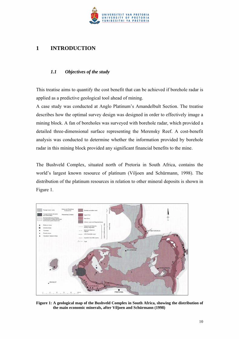
1 INTRODUCTION
1.1 Objectives of the study
This treatise aims to quantify the cost benefit that can be achieved if borehole radar is
applied as a predictive geological tool ahead of mining.
A case study was conducted at Anglo Platinum’s Amandelbult Section. The treatise
describes how the optimal survey design was designed in order to effectively image a
mining block. A fan of boreholes was surveyed with borehole radar, which provided a
detailed three-dimensional surface representing the Merensky Reef. A cost-benefit
analysis was conducted to determine whether the information provided by borehole
radar in this mining block provided any significant financial benefits to the mine.
The Bushveld Complex, situated north of Pretoria in South Africa, contains the
world’s largest known resource of platinum (Viljoen and Schürmann, 1998). The
distribution of the platinum resources in relation to other mineral deposits is shown in
Figure 1.
Figure 1: A geological map of the Bushveld Complex in South Africa, showing the distribution of the main economic minerals, after Viljoen and Schürmann (1998)
10
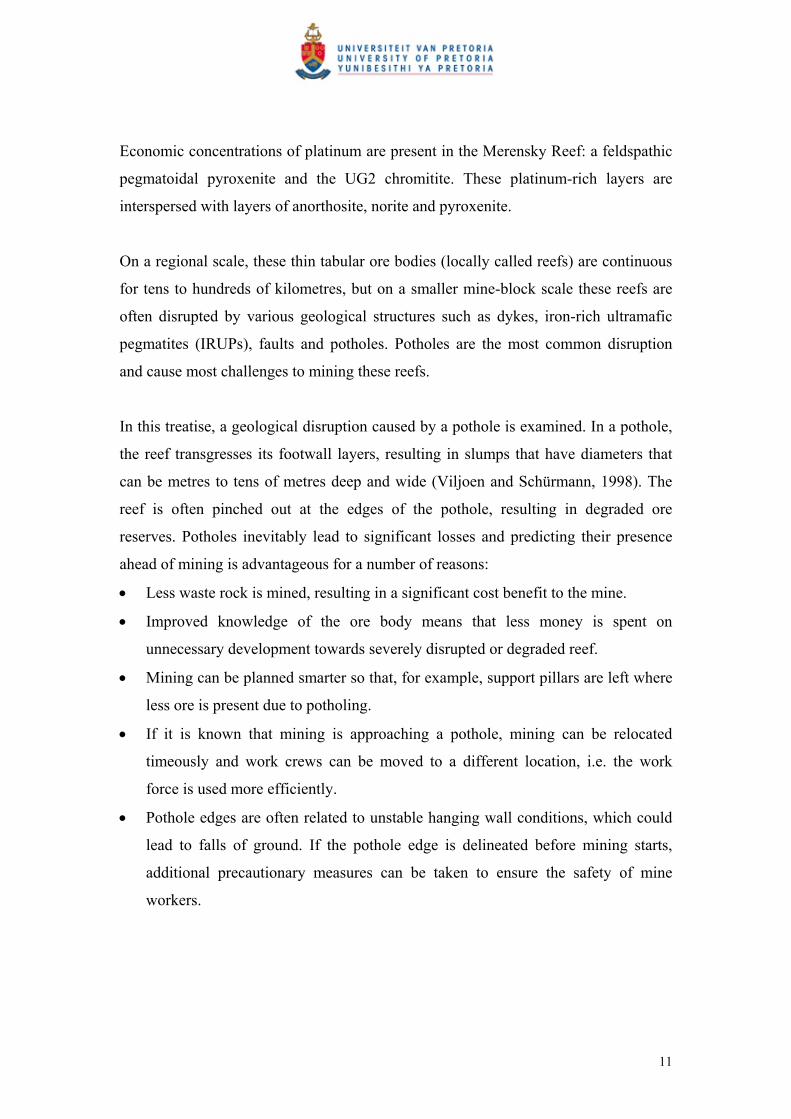
Economic concentrations of platinum are present in the Merensky Reef: a feldspathic
pegmatoidal pyroxenite and the UG2 chromitite. These platinum-rich layers are
interspersed with layers of anorthosite, norite and pyroxenite.
On a regional scale, these thin tabular ore bodies (locally called reefs) are continuous
for tens to hundreds of kilometres, but on a smaller mine-block scale these reefs are
often disrupted by various geological structures such as dykes, iron-rich ultramafic
pegmatites (IRUPs), faults and potholes. Potholes are the most common disruption
and cause most challenges to mining these reefs.
In this treatise, a geological disruption caused by a pothole is examined. In a pothole,
the reef transgresses its footwall layers, resulting in slumps that have diameters that
can be metres to tens of metres deep and wide (Viljoen and Schürmann, 1998). The
reef is often pinched out at the edges of the pothole, resulting in degraded ore
reserves. Potholes inevitably lead to significant losses and predicting their presence
ahead of mining is advantageous for a number of reasons:
Less waste rock is mined, resulting in a significant cost benefit to the mine.
Improved knowledge of the ore body means that less money is spent on
unnecessary development towards severely disrupted or degraded reef.
Mining can be planned smarter so that, for example, support pillars are left where
less ore is present due to potholing.
If it is known that mining is approaching a pothole, mining can be relocated
timeously and work crews can be moved to a different location, i.e. the work
force is used more efficiently.
Pothole edges are often related to unstable hanging wall conditions, which could
lead to falls of ground. If the pothole edge is delineated before mining starts,
additional precautionary measures can be taken to ensure the safety of mine
workers.
11

1.2 The Platmine Research Collaborative
The work presented here was conducted under the Platmine collaborative research
programme. This research programme, initiated in 2003, involves the Council for
Scientific and Industrial Research (CSIR), Anglo Platinum, Impala Platinum, Lonmin
Platinum and Northam Platinum. Its main focus is the long-term sustainability of the
platinum industry in South Africa. Among its primary goals listed at
www.platmine.co.za are:
To increase productivity.
To develop technologies and competencies to improve overall safety and
health.
To facilitate mechanisation by solving common technological problems.
To improve the underground working environment.
This treatise ties in with the first objective listed above, i.e. increasing productivity in
the platinum industry, but borehole radar is also increasingly being used in
conjunction with other geophysical methods to characterise the rock mass prior to
mining in order to pre-empt hazardous conditions.
1.3 Delimitations
It is important to note that this treatise will only deal with determining the elevation of
the Merensky Reef within the defined mining block. In particular, the position of the
bottom contact of the Merensky Reef is delineated.
This treatise assumes that the grade information pertaining to the Merensky Reef is
predictable and that grade variation is acceptable within the mining block. A constant
grade is used for financial calculations. This value is defined in Section 6.2.1.
12
2 BOREHOLE RADAR
Borehole radar is ground penetrating radar (GPR) applied from within a borehole.
GPR is a geophysical technique whereby radio waves are transmitted into the ground
to locate buried objects or hidden interfaces (Daniel et al., 2004). GPR measures
differences in the dielectric property permittivity, and the distance that radar waves
travel in a medium is determined by its conductivity (Du Pisani and Vogt, 2003).
A typical bi-static borehole radar instrument consists of separate transmitter and
receiver probes that are deployed inside a borehole. In this study, the CSIR’s
Aardwolf BR40 was used to acquire the borehole radar data. This instrument has a
centre frequency of 40 MHz and a vertical resolution of approximately 1 m (Vogt et
al., 2005). A schematic of the Aardwolf BR40 is shown in Figure 2.
Figure 2: Schematic for the Aardwolf BR40 instrument, showing the radar transmitter, receiver, optical-fibre links, winch and control unit (Vogt 2002)
Borehole radar can be applied in reflection mode from within a single borehole (Vogt,
2006) or in transmission mode, whereby the transmitter is located in one borehole and
the receiver in an adjacent borehole. In transmission mode, borehole radar can
determine whether conductive material is present between two boreholes (Turner et
al., 2000).
13
For the study presented in this treatise, borehole radar is used in single-borehole
reflection mode to image the boundary of the Merensky Reef within a section of
Anglo Platinum’s Amandelbult Section.
In borehole radar reflection mode, radar waves are transmitted into the rock mass and
the time taken for these waves to travel to a reflective interface is measured in
nanoseconds (Vogt et al., 2005). If the velocity of the radar waves in the rock mass is
known, the distance to the interface can be calculated.
In order for a reflection borehole radar survey to be successful, the following factors
are of importance (Vogt, 2006):
The borehole from which borehole radar is applied should be oriented parallel
or sub-parallel to the target to be imaged, as shown in Figure 3.
There should be a significant permittivity contrast between the target and its
host rocks.
The technique works best if the borehole is situated in a host rock that is
resistive and delineates a target that is conductive.
The reflective contact should be sharp as opposed to gradationally changing
into a different rock type.
More technical information about borehole radar will be discussed throughout this
treatise as it becomes necessary.
14
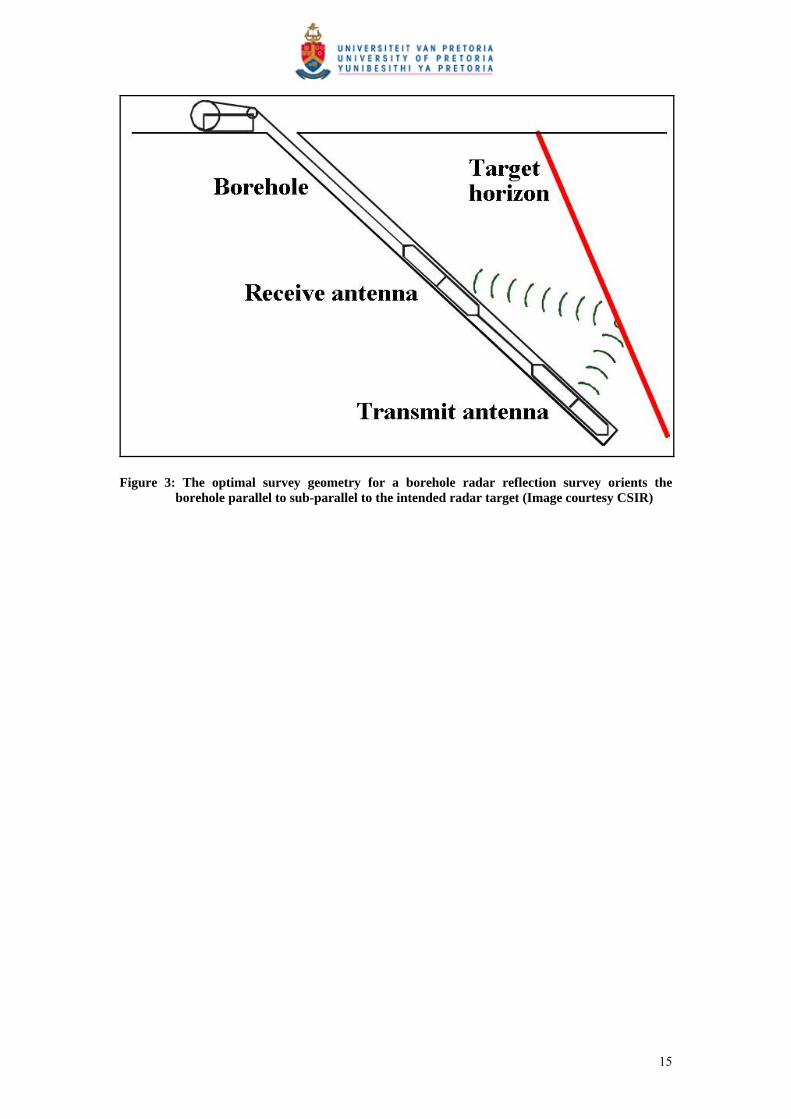
Figure 3: The optimal survey geometry for a borehole radar reflection survey orients the borehole parallel to sub-parallel to the intended radar target (Image courtesy CSIR)
15
3 THE MERENSKY REEF AT RPM AMANDELBULT
SECTION
3.1 Regional setting of RPM Amandelbult Section
Anglo Platinum’s Amandelbult Section is located in South Africa’s Limpopo
province (Figure 4). The mine is approximately 100 km north of Rustenburg and
40 km south of Thabazimbi. As seen in Figure 5, Amandelbult Section’s lease area is
in the shape of a rectangle with the long axis oriented NE-SW, and approximately
4 km wide on the short side and 20 km wide on the long side (Viljoen et al., 1986b).
The topography surrounding the mine is relatively flat and the surface is covered by a
thin layer of black turf soil. The only noticeable topography is a group of small hills to
the south of the main entrance of the mine, which are locally termed pyramid
gabbros. According to Viljoen et al. (1986b), these small hills form part of the
Bushveld Complex’s Main Zone, and they consist of gabbro-norite, which is the
prevalent rock type in the Main Zone of the Bushveld Complex.
To the west and north of Amandelbult Section, the quartzites of the Transvaal
Supergroup form the Witfontein Mountains. In the north-eastern part of the lease area,
the Crocodile River runs from south to north.
16

Figure 4: Locality plan showing Amandelbult Section in relation to the major geological rock types of the Bushveld Complex, after Viljoen et al., 1986b
Figure 5: Map of Amandelbult Section’s lease area, showing the main geological features and farm boundaries (Viljoen et al., 1986b)
17

3.2 History of the Amandelbult Mine
The Merensky Reef was discovered by A.F. Lombaard in 1924 (Viljoen et al.,
1986b). Although the Merensky Reef was discovered in the Eastern Bushveld, almost
all of the platinum mining that occurred up until the mid-Seventies in South Africa
was due to the extraction of the Merensky Reef in the Western Bushveld (Cawthorn,
1999).
The Merensky Reef was discovered in the Western Bushveld near Rustenburg in 1925
(Viljoen et al., 1986b), leading to more widespread exploration. Amandelbult Section
was prospected in 1926 by the Steelpoort Platinum Syndicate. Shortly thereafter,
ownership of Amandelbult transferred to Potgietersrust Platinum Limited, but interest
in the area decreased during the 1930s’ Depression, during which all platinum mining
was suspended.
Rustenburg Platinum Mines (RPM), which eventually became part of Anglo
Platinum, acquired the mineral rights for Amandelbult Section in 1964 and mining
eventually commenced on the farm Schilpadsnest in 1974 (Viljoen et al., 1986b).
Platinum production at Amandelbult ceased in 1975 due to a slump in the platinum
market, but after it restarted in 1976, production increased on a yearly basis
(www.platinummetalsreview.co.za).
Currently both the Merensky and UG2 reefs are mined at Amandelbult Section.
Amandelbult is expecting to increase the rate of equivalent refined platinum
production to approximately 625,000 ounces in 2007 (Anglo Platinum Annual Report
2006).
3.3 Regional Geology of the Merensky Reef
The Merensky Reef occurs in the Upper Critical Zone of the Bushveld Complex.
According to Viljoen (1999), the reef has been delineated for approximately 145 km
in the Western Lobe of the Bushveld Complex. Underground and opencast extraction
of the reef is taking place over a strike distance of approximately 90 km (Viljoen et
18

al., 1986b). The Merensky Reef’s dip changes from approximately 9° to 12° as it is
traced inwards towards the centre of the Bushveld Complex, with steeply dipping
exceptions in parts of the complex.
The thickness of the Merensky Reef can vary between 2 cm and 14 m (Viljoen et al.,
1986b). Its down-dip extension has been traced with the help of seismic surveys for
up to 50 km, and to depths of 6 km (Du Plessis and Kleinwegt, 1987). Since mining
on the Merensky Reef commenced in 1929, a large amount of data has been gathered
about this particular reef (Viljoen, 1999), and it is evident that the Merensky Reef
varies dramatically regionally with regard to geology, mineralogy and PGE-grade
distribution (Kinloch and Peyerl, 1990; Eales et al., 1993; Viljoen et al., 1986a;
1986b; Viljoen, 1994; Eales and Cawthorn, 1996; Viljoen and Schürmann, 1998).
Viljoen (1999) says the Merensky Reef is typically a heterogeneous pegmatoidal
feldspathic pyroxenite bounded by two thin chromitite layers, generally referred to as
Bottom Chromitite and Top Chromitite. Viljoen (1999) continues to say that PGE-
grades generally increase as the pegmatoidal nature of the reef increases.
This treatise does not examine grade distribution within the Merensky Reef, but
concentrates on delineating the position of the reef in three dimensions for mining
purposes.
3.4 Regional Geology of the Merensky Reef at Amandelbult Section
As seen in Figure 4, Amandelbult Section is located in the north-western lobe of the
Bushveld Complex (Viljoen et al., 1986b). The platiniferous layers, i.e. the Merensky
and UG2 reefs, occur within a portion of the Lower, Critical and Main zones of the
Bushveld Complex, with Upper Zone rocks above (Viljoen et al., 1986b). The Upper
Zone layers cut off the bottom three layers to the north and south of Amandelbult
Section, resulting in an area known as the “northern gap” located to the south of the
mine.
19
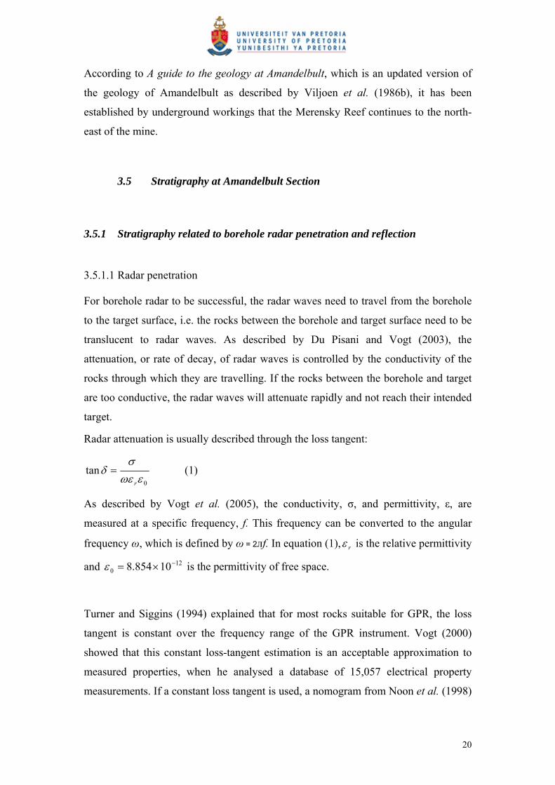
According to A guide to the geology at Amandelbult, which is an updated version of
the geology of Amandelbult as described by Viljoen et al. (1986b), it has been
established by underground workings that the Merensky Reef continues to the north-
east of the mine.
3.5 Stratigraphy at Amandelbult Section
3.5.1 Stratigraphy related to borehole radar penetration and reflection
3.5.1.1 Radar penetration For borehole radar to be successful, the radar waves need to travel from the borehole
to the target surface, i.e. the rocks between the borehole and target surface need to be
translucent to radar waves. As described by Du Pisani and Vogt (2003), the
attenuation, or rate of decay, of radar waves is controlled by the conductivity of the
rocks through which they are travelling. If the rocks between the borehole and target
are too conductive, the radar waves will attenuate rapidly and not reach their intended
target.
Radar attenuation is usually described through the loss tangent:
0
tan
r
(1)
As described by Vogt et al. (2005), the conductivity, σ, and permittivity, ε, are
measured at a specific frequency, f. This frequency can be converted to the angular
frequency ω, which is defined by ω = 2лf. In equation (1), r is the relative permittivity
and is the permittivity of free space. 120 10854.8
Turner and Siggins (1994) explained that for most rocks suitable for GPR, the loss
tangent is constant over the frequency range of the GPR instrument. Vogt (2000)
showed that this constant loss-tangent estimation is an acceptable approximation to
measured properties, when he analysed a database of 15,057 electrical property
measurements. If a constant loss tangent is used, a nomogram from Noon et al. (1998)
20

for a smooth planar reflector (Figure 6) can be used to predict with how many
wavelengths radar waves will penetrate into a rock with a given loss tangent.
Figure 6: Radar performance prediction for a smooth planar target after Noon et al. (1998)
Between 1980 and 2003, Vogt measured the electrical properties of approximately
4,500 rock samples, at a range of frequencies from 1 MHz to 64 MHz, using the rock
sample as a dielectric in a capacitor (Du Pisani and Vogt, 2003). Du Pisani and Vogt
(2003) used this database to calculate loss-tangent values for some of the Bushveld
Complex rocks related to the economic platinum horizons, i.e. anorthosite, norite and
pyroxenite. The loss-tangent values at a frequency of 64 MHz were used, as this was
closest to the centre frequency of the CSIR’s Aardwolf BR40 used for the case study
described in this treatise.
The distribution of the loss-tangent values for the three rock types are shown in Figure
7.
21
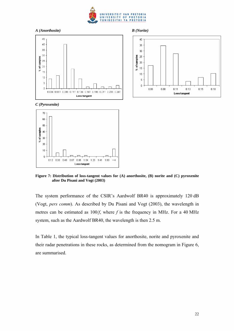
A (Anorthosite)
B (Norite)
C (Pyroxenite)
Figure 7: Distribution of loss-tangent values for (A) anorthosite, (B) norite and (C) pyroxenite after Du Pisani and Vogt (2003)
The system performance of the CSIR’s Aardwolf BR40 is approximately 120 dB
(Vogt, pers comm). As described by Du Pisani and Vogt (2003), the wavelength in
metres can be estimated as 100/f, where f is the frequency in MHz. For a 40 MHz
system, such as the Aardwolf BR40, the wavelength is then 2.5 m.
In Table 1, the typical loss-tangent values for anorthosite, norite and pyroxenite and
their radar penetrations in these rocks, as determined from the nomogram in Figure 6,
are summarised.
22

Table 1: The loss tangent and radar penetrations for anorthosite, norite and pyroxenite
Rock type Loss tangent Radar penetration
(wavelengths)
Radar penetration
(m)
Anorthosite 0.09 9 22.5
Norite 0.08 10 25
Pyroxenite 0.12 7 17.5
The radar penetrations shown in Table 1 are consistent with penetration achieved
during experimental and commercial surveys conducted from 2001 to 2007 with the
CSIR’s Aardwolf BR40 system (Vogt, et al., 2005; De Vries and Du Pisani, 2005).
3.5.1.2 Radar reflection Radar reflection is controlled by a difference in permittivity between two adjacent
materials though which the radar waves are travelling. According to Vogt et al.
(2005), this difference in permittivity influences how much of the radar signal is
reflected where two media border:
12
12
(2)
where 1 and 2 are the permittivities of medium 1 and medium 2 respectively. If
medium 2 is very conductive, 2 approaches infinity and the entire radar signal will be
reflected.
Du Pisani and Vogt (2003) compared the measured permittivity values of a number of
samples from across the Bushveld Complex for anorthosite, norite and pyroxenite.
The distribution of permittivity values for theses three rock types is shown in Figure
8.
23

A (Anorthosite)
B (Norite)
C (Pyroxenite)
Figure 8: The distribution of permittivity values for (A) anorthosite (B) norite and (C) pyroxenite at a radar frequency of 64 MHz after Du Pisani and Vogt (2003)
As seen in Figure 8, the permittivity values for anorthosite and norite are very similar,
hence the boundary between these two rock types is not expected to produce a
significant radar reflector. The permittivity contrast between pyroxenite and either
anorthosite or norite is much larger, and this boundary should produce a good radar
reflector.
3.5.1.3 Radar stratigraphy at Amandelbult Section The general stratigraphic column for the economic horizons at Amandelbult Section is
given in Figure 9. The borehole radar holes used in the case study described in
Section 5 were situated in the norite between the Merensky and Bastard reefs.
The distance that radar waves are expected to travel is indicated by the radar range
shown in Figure 9. During initial test surveys carried out at Amandelbult Section at
24

the start of the Platmine borehole radar project in 2002, it was found that the P2
marker was a highly conductive unit that limited the penetration of radar waves.
Hence radar waves are not expected to penetrate through the P2 marker.
In accordance with the findings presented by Du Pisani and Vogt (2003), the
following boundaries (Figure 9), within the radar range, are expected to reflect radar
waves:
Reflector 1: Boundary between P2 marker (feldspathic harzburgite) and the
norite above it.
Reflector 2: Boundary between footwall mottled anorthosite and Merensky
Reef.
Reflector 3: Boundary between anorthosite and Bastard Reef (poikilitic
pyroxenite).
Figure 9: General stratigraphic column for Amandelbult Section, showing the position of the borehole radar holes, the expected radar reflectors and the range of the borehole radar instrument (stratigraphic column from A guide to the geology of Amandelbult)
25
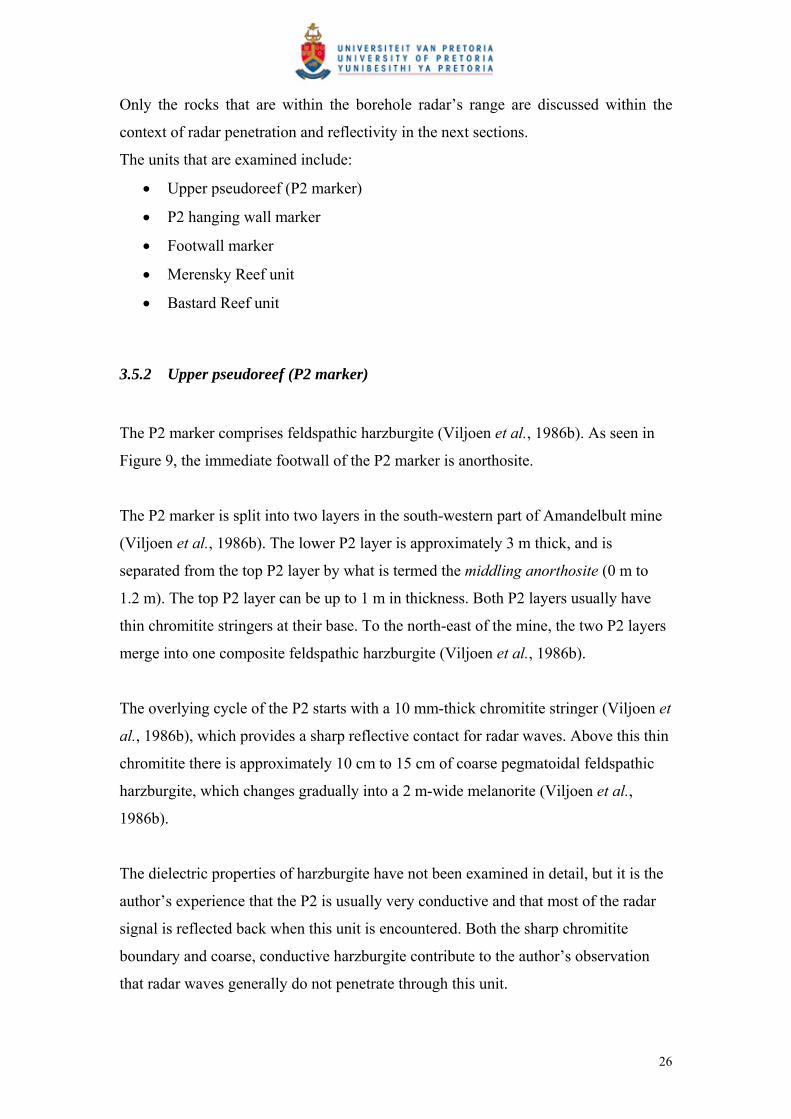
Only the rocks that are within the borehole radar’s range are discussed within the
context of radar penetration and reflectivity in the next sections.
The units that are examined include:
Upper pseudoreef (P2 marker)
P2 hanging wall marker
Footwall marker
Merensky Reef unit
Bastard Reef unit
3.5.2 Upper pseudoreef (P2 marker)
The P2 marker comprises feldspathic harzburgite (Viljoen et al., 1986b). As seen in
Figure 9, the immediate footwall of the P2 marker is anorthosite.
The P2 marker is split into two layers in the south-western part of Amandelbult mine
(Viljoen et al., 1986b). The lower P2 layer is approximately 3 m thick, and is
separated from the top P2 layer by what is termed the middling anorthosite (0 m to
1.2 m). The top P2 layer can be up to 1 m in thickness. Both P2 layers usually have
thin chromitite stringers at their base. To the north-east of the mine, the two P2 layers
merge into one composite feldspathic harzburgite (Viljoen et al., 1986b).
The overlying cycle of the P2 starts with a 10 mm-thick chromitite stringer (Viljoen et
al., 1986b), which provides a sharp reflective contact for radar waves. Above this thin
chromitite there is approximately 10 cm to 15 cm of coarse pegmatoidal feldspathic
harzburgite, which changes gradually into a 2 m-wide melanorite (Viljoen et al.,
1986b).
The dielectric properties of harzburgite have not been examined in detail, but it is the
author’s experience that the P2 is usually very conductive and that most of the radar
signal is reflected back when this unit is encountered. Both the sharp chromitite
boundary and coarse, conductive harzburgite contribute to the author’s observation
that radar waves generally do not penetrate through this unit.
26
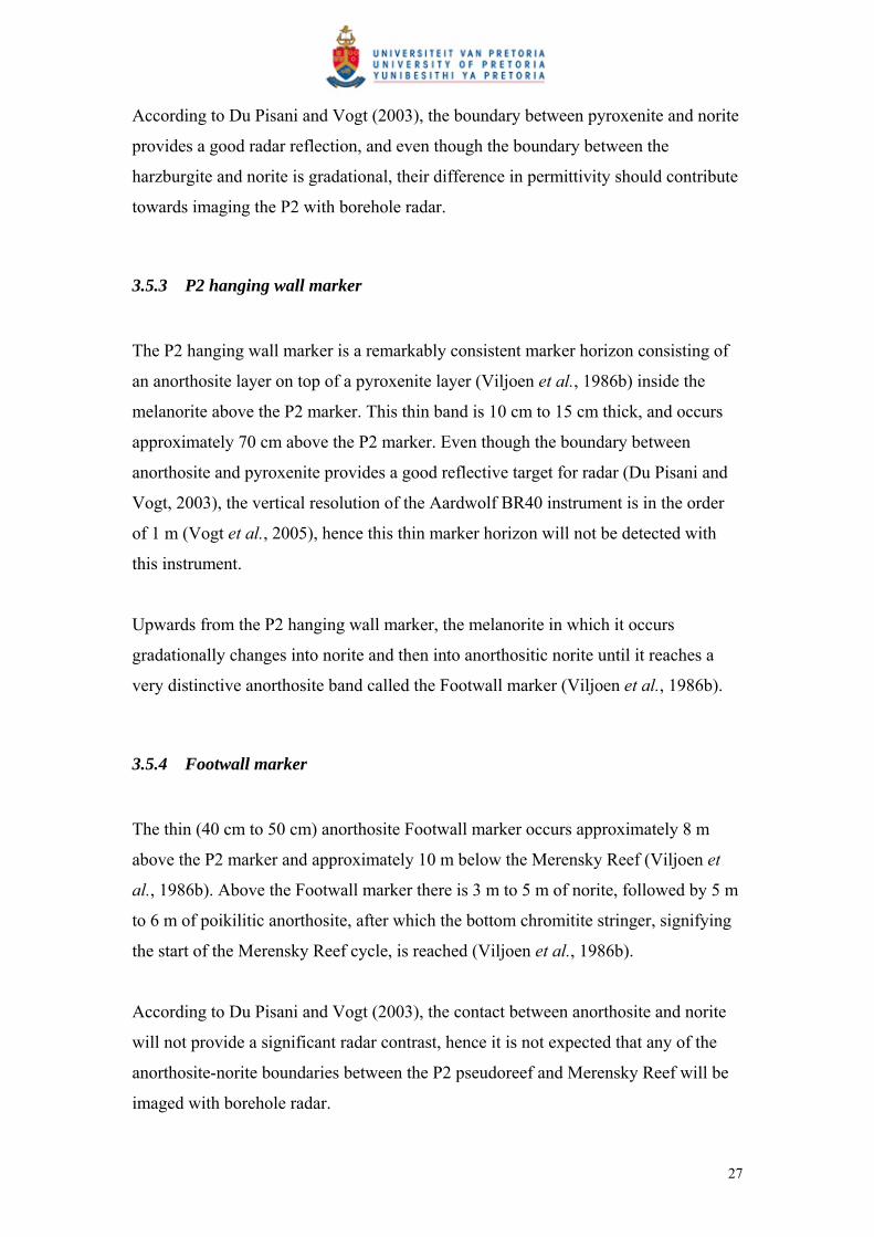
According to Du Pisani and Vogt (2003), the boundary between pyroxenite and norite
provides a good radar reflection, and even though the boundary between the
harzburgite and norite is gradational, their difference in permittivity should contribute
towards imaging the P2 with borehole radar.
3.5.3 P2 hanging wall marker
The P2 hanging wall marker is a remarkably consistent marker horizon consisting of
an anorthosite layer on top of a pyroxenite layer (Viljoen et al., 1986b) inside the
melanorite above the P2 marker. This thin band is 10 cm to 15 cm thick, and occurs
approximately 70 cm above the P2 marker. Even though the boundary between
anorthosite and pyroxenite provides a good reflective target for radar (Du Pisani and
Vogt, 2003), the vertical resolution of the Aardwolf BR40 instrument is in the order
of 1 m (Vogt et al., 2005), hence this thin marker horizon will not be detected with
this instrument.
Upwards from the P2 hanging wall marker, the melanorite in which it occurs
gradationally changes into norite and then into anorthositic norite until it reaches a
very distinctive anorthosite band called the Footwall marker (Viljoen et al., 1986b).
3.5.4 Footwall marker
The thin (40 cm to 50 cm) anorthosite Footwall marker occurs approximately 8 m
above the P2 marker and approximately 10 m below the Merensky Reef (Viljoen et
al., 1986b). Above the Footwall marker there is 3 m to 5 m of norite, followed by 5 m
to 6 m of poikilitic anorthosite, after which the bottom chromitite stringer, signifying
the start of the Merensky Reef cycle, is reached (Viljoen et al., 1986b).
According to Du Pisani and Vogt (2003), the contact between anorthosite and norite
will not provide a significant radar contrast, hence it is not expected that any of the
anorthosite-norite boundaries between the P2 pseudoreef and Merensky Reef will be
imaged with borehole radar.
27

3.5.5 Merensky Reef unit
The Merensky Reef can vary significantly regionally (Viljoen, 1999), but it is broadly
defined as “a mineralised zone within the ultramafic cumulate at the base of the
Merensky cyclic unit” (Viljoen and Schürmann, 1998). The Merensky Reef is
typically a heterogeneous pegmatoidal feldspathic pyroxenite (Viljoen and
Schürmann, 1998), which may contain various sulphides such as pyrrhotite,
pendlandite and chalcopyrite (Viljoen et al., 1986b). The boundaries of the Merensky
Reef are generally characterised by narrow (approximately 1 cm thick) chromitite
stringers (Viljoen and Schürmann 1998).
At Amandelbult Section, the bottom chromitite stringer below the Merensky Reef is
typically 5 mm to 15 mm thick (Viljoen et al., 1986b). The contact with the
underlying mottled anorthosite is usually very sharp, providing an excellent reflective
surface for borehole radar.
The lower chromitite stringer then grades upwards into the pegmatoidal feldspathic
pyroxenite and harzburgite of the Merensky Reef (Viljoen et al., 1986b). According to
Du Pisani and Vogt (2003), the boundary between anorthosite and pyroxenite has a
significant permittivity contrast and it is expected that the chromitite stringer on this
boundary will also contribute towards strengthening the dielectric contrast. Hence the
bottom of contact of the Merensky Reef is expected to provide a strong radar
reflector.
At Amandelbult Section, the Merensky Reef package can vary in thickness between
0 m and 5 m. Since the vertical resolution of the borehole radar instrument used in this
study is approximately 1 m, it is expected that the Merensky Reef will only be imaged
where it is thicker than 1 m. In the author’s experience, however, layers thinner than
1 m have been imaged using 40 MHz to 50 MHz borehole radars, especially where a
significant contrast in the permittivity was present between two layers (Chalke et al.,
2006). Since there is a significant contrast between the Merensky Reef and its
underlying layers, together with the sharp chromitite boundary, it is expected that the
Merensky Reef will be imaged even where it is thinner than 1 m.
28

The top contact of the Merensky Reef is also characterised by a thin chromitite layer,
which is normally not thicker than 20 mm (Viljoen et al., 1986b). Above this
chromitite stringer there is a thin layer of poikilitic feldspathic pyroxenite which
gradationally changes into norite (Viljoen et al., 1986b).
Since the contact between the Merensky Reef pyroxenite and its overlying pyroxenite
is essentially a contact between two similar rock types, the top Merensky Reef contact
is not expected to be a good radar reflector. Furthermore, the hanging wall pyroxenite
above the top Merensky chromitite stringer grades into norite and although the
boundary between pyroxenite and norite provides a good radar reflector (Du Pisani
and Vogt, 2003) due to the gradational transition, a radar reflection is not expected.
The norite layer above the Merensky Reef is topped by a prominent mottled
anorthosite, which is 2 m to 3 m thick (Viljoen et al., 1986b). According to Du Pisani
and Vogt (2003), the boundary between norite and anorthosite does not have enough
of a dielectric contrast to produce a radar reflection.
The entire Merensky Reef cyclic unit from the pegmatoidal pyroxenite to the mottled
anorthosite is typically approximately 16 m thick (Viljoen et al., 1986b).
3.5.6 Bastard Reef unit
The Bastard Reef cyclic unit is very similar to the Merensky Reef cyclic unit, except
that this cycle is spread over a thickness of 32 m, where the Merensky unit is 16 m
thick (Viljoen et al., 1986b). The lower portion of the Bastard Reef cycle does not
contain pegmatoidal pyroxenite and it is also not characterised by a thin chromitite
base (Viljoen et al., 1986b). Instead, the Bastard Reef usually consists of a fine-
grained pyroxenite that changes gradationally into norite.
Since the poikilitic pyroxenite at the base of the Bastard Reef unit has a sharp contact
with the underlying mottled anorthosite, this contact should produce a good radar
29

reflection. According to Du Pisani and Vogt (2003), the contact between anorthosite
and pyroxenite will produce a good radar reflection.
3.5.7 Notes on the UG2 chromitite
As seen in Figure 10 when normal Merensky Reef is present, the UG2 chromitite is
expected 38.3 m beneath the Merensky Reef. The radar waves are not expected to
travel all the way from the borehole (drilled in Merensky Reef footwall norite) to the
UG2 due to two reasons:
1. The UG2 is too far from the borehole.
2. The feldspathic harzburgite P2 marker is expected to attenuate the radar
signal.
In order to evaluate the topography of the UG2 Reef with borehole radar, new radar
boreholes would have to be drilled below the P2 marker.
30
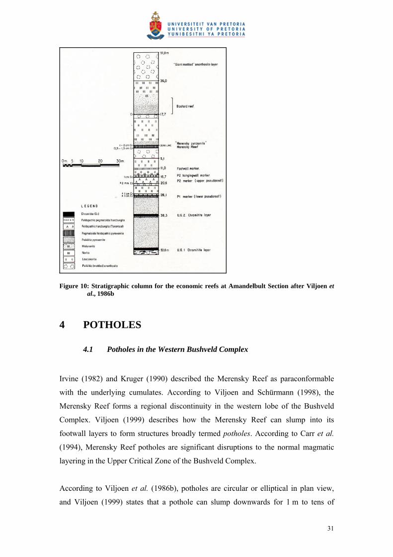
Figure 10: Stratigraphic column for the economic reefs at Amandelbult Section after Viljoen et al., 1986b
4 POTHOLES
4.1 Potholes in the Western Bushveld Complex
Irvine (1982) and Kruger (1990) described the Merensky Reef as paraconformable
with the underlying cumulates. According to Viljoen and Schürmann (1998), the
Merensky Reef forms a regional discontinuity in the western lobe of the Bushveld
Complex. Viljoen (1999) describes how the Merensky Reef can slump into its
footwall layers to form structures broadly termed potholes. According to Carr et al.
(1994), Merensky Reef potholes are significant disruptions to the normal magmatic
layering in the Upper Critical Zone of the Bushveld Complex.
According to Viljoen et al. (1986b), potholes are circular or elliptical in plan view,
and Viljoen (1999) states that a pothole can slump downwards for 1 m to tens of
31
metres. It is also possible for the Merensky Reef to transgress downwards in a step-
like fashion (Viljoen and Schürmann, 1998), with steps associated with steep portions
of thin contact reef. As the reef cascades downwards, it is also possible for
mineralised reef to form on various footwall units (Viljoen and Schürmann, 1998).
Various types of pothole structures and pothole reefs have been classified and
identified (Farquar, 1986; Leeb du Toit, 1986; Viljoen and Hieber, 1986; Kinloch and
Peyerl, 1990; Viljoen et al., 1986a; 1986b; Schürmann, 1991).
Wagner (1929) divided the Western Bushveld Complex rocks into the Rustenburg
facies to the south of Pilanesberg and the Swartklip facies to the north. These two
facies were then sub-divided into subfacies, which can, among other things, be
distinguished by the abundance, size and type of potholes present (Figure 11).
32

Figure 11: Merensky Reef facies map for the Western Bushveld Complex, after Viljoen and Schürmann (1998)
4.2 Potholes at Amandelbult Section
According to Viljoen et al. (1986b), potholes at Amandelbult Section are similar to
potholes elsewhere in the Bushveld Complex in that the Merensky Reef and its
hanging wall plunge abruptly and transgress their footwall layers.
33

Viljoen et al. (1986b), documented the potholes they were aware of at Amandelbult
Section, according to their size, shape and distribution, as shown in Figure 12.
Figure 12: Distribution of pothole structures and isopach map for normal Merensky Reef at Amandelbult Section after Viljoen et al., 1986b
According to Viljoen (1994), a local, rapid thinning of the Merensky Reef is evident
towards the edges of individual potholes, especially at Amandelbult Section (Figure
13). Viljoen et al. (1986b), state that contact-type reef is usually developed around
and on the edges of potholes. They further describe how the top and bottom chromitite
stringers associated with the top and bottom contacts of the normal Merensky Reef
converge and can even merge into a single chromitite layer with hanging wall
poikilitic pyroxenite above and footwall mottled anorthosite below. This thin
chromitite contact is called contact reef (Viljoen, 1994) and according to Viljoen et al.
(1986b), it can transgress downwards and cut across the footwall succession. This
contact reef may be mineralised, but due to its unpredictable behaviour and thinness,
it is often not viable to mine it (Viljoen et al., 1986b).
At the base of the pothole structure, the contact-type reef approaches the upper
pseudoreef or P2 (Viljoen et al., 1986b). Here, pegmatoidal feldspathic pyroxenite,
which is very similar to normal Merensky Reef, occurs directly above the P2. This
reef is called pothole reef and it is typically about 16 m below the normal Merensky
Reef elevation (Viljoen, 1994). The generalised pothole model as given in A guide to
34
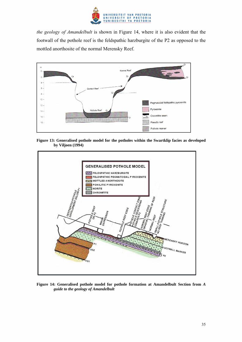
the geology of Amandelbult is shown in Figure 14, where it is also evident that the
footwall of the pothole reef is the feldspathic harzburgite of the P2 as opposed to the
mottled anorthosite of the normal Merensky Reef.
Figure 13: Generalised pothole model for the potholes within the Swartklip facies as developed by Viljoen (1994)
Figure 14: Generalised pothole model for pothole formation at Amandelbult Section from A guide to the geology of Amandelbult
35

4.3 The influence of potholes on mining
4.3.1 Mining of the Merensky Reef at Amandelbult Section
The Merensky Reef topography is initially estimated by extrapolating reef
intersections from deep exploration boreholes. From these boreholes, the general dip
and strike of the ore body is approximated. 3D-Seismic surveys from the surface
provide a more continuous picture of the Merensky Reef and valuable information on
large potholes and structures that could negatively affect the positioning of expensive
capital expenditure such as main and ventilation shafts.
Thin Merensky Reef types are generally mined by narrow (80cm to 100cm)
conventional breast stoping methods (Viljoen, 1994). From deep vertical shafts sunk
through the ore body, haulages are developed parallel to the strike of the reef,
approximately 30 m below it (Figure 15). Horizontal cross-cuts are then developed
towards the dipping reef plane (Figure 16A). Raise lines are excavated in the dip
direction on the reef elevation (Figure 16B). Mining then commences in panels, with
face widths of typically 35 m, from opposite raises (Figure 16C). At the end of the
mining process, a natural dip pillar is left in the middle of the mining block to provide
support.
In the case study presented in this treatise, borehole radar was used to delineate a
mining block bounded by two cross-cuts and a haulage, i.e. a block of approximately
200 m by 200 m.
36
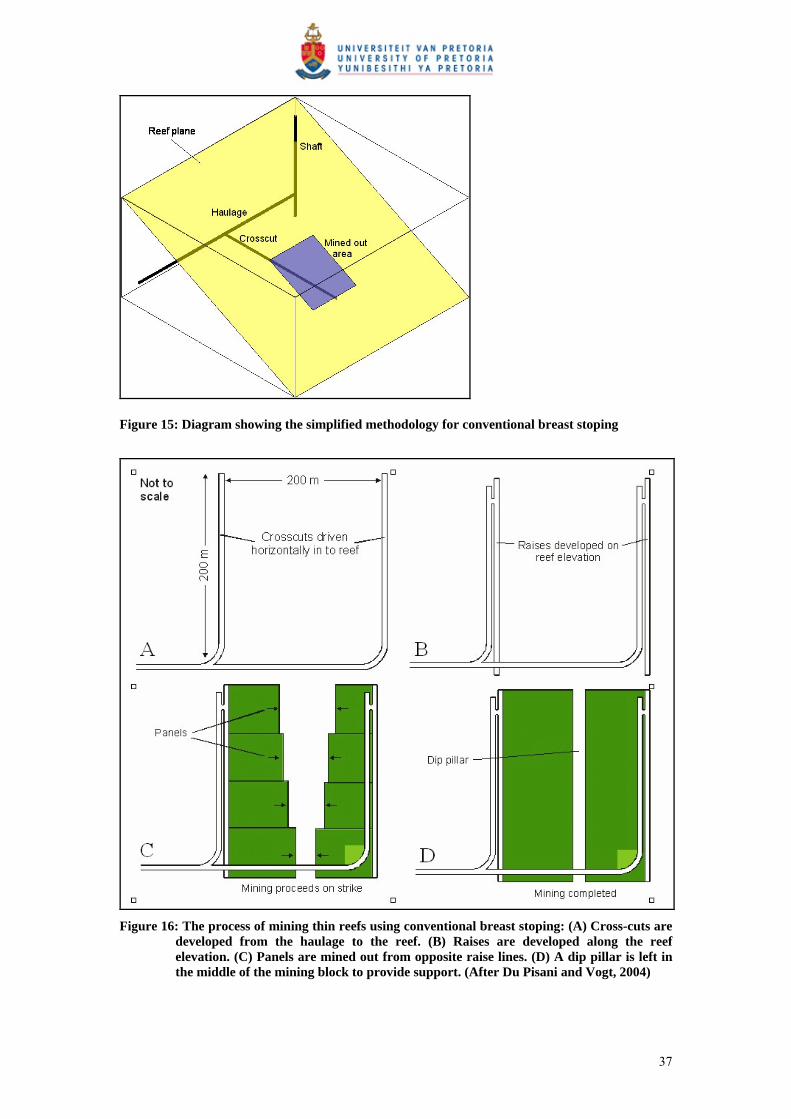
Figure 15: Diagram showing the simplified methodology for conventional breast stoping
Figure 16: The process of mining thin reefs using conventional breast stoping: (A) Cross-cuts are
developed from the haulage to the reef. (B) Raises are developed along the reef elevation. (C) Panels are mined out from opposite raise lines. (D) A dip pillar is left in the middle of the mining block to provide support. (After Du Pisani and Vogt, 2004)
37

4.3.2 Influence of potholes in mining the Merensky Reef at Amandelbult Section
According to Viljoen (1994), for normal Merensky Reef within the Swartklip facies,
which is up to 150 cm thick, the entire reef package is mined together with its
bounding chromitite stringers.
If the reef is thicker than 150 cm, the position of the mining cut is based upon the
vertical grade distribution of the Merensky Reef as described by Viljoen (1994).
Viljoen (1994) states that for the Merensky Reef within the Swartklip facies (thicker
than 150 cm), it is usually the top portion of the reef package that is mined, and that
the bottom pegmatoidal portion and lower chromitite band are left behind.
Potholes in the Swartklip facies are usually identified from local thinning and,
according to Viljoen (1994), the proximity to a pothole can potentially be inferred by
monitoring reef thickness and gradient. As pothole reef typically occurs
approximately 16 m below the normal Merensky Reef elevation (Viljoen, 1994), mine
excavations need to be redeveloped at a lower elevation to access portions of pothole
reef.
Viljoen (1994) advises that an assessment be made of the pothole reef, and the
intermediary contact reef between the normal and pothole reef, before mining
decisions are concluded. He states that due to the irregularity and unpredictable nature
of the contact reef, it is regularly unmineable, and that if a long section of irregular
contact reef is present between the normal and pothole reef, it will lead to a section of
total reef loss.
According to the on-shaft geologist (Marais, pers comm) at the time of the borehole
radar surveys, current practice for predicting potholes is:
Outlines of potholes are based on information gathered from the surface as
well as underground drilling and mapping in stope panels.
When a pothole is intersected in an underground borehole, a fan of boreholes
is drilled in order to determine the extent of the pothole.
38

In ideal situations the miners notify the geologist as soon as they encounter a
pothole in the stope. If a pothole is detected in the stope, the geologist goes to
that working area and tries to map it, and then plots it on to the 1:1000
working plans for that area.
The interpretation of geological structures on the working plans is always a
combination of information from boreholes and underground mapping.
At Amandelbult Section, a pothole is considered significant when it fills up one-third
of a mining panel, i.e. it has a diameter of roughly 10 m to 12 m. According to Marais
(pers comm), miners are supposed to notify the geologist as soon as they intersect a
pothole while stoping. Once the miners have notified the geologist of a pothole
intersection, he will then visit the panel and make a recommendation either to stop the
panel, if the pothole is large enough, or to advance until such a time that the panel
comprises one-third of the total panel length. The geologist’s recommendations are
put in writing and sent to the production manager, section manager, mine overseer and
shift supervisor, as well as the shaft surveyor and shaft rock engineer. Transgression
of the geologist’s recommendations could be liable to disciplinary procedures. Marais
(pers comm) stresses that the above scenario is the ideal situation. He further states
that miners are compensated per square metre advanced and not for ounces of PGE-
minerals delivered to the processing plant, and that in some cases miners will not
disclose that they have encountered a pothole. In such a case, waste material will then
be sent to the plant. Daily reports from the plant will immediately alert managers
when the head grade drops significantly. When this happens, “grade raids” are done
by the surveyors and geologists, during which all stope panels will be visited within
the space of two days to check for off-reef mining.
Marais (pers comm) does, however, say that generally there is good cooperation
between most miners and their line management and that tools such as
photogrammetry (a photographic report of sample sections) could alert the geologist
to the existence of a pothole on a panel. The geologist will then investigate and report
on his findings.
39
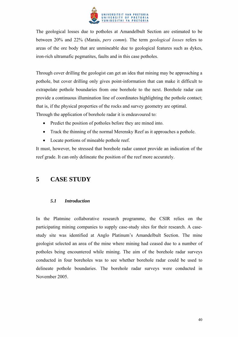
The geological losses due to potholes at Amandelbult Section are estimated to be
between 20% and 22% (Marais, pers comm). The term geological losses refers to
areas of the ore body that are unmineable due to geological features such as dykes,
iron-rich ultramafic pegmatites, faults and in this case potholes.
Through cover drilling the geologist can get an idea that mining may be approaching a
pothole, but cover drilling only gives point-information that can make it difficult to
extrapolate pothole boundaries from one borehole to the next. Borehole radar can
provide a continuous illumination line of coordinates highlighting the pothole contact;
that is, if the physical properties of the rocks and survey geometry are optimal.
Through the application of borehole radar it is endeavoured to:
Predict the position of potholes before they are mined into.
Track the thinning of the normal Merensky Reef as it approaches a pothole.
Locate portions of mineable pothole reef.
It must, however, be stressed that borehole radar cannot provide an indication of the
reef grade. It can only delineate the position of the reef more accurately.
5 CASE STUDY
5.1 Introduction
In the Platmine collaborative research programme, the CSIR relies on the
participating mining companies to supply case-study sites for their research. A case-
study site was identified at Anglo Platinum’s Amandelbult Section. The mine
geologist selected an area of the mine where mining had ceased due to a number of
potholes being encountered while mining. The aim of the borehole radar surveys
conducted in four boreholes was to see whether borehole radar could be used to
delineate pothole boundaries. The borehole radar surveys were conducted in
November 2005.
40

5.2 Borehole radar survey design
The survey design was based on delineating a mining block defined by the area
between two cross-cuts (or raise lines) and the haulage from which these cross-cuts
were developed.
A number of survey layouts were considered. The survey layout needed to:
Cover as much of the mining block as possible.
Eliminate the necessity for developing too many cubbies from which to drill
the boreholes required for borehole radar.
Some of the survey designs that were considered are shown in Figure 17.
Designs A to D were all deemed impractical due to the fact that the drill rig would
have to be moved a number of times in order to drill all the boreholes required to
cover the mining block. Using more than one drill rig to drill holes simultaneously
was also considered impractical for a test study, since drill rigs were being used for
other drilling purposes (such as cover drilling) in other sections of the mine.
It was decided that drilling a fan of boreholes from a single cubby as seen in Figure
17E, some distance along a cross-cut, would provide sufficient cover of the mining
block and eliminate having to move the drill rig unnecessarily. The two boreholes
numbered 1 and 8 were eliminated from the plan, because they would be too close to
the cross-cut, and the reflection produced by the cross-cut would mask reflections
produced by the reef.
41

Figure 17: Borehole layouts considered for the borehole radar case study at Amandelbult Section. The arrowed lines indicate possible borehole positions.
The radar boreholes were drilled at Amandelbult 10-Level, from 9W cross-cut.
Access was only available from one cross-cut, hence only one fan of boreholes was
drilled, aiming to cover the entire block bounded by 9W and 8W cross-cuts by using
longer boreholes as planned in Figure 17E. The survey layout is shown in plan in
Figure 18, where the red lines represent the borehole radar holes and the purple dots
represent some of the geological boreholes drilled for reef intersection within the area.
The radar boreholes were planned to cover the entire mining block bounded by 9W
and 8W cross-cuts on 10-Level. The boreholes were drilled up to 250 m each, in order
to provide the required coverage, but due to operational problems and borehole
blockages, not one of the holes were surveyed with borehole radar up to 250 m. The
coverage provided by the actual radar survey lengths is represented in Figure 18.
42
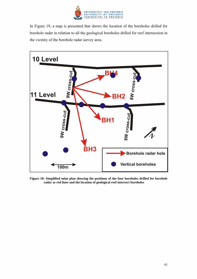
In Figure 19, a map is presented that shows the location of the boreholes drilled for
borehole radar in relation to all the geological boreholes drilled for reef intersection in
the vicinity of the borehole radar survey area.
Figure 18: Simplified mine plan showing the positions of the four boreholes drilled for borehole radar as red lines and the location of geological reef intersect boreholes
43
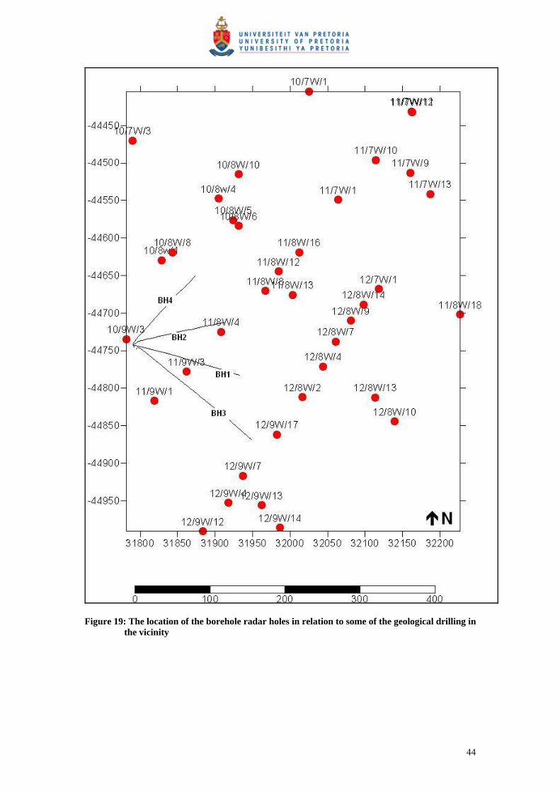
Figure 19: The location of the borehole radar holes in relation to some of the geological drilling in the vicinity
44
The boreholes were drilled in the norite between the Merensky and Bastard reefs (see
the stratigraphic column in Figure 9). As described in Section 3, the bottom contacts
of both the Merensky and Bastard reefs are expected to produce radar reflections.
The boreholes were angled away from the Merensky Reef and towards the Bastard
Reef so that these two reflectors could be distinguishable on the radargrams. A
radargram acquired for borehole 1 is shown in Figure 20A to demonstrate how the
two radar reflectors produced by the Merensky and Bastard reefs could be
distinguished from one another. At the collar of borehole 1, it is close to the Merensky
Reef and far from the Bastard Reef. As we progress along the borehole, the borehole
moves further away from the Merensky Reef and closer to the Bastard Reef. Hence,
the Merensky Reef reflector on the radargram starts close to the borehole position at
0m along the x-axis, and moves further away from the borehole position as we
progress along the borehole. The Bastard Reef reflector starts far from the borehole
position at its collar and moves closer to the borehole. Both reflectors manifest within
the two-dimensional space of the radargram as a function of their distance away from
the borehole.
Figure 20B provides a schematic showing the positions of the Bastard and Merensky
reefs above and below the borehole respectively.
45
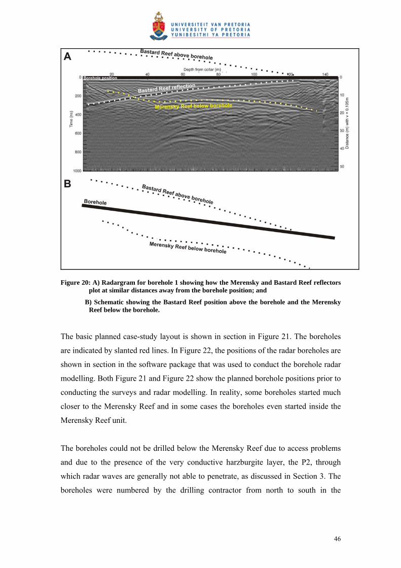
Figure 20: A) Radargram for borehole 1 showing how the Merensky and Bastard Reef reflectors plot at similar distances away from the borehole position; and
B) Schematic showing the Bastard Reef position above the borehole and the Merensky Reef below the borehole.
The basic planned case-study layout is shown in section in Figure 21. The boreholes
are indicated by slanted red lines. In Figure 22, the positions of the radar boreholes are
shown in section in the software package that was used to conduct the borehole radar
modelling. Both Figure 21 and Figure 22 show the planned borehole positions prior to
conducting the surveys and radar modelling. In reality, some boreholes started much
closer to the Merensky Reef and in some cases the boreholes even started inside the
Merensky Reef unit.
The boreholes could not be drilled below the Merensky Reef due to access problems
and due to the presence of the very conductive harzburgite layer, the P2, through
which radar waves are generally not able to penetrate, as discussed in Section 3. The
boreholes were numbered by the drilling contractor from north to south in the
46
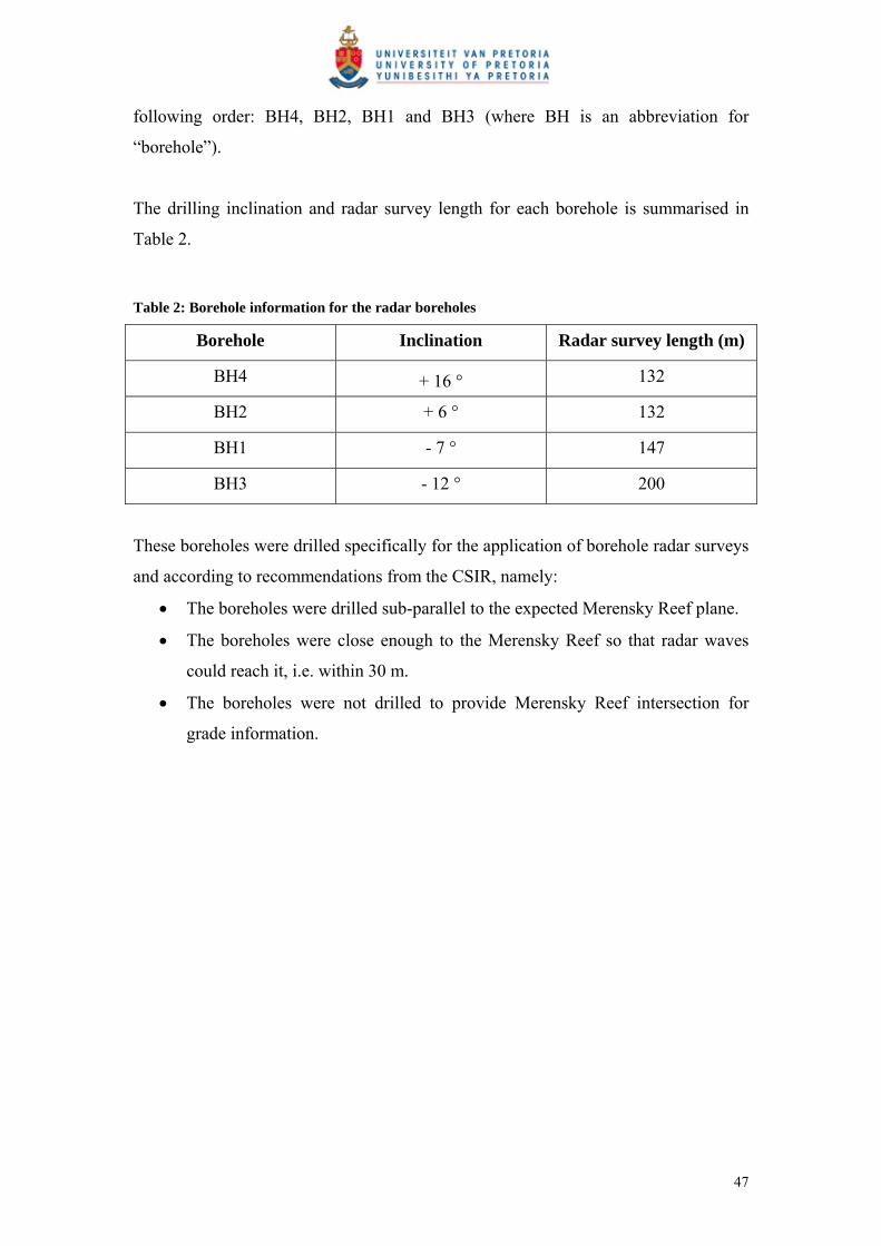
following order: BH4, BH2, BH1 and BH3 (where BH is an abbreviation for
“borehole”).
The drilling inclination and radar survey length for each borehole is summarised in
Table 2.
Table 2: Borehole information for the radar boreholes
Borehole Inclination Radar survey length (m)
BH4 + 16 ° 132
BH2 + 6 ° 132
BH1 - 7 ° 147
BH3 - 12 ° 200
These boreholes were drilled specifically for the application of borehole radar surveys
and according to recommendations from the CSIR, namely:
The boreholes were drilled sub-parallel to the expected Merensky Reef plane.
The boreholes were close enough to the Merensky Reef so that radar waves
could reach it, i.e. within 30 m.
The boreholes were not drilled to provide Merensky Reef intersection for
grade information.
47

Not according to scale
Figure 21: Schematic showing the case-study layout in section (looking from the east), with the boreholes (red lines) drilled between the Bastard and Merensky reefs, with boreholes angled towards the Bastard Reef
Figure 22: Case-study layout in section, showing radar boreholes as observed from the west. This
is the hypothetical base model with flat surfaces for the Merensky and Bastard reefs.
48
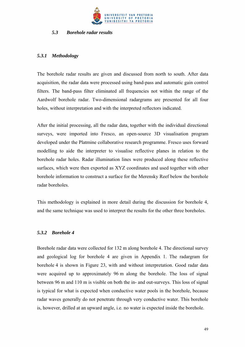
5.3 Borehole radar results
5.3.1 Methodology
The borehole radar results are given and discussed from north to south. After data
acquisition, the radar data were processed using band-pass and automatic gain control
filters. The band-pass filter eliminated all frequencies not within the range of the
Aardwolf borehole radar. Two-dimensional radargrams are presented for all four
holes, without interpretation and with the interpreted reflectors indicated.
After the initial processing, all the radar data, together with the individual directional
surveys, were imported into Fresco, an open-source 3D visualisation program
developed under the Platmine collaborative research programme. Fresco uses forward
modelling to aide the interpreter to visualise reflective planes in relation to the
borehole radar holes. Radar illumination lines were produced along these reflective
surfaces, which were then exported as XYZ coordinates and used together with other
borehole information to construct a surface for the Merensky Reef below the borehole
radar boreholes.
This methodology is explained in more detail during the discussion for borehole 4,
and the same technique was used to interpret the results for the other three boreholes.
5.3.2 Borehole 4
Borehole radar data were collected for 132 m along borehole 4. The directional survey
and geological log for borehole 4 are given in Appendix 1. The radargram for
borehole 4 is shown in Figure 23, with and without interpretation. Good radar data
were acquired up to approximately 96 m along the borehole. The loss of signal
between 96 m and 110 m is visible on both the in- and out-surveys. This loss of signal
is typical for what is expected when conductive water pools in the borehole, because
radar waves generally do not penetrate through very conductive water. This borehole
is, however, drilled at an upward angle, i.e. no water is expected inside the borehole.
49

The geological log for borehole 4 (Appendix 1) shows that iron-replacement was
logged in the borehole between 97.4 m and 97.87 m and then again between 103.34 m
and 106.56 m. Iron-replacement is very conductive, and it would explain the signal
loss seen on the radargram.
In Figure 23, two radargrams are presented for the borehole radar survey conducted in
borehole 4. The top radargram is the radar data after initial filtering. The bottom
radargram is the same, but the two prominent radar reflectors, namely those produced
from the Merensky and Bastard reefs, are annotated. The Bastard Reef reflection is
shown as a white dotted line on the bottom radargram in Figure 23 and is interpreted
to be in this position due to the fact that it intersects the borehole at approximately
100 m along the borehole, which is consistent with Bastard Reef logged in the drill
core at this position. The Merensky Reef reflection is shown as a yellow dotted line in
Figure 23. It is not as clear as the Bastard Reef reflection, and its position was
interpreted as a result of Merensky Reef pyroxenite logged at the start of the borehole
as well as a discussion with the mine geologist, where the most likely position of the
Merensky Reef was ascertained. The very straight reflector seen between
approximately 50 m and 90 m, starting at a distance of 40 m away from the borehole
and moving towards it, is typical of the signature that a near-vertical structure
intersecting the borehole would produce. A number of fractures are logged in the
borehole between 108 m and 118 m (geological log in (Appendix 1). One of these
fractures may be producing this radar reflection.
After the initial 2D interpretation presented in Figure 23, the radargram for borehole 4
was imported into the 3D visualisation software package Fresco to have a look at
borehole radar data in 3D space.
Slim-line borehole radars are cylindrically omni-directional (Simmat et al., 2002).
This directional ambiguity leads to uncertainty in the interpretation of the reef
elevation from borehole radar data. According to Du Pisani and Vogt (2004), the
borehole radar receiver only receives reflections from sections of the target surface
that are oriented perpendicular to the antennas. When borehole radar is applied from a
50
borehole drilled parallel to the reef horizon, it maps a single illumination line along
the reef surface (Du Pisani and Vogt, 2004). One way to resolve the directional
ambiguity is through the use of a priori information. The regional dip and strike of the
ore body are known, and can be used as a first approximation of the position of the
reflector. The drill core of the radar borehole is used to orient the borehole within the
local stratigraphy; hence it can be determined whether reflections originate above or
below the borehole. Furthermore, any other a priori geological information is used to
improve the interpretation and resolve directional ambiguity. Geological intersections
from other boreholes within the borehole radar survey area, as well as reef pegs from
mining in the immediate vicinity, are used to get a better picture of the reef surface.
The radargram for borehole 4 was imported into Fresco together with the borehole’s
trajectory survey. In this way the curvature of the borehole is taken into consideration,
and the interpreter is forced to consider the geometry of the borehole in relation to
possible reflectors. In Fresco a candidate ore body can be manipulated, and its radar
response can be modelled in real time. The model can then be manipulated until its
response agrees with the measured response. The forward modelling approach has
three advantages:
It avoids the need for migration of the radar data. When borehole radar data is
migrated, it must take into account the curvature of the borehole, which requires
an assumption about the direction to various targets.
Borehole data remains inherently ambiguous in azimuth. The 3D forward
modelling environment forces the interpreter to constantly confront the
ambiguity, ensuring that the output is a product of the interpreter’s understanding
of the problem and not simply automatically generated.
The position of the illumination line on the target is produced directly in 3D
space. This is the required product from a borehole radar survey, and is difficult
to produce using other techniques.
As seen in Figure 24, candidate surfaces were constructed for the Bastard and
Merensky reefs above and below borehole 4. In the three-dimensional modelling for
all four boreholes, the Bastard Reef surface is red and the Merensky Reef surface is
51

blue. Both candidate surfaces were manipulated until forward modelled responses
matched the radar reflectors seen on the radargrams. As topography was added to the
Merensky Reef surface, an illumination line was produced on this surface, which
simulated the radar ray paths emanating from the borehole radar instrument. In
Fresco, topography can only be added in either the dip or strike direction of the
candidate surface.
Figure 24 shows how topography was added in the strike direction of the Merensky
Reef. Another model was constructed, adding topography in the dip direction. The
illumination line coordinates from both strike and dip models were exported in XYZ-
format and used in the next phase of modelling (presented in section 5.3.6) to
construct a three-dimensional surface using the radar results from all four boreholes.
Figure 23: The radargram for borehole 4 without (top) and with interpretation (bottom). The Merensky Reef reflector is indicated by a yellow dotted line and the Bastard Reef reflector is indicated by a white dotted line.
52

Figure 24: Three-dimensional visualisation for the borehole radar data acquired in borehole 4. The Merensky Reef surface is indicated in blue, while the Bastard Reef surface is shown in red. The radar illumination line is tracked along the Merensky Reef surface.
5.3.3 Borehole 2
The directional survey and geological log for borehole 2 are provided in Appendix 1.
The radargram for borehole 2 is shown in Figure 25 with and without interpretation.
Borehole radar data were collected for 132 m along borehole 2. The position of the
Bastard Reef reflector (indicated in white) could be fixed due to an intersection point
in the borehole at approximately 72 m. The interpreted Merensky Reef reflector
(indicated by the yellow dotted line) could be imaged clearly for the first 62 m along
the borehole, after which its position became unclear. Using three-dimensional
visualisation (Figure 26) and adding topography to the Merensky Reef surface in the
strike direction, it could be seen that subtle changes in the reef topography led to no
reflection line being present between 65 m and approximately 94 m. The Merensky
Reef is imaged again between 94 m and 105 m.
53

Since borehole 2 was oriented along the strike of the ore body, only one three-
dimensional visualisation was conducted, i.e. the Merensky Reef surface was only
manipulated along the strike direction. Manipulating the topography in the dip
direction would not have made a significant difference to the reflection line. The
illumination line coordinates for the model constructed in the strike orientation were
exported in XYZ-format.
Figure 25: Radargram for borehole 2 without (top) and with interpretation (bottom). The Merensky Reef reflector is indicated by the yellow dotted line, while the Bastard Reef reflector is shown by a white dotted line.
54

Figure 26:Three-dimensional visualisation in Fresco for the borehole radar data acquired in borehole 2. The Merensky Reef surface is shown in blue and the Bastard Reef surface is shown in red.
5.3.4 Borehole 1
Borehole radar data were collected for 147 m along borehole 1. The directional survey
and geological log for borehole 2 are provided in Appendix 1. Both the Bastard and
Merensky reefs were imaged clearly for virtually the entire length of the borehole.
The Bastard Reef reflector is shown as a white dotted line on Figure 27, while the
Merensky Reef reflector is shown as a yellow dotted line. Prominent hyperbolic
reflectors seen further away from the borehole may be due to the side-swipe off sharp
contacts, possibly due to a pothole structure in the vicinity of borehole 3. These
hyperbolic reflectors are not expected to represent reflectors such as the UG2 Reef
below the P2 marker, due to the P2’s ability to absorb radar waves.
55

In Figure 28, the surfaces constructed in Fresco for the Bastard and Merensky reefs
are shown. Figure 28 shows the three-dimensional visualisation in which topography
was added in the strike direction along the Merensky Reef surface. Another model
was constructed adding topography in the dip direction. The illumination line
coordinates produced along the Merensky Reef surface were exported in XYZ-format
for both models.
Figure 27: Radargram for borehole 1 without (top) and with interpretation (bottom). The Merensky Reef reflector is shown as a yellow dotted line and the Bastard Reef reflector is shown as a white dotted line.
56
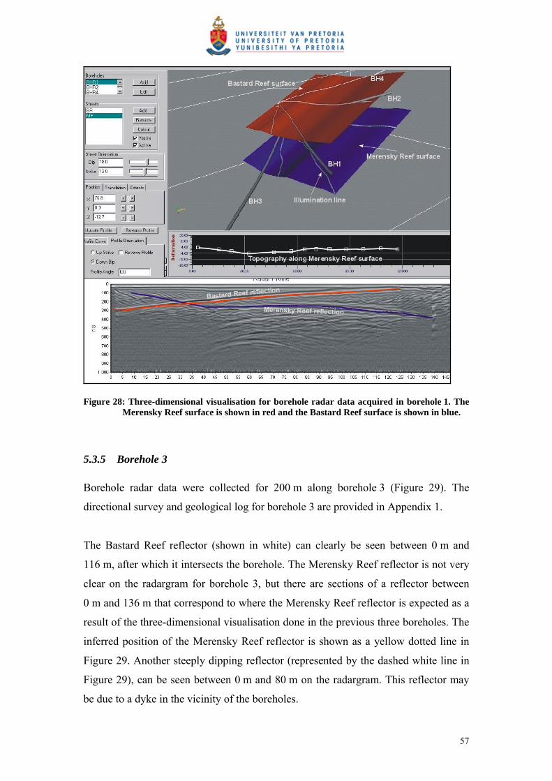
Figure 28: Three-dimensional visualisation for borehole radar data acquired in borehole 1. The Merensky Reef surface is shown in red and the Bastard Reef surface is shown in blue.
5.3.5 Borehole 3
Borehole radar data were collected for 200 m along borehole 3 (Figure 29). The
directional survey and geological log for borehole 3 are provided in Appendix 1.
The Bastard Reef reflector (shown in white) can clearly be seen between 0 m and
116 m, after which it intersects the borehole. The Merensky Reef reflector is not very
clear on the radargram for borehole 3, but there are sections of a reflector between
0 m and 136 m that correspond to where the Merensky Reef reflector is expected as a
result of the three-dimensional visualisation done in the previous three boreholes. The
inferred position of the Merensky Reef reflector is shown as a yellow dotted line in
Figure 29. Another steeply dipping reflector (represented by the dashed white line in
Figure 29), can be seen between 0 m and 80 m on the radargram. This reflector may
be due to a dyke in the vicinity of the boreholes.
57
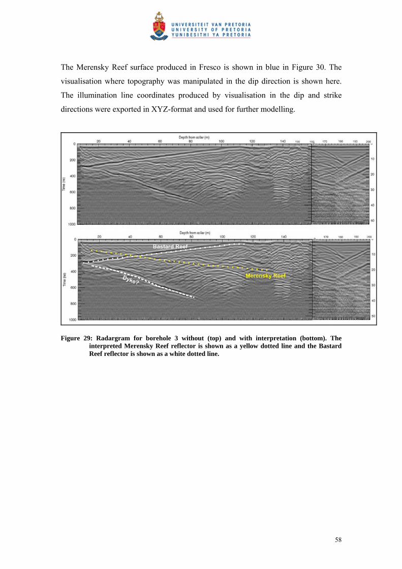
The Merensky Reef surface produced in Fresco is shown in blue in Figure 30. The
visualisation where topography was manipulated in the dip direction is shown here.
The illumination line coordinates produced by visualisation in the dip and strike
directions were exported in XYZ-format and used for further modelling.
Figure 29: Radargram for borehole 3 without (top) and with interpretation (bottom). The interpreted Merensky Reef reflector is shown as a yellow dotted line and the Bastard Reef reflector is shown as a white dotted line.
58
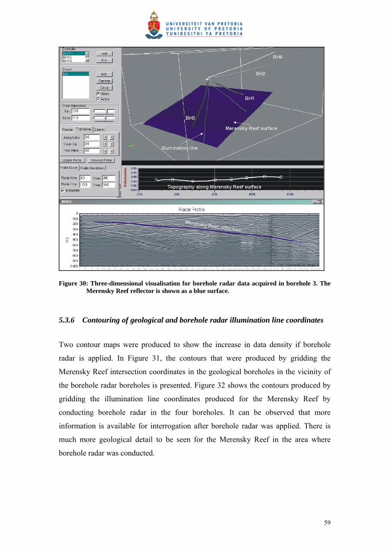
Figure 30: Three-dimensional visualisation for borehole radar data acquired in borehole 3. The Merensky Reef reflector is shown as a blue surface.
5.3.6 Contouring of geological and borehole radar illumination line coordinates
Two contour maps were produced to show the increase in data density if borehole
radar is applied. In Figure 31, the contours that were produced by gridding the
Merensky Reef intersection coordinates in the geological boreholes in the vicinity of
the borehole radar boreholes is presented. Figure 32 shows the contours produced by
gridding the illumination line coordinates produced for the Merensky Reef by
conducting borehole radar in the four boreholes. It can be observed that more
information is available for interrogation after borehole radar was applied. There is
much more geological detail to be seen for the Merensky Reef in the area where
borehole radar was conducted.
59

Figure 31: Contour map produced by gridding the Merensky Reef elevation as logged from geological boreholes in the vicinity of the borehole radar survey
60

Figure 32: Contour map produced by gridding the illumination line coordinates produced by conducting borehole radar in boreholes 1 to 4
61

5.3.7 Three-dimensional surface (all boreholes)
The illumination lines produced by all the three-dimensional visualisations done for
boreholes 1 to 4 were used, together with some Merensky Reef intersections from
geological boreholes in the borehole radar block, to produce a three-dimensional
surface. All the illumination line coordinates used for this study are presented in
Appendix B.
In Figure 33A, the surface constructed by using only the Merensky Reef intersection
from geological boreholes is shown in grey (Surface A). The positions of the
geological boreholes are indicated as red dots.
The surface produced by gridding the XYZ-coordinates of all the illumination lines is
shown in blue (Surface B). In Figure 33A, it can be observed that Surface B slumps
below Surface A, indicating that the borehole radar results show that there is a pothole
structure in the west of the mining block that would not have been detected if only the
reef intersections from the geological boreholes had been used. Only the portion of
the slumped Surface B that differs significantly (more that 1 m) is defined as the
pothole in Figure 34.
This pothole (annotated in Figure 34) has an elliptical shape that is approximately
50 m across and slumps approximately 5 m, which would have significant
implications for the mining of this block. The financial implication of mining into this
pothole is discussed in the cost-benefit analysis conducted in Section 6.
Furthermore, the upward slope of the illumination line for borehole 4 indicates that
the reef may be rolling upwards in the north of the block defined by borehole radar.
This information may also be useful when this block is eventually mined, both
financially and from a safety point of view.
62

A
B
Figure 33: Three-dimensional surfaces constructed for the reef block imaged by borehole radar: A) the grey surface constructed from geological borehole information only, and B) the blue surface constructed by using the borehole radar illumination lines
63
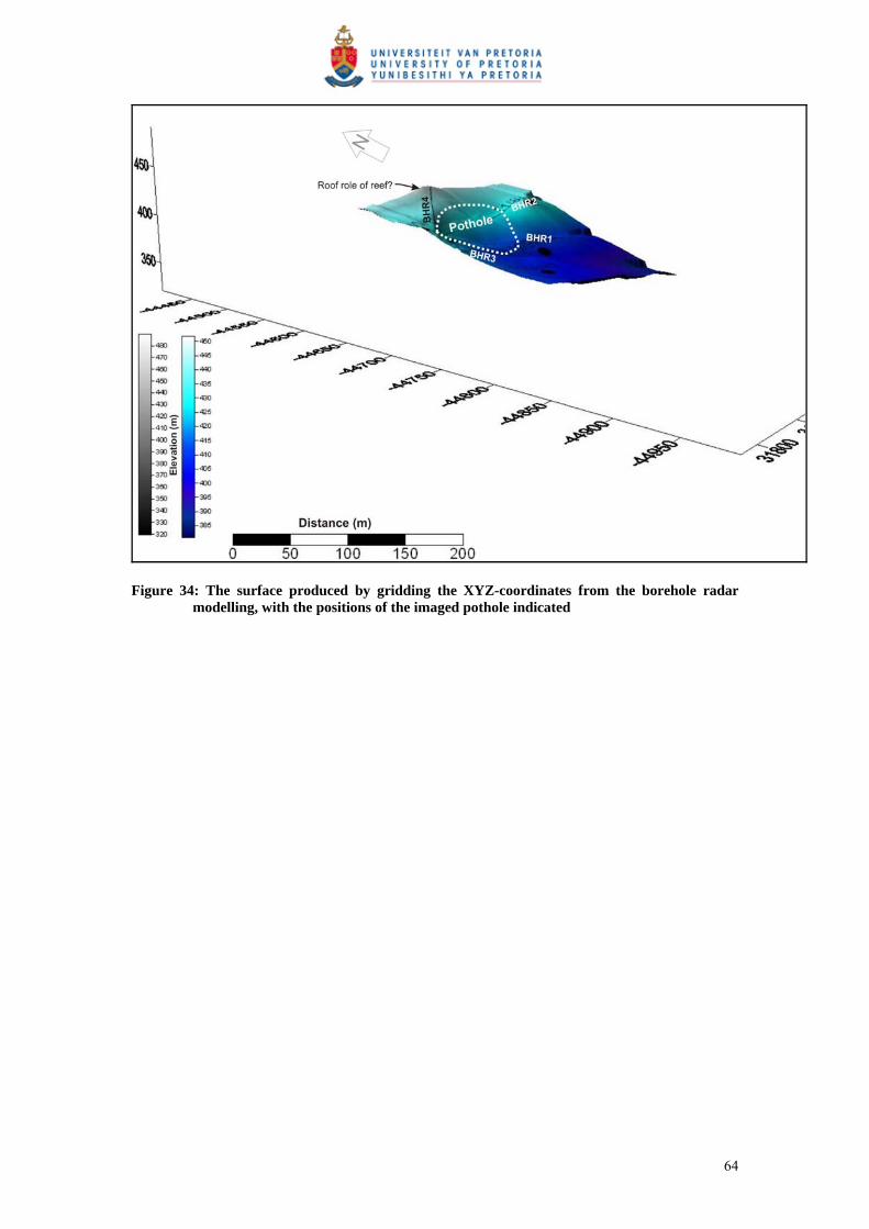
Figure 34: The surface produced by gridding the XYZ-coordinates from the borehole radar modelling, with the positions of the imaged pothole indicated
64
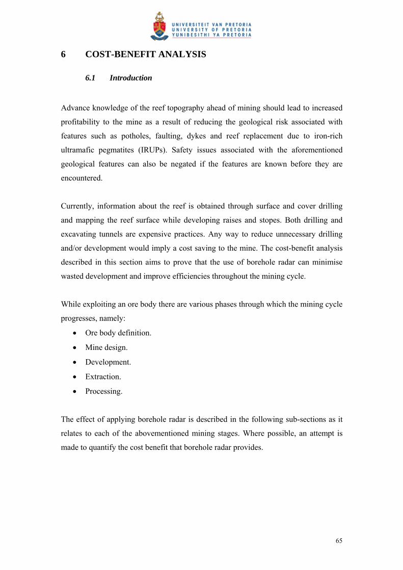
6 COST-BENEFIT ANALYSIS
6.1 Introduction
Advance knowledge of the reef topography ahead of mining should lead to increased
profitability to the mine as a result of reducing the geological risk associated with
features such as potholes, faulting, dykes and reef replacement due to iron-rich
ultramafic pegmatites (IRUPs). Safety issues associated with the aforementioned
geological features can also be negated if the features are known before they are
encountered.
Currently, information about the reef is obtained through surface and cover drilling
and mapping the reef surface while developing raises and stopes. Both drilling and
excavating tunnels are expensive practices. Any way to reduce unnecessary drilling
and/or development would imply a cost saving to the mine. The cost-benefit analysis
described in this section aims to prove that the use of borehole radar can minimise
wasted development and improve efficiencies throughout the mining cycle.
While exploiting an ore body there are various phases through which the mining cycle
progresses, namely:
Ore body definition.
Mine design.
Development.
Extraction.
Processing.
The effect of applying borehole radar is described in the following sub-sections as it
relates to each of the abovementioned mining stages. Where possible, an attempt is
made to quantify the cost benefit that borehole radar provides.
65

6.2 Assumptions
6.2.1 Definition of borehole radar coverage and delineation
The aerial coverage provided by the borehole radar surveys, through the extrapolation
of the illumination lines produced by the borehole radar surveys, is shown in Figure
35A. The area covered by borehole radar is calculated to be: 15,231 m².
In Figure 35B, the area covered by the pothole delineated by the borehole radar
surveys is schematically illustrated. The area of the pothole was defined in the
software package Surfer and measured to be 3,927 m².
A B
Figure 35: Schematic representation of A) the area covered by borehole radar, and B) the area covered by the pothole defined by borehole radar
66
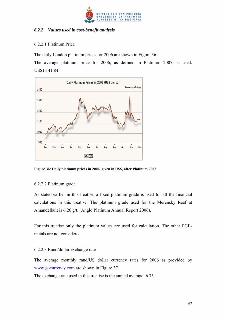
6.2.2 Values used in cost-benefit analysis
6.2.2.1 Platinum Price The daily London platinum prices for 2006 are shown in Figure 36.
The average platinum price for 2006, as defined in Platinum 2007, is used:
US$1,141.84
Figure 36: Daily platinum prices in 2006, given in US$, after Platinum 2007
6.2.2.2 Platinum grade As stated earlier in this treatise, a fixed platinum grade is used for all the financial
calculations in this treatise. The platinum grade used for the Merensky Reef at
Amandelbult is 6.26 g/t. (Anglo Platinum Annual Report 2006).
For this treatise only the platinum values are used for calculation. The other PGE-
metals are not considered.
6.2.2.3 Rand/dollar exchange rate The average monthly rand/US dollar currency rates for 2006 as provided by
www.gocurrency.com are shown in Figure 37.
The exchange rate used in this treatise is the annual average: 6.73.
67

Figure 37: Average 2006 rand/US dollar exchange rate (www.gocurrency.com)
6.2.2.4 Reef thickness A constant reef thickness of 1 m is used for all the financial calculations in this
treatise.
6.2.2.5 Density A density value of 3.4 t/m³ is used in this treatise.
6.3 Ore body definition
The relationship between mineral resources and mineral reserves as outlined in the
SAMREC code (2000) is shown in Figure 38. As confidence in the geoscientific
knowledge increases, mineral resources are upgraded from “inferred” to “indicated”
and finally to “measured”. When further modifying factors relating to the mining,
metallurgical processing, economic characteristics, marketing potential, legal
implications, environmental impact and governmental factors concerning the ore body
are taken into consideration, mineral resources become mineral reserves, which can
either be “probable” or “proved”.
Borehole radar is a geoscientific method that can be used to increase the level of
geoscientific knowledge and therefore improve the confidence in the geological
68
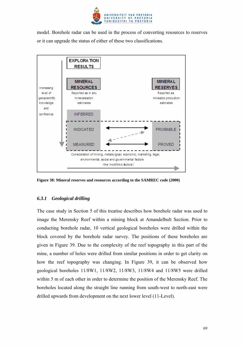
model. Borehole radar can be used in the process of converting resources to reserves
or it can upgrade the status of either of these two classifications.
Figure 38: Mineral reserves and resources according to the SAMREC code (2000)
6.3.1 Geological drilling
The case study in Section 5 of this treatise describes how borehole radar was used to
image the Merensky Reef within a mining block at Amandelbult Section. Prior to
conducting borehole radar, 10 vertical geological boreholes were drilled within the
block covered by the borehole radar survey. The positions of these boreholes are
given in Figure 39. Due to the complexity of the reef topography in this part of the
mine, a number of holes were drilled from similar positions in order to get clarity on
how the reef topography was changing. In Figure 39, it can be observed how
geological boreholes 11/8W1, 11/8W2, 11/8W3, 11/8W4 and 11/8W5 were drilled
within 5 m of each other in order to determine the position of the Merensky Reef. The
boreholes located along the straight line running from south-west to north-east were
drilled upwards from development on the next lower level (11-Level).
69

As seen in Table 3, the total amount of geological drilling, prior to borehole radar, up
to the bottom Merensky Reef contact adds up to 457 m. At an average cost of
R300/m, the total cost of drilling geological boreholes to determine the position of the
bottom Merensky Reef contact was R137,000.
In this study, the cost to assay the geological borehole core is not considered. This
study focuses on defining the position of the Merensky Reef with the defined block,
and not the grade.
Figure 39: A map showing the area covered by the four borehole radar boreholes, indicating the positions of geological boreholes drilled prior to the borehole radar survey
70

Table 3: Geological boreholes in the area covered by the borehole radar surveys. The distance from the borehole collar to the bottom Merensky Reef contact is shown in the last column.
Effectively, due to boreholes being drilled from similar positions, only three
geological borehole positions along a straight line (approximately 132 m in length)
were drilled to intersect the bottom contact of the Merensky Reef. From these
boreholes an estimate of the Merensky Reef position could be made at three points
along this line.
6.3.2 Borehole radar along a single line
If one borehole was drilled parallel to the Merensky Reef contact along this 132 m-
long line, the cost of a borehole radar survey in that hole would be:
Drilling of hole (R300/m): R39,600
Directional survey: R3,000
Borehole radar survey: R44,000
Total: R86,600.
The borehole radar survey will give a continuous line of Merensky Reef coordinates
below this theoretical borehole.
6.3.3 Geological intersect drilling vs. borehole radar
Cost of drilling geological boreholes: R137,000
Cost of one borehole radar survey in hypothetical borehole: R86,600
71

For 1.6 times less the cost of drilling clusters of geological boreholes at three points
along an imaginary line, a borehole radar survey conducted from a borehole along this
theoretical line will yield continuous reef elevation positions all along the line as
opposed to reef intersections at three points. It is clear that the level of geological
confidence acquired from reef elevation coordinates along a continuous line is much
higher than only having the reef intersection at three points. Conducting borehole
radar in a 132 m borehole will yield at the very least 44 illumination line coordinates,
if the sampling interval of the trajectory survey is 3 m. In Table 4, the cost per reef
elevation point is compared when geological drilling is conducted vs. applying
borehole radar. It can be seen that the cost per point is 23 times smaller when using
borehole radar to determine the reef elevation.
Table 4: Cost per reef elevation point for geological drilling, compared with conducting a borehole radar survey
Points defined Cost Cost/point
Geological drilling 3 R137,000 R45,667
Borehole radar 44 R86,600 R1,968
This comparison did not take into account that the up-holes drilled from the lower
level could not pinpoint the position of the reef.
As the geological confidence is increased, the mineral resource can be converted from
“inferred” to “indicated”, which is associated with a reduction in risk when mining the
ore body.
6.3.4 Borehole radar over the entire block
Four borehole radar surveys were conducted to define the mining block. The total
lengths of borehole radar data collected are given in Table 5.
72
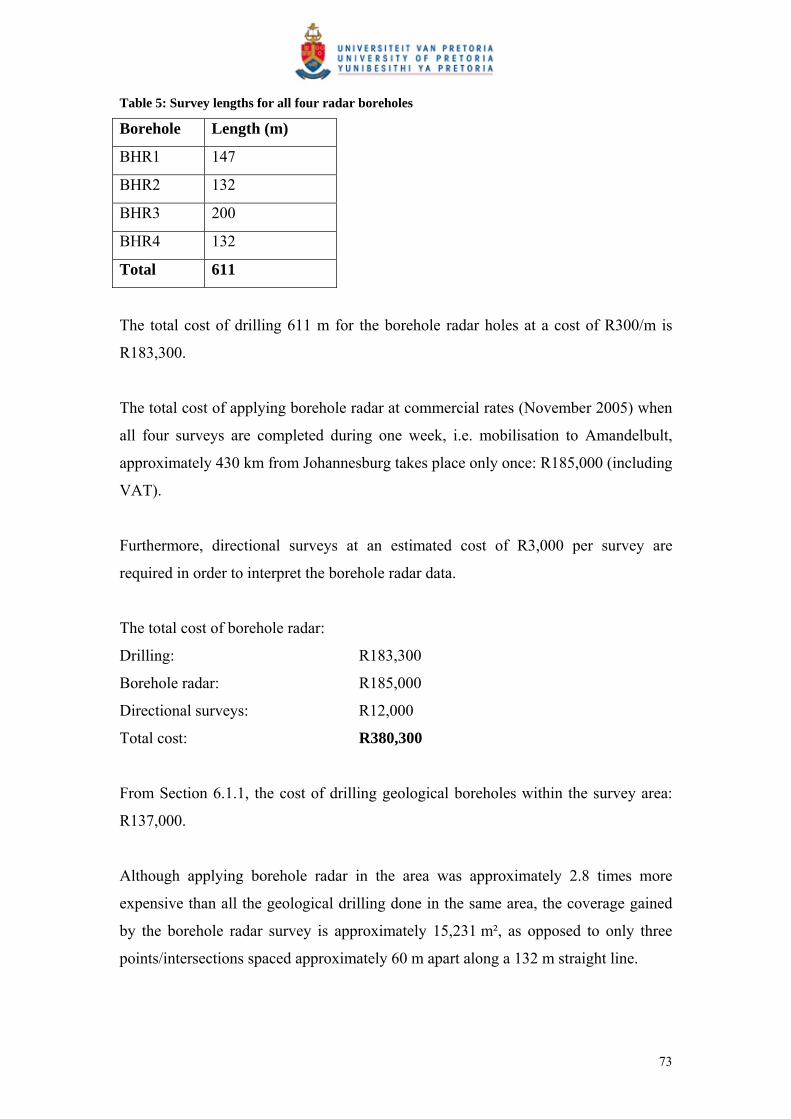
Table 5: Survey lengths for all four radar boreholes
Borehole Length (m)
BHR1 147
BHR2 132
BHR3 200
BHR4 132
Total 611
The total cost of drilling 611 m for the borehole radar holes at a cost of R300/m is
R183,300.
The total cost of applying borehole radar at commercial rates (November 2005) when
all four surveys are completed during one week, i.e. mobilisation to Amandelbult,
approximately 430 km from Johannesburg takes place only once: R185,000 (including
VAT).
Furthermore, directional surveys at an estimated cost of R3,000 per survey are
required in order to interpret the borehole radar data.
The total cost of borehole radar:
Drilling: R183,300
Borehole radar: R185,000
Directional surveys: R12,000
Total cost: R380,300
From Section 6.1.1, the cost of drilling geological boreholes within the survey area:
R137,000.
Although applying borehole radar in the area was approximately 2.8 times more
expensive than all the geological drilling done in the same area, the coverage gained
by the borehole radar survey is approximately 15,231 m², as opposed to only three
points/intersections spaced approximately 60 m apart along a 132 m straight line.
73

If the area imaged from the four borehole radar holes represents the area of Merensky
Reef for that block, the value of that reef section can be calculated as follows:
Area of Merensky Reef 15,231 m² Defined in Section 6.2.1 Average thickness of reef 1 m Volume of reef 15,231 m³ SG 3.4 t/m³ Tonnes of reef 51,785.4 t
Average grade/tonne (Pt) 6.26 g/t Anglo Platinum Annual Report (2006)
Grams of Pt in situ 324,176.604 g Grams in a troy ounce 31.1 Ounces of Pt in situ 10,423.68502 $ Average Pt price (2006) 1,141.84 $ Platinum 2007 Value of Pt in situ 11,902,180.5 $ Average R/$ exchange (2006) 6.73 www.gocurrency.com Rand value of Pt in situ 80,101,674.76 R
If we take the rand value of the platinum in the Merensky Reef (R80,101,674.76) and
compare it with the price of applying borehole radar for that mining block
(R380,300), we can see that for 0.47% of the value of the in situ reef, the geological
confidence in the mining block can be significantly increased.
Expressed differently: if the cost of borehole radar is calculated per tonne of
Merensky Reef, it can be shown that to delineate 51,785 t of reef with borehole radar
will cost R380,300, i.e. R7.34 per tonne. Compared with an average production cost
of R380/t (De Jager, pers comm) for producing one tonne of platinum at Amandelbult
Section, borehole radar makes out 1.9% of the total production cost.
The cost of applying borehole radar in relation to the in situ value of the platinum as
well as in relation to the total production cost for the defined area is represented with
pie charts in Figure 40.
74
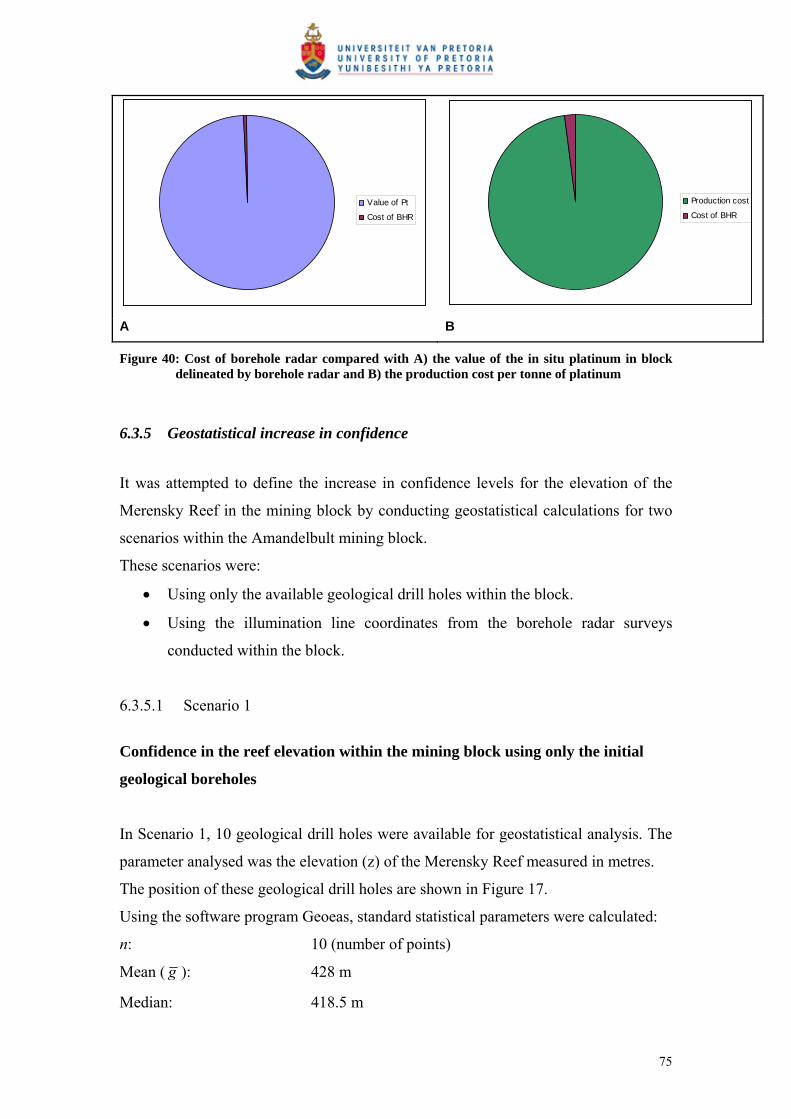
Value of Pt
Cost of BHR
Production cost
Cost of BHR
A B
Figure 40: Cost of borehole radar compared with A) the value of the in situ platinum in block delineated by borehole radar and B) the production cost per tonne of platinum
6.3.5 Geostatistical increase in confidence
It was attempted to define the increase in confidence levels for the elevation of the
Merensky Reef in the mining block by conducting geostatistical calculations for two
scenarios within the Amandelbult mining block.
These scenarios were:
Using only the available geological drill holes within the block.
Using the illumination line coordinates from the borehole radar surveys
conducted within the block.
6.3.5.1 Scenario 1
Confidence in the reef elevation within the mining block using only the initial
geological boreholes
In Scenario 1, 10 geological drill holes were available for geostatistical analysis. The
parameter analysed was the elevation (z) of the Merensky Reef measured in metres.
The position of these geological drill holes are shown in Figure 17.
Using the software program Geoeas, standard statistical parameters were calculated:
n: 10 (number of points)
Mean ( g ): 428 m
Median: 418.5 m
75

Standard deviation (s): 23.56 m
Since the mean and median were similar, a normal distribution was assumed for
further calculations. Since there were fewer than 10 data points, the following
equation was used to calculate confidence levels:
n
sg
n
s833.1833.1 (2) (Clarke, 2000)
In this treatise, the 90% confidence level is used for consistency.
Using equation (2), it can be deducted that the analyst can be 90% sure that the mean
of this dataset is between 414 m and 442 m. The confidence range is 28 m.
This means that the elevation of the Merensky Reef within the area defined by the
borehole radar boreholes can be estimated with an error of up to 28 m, if only the
elevation information from the 10 geological boreholes is used.
6.3.5.2 Scenario 2
Confidence in the reef elevation using the borehole radar illumination line
coordinates
In Scenario 2, all the illumination line coordinates produced for radar boreholes 1 to 4
were used for geostatistical analysis. The modelling both in the dip and strike
direction was considered. A total of 716 elevation points were generated in the mining
block using illumination line forward modelling.
Using the software program Geoeas, various statistical parameters were calculated:
n: 716 (number of points)
Mean ( g ): 416 m
Median: 415 m
Standard deviation (σ): 16.33 m
It stands to reason that the increase in data points will improve the level of confidence
at which the mean can be calculated.
Since there were more than 25 data points, the following equation was used to
determine the confidence levels:
ng
n
645.1645.1 (3) (Clarke, 2000)
76
Using equation (3), it follows that the analyst can be 90% sure that the mean of this
dataset is between 415 m and 417 m, i.e. the confidence range is 2 m.
This means that the elevation of the Merensky Reef can be estimated at a much higher
accuracy than using only the geological drilling within the mining block. The
confidence range has improved from 28 m to 2 m, a 14-fold improvement.
Therefore, if borehole radar is used to delineate a mining block, the reef elevation can
be determined with much more confidence than relying on geological borehole
intersections alone.
6.3.5.3 Discussion
Using basic geostatistical equations, it can be concluded that the application of
borehole radar in the mining block has significantly improved the level of confidence
in the position of the Merensky Reef.
Stated differently, to achieve the same level of confidence as provided by borehole
radar, 716 vertical geological boreholes would have been required.
The average length of the geological boreholes used in the mining block to intersect
the Merensky Reef was 46 m (using values in Table 3). If 716 of these boreholes were
drilled at a drilling cost of R300/m, the total cost would be 716 x 46 x 300m =
R9,880,800.
The same level of confidence was achieved with four borehole radar surveys at a cost
of R380,300, i.e. 3.84% of the cost of drilling 716 geological boreholes.
6.4 Mine design
Mine design and mine development are very closely related. In this section it is shown
that the area that is to be developed is sampled better if borehole radar is applied prior
to development as opposed to only using geological boreholes to fix the position of
77

the reef. If the position of the ore body ahead of mining can be determined accurately,
the mine design can be fixed and mining can continue unhindered, without any
surprises.
6.4.1 Area of Merensky Reef sampled with standard geological drilling
At Amandelbult Section, it is currently normal practice to drill three vertical boreholes
per planned cross-cut spacing, i.e. approximately three boreholes per 200 m of
haulage development (Figure 41).
Figure 41: Borehole radar survey layout indicating vertical boreholes meant to “cover” mining block between 9W and 8W crosscut on 10-Level
Approximately 100 m of reef intersection (vertical) drilling is completed in one month
to cover the position of cross-cuts and raises. If a drilling cost of R300/m is used, this
equates to R30,000 of drilling per month to ensure that development is placed
optimally to extract the ore body, and this is assuming that the geology is not
complex, i.e. no additional drilling is required to pinpoint the position of the reef.
78
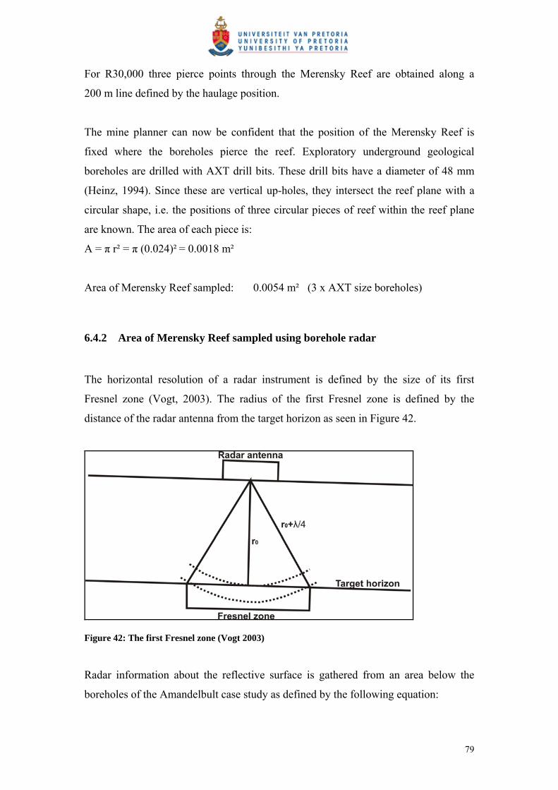
For R30,000 three pierce points through the Merensky Reef are obtained along a
200 m line defined by the haulage position.
The mine planner can now be confident that the position of the Merensky Reef is
fixed where the boreholes pierce the reef. Exploratory underground geological
boreholes are drilled with AXT drill bits. These drill bits have a diameter of 48 mm
(Heinz, 1994). Since these are vertical up-holes, they intersect the reef plane with a
circular shape, i.e. the positions of three circular pieces of reef within the reef plane
are known. The area of each piece is:
A = π r² = π (0.024)² = 0.0018 m²
Area of Merensky Reef sampled: 0.0054 m² (3 x AXT size boreholes)
6.4.2 Area of Merensky Reef sampled using borehole radar
The horizontal resolution of a radar instrument is defined by the size of its first
Fresnel zone (Vogt, 2003). The radius of the first Fresnel zone is defined by the
distance of the radar antenna from the target horizon as seen in Figure 42.
Figure 42: The first Fresnel zone (Vogt 2003)
Radar information about the reflective surface is gathered from an area below the
boreholes of the Amandelbult case study as defined by the following equation:
79
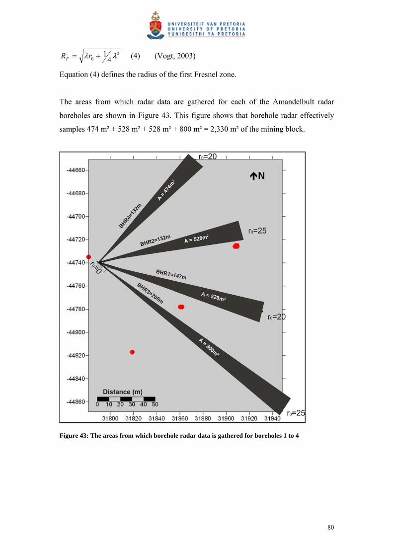
20 4
1 rRF (4) (Vogt, 2003)
Equation (4) defines the radius of the first Fresnel zone.
The areas from which radar data are gathered for each of the Amandelbult radar
boreholes are shown in Figure 43. This figure shows that borehole radar effectively
samples 474 m² + 528 m² + 528 m² + 800 m² = 2,330 m² of the mining block.
Figure 43: The areas from which borehole radar data is gathered for boreholes 1 to 4
80

6.4.3 Discussion
When standard geological drilling is done at regular intervals down the haulage to get
an idea of the block that is to be mined into, the position of the Merensky Reef is
known over an area of 0.0054 m² at a cost of R30,000, i.e. R5,600,000 per m².
Using standard geological drilling, 0.00035% of the 15,231 m² mining block is
sampled.
When borehole radar is applied from four boreholes drilled sub-parallel to the target
surface, an area of 2,330 m² is sampled at a cost of R380,300, i.e. R163 per m².
Using borehole radar, 15.3% of the 15,231 m² mining block is sampled.
Borehole radar increases the sampling area 431,481 times over standard geological
drilling at a significantly reduced cost (Figure 44). It is clear that the application of
borehole radar prior to mining significantly increases the knowledge about the ore
body prior to mining. A much larger area of the area to be mined is sampled and if the
cost of this sampling is compared with standard geological drilling conducted to
“cover” the position of the Merensky Reef within the mining block, it can be seen that
borehole radar is also significantly cheaper.
Figure 44: Increase in sampling area if borehole radar is conducted
81

6.5 Development
The conventional mining layout is used at Amandelbult Section (shown in Figure 15).
Development takes place in three ways:
1. Secondary development
Footwall haulages, developed on strike at a constant distance below the reef
plane.
Cross-cuts, developed horizontally to intersect the reef plane.
2. Primary development
Raises developed in the reef plane.
3. Ancillary development
Other development such as travelling ways, ore passes, timber pays, drilling
cubbies et cetera.
In Section 4.3.2 (Figure 16), the conventional mining progression within a mining
block is described. From opposite raise lines, mining proceeds in panels until a natural
dip pillar is left for support in the centre of the block.
Once the raises have been developed, the reef between two neighbouring raises is
extracted or stoped. Mine development is expressed as a ratio called the m²/m ratio,
where:
The m² refers to the area of reef that is available for mining after the necessary
development is done, and the m refers to the development required to provide access
to the reef.
The m²/m ratio is affected by various factors, such as the geometry of the reef, the dip
and structural complexity of the reef as well as the mining efficiencies achieved when
extracting the reef. According to De Jager (pers comm), the m²/m ratio should
theoretically be in the vicinity of 50 m²/m, but due to the factors listed above, typical
values range between of 20 m²/m and 25 m²/m.
The m²/m ratio for the mining block imaged by borehole radar is calculated below.
82
Let’s assume the area of reef available for mining is 15,231 m², i.e. we take the same
amount of reef available for mining as imaged by borehole radar described in Section
6.2.1 (Figure 35).
If the m²/m ratio is taken as 25, then 609 m of development was required to make this
reef available.
This case study described in Section 3 shows that borehole radar imaged a pothole in
the Merensky Reef. This pothole is an elliptical feature with a long axis of
approximately 100 m, a short axis of approximately 50 m and a slump of
approximately 5 m. Due to the size of the slump, this elliptical area defined by the
pothole is not available for mining. The area of the pothole was calculated in the
mapping software as 3,927 m².
The total area available for mining is now 15,231 m² – 3,927 m² = 11,304 m².
If the presence of the pothole was unknown (i.e. borehole radar had not been applied),
then the same amount of development would have taken place, i.e. 609 m.
The m²/m ratio would then have been 11,304/609 = 18.56 m²/m, i.e. with the same
amount of development, 6.4 m² less would have been available for mining.
Converted to monetary values:
83

If the development cost is taken at R3,500/m (De Jager, pers comm):
A B
Development cost 609 x R3,500 =R2,131,500 609 x R3500 =R2,131,500
Reef available 15,231 m² 11,304 m²
Reef thickness 1 m² 1 m²
Reef volume 15,231 m³ 11,304 m³
SG 3.4 t/m³ 3.4 t/m³
Tonnes of reef 51,784.4 t 38,433.6 t
Average grade 6.26 g/t 6.26 g/t
Grams of Pt in situ 324,177 g 240,594 g
Ounces of Pt in situ 10,423 oz 7,736 oz
Average platinum price $1141.84/oz $1141.84/oz
$ value of Pt in situ $11,902,181 $8,833,448
R/$ exchange (Apr 2006) 6.73 6.73
R value of Pt in situ R80,101,675 R59,449,106
In Case A, R2,688,000 was spent on development for in situ ore worth R80,101,675,
while in Case B the same amount was spent on development for in situ ore worth
R20,652,569 less.
As described above, 609 m of development is required to make a potential 15,231 m²
of reef available for mining. The percentage of reef affected by pothole A is 25.78%.
Development cost per metre: R3,500
Development metres at risk due to 25.78% geological loss: 157.02 m
Cost of development at risk: R549,563
This result relates back to the scenario described in Section 6.4, which relates to mine
planning. If the position of the pothole had been known the design of the mine could
have been adapted in order to minimise the amount of ore lost due to the pothole.
According to Van Wyk (pers comm), the position of development can be adapted if
the positions of disruptions to the reef plane are known. According to Van Wyk (pers
comm), cross-cuts can be positioned up to 1 km apart if necessary.
84

6.6 Extraction
6.6.1 Deferred income
As described in Section 4.3.2, a pothole is considered a problem to mining if it fills up
more than one-third of a mining panel. The pothole delineated by borehole radar on
10-Level 9W cross-cut, as described in Section 5.3.7, would have posed a problem to
mining, since its side view at this section is approximately 100 m long. If it was
mined until one-third of a panel was exposed (i.e. 12 m of the face), the following
calculations can be done:
For 1 m advance at a face length of 12 m (i.e. per blast):
Area of Merensky Reef displaced 12 m² Average thickness of reef 1 m Volume of reef 12 m³ SG 3.4 t/m³ Tonnes of reef 40.8 t
Average grade/tonne (Pt) 6.26 g/t Anglo Platinum Annual Report (2006)
Grams of Pt in situ 255.408 g Grams in a troy ounce 31.1 Ounces of Pt in situ 8.21 $ Average Pt price (2006) 1,141.84 $ Platinum 2007 Value of Pt in situ 9377 $ Average R/$ exchange (2006) 6.73 www.gocurrency.com Rand value of Pt in situ 63,109 R
This means that for each blast that is mined into the pothole, R63,109 of income is
deferred until a later date.
6.6.2 Labour efficiency
The ore body is extracted by stoping. Stoping is carried out by mining crews. For this
exercise it is assumed that there are 14 people in a mining crew.
Average cost to company per month per mining-crew employee: R8,000
Total monthly cost to company for 14-person mining crew: R112,000
85

Let’s assume this mining crew is advancing along a panel that is 35 m wide as shown
in Figure 45.
Figure 45: Hypothetical monthly advance of a mining crew along a 35 m long panel
For three cases A, B and C, the situation is as follows:
Per month: A B C
Advance 12 m 14 m 16 m
Area 420 m² 490 m² 560 m²
Employee cost R112,000 R112,000 R112,000
Employee cost/m² R267/m² R229/m² R200/m²
The calculation above shows that the saving in labour due to efficiency for advancing
14 m instead of 12 m is: R267 – R229 = R38/m².
If this cost is applied to the mining block covered by borehole radar that has a surface
area of 15,231 m², the saving is 15,231 m² x R38 = R578,778.
Predicted in situ value of ore in mining block: R80,101,674.76
Although the example given here is hypothetical, it serves to demonstrate that if
disruptions in the ore body can be predicted using borehole radar and stope advance
can be increased by as little as 2 m the mine can save 0.7% of the value of the in situ
ore.
86
The result is that mining crews can be used more efficiently, and unnecessary
development into waste rock can be prevented.
6.7 Processing
The processing of the ore extracted is directly affected by the presence of waste
material. The ore is effectively diluted and waste material that displaces ore in the mill
will lead to inefficiencies and a loss of revenue.
In this example it is assumed that the pothole material is mined through and reports to
ore in the plant, i.e. it is not detected as waste material. According to Marais (pers
comm), this scenario will most likely be prevented by daily monitoring of the plant
head-grade, but another reason why this calculation is of importance is that if the
pothole is mined through in the hope that reef will be encountered, the result is
“deferred income”, i.e. waste is being mined as ore and income that would have been
derived from ore is being postponed until a later date.
Tonnes covered by mining block described in Section 6.5: 51,784 t
Tonnes of waste due to pothole A: 13,350 t
Cost per tonne (shaft head + overheads + concentrator): R380
Mining cost of waste tonnes mined as ore: R5,073,000
The loss of revenue due to mining through the pothole can be calculated as follows:
Tonnes milled from mining block described in Section 6.5: 51,784 t
Planned contained Pt at 6.26g/t: 10,423 ounces
Actual contained Pt (diluted 25.78%): 7,736 ounces
Lost Pt: 2,687 ounces
Lost revenue at $1,141.84/oz and exchange rate of 6.73: R20,648,475
If the loss of revenue for one mining block is R20,648,475, the impact on the entire
mine where waste is mined instead of ore due to unpredicted geological losses will be
significant.
87
7 CONCLUSIONS AND RECOMMENDATIONS
7.1 Conclusions
This project aimed to provide clear evidence that incorporating borehole radar in the
mining cycle will provide significant cost benefit in the long term.
This study has shown that the application of borehole radar prior to mining:
Provides more geological information about the reef prior to mining than relying
only on geological intersection of the reef.
Can provide continuous reef coordinates along the illumination line, as opposed
to the point intersections provided by geological cover drilling.
Significantly improves the confidence in the elevation of the Merensky Reef
within the mining block.
Samples a much larger portion of the reef to be extracted than standard geological
drilling at a significantly reduced cost.
Improves mine planning and ensures that mine development is put in the correct
place.
Avoids unnecessary mine development.
Can ensure that mining teams are deployed more effectively in areas where reef
has been defined by borehole radar.
Can prevent sending waste to the plant instead of ore.
Can avoid deferring income until a later date.
The findings that were calculated in the previous sections are summarised in Table 6.
Results are given for the scenario where only geological drilling would have been
used to make mining decisions about the defined mining block, as opposed to the
situation after borehole radar was applied. The broad impact of borehole radar at the
various mining cycles is shown in Table 7.
88

Table 6: Conclusions summarised for applying only geological drilling, compared with conducting borehole radar
Geological drilling
(before borehole radar
was applied)
Borehole radar
Number of reef elevation
coordinates
4 716
Cost per reef elevation point R45,667 R1,968
Extrapolated area covered 4 intersection points
within block
15,231 m²
Confidence range (of
geostatistical mean)
28 m 2 m
Actual area of reef sampled 0.0054 m² 2,330 m²
% of mining block sampled 0.00035% 15.3%
Cost per m² sampled R5,600,000 R163
m²/m ratio 18.56 25
Expected value of in situ
platinum
R80,101,675 R59,449,106
Cost of development at risk R549,563 R0
Income deferred R63,109 per 12 x 1 m
advance
R0
Reduction in labour cost per
block
R0 R578,778
Cost of processing waste as
ore (or deferred income)
R20,648,475 R0
89
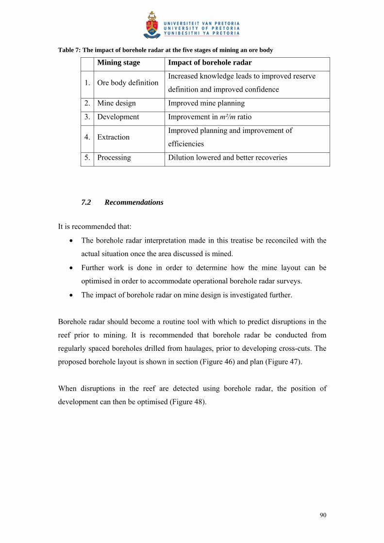
Table 7: The impact of borehole radar at the five stages of mining an ore body
Mining stage Impact of borehole radar
1. Ore body definition Increased knowledge leads to improved reserve
definition and improved confidence
2. Mine design Improved mine planning
3. Development Improvement in m²/m ratio
4. Extraction Improved planning and improvement of
efficiencies
5. Processing Dilution lowered and better recoveries
7.2 Recommendations
It is recommended that:
The borehole radar interpretation made in this treatise be reconciled with the
actual situation once the area discussed is mined.
Further work is done in order to determine how the mine layout can be
optimised in order to accommodate operational borehole radar surveys.
The impact of borehole radar on mine design is investigated further.
Borehole radar should become a routine tool with which to predict disruptions in the
reef prior to mining. It is recommended that borehole radar be conducted from
regularly spaced boreholes drilled from haulages, prior to developing cross-cuts. The
proposed borehole layout is shown in section (Figure 46) and plan (Figure 47).
When disruptions in the reef are detected using borehole radar, the position of
development can then be optimised (Figure 48).
90

Figure 46: Proposed borehole layout in section for applying borehole radar to detect geological deviations prior to mining
Figure 47: Proposed borehole radar layout in plan for the prediction of geological disruptions prior to mine development
91

Figure 48: Optimisation of mine development after the application of borehole radar
92

8 ACKNOWLEDGEMENTS
The Platmine Research Collaborative is thanked for allowing this work to be
published.
Declan Vogt at the CSIR, is thanked for many useful discussions and being my
borehole radar guru.
Bruce Walters, Quartus Snyman and Wian Marais at Anglo Platinum are thanked for
their efforts in securing the case-study site at Amandelbult Section as well as for their
inputs in useful discussion relating to the results produced here.
Alan King from Anglo Technical Division is thanked for his valuable input to
financial discussions and for motivating me to go the extra mile.
Andy Rompel Stompel is thanked for checking that a geophysicist is getting the
geology right.
Carel de Jager from Anglo Platinum is thanked for providing the basis of the financial
analysis.
Ferdi Camisani-Calzolari is thanked for teaching me the basics of geostatistics.
Prof. Hennie Theart is thanked for his inputs and suggestions, and for throwing my
first draft across the room.
My family is thanked for giving me nonsense whenever I procrastinated.
My friend, “Eagle-eye” Riaan Wolmarans, is thanked for wading through a very
technical piece of editing.
My friends are thanked for partying on my behalf while I was chained to my
computer.
93

Last but by no means least, my husband, Albert Swart, is thanked for supporting me
in every crazy project that I tackle.
94

9 REFERENCES
Anglo Platinum. (2006) Annual Report.
Carr, H.W., Groves, D.I. and Cawthorn, R.G. (1994). The importance of synmagmatic
deformation of Merensky Reef potholes in the Bushveld Complex, Economic
Geology, 89, 1398 – 1410.
Cawthorn, R.G. (1999). The platinum and palladium resources of the Bushveld
Complex, South African Journal of Science, 95, 481 – 489.
Chalke, B.L., Chalke, T. and Rompel, A.K.K. (2006) Paardekraal #2 Mine Expansion
Project, PDL 159 Geotechnical Interpretation Report. Internal Anglo Technical
Division Report Number 15/173/141/2006/158, 51pp.
Clarke, I. and Harper, W.V. (2000) Practical Geostatistics 2000, Ecosse North
America Llc, Columbus, Ohio, USA. 342pp.
Daniels, J.D. (2004) Ground Penetrating Radar, 2nd Edition. The Institution of
Electrical Engineers, London.
De Jager, C. (2006) Principal Mining Economist, Mining Economics, Anglo
Technical Division, Personal Communication.
De Vries, P. and Du Pisani, P. (2005) Borehole radar delineation of the UG2 Reef at
Modikwa Mine. 9th SAGA Biennial Technical Meeting and Exhibition.
September 2005. Cape Town.
Du Pisani, P. and Vogt, D. (2003) Radar frequency electrical properties of rocks
associated with the VCR, UG2 and Merensky ore bodies. 8th SAGA Biennial
Technical Meeting and Exhibition. September 2003. Pilanesberg.
95
Du Pisani, P. and Vogt, D. (2004) Borehole radar delineation of the Ventersdorp
Contact Reef in Three Dimensions. Exploration Geophysics. 35, 319 – 323.
Du Plessis, A. and Kleywegt, R.J. (1987) A dipping sheet model for the mafic lobes
of the Bushveld Complex. South African Journal of Geology. 90, 1 – 6.
Eales, H.V., Botha, W.J., Hattingh, P.J., De Klerk, W.J., Maier, W.D. and Odgers,
A.T.R. (1993) The mafic rocks of the Bushveld Complex: a review of
emplacement and crystallization history, and mineralization, in light of recent
data. Journal of African Earth Science. 16, 121 – 142.
Eales, H.V. and Cawthorn, R.G. (1996) The Bushveld Complex. In: Cawthorn, R.G.
(Ed.), Layered Intrusions. Elsevier, Amsterdam, 181 – 230.
Farquar, J. (1986) The Western Platinum Mine. In: Anhaeusser, C.R. and Maske, S.
(Eds.), Mineral Deposits of Southern Africa. Geological Society of South
Africa. Johannesburg, South Africa, II, 1135 – 1142.
Heinz, W.F. (1994) Diamond Drilling Handbook 3rd Edition. W.F. Heinz, Halfway
House.
Irvine, T.N. (1982) Terminology for layered intrusions. Journal of Petrology. 23, 127
– 162.
Kinloch, E.D. and Peyerl, W. (1990) Platinum-group minerals in various rock types of
the Merensky Reef: genetic implications. Economic Geology. 85, 537 – 555.
Kruger, F.J. (1990) The stratigraphy of the Bushveld Complex: a reappraisal and the
relocation of the Main Zone boundaries. South African Journal of Geology. 94,
376 – 381.
Leeb Du Toit, A. (1986). The Impala Platinum Mines. In: Anhaeusser, C. R. and
Maske, S (Eds.), Mineral Deposits of Southern Africa. Geological Society of
South Africa. Johannesburg, South Africa, II, 1091 – 1106.
96

Marais, W. (2007) Senior Geologist, Central Functions, Anglo Platinum Rustenburg
Section. Personal communication.
Noon, D.A., Stickley, G.F., and Longstaff, D. (1998). A frequency independent
characterisation of GPR penetration and resolution performance. Journal of
Applied Geophysics. 40, 127 – 137.
Platinum 2007 (2007). Johnson Matthey, Hertfordshyre, England. 56pp.
SAMREC Code. (2000) South African code for reporting of mineral resources and
mineral reserves (the SAMREC code) – Prepared by the South African mineral
resource committee (SAMREC) under the auspices of the SAIMM. Effective
March 2000, SAIMM, Johannesburg, South Africa, 39pp.
Schürmann, L.W. (1991) The geochemistry and petrology of the upper critical zone of
the Boshoek section of the western Bushveld Complex. Bulletin of the
Geological Survey of South Africa. 113, 88pp.
Simmat, C. M., Osman, N., Hargreaves., Mason, I. M., (2002) Borehole radar imaging
from deviating boreholes: Ninth International Conference on Ground
Penetrating Radar, S.K. Koppenjan, H. Lee, (Eds.), Proceedings of SPIE. 4758,
404 – 409.
Turner, G., Mason, I., Hargreaves J., and Wellington, A. (2000) Borehole radar
surveying for orebody delineation: Eighth International Conference on Ground
Penetrating Radar, D.A. Noon., G.F. Stickley, D. Longstaff, (Eds.),
Proceedings of SPIE. 4084, 282 – 287.
Turner, G. and Siggins, A.F. (1994) Constant Q attenuation of subsurface radar
pulses. Geophysics. 59. 1192 – 1200.
Unknown. (1986) A Guide to the Geology of Amandelbult, based on Anhaeusser and
Maske, 1986.
97

Van Wyk, A. (2006) Production Manager, Amandelbult 1-Shaft. Personal
communication.
Viljoen, M.J. (1994) A review of regional variations in facies and grade distribution
of the Merensky Reef, Western Bushveld Complex, with some mining
implications. Proceedings of the 15th CMMI Congress. South African Institute
of Mining and Metallurgy, 183 – 194.
Viljoen, M.J. (1999) The nature and origin of the Merensky Reef of the Western
Bushveld Complex based on geological facies and geophysical data. South
African Journal of Geology. 102. 221 – 239.
Viljoen, M.J. and Hieber, R.W. (1986) The Rustenburg Section of Rustenburg
Platinum Mines Limited, with reference to the Merensky Reef. In: Anhaeusser,
C.R. and Maske, S. (Eds), Mineral Deposits of Southern Africa. Geological
Society of South Africa Johannesburg, South Africa, II. 1107 – 1134.
Viljoen, M.J. and Schürmann, L.W. (1998) Platinum Group Metals. In: Wilson,
M.G.C. and Annhaeusser, C.R. (Eds.), The Mineral Resources of South Africa.
Council for Geoscience, South Africa, Pretoria, 532 – 568.
Viljoen, M.J., De Klerk, W.J., Coetzer., Hatch, N.P., Kinloch, E.D. and Peyerl, W.
(1986a) The Union Section of Rustenburg Platinum Mines Limited, with
reference to the Merensky Reef. In: Anhaeusser, C.R. and Maske, S. (Eds.),
Mineral Deposits of Southern Africa. Geological Society of South Africa,
Johannesburg, South Africa, II. 1061 – 1190.
Viljoen, M.J., Theron, J., Underwood, B., Walters, B.M., Weaver, J. and Peyerl, W.
(1986b) The Amandelbult Section of Rustenburg Platinum Mines Limited, with
reference to the Merensky Reef. In. Anhaeusser, C.R. and Maske, S. (Eds),
Mineral Deposits of Southern Africa. Geological Society of South Africa
Johannesburg, South Africa, II. 1041 – 1060.
98
Vogt, D. (2000) The modelling and design of Radio Tomography antennas: D.Phil.
Thesis, University of York.
Vogt, D. (2002) A Slimline Borehole Radar for In-Mine Use. 9th International
Conference on Ground Penetrating Radar, Proceedings of SPIE, 5758, 31 – 36.
Vogt, D. (2003) An introduction to Ground Penetrating Radar. Course notes for
geophysicists. Wits University. CSIR Miningtek. Johannesburg.
Vogt, D., Van Schoor, M. and Du Pisani, P. (2005) The application of radar
techniques for in-mine feature mapping in the Bushveld Complex of South
Africa. The Journal of the South African Institute of Mining and Metallurgy.
105. 391 – 399.
Vogt, D. (2006) A borehole radar system for South African gold and platinum mines.
South African Journal of Geology. 109. 521 – 528.
Vogt, D. (2007) Competency Area Manager, Mining, Department of Natural
Resources and the Environment, CSIR, Personal communication.
Wagner, P.A. (1929) The Platinum Deposits and Mines of South Africa. Oliver and
Boyd, Edinburgh, Scotland, 326pp.
www.gocurrency.com, [Web page]: accessed 17 September 2007.
www.platmine.co.za, [Web page]: accessed 9 July 2006.
www.platinummetalsreview.com, [Web page]: accessed 12 July 2007.
99
APPENDIX A BOREHOLE INFORMATION
Rock and stratigraphy codes Code ExplanationBR Bastard ReefCOL CollarDYK DykeEOH End of holeFERPL Iron replacementFRAC FractureFRZONE Fracture zoneFWM Footwall markerLN Leuco-noriteMESN Meso-noriteMN Mela-noritePOIKFPYX Poikilitic Feldspathic PyroxenitePOIKPYX Poikilitic PyroxeniteSHR Shear
100
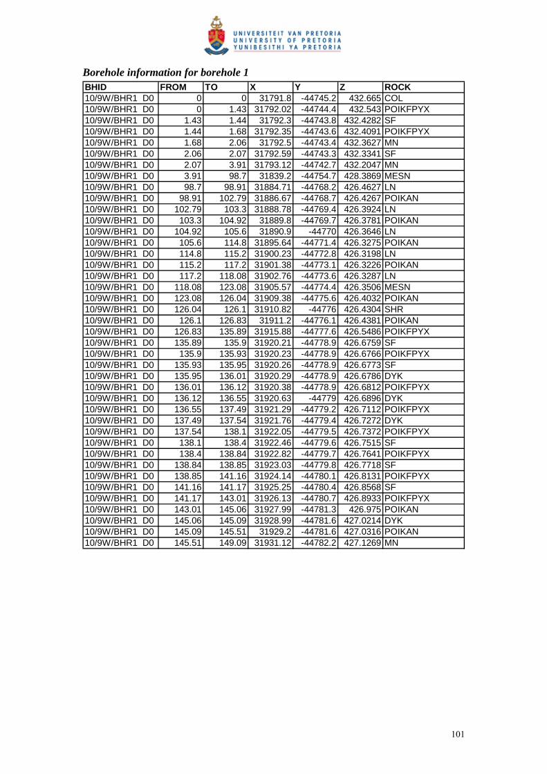
Borehole information for borehole 1 BHID FROM TO X Y Z ROCK10/9W/BHR1 D0 0 0 31791.8 -44745.2 432.665 COL10/9W/BHR1 D0 0 1.43 31792.02 -44744.4 432.543 POIKFPYX10/9W/BHR1 D0 1.43 1.44 31792.3 -44743.8 432.4282 SF10/9W/BHR1 D0 1.44 1.68 31792.35 -44743.6 432.4091 POIKFPYX10/9W/BHR1 D0 1.68 2.06 31792.5 -44743.4 432.3627 MN10/9W/BHR1 D0 2.06 2.07 31792.59 -44743.3 432.3341 SF10/9W/BHR1 D0 2.07 3.91 31793.12 -44742.7 432.2047 MN10/9W/BHR1 D0 3.91 98.7 31839.2 -44754.7 428.3869 MESN10/9W/BHR1 D0 98.7 98.91 31884.71 -44768.2 426.4627 LN10/9W/BHR1 D0 98.91 102.79 31886.67 -44768.7 426.4267 POIKAN10/9W/BHR1 D0 102.79 103.3 31888.78 -44769.4 426.3924 LN10/9W/BHR1 D0 103.3 104.92 31889.8 -44769.7 426.3781 POIKAN10/9W/BHR1 D0 104.92 105.6 31890.9 -44770 426.3646 LN10/9W/BHR1 D0 105.6 114.8 31895.64 -44771.4 426.3275 POIKAN10/9W/BHR1 D0 114.8 115.2 31900.23 -44772.8 426.3198 LN10/9W/BHR1 D0 115.2 117.2 31901.38 -44773.1 426.3226 POIKAN10/9W/BHR1 D0 117.2 118.08 31902.76 -44773.6 426.3287 LN10/9W/BHR1 D0 118.08 123.08 31905.57 -44774.4 426.3506 MESN10/9W/BHR1 D0 123.08 126.04 31909.38 -44775.6 426.4032 POIKAN10/9W/BHR1 D0 126.04 126.1 31910.82 -44776 426.4304 SHR10/9W/BHR1 D0 126.1 126.83 31911.2 -44776.1 426.4381 POIKAN10/9W/BHR1 D0 126.83 135.89 31915.88 -44777.6 426.5486 POIKFPYX10/9W/BHR1 D0 135.89 135.9 31920.21 -44778.9 426.6759 SF10/9W/BHR1 D0 135.9 135.93 31920.23 -44778.9 426.6766 POIKFPYX10/9W/BHR1 D0 135.93 135.95 31920.26 -44778.9 426.6773 SF10/9W/BHR1 D0 135.95 136.01 31920.29 -44778.9 426.6786 DYK10/9W/BHR1 D0 136.01 136.12 31920.38 -44778.9 426.6812 POIKFPYX10/9W/BHR1 D0 136.12 136.55 31920.63 -44779 426.6896 DYK10/9W/BHR1 D0 136.55 137.49 31921.29 -44779.2 426.7112 POIKFPYX10/9W/BHR1 D0 137.49 137.54 31921.76 -44779.4 426.7272 DYK10/9W/BHR1 D0 137.54 138.1 31922.05 -44779.5 426.7372 POIKFPYX10/9W/BHR1 D0 138.1 138.4 31922.46 -44779.6 426.7515 SF10/9W/BHR1 D0 138.4 138.84 31922.82 -44779.7 426.7641 POIKFPYX10/9W/BHR1 D0 138.84 138.85 31923.03 -44779.8 426.7718 SF10/9W/BHR1 D0 138.85 141.16 31924.14 -44780.1 426.8131 POIKFPYX10/9W/BHR1 D0 141.16 141.17 31925.25 -44780.4 426.8568 SF10/9W/BHR1 D0 141.17 143.01 31926.13 -44780.7 426.8933 POIKFPYX10/9W/BHR1 D0 143.01 145.06 31927.99 -44781.3 426.975 POIKAN10/9W/BHR1 D0 145.06 145.09 31928.99 -44781.6 427.0214 DYK10/9W/BHR1 D0 145.09 145.51 31929.2 -44781.6 427.0316 POIKAN10/9W/BHR1 D0 145.51 149.09 31931.12 -44782.2 427.1269 MN
101

Borehole information for borehole 2 BHID FROM TO X Y Z ROCK10/9W/BHR2 D0 0 0 31791 -44744 433.14 COL10/9W/BHR2 D0 0 0.44 31791.02 -44743.8 433.1676 MN10/9W/BHR2 D0 0.44 1.06 31791.1 -44743.2 433.2339 FRAC10/9W/BHR2 D0 1.06 3.03 31791.45 -44742 433.3961 MN10/9W/BHR2 D0 3.03 3.21 31791.92 -44741.1 433.5328 MESN10/9W/BHR2 D0 3.21 3.22 31791.97 -44741 433.5452 FRAC10/9W/BHR2 D0 3.22 4.44 31792.32 -44740.6 433.6259 MESN10/9W/BHR2 D0 4.44 4.7 31792.82 -44740.1 433.7263 FRAC10/9W/BHR2 D0 4.7 6.71 31793.77 -44739.4 433.889 MESN10/9W/BHR2 D0 6.71 7.14 31794.9 -44738.9 434.0543 FRAC10/9W/BHR2 D0 7.14 8.17 31795.57 -44738.6 434.1497 LN10/9W/BHR2 D0 8.17 8.26 31796.09 -44738.4 434.223 FRAC10/9W/BHR2 D0 8.26 9.79 31796.84 -44738.2 434.3289 LN10/9W/BHR2 D0 9.79 9.84 31797.58 -44737.9 434.4321 FRAC10/9W/BHR2 D0 9.84 9.94 31797.65 -44737.9 434.4419 LN10/9W/BHR2 D0 9.94 9.98 31797.71 -44737.9 434.4511 FRAC10/9W/BHR2 D0 9.98 10.59 31798.02 -44737.8 434.4936 LN10/9W/BHR2 D0 10.59 11.63 31798.8 -44737.5 434.6015 MESN10/9W/BHR2 D0 11.63 11.93 31799.44 -44737.3 434.6891 OLVN10/9W/BHR2 D0 11.93 14.51 31800.82 -44737 434.8776 MESN10/9W/BHR2 D0 14.51 14.57 31802.09 -44736.6 435.0514 FRAC10/9W/BHR2 D0 14.57 14.92 31802.28 -44736.6 435.0784 MESN10/9W/BHR2 D0 14.92 15.01 31802.49 -44736.5 435.1075 FRAC10/9W/BHR2 D0 15.01 15.46 31802.75 -44736.5 435.1432 MESN10/9W/BHR2 D0 15.46 16.8 31803.61 -44736.2 435.262 MN10/9W/BHR2 D0 16.8 17.59 31804.63 -44736 435.4038 MESN10/9W/BHR2 D0 17.59 17.76 31805.09 -44735.9 435.468 FRAC10/9W/BHR2 D0 17.76 23.29 31807.83 -44735.2 435.8526 MESN10/9W/BHR2 D0 23.29 23.35 31810.51 -44734.5 436.2365 FRAC10/9W/BHR2 D0 23.35 24.8 31811.24 -44734.3 436.3414 MESN10/9W/BHR2 D0 24.8 25 31812.03 -44734.1 436.4567 LN10/9W/BHR2 D0 25 25.05 31812.15 -44734.1 436.4742 FRAC10/9W/BHR2 D0 25.05 27.71 31813.46 -44733.8 436.6655 LN10/9W/BHR2 D0 27.71 37.84 31819.6 -44732.3 437.5977 MESN10/9W/BHR2 D0 37.84 37.93 31824.52 -44731.1 438.3833 FRAC10/9W/BHR2 D0 37.93 49.89 31830.31 -44729.8 439.3584 MESN10/9W/BHR2 D0 49.89 49.98 31836.1 -44728.5 440.3924 FRAC10/9W/BHR2 D0 49.98 50.81 31836.55 -44728.4 440.4734 MESN10/9W/BHR2 D0 50.81 50.83 31836.96 -44728.3 440.5484 FRAC10/9W/BHR2 D0 50.83 50.89 31836.99 -44728.3 440.5555 LN10/9W/BHR2 D0 50.89 53.08 31838.07 -44728 440.7553 MESN10/9W/BHR2 D0 53.08 53.13 31839.15 -44727.8 440.9556 FRAC10/9W/BHR2 D0 53.13 53.26 31839.24 -44727.8 440.9717 MESN10/9W/BHR2 D0 53.26 54.07 31839.69 -44727.7 441.0563 LN10/9W/BHR2 D0 54.07 55.56 31840.79 -44727.5 441.2643 MESN10/9W/BHR2 D0 55.56 60.67 31843.96 -44726.8 441.8716 LN10/9W/BHR2 D0 60.67 60.7 31846.43 -44726.2 442.3554 FRAC10/9W/BHR2 D0 60.7 60.93 31846.56 -44726.2 442.3802 MESN10/9W/BHR2 D0 60.93 60.98 31846.69 -44726.2 442.4068 FRAC10/9W/BHR2 D0 60.98 61.64 31847.03 -44726.1 442.4745 MESN10/9W/BHR2 D0 61.64 61.67 31847.37 -44726 442.5405 FRAC10/9W/BHR2 D0 61.67 61.77 31847.43 -44726 442.5529 MESN10/9W/BHR2 D0 61.77 61.82 31847.5 -44726 442.5673 FRAC10/9W/BHR2 D0 61.82 61.89 31847.56 -44726 442.5788 MESN10/9W/BHR2 D0 61.89 61.91 31847.6 -44726 442.5874 FRAC10/9W/BHR2 D0 61.91 64.83 31849.01 -44725.7 442.8709 MESN10/9W/BHR2 D0 64.83 64.86 31850.43 -44725.4 443.1585 FRAC10/9W/BHR2 D0 64.86 65.18 31850.6 -44725.4 443.1928 MESN10/9W/BHR2 D0 65.18 65.21 31850.77 -44725.3 443.2272 FRAC10/9W/BHR2 D0 65.21 66.22 31851.27 -44725.2 443.3296 MESN10/9W/BHR2 D0 66.22 71.88 31854.47 -44724.6 443.9966 POIKAN10/9W/BHR2 D0 71.88 72.71 31857.59 -44724 444.6639 MESN10/9W/BHR2 D0 72.71 76.41 31859.76 -44723.6 445.1404 POIKAN10/9W/BHR2 D0 76.41 76.76 31861.7 -44723.2 445.5738 POIKPYX10/9W/BHR2 D0 76.76 83.53 31865.08 -44722.4 446.352 POIKPYX10/9W/BHR2 D0 83.53 83.66 31868.37 -44721.7 447.1235 FRAC10/9W/BHR2 D0 83.66 104.18 31878.17 -44719.5 449.5288 POIKPYX10/9W/BHR2 D0 104.18 104.28 31887.95 -44717.4 451.9963 FRAC10/9W/BHR2 D0 104.28 104.62 31888.16 -44717.3 452.049 POIKAN10/9W/BHR2 D0 104.62 104.7 31888.36 -44717.3 452.0995 FRAC10/9W/BHR2 D0 104.7 106.17 31889.09 -44717.1 452.2856 POIKAN10/9W/BHR2 D0 106.17 110.27 31891.74 -44716.6 452.9576 FRAC10/9W/BHR2 D0 110.27 110.64 31893.86 -44716.1 453.4983 POIKPYX
102
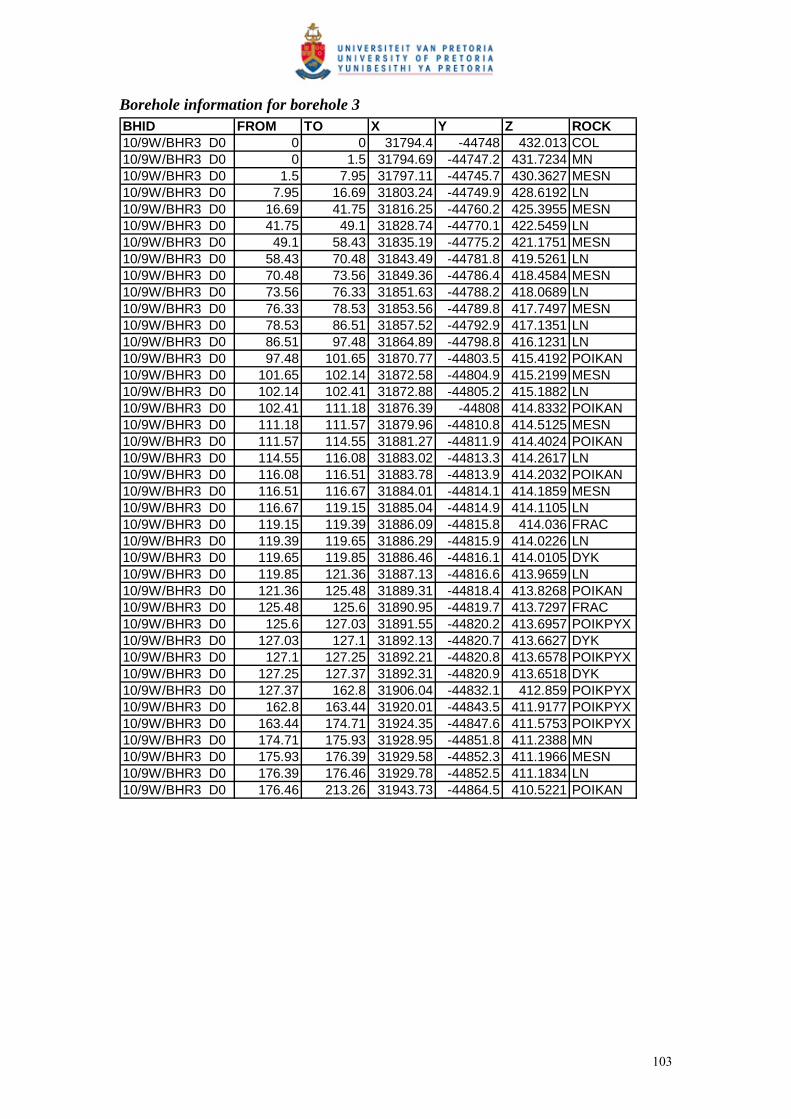
Borehole information for borehole 3 BHID FROM TO X Y Z ROCK10/9W/BHR3 D0 0 0 31794.4 -44748 432.013 COL10/9W/BHR3 D0 0 1.5 31794.69 -44747.2 431.7234 MN10/9W/BHR3 D0 1.5 7.95 31797.11 -44745.7 430.3627 MESN10/9W/BHR3 D0 7.95 16.69 31803.24 -44749.9 428.6192 LN10/9W/BHR3 D0 16.69 41.75 31816.25 -44760.2 425.3955 MESN10/9W/BHR3 D0 41.75 49.1 31828.74 -44770.1 422.5459 LN10/9W/BHR3 D0 49.1 58.43 31835.19 -44775.2 421.1751 MESN10/9W/BHR3 D0 58.43 70.48 31843.49 -44781.8 419.5261 LN10/9W/BHR3 D0 70.48 73.56 31849.36 -44786.4 418.4584 MESN10/9W/BHR3 D0 73.56 76.33 31851.63 -44788.2 418.0689 LN10/9W/BHR3 D0 76.33 78.53 31853.56 -44789.8 417.7497 MESN10/9W/BHR3 D0 78.53 86.51 31857.52 -44792.9 417.1351 LN10/9W/BHR3 D0 86.51 97.48 31864.89 -44798.8 416.1231 LN10/9W/BHR3 D0 97.48 101.65 31870.77 -44803.5 415.4192 POIKAN10/9W/BHR3 D0 101.65 102.14 31872.58 -44804.9 415.2199 MESN10/9W/BHR3 D0 102.14 102.41 31872.88 -44805.2 415.1882 LN10/9W/BHR3 D0 102.41 111.18 31876.39 -44808 414.8332 POIKAN10/9W/BHR3 D0 111.18 111.57 31879.96 -44810.8 414.5125 MESN10/9W/BHR3 D0 111.57 114.55 31881.27 -44811.9 414.4024 POIKAN10/9W/BHR3 D0 114.55 116.08 31883.02 -44813.3 414.2617 LN10/9W/BHR3 D0 116.08 116.51 31883.78 -44813.9 414.2032 POIKAN10/9W/BHR3 D0 116.51 116.67 31884.01 -44814.1 414.1859 MESN10/9W/BHR3 D0 116.67 119.15 31885.04 -44814.9 414.1105 LN10/9W/BHR3 D0 119.15 119.39 31886.09 -44815.8 414.036 FRAC10/9W/BHR3 D0 119.39 119.65 31886.29 -44815.9 414.0226 LN10/9W/BHR3 D0 119.65 119.85 31886.46 -44816.1 414.0105 DYK10/9W/BHR3 D0 119.85 121.36 31887.13 -44816.6 413.9659 LN10/9W/BHR3 D0 121.36 125.48 31889.31 -44818.4 413.8268 POIKAN10/9W/BHR3 D0 125.48 125.6 31890.95 -44819.7 413.7297 FRAC10/9W/BHR3 D0 125.6 127.03 31891.55 -44820.2 413.6957 POIKPYX10/9W/BHR3 D0 127.03 127.1 31892.13 -44820.7 413.6627 DYK10/9W/BHR3 D0 127.1 127.25 31892.21 -44820.8 413.6578 POIKPYX10/9W/BHR3 D0 127.25 127.37 31892.31 -44820.9 413.6518 DYK10/9W/BHR3 D0 127.37 162.8 31906.04 -44832.1 412.859 POIKPYX10/9W/BHR3 D0 162.8 163.44 31920.01 -44843.5 411.9177 POIKPYX10/9W/BHR3 D0 163.44 174.71 31924.35 -44847.6 411.5753 POIKPYX10/9W/BHR3 D0 174.71 175.93 31928.95 -44851.8 411.2388 MN10/9W/BHR3 D0 175.93 176.39 31929.58 -44852.3 411.1966 MESN10/9W/BHR3 D0 176.39 176.46 31929.78 -44852.5 411.1834 LN10/9W/BHR3 D0 176.46 213.26 31943.73 -44864.5 410.5221 POIKAN
103
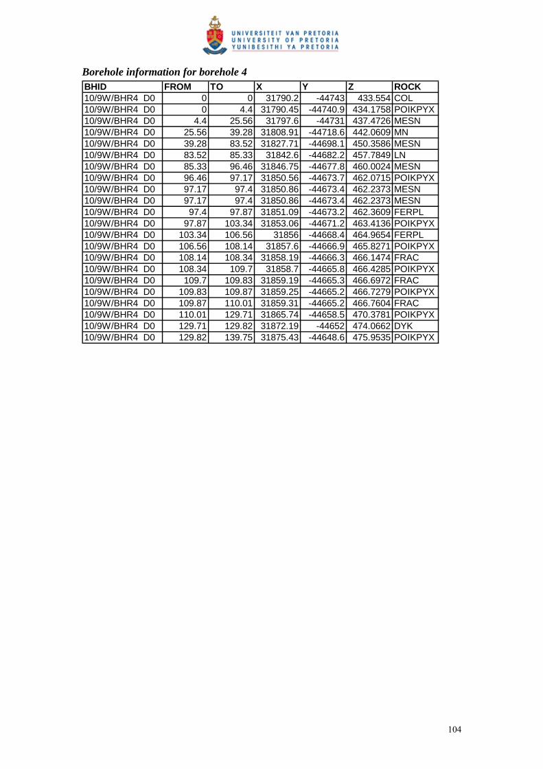
Borehole information for borehole 4 BHID FROM TO X Y Z ROCK10/9W/BHR4 D0 0 0 31790.2 -44743 433.554 COL10/9W/BHR4 D0 0 4.4 31790.45 -44740.9 434.1758 POIKPYX10/9W/BHR4 D0 4.4 25.56 31797.6 -44731 437.4726 MESN10/9W/BHR4 D0 25.56 39.28 31808.91 -44718.6 442.0609 MN10/9W/BHR4 D0 39.28 83.52 31827.71 -44698.1 450.3586 MESN10/9W/BHR4 D0 83.52 85.33 31842.6 -44682.2 457.7849 LN10/9W/BHR4 D0 85.33 96.46 31846.75 -44677.8 460.0024 MESN10/9W/BHR4 D0 96.46 97.17 31850.56 -44673.7 462.0715 POIKPYX10/9W/BHR4 D0 97.17 97.4 31850.86 -44673.4 462.2373 MESN10/9W/BHR4 D0 97.17 97.4 31850.86 -44673.4 462.2373 MESN10/9W/BHR4 D0 97.4 97.87 31851.09 -44673.2 462.3609 FERPL10/9W/BHR4 D0 97.87 103.34 31853.06 -44671.2 463.4136 POIKPYX10/9W/BHR4 D0 103.34 106.56 31856 -44668.4 464.9654 FERPL10/9W/BHR4 D0 106.56 108.14 31857.6 -44666.9 465.8271 POIKPYX10/9W/BHR4 D0 108.14 108.34 31858.19 -44666.3 466.1474 FRAC10/9W/BHR4 D0 108.34 109.7 31858.7 -44665.8 466.4285 POIKPYX10/9W/BHR4 D0 109.7 109.83 31859.19 -44665.3 466.6972 FRAC10/9W/BHR4 D0 109.83 109.87 31859.25 -44665.2 466.7279 POIKPYX10/9W/BHR4 D0 109.87 110.01 31859.31 -44665.2 466.7604 FRAC10/9W/BHR4 D0 110.01 129.71 31865.74 -44658.5 470.3781 POIKPYX10/9W/BHR4 D0 129.71 129.82 31872.19 -44652 474.0662 DYK10/9W/BHR4 D0 129.82 139.75 31875.43 -44648.6 475.9535 POIKPYX
104
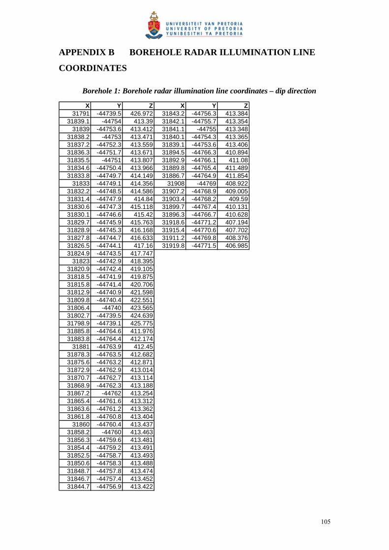
APPENDIX B BOREHOLE RADAR ILLUMINATION LINE
COORDINATES
Borehole 1: Borehole radar illumination line coordinates – dip direction
X Y Z X Y Z31791 -44739.5 426.972 31843.2 -44756.3 413.384
31839.1 -44754 413.39 31842.1 -44755.7 413.35431839 -44753.6 413.412 31841.1 -44755 413.348
31838.2 -44753 413.471 31840.1 -44754.3 413.36531837.2 -44752.3 413.559 31839.1 -44753.6 413.40631836.3 -44751.7 413.671 31894.5 -44766.3 410.89431835.5 -44751 413.807 31892.9 -44766.1 411.0831834.6 -44750.4 413.966 31889.8 -44765.4 411.48931833.8 -44749.7 414.149 31886.7 -44764.9 411.854
31833 -44749.1 414.356 31908 -44769 408.92231832.2 -44748.5 414.586 31907.2 -44768.9 409.00531831.4 -44747.9 414.84 31903.4 -44768.2 409.5931830.6 -44747.3 415.118 31899.7 -44767.4 410.13131830.1 -44746.6 415.42 31896.3 -44766.7 410.62831829.7 -44745.9 415.763 31918.6 -44771.2 407.19431828.9 -44745.3 416.168 31915.4 -44770.6 407.70231827.8 -44744.7 416.633 31911.2 -44769.8 408.37631826.5 -44744.1 417.16 31919.8 -44771.5 406.98531824.9 -44743.5 417.747
31823 -44742.9 418.39531820.9 -44742.4 419.10531818.5 -44741.9 419.87531815.8 -44741.4 420.70631812.9 -44740.9 421.59831809.8 -44740.4 422.55131806.4 -44740 423.56531802.7 -44739.5 424.63931798.9 -44739.1 425.77531885.8 -44764.6 411.97631883.8 -44764.4 412.174
31881 -44763.9 412.4531878.3 -44763.5 412.68231875.6 -44763.2 412.87131872.9 -44762.9 413.01431870.7 -44762.7 413.11431868.9 -44762.3 413.18831867.2 -44762 413.25431865.4 -44761.6 413.31231863.6 -44761.2 413.36231861.8 -44760.8 413.404
31860 -44760.4 413.43731858.2 -44760 413.46331856.3 -44759.6 413.48131854.4 -44759.2 413.49131852.5 -44758.7 413.49331850.6 -44758.3 413.48831848.7 -44757.8 413.47431846.7 -44757.4 413.45231844.7 -44756.9 413.422
105

Borehole 1: Borehole radar illumination line coordinates – strike direction
X Y Z X Y Z X Y Z31799.2 -44743.2 425.805 31856.9 -44754.4 414.819 31900.8 -44767.3 409.86331801.4 -44743.7 425.008 31857.7 -44754.6 414.915 31901.9 -44767.6 409.80731803.5 -44744.1 424.265 31858.6 -44754.9 414.969 31902.9 -44767.8 409.75731805.4 -44744.5 423.576 31859.4 -44755.2 414.982 31904 -44768.1 409.70831807.1 -44744.9 422.941 31860.2 -44755.6 414.983 31905.2 -44768.6 409.5431808.7 -44745.2 422.359 31861 -44756 414.97 31906.5 -44769.3 409.29231810.1 -44745.6 421.831 31861.8 -44756.4 414.945 31907.8 -44769.9 409.00831811.3 -44745.8 421.354 31862.6 -44756.7 414.905 31909.3 -44770.5 408.68831812.4 -44746.1 420.928 31863.4 -44757.1 414.852 31910.8 -44771.1 408.32731813.2 -44746.4 420.55 31864.2 -44757.4 414.786 31912.5 -44771.7 407.922
31814 -44746.6 420.203 31864.9 -44757.8 414.705 31914.2 -44772.3 407.47331814.8 -44746.8 419.86 31865.6 -44758.1 414.61 31916 -44772.9 406.97831815.7 -44746.9 419.504 31866.4 -44758.4 414.515 31916.4 -44773.1 406.83131816.5 -44747.1 419.133 31867.1 -44758.7 414.43 31917.9 -44773.5 406.43831817.4 -44747.3 418.747 31867.8 -44758.9 414.34 31919.8 -44774.1 405.87531818.3 -44747.5 418.347 31868.6 -44759.2 414.24431819.3 -44747.7 417.932 31869.3 -44759.5 414.14231820.2 -44747.9 417.503 31870.1 -44759.7 414.03431821.3 -44748.2 417.059 31870.9 -44760 413.9231822.3 -44748.4 416.6 31871.7 -44760.2 413.831823.3 -44748.6 416.164 31872.5 -44760.5 413.67431824.4 -44748.4 415.856 31873.3 -44760.7 413.54131825.5 -44748.3 415.592 31874.1 -44761 413.40231826.6 -44748.3 415.362 31874.9 -44761.3 413.25531827.8 -44748.2 415.165 31875.8 -44761.5 413.101
31829 -44748.2 415.002 31876.7 -44761.8 412.93931830.3 -44748.3 414.872 31877.6 -44762.1 412.7731831.6 -44748.4 414.775 31878.5 -44762.3 412.59331832.9 -44748.5 414.71 31879.4 -44762.6 412.40731834.3 -44748.6 414.677 31880.4 -44762.9 412.21531835.8 -44748.9 414.668 31881.4 -44763.2 412.01431837.2 -44749.2 414.621 31882.4 -44763.5 411.80531838.7 -44749.6 414.572 31883.4 -44763.7 411.597
31840 -44749.9 414.53 31884.4 -44763.9 411.42631841.4 -44750.3 414.485 31885.1 -44764 411.31931842.7 -44750.7 414.447 31885.4 -44764.1 411.26931843.9 -44751 414.417 31886.4 -44764.3 411.12331845.1 -44751.3 414.395 31887.4 -44764.5 410.98731846.3 -44751.6 414.379 31888.5 -44764.6 410.86131847.4 -44751.9 414.371 31889.5 -44764.8 410.74431848.5 -44752.2 414.371 31890.5 -44765 410.63831849.5 -44752.5 414.383 31891.5 -44765.2 410.5431850.5 -44752.8 414.406 31892.5 -44765.4 410.45331851.5 -44753 414.437 31893.6 -44765.6 410.37331852.5 -44753.2 414.478 31894.6 -44765.8 410.28931853.4 -44753.5 414.528 31895.6 -44766.1 410.20931854.3 -44753.7 414.587 31896.7 -44766.3 410.12931855.2 -44753.9 414.655 31897.7 -44766.6 410.05531856.1 -44754.1 414.732 31898.8 -44766.8 409.986
106
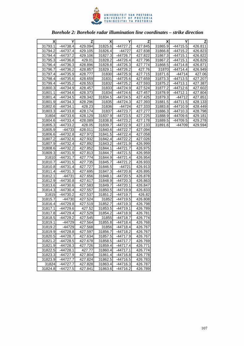
Borehole 2: Borehole radar illumination line coordinates – strike direction
X Y Z X Y Z X Y Z31793.1 -44738.4 429.094 31825.6 -44727.2 427.845 31865.9 -44715.5 426.81131794.2 -44737.4 429.105 31826.4 -44727 427.838 31866.8 -44715.2 426.82331794.4 -44737.2 429.106 31827.3 -44726.7 427.822 31867.3 -44715.1 426.82231795.3 -44736.8 429.01 31828.2 -44726.4 427.796 31867.2 -44715.1 426.82931796.4 -44736.3 428.896 31828.8 -44726.3 427.774 31868.5 -44714.8 426.87131796.7 -44736.2 428.857 31829.1 -44726.2 427.76 31870 -44714.4 426.94931797.4 -44735.9 428.777 31830 -44725.9 427.715 31871.6 -44714 427.0631798.4 -44735.6 428.659 31831 -44725.6 427.659 31873.3 -44713.5 427.20731799.4 -44735.2 428.553 31832 -44725.2 427.593 31875.2 -44713.1 427.38731800.3 -44734.9 428.457 31833 -44724.9 427.524 31877.2 -44712.6 427.60231801.1 -44734.6 428.373 31834 -44724.6 427.457 31878.9 -44712.1 427.80431801.4 -44734.5 428.342 31834.5 -44724.5 427.425 31879.3 -44712 427.85131801.9 -44734.3 428.296 31835 -44724.3 427.393 31881.5 -44711.5 428.13331802.6 -44734.1 428.23 31836 -44724 427.333 31883.8 -44710.9 428.44931803.3 -44733.8 428.174 31837 -44723.7 427.277 31886.3 -44710.3 428.798
31804 -44733.6 428.129 31837.9 -44723.5 427.225 31888.9 -44709.6 429.18131804.6 -44733.4 428.089 31838.8 -44723.2 427.178 31889.5 -44709.5 429.27831805.3 -44733.2 428.05 31839.7 -44722.9 427.133 31891.6 -44709 429.59431805.9 -44733 428.011 31840.6 -44722.7 427.09431806.6 -44732.8 427.972 31841.5 -44722.4 427.05831807.2 -44732.6 427.932 31842.4 -44722.2 427.02631807.9 -44732.4 427.892 31843.2 -44721.9 426.99931808.6 -44732.2 427.852 31844.1 -44721.7 426.97531809.3 -44731.9 427.813 31844.7 -44721.5 426.959
31810 -44731.7 427.774 31844.9 -44721.4 426.95431810.7 -44731.5 427.735 31845.7 -44721.2 426.93331810.8 -44731.4 427.727 31846.5 -44721 426.91331811.4 -44731.3 427.695 31847.3 -44720.8 426.89531812.1 -44731 427.656 31848.1 -44720.5 426.87831812.9 -44730.8 427.617 31848.9 -44720.3 426.86331813.6 -44730.6 427.583 31849.7 -44720.1 426.84731814.3 -44730.4 427.557 31850.5 -44719.9 426.833
31815 -44730.2 427.537 31851.2 -44719.7 426.8231815.7 -44730 427.524 31852 -44719.5 426.80831816.4 -44729.8 427.519 31852.7 -44719.3 426.79831817.1 -44729.6 427.52 31853.5 -44719.1 426.78931817.8 -44729.4 427.529 31854.2 -44718.9 426.78131818.5 -44729.2 427.545 31855 -44718.7 426.77431819.1 -44729 427.564 31855.8 -44718.4 426.76831819.2 -44729 427.568 31856 -44718.4 426.76731819.9 -44728.8 427.597 31856.7 -44718.2 426.76731820.5 -44728.7 427.634 31857.5 -44717.9 426.76731821.2 -44728.5 427.678 31858.5 -44717.7 426.76931821.9 -44728.3 427.726 31859.4 -44717.4 426.77131822.5 -44728.1 427.77 31860.4 -44717.1 426.77431823.3 -44727.9 427.804 31861.4 -44716.8 426.77831823.9 -44727.7 427.824 31862.5 -44716.5 426.783
31824 -44727.7 427.828 31863.4 -44716.3 426.78731824.8 -44727.5 427.841 31863.6 -44716.2 426.789
107

Borehole 3: Borehole radar illumination line coordinates – dip direction
X Y Z X Y Z X Y Z31802.7 -44747.4 419.844 31858.2 -44790.1 402.535 31916.9 -44834.7 387.4231815.6 -44757.3 416.084 31857.1 -44789.4 402.811 31915.7 -44833.9 387.76531814.4 -44756.4 416.469 31869.8 -44798.9 399.401 31914.4 -44833 388.095
31813 -44755.3 416.883 31869.6 -44798.8 399.445 31913.2 -44832.2 388.41131811.6 -44754.2 417.301 31868.8 -44798.2 399.687 31912.1 -44831.4 388.71331810.1 -44753.1 417.723 31867.9 -44797.5 399.931 31910.9 -44830.7 38931808.7 -44752 418.149 31866.9 -44796.8 400.179 31909.8 -44830 389.27331807.2 -44750.9 418.579 31866 -44796.1 400.429 31908.8 -44829.2 389.53131805.6 -44749.7 419.012 31865.1 -44795.4 400.682 31907.7 -44828.6 389.77531804.1 -44748.5 419.449 31864.1 -44794.7 400.939 31906.8 -44827.9 390.00531827.9 -44766.3 412.164 31871.6 -44800.3 398.914 31905.9 -44827.2 390.2331826.8 -44765.6 412.536 31871.4 -44800.1 398.97 31905 -44826.5 390.45131825.7 -44764.7 412.912 31870.5 -44799.5 399.206 31922.6 -44839.1 385.6531824.5 -44763.9 413.292 31875.4 -44803.2 397.851 31921.8 -44838.5 385.89531823.3 -44763 413.676 31874.7 -44802.7 398.054 31920.6 -44837.5 386.29831822.1 -44762.2 414.063 31873.9 -44802 398.279 31919.4 -44836.6 386.68631820.9 -44761.2 414.455 31873.1 -44801.4 398.506 31927 -44842.7 384.1531819.6 -44760.3 414.85 31872.2 -44800.8 398.737 31925.7 -44841.6 384.631818.4 -44759.4 415.249 31879 -44806.1 396.854 31924.4 -44840.6 385.04631817.1 -44758.4 415.652 31878.5 -44805.8 396.973 31923.1 -44839.5 385.47831815.7 -44757.4 416.058 31877.8 -44805.1 397.183 31934.7 -44848.4 381.6231834.3 -44771.1 409.857 31877 -44804.5 397.397 31933.1 -44847.2 382.15331833.9 -44770.8 410.007 31876.2 -44803.9 397.613 31931.5 -44846 382.671
31833 -44770.1 410.358 31883 -44809.4 395.768 31930 -44844.9 383.17531832.1 -44769.3 410.712 31882.3 -44808.8 395.962 31928.5 -44843.8 383.66531831.1 -44768.6 411.07 31881.5 -44808.2 396.15831830.1 -44767.9 411.431 31880.8 -44807.6 396.358
31829 -44767.1 411.795 31880 -44807 396.5631842.6 -44777.8 407 31879.3 -44806.4 396.76531841.7 -44777 407.313 31886.1 -44812 394.95131840.7 -44776.2 407.639 31885.9 -44811.8 395.02131839.7 -44775.4 407.967 31885.2 -44811.2 395.20431838.7 -44774.6 408.299 31884.5 -44810.6 395.38931837.8 -44773.9 408.634 31883.7 -44810 395.57731836.8 -44773.1 408.973 31890 -44815.2 394.01831835.8 -44772.3 409.314 31889.4 -44814.7 394.15131834.9 -44771.6 409.659 31888.7 -44814.1 394.3231848.5 -44782.6 405.174 31888 -44813.6 394.49131847.7 -44781.9 405.427 31887.3 -44813 394.66531846.7 -44781.1 405.734 31886.6 -44812.4 394.84231845.7 -44780.2 406.043 31904.8 -44826.4 390.4931844.7 -44779.4 406.356 31904.1 -44825.9 390.67131843.7 -44778.6 406.672 31903.2 -44825.2 390.88731852.8 -44786 403.971 31902.3 -44824.5 391.10131851.8 -44785.3 404.234 31901.5 -44823.9 391.31231850.8 -44784.4 404.528 31900.6 -44823.2 391.5231849.7 -44783.6 404.824 31899.8 -44822.6 391.72631848.7 -44782.7 405.124 31898.9 -44822 391.92931856.7 -44789 402.929 31898.1 -44821.3 392.12931856.1 -44788.6 403.09 31897.3 -44820.7 392.326
31855 -44787.8 403.372 31896.5 -44820.1 392.52131854 -44786.9 403.656 31895.6 -44819.5 392.713
31852.9 -44786.1 403.944 31894.8 -44818.9 392.90231864 -44794.6 400.975 31894 -44818.2 393.089
31863.2 -44793.9 401.197 31893.2 -44817.6 393.27331862.2 -44793.2 401.459 31892.5 -44817.1 393.45431861.2 -44792.5 401.724 31891.7 -44816.5 393.63231860.2 -44791.7 401.991 31890.9 -44815.9 393.80831859.2 -44790.9 402.262 31890.1 -44815.3 393.981
108

Borehole 3: Borehole radar illumination line coordinates – strike direction
X Y Z X Y Z X Y Z31800.1 -44746.3 421.041 31853 -44785.3 403.385 31891.2 -44813.9 393.7331801.7 -44747.3 420.477 31853.9 -44786 403.13 31892.2 -44814.7 393.442
31802 -44747.5 420.393 31854.9 -44786.6 402.88 31893.2 -44815.5 393.1531803.3 -44748.5 419.869 31855.8 -44787.3 402.634 31894.2 -44816.3 392.85231804.9 -44749.7 419.264 31856.7 -44787.9 402.392 31895.3 -44817.2 392.53431806.5 -44750.9 418.67 31857 -44788.1 402.322 31896.5 -44818.1 392.19531808.1 -44752.1 418.087 31857.6 -44788.5 402.153 31897.8 -44819.1 391.83531809.6 -44753.2 417.516 31858.6 -44789.2 401.918 31899.1 -44820.1 391.45331811.2 -44754.4 416.956 31859.5 -44789.8 401.686 31900.5 -44821.2 391.04831812.7 -44755.5 416.409 31860.4 -44790.5 401.457 31902 -44822.3 390.62231814.1 -44756.6 415.872 31861.3 -44791.1 401.231 31903.5 -44823.5 390.174
31815 -44757.2 415.581 31862.2 -44791.7 401.009 31905.1 -44824.7 389.73131815.6 -44757.7 415.348 31863.1 -44792.4 400.79 31905.2 -44824.7 389.704
31817 -44758.8 414.835 31864.1 -44793 400.575 31906.9 -44826 389.21531818.5 -44759.9 414.334 31864.9 -44793.6 400.391 31908.7 -44827.4 388.70331819.9 -44760.9 413.844 31865 -44793.6 400.362 31910.6 -44828.8 388.1731821.2 -44761.9 413.366 31865.9 -44794.3 400.154 31912.5 -44830.2 387.61431822.6 -44762.9 412.899 31866.8 -44794.9 399.949 31914.5 -44831.8 387.03731823.9 -44763.9 412.445 31867.7 -44795.5 399.747 31916.6 -44833.3 386.43731825.2 -44764.9 412.002 31868.6 -44796.2 399.548 31918.8 -44835 385.81531826.5 -44765.9 411.57 31869.5 -44796.8 399.353 31918.9 -44835.1 385.78531827.6 -44766.6 411.225 31870.4 -44797.4 399.16 31921.1 -44837 385.07131827.8 -44766.8 411.151 31871.2 -44797.9 399.006 31923.2 -44838.8 384.39831829.1 -44767.7 410.746 31871.3 -44798.1 398.971 31923.5 -44839.1 384.29931830.3 -44768.6 410.349 31872.3 -44798.7 398.787 31925.9 -44841.1 383.51931831.5 -44769.5 409.951 31873.1 -44799.3 398.604 31927.7 -44842.6 382.95731832.8 -44770.4 409.557 31874.1 -44800.1 398.36 31928.5 -44843.2 382.73
31834 -44771.3 409.171 31875 -44800.9 398.127 31931.1 -44845.3 381.95531834.2 -44771.5 409.114 31876 -44801.6 397.89131835.1 -44772.2 408.793 31876.7 -44802.2 397.70331836.3 -44773.1 408.422 31876.9 -44802.4 397.65331837.5 -44773.9 408.058 31877.9 -44803.1 397.41331838.6 -44774.8 407.701 31878.8 -44803.9 397.1731839.7 -44775.6 407.349 31879.8 -44804.7 396.92431840.8 -44776.4 407.004 31880.1 -44804.9 396.83331841.9 -44777.2 406.666 31880.7 -44805.4 396.67531842.5 -44777.7 406.488 31881.7 -44806.2 396.424
31843 -44778 406.335 31882.6 -44807 396.16931844.1 -44778.8 406.01 31883.6 -44807.7 395.91231845.1 -44779.6 405.691 31883.9 -44808 395.8131846.2 -44780.3 405.379 31884.5 -44808.5 395.65131847.2 -44781.1 405.074 31885.5 -44809.3 395.38631848.2 -44781.8 404.776 31886.4 -44810 395.11831848.5 -44782 404.69 31886.8 -44810.4 394.99531849.2 -44782.5 404.484 31887.4 -44810.8 394.84631850.2 -44783.3 404.199 31888.3 -44811.6 394.57231851.1 -44784 403.921 31889.3 -44812.4 394.29531852.1 -44784.6 403.649 31890.3 -44813.2 394.01531852.8 -44785.2 403.443 31890.4 -44813.3 393.966
109
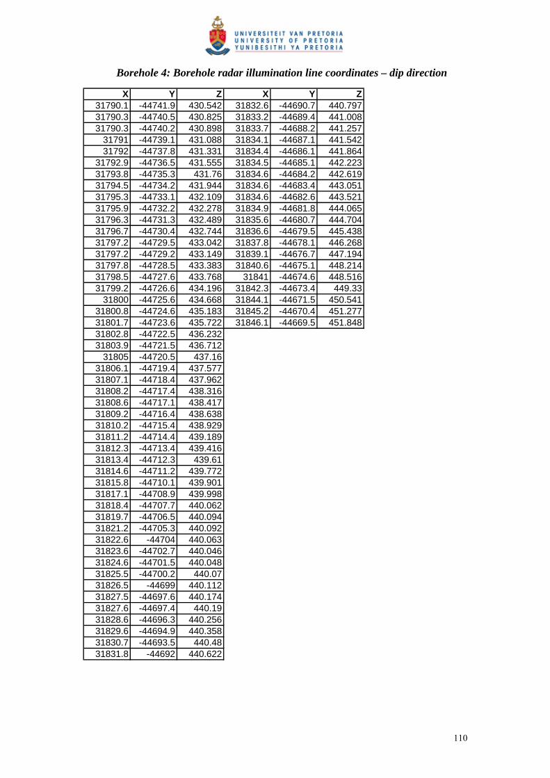
Borehole 4: Borehole radar illumination line coordinates – dip direction
X Y Z X Y Z31790.1 -44741.9 430.542 31832.6 -44690.7 440.79731790.3 -44740.5 430.825 31833.2 -44689.4 441.00831790.3 -44740.2 430.898 31833.7 -44688.2 441.257
31791 -44739.1 431.088 31834.1 -44687.1 441.54231792 -44737.8 431.331 31834.4 -44686.1 441.864
31792.9 -44736.5 431.555 31834.5 -44685.1 442.22331793.8 -44735.3 431.76 31834.6 -44684.2 442.61931794.5 -44734.2 431.944 31834.6 -44683.4 443.05131795.3 -44733.1 432.109 31834.6 -44682.6 443.52131795.9 -44732.2 432.278 31834.9 -44681.8 444.06531796.3 -44731.3 432.489 31835.6 -44680.7 444.70431796.7 -44730.4 432.744 31836.6 -44679.5 445.43831797.2 -44729.5 433.042 31837.8 -44678.1 446.26831797.2 -44729.2 433.149 31839.1 -44676.7 447.19431797.8 -44728.5 433.383 31840.6 -44675.1 448.21431798.5 -44727.6 433.768 31841 -44674.6 448.51631799.2 -44726.6 434.196 31842.3 -44673.4 449.33
31800 -44725.6 434.668 31844.1 -44671.5 450.54131800.8 -44724.6 435.183 31845.2 -44670.4 451.27731801.7 -44723.6 435.722 31846.1 -44669.5 451.84831802.8 -44722.5 436.23231803.9 -44721.5 436.712
31805 -44720.5 437.1631806.1 -44719.4 437.57731807.1 -44718.4 437.96231808.2 -44717.4 438.31631808.6 -44717.1 438.41731809.2 -44716.4 438.63831810.2 -44715.4 438.92931811.2 -44714.4 439.18931812.3 -44713.4 439.41631813.4 -44712.3 439.6131814.6 -44711.2 439.77231815.8 -44710.1 439.90131817.1 -44708.9 439.99831818.4 -44707.7 440.06231819.7 -44706.5 440.09431821.2 -44705.3 440.09231822.6 -44704 440.06331823.6 -44702.7 440.04631824.6 -44701.5 440.04831825.5 -44700.2 440.0731826.5 -44699 440.11231827.5 -44697.6 440.17431827.6 -44697.4 440.1931828.6 -44696.3 440.25631829.6 -44694.9 440.35831830.7 -44693.5 440.4831831.8 -44692 440.622
110
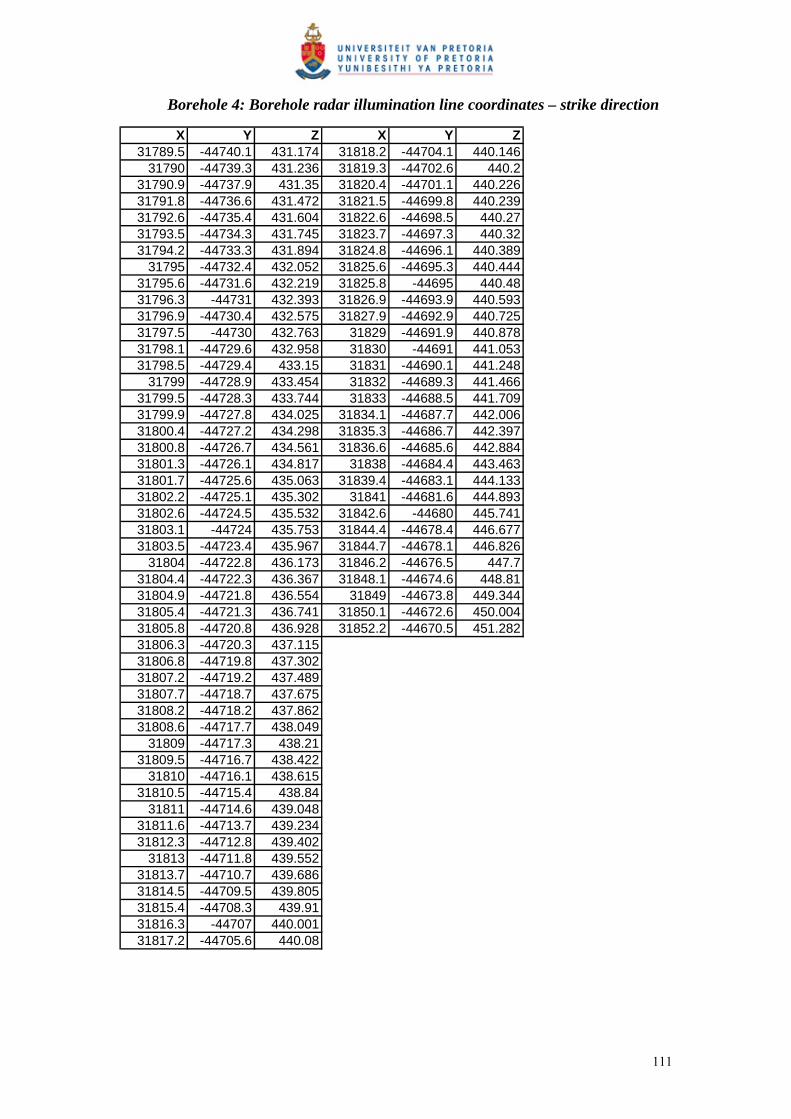
Borehole 4: Borehole radar illumination line coordinates – strike direction
X Y Z X Y Z31789.5 -44740.1 431.174 31818.2 -44704.1 440.146
31790 -44739.3 431.236 31819.3 -44702.6 440.231790.9 -44737.9 431.35 31820.4 -44701.1 440.22631791.8 -44736.6 431.472 31821.5 -44699.8 440.23931792.6 -44735.4 431.604 31822.6 -44698.5 440.2731793.5 -44734.3 431.745 31823.7 -44697.3 440.3231794.2 -44733.3 431.894 31824.8 -44696.1 440.389
31795 -44732.4 432.052 31825.6 -44695.3 440.44431795.6 -44731.6 432.219 31825.8 -44695 440.4831796.3 -44731 432.393 31826.9 -44693.9 440.59331796.9 -44730.4 432.575 31827.9 -44692.9 440.72531797.5 -44730 432.763 31829 -44691.9 440.87831798.1 -44729.6 432.958 31830 -44691 441.05331798.5 -44729.4 433.15 31831 -44690.1 441.248
31799 -44728.9 433.454 31832 -44689.3 441.46631799.5 -44728.3 433.744 31833 -44688.5 441.70931799.9 -44727.8 434.025 31834.1 -44687.7 442.00631800.4 -44727.2 434.298 31835.3 -44686.7 442.39731800.8 -44726.7 434.561 31836.6 -44685.6 442.88431801.3 -44726.1 434.817 31838 -44684.4 443.46331801.7 -44725.6 435.063 31839.4 -44683.1 444.13331802.2 -44725.1 435.302 31841 -44681.6 444.89331802.6 -44724.5 435.532 31842.6 -44680 445.74131803.1 -44724 435.753 31844.4 -44678.4 446.67731803.5 -44723.4 435.967 31844.7 -44678.1 446.826
31804 -44722.8 436.173 31846.2 -44676.5 447.731804.4 -44722.3 436.367 31848.1 -44674.6 448.8131804.9 -44721.8 436.554 31849 -44673.8 449.34431805.4 -44721.3 436.741 31850.1 -44672.6 450.00431805.8 -44720.8 436.928 31852.2 -44670.5 451.28231806.3 -44720.3 437.11531806.8 -44719.8 437.30231807.2 -44719.2 437.48931807.7 -44718.7 437.67531808.2 -44718.2 437.86231808.6 -44717.7 438.049
31809 -44717.3 438.2131809.5 -44716.7 438.422
31810 -44716.1 438.61531810.5 -44715.4 438.84
31811 -44714.6 439.04831811.6 -44713.7 439.23431812.3 -44712.8 439.402
31813 -44711.8 439.55231813.7 -44710.7 439.68631814.5 -44709.5 439.80531815.4 -44708.3 439.9131816.3 -44707 440.00131817.2 -44705.6 440.08
111


![Deep Borehole Field Test Laboratory and Borehole Testing ... · The characterization borehole (CB) is the smaller-diameter borehole (i.e., 21.6 cm [8.5”] diameter at total depth),](https://img.pdfslide.us/doc/110x75/5ebe68817151f10bcd35645a/deep-borehole-field-test-laboratory-and-borehole-testing-the-characterization.jpg)

![KLOT in Romeoville, Illinois USING RADAR [NEXRAD] TO DELINEATE MIGRATORY BIRD MOVEMENT CORRIDORS](https://img.pdfslide.us/doc/110x75/5a4d1ad17f8b9ab059971599/klot-in-romeoville-illinois-using-radar-nexrad-to-delineate-migratory-bird.jpg)