Embed Size (px)
Citation preview
67
ISSN 1392 - 1207. MECHANIKA. 2010. Nr.4(84)
The filler wire - laser beam interaction during laser welding with low alloyed steel filler wire
A. Salminen Lappeenranta University of Technology, Skinnarilankatu 34, 53850 Lappeenranta, Finland, E-mail: [email protected] Machine Technology Centre Turku Ltd, Lemminkäisenkatu 28, 20520 Turku, Finland 1. Introduction 1.1. Laser welding
Laser welding is usually performed in the key-hole-welding mode. The high power density required for keyhole welding of steels is achieved by focusing the laser beam power (>1 kW) to a small focus spot of diameter 0.1 – 0.5 mm. The heat absorbed from the laser beam to the workpiece heats the material, melting it and finally vapor-izing it. The use of laser welding has so far been popular in applications were high weld quality or production through-put is required. The industrial utilization of laser welding has suffered from the stringent joint requirements. The use of filler material with laser welding makes the joint toler-ances less severe. Owing to the restricted amount of infor-mation about the welding process with filler wire, the laser welding with filler wire is use seldom.
The major drawback of the laser welding process is the stringent joint requirements. In the case of a typical butt joint the widest acceptable air gap for autogenous laser welding is usually 10% of the material thickness. This re-quires usually the joint edges to be machined or laser cut. The tolerances can be fulfilled when components are rela-tively small and manufactured with machining or laser cutting. Even in these cases for large components it is dif-ficult to achieve the required accuracy when positioning them. The geometry of a joint, air gap and part mismatch varies from joint to joint and between products and produc-tion batches. Filling of the air gap requires additional mate-rial that should exist in the joint area during welding. The filler material is usually fed as a wire during welding.
Laser welding with filler wire is usually consid-ered to be too a difficult process for industrial application, having too many parameters and too stringent requirements for wire positioning. According to literature the studies have usually concentrated on the effect of filler material on the metallurgy and properties of the weld metal to solve the problems of one particular material and/or application.
1.2. Process efficiency
Energy input is different in laser welding com-
pared with conventional welding. The high intensity of the laser beam creates a deep narrow weld. When the laser energy is absorbed to the material through the wall of the keyhole, the heat is distributed evenly throughout the whole penetration depth. The cooling time for the critical temperature range of 800 - 500°C, t8/5, is considerably shorter for laser welding than for arc welding, which arises from low energy input caused by the nature of the keyhole
welding mode and small focal point. The small concen-trated energy input of laser welding creates a deep, narrow weld and heat affected zone (HAZ). This energy input mode results in a smaller grain size in the weld metal and HAZ and minimal distortions. Due to a high cooling rate the hardness of HAZ in C-Mn steels becomes a higher than in the arc welding.
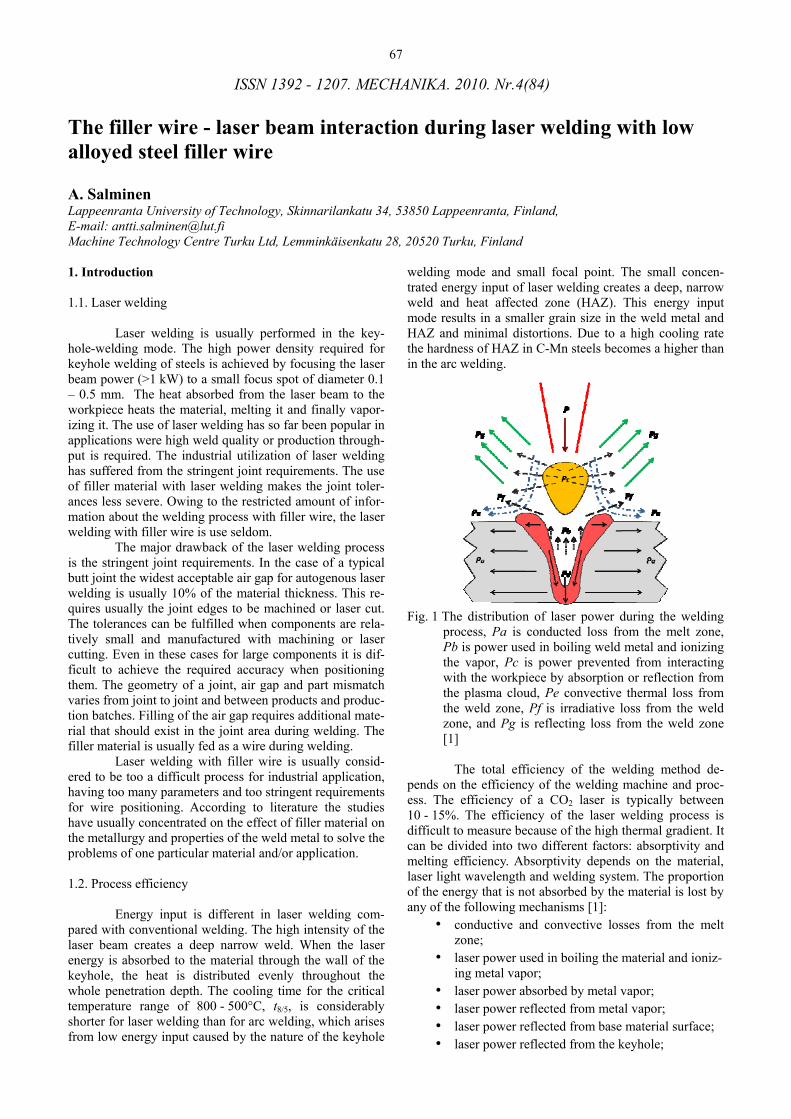
Fig. 1 The distribution of laser power during the welding
process, Pa is conducted loss from the melt zone, Pb is power used in boiling weld metal and ionizing the vapor, Pc is power prevented from interacting with the workpiece by absorption or reflection from the plasma cloud, Pe convective thermal loss from the weld zone, Pf is irradiative loss from the weld zone, and Pg is reflecting loss from the weld zone [1]
The total efficiency of the welding method de-
pends on the efficiency of the welding machine and proc-ess. The efficiency of a CO2 laser is typically between 10 - 15%. The efficiency of the laser welding process is difficult to measure because of the high thermal gradient. It can be divided into two different factors: absorptivity and melting efficiency. Absorptivity depends on the material, laser light wavelength and welding system. The proportion of the energy that is not absorbed by the material is lost by any of the following mechanisms [1]:
• conductive and convective losses from the melt zone;
• laser power used in boiling the material and ioniz-ing metal vapor;
• laser power absorbed by metal vapor; • laser power reflected from metal vapor; • laser power reflected from base material surface; • laser power reflected from the keyhole;
68
• heat radiation losses from the weld zone; • power passing through the keyhole.
Fig. 1 illustrates these different losses. They de-pend on material properties, laser beam properties and in-tensity. The power passing through can be minimized by optimization of parameters. Power losses through the key-hole increase with an increase in air gap in a butt joint [1].
Fig. 2 illustrates the fraction of power losses by reflection from the keyhole and base material depending on the welding speed [2].
Fig. 2 The change of keyhole and melt pool shape and la-
ser beam reflection with increasing welding speed [2]
1.3. Review of status of laser welding with filler wire
The problems caused to the welding process by a feed position error, transverse to the welding direction (WY) are obvious. In case of 2 mm wire diameter, the position error of WY = 0.25 mm will decrease the melting efficiency by 30% and 36% for wire diameters of 1.0, respectively [3]. This positioning error, WY, causes also asymmetrical weld bead [4].
Fig. 3 describes the geometrical parameters of the wire feeding and laser beam in comparison butt joint. The wire is usually fed to the leading edge of the keyhole (lead-ing feed, LF), which offers more evenly distributed filler
Fig. 3 The parameters of filler wire feed relative to the laser beam, workpiece surface and joint during laser welding
material in the weld metal [4]. However the dilution is with both leading (LF) and trailing feed (TF) when using high welding speeds (base material: mild steel, filler wire: aus-tenitic stainless steel) [5]. Also the requirements set by optical seam tracking may justify the use of trailing feed [6].
The optimum feed angle (αW) is within a wide range, 30°-75°, compared to the workpiece surface. The geometrical dimensions of the welding set up often define this range.
1.4. The phenomena affecting to use of filler wire There are some aspects in the laser welding and
laser - material interaction that can be considered to affect on the process performed with filler wire.
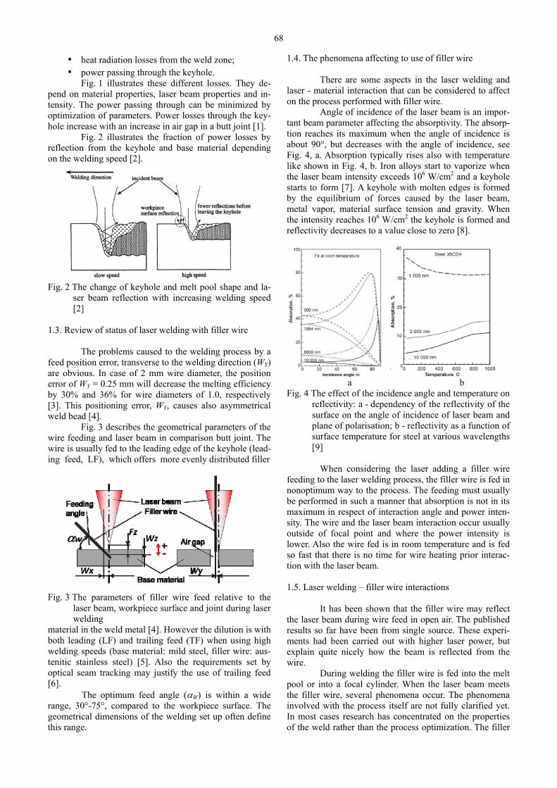
Angle of incidence of the laser beam is an impor-tant beam parameter affecting the absorptivity. The absorp-tion reaches its maximum when the angle of incidence is about 90°, but decreases with the angle of incidence, see Fig. 4, a. Absorption typically rises also with temperature like shown in Fig. 4, b. Iron alloys start to vaporize when the laser beam intensity exceeds 106 W/cm2 and a keyhole starts to form [7]. A keyhole with molten edges is formed by the equilibrium of forces caused by the laser beam, metal vapor, material surface tension and gravity. When the intensity reaches 106 W/cm2 the keyhole is formed and reflectivity decreases to a value close to zero [8].
a b Fig. 4 The effect of the incidence angle and temperature on
reflectivity: a - dependency of the reflectivity of the surface on the angle of incidence of laser beam and plane of polarisation; b - reflectivity as a function of surface temperature for steel at various wavelengths [9]
When considering the laser adding a filler wire
feeding to the laser welding process, the filler wire is fed in nonoptimum way to the process. The feeding must usually be performed in such a manner that absorption is not in its maximum in respect of interaction angle and power inten-sity. The wire and the laser beam interaction occur usually outside of focal point and where the power intensity is lower. Also the wire fed is in room temperature and is fed so fast that there is no time for wire heating prior interac-tion with the laser beam.
1.5. Laser welding – filler wire interactions
It has been shown that the filler wire may reflect
the laser beam during wire feed in open air. The published results so far have been from single source. These experi-ments had been carried out with higher laser power, but explain quite nicely how the beam is reflected from the wire.
During welding the filler wire is fed into the melt pool or into a focal cylinder. When the laser beam meets the filler wire, several phenomena occur. The phenomena involved with the process itself are not fully clarified yet. In most cases research has concentrated on the properties of the weld rather than the process optimization. The filler
69
wire should be fed towards the focal point of the laser beam [10]. Feeding takes place in the direction of the joint, at the trailing or leading edge of the keyhole. When the laser beam impinges on the filler wire, it absorbs part of the power, part of it passes through the wire and part of it is reflected away [3]. The fraction of the reflected laser power depends on the beam power, the wire feed rate, the wire - beam interaction point and the power density. The beam melts the wire, which flows into the gap and fills it. With very low wire feed rates the power is absorbed to the melt drop, not to the unmelted wire, causing the wire to melt by heat conducted from the melt drop [11].
With a low wire feed rate the shape of the re-flected power is different, having a mushroom shape. The leg of this reflection pattern is formed by a beam reflected from the melt in the wire front edge and a cap is a reflec-tion from the unmelted wire edge. The molten material, which flows into the gap, melts the walls of the joint to-gether with a part of the beam reflected into the groove [3].
The energy used to melt the base material is claimed to be equal to autogenous welding of similar pene-tration depth [12]. However, the amount of energy required to heat and melt the wire should be added, together with the laser energy loss via the joint air gap [12]. The laser beam showed parameter-dependent melting behavior as well as achievable maximum wire feed rates. Wire melting can be divided into three characteristic melting procedures [11]. The first procedure is such that the laser power is convected from the melt drop to the wire. The second pro-cedure is caused by direct contact of the laser beam to solid wire. The third mechanism is basically similar to the sec-ond but the plasma cloud generated is preventing direct contact with the laser beam and filler wire.
At low rate the wire fusion front is positioned al-most horizontally below the wire tip. The wire melts not by direct contact with the laser beam but as a consequence of heat convection via the droplet contacting the laser beam. Because of an increase in wire feed rate the fusion front at the wire end is turned into a vertical position. During this phase of melting, metal fume plasma flowing off the fusion front forms. Since the flow of metal fume is directed along the normal line of the source surface, the estimation of the average inclination of the surface of the wire can be carried out. The slope angle of the fusion zone into the laser beam is αw = 85° [6]. The fraction of reflected laser beam has been calculated to be 8.6% of the incoming laser beam based on reflectivity and size of the beam – wire interac-tion point [12]. The beam reflection from the wire surface may logically be compared with the reflection of a laser beam from a flat steel surface, which is demonstrated [8].
The studies show that the reflectivity of a surface is at its minimum when the incidence angle of the laser beam to the metal surface is close to 90°. The absorptivity decreases steeply when the angle of incidence is changed from 90 degrees (absorptivity 80%) to an angle of 70° (ab-sorptivity 20%) [13]. The angle of the wire front edge is reported to change to 55° [11]. If the wire feed rate is too high a part of reflected beam is directed towards the top surface of the workpiece and inside the keyhole.
If the wire feed position misses the plane charac-terized by the laser beam optical axis and the welding di-rection, the weld cross-section is not symmetrical. For ex-ample a misalignment of 0.4 mm in the horizontal direc-tion transverse to the plane defined by the laser beam and
filler wire (FY) has been shown to lead to an asymmetrical weld [3]. A similar result is also reported by the author [14] showing that the weld volume increases on the opposite side of the wire misalignment position transverse to the welding direction. During welding the filler wire is fed into the melt pool or into a focal cylinder. When the laser beam meets the filler wire, several phenomena occur. The phe-nomena involved with the process itself are not fully clari-fied yet. In most cases research has concentrated on the properties of the weld rather than the process optimization. The filler wire should be fed towards the focal point of the laser beam [10]. Feeding takes place in the direction of the joint, at the trailing or leading edge of the keyhole. When the laser beam impinges on the filler wire, it absorbs part of the power, part of it passes through the wire and part of it is reflected away [3]. The fraction of the reflected laser power depends on the beam power, the wire feed rate, the wire - beam interaction point and the power density. The beam melts the wire, which flows into the gap and fills it. With very low wire feed rates the power is absorbed to the melt drop, not to the unmelted wire, causing the wire to melt by heat conducted from the melt drop [11]. 1.6. The justification of laser welding
Even though laser welding is utilized so far only
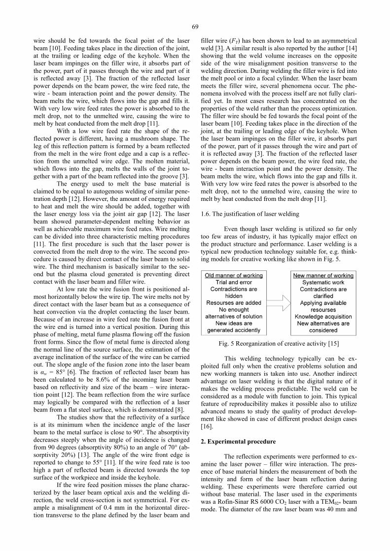
too few areas of industry, it has typically major effect on the product structure and performance. Laser welding is a typical new production technology suitable for, e.g. think-ing models for creative working like shown in Fig. 5.
Fig. 5 Reorganization of creative activity [15] This welding technology typically can be ex-ploited full only when the creative problems solution and new working manners is taken into use. Another indirect advantage on laser welding is that the digital nature of it makes the welding process predictable. The weld can be considered as a module with function to join. This typical feature of reproducibility makes it possible also to utilize advanced means to study the quality of product develop-ment like showed in case of different product design cases [16]. 2. Experimental procedure
The reflection experiments were performed to ex-amine the laser power – filler wire interaction. The pres-ence of base material hinders the measurement of both the intensity and form of the laser beam reflection during welding. These experiments were therefore carried out without base material. The laser used in the experiments was a Rofin-Sinar RS 6000 CO2 laser with a TEM02* beam mode. The diameter of the raw laser beam was 40 mm and
70
the diameter of focal point 0.26 mm. The process parameters used, laser beam set up
and shielding gas arrangement, were those typically used to weld steel thickness in the range 3 - 6 mm, with filler wire for bridging a butt joint air-gap. The shielding gas was introduced through a nozzle coaxial with the laser beam. Shielding was performed with helium gas, with 20 l/min flow rate. Initial trials concerned the investigation of the reflection angle by placing a cylinder of heat sensitive paper around the beam - wire interaction point coaxial with the incoming laser beam. A short laser energy pulse (1 W/10 ms) was then focused on the surface of the filler wire and the angle of reflection detected by the heat sensi-tive paper. The filler wire was a commercially available G3Si copper coated GMAW wire, of diameter 0.8 mm, suitable for welding of low alloyed steel.
The literature review and earlier experiments had shown that the direction of reflected laser beam is typically aimed symmetrically in a plane defined by laser beam op-tical axis and filler wire central axis. The reflection is fol-lowing this plane and the beam is reflected to opposite side of the beam in comparison to wire feeding. Based on this information the position of measurement means of reflec-tion was defined.
2.1. Reflections during laser welding
The welding experiments were performed to es-
tablish suitable welding parameters for laser welding with filler wire. A schematic illustration of the experimental set-up is shown in Fig. 6. The beam was focused using a para-bolic off-axis focusing mirror of 150 mm focal length. Shielding gas was introduced coaxially with the vertical laser beam and plasma control gas at a 45° angle to the laser beam, directed to the beam-wire interaction point.
Wire
Welding direction
Laser beam
Body andheat paper
Welding direction
Body andheat paperWire
Laser beam
a b
Fig. 6 The arrangements of welding experiments the reflec-tion definition experiments are also shown as the body and heat paper: a - is case of trailing feed and b -case of leading feed
The nozzle diameter was 5 mm. The laser beam
was focused on the surface of the workpiece, in the middle of the joint, and the filler wire was fed to the interaction point of the laser beam and the workpiece (Fig. 6).
The parameters used were selected such that the welding and acceptable weld quality was obviously reached. The weld quality was evaluated according to valid laser weld quality standard EN ISO 13919-1, where laser weld has quality levels B, C, D and rejected quality [17].
A set of simulating experiments of reflected power measurements were performed. The simulation was required since the measurement was impossible due to dimensions of the measuring equipment.
Table 1 The parameters used in experiments
Laser power
Feed dir.
Feed angle
Wire dia.
Focal pos.
Feed pos.
Focal length
Wel-ding speed
Wire feed rate
kW o mm mm mm mm m/min m/min1 5 LF 60 0.8 -2 -2 300 0.60 7.2
2 5 LF 60 1 0 0 150 0.75 6 3 5 LF 60 0.8 2 2 150 0.90 10.7 4 5 LF 45 0.8 0 0 150 0.90 10.7 5 5 LF 45 1 2 2 300 0.60 4.7 6 5 LF 45 0.8 -2 -2 150 0.75 9.2 7 5 LF 30 1 -2 2 150 0.90 7.1 8 5 LF 30 0.8 0 -2 150 0.60 7.2 9 5 LF 30 0.8 2 0 300 0.75 9.2
10 5 TF 60 0.8 2 0 150 0.60 7.2 11 5 TF 60 0.8 -2 2 150 0.75 9.2 12 5 TF 60 1 0 -2 300 0.90 7.1 13 5 TF 45 1 2 -2 150 0.75 6 14 5 TF 45 0.8 -2 0 300 0.90 10.7 15 5 TF 45 0.8 0 2 150 0.60 7.2 16 5 TF 30 0.8 0 2 300 0.75 9.2 17 5 TF 30 0.8 2 -2 150 0.90 10.7 18 5 TF 30 1 -2 0 150 0.60 4.7
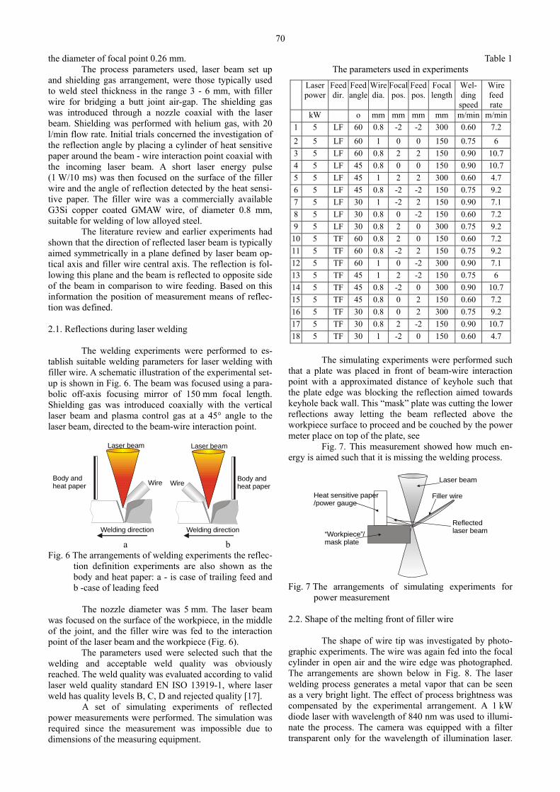
The simulating experiments were performed such
that a plate was placed in front of beam-wire interaction point with a approximated distance of keyhole such that the plate edge was blocking the reflection aimed towards keyhole back wall. This “mask” plate was cutting the lower reflections away letting the beam reflected above the workpiece surface to proceed and be couched by the power meter place on top of the plate, see
Fig. 7. This measurement showed how much en-ergy is aimed such that it is missing the welding process.
Reflected laser beam
Laser beam
“Workpiece”/mask plate
Heat sensitive paper/power gauge
Filler wire
Fig. 7 The arrangements of simulating experiments for power measurement
2.2. Shape of the melting front of filler wire
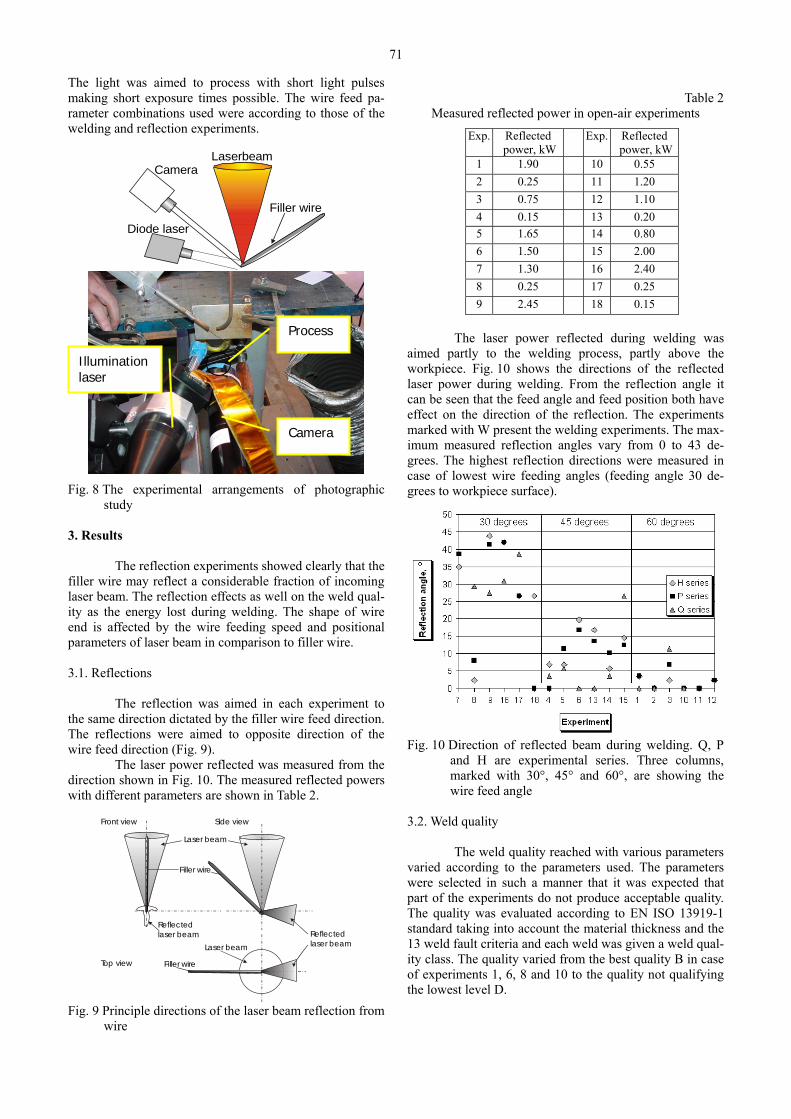
The shape of wire tip was investigated by photo-
graphic experiments. The wire was again fed into the focal cylinder in open air and the wire edge was photographed. The arrangements are shown below in Fig. 8. The laser welding process generates a metal vapor that can be seen as a very bright light. The effect of process brightness was compensated by the experimental arrangement. A 1 kW diode laser with wavelength of 840 nm was used to illumi-nate the process. The camera was equipped with a filter transparent only for the wavelength of illumination laser.
71
The light was aimed to process with short light pulses making short exposure times possible. The wire feed pa-rameter combinations used were according to those of the welding and reflection experiments.
Laserbeam
Filler wire
Camera
Diode laser
Fig. 8 The experimental arrangements of photographic study
3. Results
The reflection experiments showed clearly that the filler wire may reflect a considerable fraction of incoming laser beam. The reflection effects as well on the weld qual-ity as the energy lost during welding. The shape of wire end is affected by the wire feeding speed and positional parameters of laser beam in comparison to filler wire.
3.1. Reflections
The reflection was aimed in each experiment to
the same direction dictated by the filler wire feed direction. The reflections were aimed to opposite direction of the wire feed direction (Fig. 9).
The laser power reflected was measured from the direction shown in Fig. 10. The measured reflected powers with different parameters are shown in Table 2.
Reflected laser beam
Laser beam
Filler wire
Laser beam
Reflected laser beam
Filler wire
Front view
Top view
Side view
Fig. 9 Principle directions of the laser beam reflection from
wire
Table 2
Measured reflected power in open-air experiments
Exp.
Reflected power, kW
Exp.
Reflected power, kW
1 1.90 10 0.55 2 0.25 11 1.20 3 0.75 12 1.10 4 0.15 13 0.20 5 1.65 14 0.80 6 1.50 15 2.00 7 1.30 16 2.40 8 0.25 17 0.25 9 2.45 18 0.15
The laser power reflected during welding was
aimed partly to the welding process, partly above the workpiece. Fig. 10 shows the directions of the reflected laser power during welding. From the reflection angle it can be seen that the feed angle and feed position both have effect on the direction of the reflection. The experiments marked with W present the welding experiments. The max-imum measured reflection angles vary from 0 to 43 de-grees. The highest reflection directions were measured in case of lowest wire feeding angles (feeding angle 30 de-grees to workpiece surface).
Fig. 10 Direction of reflected beam during welding. Q, P
and H are experimental series. Three columns, marked with 30°, 45° and 60°, are showing the wire feed angle
3.2. Weld quality
The weld quality reached with various parameters
varied according to the parameters used. The parameters were selected in such a manner that it was expected that part of the experiments do not produce acceptable quality. The quality was evaluated according to EN ISO 13919-1 standard taking into account the material thickness and the 13 weld fault criteria and each weld was given a weld qual-ity class. The quality varied from the best quality B in case of experiments 1, 6, 8 and 10 to the quality not qualifying the lowest level D.
Illumination laser
Camera
Process
72
Table 3 The quality levels reached in experiments
Exp.
Weld qual-ity
Exp.
Weld quality
1 B 10 B 2 D 11 F 3 F 12 F 4 F 13 C 5 - 14 F 6 B 15 F 7 - 16 - 8 B 17 F 9 F 18 C
The achieved quality class B, C, D is shown with
equivalent letter. Letter F means the part failed the quality testing and – means that the part was not possible to evalu-ate.
The cross-section examples of different quality levels are shown below in Fig. 11.
a
b
Fig. 11 Examples of weld cross-sections reaching different quality levels: a - weld class B in case of experi-ment 1; b - failed weld in case of experiment 2
3.3. Wire melting
The photography of the phenomena during melt-
ing of the wire in open air resulted acceptable quality pho-tographs. The wire, droplet and wire beam interaction zone are all clearly visible. The disturbing plasma cloud can be seen in some photographs as a pale mist escaping from the interaction zone to the direction about parallel to the mol-ten surface.
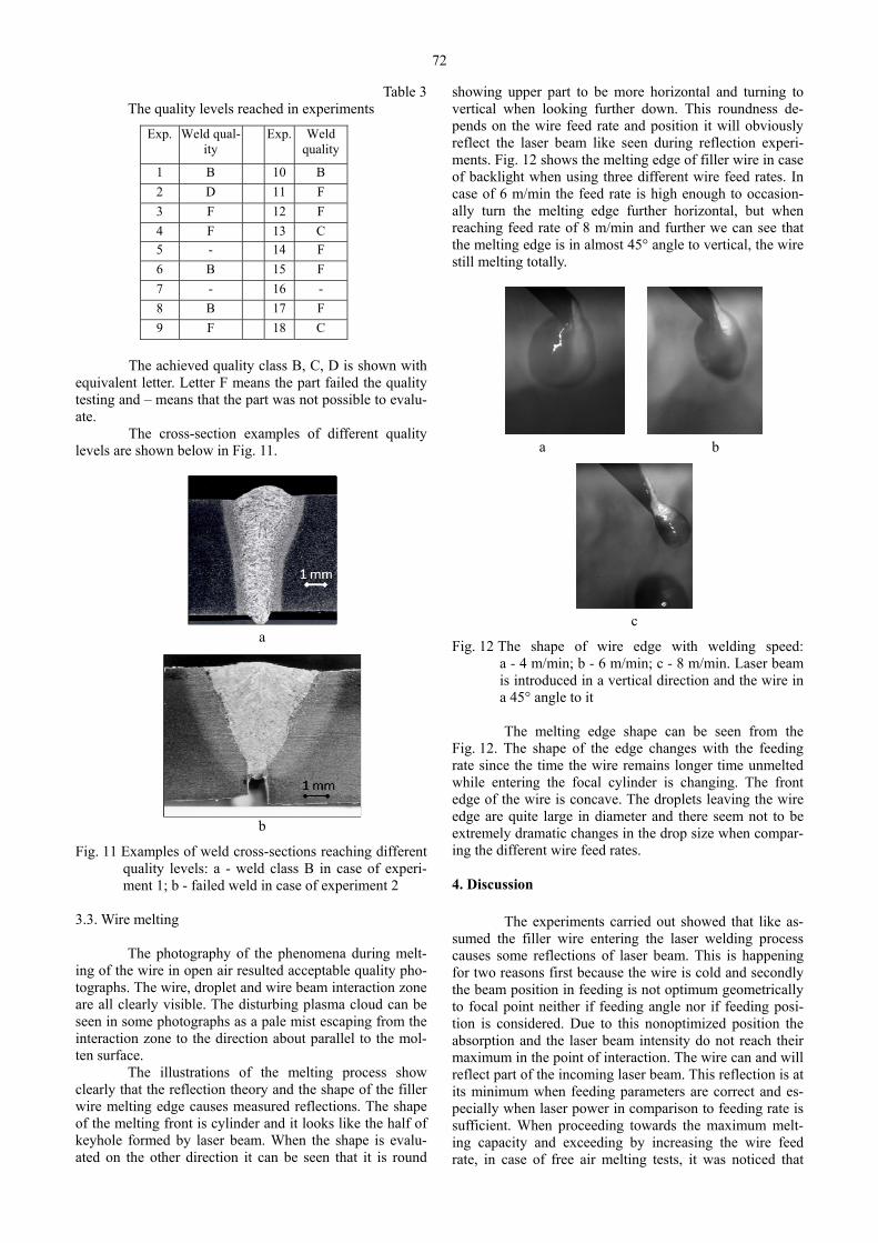
The illustrations of the melting process show clearly that the reflection theory and the shape of the filler wire melting edge causes measured reflections. The shape of the melting front is cylinder and it looks like the half of keyhole formed by laser beam. When the shape is evalu-ated on the other direction it can be seen that it is round
showing upper part to be more horizontal and turning to vertical when looking further down. This roundness de-pends on the wire feed rate and position it will obviously reflect the laser beam like seen during reflection experi-ments. Fig. 12 shows the melting edge of filler wire in case of backlight when using three different wire feed rates. In case of 6 m/min the feed rate is high enough to occasion-ally turn the melting edge further horizontal, but when reaching feed rate of 8 m/min and further we can see that the melting edge is in almost 45° angle to vertical, the wire still melting totally.
a b
c
Fig. 12 The shape of wire edge with welding speed: a - 4 m/min; b - 6 m/min; c - 8 m/min. Laser beam is introduced in a vertical direction and the wire in a 45° angle to it
The melting edge shape can be seen from the
Fig. 12. The shape of the edge changes with the feeding rate since the time the wire remains longer time unmelted while entering the focal cylinder is changing. The front edge of the wire is concave. The droplets leaving the wire edge are quite large in diameter and there seem not to be extremely dramatic changes in the drop size when compar-ing the different wire feed rates.
4. Discussion
The experiments carried out showed that like as-sumed the filler wire entering the laser welding process causes some reflections of laser beam. This is happening for two reasons first because the wire is cold and secondly the beam position in feeding is not optimum geometrically to focal point neither if feeding angle nor if feeding posi-tion is considered. Due to this nonoptimized position the absorption and the laser beam intensity do not reach their maximum in the point of interaction. The wire can and will reflect part of the incoming laser beam. This reflection is at its minimum when feeding parameters are correct and es-pecially when laser power in comparison to feeding rate is sufficient. When proceeding towards the maximum melt-ing capacity and exceeding by increasing the wire feed rate, in case of free air melting tests, it was noticed that
73
total melting of the wire was possible only to some extent and after that the filler wire does not anymore melt but is only heated. In this case the solid wire hits the laser beam in non-optimum positions and the fraction of reflected beam almost reached 50% (2.45 kW of the laser power of 5 kW was reflected in worst case) of incoming laser power. Since the reflective surface is partly formed by the solid wire, the direction of this reflected beam is aimed above the workpiece during welding if the wire is fed in a low angle compared to the workpiece surface. The direction of this reflection is surprisingly accurate and aimed by the reflecting surface angle to the laser beam. The most risky, low feed angle must usually be avoided in practice because the arrangement requires lot of room in front of welding nozzle, which is not typically available during practical welding. In practical applications this low feeding angle is not used due to the dimensional problems of feeding equipment and complexity increase in case of 2-3 D appli-cations.
The photographs of wire end in melting show that the assumed shape of the wire end is equivalent with sur-prisingly high reliability to the assumptions of wire edge quality gained by the reflection experiments. The photo-graphs showed also that the high wire feed rate will that block the keyhole. As is shown the higher the wire feed rate the deeper in enters the focal point prior melting. When the critical speed is exceeded (5 kW laser power and 0.8 mm wire diameter the critical speed is 8 m/min) the wire will pass the focal point, still melting but generating large molten droplets. The photographs of the molten drop-let show also the fact the molten material moves below the wire – away from the laser beam. This caused by the pres-sure of the plasma cloud that introduces forces exceeding the force of gravity and the feeding movement.
There is a lower risk of weld imperfections when the energy input is increased even though the feeding posi-tion parameters are not optimized. In practice this can be done by lowering the welding speed from the absolute maximum. The higher energy input generates a larger cloud of metal vapor cloud and larger weld pool. In this case the power intensity required for melting and vaporiz-ing the material can be reached. The formed large plume of metal vapor will melt the wire even if it is fed inaccurately; the plume also absorbs the laser beam reflected from the wire. If wire feed angle is steep, i.e. more than 45°, most of the reflection is directed into the keyhole. Steep feeding angle is on the other hand risky if the wire does not hit the joint.
a b
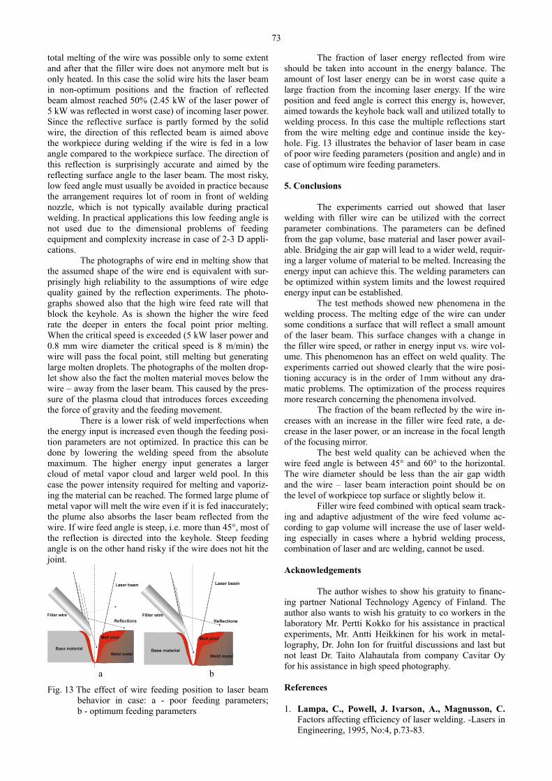
Fig. 13 The effect of wire feeding position to laser beam behavior in case: a - poor feeding parameters; b - optimum feeding parameters
The fraction of laser energy reflected from wire should be taken into account in the energy balance. The amount of lost laser energy can be in worst case quite a large fraction from the incoming laser energy. If the wire position and feed angle is correct this energy is, however, aimed towards the keyhole back wall and utilized totally to welding process. In this case the multiple reflections start from the wire melting edge and continue inside the key-hole. Fig. 13 illustrates the behavior of laser beam in case of poor wire feeding parameters (position and angle) and in case of optimum wire feeding parameters.
5. Conclusions
The experiments carried out showed that laser welding with filler wire can be utilized with the correct parameter combinations. The parameters can be defined from the gap volume, base material and laser power avail-able. Bridging the air gap will lead to a wider weld, requir-ing a larger volume of material to be melted. Increasing the energy input can achieve this. The welding parameters can be optimized within system limits and the lowest required energy input can be established.
The test methods showed new phenomena in the welding process. The melting edge of the wire can under some conditions a surface that will reflect a small amount of the laser beam. This surface changes with a change in the filler wire speed, or rather in energy input vs. wire vol-ume. This phenomenon has an effect on weld quality. The experiments carried out showed clearly that the wire posi-tioning accuracy is in the order of 1mm without any dra-matic problems. The optimization of the process requires more research concerning the phenomena involved.
The fraction of the beam reflected by the wire in-creases with an increase in the filler wire feed rate, a de-crease in the laser power, or an increase in the focal length of the focusing mirror.
The best weld quality can be achieved when the wire feed angle is between 45° and 60° to the horizontal. The wire diameter should be less than the air gap width and the wire – laser beam interaction point should be on the level of workpiece top surface or slightly below it.
Filler wire feed combined with optical seam track-ing and adaptive adjustment of the wire feed volume ac-cording to gap volume will increase the use of laser weld-ing especially in cases where a hybrid welding process, combination of laser and arc welding, cannot be used.
Acknowledgements
The author wishes to show his gratuity to financ-ing partner National Technology Agency of Finland. The author also wants to wish his gratuity to co workers in the laboratory Mr. Pertti Kokko for his assistance in practical experiments, Mr. Antti Heikkinen for his work in metal-lography, Dr. John Ion for fruitful discussions and last but not least Dr. Taito Alahautala from company Cavitar Oy for his assistance in high speed photography. References 1. Lampa, C., Powell, J. Ivarson, A., Magnusson, C.
Factors affecting efficiency of laser welding. -Lasers in Engineering, 1995, No:4, p.73-83.
74
2. Lampa, C. Laser Welding; Energy redistribution and weld geometry. Doctoral Thesis. Lulea University of Technology. 1997:33. ISSN:1402-1544. ISRN: LTU-DT—1997:33—SE.-137p.
3. Arata, Y., Maruo, H., Miyamoto, I., Nishio, R. High power CO2 laser welding of thick plate. multipass welding with filler wire. -Trans. Jwri 15, (2), 1986, p.199-206.
4. Watson, M.N., Dawes, C.J. Laser welding of structural steel with wire feed. -The Welding Institute research report 264/1985, The Welding Institute, Cambridge, March 1985. -36p.
5. Nielsen, S.E., Hansen, L.E., Kristensen, J.K. High power laser welding of C/Mn steel. -The effects of using different filler materials and plasma control gases. Proc. 5th int. Conf. on Welding and Melting by Electron and Laser Beams, 14-18 June, 1993, La Baule, France, Organized by Institut de Soudure and TWI, vol.1, p.203-210.
6. Dilthey, U., Hendricks, M., Huwer, A., Jacobskötter, L., Scneegans, J. Adaptive Drahtzuführung für das Laserstrahlschweissen bei variable Fügespaltweiten. Proc. Int. Conf.Beam Technology, Karlsruhe, Germa-ny, 13.-14.3.1991, DVS-Berichte Band 135, p.71-74.
7. Bagger, C. Investigations in On-Line Process Control of the Laser Welding Process. Doctoral thesis. -Technical University of Danmark, 1991, APP.91-02/PI.91.1-A.-280p.
8. Cleemann, L. Schweissen mit CO2-Hochleistungsla-sern. -Düsseldorf: Technologie Aktuell 4, VDI-Verlag GmbH, 1987.-256p.
9. Hügel, H., Dausinger, F. Interaction Phenomena and Energy Coupling in Laser Treatment Processes. -Process Fundamentals par 2/3. Euro Laser Academy, 1996.-57p.
10. Panten, M., Schneegans, J., Hendricks, M., Huwer, A., Jacobskötter, L. Laser Welding with Filler Wire. IIW-DOC. IV-545-90, 1990.-17p.
11. Dilthey, U., Schneegans, J. Studies in laser beam welding with filler wire addition of unalloyed and low alloyed steels. Schweissen und Schneiden 46, 1994, Heft 3, p.119-123.
12. Carlson, K.W., Gregson, V.G. A parametric study of narrow gap laser welding. -Materials Processing Confe-rence ICALEO'86, Arlington, Virginia, USA, 10.-13.11.1986, Laser Institute of America, p.211-222.
13. Beyer, E., Behler, K., Herziger, G. Influence of laser beam polarization in welding. -Proc. 5th Int. Conf. Lasers in Manufacturing, September 1988, p.233-240.
14. Salminen, A.S. Laser Welding with Filler Wire. Licenciate thesis. -Lappeenranta University of Technology. Lappeenranta 1992.-103p. (in Finnish).
15. Povilionis, A., Bargelis, A. Structural optimization in product design process. -Mechanika. -Kaunas: Technologija, 2010, Nr.1(81), p.66-70.
16. Čikotienė, D., Bargelis, A. Research of quality impact to the product design properties and characteristics. -Mechanika. -Kaunas: Technologija, 2009, Nr.5(79), p.63-67.
17. EN ISO 13919-1: Welding – Electron and laser-beam welded joints – Guidance on quality levels for imperfection – Part 1: Steel.-9p.
A. Salminen UŽPILDANČIOS VIELOS SĄVEIKA SU LAZERIO SPINDULIU SUVIRINANT MAŽAI LEGIRUOTĄ PLIENĄ R e z i u m ė
Lazerinis suvirinimas vis plačiau taikomas įvai-riose pramonės šakose. Suvirinimas naudojant užpildančią vielą dažnai vertinamas kaip įprastinis metodas. Šis darbas parodė, kad nustačius tam tikrus apribojimus užpildanti viela gali būti naudojama pramoniniam suvirinimui. Laze-rio spindulio atspindys nuo vielos paviršiaus gali būti dide-lis, tačiau jį galima kontroliuoti pagal normalius atspindžio dėsnius. Suvirinimo procese gali būti panaudota ir dalis spindulio atspindžio nuo vielos paviršiaus.
A. Salminen THE FILLER WIRE - LASER BEAM INTERACTION DURING LASER WELDING WITH LOW ALLOYED STEEL FILLER WIRE S u m m a r y
Laser welding is gaining new applications in vari-ous industries. Often the use of filler wire is not considered due to reputation of complicity. This study has, however gained almost no interest of research groups after millen-nium. The study showed that when certain rules are fol-lowed the filler wire feeding can be used and applied to industrial applications. The reflection of the laser beam from wire surface can be considerable, but I can be con-trolled due to its behavior according to the normal reflec-tion laws. Even the fraction of beam reflecting from the wire surface can be utilized to the process. А. Салминен ВЗАИМОДЕЙСТВИЕ ПРИСАДОЧНОЙ ПРОВОЛОКИ С ЛАЗЕРНЫМ ЛУЧОМ ПРИ ЛАЗЕРНОЙ СВАРКЕ НИЗКО ЛЕГИРОВАННОЙ СТАЛИ Р е з ю м е
Использование лазерной сварки в промыш-ленности расширяется. Применение присадочной про-волоки часто оценивается как обычный метод. Данное исследование показало, что при введении некоторых ограничений использование присадочного материала может быть применено в промышленности. Отражение лазерного луча от поверхности проволоки может быть значительным, но его можно контролировать по нор-мальным законам отражения. В процессе сварки может быть использовано даже часть отраженного луча от поверхности проволоки.
Received February 23, 2010 Accepted June 21, 2010