Embed Size (px)
Citation preview
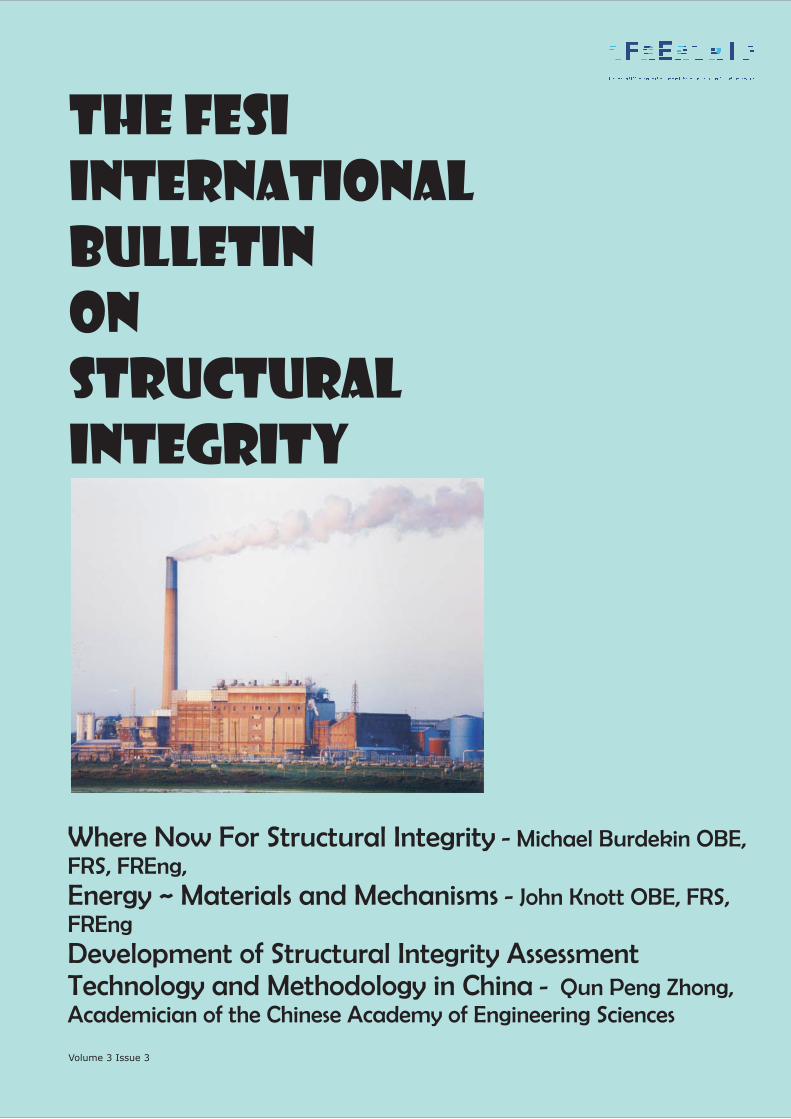
The FESI
International
BULLETIN
On
Structural
Integrity
Where Now For Structural Integrity - Michael Burdekin OBE,
FRS, FREng,
Energy ~ Materials and Mechanisms - John Knott OBE, FRS,
FREng
Development of Structural Integrity Assessment
Technology and Methodology in China - Qun Peng Zhong,
Academician of the Chinese Academy of Engineering Sciences
Volume 3 Issue 3
Contents
Who’s Who in FESI
Where now for StructuralIntegrity
ESIA9 Conference Report
FESI Seminar Reports
Energy - Materials andMechansms
Plant Ageing Guide
FESI New Events -including ESIA10
Development of SIATechnology andMethodology in China
Forthcoming WorldwideEvents
3 -
4 -
Prof Mike Burdekin
6 -Prof Su Jun Wu
8 -
12 -
Prof John Knott
19 -Dr Philippa Moore
22 -
23 -
Prof Qun Peng Zhong
34 -
22 - Membership andSponsorship
EDITORIALThis is the third issue of the FESI International Bulletin on Structural
Integrity. The Bulletin is produced annually as part of FESI's role to
provide a forum for exchange of information and experience in structural
integrity across industry sectors. This issue contains a number of articles,
including an overview on the subject by Professor Michael Burdekin, an
HSE sponsored Guide to Plant Ageing authored by Dr Philippa Moore of
TWI, and keynote papers by the co-chairs of the ESIA9 Conference,
Professor John Knott and Professor Zhong. This Conference, held in
Beijing in October 2007, was a major new venture for FESI in partnership
with Beijing University of Aeronautics and Astronautics, and was
supported by The Royal Academy of Engineering and The Chinese
Academy of Engineering. Professor Su Jun Wu has provided an overview
of the Conference.
In 2008, FESI organised three successful Professional Development
Workshops; on Hydrogen Assisted Cracking (NPL), on Quasi-brittle
Materials (Royal Academy of Engineering), and on Developments in
Engineering Structural Integrity (University of Manchester). In this issue,
there is a report on the RAEng meeting and on the panel discussion at the
Manchester meeting. In addition, FESI has co-sponsored several events
organised by other institutions and societies.
During the year we have welcomed two new corporate sponsors: Fraser-
Nash Consultancy and The University of Sheffield. In addition, The Health
and Safety Executive has become a named Supporter. Four new members
of the FESI Council have also been appointed: Dr Phil Horrocks (ESR
Technology), Professor John Yates (U Sheffield), Andy Holt (HSE), Keith
Wright (Rolls-Royce).
EMAS Publishing, the publishing arm of FESI, has had a successful year
with the publication of John Draper's book “Modern Metal Fatigue
Analysis”. Other books are scheduled for publication in 2009 and these
will be detailed on our publishing website .
All readers of the Bulletin are encouraged to utilise the network which is
FESI and any questions, comments, and other contributions are always
welcome.
Brian Tomkins
www.emas.co.uk
Who’s FESI?Over the past 10 years, a UK group of interested industry parties hasorganised a successful series of biennial international conferences, held onthe subject of ESI, which has sought to examine the status of the technologyand its effectiveness in application. More recently an associated programmeof teaching seminars has developed, using senior expert academic staff, topropagate good practice and awareness in areas such as risk based tools andmethods, and the quantification of failure. This collective experience hasbeen brought together under the UK Forum for
(FESI).
The aim of FESI is to provide opportunity to facilitate the effectivedevelopment and implementation of ESI technology across industry sectors.We believe that this will be achieved through the following means:
The organisation of teaching seminars on developments in ESItechnology and its application.The organisation of one day topical discussion seminars oninterdisciplinary and/or cross industry sector issues in ESI.The organisation of specific industry
.The organisation, as appropriate, of international Conferences in theUK on Engineering Structural Integrity Assessment concerned withthe dissemination of ESI technology and its application acrossindustry sectors.Liaison with other bodies involved in significant ESI R&D andapplications programmes (e.g. EPSRC, European Structural IntegritySociety (ESIS), EU/JRC Networks, International Institute of Welding).The organisation, jointly with collaborators, of similar nationalconferences/seminars in the UK and other countries.
Through these activities, the Forum seeks to encourage technology transferacross industry sectors and the development of technologies which willsupport the safe and cost-effective design and operation of majorengineering plant, structures and components. Its activities will cover arange of industries including aerospace, petrochemical, oil and gas, powergeneration, automotive, transport and construction. Technologyintegration includes inspection, monitoring, diagnosis, analysis, materials,IT and assessment methods.
Engineering StructuralIntegrity
discussions/meetings/seminarson ESI, on request
�
�
�
�
�
�
FESI International Bulletin of Structural Integrity
Editorial Team
John EdwardsBrian TomkinsAndrew SherryMike BurdekinPeter Flewitt
International membersIain Le May - CanadaRoy Penny - South Africa
© UK Forum for EngineeringStructural Integrity (FESI)
ISSN 1744-6813
Information published in the FESIInternational Bulletin on Structural Integritydoes not necessarily represent the views ofthe publisher. Whilst effort has been made toensure that the information is accurate thepublisher makes no representation orwarranty, express or implied, as to theaccuracy, completeness or correctness ofsuch in format ion . I t accepts noresponsibility whatsoever for any loss,damage or other liability arising from anyuse of this publication or the informationwhich it contains.
Contact:Poul GosneyChief ExecutiveFESI - UK Forum for EngineeringStructural IntegrityWhittle HouseBirchwood ParkWarringtonWA3 6FWT: +44 (0)1925 843429F: +44 (0)1925 843498E: [email protected]: www.fesi.org.uk
2

FESI International Bulletin of Structural Integrity
Who’s Who on the FESI Council
John Edwards MBE
Professor Peter Flewitt FREng
Dr Brian Tomkins FREng
Professor Ferri Aliabadi
Philip Heyes
Dr Phil Horrocks
Professor John Knott OBE, FRS, FREng
Dr Iain Le May
Dr Henryk Pisarski
John Sharples
Professor Andrew Sherry
Professor David Smith
Professor Rod Smith FREng
Dr Alan Turnbull
Professor Gordon Williams FRS FREng
There are four new members of the Council: Professor John Yates of the University of Sheffield, KeithWright from Rolls-Royce plc who replaces John Howson, Dr Phil Horrocks from ESR Technology andAndrew Holt from the HSE (NII).
is a consultant with many years experience in testing technology, and was a leadassessor National Accreditation, Measurement and Sampling (NAMAS) in mechanical testing.
is Consultant Professor within Magnox North Ltd. He has worked on arange of structural integrity topics in the power generation industry amd undertakes research intofracture and locked-in stresses at Bristol University.
is a consultant and an expert in engineering plant integrity and safety.
holds the Chair of Aerostructures and is the Head of Aerostruture Section atImperial College, London. His particular expertise is in the areas of computational structuralmechanics, fracture mechanics and fatigue, materials modelling, and boundary and finite elementmethods.
is Head of the Engineering Control Group at the Health and Safety Laboratory.
is the General Manager of ESR Technology's Asset Integrity Group. The group'sactivities encompass all aspects of integrity management in design and operation of assetspredominantly in the Oil & Gas and Chemicals industries delivering projects ranging from high levelintegrity focused management consultancy to detailed assessment of defects and inspectiontechnology performance.
is the Feeney Professor of Metallurgy and Materials at theUniversity of Birmingham with a particular interest in fracture and crack arrest.
is President of Metallurgical Consulting Services Ltd., Canada. He is a renownedexpert witness in Canada and USA in the areas of materials and materials science, and the analysis offailures.
is Technology Manager - Fracture in the Structural Integrity Technology Group atTWI, Cambridge, UK, concerned with the application of fracture mechanics testing and flawassessment procedures (Engineering Critical Assessments) to welds.
is responsible for a team of fracture mechanics specialists working on variousresearch and development projects including the R6 Development Programme within SercoAssurance’s Structural Integrity Assessments Department.
is the Director of the Material Performance Centre at the University ofManchester.
is Head of the Solid Mechanics Research Group in Bristol University’sDepartment of Mechanical Engineering with particular interests in fracture of materials and locked-instresses in engineering components. He is also a non-Executive Director of VEQTER Ltd.
heads the Future Railway Research Centre at Imperial College, London.He is an authority on fracture and fatigue particularly in the Rail industry.
is a Senior Consulting Engineer at the National Physical Laboratory, specialising incorrosion and fatigue.
is a Senior Research Investigator in the Department ofMechanical Engineering at Imperial College. He is a world expert on polymers.
is an Inspector of Nuclear Installations workingealth and afety xecutive.
Keith Wright
Professor John Yates FIMechE, CE
Andrew Holt
is currently a Structural Integrity Specialist in the Nuclear Sector within Rolls-Royce andis the Structural Integrity Strategy Owner for the Naval Nuclear Research & Technology work. Keithhas recently become an ASME committee member of the Design Analysis and Fatigue Strengthsubgroups.
is Head of Mechanical Engineering Department at the Universityof Sheffield. He is Director of the White Rose Centre for Excellence for the Teaching and Learning ofEnterprise, a Co-Director of IMMPETUS (Institute for Microstructural and Mechanical ProcessEngineering: The University of Sheffield) and Editor in Chief of the Blackwell Science internationaljournal Fatigue and Fracture of Engineering Structures and Materials.
for the Nuclear InstallationsInspectorate of the H S E
3
FESI International Bulletin of Structural Integrity
WHAT DO WE MEAN BY STRUCTURAL INTEGRITY?
RECENT TOPICS BY OTHER STRUCTURALINTEGRITY COMMITTEES
TAGSI
It is necessary firstly to be clear on what we mean by'Structural Integrity'. I take as a working definition:“The ability of a structure or component to performits required service duty safely for the requireddesign life, taking account of all reasonable loadingsand potential degradation mechanisms to which itmay be subjected.”Thus the key requirements of ensuring structuralintegrity are(1) a satisfactory basic design(2) use of suitable materials(3) satisfactory manufacturing and fabrication
procedures(4) control of operational conditions in service(5) periodic inspections in service to check
that no unexpected and unacceptabledegradation is occurring.
Many of these requirements are encapsulated indesign codes for specific applications, based onprevious experience and established good practice.These considerations are almost invariably based onan assumed 'perfect structure or component',perhaps with some arbitrary allowance fortolerances in fabrication.When it comes to consideration of the effects ofimperfect fabrication or degradation in service, it isnecessary to have a detailed understanding of thepotential mechanisms of failure. Thus it isnecessary to be able to consider the effects ofphysical defects of different types and themechanisms by which they may grow, as well aschanges in material properties that may occur inservice. Some mechanisms of failure are controlledby crack tip stress fields or conditions whilst othersare controlled by average stresses on the net crosssection. This is where the experts in fracturemechanics play an important role. However in anystructural integrity assessments it is essential thatexpertise is available in stress analysis, materialsbehaviour, non-destructive testing, failuremechanisms as well as overall design and serviceexperience of the component or structure ofconcern. This will often require a team of differentindividuals to be assembled. Regrettably there aresome occasions where erroneous conclusions arereached by an inexperienced assessor based on textbook understanding!
TAGSI stands for the Technical Advisory TechnicalGroup on Structural Integrity for the UK NuclearIndustry. The Main Committee consists of nineindependent members and representatives fromeach of the sponsors: British Energy Group plc,British Nuclear Group plc, Ministry of Defence andHSE (Nuclear Installations Inspectorate). TAGSIresponds to requests for authoritative guidance inresponse to specific questions raised by one or moreof the sponsors. These responses are usuallypublished in the open literature and form importantcontributions to statements of the currentunderstanding of particular problems.The following are examples of recent deliberationsby TAGSI:
Fracture Toughness of Steels in the TransitionRegion
Peer review of Impact Procedures
Current work
GTAC
The 'Master Curve' representation of the variationof fracture toughness with temperature from thereference temperature T , includes an adjustmentfor the thickness of the component beingconsidered, B, or more correctly for the length ofcrack front involved, as follows:
K (B)=K +[31+77exp(0.019(T-T ))- K ](B/25) [-ln(1-p)]
TAGSI was asked to advise whether there was anupper limit to the value of 'B' that needed to beconsidered and whether there was a lessconservative approach.TAGSI's view was that an upper limit to thethickness/crack front length correction wasreasonable. After examining a large data base ofexperimental evidence on A533B/A508 plate andforgings, TAGSI concluded that the Master Curveexpression fitted the data for median toughness upto 100 mm thickness and T ±500°C but that therewas no consistent effect of thickness on lowerbound fracture toughness.
TAGSI was asked to review the nuclear industries R3procedure for evaluating the likelihood of failure ofsteel and concrete structures under a range ofhazards including missiles, whipping pipes anddropped loads. TAGSI was supportive of andendorsed the procedure for carrying out simplifiedassessments but considered that moresophisticated methods may be required and werenow generally available for more complex problems.
TAGSI has been asked to comment on revisedproposals for calculation of creep damageinteractions with fatigue, in particular makingallowance for dwell periods in the overall history.The proposed new approach is a stress modifiedexhaustion of ductility method that allows forwhether the dwell period precedes or follows amaximum strain condition. It distinguishesbetween creep strains that occur under maintainedstress conditions and those that occur as arelaxation under fixed displacement conditions.TAGSI is also currently considering questionsrelated to characterisation of defects and theirinteraction, and to the applicability of structuralintegrity assessments to fully ductile applications toASME III.
GTAC stands for the Graphite Technical AdvisoryCommittee. It consists of nine independentmembers and responds to questions put by theNuclear Installations Inspectorate on a wide range ofissues concerned with graphite in Magnox and AGRreactors. Many of these questions have a structuralintegrity background and the committee involvesmembers with a range of backgrounds from materialaspects of graphite to stress analysis and structuralintegrity in steels and other materials. Theproblems in graphite are extremely complex andthere is much to be learnt from the behaviour ofthese different materials. Yet the general structuralintegrity community and the graphite communityseem to operate in independent arenas with little orno exchange of expertise except that achievedthrough the GTAC committee.
0
JC min 0 min
0
¼
¼
Where Now For Structural IntegrityProfessor Michael Burdekin OBE, FREngFRS,
4
TAGSI SYMPOSIA
2003 Design Margins and Safety FactorsRelated to Structural Integrity2005 Residual and Secondary Stresses inStructural Integrity Assessment Estimation,Measurement and Assessment2007
Structural Integrity under Dynamic Loading.
O N G O I N G S T R U C T U R A L I N T E G R I T YREQUIREMENTS
Materials Aspects
Dynamic Loading Aspects
Residual and Secondary Stresses
In alternate years, TAGSI organises technicalsymposia on structural integrity issues, theobjective of which is to provide a forum for debateand exchange of experience across differentindustries. The following symposia have been heldin recent years:
-.
-
., the Seminar was a joint one
between TAGSI and FESI on the topic
The following brief notes are examples of the way inwhich structural integrity methods can and arebeing used and of potential requirements forongoing research work.
Structural Integrity Assessment methods can beused to determine material property specificationrequirements for particular situations to suit designstress levels and standards of fabrication. This isparticularly the case where new materials areproposed or where existing materials are proposedfor new applications. An example of particularimportance is the use of higher strength materialswhere determination of fracture toughness andfatigue crack growth properties should be regardedas an essential pre-requisite to use for newapplications.
The whole field of dynamic loading is a fruitful onefor ongoing research into structural integrityassessment. Although there are improvements insimplified models and in the ability of properlyconstituted finite element analysis models torepresent effects of dynamic loading on structures,only limited work has been carried out on effects ofdefects and degradation on structures subject toimpact, earthquake or blast loading. Whilst thereare general principles that there will be a dynamicamplification of stresses dependent on the ratio ofthe rise time or frequency of the applied loading tothe natural frequency of the component, and theproperties of the material may be strain ratedependent, calculation of specific cases with abroad frequency spectrum may be very complex.Simplified methods to determine equivalentmaximum static loading conditions would beextremely helpful.
Effects of residual stresses have been well knownfor many years (at least since the middle of thetwentieth century). Yet there is still much researchbeing carried out to try to predict the effects ofresidual and secondary stresses. Some olderresearch workers may feel that this is an example ofthe wheel coming round again and youngerresearchers re-discovering things that have beenknown for years. However, this would be an unfaircriticism. What is happening, and what is needed,is that the rapid improvements in the ability of finiteelement programs and high powered computers tocalculate residual stress distributions and theireffects are providing much better accuracy inpredicting levels of residual stresses such thatprevious conservatisms may be reduced.
FESI International Bulletin of Structural Integrity
Fatigue and Environmental Crack Growth
Uncertainties, Risk and Safety Margins
Strain Based Methods of Assessment
Education! Education! Education!
There are still a number of failures that occur due tofatigue and/or environmental crack growth.Sometimes these are due to incorrect designassumptions. However, the interactions ofparticular materials with specific environments aresuch that this remains a rich field for ongoingtheoretical research into mechanisms andexperimental research into susceptibility andeffects on growth rates. The problem of predictingaccurately the effects of cyclic load interactions onrates of fatigue crack growth for specific loadspectra, with or without environmental effects,remains one that has not been solved satisfactorilybut is much needed.
The position will always remain that there arescatter in materials data and uncertainties inloading, stress analysis and assessment methods.It is therefore essential for structural integrityassessments to make appropriate allowance forsuch uncertainties without making excessivelyconservative assumptions that lead to unrealisticconclusions. The two approaches to this are eitherprobabilistic fracture mechanics treatments wherean acceptable probability of failure is linked to theconsequences through a risk assessment, or theuse of partial safety factors calibrated to achieve thesame effect. There is ongoing scope for furtherdevelopment of both of these approaches,particularly in relation to less well developed areasof structural integrity assessment such as responseto dynamic loading.
One of the disadvantages of the failure assessmentdiagram approach of the R6 methodology, alsoadopted in BS7910, is that the structure orcomponent is deemed to fail by plastic collapsewhen the net section stress reaches to yield or flowstrength of the material. There are situations whereloading may be displacement or strain controlledand there are also cases where contained yieldingmay occur at local stress concentration regions or inredundant parts of the structure. In such cases thestructure may have significant capacity beyond acondition where a simple local assessment deems itto be unacceptable. The original crack tip openingdisplacement 'design curve' from the 1970s relatedcrack tip driving conditions to applied strain and tothe size of crack present. A similar approach waspublished at the ESIA-5 conference in Cambridge in2000, linking the applied J integral value at thecrack tip to applied strain and defect size. Therehas been a recent addition to the R6 proceduredocument putting forward an approach for strainbased assessment but this appears to require aspecific finite element stress analysis to carry it out.I hope that the R6 panel will consider the alternativesimpler approach from the ESIA-5 conference paper.
One of the problems that I meet fairly regularly iswhere people who do not understand the principlesof fracture mechanics methods try to apply theBS7910 or R6 methods and get it wrong! There is noalternative but to ensure that there is an adequatesupply of 'Engineers' who have included in theireducation a proper appreciation and training instructural integrity assessment methods. In the2006 John Player Lecture to the Institution ofMechanical Engineers the author made the case forhaving at least one Masters course includingspecialist modules in structural integrity supportedby those industries with a strong dependence in thissubject area for safety or success of their business.I close by repeating this plea!
5
FESI International Bulletin of Structural Integrity
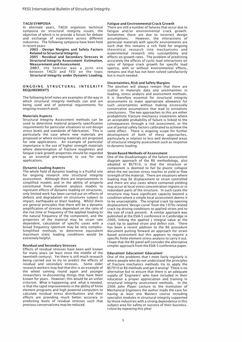
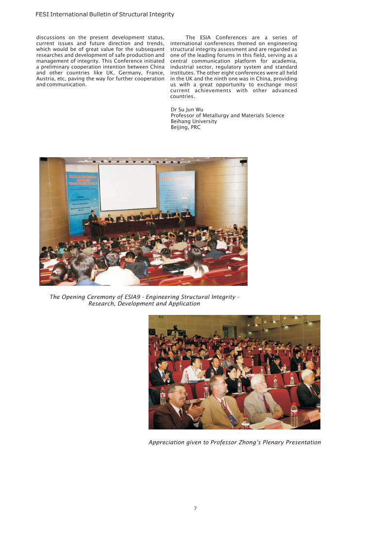
ESIA9 - 9 International Conference onEngineering Structural Integrity Assessment,hosted together by the Chinese Academy ofEngineering, the Royal Academy of Engineering,Beijing University of Aeronautics and Astronautics(BUAA) and the Forum of Engineering StructuralIntegrity (FESI), was held in the Conference Centre ofBUAA from October 15 to 19 , 2007. The vicepresident of BUAA, Professor Xu Huibin, presidedover the opening ceremony. The Academician of theChinese Academy of Engineering (CAE), Chairmanof the conference(China), ProfessorZhong Qunpeng,made the openingspeech, in which heh igh l i gh t ed thef u n c t i o n s a n dsignificance of theC o n f e r e n c e ,expressed his highexpectation for thes u c c e s s o f t h eConference.
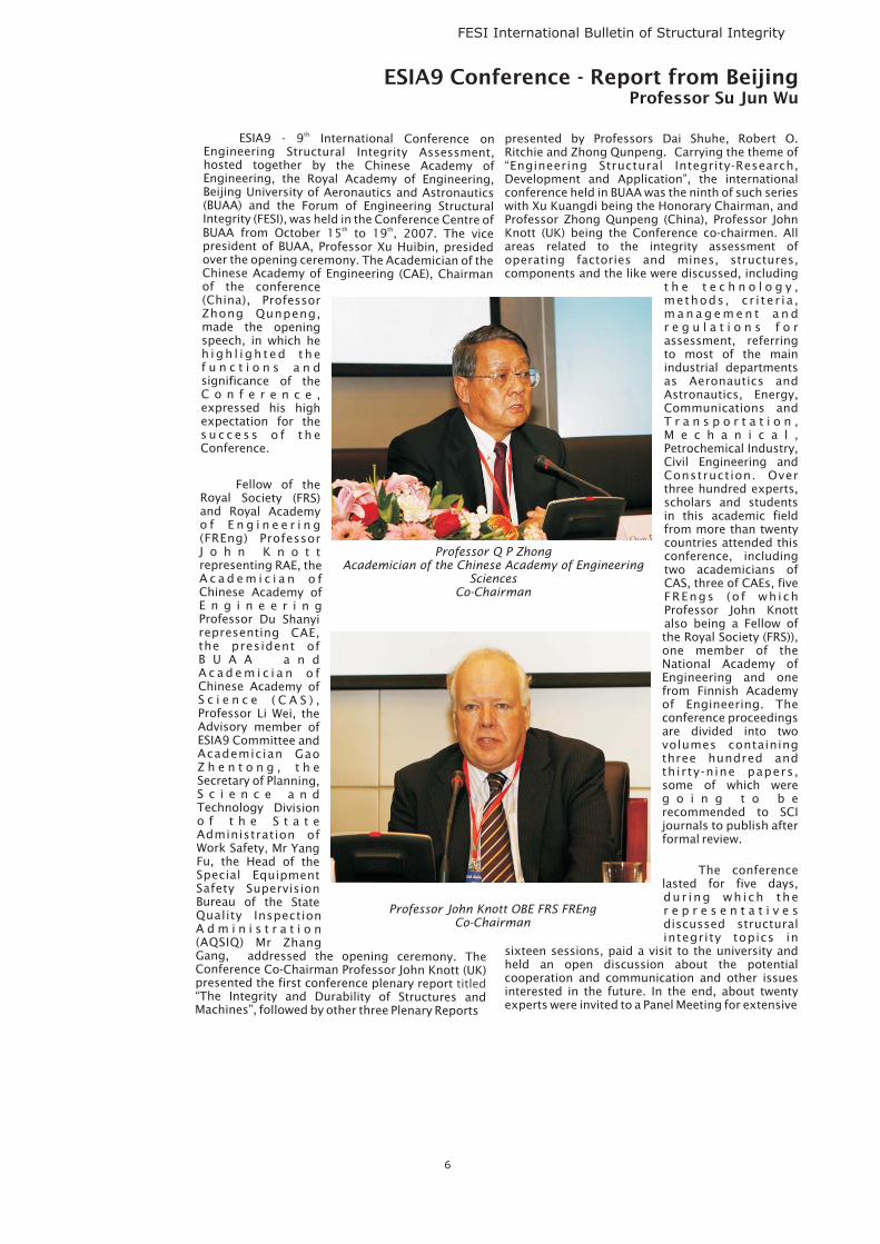
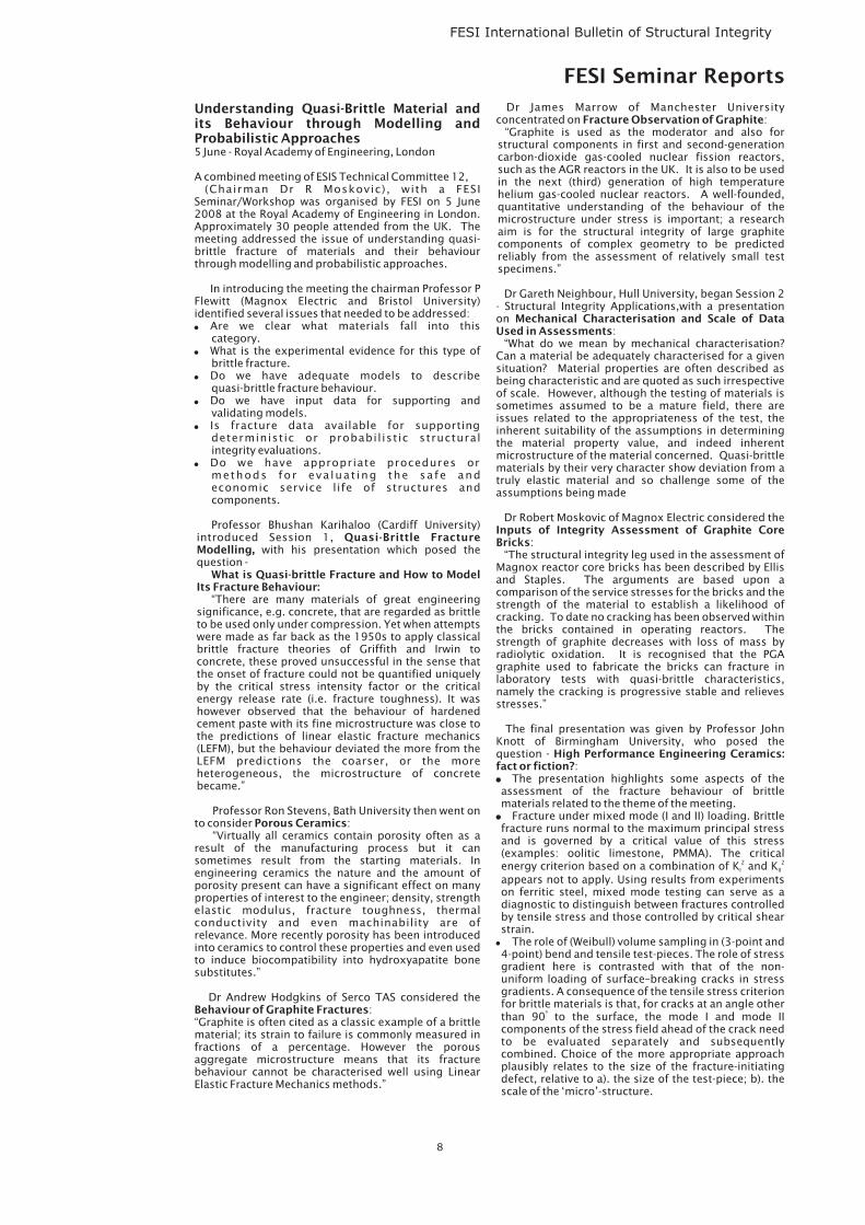
Fellow of theRoyal Society (FRS)and Royal Academyo f E n g i n e e r i n g(FREng) ProfessorJ o h n K n o t trepresenting RAE, theA c a d e m i c i a n o fChinese Academy ofE n g i n e e r i n gProfessor Du Shanyirepresenting CAE,the president ofB U A A a n dA c a d e m i c i a n o fChinese Academy ofS c i e n c e ( C A S ) ,Professor Li Wei, theAdvisory member ofESIA9 Committee andAcademician GaoZ h e n t o n g , t h eSecretary of Planning,S c i e n c e a n dTechnology Divisiono f t h e S t a t eAdministration ofWork Safety Mr YangFu, the Head of theSpecial EquipmentSafety SupervisionBureau of the StateQuality InspectionA d m i n i s t r a t i o n(AQSIQ) Mr ZhangGang, addressed the opening ceremony. TheConference Co-Chairman Professor John Knott (UK)presented the first conference plenary report“The Integrity and Durability of Structures andMachines”, followed by other three Plenary Reports
th
th th
,
titled
presented by Professors Dai Shuhe, Robert O.Ritchie and Zhong Qunpeng. Carrying the theme of“Engineering Structural Integrity-Research,Development and Application”, the internationalconference held in BUAA was the ninth of such serieswith Xu Kuangdi being the Honorary Chairman, andProfessor Zhong Qunpeng (China), Professor JohnKnott (UK) being the Conference co-chairmen. Allareas related to the integrity assessment ofoperating factories and mines, structures,components and the like were discussed, including
t h e t e c h n o l o g y ,methods , c r i te r ia ,m a n a g e m e n t a n dr e g u l a t i o n s f o rassessment, referringto most of the mainindustrial departmentsas Aeronautics andAstronautics, Energy,Communications andT r a n s p o r t a t i o n ,M e c h a n i c a l ,Petrochemical Industry,Civil Engineering andConstruction. Overthree hundred experts,scholars and studentsin this academic fieldfrom more than twentycountries attended thisconference, includingtwo academicians ofCAS, three of CAEs, fiveFREngs (o f wh ichProfessor John Knottalso being a Fellow ofthe Royal Society (FRS)),one member of theNational Academy ofEngineering and onefrom Finnish Academyof Engineering. Theconference proceedingsare divided into twovolumes containingthree hundred andthirty-nine papers,some of which wereg o i n g t o b erecommended to SCIjournals to publish afterformal review.
The conferencelasted for five days,du r ing wh i ch ther e p r e s e n t a t i v e sdiscussed structuralintegrity topics in
sixteen sessions, paid a visit to the university andheld an open discussion about the potentialcooperation and communication and other issuesinterested in the future. In the end, about twentyexperts were invited to a Panel Meeting for extensive
ESIA9 Conference - Report from BeijingProfessor Su Jun Wu
Professor John Knott OBE FRS FREngCo-Chairman
Professor Q P ZhongAcademician of the Chinese Academy of Engineering
SciencesCo-Chairman
6
discussions on the present development status,current issues and future direction and trends,which would be of great value for the subsequentresearches and development of safe production andmanagement of integrity. This Conference initiateda preliminary cooperation intention between Chinaand other countries like UK, Germany, France,Austria, etc, paving the way for further cooperationand communication.
FESI International Bulletin of Structural Integrity
The ESIA Conferences are a series ofinternational conferences themed on engineeringstructural integrity assessment and are regarded asone of the leading forums in this field, serving as acentral communication platform for academia,industrial sector, regulatory system and standardinstitutes. The other eight conferences were all heldin the UK and the ninth one was in China, providingus with a great opportunity to exchange mostcurrent achievements with other advancedcountries.
The Opening Ceremony of ESIA9 - Engineering Structural Integrity -Research, Development and Application
Appreciation given to Professor Zhong’s Plenary Presentation
Dr Su Jun WuProfessor of Metallurgy and Materials ScienceBeihang UniversityBeijing, PRC
7
FESI International Bulletin of Structural Integrity
Understanding Quasi-Brittle Material andits Behaviour through Modelling andProbabilistic Approaches5 June - Royal Academy of Engineering, London
A combined meeting of ESIS Technical Committee 12,(Chairman Dr R Moskovic), with a FESI
Seminar/Workshop was organised by FESI on 5 June2008 at the Royal Academy of Engineering in London.Approximately 30 people attended from the UK. Themeeting addressed the issue of understanding quasi-brittle fracture of materials and their behaviourthrough modelling and probabilistic approaches.
In introducing the meeting the chairman Professor PFlewitt (Magnox Electric and Bristol University)identified several issues that needed to be addressed:
Are we clear what materials fall into thiscategory.What is the experimental evidence for this type ofbrittle fracture.Do we have adequate models to describequasi-brittle fracture behaviour.Do we have input data for supporting andvalidating models.Is fracture data available for supportingdeterministic or probabil istic structuralintegrity evaluations.Do we have appropriate procedures ormethods for eva luat ing the safe andeconomic service life of structures andcomponents.
Professor Bhushan Karihaloo (Cardiff University)introduced Session 1,
with his presentation which posed thequestion -
“There are many materials of great engineeringsignificance, e.g. concrete, that are regarded as brittleto be used only under compression. Yet when attemptswere made as far back as the 1950s to apply classicalbrittle fracture theories of Griffith and Irwin toconcrete, these proved unsuccessful in the sense thatthe onset of fracture could not be quantified uniquelyby the critical stress intensity factor or the criticalenergy release rate (i.e. fracture toughness). It washowever observed that the behaviour of hardenedcement paste with its fine microstructure was close tothe predictions of linear elastic fracture mechanics(LEFM), but the behaviour deviated the more from theLEFM predictions the coarser, or the moreheterogeneous, the microstructure of concretebecame.”
Professor Ron Stevens, Bath University then went onto consider :
“Virtually all ceramics contain porosity often as aresult of the manufacturing process but it cansometimes result from the starting materials. Inengineering ceramics the nature and the amount ofporosity present can have a significant effect on manyproperties of interest to the engineer; density, strengthelastic modulus, fracture toughness, thermalconductivity and even machinability are ofrelevance. More recently porosity has been introducedinto ceramics to control these properties and even usedto induce biocompatibility into hydroxyapatite bonesubstitutes.”
Dr Andrew Hodgkins of Serco TAS considered the:
“Graphite is often cited as a classic example of a brittlematerial; its strain to failure is commonly measured infractions of a percentage. However the porousaggregate microstructure means that its fracturebehaviour cannot be characterised well using LinearElastic Fracture Mechanics methods.”
�
�
�
�
�
�
Quasi-Brittle FractureModelling,
What is Quasi-brittle Fracture and How to ModelIts Fracture Behaviour:
Porous Ceramics
Behaviour of Graphite Fractures
Dr James Marrow of Manchester Universityconcentrated on :
“Graphite is used as the moderator and also forstructural components in first and second-generationcarbon-dioxide gas-cooled nuclear fission reactors,such as the AGR reactors in the UK. It is also to be usedin the next (third) generation of high temperaturehelium gas-cooled nuclear reactors. A well-founded,quantitative understanding of the behaviour of themicrostructure under stress is important; a researchaim is for the structural integrity of large graphitecomponents of complex geometry to be predictedreliably from the assessment of relatively small testspecimens.”
Dr Gareth Neighbour, Hull University, began Session 2- Structural Integrity Applications,with a presentationon
:“What do we mean by mechanical characterisation?
Can a material be adequately characterised for a givensituation? Material properties are often described asbeing characteristic and are quoted as such irrespectiveof scale. However, although the testing of materials issometimes assumed to be a mature field, there areissues related to the appropriateness of the test, theinherent suitability of the assumptions in determiningthe material property value, and indeed inherentmicrostructure of the material concerned. Quasi-brittlematerials by their very character show deviation from atruly elastic material and so challenge some of theassumptions being made
Dr Robert Moskovic of Magnox Electric considered the
:“The structural integrity leg used in the assessment of
Magnox reactor core bricks has been described by Ellisand Staples. The arguments are based upon acomparison of the service stresses for the bricks and thestrength of the material to establish a likelihood ofcracking. To date no cracking has been observed withinthe bricks contained in operating reactors. Thestrength of graphite decreases with loss of mass byradiolytic oxidation. It is recognised that the PGAgraphite used to fabricate the bricks can fracture inlaboratory tests with quasi-brittle characteristics,namely the cracking is progressive stable and relievesstresses.”
The final presentation was given by Professor JohnKnott of Birmingham University, who posed thequestion -
:The presentation highlights some aspects of the
assessment of the fracture behaviour of brittlematerials related to the theme of the meeting.
Fracture under mixed mode (I and II) loading. Brittlefracture runs normal to the maximum principal stressand is governed by a critical value of this stress(examples: oolitic limestone, PMMA). The criticalenergy criterion based on a combination of K and Kappears not to apply. Using results from experimentson ferritic steel, mixed mode testing can serve as adiagnostic to distinguish between fractures controlledby tensile stress and those controlled by critical shearstrain.
The role of (Weibull) volume sampling in (3-point and4-point) bend and tensile test-pieces. The role of stressgradient here is contrasted with that of the non-uniform loading of surface–breaking cracks in stressgradients. A consequence of the tensile stress criterionfor brittle materials is that, for cracks at an angle otherthan 90 to the surface, the mode I and mode IIcomponents of the stress field ahead of the crack needto be evaluated separately and subsequentlycombined. Choice of the more appropriate approachplausibly relates to the size of the fracture-initiatingdefect, relative to a). the size of the test-piece; b). thescale of the ‘micro’-structure.
Fracture Observation of Graphite
Mechanical Characterisation and Scale of DataUsed in Assessments
Inputs of Integrity Assessment of Graphite CoreBricks
High Performance Engineering Ceramics:fact or fiction?�
�
I II2 2
º
�
FESI Seminar Reports
8
FESI International Bulletin of Structural Integrity
�
�
The general principles are examined for the specificcase of a SiC ceramic, tested in uni-axial tension, inplain 4-point bend, and in pre-cracked SEN 4-pointbend fracture toughness tests. Comparisons of the Kvalues and the bend strengths suggest a critical defectsize in the range 7-24 mm (99%/1% limits), mean10mm, comparable to the grain size of the material andvery much smaller than test-piece dimensions.Concomitantly, comparison of 4-point bend andtension results supports the volume samplingargument.
Some examples are given of ceramic matrixcomposites (CMCs) in modern aerospace applications.Finally, the proposal is made that there is a good casefor using SiC/SiC CMC turbines in helium-cooled hightemperature (“Generation IV”) nuclear reactors.”
Presentations were followed by a discussion led byProf. J Knott with contributions from, in particular,Professors Gordon Williams from Imperial College andDavid Smith from Bristol University. It was concludedthat unlike brittle materials, quasi-brittle materialsexhibit tension softening which is characterised byincrease in deformation with decreasing tensioncapacity past the ultimate strength. This is one of themain reasons for the lack of success of LEFM inexplaining the behaviour of quasi-brittle materials.Scaling of strength measurements obtained onlaboratory sized specimens to structural componentsis one of the main challenges that need to be resolvedfor these materials.
Poul GosneyFESI
19 November 2008 - ManchesterRound Table DiscussionChair: Dr Brian TomkinsPanel: Prof Peter Flewitt (Magnox North Ltd andBristol University), Dr Phil Heyes (Health and SafetyLaboratories), Dr Iain Le May (Metallurgical ConsultingServices, Canada), Mr Keith Wright (Rolls-Royce plc)
09:45
Dr Brian Tomkins – FESIAndrew Holt – HSE
10:25
Dr Isabel Hadley - TWI11:05
Bernard McGrath – SercoProf Chris Scruby – RCNDE/Imperial College
11:45
Prof Andrew Sherry – University ofManchesterJohn Sharples - Serco
13:30
Prof Phil Withers – University of ManchesterSteve Bate - Serco
14:10
Dr Phil Horrocks – ESR Technology14:50
Pauline Parker - ABB15:45
Panel members will include: Prof PeterFlewitt FREng, Magnox Electric; Dr PhilHeyes, HSL; Prof Iain Le May, MCS Ltd; Keith
Ic
Developments in Engineering StructuralIntegrity
Programme
Introduction – Where are the challengescoming from?
Current Structural Integrity AssessmentProcedures – BS 7910, R6, FITNET and API579
Non-Destructive Examination – what arewe doing to improve input data formethodologies
Fracture Mechanics-based Methodologies –identifying weaknesses and challenges
Residual Stress – accommodation inassessment methodologies
R i s k B a s e d M e t h o d o l o g i e s / L i f eManagement
Corrosion – management and mitigationof corrosion, particularly in the chemicaland process industries
Round Table Discussion – Chaired by DrBrian Tomkins
Wright, Rolls-RoyceFollowing Dr Brian Tomkins’ introduction, Prof PeterFlewitt opened the Round Table Discussion by thankingall concerned for their excellent presentations. ProfFlewitt drew attention to a theme which had emergedfrom the day’s workshop presentations: an emphasison the need for an integrated approach when assessingthe safe and economic operation of plant. Prof Flewittreferred to Mr Andy Holt’s discussion of his HSEexperience in a regulator’s view of assessment toolsand their application, which highlighted the need fororganisations to achieve a balance between a robustsafety culture and the economic drivers of theirbusiness competitiveness. Another recurring themenoted by Prof Flewitt was the requirement for a systemof structured feedback with regard to emergentproblems identified during the assessment process,and he suggested that FESI could have a role in thedissemination of learning derived from this source.
Prof Flewitt challenged the audience to consider thematurity of the discipline of Structural Integrity (SI):
Was it their perception that the workshop hadcovered the full range of SI challenges existing withintheir organisations, or were there yet other issues tobe addressed?
What were the specific issues concerning theirorganisations’ safety culture?
Where are the audience’s organisations positioned interms of their safety culture?
Prof Flewitt went on to say that mechanistic andmicrostructural understanding needs to be enhanced inorder to underpin failure-avoidance practices and that,overall, the success rate of failure avoidance needs to beimproved. In general the engineering andtechnological communities are good at explainingfailures but less able to predict overall of componentsand structures, hence the need for appropriate safetyfactors in codes and procedures.
Mr Holt responded that mechanistic modelling didindeed increase understanding and he emphasised, ashe had in his presentation, how important it is that SIand industry codes should not be ‘blindly applied’ inorganisations. He identified one positive outcome ofimproved mechanistic understanding as the increase inoperators’ confidence in their tools, and another as theaccumulation of accurate information about theresidual stresses in welds and in the practice of welding,both for assessment and in design. Mr Holt went on tosay that SI is a strong ‘supporting leg’ for safety models.
Mr Keith Wright gave a summary from Rolls Royce’sperspective on Structural Integrity, which is awarded ahigh priority within the organisation. He went on tocomment that Design Codes (e.g. ASMEIII) assume thatstructures are defect-free but, to demonstrate a higherlevel of reliability ('incredibility of failure') than can beclaimed from code compliance alone, then there is aneed for defect tolerance assessments via the R6 failureavoidance procedure in the structural integrityassessment. The UK is investing in the next generationof nuclear submarines and the requirements of amodern standards safety case have led to a significantinvestment in terms of R&D expenditure. The design ofthe vessels needs to include a design of welds forreduced residual stresses and Rolls-Royce is working inpartnership with Serco to be able to deliver this. Theinvestment in SI is in excess of £10m per annum whichincludes research on various issues includingenvironmental effects. Environmental fatigueevaluations, using some of the latest design curves witha dependency on strain rate amongst others, suggestincreases in fatigue usage factors of x15 to x20 but thishas not been reproduced in real plant operation. Hencethe support to the need identified in Prof AndrewSherry's presentation, Fracture Mechanics-BasedMethodologies, to investigate the behaviour of real
�
�
�
9
FESI International Bulletin of Structural Integrity
materials containing real defects under real loadingconditions, and the need for the testing ofrepresentative component features. He also pointedout that design codes such as ASMEIII included designby analysis methodologies based on 1960stechnologies. There is much work to be done to updatethe codes and their acceptance criteria in particular forapplication to 3D finite element models
Mr Holt commented that different industries havedifferent perspectives and hierarchies of needs. WhileSI is a high priority at Rolls Royce and the nuclearindustry in general, it is, unfortunately is not regardedas important at a senior level in other organisations. MrHolt emphasised that SI must be seen as a vibrantcommunity and not given mere lip service. It is notHSE’s role as a regulator to prescribe to organisations,but it is the job of industry and academic bodies todecide where SI goes from here. HSE supports industryin a manner consistent with its remit and has producedpamphlets intended to disseminate the HSE’s learningon various topics including RBI, and it pump primesprojects such as PANI 1, 2 & 3, discussed in Mr BernardMcGrath’s presentation, Non-Destructive Examination.
Dr Phil Heyes commented that risks do not remainstatic, and that risk must be assessed as “low asreasonably practical for today”. Dr Heyes referred tothe mining industry, which still uses codes developed inthe 1950s although these have not been reassessedto take into account the numerous developments inpractice and technologies.
Dr Iain Le May addressed the need to use testedtechniques such as metallography in fracturemechanics and to tie these techniques in withinspection procedures. A further issue for the industryis, he said, the tolerance assumed in industry codes for‘no defects’; not only is this impossible to achieve, butcodes continue to specify this although it is clear that inreality there can be no such thing. This ambiguity canhave significant implications, one instance of whichbeing when failures lead to legal interventions. Dr LeMay cited two legal cases on which he had consulted,where complications arose from the inadequatewording of codes. He suggested that codes andstandards must be much more considered in theirphraseology and need to be more specific to retain theirrelevance. He commented further that while RBI itselfcannot assure risk avoidance, it has a role in riskreduction.
Mr Holt reiterated the message from his presentation:organisations must apply SI for “the right reasons”.
Dr Le May raised two further issues; namely that 1.- inindustry there is only a limited time window in whichinspections can take place, and as an outcome thereality is that not all defects can be discovered or will beidentified, and 2.- there is a need to maintain and keepproper records so they can be referred to later.
Dr Heyes agreed that there is a need for inspectionrecords to be accurate, and added that he hadwitnessed instances where inspection records hadcontained fictitious information.
Dr Le May commented that he had seen cases whereinaccurate inspection records had been carried forwardwithout amendment and were thus useless in theidentification of subsequent problems.
Prof Flewitt threw a question open to the floor: Why areprobabilistic methodologies not, apparently, beingdeveloped?
Dr Isabel Hadley, TWI, responded that she was notaware of any developments, but confirmed that there isa need research in this area. She mentioned that a
deficiency in assessment methodology is because thereis no lower threshold for measurement, as in, forexample, fracture toughness, where there is no lowerband. Dr Hadley also emphasised the need to acquirethe correct input data for use in these assessments. Atpresent such data are limited.
Dr Tomkins introduced a philosophical discussionregarding the nature of engineering: in the pastassessment factors had been dependent on and derivedfrom ‘expert opinion’ and experience from within theindustry, and assessment methodologies reflected this.Now, however, there is a need for quantitative andmechanistic methodologies, and meanwhile NDE andother analyses must be much more rigorous.Traditionally, engineers tended to focus on and workwithin specific industry sectors and thus accumulated abroad experience base; latterly this was supplementedwith technical underpinning. However, now theindustry is increasingly technology-driven and there is aneed for sound scientific knowledge.
Dr Heyes commented that this appeared to be the casein the railway industry, where it seems that aspects of SIare considered to be covered, by and large, by theexperiential knowledge of employees.
Dr Tomkins indicated that he saw a need for theengineering industry to find mechanisms for sharingtheir learning across all sectors.
Dr Le May commented that there is also a need forquantitative methods of data collection, and hequestioned the quality of materials available today:What are their properties? How reliable are they? Hestated that there is a constant worry about gettingmaterials with the right properties for purpose, andnoted that inferior products are sometimes passed byquality control but these are often for an organisation’sexport market.
Dr Heyes suggested that it would be appropriate for FESIto run an SI workshop which drew in all industry sectors,so that their experiences could be exchanged andshared. He indicated that the HSE has spent some£40m on pump-priming and other activities and,although not intended to solve industry’s problems asthat is not HSE’s role, the focus was on assisting animprovement in performance. Dr Heyes raised twofurther concerns; 1, the role of ‘human factors’ in NDTbecause of the variability of the inspectors’performance, and 2, how it would be possible to raisethe quality of human performance.
Mr Bernard McGrath, Serco, responded, that when hisproject team canvassed NDT vendors, the biggest issueidentified was the lack of information from clients. Hesuggested that there is an urgent need to improvecommunications between practitioners and clients.
Prof Chris Scruby, Imperial College, London, raised afurther issue which will impact assessment:demographics. Current NDT inspectors will not bearound in ten years time. Low-cost, automatedassessment techniques are currently being researchedto good purpose but, he noted, the continueddevelopment of high-end solutions will raise standardsacross the board. Ultimately, solutions will determinedby market size because of the cost implications.
Dr Heyes asked if a way of addressing the ‘humanfactors’ issues in assessment might be by having anaccreditation scheme for inspectors, and wondered ifthere are any courses which currently offer suchaccreditation.
Dr Tomkins responded that, historically, this was not acomponent of engineering courses.
10
FESI International Bulletin of Structural Integrity
Prof John Yates, Sheffield University, commented thatthis is a supply and demand issue, and that in generalthe level of awareness is not high. He noted that thereare two issues to be considered: 1, there are very fewhome students with the necessary funding, and 2, whatshould the educational focus of SI be – what should itscontent be, and how would it be assessed? Exams maynot be a realistic means of assessment.
Dr Tomkins noted that there is a need for a much betterconnection between industry and education.
Dr Hadley offered that the Open University has availablea module in SI, but that it probably does not exist atgraduate or post-graduate levels.
Prof Flewitt noted that a Structural Integrity course mustbe truly multi-disciplinary, and include an NDT side.While conservatisms should be built in, it is stillnecessary to determine the correct level ofconservatism.
Mr Wright, Rolls-Royce, pointed out that the Universityof Strathclyde is involved in hosting a new series ofStructural Integrity webinars that covers all theelements of the SI field. Roll-Royce has recently madeuse of this.
Dr Tomkins reverted to discussion of the proposed FESIcross-sectoral industry workshop: Would there be ademand? What should the course structure be?
Mr Wright commented that there is a difficulty in findinggraduates with experience in Engineering CriticalAssessments. (It is a term used in BS7910 for a fractureassessment.)
Dr Tomkins asked where consultancy personnel comefrom?
Dr Phil Horrocks, ESR Technology, replied that in hisexperience they are difficult to find, and hisorganisation is constantly seeking to locate suitablepersonnel.
Dr Tomkins related how useful he continued to find ProfMichael Burdekin’s 20-year old notes on SI and therange of issues they covered, and wondered if theycould be used as the basis for a customised SI course.
Dr Horrocks commented that there is a perception thatSI will be applied in-service, whereas most companiesdon’t carry out maintenance in-service, and this acts asa barrier to the application of SI.
Dr Tomkins replied that this barrier to SI is beingeroded. There are OEMs at design base, and the growthof consultancy and technology support has aided with SIparticipation.
Andrew Wasylyk, a PhD Student delegate fromManchester University, described the SI perspectivefrom his viewpoint as a recent graduate. He drewattention to the need to raise awareness of SI withinuniversities: What do graduates either see or know ofSI? Where can they go to find out about research and jobopportunities? Moreover, what would an SI engineeractually do? What would the job entail? He suggestedthat there is a need for the SI community, and FESI, toconnect with under-graduates and recent graduates.
Prof Chris Scruby commented that while availablefunding is mainly directed at ESRC, they will sometimeslend an ear to industry. There are, however, schemessuch as the four-year EngDoc award , an alternative tothe traditional PhD, which is aimed at post-graduateswho wish to pursue a career in industry. EngDocopportunities exist in Manchester and BirminghamUniversities. EngDoc centres are attempting to provide
some of the outcomes discussed around the table;however, these centres are not increasing in numberand someone must lobby for this to happen. ProfScruby suggested that this might be a task for captainsof industry, as they will need to address the skillshortage which will result from a shortfall of suitablyqualified personnel for industry.
Dr Tomkins regretted that the time allocated for theRound Table Discussion had expired. He noted that thediscussion indicated that there is potential for a numberof publishing opportunities for FESI, including thedevelopment of practical handbooks and manuals. Heencouraged those present to liaise with FESI, who wouldappreciate the audience’s input and suggestions. Hereminded the audience that FESI is a not-for-profitorganisation owned by its members, and therefore allprofits are fed back into the organisation for its benefit.
Prof Flewitt commented in closing that FESI has a role inaddressing the key issues raised and in disseminatinglearning about them to the wider community involved inSI.
Dr Tomkins agreed, with the caveat that it is not FESI’srole to launch a new journal.
Dr Le May noted that FESI could add value to its activitiesby providing updated references to SI drawn fromvarious existing journals and conference proceedings.
Dr Tomkins encouraged everyone present to sendinformation on these and the other issues raised duringthe day to Mr Poul Gosney at FESI. He asked delegates tonote that the FESI website at is becoming increasinglyinteractive and could provide a useful resource.
Prof Flewitt closed the Round Table Discussion with areminder that the FESI Conference, EngineeringStructural Integrity Assessment: Present Goals – FutureChallenges, will take place in Manchester on May 19 and20, 2009. He added that, in the light of the remarksabout student participation and the need for their raisedawareness of SI, as many students as possible should beencouraged not only to attend the conference BUT alsosubmit papers. As an incentive, he confirmed that thereis a cash prize to be awarded to the best studentpaper/presentation at the conference and that theConference Organising Committee was still acceptingAbstracts. For all Conference information go to the FESIwebsite.
Finally he said that the notes of this discussion would berecorded and made available to all attendees.
Elisabeth DeckkerMetallurgical Consulting Services Ltd, Canada
11
FESI International Bulletin of Structural Integrity
12
Introduction
Socio-Political Background
The paper describes some of the main changes inthe UK energy strategy which have taken place overthe last ten years, leading in 2001 to a 2025 vision ofapproximately 80% electrical generation by gas, andthe rest by a combination of renewable sources andimports, with only a small amount of nucleargeneration [1]. By 2006, this vision has beenmodified to countenance the possibility of a higherproportion of nuclear [2]. There is likely to be ashortfall between demand and supply over the next5-10 year period, which provides incentives for“plant life extension” of existing systems, butjustification for life extension must be set in thebackground of the recently introduced NewElectricity Trading Agreement (NETA), the effect ofwhich is potentially to increase the amount of cyclicloading experienced by plant. The effects of suchoperation, and other materials issues relating to lifeextension, are described for two main generationsystems: gas turbines and pressurised waterreactors (PWRs). Some attention is paid to advancednuclear systems and to renewable sources.
At the beginning of the 21st Century, the UKGovernment's vision for electrical energy supply upto 2025 was based on a DTI document [1] whichindicated a running-down of coal-fired stations tozero (oil-fired stations having already beeneliminated), an increase in gas-fired systems togenerate some 80% of the total, nuclear down toabout 3% (Sizewell B), and the remainder comingfrom renewable sources (mainly wind, possiblysome wave power, solar cells) and imports. The DTIdocument also pointed out that demand for NorthSea gas would exceed supply in 2006/7, but gave anarguably optimistic view of future gas supplies: fromNorway/The Netherlands; from Russia; from Libyaand Algeria. These options were not examinedcritically in terms of either the future cost of gas, orof the security of supply. One consequence of thisvision was that wind-farm schemes were givenfinancial incentives by the Government. Pleas fromthe nuclear licensees to maintain the nuclearcontribution at ~20% (the existing figure at the time)were effectively ignored. Although one of the driverswas the commitment given by Britain to the KyotoAgreement, analysis of the effects of the strategy oncarbon dioxide emissions was not fully considered:replacement of coal by methane reduces emissions,but replacement of nuclear by methane increasesemissions.
Five years later, there has been a re-appraisal of thestrategy, spurred by a sharpened perception of theneed for adequacy and security of gas supply. Apoint that has not been made strongly is that, in anoverall supply system including, say, 10% wind-power, there needs to be 10% over-capacity availableto draw upon at times when the wind-power fails.This is likely to pose problems for a fully devolved,
privatised power industry, not necessarily identifiedwith altruistic principles; in particular for companieswho could feel aggrieved that wind-power hadalready benefited unduly from Governmentmeasures. The nationalised CEGB had a remit togenerate a supply of electricity adequate for thenation's needs, in a safe and efficient manner. It isnot clear who now bears this responsibility: if it is abody such as OffGem, it is not clear how it canactually fulfil its responsibility. In 2006, theGovernment instituted a major consultation on howto address energy issues, one result of which was tocountenance the possibility of 'new build' nucleargeneration plant [2].
It is within the background of this socio-politicalframework that I address issues of modes ofelectrical power generation, the demands onmaterials that these place, and the consequenceswith respect to through-life management that arethen implied. It is clear that the main means ofgeneration will be gas-fired stations; but there is theissue of 'open cycle' or 'combined cycle' operation. Itis likely that nuclear 'new build' will become reality,but crucial planning time has already been lost, andit is unlikely that much new plant will be deliveringpower before 2015. There could well be anincreasingly significant shortfall between demandand supply from now until that time and there willtherefore be increasing efforts to 'fill the gap' by'plant life extension' of existing plant, whetherfossil-fuelled or nuclear.
Plant life extension implies operation beyond theoriginal design intent and therefore invokesrevisiting the safety-case assumptions relating tostructural integrity assessment, inspection andmonitoring. These issues, and those relating todesign life of new systems, are compounded by arelatively recent change (NETA) in the system forpricing electricity, which is now 'traded' in half-hourslots, bid for 3.5 hours before delivery. This systemis applauded by some main customers, such ashospitals/NHS, but provides serious problems forthrough-life management of older plant. Up to themid 1990s, the management, by the CEGB, ofelectrical power provision followed a standardpattern. The main, day-to-day provision was carriedby 'base-load generators': nuclear and large(efficient) fossil-fuelled stations. When demandincreased, due to predictable events (such as colderwinter temperatures), less efficient, smaller, fossil-fuelled stations were brought in to meet demand,and, for sudden surges, such as half-time at atelevised Cup-final, (open cycle) gas-turbinegeneration would be used to 'top-up' the supply. TheNETA 'trading' arrangements and a privatisedindustry, only some of which combines generationwith a customer base, have changed this situationdramatically. The demands to 'trade' in short time-slots makes it near-impossible for large units tocome 'on-steam' and 'off-steam' with sufficientrapidity. The result is that 'open cycle' gas turbines,
Energy - Materials and MechanismsProfessor John Knott OBE, FREng, FRS
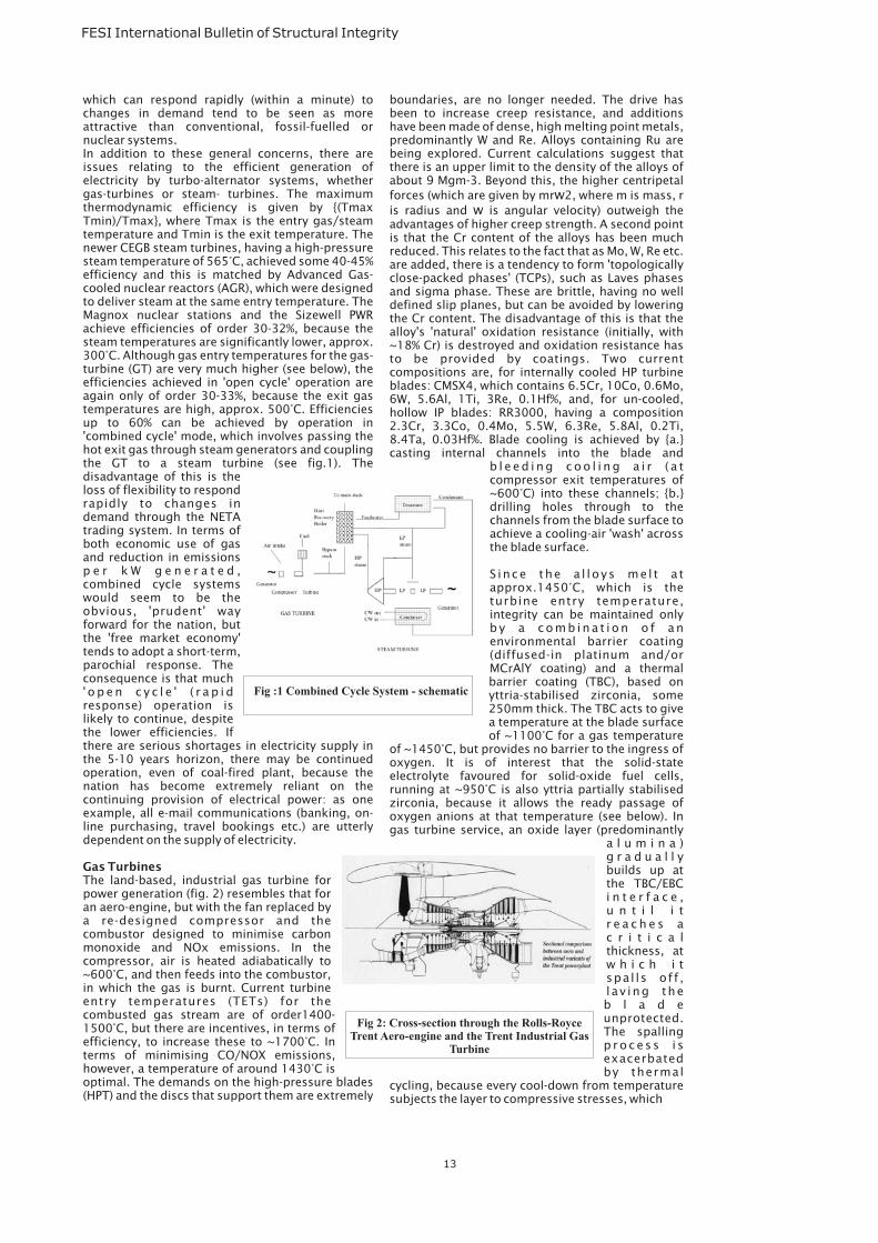
which can respond rapidly (within a minute) tochanges in demand tend to be seen as moreattractive than conventional, fossil-fuelled ornuclear systems.In addition to these general concerns, there areissues relating to the efficient generation ofelectricity by turbo-alternator systems, whethergas-turbines or steam- turbines. The maximumthermodynamic efficiency is given by {(TmaxTmin)/Tmax}, where Tmax is the entry gas/steamtemperature and Tmin is the exit temperature. Thenewer CEGB steam turbines, having a high-pressuresteam temperature of 565°C, achieved some 40-45%efficiency and this is matched by Advanced Gas-cooled nuclear reactors (AGR), which were designedto deliver steam at the same entry temperature. TheMagnox nuclear stations and the Sizewell PWRachieve efficiencies of order 30-32%, because thesteam temperatures are significantly lower, approx.300°C. Although gas entry temperatures for the gas-turbine (GT) are very much higher (see below), theefficiencies achieved in 'open cycle' operation areagain only of order 30-33%, because the exit gastemperatures are high, approx. 500°C. Efficienciesup to 60% can be achieved by operation in'combined cycle' mode, which involves passing thehot exit gas through steam generators and couplingthe GT to a steam turbine (see fig.1). Thedisadvantage of this is theloss of flexibility to respondrapidly to changes indemand through the NETAtrading system. In terms ofboth economic use of gasand reduction in emissionsp e r k W g e n e r a t e d ,combined cycle systemswould seem to be theobvious, 'prudent' wayforward for the nation, butthe 'free market economy'tends to adopt a short-term,parochial response. Theconsequence is that much' o p e n c y c l e ' ( r a p i dresponse) operation islikely to continue, despitethe lower efficiencies. Ifthere are serious shortages in electricity supply inthe 5-10 years horizon, there may be continuedoperation, even of coal-fired plant, because thenation has become extremely reliant on thecontinuing provision of electrical power: as oneexample, all e-mail communications (banking, on-line purchasing, travel bookings etc.) are utterlydependent on the supply of electricity.
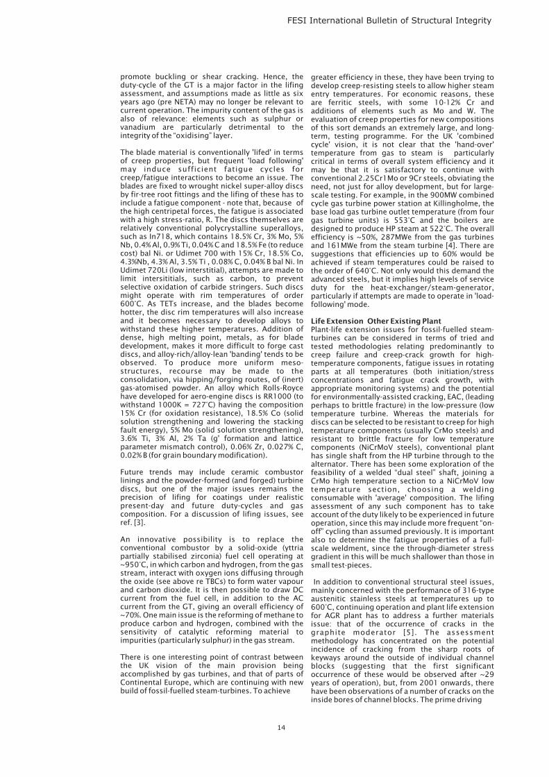
The land-based, industrial gas turbine forpower generation (fig. 2) resembles that foran aero-engine, but with the fan replaced bya re-designed compressor and thecombustor designed to minimise carbonmonoxide and NOx emissions. In thecompressor, air is heated adiabatically to~600°C, and then feeds into the combustor,in which the gas is burnt. Current turbineentry temperatures (TETs) for thecombusted gas stream are of order1400-1500°C, but there are incentives, in terms ofefficiency, to increase these to ~1700°C. Interms of minimising CO/NOX emissions,however, a temperature of around 1430°C isoptimal. The demands on the high-pressure blades(HPT) and the discs that support them are extremely
Gas Turbines
boundaries, are no longer needed. The drive hasbeen to increase creep resistance, and additionshave been made of dense, high melting point metals,predominantly W and Re. Alloys containing Ru arebeing explored. Current calculations suggest thatthere is an upper limit to the density of the alloys ofabout 9 Mgm-3. Beyond this, the higher centripetalforces (which are given by mr 2, where m is mass, ris radius and is angular velocity) outweigh theadvantages of higher creep strength. A second pointis that the Cr content of the alloys has been muchreduced. This relates to the fact that as Mo, W, Re etc.are added, there is a tendency to form 'topologicallyclose-packed phases' (TCPs), such as Laves phasesand sigma phase. These are brittle, having no welldefined slip planes, but can be avoided by loweringthe Cr content. The disadvantage of this is that thealloy's 'natural' oxidation resistance (initially, with~18% Cr) is destroyed and oxidation resistance hasto be provided by coatings. Two currentcompositions are, for internally cooled HP turbineblades: CMSX4, which contains 6.5Cr, 10Co, 0.6Mo,6W, 5.6Al, 1Ti, 3Re, 0.1Hf%, and, for un-cooled,hollow IP blades: RR3000, having a composition2.3Cr, 3.3Co, 0.4Mo, 5.5W, 6.3Re, 5.8Al, 0.2Ti,8.4Ta, 0.03Hf%. Blade cooling is achieved by {a.}casting internal channels into the blade and
b l e e d i n g c o o l i n g a i r ( a tcompressor exit temperatures of~600°C) into these channels; {b.}drilling holes through to thechannels from the blade surface toachieve a cooling-air 'wash' acrossthe blade surface.
S ince the a l loys me l t a tapprox.1450°C, which is theturbine entry temperature,integrity can be maintained onlyb y a c o m b i n a t i o n o f a nenvironmental barrier coating(diffused-in platinum and/orMCrAlY coating) and a thermalbarrier coating (TBC), based onyttria-stabilised zirconia, some250mm thick. The TBC acts to givea temperature at the blade surfaceof ~1100°C for a gas temperature
of ~1450°C, but provides no barrier to the ingress ofoxygen. It is of interest that the solid-stateelectrolyte favoured for solid-oxide fuel cells,running at ~950°C is also yttria partially stabilisedzirconia, because it allows the ready passage ofoxygen anions at that temperature (see below). Ingas turbine service, an oxide layer (predominantly
a l u m i n a )g r a d u a l l ybuilds up atthe TBC/EBCi n t e r f a c e ,u n t i l i tr e a c h e s ac r i t i c a lthickness, atw h i c h i tspa l ls of f ,l av ing theb l a d eunprotected.The spallingp r o c e s s i sexacerbatedby thermal
cycling, because every cool-down from temperaturesubjects the layer to compressive stresses, which
ww
13
FESI International Bulletin of Structural Integrity
Fig :1 Combined Cycle System - schematic
Fig 2: Cross-section through the Rolls-RoyceTrent Aero-engine and the Trent Industrial Gas
Turbine
FESI International Bulletin of Structural Integrity
promote buckling or shear cracking. Hence, theduty-cycle of the GT is a major factor in the lifingassessment, and assumptions made as little as sixyears ago (pre NETA) may no longer be relevant tocurrent operation. The impurity content of the gas isalso of relevance: elements such as sulphur orvanadium are particularly detrimental to theintegrity of the “oxidising” layer.
The blade material is conventionally 'lifed' in termsof creep properties, but frequent 'load following'may induce sufficient fatigue cycles forcreep/fatigue interactions to become an issue. Theblades are fixed to wrought nickel super-alloy discsby fir-tree root fittings and the lifing of these has toinclude a fatigue component - note that, because ofthe high centripetal forces, the fatigue is associatedwith a high stress-ratio, R. The discs themselves arerelatively conventional polycrystalline superalloys,such as In718, which contains 18.5% Cr, 3% Mo, 5%Nb, 0.4% Al, 0.9% Ti, 0.04% C and 18.5% Fe (to reducecost) bal Ni. or Udimet 700 with 15% Cr, 18.5% Co,4.3%Nb, 4.3% Al, 3.5% Ti , 0.08% C, 0.04% B bal Ni. InUdimet 720Li (low interstitial), attempts are made tolimit intersititials, such as carbon, to preventselective oxidation of carbide stringers. Such discsmight operate with rim temperatures of order600°C. As TETs increase, and the blades becomehotter, the disc rim temperatures will also increaseand it becomes necessary to develop alloys towithstand these higher temperatures. Addition ofdense, high melting point, metals, as for bladedevelopment, makes it more difficult to forge castdiscs, and alloy-rich/alloy-lean 'banding' tends to beobserved. To produce more uniform meso-structures, recourse may be made to theconsolidation, via hipping/forging routes, of (inert)gas-atomised powder. An alloy which Rolls-Roycehave developed for aero-engine discs is RR1000 (towithstand 1000K = 727°C) having the composition15% Cr (for oxidation resistance), 18.5% Co (solidsolution strengthening and lowering the stackingfault energy), 5% Mo (solid solution strengthening),3.6% Ti, 3% Al, 2% Ta (g' formation and latticeparameter mismatch control), 0.06% Zr, 0.027% C,0.02% B (for grain boundary modification).
Future trends may include ceramic combustorlinings and the powder-formed (and forged) turbinediscs, but one of the major issues remains theprecision of lifing for coatings under realisticpresent-day and future duty-cycles and gascomposition. For a discussion of lifing issues, seeref. [3].
An innovative possibility is to replace theconventional combustor by a solid-oxide (yttriapartially stabilised zirconia) fuel cell operating at~950°C, in which carbon and hydrogen, from the gasstream, interact with oxygen ions diffusing throughthe oxide (see above re TBCs) to form water vapourand carbon dioxide. It is then possible to draw DCcurrent from the fuel cell, in addition to the ACcurrent from the GT, giving an overall efficiency of~70%. One main issue is the reforming of methane toproduce carbon and hydrogen, combined with thesensitivity of catalytic reforming material toimpurities (particularly sulphur) in the gas stream.
There is one interesting point of contrast betweenthe UK vision of the main provision beingaccomplished by gas turbines, and that of parts ofContinental Europe, which are continuing with newbuild of fossil-fuelled steam-turbines. To achieve
greater efficiency in these, they have been trying todevelop creep-resisting steels to allow higher steamentry temperatures. For economic reasons, theseare ferritic steels, with some 10-12% Cr andadditions of elements such as Mo and W. Theevaluation of creep properties for new compositionsof this sort demands an extremely large, and long-term, testing programme. For the UK 'combinedcycle' vision, it is not clear that the 'hand-over'temperature from gas to steam is particularlycritical in terms of overall system efficiency and itmay be that it is satisfactory to continue withconventional 2.25Cr1Mo or 9Cr steels, obviating theneed, not just for alloy development, but for large-scale testing. For example, in the 900MW combinedcycle gas turbine power station at Killingholme, thebase load gas turbine outlet temperature (from fourgas turbine units) is 553°C and the boilers aredesigned to produce HP steam at 522°C. The overallefficiency is ~50%, 287MWe from the gas turbinesand 161MWe from the steam turbine [4]. There aresuggestions that efficiencies up to 60% would beachieved if steam temperatures could be raised tothe order of 640°C. Not only would this demand theadvanced steels, but it implies high levels of serviceduty for the heat-exchanger/steam-generator,particularly if attempts are made to operate in 'load-following' mode.
Plant-life extension issues for fossil-fuelled steam-turbines can be considered in terms of tried andtested methodologies relating predominantly tocreep failure and creep-crack growth for high-temperature components, fatigue issues in rotatingparts at all temperatures (both initiation/stressconcentrations and fatigue crack growth, withappropriate monitoring systems) and the potentialfor environmentally-assisted cracking, EAC, (leadingperhaps to brittle fracture) in the low-pressure (lowtemperature turbine. Whereas the materials fordiscs can be selected to be resistant to creep for hightemperature components (usually CrMo steels) andresistant to brittle fracture for low temperaturecomponents (NiCrMoV steels), conventional planthas single shaft from the HP turbine through to thealternator. There has been some exploration of thefeasibility of a welded “dual steel” shaft, joining aCrMo high temperature section to a NiCrMoV lowtemperature section, choosing a weldingconsumable with 'average' composition. The lifingassessment of any such component has to takeaccount of the duty likely to be experienced in futureoperation, since this may include more frequent “on-off” cycling than assumed previously. It is importantalso to determine the fatigue properties of a full-scale weldment, since the through-diameter stressgradient in this will be much shallower than those insmall test-pieces.
In addition to conventional structural steel issues,mainly concerned with the performance of 316-typeaustenitic stainless steels at temperatures up to600°C, continuing operation and plant life extensionfor AGR plant has to address a further materialsissue: that of the occurrence of cracks in thegraphite moderator [5]. The assessmentmethodology has concentrated on the potentialincidence of cracking from the sharp roots ofkeyways around the outside of individual channelblocks (suggesting that the first significantoccurrence of these would be observed after ~29years of operation), but, from 2001 onwards, therehave been observations of a number of cracks on theinside bores of channel blocks. The prime driving
Life Extension Other Existing Plant
14
FESI International Bulletin of Structural Integrity
force for this is the shrinkage of graphite underneutron irradiation (indeed, the pattern of cracksbears some resemblance to that of a 'crackle glaze' onChinese pottery, which is produced by thermalshrinkage of the glaze material on cooling), but thesituation is complicated by the simultaneous(gamma-ray) irradiation-enhanced oxidation of thegraphite. The presence of the cracks as they exist atpresent does not provide any threat to structuralintegrity, but there are concerns that their futuredevelopment with time could conceivably allowsufficient movement in the core as a whole for safeoperation to be challenged. Concern is such thatthree years ago, the NII set up a Graphite TechnicalAdvisory Committee (GTAC), akin to the industry-funded Technical Advisory Committee on StructuralIntegrity (TAGSI), to give independent advice on theissues.
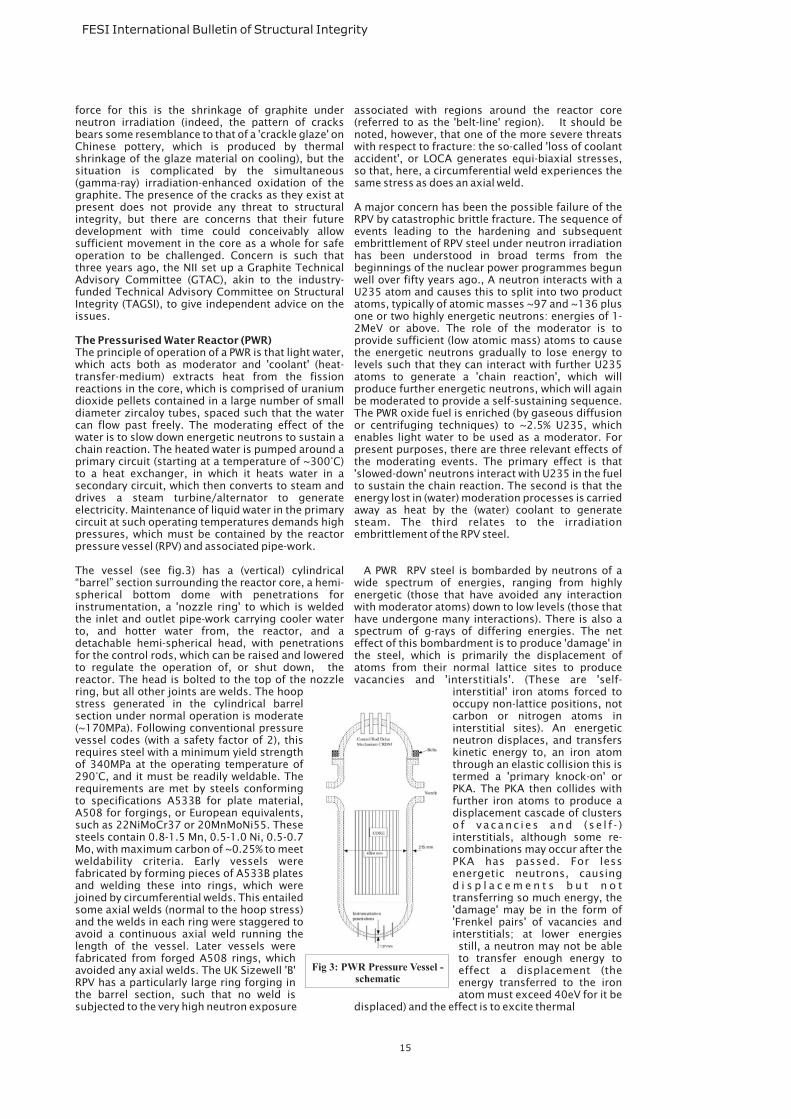
The principle of operation of a PWR is that light water,which acts both as moderator and 'coolant' (heat-transfer-medium) extracts heat from the fissionreactions in the core, which is comprised of uraniumdioxide pellets contained in a large number of smalldiameter zircaloy tubes, spaced such that the watercan flow past freely. The moderating effect of thewater is to slow down energetic neutrons to sustain achain reaction. The heated water is pumped around aprimary circuit (starting at a temperature of ~300°C)to a heat exchanger, in which it heats water in asecondary circuit, which then converts to steam anddrives a steam turbine/alternator to generateelectricity. Maintenance of liquid water in the primarycircuit at such operating temperatures demands highpressures, which must be contained by the reactorpressure vessel (RPV) and associated pipe-work.
The vessel (see fig.3) has a (vertical) cylindrical“barrel” section surrounding the reactor core, a hemi-spherical bottom dome with penetrations forinstrumentation, a 'nozzle ring' to which is weldedthe inlet and outlet pipe-work carrying cooler waterto, and hotter water from, the reactor, and adetachable hemi-spherical head, with penetrationsfor the control rods, which can be raised and loweredto regulate the operation of, or shut down, thereactor. The head is bolted to the top of the nozzlering, but all other joints are welds. The hoopstress generated in the cylindrical barrelsection under normal operation is moderate(~170MPa). Following conventional pressurevessel codes (with a safety factor of 2), thisrequires steel with a minimum yield strengthof 340MPa at the operating temperature of290°C, and it must be readily weldable. Therequirements are met by steels conformingto specifications A533B for plate material,A508 for forgings, or European equivalents,such as 22NiMoCr37 or 20MnMoNi55. Thesesteels contain 0.8-1.5 Mn, 0.5-1.0 Ni, 0.5-0.7Mo, with maximum carbon of ~0.25% to meetweldability criteria. Early vessels werefabricated by forming pieces of A533B platesand welding these into rings, which werejoined by circumferential welds. This entailedsome axial welds (normal to the hoop stress)and the welds in each ring were staggered toavoid a continuous axial weld running thelength of the vessel. Later vessels werefabricated from forged A508 rings, whichavoided any axial welds. The UK Sizewell 'B'RPV has a particularly large ring forging inthe barrel section, such that no weld issubjected to the very high neutron exposure
The Pressurised Water Reactor (PWR)
associated with regions around the reactor core(referred to as the 'belt-line' region). It should benoted, however, that one of the more severe threatswith respect to fracture: the so-called 'loss of coolantaccident', or LOCA generates equi-biaxial stresses,so that, here, a circumferential weld experiences thesame stress as does an axial weld.
A major concern has been the possible failure of theRPV by catastrophic brittle fracture. The sequence ofevents leading to the hardening and subsequentembrittlement of RPV steel under neutron irradiationhas been understood in broad terms from thebeginnings of the nuclear power programmes begunwell over fifty years ago., A neutron interacts with aU235 atom and causes this to split into two productatoms, typically of atomic masses ~97 and ~136 plusone or two highly energetic neutrons: energies of 1-2MeV or above. The role of the moderator is toprovide sufficient (low atomic mass) atoms to causethe energetic neutrons gradually to lose energy tolevels such that they can interact with further U235atoms to generate a 'chain reaction', which willproduce further energetic neutrons, which will againbe moderated to provide a self-sustaining sequence.The PWR oxide fuel is enriched (by gaseous diffusionor centrifuging techniques) to ~2.5% U235, whichenables light water to be used as a moderator. Forpresent purposes, there are three relevant effects ofthe moderating events. The primary effect is that'slowed-down' neutrons interact with U235 in the fuelto sustain the chain reaction. The second is that theenergy lost in (water) moderation processes is carriedaway as heat by the (water) coolant to generatesteam. The third relates to the irradiationembrittlement of the RPV steel.
A PWR RPV steel is bombarded by neutrons of awide spectrum of energies, ranging from highlyenergetic (those that have avoided any interactionwith moderator atoms) down to low levels (those thathave undergone many interactions). There is also aspectrum of g-rays of differing energies. The neteffect of this bombardment is to produce 'damage' inthe steel, which is primarily the displacement ofatoms from their normal lattice sites to producevacancies and 'interstitials'. (These are 'self-
interstitial' iron atoms forced tooccupy non-lattice positions, notcarbon or nitrogen atoms ininterstitial sites). An energeticneutron displaces, and transferskinetic energy to, an iron atomthrough an elastic collision this istermed a 'primary knock-on' orPKA. The PKA then collides withfurther iron atoms to produce adisplacement cascade of clusterso f vacanc i e s and ( se l f - )interstitials, although some re-combinations may occur after thePKA has passed. For lessenergetic neutrons, causingd i s p l a c e m e n t s b u t n o ttransferring so much energy, the'damage' may be in the form of'Frenkel pairs' of vacancies andinterstitials; at lower energiesstill, a neutron may not be ableto transfer enough energy toeffect a displacement (theenergy transferred to the ironatom must exceed 40eV for it be
displaced) and the effect is to excite thermal
15
Fig 3: PWR Pressure Vessel -schematic
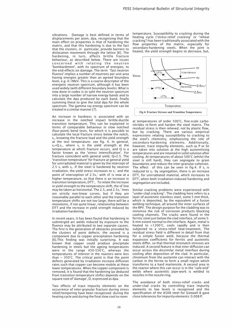
vibrations. Damage is best defined in terms ofdisplacements per atom, dpa, recognising that themain effect on properties is that of hardening thematrix, and that this hardening is due to the factthat the clusters, in particular, provide barriers todislocation movement through the lattice [6]. Thehardening, in turn, affects brittle fracturebehaviour, as described below. There are issuesconce rned w i th r e l a t i ng the neu t ron'bombardment', with its spectrum of energies, tothe end-effects on damage. The term 'fast neutronfluence' implies a number of neutrons per unit areahaving energies greater than an agreed boundarylevel, e.g. 0.1MeV. This is a coarse descriptor of theenergetic neutron spectrum, although it has beenused widely (with different boundary levels). What isnow done in codes is to split the neutron spectruminto a large number of narrow energy bands and tocalculate the dpa produced by each band, finallysumming these to give the total dpa for the wholespectrum. The gamma ray energy spectrum can betreated in a similar manner [7].
An increase in hardness is associated with anincrease in the notched impact brittle-ductiletransition temperature. This can be explained interms of comparable behaviour in slow notched(four-point) bend tests, for which it is possible tocalculate the local fracture stress below the notch,s , knowing the fracture load and the yield strengthat the test temperature: see fig. 4. In general,s =Q.s , where s is the yield strength at thetemperature at which fracture occurs, and Q is afactor known as the 'stress intensification'. Forfracture coincident with general yield, Q=2.5. The'transition temperature' for fracture at general yieldfor unirradiated material is given by the intercept of2.5 s with s . If the steel is hardened by neutronirradiation, the yield stress increases to s and thepoint of interception of 2.5s with sF is now at ahigher temperature, so that there is an increase intransition temperature, DTT . To relate the increasein yield strength to the temperature shift, the sF linemay be taken as horizontal. The 2.5 and 2.5s linesare strictly non-linear curves, but if they arereasonably parallel to each other and the transitiontemperature shifts are not too large, there will be amonotonic, if not quite linear, relationship betweenDTT and the increase in yield strength induced byirradiation hardening.
In recent years, it has been found that hardening insubmerged arc welds induced by exposure to thefluence may be attributed to two separate causes.The first is the generation of obstacles provided bythe clusters of point defects; the second is acomponent due to copper precipitation hardening[6].This finding was initially surprising. It wasknown that copper could produce precipitatehardening in steels but the ageing temperatureswere in the range 450-550°C, whereas thetemperatures of interest in the reactors were lessthan ~ 350°C. The critical point is that the pointdefects generated by irradiation increase diffusionrates such that copper can become mobile at theselower temperatures. When the copper component isremoved, it is found that the hardening (as deducedfrom transition temperature shifts) depends on thesquare root of 'damage', D, expressed as dpa.
Two effects of trace impurity elements on theoccurrence of inter-granular fracture during stressrelief/tempering have been recognised: during theheating cycle and during the final slow cool to room
F
F Y Y
Y F
Y
Y
1
Y Y
+
+
+
temperature. Susceptibility to cracking during theheating cycle (“stress-relief cracking” or “reheatcracking”) has been traditionally associated with theflow properties of the matrix, especially forsecondary-hardening steels. When the joint isheated, the yield strength begins to decrease, but,
at temperatures of order 500°C, fine-scale carbo-nitrides re-form and harden the steel matrix. Theresidual stress is then relieved, not by plastic flow,but by cracking. There are various empiricalexpressions relating susceptibility to cracking tothe steel's chemistry, emphasising the role ofsecondary-hardening elements. Additionally,however, trace impurity elements, such as P or Snare taken into solution at the high austenitisingtemperatures and are retained in solid solution aftercooling. At temperatures of about 500°C (whilst thesteel is still hard), they can segregate to grainboundaries and reduce the inter-granular cohesion.The effect of this can be seen in fig.4. If s isreduced to s - by segregation, there is an increaseDTT for unirradiated material, which increases toDTT when both irradiation-induced hardening andsegregation are included.
Similar cracking problems were experienced with“under-clad cracking”. The cladding here refers to alayer of austenitic stainless steel, some 5 mm thick,which is deposited, by the equivalent of a fusionwelding technique, all around the inner surfaces ofthe RPV. The design purpose for the cladding was tominimise the risk of corrosion products blockingcooling channels. The cracks were found in theferritic steel just below the clad interface, of some 5-6 mm extent normal to the interface. Again, metal isheated to >1200°C, cools rapidly and is thensubjected to a stress-relief heat-treatment, Theresidual stress field is different in detail from thatfor a simple fusion weld, because the thermalexpansion coefficients for ferritic and austeniticsteels differ, so that thermal mismatch stresses areinduced. A second feature is that inter-diffusion canoccur across the dissimilar metal interface duringcooling after deposition of the clad. In particular,chromium from the austenite can interact with thecarbon in the ferrite to form a small region whichtransforms to a hard martensite. A second area inthe reactor where this can occur is in the “safe-end”welds where austenitic pipe-work is welded tonozzles in the nozzle ring.
The avoidance of both stress-relief cracks andunder-clad cracks by controlling trace impurityelements to low levels is recognised and thespecification of the A508 steel for Sizewell B gaveclose tolerances for impurity elements: 0.008 P;
F
F
2
3
FESI International Bulletin of Structural Integrity
16
Fig 4: Fracture Stresses and Transition Temperatures
0.008 S; 0.01 Sn; 0.008 Sb. An added benefit maybe that low levels of impurities are beneficial withrespect to resistance to environmentally assistedcracking (EAC). Such specifications lead to addedcost, and it is likely that, in any “new build” scenario,the need for such tight specifications will besubjected to close scrutiny. In fact, the control ofwater chemistry in modern PWR systems is so goodthat it is possible to contemplate un-clad RPVs, andthe question of whether any potential “new build”PWR would be clad or unclad remains open.
The 'new build' options for nuclear plant will almostcertainly focus on two systems: the EuropeanPressurised Water Reactor (EPR) similar to that beingconstructed in Finland, and the WestinghouseAdvanced Pressurised Water Reactor (AP1000)recently licensed in the USA. The AP1000 includesmany 'passive' safety features, such as naturalwaste heat removal in the event of a shut down forsafety reasons, and is designed on a modular basis,with many components being interchangeable. Thedesign life is set at 60 years. Sizewell B was built toexceptionally high standards, with meticulousattention paid not only to the fine detail of steelcomposition, but, in particular to the number, andmultiplicity, of pre-service inspections undergoneby the pressure vessel. In the environment of 'freemarket' 21st Century Britain, the necessity for sucha detailed, costly, appraisal will be challenged.Indeed, the NII is now proposing that regulationmight proceed by approving the generic design andpaying further individual attention only to thespecific site conditions. This is radically differentfrom the traditional UK approach, which had to dealwith some twenty nuclear stations, almost all ofwhich had significant differences between them,but is not dissimilar for what would be done by theCivil Aviation Authority in clearing a new aircraft oraero-engine. What is needed critically is to assesswhere the attention to fine detail is of paramountimportance and where general (already high)industry standards will suffice. Unfortunately, in theabsence of firm bids for nuclear 'new build' systems,funding for such appraisal work has not yet beenmade available. As noted above, one set of issues islikely to involve the effects of trace impurityelements and heat-treatment/welding conditionson resistance to EAC in PWR water. Here, it is alsonecessary to evaluate the possible effect of(gamma-ray) irradiation enhancement on thecorrosion processes, to determine the magnitude ofany radiolytic component.
For the future, other possible nuclear systems arethe high temperature reactor (HTR), the fast reactorand the fusion reactor. Of these, it is possible thatthe HTR could enter service, somewhere in theWorld, by 2015-2020. One version: the Pebble BedModular Reactor (PBMR); has reached a high state ofdevelopment in South Africa. It works on theBrayton cycle, with helium gas as coolant, flowingthrough an assembly of 'pebbles' formed by theagglomeration of a large number of micro-spherescomposed of a core of graphite and a number ofdeposited 'shells' of ceramic (SiC) and furthergraphite. The gas entry temperature is ~500°C andit is heated to ~900°C as it leaves the pebble bedassembly. It is compressed and then drives aconventional turbine, before cooling and beingpumped back to the pebble bed. The system isdesigned to give a completely safe shutdown, withnatural heat decay. There is no clear evidence of
Other Nuclear Systems
major structural integrity issues at this stage: onesuspicion is that, in commercial service, it may bedifficult to prevent helium leaks; this is more likelyto be a commercial concern than a safety hazard.
An opportunity that seems available for the PBMR isto replace a conventional nickel-base turbinesystem with a ceramic turbine (SiN, SiC orcomposite). This would be much lighter(remembering that helium has low density, hencelimiting the kinetic energy available), yet able tooperate comfortably at 900°C in an inert gasatmosphere.
Fast reactors, based on transmutation of U238 toPu239, followed by radioactive decay of the Pu, havebeen in existence for potential civil powergeneration for over twenty years. Studies for theEuropean Fast Reactor (EFR) were being made in thelate 1980s. Japan has plant operating at Monju. Themain issue is not the transmutation or radio-activedecay aspects (production of plutonium for bombshas been continuing since the Second World War),but the safe and reliable generation of electricalpower. The primary circuit coolant is liquid sodiumand this is passed, at ~500°C, through a steam-generator, to raise steam from water. The sodiumpasses through tubes of perhaps 30m length,~10mm diameter and 2mm wall-thickness. On theother side of these tubes is liquid water. Any sodiumleak into the water will cause a violent chemicalreaction. The number and closeness of spacing ofsuch tubes provides major challenges to assemblyand makes in-service inspection non-viable. In onedesign, ~38 km of tubing is drawn through hard-faced spacer plates, separated at ~1 m intervals.Guaranteeing that no tube is scratched to onequarter (0.5 mm) or even one half (1mm) is adaunting task: the only form of monitoring availableis to measure the drawing force. Given the 400°Ctemperature differential in the workable PBMR andan equal (if not greater) temperature differentialbetween 500°C and 100oC/RT in the fast reactor, itis tempting to suggest that one might explore a fastreactor heat source, liquid sodium coolant, but aninert gas (argon) plus compressors to drive theturbine. The fusion reactor is still in the researchstage and, almost certainly, will not be producingelectricity for the nation in the 2025 timescale. Theplasma, in which the deuterium/tritium fusionprocesses take place, is electrically charged and canbe confined in a toroidal magnetic field. Thegeneration of electrical power is achieved, however,not by any coupling with the plasma, but by the factthat, in the nuclear reactions, a number of neutronsare produced. These are highly energetic (up to14MeV) and, because they are uncharged, they canescape from the confining magnetic field and 'shootinto' the so-called 'blanket material', which is a largecylindrical block of steel surrounding the plasma.The displacements and thermal vibrations inducedin the blanket produce heat, which is extracted (atabout 500°C) by water flowing through longitudinalholes running through the blanket. The blanketmaterial is likely to be a steel of the 9-12 Cr type, butMo can be activated by the neutrons, and so thesteel may contain Nb. Mention has been made ofinternally oxidised alloys, but the fabrication of verylarge blocks may not be easy to achieve. Theinterior, plasma-facing 'front wall' of the block hasto be constructed from a material that will not erodetoo rapidly under bombardment from the neutrons:tungsten is one favoured option.
FESI International Bulletin of Structural Integrity
17
FESI International Bulletin of Structural Integrity
of this size, but another potential system is awood/epoxy laminate. The design parametersrelate to strength/weight; stiffness/weight andfatigue strength/weight. The strength/weight ratiofor the glass/epoxy is ~25% higher than that for thewood/epoxy, which makes the wood/epoxy ~25%heavier. On the other hand, the stiffness/weightratio for glass/epoxy is only ~90% of that forwood/epoxy. This effect is amplified in bending,where the tip deflection for a blade made inwood/epoxy is only 75% of that for glass/epoxy.The fatigue strength/weight ratio is identical for thetwo options. Superficially, blades are notparticularly complex structures and there isexperience of wind farm operation. Structuralintegrity issues for normal, land-based wind farmsshould be readily manageable, although someblade failures have occurred. Concerns exist mainlywith the absolute size of the large blades and withthe conditions encountered in offshore operation.There have been some spectacular failures of large,sea-going catamarans built from glass-fibre/epoxycomposites, although, arguably, these have beenassociated with the failure of fixing points wherethe linking cross-spars join the hulls. There mayalso be issues with an offshore farm, as opposed toan individual turbine, if the array of blades producesanything in the nature of a vortex. The importanceof monitoring, inspection and maintenance isemphasised.
References(1) DTI Initial Contribution to the PIU Energy Policy
Review, August 2001
(2) “The Energy Challenge: Energy Review Report” DTICm 6887 July 2006
(3) Knott J.F. “The Durability of Rotating Componentsin Gas Turbines” in “PARSONS 2000: AdvancedMaterials for 21st Century Turbines and PowerPlant” ed. A.Strang et al. IOM Communications Ltd.2000, pp 950-960.
(4) Chappell T.E. “The 900 MW Combined Cycle GasTurbine Power Station Project at Killingholme” Proc.Instn. Mech. Engrs. 1993, Vol.207 pp 147-155
(5) “The Guardian” 7 July 2006
(6) Knott J.F. and English C.A. “Views of TAGSI on thePrinciples underlying the Assessment of theMechanical Properties of Irradiated Ferritic SteelPressure Vessels”. Intl. Jnl. of Press. Vessels andPiping, 1999 Vol.76, pp 891-908
(7) Knott J.F., English C.A., Weaver, D.R. and LidburyD.P.G “Views of TAGSI on the effects of gammairradiation on the mechanical properties ofirradiated ferritic steel reactor pressure vessels” Intl.Jnl. of Press Vessels and Piping 2005 Volume 82, pp929-940,
(8) Little E.A. “Development of Radiation ResistantMaterials for Advanced Power Plant” Mat. Sci. Tech.2006 Vol. 22, pp 491-518
(9) Cottrell G.A. “A Study of Plasma Facing Materials forFusion Power Plants” Mat. Sci. Tech 2006 Vol. 22 pp860-880
(10) Thompson M.W. “Energy in the Landscape” TheRoyal Institution Proceedings 1990, Vol. 63,pp113-136
Professor John Knott OBE, FRS, FREng is the FeeneyProfessor of Metallurgy and Materials at the Universityof Birmingham with a particular interest in fractureand crack arrest. This paper was originally given at theInternational Conference on Engineering StructuralIntegrity - ESIA 8 -”Throughlife Mangement ofStructures and Components” - October 2006 -Manchester.
There are recent excellent reviews on materials foradvanced nuclear power plant by Little [8] and onplasma-facing materials by Cottrell [9].
Under this heading, there are several postulatedsystems: including water turbines (for bothconventional hydro-electric generation or wave-power) tidal basins and/or barrages, solar cells, and,of course, wind. Bio-mass fuelled systems are'renewable' but generate carbon dioxide in theircombusted products. Fuel cells can run on hydrogenalone, but the commercial systems are planned torun on reformed methane or similar hydrocarbonsfor electricity generation, or methanol fortransportation. The prospect of hydrogen as a cleanfuel is extremely appealing, but hydrogen needs tobe generated by electrolysis of water, which impliesa source of electrical power! The overall prospect, asfar as the UK is concerned has been elegantlysummarised by Thompson in his paper ”Energy inthe Landscape” [10]. He calculates the size of systemneeded to meet the UK's total electrical powerdemand for each of the various methods. Onconventional hydro, for example, the UK has verylittle water at heights greater than 1000 m above sealevel, yet would require an area some ten times thatof the British Isles; a tidal basin would need to beroughly the size of (all) Ireland. With converters of100% efficiency and continuous sunshine from aclear sky, the total area of solar panel required isabout 50% bigger than the Isle of Wight: currentefficiencies for silicon-based panels are of order10%; the sun does not shine continuously; andsilicon-based panels are not just expensive, butneed significant amounts of energy to produce. For2 m high waves, the catchment needs to beapproximately three times the length of the SouthCoast: for a 20 knot wind, it is the length of the SouthCoast and 500 m high! It is clear that our existingfossil-fuelled or nuclear generation systems at leasthave the virtue of being relatively compact.
The generation of electricity by wind power is not anew development: Nansen had a wind generator onboard the “Fram” in 1894 when he went “FarthestNorth”. The Netherlands have been using significantwind generation for some years. Over the last fiveyears, the UK Government has actively encouragedthe development of wind-power generation byoffering financial incentives. Large wind farms haveappeared, often on moor land, sometimes vergingon sites of natural beauty. Offshore sites are alsobeing developed. Remote sites tend to be moredifficult to access for inspection, maintenance andrepair and these aspects will assume moreimportance as we generate higher percentages ofelectricity by wind-power and as the systems'mature' (i.e. age). In October 2006, the “World'sbiggest offshore turbine” was towed out to theBeatrice field in the Moray Firth, Scotland. The 1000tonnes structure measures 120m above sea level,with blades 63 m long. It will generate 5 MW ofelectricity. It is clearly necessary to have 200 suchturbines to generate 1000MW of electricity and theassoc ia ted moni tor ing, inspect ion andmaintenance of such a large assembly is likely to bemuch more labour-intensive than that for aconventional station.
The material for blades of these large sizes (2x63 =126m is greater than the size of most cricket fields)is most likely to be a glass-fibre/epoxy composite,with a volume fraction of some 50% fibres. Carbonfibre composites are too expensive for components
Renewables
18
FESI International Bulletin of Structural Integrity
INTRODUCTION
AWARENESS OF AGEING
Many UK industrial companies are seeking tomaximise the life of their equipment containinghazardous fluids or pressure, and fewerinstallations are being replaced with new-build.Equipment therefore needs to be kept workingsafely and reliably for longer. In order to addressconcerns over the way some parts of UK industry ismanaging equipment that is degrading by time-dependant mechanisms the Health and SafetyExecutive (HSE) commissioned 'The Plant AgeingGuide: Management of Equipment ContainingHazardous Fluids or Pressure', published as HSEResearch Report RR509. The document is a practicalguide discussing the issues to be considered formanaging ageing equipment, and its aim is to helpthose responsible for equipment containinghazardous fluids or pressure to understand andassess the risks of accumulated damage anddeterioration, and to manage their equipment overtime to ensure that it stays safe and reliable.
RR509 has been publicly available from the HSEwebsite since November 2006, and a number ofrelated seminars on the management of ageingplant have been run by the IMechE and ABB. Thispaper aims to provide an overview of the maincontent of the Guide. However, at over 100 pages,the Guide itself contains substantially moreinformation, and covers topics in more depth than ispossible in this paper. RR509 is presented in fourdistinct chapters, covering the main steps in themanagement of ageing equipment, and this articlesummarises some of the key elements from eachsection:
Awareness of ageing “Could myequipment be ageing?”
Identification of ageing damage: “How can Itell if ageing is happening?”
Addressing ageing: “What do I do about it?”
Getting organised for managing ageing:“How can my organisation be prepared?”
It is important to appreciate that ageing is not abouthow old your equipment is; it's about what you knowabout its condition, and how that's changing overtime. Those who have responsibility for owning andoperating equipment often find that they wish to runit beyond the original stated design life, to changeits operating conditions, or to purchase and operatesecond hand equipment. However, there is also aneed to ensure the equipment's ongoing structuralintegrity and safety. An awareness of the risks ofaccumulated damage and deterioration ofequipment is vital for these situations and manyothers.
Much of the assessment is good engineeringjudgement, but it is required over a broad range ofdisciplines, and many of the topics interlink.
�
�
�
�
:
One model for understanding ageing is to considerthe four stages of equipment life:
is 'Initial' when the equipment has beencommissioned and installed, and has aprobability of failures occurring due to issuessuch as shake-down, faults that were notanticipated during design, or problems withthe installation such as bolting or valvesleaking.
is 'Maturity' when the equipment isoperating within it design limits, and routinemaintenance is carried out. Most of theequipment's life will be in Stage 2 when theprobability of failure is lowest.
is 'Ageing' when the equipment'sdesign life has been used, or when degradationbecomes evident, and a justification must bemade for continued service. A change of serviceconditions may also put equipment into Stage3. At the Ageing stage, equipment needsregular inspection, and repairs or modificationsmay be necessary.
is the 'Terminal' stage, whenaccelerating and accumulating damage toequipment means that repair and/orreplacement is necessary. The equipment hasreached its end-of-life, when no further servicecan be justified on safety or financial grounds.
Understanding where equipment may be in itslifetime, relative to the four stages, is an importantstep in managing equipment ageing.
The symptoms of ageing cover a large number ofindicators and damage mechanisms. Many of thesewill be obvious to day-to-day operators whenequipment starts to suffer from leaks, vibration,drips, valves seizing up, reduced pumpingefficiency, noise, repeated problems, impurities inthe product or ultimately, breakdown. Othersymptoms of deterioration such as wall-thinning,wear, corrosion, numerous types of cracking,blisters or fretting may need to be detected frominspection and non-destructive testing (NDT). Thosewith a good awareness of ageing should considercarrying out inspection for the latter set ofsymptoms when one or more of the former set ofsymptoms is evident. Understanding what kind ofdegradation and damage the equipment may be atrisk from will play a big role in tailoring the type ofinspection carried out.
In addition to detecting the damage, there are anumber of risk factors that can also makedeterioration more likely. The risk can be increased,for example, when equipment is under cyclicloading but without a fatigue assessment (either if itwas constructed to an old code, or has exceeded its
Stage 1
Stage 2
Stage 3
Stage 4
IDENTIFICATION OF AGEING
19
'The Plant Ageing Guide: Management of Equipment ContainingHazardous Fluids or Pressure', - HSE Research Report RR 509.A review by Dr Phillpa Moore of TWI on behalf of the HSE
FESI International Bulletin of Structural Integrity
original fatigue limit), or from changing the serviceconditions without revalidation. A lack ofknowledge can also increase the risk ofdeterioration - if there is no awareness of thepossibility of ageing, then the risk is that isoccurring will not be avoided. In addition, anabsence of information, such as when purchasingsecond hand equipment, may not provide sufficientconfidence that the condition of the equipment canbe known.
NDT and inspection plays a vital role in managingageing equipment, when it is necessary to ensureequipment integrity to justify continued service.The type of inspection carried out will depend onthe stage of the equipment within its lifecycle. InStages 1 and 2 the inspection will be 'confirmatory',but will become more 'deterministic' in Stage 3 and4. Confirmatory inspection is when the expectedcondition of the equipment is simply confirmed,typically using techniques such as routine manualultrasonic testing (UT) and magnetic particle or dyepenetrant testing. When equipment in an unknowncondition needs to be monitored, or it becomesnecessary to quantitatively measure flaw sizes,deterministic inspection is done, possibly usingmethods such as automated UT techniques. Thescheme of examination must therefore be reviewedat suitable intervals, as the equipment passesthrough the stages of its life when a differentapproach to the inspection becomes necessary. Thetopic of NDT and inspection is discussed in moredetail in the Guide.
By this point, with a good awareness of the risk ofequipment ageing, and knowing what damage tolook for and how to detect it, those responsiblefor equipment containing pressure or hazardousfluid should be in a good position to address anyageing damage that is found. Any action takenneeds to be carefully considered, depending onthe damage found. There are only a limitednumber of options to choose from, andsometimes more than one will be chosen::
Do a fitness-for-service, or remaining lifeassessment
Remove the damage, possibly withoutfurther repair
Repair the vessel (may be either atemporary or permanent repair)
De-rate the vessel service conditions
Monitor the vessel to ensure rate ofd a m a g e a c c u m u l a t i o n d o e s n o tcompromise safety
Scrap the vessel
A fitness-for-service assessment can be a good firststep to determine what further action is necessaryand can be carried out to assess damage such asfatigue cracking, locally thinned areas or dents and
ADDRESSING AGEING
�
�
�
�
�
�
gouges. It can assess whether the damage istolerable and may be left, or needs to be repaired.Alternatively, it can determine a safe lower servicestress for which the flaw is tolerable.
When surface and near surface flaws are found, themost common approach is to remove the flawedmaterial by grinding. After grinding and subsequentNDT, the remaining wall thickness can be measuredto determine whether it is still sufficient, withoutfurther repair welding. When making weld repairs toexisting equipment, the potential for defects to beintroduced may be greater than when the item wasnew. For weld repairs, appropriately qualified andexperienced personnel are essential. There arespecialist welding techniques which can carefullycontrol the repair weld heat input to offset thedisadvantages of a lack of post weld heat treatment.
Repair is not necessarily the most cost effectivemethod of dealing with damage to equipment.Consideration can also be given to the possibility ofrevalidation to justify changes to the operatingconditions of the equipment, which can thenpreclude the need for any repair. Examples whererevalidation for changes of service conditions orequipment modifications is particularly critical are;the operation of ferritic steel equipment at lowertemperatures where the material might show asignificant drop in fracture toughness; changes tothe contents or environment such that unforeseendamage mechanisms could occur (e.g. stresscorrosion cracking); or physical modifications thatwould limit access to critical locations forinspection.
Equipment will not be able to continue in service forever, and ultimately the equipment will need to bescrapped or replaced. The decision for when thiswill occur is often based on financial considerations,when the cost of ongoing operation, repairs andrevalidation, along with the combination of risk andconsequences of failure, becomes greater than thecost of replacement.
The management of ageing equipment requiresknowledge and expertise across a wide range ofdisciplines, found in a team of people, be it all in-house, or through selected sub-contractors. Thecompetencies required include:
Awareness of safety codes and regulations
Pressure/chemical plant engineering
Familiarity with the equipment concerned
Design and construction codes
Metallurgy and corrosion
Inspection, NDT and maintenance
Structural integrity
Welding engineering
Management, teamwork and organising
Communication skills.
GETTING ORGANISED FOR MANAGING AGEING
�
�
�
�
�
�
�
�
�
�
20
FESI International Bulletin of Structural Integrity
The principal additional managerial issues arecovered by the following questions (which RR509helps to provide answers to):
Who is responsible? Responsibility may beshared by more than one person.
What competencies do they have? Competenceis both having and demonstrating thenecessary knowledge, skills and experience todo a particular task within a particular context.
How are ind iv idua ls ' competenc iesdemonstrated? Is there a company culture ofproblem awareness? The person who noticesthe problems may not be the one whounderstands the implications. A culture ofcommunication, and shared responsibility,without blame, can be effective.
What is known about the history of theequipment? Who knows about it and how isinformation transferred or passed down? A lackof knowledge about the equipment's conditionis a risk factor for ageing.
When will the equipment's design life end?
Has an end-of-life date been set and whatstrategies will be used to manage theequipment up until, and possibly beyond thisdate?
Often the most critical link in safety management isthe people who are responsible for equipmentcontaining hazardous fluid or pressure. There arechallenges to the recruitment and retention ofsufficiently skilled personnel. As well as dealing withpeople's knowledge there are also documents andrecords that need good management. The principal
�
�
�
�
�
�
tool for this is the equipment inventory, so you knowexactly what equipment you have got. Goodinventory control will also record any modificationsand repairs. This, in combination with a complete setof inspection and maintenance records, can beinvaluable; skilled interpretation of the data storedin these records allows trends to be identified, andhopefully, future problems to be averted.
The management of ageing begins with anawareness that ageing is taking place all the time,and the factors that are influencing ageing. Once thesymptoms of ageing are understood and detectedusing NDT methods, a decision can be made how toproceed. The options include putting together a caseto justify continued service, re-rating the equipment,repair, or scrapping the equipment. In addition tothe engineering aspects, it has been shown thatthere are important managerial issues that shouldbe considered related to ageing equipment. Theeffect of staff demographics, along with skills andcompetencies, are discussed.
Wintle, J., Moore P. L., Henry N., Smalley S. andAmphlett G. The Plant Ageing Guide: Management ofEquipment Containing Hazardous Fluid or Pressure,HSE Research Report RR509, November 2006.
CONCLUSION
REFERENCE
http://www.hse.gov.uk/research/rrhtm/rr509.htm
Dr Phillipa Moore is the Senior Project Leader inFracture Integrity Management within theStructural Integrity Technology Group at TWI Ltd.This is a summary of the paper she gave at ESIA8 -Throughlife Management of Structures andComponents in October 2006 in Manchester. Thetitle of the paper was: Guidance for theManagement of Ageing Equipment.
21
Corporate Sponsorship
For more details visit our website and click onthe link to SPONSORS
The Corporate sponsorship package provides anumber of significant economic benefits, including:
A 10% discount on all member companydelegates attending FESI meetings orseminar/workshops or conferences
A 20% discount on exhibition space at FESIconferences
Company/organisation logo and name in alltraining proceedings/workbooks
Company/organisation logo and name on allFESI promotional literature
Company/organisation logo and name in everycopy of the FESI Bulletin
20% discount on FESI-EMAS Publishingpublications
Our current sponsors are: ESR Technology, Rolls-Royce, University of Manchester, Serco Assurance,NPL, University of Bristol, Fraser Nash Consultancy,University of Sheffield, MCS of Canada, TWI, MagnoxElectric.
�
�
�
�
�
�
Individual Membership to FESI and ESIS
For details visit our website and click on the linkto FESI / ESIS
These are the benefits for joining FESI and ESIS:
20% discount on all courses and conferencesorganised through FESI
A course certificate of attendance that qualifiesas Continuous Professional Development
A link to the ESIS website; a useful link to seethe work of the ESIS Technical Committees
Regular updates on suitable and relevantcourse and conferences
A FESI nominated representative on the ESISmanagement committee, currently ProfessorGordon Williams of Imperial College
A half yearly Journal from FESI electronicallyavailable through our members forum
5 to 15 members from one organisationprovides one free membership; 16+ membersprovides 2 free memberships
20% discount on all FESI-EMAS Publishingpublications
�
�
�
�
�
�
�
�
Be a Member of FESI
either through Company Sponsorship or Individual Membership
FESI International Bulletin of Structural Integrity
22
Conference Programme - Current
Wednesday
Modelling of Stresses in Weldments -
TuesdayMaterial Modelling to Predict Life of ComponentsSetting the Scene
Risk and Reliability [ Life Management Issues]
Methodologies
Health Monitoring and Inspection
Present Goals - ,Future Challenges -HSE's Generic Design Assessment of NewNuclear Reactors -
Life management -Risk-based Spares
Inventory - Ujjwal BharadwajAsset Management, Failure Avoidance andHuman Factors - lisabethRisk Informed In-service Inspection - Progressin the European Nuclear Industry -
Reliability and Lifetime Analysis For a CrackedCylinder of Giant Ammonia Unit Compressor -
Challenges to Produce Materials for Use inFusion Reactors -
Overview of Achievements of Recent EuropeanProjects in the Area of Fracture Analysis -
Fitness-For-Service from FITNET -
Energy Based Failure Evaluation of Isothermaland non-isothermal Mechanical fatigue tests -
The Measurement of Stresses of Oxides grownin a RT22 Coated Super Alloy -
Estimation of Elastic Follow-up in Structures -
Analysis Techniques for the Design of ITER andFuture Fission Reactor Systems -
Unified Measure of Constraint -
The Influence of Compressive Plastic Pre-strainon the Creep Deformation and DamageBehaviour of 316H Stainless Steel -
,Development of Doplex CT Fracture ToughnessSpecimen to Investigate Crack Behaviour inHeterogenous Materials -
New Developments in Modelling Related to DurabilityChallenges for Aerospace Structures -
LFatigue Life Evaluation -
Probability and Statistical Methods for ModellingMaterial Property DataThe life Cycle of Nuclear Graphite in Generation IVHigh Temoerature Reactors -
Failure Analysis of Expansion Loops in a HospitalPipeline System -
Determination od Lack of Penetration Tolerance inCircumferential Butt Welds of Wind Towers -
Assessment Techniques using R6
Virtual Design Validation of High TemperatureComponents Automotive Engine Exhaust ManifoldCase Study -Dating of Fatigue Cracking Based on Oxide Analysis -
Risk-based Repair and Inspection for North SeaPlatform -Is Your Decision to Extend a Pressure Vessel InternalExamination Interval Properly Justified?
Are You an Intelligent Customer of Non DestructiveExamination? -A Fullscale Structural Health Monitoring Demonstrator- EDevelopment of Bridge Manintenance DecisionMaking Process Considering Existing Condition -
Condion Monitoring and Defect Detection ofEngineering Structures Using In-plane LaserShearography
The ACLAIM Project Structural Health Management forComposite Components and Structures -
A New NDT Technique for Residual StressMeasurement
Review and student award
Prof John Knott, OBE FRS, FREngProf Rod Smith FREng
Dr Andy Cadman, Head ofNuclear Engineering Assessment Unit, NuclearDirectorate
Dr Phil Horrocks, GeneralManager, ESR Technology
, TWI
E Deckker, MCS
Adam Toft,Serco TAS
Szabolcs Szávai, Institute for Logistics andProduction Systems, Hungary
Prof Steve Roberts, OxfordUniversity
DrDavid Lidbury, Serco TAS
Dr IsabelHadley, TWI
Gemma Hennings, Serco TAS
Gabrielle Hilson,Fraser Nash Consultancy
Saeidi Hadidi-Moud, Bristol University
Peter Sherlock,AMEC Ltd
MahmoudMostafavi, Bristol University
London
Brain Daniels
-Prof Rachel Thompson, Loughborough, University
Prof FerriAliabadi, Imperial College ondon
Prof John Yates, Sheffielduniversity
- Dr R Moskovic, Magnox Electric
Prof B Marsden,Manchester University
Dr Roberto Lascalle, CantabriaUniversity
Dr SCicero, Cantabria University
- Peter Frost, FraserNash Consultancy
B Daniels, Serco TAS
Roberto Pascual, MCS
Title to be confirmed - Prof S J Wu, Beihang University
Dave Sanderson, MMI Engineering
- Dr PhilippaMoore, TWI
Bernard McGrath, Serco TAS
Dr lena Barton, NPL
Dr Quz Zaman Khan, University of Engineering andTechnology, Taxila, Pakistan
- Leon Lobo, Laser OpticalEngineering
Richard Lee,ESR Technology
- Ennio Curton, Italy
Dr CatrinDavies, Imperial College
Prof TomHyde, Nottingham University
, Serco
TAS
Assessments
ESIA10 - Engineering Structural Integrity Assessment: Present Goals - FutureChallenges19 - 20 May 2009, Manchester
This FESI Conference will be based around the theme of “” and will
examine current needs in terms of sustainable management concepts, strategies and methodologies,regulatory requirements, economic benefits and societal impact,address the development and deployment of condition evaluation and assessment tools; integrationinto methodologies and their application to the current situation and future planning, bothdeterministically and probabilistically based; operational challenges of life cycle management fornewly designed plant,consider case histories demonstrating the applicability to specific plant problems to the improved lifemanagement of existing and new structures and components (papers here will be particularlywelcome),consider all major industry and business sectors, including energy, transport, process andcivil engineering.
Engineering Structural Integrity Assessment:present goals - future challenges :
�
�
�
�
FESI Forthcoming Conferences and Events
Please visit our website for the latest information on the conference:www.fesi.org.uk and click on the link
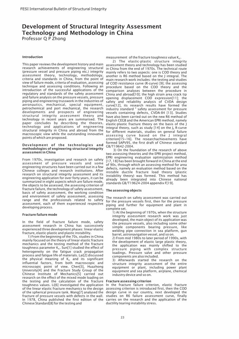
FESI International Bulletin of Structural Integrity
Introduction
Development of the technologies andmethodologies of engineering structural integrityassessment in China
Fracture failure mode
This paper reviews the development history and mainresearch achievements of engineering structural(pressure vessel and pressure piping etc.) integrityassessment theory, technology, methodology,criteria and standards in China, from the point ofview of failure mode, criteria of evaluation, assessingtechnique and assessing conditions. Following anintroduction of the successful applications of theregulatory and standards of the safety assessmentand failure analysis on the pressure vessels, pressurepiping and engineering trusswork in the industries ofaeronautics, mechanical, special equipment,petrochemical and port mechanical, the researchdevelopments and prospects of engineeringstructural integrity assessment theory andtechnology in recent years are summarised. Thepaper concludes by describing the theories,technology and applications of engineeringstructural integrity in China and abroad from themacroscopic view while the outstanding innovativepoints of which are proposed.
From 1970s, investigation and research on safetyassessment of pressure vessels and someengineering structures have been carried out in a fewChinese colleges and research institutions. Afterresearch on structural integrity assessment and itsengineering application for over forty years, it can besummarized in eight aspects which are failure mode,the objects to be assessed, the assessing criterion offracture failure, the technology of safety assessment,basis of safety assessment, the working conditionand environment of safety assessment, assessingrange and the professionals related to safetyassessment, each of them experienced respectivedeveloping process.
In the field of fracture failure mode, safetyassessment research in China has successivelyexperienced three development phases: linear elasticfracture, elastic-plastic and plastic instability.
1) From the beginning of the 70s, studies in Chinamainly focused on the theory of linear elastic fracturemechanics and the testing method of the fracturetoughness parameter K . Sun[1] studied the effect ofheterogeneity on the fatigue crack propagationprocess and fatigue life of materials. Lai[2] discussedthe physical meaning of K and its significantinfluential factors, from both macroscopic andmicroscopic point of view. Chen[3], HuazhongUniversity[4] and the Fracture Study Group of theChinese Institute of Mechanics[5] carried outresearch on the effect of the mixed mode loading onthe testing and the calculation of the fracturetoughness values. Li[6] investigated the applicationof the linear elastic fracture mechanics to the designof the spherical pressure tank. Wang[7] analysed thefracture of pressure vessels with defects in the wall.In 1978, China published the first edition of theChinese Standard[8] for the testing and
IC
IC
measurement of the fracture toughness value K .2) The elastic-plastic structure integrity
assessment theory and technology has been studiedin China from the end of 1970s. The technical routemainly refers to two aspects: one is COD theory andanother is R6 method based on the J integral. Themain research work includes: the testing and studiesof COD resistance curve (R-curve) [9]; the assessingprocedure based on the COD theory and thecomparison analyses between the procedure inChina and abroad[10]; the high strain area crack tipopening displacement COD expression[11]; thesafety and reliability analysis of CVDA designcurve[12], its research results have formed theindustry standard " safety assessment for pressurevessels containing defects, CVDA-84 [13]. Studieshave also been carried out on the new R6 method ofEnglish CEGB and the American EPRI method, namelyelastic-plastic fracture theory on the basis of the Jintegral theory, such as study [14] on the J R-curvefor different materials, studies on general failureassessing curve based on the J integralcriterion[15~16]. The researchachievements haveformed SAPV95, the first draft of Chinese standardGB/T19642-2004.
3) On the foundation of the research of abovetwo assessing theories and the EPRI project method,EPRI engineering evaluation optimization method[17, 18] has been brought forward in China at the endof 90s, through which an assessing method for areadefects, namely an evaluation method based on theinstable ductile fracture load theory (plasticinstability theory) was formed. This method hasalready been integrated into Chinese nationalstandards GB/T19624-2004 appendix F[19].
The research on safety assessment was carried outfor the pressure vessels first, then for the pressurepiping and further for equipment and plant incomplete set.
1) At the beginning of 1970s, when the structureintegrity assessment research work was justdeveloped, the main object of its application wasthe pressure vessels, also including some othersimple components bearing pressure, likewelding pipe connection in sea platform, gunbarrel, astronavigation vessel, and so on.2) From mid 1980s to later period of 1990s, withthe development of elastic large plastic theory,the application was mainly shifted to thepressure piping with complex structureloadings. Pressure valve and other pressurecomponents are also included.3) Afterwards started the research on thestructure integrity assessment of the entireequipment or plant, including power plantequipment and sea platform, airplane, chemicalindustry device and so on.
In the fracture failure criterion, elastic fractureassessing criterion is introduced first, then the CODdesign curve in our country, next developed thestudies on R6 failure assessment curve, finallycarries on the research and the application of theductility tearing instability stress.
IC
,
R
The assessing objects
Fracture assessing criterion
23
Development of Structural Integrity AssessmentTechnology and Methodology in ChinaProfessor Q P Zhong
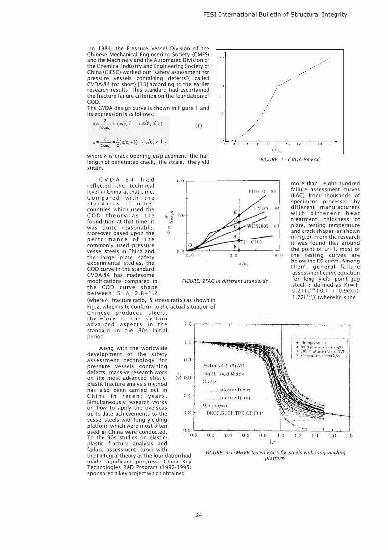
FESI International Bulletin of Structural Integrity
In 1984, the Pressure Vessel Division of theChinese Mechanical Engineering Society (CMES)and the Machinery and the Automated Division ofthe Chemical Industry and Engineering Society ofChina (CIESC) worked out “safety assessment forpressure vessels containing defects”( calledCVDA-84 for short) [13] according to the earlierresearch results. This standard had ascertainedthe fracture failure criterion on the foundation ofCOD.The CVDA design curve is shown in Figure 1 andits expression is as follows:
(1)
where is crack opening displacement, the halflength of penetrated crack, the strain, the yieldstrain.
C V D A - 8 4 h a dreflected the technicallevel in China at that time.C o m p a r e d w i t h t h es t a n d a r d s o f o t h e rcountries which used theCOD theo r y a s thefoundation at that time, itwas quite reasonable.Moreover based upon thepe r fo rmance o f thecommonly used pressurevessel steels in China andthe large plate safetyexperimental studies, theCOD curve in the standardCVDA-84 has madesomemodifications compared tothe COD curve shapebetween S = =0.8~1.2(where fracture ratio, S stress ratio ) as shown inFig.2, which is to conform to the actual situation ofChinese produced steels,therefore i t has certa inadvanced aspects in thestandard in the 80s initialperiod.
Along with the worldwidedevelopment of the safetyassessment technology forpressure vessels containingdefects, massive research workon the most advanced elastic-plastic fracture analysis methodhas also been carried out inC h i n a i n r e c e n t y e a r s .Simultaneously research workson how to apply the overseasup-to-date achievements to thevessel steels with long yieldingplatform which were most oftenused in China were conducted.To the 90s studies on elastic-plastic fracture analysis andfailure assessment curve withthe J integral theory as the foundation hadmade significant progress. China KeyTechnologies R&D Program (1992-1995)sponsored a key project which obtained
�
�
�r r
r r
more than eight hundredfailure assessment curves(FAC) from thousands ofspecimens processed bydifferent manufacturersw i t h d i f f e r e n t h e a ttreatment, thickness ofplate, testing temperatureand crack shapes (as shownin Fig.3). From the researchit was found that aroundthe point of Lr=1, most ofthe testing curves arebelow the R6 curve. Amongthem, general failureassessment curve equationfor long yield point jogsteel is defined as Kr=(1-0.211L )[0.1 + 0.9exp(-1.72L )] (where Kr is the
1.32
10.4r
r
FIGURE: 1 - CVDA-84 FAC
FIGURE: 2FAC in different standards
24
FIGURE: 3-15MnVR tested FACs for steels with long yieldingplatform
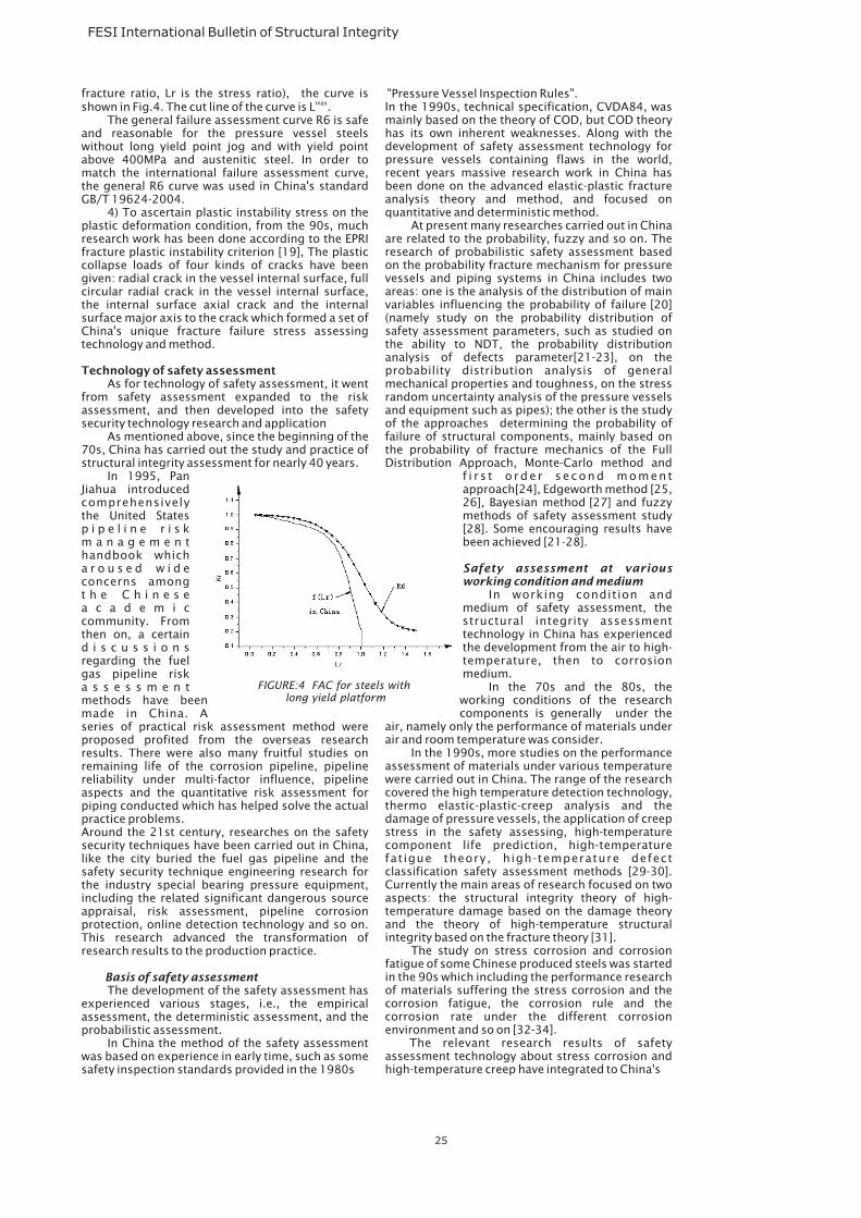
FESI International Bulletin of Structural Integrity
fracture ratio, Lr is the stress ratio), the curve isshown in Fig.4. The cut line of the curve is L .
The general failure assessment curve R6 is safeand reasonable for the pressure vessel steelswithout long yield point jog and with yield pointabove 400MPa and austenitic steel. In order tomatch the international failure assessment curve,the general R6 curve was used in China's standardGB/T 19624-2004.
4) To ascertain plastic instability stress on theplastic deformation condition, from the 90s, muchresearch work has been done according to the EPRIfracture plastic instability criterion [19], The plasticcollapse loads of four kinds of cracks have beengiven: radial crack in the vessel internal surface, fullcircular radial crack in the vessel internal surface,the internal surface axial crack and the internalsurface major axis to the crack which formed a set ofChina's unique fracture failure stress assessingtechnology and method.
As for technology of safety assessment, it wentfrom safety assessment expanded to the riskassessment, and then developed into the safetysecurity technology research and application
As mentioned above, since the beginning of the70s, China has carried out the study and practice ofstructural integrity assessment for nearly 40 years.
In 1995, PanJiahua introducedcomprehensivelythe United Statesp i p e l i n e r i s km a n a g e m e n thandbook whicha r o u s e d w i d econcerns amongt h e C h i n e s ea c a d e m i ccommunity. Fromthen on, a certaind i s c u s s i o n sregarding the fuelgas pipeline riska s s e s s m e n tmethods have beenmade in China. Aseries of practical risk assessment method wereproposed profited from the overseas researchresults. There were also many fruitful studies onremaining life of the corrosion pipeline, pipelinereliability under multi-factor influence, pipelineaspects and the quantitative risk assessment forpiping conducted which has helped solve the actualpractice problems.Around the 21st century, researches on the safetysecurity techniques have been carried out in China,like the city buried the fuel gas pipeline and thesafety security technique engineering research forthe industry special bearing pressure equipment,including the related significant dangerous sourceappraisal, risk assessment, pipeline corrosionprotection, online detection technology and so on.This research advanced the transformation ofresearch results to the production practice.
The development of the safety assessment hasexperienced various stages, i.e., the empiricalassessment, the deterministic assessment, and theprobabilistic assessment.
In China the method of the safety assessmentwas based on experience in early time, such as somesafety inspection standards provided in the 1980s
max
Technology of safety assessment
Basis of safety assessment
"Pressure Vessel Inspection Rules".In the 1990s, technical specification, CVDA84, wasmainly based on the theory of COD, but COD theoryhas its own inherent weaknesses. Along with thedevelopment of safety assessment technology forpressure vessels containing flaws in the world,recent years massive research work in China hasbeen done on the advanced elastic-plastic fractureanalysis theory and method, and focused onquantitative and deterministic method.
At present many researches carried out in Chinaare related to the probability, fuzzy and so on. Theresearch of probabilistic safety assessment basedon the probability fracture mechanism for pressurevessels and piping systems in China includes twoareas: one is the analysis of the distribution of mainvariables influencing the probability of failure [20](namely study on the probability distribution ofsafety assessment parameters, such as studied onthe ability to NDT, the probability distributionanalysis of defects parameter[21-23], on theprobability distribution analysis of generalmechanical properties and toughness, on the stressrandom uncertainty analysis of the pressure vesselsand equipment such as pipes); the other is the studyof the approaches determining the probability offailure of structural components, mainly based onthe probability of fracture mechanics of the FullDistribution Approach, Monte-Carlo method and
f i r s t o rde r second momentapproach[24], Edgeworth method [25,26], Bayesian method [27] and fuzzymethods of safety assessment study[28]. Some encouraging results havebeen achieved [21-28].
In working condition andmedium of safety assessment, thestructural integrity assessmenttechnology in China has experiencedthe development from the air to high-temperature, then to corrosionmedium.
In the 70s and the 80s, theworking conditions of the researchcomponents is generally under the
air, namely only the performance of materials underair and room temperature was consider.
In the 1990s, more studies on the performanceassessment of materials under various temperaturewere carried out in China. The range of the researchcovered the high temperature detection technology,thermo elastic-plastic-creep analysis and thedamage of pressure vessels, the application of creepstress in the safety assessing, high-temperaturecomponent life prediction, high-temperaturefatigue theory, high-temperature defectclassification safety assessment methods [29-30].Currently the main areas of research focused on twoaspects: the structural integrity theory of high-temperature damage based on the damage theoryand the theory of high-temperature structuralintegrity based on the fracture theory [31].
The study on stress corrosion and corrosionfatigue of some Chinese produced steels was startedin the 90s which including the performance researchof materials suffering the stress corrosion and thecorrosion fatigue, the corrosion rule and thecorrosion rate under the different corrosionenvironment and so on [32-34].
The relevant research results of safetyassessment technology about stress corrosion andhigh-temperature creep have integrated to China's
Safety assessment at variousworking condition and medium
25
FIGURE:4 FAC for steels withlong yield platform
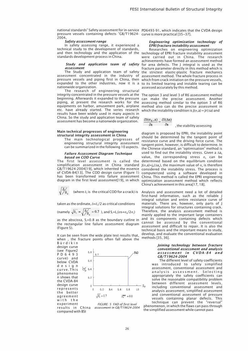
FESI International Bulletin of Structural Integrity
national standards” Safety assessment for in-servicepressure vessels containing defects ”GB/T19624-2004
In safety assessing range, it experienced atechnical study to the development of standards,and then technology and the application of thestandards development process in China.
The Study and application team of safetyassessment concentrated in the industry ofpressure vessels and piping first in China, thenexpanded to the other industries, now it is anationwide organization.
The research of engineering structuralintegrity concentrated in the pressure vessels at thebeginning. Afterwards it expanded to the pressurepiping, at present the research works for theequipments on harbor, amusement park, airplaneetc. have already started. The series researchresults have been widely used in many aspects inChina. So the study and application team of safetyassessment has become a nationwide organization.
The main technological progresses ofengineering structural integrity assessmentcan be summarized in the following 10 aspects.
The first level assessment is called thesimplification assessment in China standardGB/T19624-2004[19], which inherited the essenceof CVDA-84[13]. The COD design curve (Figure 1)has been transformed into failure assessmentdiagram in the first level assessment[19], in which
(where is the critical COD for a crack) is
taken as the ordinate, = /2 as critical conditions
(namely ), and S =L ( s+ /2 )
as the abscissa, S =0.8 as the boundary cutline inthe rectangular line failure assessment diagram(Figure 5).
It can be seen from the wide plate test results that,when , the fracture points often fall above theB ü r d i k i ndesign curve(see Figure2P D 6 4 9 3curve) andbelow CVDAd e s i g ncurve .Th isphenomenon shows thatthe CVDA-84design curverepresentsthe betteragreementw i t h t h eexperimentresults in Chinacompared with BSI
.Safety assessment range
Study and application team of safetyassessment
Failure Assessment Diagram Techniquebased on COD Curve
Main technical progresses of engineeringstructural integrity assessment in China
c
c
r r b s
r
�
� �
� � �
PD6493-91, which indicates that the CVDA designcurve is more practical [35~37].
Researches on engineering optimizationtechnology of EPRI fracture instability assessmentwere carried out in China. The researchachievements have formed an assessment methodfor area defects. The J integral is used as thefracture parameter directly in this method which isthe strictest elastic-plastic fracture mechanicsassessment method. The whole fracture process inwhich from crack initiation on the pressure vessels,to its limited tearing and instable tearing can beassessed accurately by this method.
The option 3 and level 3 of R6 assessment methodcan make the precise assessment. Anotherassessing method similar to the option 3 of R6method also can do the precise assessment inwhich the instability condition is J( ,a) = Jr( a) and
, the stability assessing
diagram is proposed by EPRI, the instability pointshould be determined by the tangent point ofresistance curve and the driving force curve. Thetangent point, however, is difficult to determine. Inthe Chinese standard, an “optimisation” method isused to find out the instability stress. Given a avalue, the corresponding stress can bedetermined based on the equilibrium conditionJ( ,a)=j ( a ), the maximum value of is thereforeconsidered the instability stress. The process iscomputerized using a software developed inChina. This method is called the EPRI engineeringoptimization assessment method which reflectsChina's achievement in this area[17, 18].
Analysis and assessment need a lot of detailedfirst-hand information, such as the reliable Jintegral solution and entire resistance curve ofmaterials. There are, however, only parts of Jintegral solutions for structures containing crack.Therefore, the analysis assessment method ismainly applied to the important large containersand its components containing defects whichcannot be assessed by the conventionalassessment and difficult to repair. It is also thetechnical basis and the important means to study,develop, and evaluate the conventional evaluationmethods [35, 36].
The different level of safety coefficientswas introduced to safety simplifiedassessment, conventional assessment anda n a l y s i s a s s e s s m e n t . S e l e c t i n gappropriately the safety coefficients cansolve the reasonable compatibility problembetween different assessment levels,including conventional assessment andanalysis assessment, simplified assessmentand conventional assessment of pressurevessels containing planar defects. Thistechnique can prevent the "reversal"
phenomenon, in which the flaws can pass throughthe simplified assessment while cannot pass
Engineering optimization technology ofEPRI fracture instability assessment
Joining technology between fractureconventional assessment and analysisassessment in CVDA-84 andGB/T19624-2004
� �
�
�
� � �
k
k
R k k
26
FIGURE: 5 FAD of first levelassessment in GB/T19624-2004
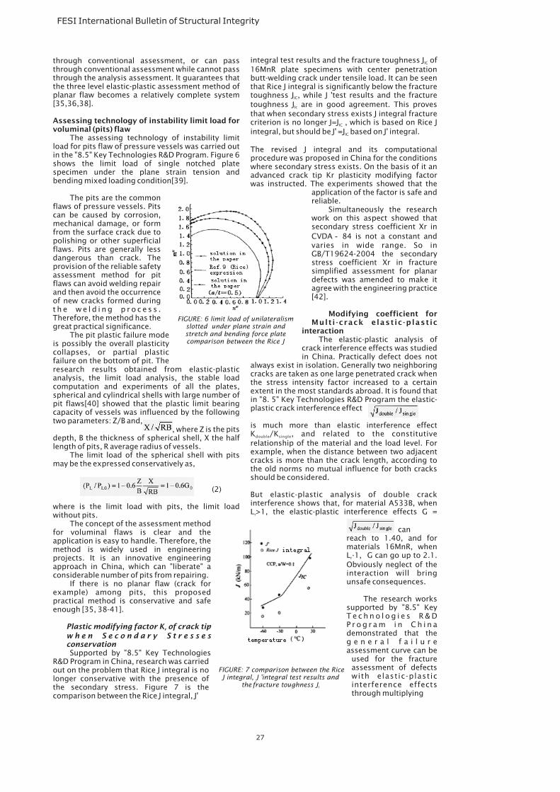
FESI International Bulletin of Structural Integrity
through conventional assessment, or can passthrough conventional assessment while cannot passthrough the analysis assessment. It guarantees thatthe three level elastic-plastic assessment method ofplanar flaw becomes a relatively complete system[35,36,38].
The assessing technology of instability limitload for pits flaw of pressure vessels was carried outin the "8.5" Key Technologies R&D Program. Figure 6shows the limit load of single notched platespecimen under the plane strain tension andbending mixed loading condition[39].
The pits are the commonflaws of pressure vessels. Pitscan be caused by corrosion,mechanical damage, or formfrom the surface crack due topolishing or other superficialflaws. Pits are generally lessdangerous than crack. Theprovision of the reliable safetyassessment method for pitflaws can avoid welding repairand then avoid the occurrenceof new cracks formed duringt h e w e l d i n g p r o c e s s .Therefore, the method has thegreat practical significance.
The pit plastic failure modeis possibly the overall plasticitycollapses, or partial plasticfailure on the bottom of pit. Theresearch results obtained from elastic-plasticanalysis, the limit load analysis, the stable loadcomputation and experiments of all the plates,spherical and cylindrical shells with large number ofpit flaws[40] showed that the plastic limit bearingcapacity of vessels was influenced by the followingtwo parameters: Z/B and,
, where Z is the pitsdepth, B the thickness of spherical shell, X the halflength of pits, R average radius of vessels.
The limit load of the spherical shell with pitsmay be the expressed conservatively as,
(2)
where is the limit load with pits, the limit loadwithout pits.
The concept of the assessment methodfor voluminal flaws is clear and theapplication is easy to handle. Therefore, themethod is widely used in engineeringprojects. It is an innovative engineeringapproach in China, which can "liberate" aconsiderable number of pits from repairing.
If there is no planar flaw (crack forexample) among pits, this proposedpractical method is conservative and safeenough [35, 38-41].
Supported by "8.5" Key TechnologiesR&D Program in China, research was carriedout on the problem that Rice J integral is nolonger conservative with the presence ofthe secondary stress. Figure 7 is thecomparison between the Rice J integral, J'
Assessing technology of instability limit load forvoluminal (pits) flaw
Plastic modifying factor K of crack tipw h e n S e c o n d a r y S t r e s s e sconservation
r
integral test results and the fracture toughness J of16MnR plate specimens with center penetrationbutt-welding crack under tensile load. It can be seenthat Rice J integral is significantly below the fracturetoughness J , while J 'test results and the fracturetoughness J are in good agreement. This provesthat when secondary stress exists J integral fracturecriterion is no longer J=J , which is based on Rice Jintegral, but should be J' =J based on J' integral.
The revised J integral and its computationalprocedure was proposed in China for the conditionswhere secondary stress exists. On the basis of it anadvanced crack tip Kr plasticity modifying factorwas instructed. The experiments showed that the
application of the factor is safe andreliable.
Simultaneously the researchwork on this aspect showed thatsecondary stress coefficient Xr inCVDA 84 is not a constant andvaries in wide range. So inGB/T19624-2004 the secondarystress coefficient Xr in fracturesimplified assessment for planardefects was amended to make itagree with the engineering practice[42].
The elastic-plastic analysis ofcrack interference effects was studiedin China. Practically defect does not
always exist in isolation. Generally two neighboringcracks are taken as one large penetrated crack whenthe stress intensity factor increased to a certainextent in the most standards abroad. It is found thatin "8. 5" Key Technologies R&D Program the elastic-plastic crack interference effect
is much more than elastic interference effectK /K , and related to the constitutiverelationship of the material and the load level. Forexample, when the distance between two adjacentcracks is more than the crack length, according tothe old norms no mutual influence for both cracksshould be considered.
But elastic-plastic analysis of double crackinterference shows that, for material A533B, whenL >1, the elastic-plastic interference effects G =
canreach to 1.40, and formaterials 16MnR, whenL -1, G can go up to 2.1.Obviously neglect of theinteraction will bringunsafe consequences.
The research workssupported by "8.5" KeyT e c h n o l o g i e s R & DP r o g r a m i n C h i n ademonstrated that theg e n e r a l f a i l u r eassessment curve can be
used for the fractureassessment of defectswith elastic-plasticinterference effectsthrough multiplying
IC
IC
Ic
IC
IC
double single
r
r
-
Modifying coefficient forMult i -crack elast ic -plast ic
interaction
FIGURE: 6 limit load of unilateralismslotted under plane strain andstretch and bending force platecomparison between the Rice J
27
FIGURE: 7 comparison between the RiceJ integral, J 'integral test results and
the fracture toughness JI
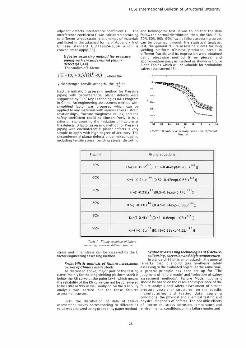
FESI International Bulletin of Structural Integrity
adjacent defects interference coefficient G. Theinterference coefficient G was calculated accordingto different stress-strain relationships of materialsand listed in the attached forms of Appendix A ofChinese standard GB/T19624-2004 which isconvenient to apply [35].
The studies of U factor
, where the
yield strength, tensile strength, the at
fracture initiation) assessing method for Pressurepiping with circumferential planar defects weresupported by “9.5" Key Technologies R&D Programin China. An engineering assessment method withsimplified factor was proposed which can beapplied to any materials with various stress - strainrelationships, fracture toughness values, and thesafety coefficient could be chosen freely. It is acriterion representing the initiation of fracture atthe defects. U factor assessing method for Pressurepiping with circumferential planar defects is verysimple to apply with high degree of accuracy. Thecircumferential planar defects under mixed loadingincluding tensile stress, bending stress, distorting
stress and inner stress can be assessed by the Ufactor engineering assessing method.
As discussed above, major part of the testingcurve (mainly for the long yielding platform steel) isbelow the R6 curve at the point Lr=1, which meansthe reliability of the R6 curve can not be consideredto be 100% or 99% as we usually do. So the reliabilityanalysis was carried out for these failuresassessment curves.
First, the distribution of data of failureassessment curves corresponding to different Lrvalue was analyzed using probability paper method
U factor assessing method for pressurepiping with circumferential planardefects[43,44]
Probabilistic analysis of failure assessmentcurves of Chinese made steels
(
and Kolmogorov test. It was found that the datafollow the normal distribution; then, the 50%, 60%,70%, 80%, 90%, 99% fractile failure assessing curvescan be obtained through the statistical analysis;last, the general failure assessing curves for longyielding platform (Chinese produced) steels indifferent fractile and its expression were obtainedusing piecewise method (three pieces) andapproximation analysis method as shown in Figure8 and Table1 which will be valuable for probabilitysafety assessment[45].
In standard [19], it is emphasized in the generalremarks that it should take Synthesis safetyassessing to the evaluated object. At the same time,a general principle has been set up for "Thejudgment of failure mode" and "selection of safetyassessment methods". Failure Mode judgmentshould be based on the cases and experience of thefailure analysis and safety assessment of similarpressure vessels or structures, on the specificmanufacturing and testing data, applyingconditions, the physical and chemical testing andphysical diagnosis of defects. The possible effectsof corrosion, stress corrosion, temperature andenvironmental conditions on the failure modes and
Synthesis assessing technologies of fracture,collapsing, corrosion and high temperature
28
Table 1 - Fitting equations of failureassessing curves on different fractile
FIGURE: 8 Failure assessing curves on differentfractile
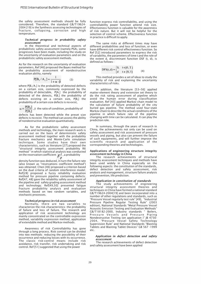
FESI International Bulletin of Structural Integrity
the safety assessment methods should be fullyconsidered. Therefore, the standard GB/T19624-2004 [19] is the Synthesis assessing technologies offracture, collapsing, corrosion and hightemperature.
In the theoretical and technical aspects ofprobabilistic safety assessment (namely PSA), someprogresses have been made, including the study onthe uncertainty of evaluation parameters and on theprobabilistic safety assessment methods.
As for the research on the uncertainty of evaluationparameters, Ref [46] proposed the Bayes method forthe probability assessment of nondestructiveevaluation ability, namely
(3)
where P[B /A ] is the probability of detected defectson a certain size, commonly expressed by theprobability of detectable, P[A ] the probability ofdetected of the detects, P[B ] the probability ofdefects existing on a certain size, P[B ] theprobability of a certain size defects is no exist,
, the ratio of condition, probability of
defects has been detected while the preset sizedefects is no exist. The method can assess the abilityof nondestructive evaluation quantitatively.
As for the probabilistic safety assessmentmethods and technology, the main research work iscarried out on the basis of deterministic safetyassessment method together with the probabilityfracture mechanics and Monte-Carlo simulationtechnique. Some studies have their owncharacteristics, such as literature [27] proposed the"structural integrity assessment probability R6method " in which statistical analysis was conductedon the reservation coefficient , a probability
density function was deduced, in turn the failure rate(also known as "reservations coefficient method")was obtained; Chen [46] proposed a criterion basedon the dual criteria of random interference model;Ref[28] proposed a fuzzy reliability evaluationmethod for pressure pipeline containing defects;Ref[47, 48] gave the reliability safety assessment ofthe pipeline and safety grading assessment methodand technology; Ref[49,50] presented fatiguefracture probability analysis and evaluationmethods based on two random variables, andstochastic processes.
Normally, there are two variables tocharacterize the risk characteristics: the probabilityof failure and loss of failure. The research andapplication of risk assessment technology aremainly concentrated on the controllable expressionmethod, variability expression method, applicationof extendable method and Markov methods.
Awareness of risk Controllability has gonethrough a long process. Risk control can be dividedinto two methods: reducing the possibility of theiroccurrence and reducing losses with its occurrence.The classic risk-control means include riskavoidance, risk transfer, risk undertaking and riskcontrol. Ref [51] suggested that using the power
Technical progress in probability safetyassessment
Technical progress in risk assessment
1 1
1
1
2
�
function express risk controllability, and using thecontrollability power function amend risk size.Effectiveness function is valuable for the awarenessof risk nature. But it will not be helpful for theselection of control scheme. Effectiveness functionin practice is difficult to apply.
The same risks at different times may havedifferent probabilities and loss of function, or evenhave different risk control effectiveness function. SoRef [52] introduced parameters to express the riskof variability, the parameters of time t and the role ofthe extent d, discriminant function DSF (t, d), isdefined as follows :
(4)
This method provides a set of ideas to study thevariability of risk and explaining the uncertaintycharacteristics of risks.
In addition, the literature [53~56] appliedmatter-element theory and extension set theory todo the risk rating assessment of pipeline whichavoid the human error during classificationevaluation. Ref [43] applied Markov chain model tothe calculation of failure probability of the cityburied gas pipeline. The method used four-stateMarkov chain to describe the actual conditions of thepipeline in which failure rate of the pipelinechanging with time can be calculated. It can play theprediction role.
In summary, through the years of research inChina, the achievements not only can be used onsafety assessment and risk assessment of pressurevessels and piping, but also can prevent the failureof such equipments, and will further improve thescientific research and application of thecorresponding theories and technologies.
The research achievements of structuralintegrity assessment techniques and methods havebeen used widely in China especially on thefollowing aspects: the constitution of the standards,defect detection and safety assessment, riskanalysis and management, structure failure analysisand prevention, life prediction.
The study achievements of engineeringstructural integrity assessment theories andtechniques in China have formed a national standardGB/T19624-2004[19] and been incorporated into anumber of other regulations and standards, such as“Pressure Vessel regularly test rule” [49], “IndustrialPressure Pipeline Regular Testing Rule” (2003edition), National Standards “Metal Pressure VesselAcoustic Emission Testing and Evaluation Methods”GB/T18182-2000, Industry standards “ Boilers,P ressure Vesse l s and Pressure P ip ingNondestructive Testing (on application )” JB 4730-2004, “Pressure Vessel Safety TechnologySupervision Rule” and National Standards “BlastingTablets and Blasting Tablet Devices” GB 567 -1999etc.
The research achievements of defect detectionand safety assessment have been applied
Applications of engineering structure integrityassessment technolgy in China
Application in constitution of standards
Application in defect detection and safetyassessment
29
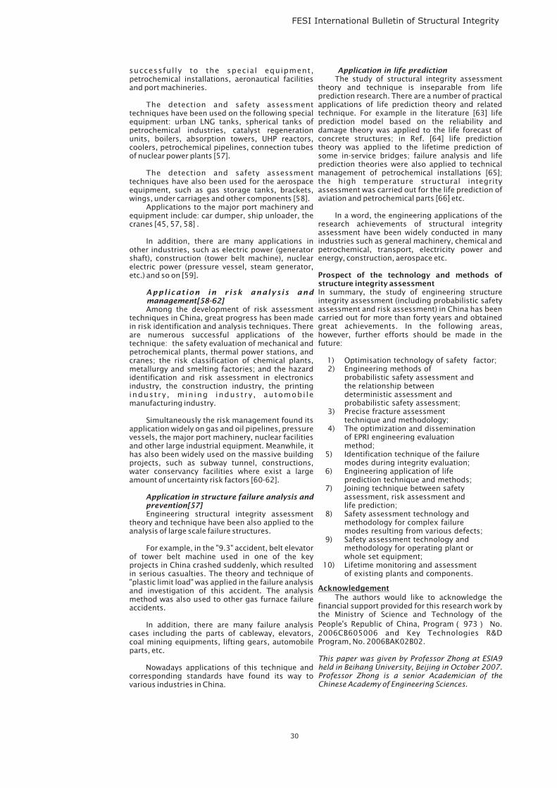
FESI International Bulletin of Structural Integrity
successful ly to the special equipment,petrochemical installations, aeronautical facilitiesand port machineries.
The detection and safety assessmenttechniques have been used on the following specialequipment: urban LNG tanks, spherical tanks ofpetrochemical industries, catalyst regenerationunits, boilers, absorption towers, UHP reactors,coolers, petrochemical pipelines, connection tubesof nuclear power plants [57].
The detection and safety assessmenttechniques have also been used for the aerospaceequipment, such as gas storage tanks, brackets,wings, under carriages and other components [58].
Applications to the major port machinery andequipment include: car dumper, ship unloader, thecranes [45, 57, 58] .
In addition, there are many applications inother industries, such as electric power (generatorshaft), construction (tower belt machine), nuclearelectric power (pressure vessel, steam generator,etc.) and so on [59].
Among the development of risk assessmenttechniques in China, great progress has been madein risk identification and analysis techniques. Thereare numerous successful applications of thetechnique: the safety evaluation of mechanical andpetrochemical plants, thermal power stations, andcranes; the risk classification of chemical plants,metallurgy and smelting factories; and the hazardidentification and risk assessment in electronicsindustry, the construction industry, the printingindustry , min ing industry , automobi lemanufacturing industry.
Simultaneously the risk management found itsapplication widely on gas and oil pipelines, pressurevessels, the major port machinery, nuclear facilitiesand other large industrial equipment. Meanwhile, ithas also been widely used on the massive buildingprojects, such as subway tunnel, constructions,water conservancy facilities where exist a largeamount of uncertainty risk factors [60-62].
Engineering structural integrity assessmenttheory and technique have been also applied to theanalysis of large scale failure structures.
For example, in the "9.3" accident, belt elevatorof tower belt machine used in one of the keyprojects in China crashed suddenly, which resultedin serious casualties. The theory and technique of"plastic limit load" was applied in the failure analysisand investigation of this accident. The analysismethod was also used to other gas furnace failureaccidents.
In addition, there are many failure analysiscases including the parts of cableway, elevators,coal mining equipments, lifting gears, automobileparts, etc.
Nowadays applications of this technique andcorresponding standards have found its way tovarious industries in China.
Appl icat ion in r isk analys is andmanagement[58-62]
Application in structure failure analysis andprevention[57]
Application in life predictionThe study of structural integrity assessment
theory and technique is inseparable from lifeprediction research. There are a number of practicalapplications of life prediction theory and relatedtechnique. For example in the literature [63] lifeprediction model based on the reliability anddamage theory was applied to the life forecast ofconcrete structures; in Ref. [64] life predictiontheory was applied to the lifetime prediction ofsome in-service bridges; failure analysis and lifeprediction theories were also applied to technicalmanagement of petrochemical installations [65];the high temperature structural integrityassessment was carried out for the life prediction ofaviation and petrochemical parts [66] etc.
In a word, the engineering applications of theresearch achievements of structural integrityassessment have been widely conducted in manyindustries such as general machinery, chemical andpetrochemical, transport, electricity power andenergy, construction, aerospace etc.
In summary, the study of engineering structureintegrity assessment (including probabilistic safetyassessment and risk assessment) in China has beencarried out for more than forty years and obtainedgreat achievements. In the following areas,however, further efforts should be made in thefuture:
1) Optimisation technology of safety factor;2) Engineering methods of
probabilistic safety assessment andthe relationship betweendeterministic assessment andprobabilistic safety assessment;
3) Precise fracture assessmenttechnique and methodology;
4) The optimization and disseminationof EPRI engineering evaluationmethod;
5) Identification technique of the failuremodes during integrity evaluation;
6) Engineering application of lifeprediction technique and methods;
7) Joining technique between safetyassessment, risk assessment andlife prediction;
8) Safety assessment technology andmethodology for complex failuremodes resulting from various defects;
9) Safety assessment technology andmethodology for operating plant orwhole set equipment;
10) Lifetime monitoring and assessmentof existing plants and components.
The authors would like to acknowledge thefinancial support provided for this research work bythe Ministry of Science and Technology of thePeople's Republic of China, Program 973 No.2006CB605006 and Key Technologies R&DProgram, No. 2006BAK02B02.
Prospect of the technology and methods ofstructure integrity assessment
Acknowledgement
( )
This paper was given by Professor Zhong at ESIA9held in Beihang University, Beijing in October 2007.Professor Zhong is a senior Academician of theChinese Academy of Engineering Sciences.
30
FESI International Bulletin of Structural Integrity
Reference list
(1) Sun X . , Ac ta Mechan i ca S in i ca , Vo l .10 ,No.2,1978,pp167-170.
(2) Lai Z., J. of Northeastern University(Natural Science),1979, No. 01, pp1-17.
(3) Chen Ch., Acta Mechanica Sinica, Vol.6, No.3,1974,pp121-124.
(4) HuaZhong Institute of Technology Fracture StudyGroup, J. of Mechanical Strength, 1978, No.4, pp4758
(5) Fracture Study Group ,Institute of Mechanics of TheChinese Academy of Sciences, Acta Mechanica Sinica,Vol.8, No.3,1976 pp168 173.
(6) Li Zh., Industrial Construction, 1979, No.4,pp45-49.(7) Wang R., Fluid Machinery,1977, No.8, pp20 31.(8) Fracture Toughness KIC Testing standard of Metal
material under plane strain, Metallurgical Ministry,YB947-78,1980, Beijing.
(9) Li, Z., Zeng, G., Peng, N., J. Chemical Industry and Eng.Vol.38, No. 2, 1987, pp156-164
(10) Liu, Z., J. Zhengzhou University of Light Industry, Vol.4,No. 4, 1991,pp44-48.
(11) Li, Z., Solomos,G., Lucia, A.,etl. J. Pressure Vessle,Vol.6, No. 5, 1993,pp33-37.
(12) Zhou, Z., Liu, C., J. Taiyuan University of Sci. & Tech.,Vol.11, No. 4, 1990,pp1-11.
(13) National Standard, Safety assessment Criterion ofpressure vessel containing defect (CVDA-84), 1984.
(14) Wang, Y., Jiang, Zh., Research on the R-curve test ofseveral Pressure Vessel Steel,1993,11.
(15) Wang,W., Engineering Method of gap elasticplasticfracture analysis, Doctor Dissertation of East ChinaUniversity Of Science And Technology, Shanghai, 1989.
(16) Wang, Zh.,Li P., Lei, Y., Research on General FAC ofPressure Vessels in China, Pressure Vessel and PipingIntegrity Technology, Mechanical Industry Publishing,Beijing, China,2006.
(17) Fei, Y., Dong, Y., Huang, K., Consistency Research oftwo mode of ductility fracture assessment of FAC basedon in PD6493 and EPRI, Proceedings of Third Chinastructure Engineering Academic Conference,engineering machenics,supplement 1994.
(18) Fei, Y., Cai, G., Dong, Y., Engineering Mechanics,Vol.12, No.4,1995,pp115-122.
(19) National Standard, Safety assessment for in-servicepressure vessels containing defects (GB/T 19624-2004), 2004.
(20) Wang, W., Chen, G., Xu. F., Oil Ore yard Mechinary,Vol.24 No.6,1995, pp21-24.
(21) Chen, G., Physical and Chemical Inspection, Vol.36No.8, 2000,pp339-341.
(22) He, B., Yu, Y., Huo, L., Pressure Vessel Technolgy,Vol.20 No.11,2003,pp16-24.
(23) Xiong, J., Peng, J., Gao, Zh., J Beijng Aero. &Astro.,Vol.26 No.6,2000,pp694-696.
(24) Liu,Ch., Lin, Y., J Jiamusi University, Vol.17,No.1999,pp30-33.
(25) Yan, X.,Xie, Y., Dai, Y., Mechanical Design andManufacture, Vol.12 No.1,2004,pp6-8.
(26) Chen, G., Dai, Sh., Calculation Program and itEngineering Application of Probability safetyassessment, J Najing Aero. &Astro., Vol.31No.3,1999,pp346-350.
(27) Wu, H., Research on the Structure Integrity ProbabilityR6 assessing Method, Doctor Dissertation, BeijingUniversity of Aero. &Astro.,1996.
(28) Zhu, L., Research on the fuzzy assessing method for inservice pressure piping containing defects, DoctorDissertation, Nanjing University of Aero. &Astro.,2000.
(29) Wang, Ch., Tang, Y., Damage Calculation and thermoelasticplastic creep deformation of pressure vessel,Proceedings of Third China structure EngineeringAcademic Conference.
(30) Qi, Y., Wang, H., Wu D., Research on residual lifeprediction of high temprature components,Proceedings of Third China structure EngineeringAcademic Conference.
(31 )Tu, Sh., Xuan F., Structure Integrity technology of hightemperature bearing components, Proceedings of SixthChina structure Engineering Academic Conference .
(32) Yao, X., Research on the scc and corrosion fatigueperformance of 07MnCrMoV Steel, Proceedings ofFourth China structure Engineering AcademicConference.
-
, -
-
,
,
,
,
,
,
,
(33) Dong, J., SCC fracture of resistance weld pipe soakingin mix nitrite solution, Proceedings of Fourth Chinastructure Engineering Academic Conference.
(34) Yuan, J., Investigation on the corrosion rate of gaspipes, Proceedings of Fifth China structure EngineeringAcademic Conference.
(35) Zhong, Q., Li, P., Li, X.,etl, Oil and Gas Storage andTransportation, 2005, pp138~146.
(36) Li, P., Comprehensive Safety assessment and safetyGrade assessment, Report No. 05-01-04-05,1995
(37) Zhong, Q., SPV95 conventional assessment results"reversed" the probability analysis and surface cracksassessment calculation, Report No. 05-01-04-05,1995
(38) Yan, H., Hu, Zh., Li, P., Pressure vessel technology, Vol.No. 199 pp15-19
(39) Guo, P., Hu, H., Li P., J. Shanghai University (NaturalScience), Vol.3.No.5, 1997, pp492-499.
(40) Chen, G., Liu, Y., Structure plastic limit numericalmethod and engineering application, pressure vesseland piping integrity assessing technology, MechanicalIndustry Publishing , 2006 pp88-103.
(41) Liu, Y., Chen, Zh., Xu, B., Acta Mechanical SolidaSinica,Vol.20 No.3 1999, pp211-218.
(42) Cui, F., Wang, Zh., Ju,D., etl , Engineering Mechanics,Vol.14, No.2 1997, pp90-95.
(43) Xu, H., Li, P.,Engineering Safety Assessment Procedurefor Preventing Fracture Initiation of Piping Flaws,Petrochemical equipment Vol.24 No.3, pp14-18.
(44) Li P., Liu Ch., Pressure vessel Techonlogy, Vol.18, No.6,2001,pp1-7.
(45) Luo, H., Zhang, Y., J Beijing University of Aero&Astro,Vol. 32 No.14 2006,pp450 454.
(46) Chen, G., PSA Engineering method of welding structurecontaining defects based on the double Criterion,Doctor Dissertation, Nanjing Chemical IndustryUniversity,1996.
(47) Zuo, Sh., Study on Reliability Safety Assessment andSafety Grade Assessment Technology for In-ServicePressure Pipe ,Doctor Dissertation, Beijing University ofAero&Astro,1999.
(48) Zuo, Sh., Zhong, Q., Wu, H., Zhang, Zh., MechanicalStrength, Vol.22 No.1,2000,pp69-71.
(49) Jin, X., Engineering fracture failure probability analysisand assessing method, Doctor Dissertation, BeijingUniversity of Aero&Astro,1998.
(50) Zhong, Q., Jin, X., Hong, Y., etl, Probability analysis andassessment of fracture failure, Beijing University ofAero.&Astro. Publishing, Beijing, China, 2000.
(51) Zhang, J., Zhong, D., J Luoyang University, Vol.17, No.22002, pp 48-53.
(52) Zhu, K., J System Engineering Theory and Practice,No.11, 2003, pp 42-46.(53) Sun, Y., Researchon the Risk assessment of city buried gas piping,Doctor Dissertation, Beijing University of Aero&Astro,2005
(54) Zhang, Y., Research on the Engineering Riskassessment. Doctor Dissertation, Nanjing, NanjingIndustry University, 2002.
(55) Jia., S., Liao, J., Zhou, Zh. J. Chongqing JiaotongInstitute, Vol.25 No.2,2006,pp125-131.
(56) National Standard, Period Inspection rule of Pressurevessel, 2004.
(57) Chen G., Li P., Chen X., Integrity Technology forPressure Vessel and Pressure Pipeline, China MachinePress, Beijing, 2006, pp3-25.
(58) Wu, Zh., Gao, J., Zhang, X., Industry hazardidentification and assessment, Weather Publishing,Beijing,2000.
(59) Li, Zh., Hazard identification and risk assessment in tenIndustry, Chinese Standard Publishing, Beijing, 2006.
(60) Zhang, L. ,Zhang J.,Architecture construction, Vol.28,No.3,2006,pp177-179.
(61) Li, W., Zhang, M., Building Technique development,Vol.31, No.9,2004, pp 144-145.
(62) Chen, J., Huang, W., Cheng, W., Engineering Applicationof risk on irrigation, Beijing, Changjiang Publishing,2006.
(63) Miao, Ch., Sun, W., Guan, Y., J Silicate, Vol.29, No.6,2001, pp 535-540.
(64) Wang, J., Reliability analysis and life prediction of inservice Bridge inspection, Chinese hydraulic andelectric publishing, 2006.
(65) Tan, Y., Wang, L., Zhao, J., Engineering Example of Lifeprediction and failure analysis of Petrifaction devices,Beijing: Chemical Industry Publishing, 2007.
(66) Chen, X., Yang, D., Lou, Y., etl, J. Zhejiang ElectricPower, Vol.24,No.2,2005, pp47-50.48)Zuo, Sh.,Zhong, Q., Wu, H., Zhang, Zh., Mechanical Strength,Vol.22 No.1,2000,pp69-71.
,
,
, ~
,
,
31
FESI International Bulletin of Structural Integrity
Conferences/Seminars cont.
Courses Information
7th International Conference on ModernPractice in Stress and Vibration Analysis
12th International Conference on PressureVessel Technology
5th International Conference on Creep, Fatigueand Creep-Fatigue Interaction
Cambridge8-10 September 2009
Korea20-23 September 2009
India24-26 September 2009
Modern Metal Fatigue Analysis Class
High Temperature Component LifeAssessment
Residual Stress Measurement Workshop
Imech E Events
The Pump Centre, ESR Technology.
www.pumpcentre.com/training.htm
European Technology Development Ltd
www.etd1.co.uk
Engineering Integrity Society Courses
For details:
www.e-i-s.org.uk
FESI co-sponsrs a number of ImechE events.
For more information:
and search for s1425, s1309, c672
Wide range of courses on all engineering aspects
of pumps and pumping systems, including failure
analysis, condition monitoring and tribology.
For more information:
Offers training courses in the areas of:
Defect/crack assessment, structural stress
analysis, plant remaining life assessment and life
extension, etc.
For more information:
Optimising automotive components for cost,
weight and fatigue durability using residual strain
and damage measurements to improve CAE
models
For more information:
www.mpsva2009.org
www.icpvt12.org & [email protected]
www.igcar.gov.in/seminars/cf5
Nuneaton, UK13 April 2009For more information:[email protected]
Imperial College, London27- 29 May 2009For more information:[email protected]
Bristol University,22 25 September 2009For more information: www.veqter.co.uk/events
www.imeche.org/events
EMAS Publishing is a small publishing company wholly owned by FESI - UK Forum for Engineering Structural Integrity. It
specialises in engineering research and academic technical publications, and it is our aim to provide a cost effective yet
bespoke publishing tool. We support Technical Conference organisers by publishing their proceedings. We will organise
post conference publications, through the publication of Notable Technical Papers (NTPs). We will advise technical
authors who wish to publish a text book. Dedicated specialist Journals, such as the FESI International Bulletin on
Structural Integrity, will provide new technical writers the opportunity to get into print. See [email protected]
Forthcoming Worldwide Events
Conferences/Seminars
EMPA
NAFEMS World Congress 2009
Welds 2009
Mesomechanics 2009
ICONE 17
ICF 12
ASME PVP Conference
SMiRT 20
14 International Conference on EnvironmentalDegradation of Materials in Nuclear Power
Operating Pressure Equipment, incorporatingAINDT
High Temperature Conference - Creep & Fracture inHigh Temperature Components - Design & LifeAssessment Issues21-23 April 2009Zurich, Switzerlandwww.etd1.co.uk
Heraklion on Crete, Greece.16-19 June 2009www.nafems.org/congresse-mail abstract to
Design, testing, assessment and safety of hightemperature welded structuresEPRI & VAMAS,USA24-26 June 2009
Dissipation and damage across multiple scales inphysical and mechanical systemsOxford24-26 June 2009
17th International Conference on NuclearEngineeringBrussels, Belgium12-16 July 2009
12th International Conference on FractureOttawa, Canada12-17 July 2009
Prague26-30 July 2009
Challenges facing Nuclear Renaissance focusing toinnovative and practical solutions in the planning,design, construction and operation of NPPs andother nuclear facilitiesHelsinki, Finland9 -14 August 2009www.vtt.fi/smirt20
Systems-Water ReactorsVirginia Beach, USA24-27 August 2009
Queensland, Australia26-28 August 2009
www.meso2009.com
www.asmeconferences.org/icone17/ coveringStructural integrity
www.icf12.org
www.asmeconferences.org
www.materialsaustralia.com.au/OPE09