Embed Size (px)
Citation preview
IAEG2006 Paper number 107
© The Geological Society of London 2006 1
The Farr Windfarm: site investigation for an ecologically sensitiveinfrastructure project
DAVID CARPENTER,1 PETER O’CONNOR2 & LAURENCE DONNELLY3
1 APEX Geoservices Ltd, Mill House, High Street, Melbourne Derby DE73 8GJ, UK.([email protected])
2 APEX Geoservices Ltd, Kilanerin, Gorey, Co. Wexford, Ireland. ([email protected])3 Halcrow Group Ltd, Deanway Technology Centre, Wilmslow Road, Handforth, Cheshire, SK9 3FB, United
Kingdom ([email protected])
Abstract: The continuing growth of urban areas inevitably leads to additional pressures, to develop supportinginfrastructure, in the rural landscapes which surround them. Quite often, these regions are areas of outstandingnatural beauty, ecologically sensitive sites or sites of special scientific interest. This requires the careful designand implementation of site investigations. This is necessary to guarantee the future sustainability of theseresources without irreparably damaging their character. A programme of geophysical and geotechnical groundinvestigation work was carried out for a 40 turbine wind farm in a remote, upland area of the ScottishHighlands, dominated by moorland vegetation, and peat. The ground investigations were designed to providerelevant data and to gain a conceptual understanding of the geology, the near-surface geotechnicalcharacteristics, geohazards, hydrogeology and ground conditions at, and in the vicinity of, each turbine base,and associated infrastructure. It was a requirement of the investigation to cause minimum environmental impacton the ecologically sensitive moorland. The project comprised of a desk study, non-invasive geophysicalsurveys including: ground penetrating radar, 2D resistivity imaging and seismic refraction. This was verified byan invasive drilling and trial pitting programme, including sampling and laboratory testing. The primaryobjectives of the ground investigation were to determine the depth of surface peat cover, thickness of sub-peatglacial deposits, and thickness and competency of the underlying weathered and fresh metamorphic bedrock.One of the most significant issues in carrying out the project was the logistics of transporting the necessaryequipment and field crews from the base camp to each individual survey site across a difficult landscape,dominated by peat and bogs, of over 25 square kilometres, with elevations over 750 m AOD whilst maintainingan efficient production rate. The objectives of this paper are to document and draw attention to this groundinvestigation, in an ecologically sensitive environment. This paper describes the various technical and logisticalproblems and how they were overcome to provide geophysical, geological and geotechnical information whichprovided the basis for underpinning the engineering design of the wind turbine bases.
Résumé: La croissance continue des secteurs urbains mène inévitablement aux pressions additionnelles pourdévelopper infrastructure de support dans les secteurs ruraux qui les entourent. Souvent, ces régions sont debeauté naturelle exceptionnelle, des emplacements écologiquement sensibles ou des emplacements d'intérêtscientifique spécial. Ceci exige la conception et l'exécution soigneuse des investigations d'emplacement. Ceciest nécessaire pour garantir la future durabilité de ces ressources sans endommager irréparablement leurcaractère. Un programme de travail de recherche au sol géophysique et géotechnique a été effectué pour uneferme de vent de 40 turbines dans une région éloignée dans les montagnes écossaises dominé par la végétationde bruyère et la tourbe. Les investigations d'emplacement ont été conçues pour fournir des données appropriéeset pour gagner un arrangement conceptuel de la géologie et des caractéristiques géotechniques, del'hydrogéologie et des conditions du sol à et à proximité de chaque base de turbine et l’infrastructure associée.C'était une condition de la recherche de causer un minimum des incidences sur la bruyère écologiquementsensible. Le projet consisté en une étude de bureau et aperçus géophysiques non envahissants comprenant radarpénétrant, réfraction séismique, formation d’une image de résistivité. Ceci a été vérifié par un programme deforage invahissant et des puits d’épreuve, incluant prélèvement et essais en laboratoire. Les premiers objectifsde la recherche au sol étaient la détermination de la profondeur de la couverture extérieure de tourbe,l’épaisseur des gisements glaciaires sous la tourbe et l’épaisseur et compétence de la roche survécue etmétamorphique fondamentale. Une des problèmes les plus significatives en mettant le projet était la logistiquede transporter l'équipement nécessaire et les équipes de champ du camp de base à chaque emplacementd'aperçu à travers un paysage difficile, dominé par des marais de tourbe, de plus de 25 kilomètres carrés avecdes altitudes de plus de 750m tout en maintenant un taux efficace de production. Les objectifs de cet articlesont de documenter et d’appeler l'attention sur cette recherche au sol dans un environnement écologiquementsensible. Cet article décrit les divers problèmes techniques et logistiques et comment ils ont été surmontés pourfournir l'information géophysique, géologique et géotechnique qui ont fourni la base pour soutenir laconception de technologie de la base des turbines de vent.
Key words: environmental impact, site investigation, geophysics, geotechnical engineering, ecology,engineering geology
IAEG2006 Paper number 107
2
INTRODUCTIONOn 28 February 2003 the Highland Council decided not to object to the development of a major Wind Farm at Farr,
near the village of Tomatin, Inverness-shire. The project was subsequently approved by the Scottish Executive on 5October 2004, when the Deputy Enterprise Minister, Allan Wilson, stated that the project would bring the totalelectricity generated from renewable resources in Scotland to 18%.
The Project had first been proposed in 1996, with an initial plan to generate 112.5 MW of power. The approvedplan called for 40 turbine bases generating 92 MW of power, or enough to provide electricity to 53,400 homes, with acarbon emissions saving of 215,900 tonnes over the planned 20-25 year life of the facility.
Farr was chosen for development because of its remoteness from dwellings, the minimum visual impact affordedby the bowl-shaped interior of site, and the particularly high average wind speed recorded at the site. However, thecharacteristics which make the site ideal for the development of a wind farm make the site logistically difficult for asite investigation project.
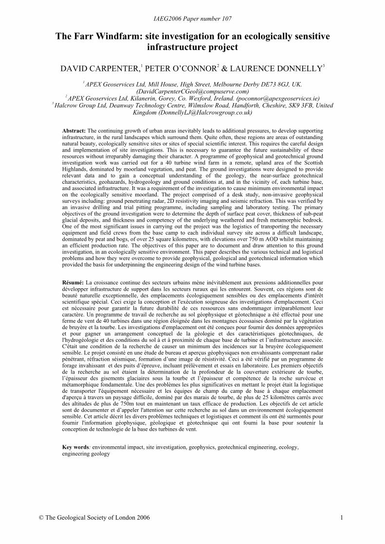
With an average elevation in excess of 500m AOD, in a landscape of peat moorland incised by numerous smallwater courses, the site is in one of the most inhospitable areas of the British Isles. Also, the ecologically sensitivenature of the site necessitated a particularly careful approach to the movement of vehicles and drilling plant over thesite. Added to this, the window of time available to the site investigation teams was short in view of the need to vacatethe site prior to the grouse breeding season which began in late April (Figure 1).
SITE DESCRIPTIONThe site covers an area of approximately 9km2 centred around National Grid Reference NH 730 829, approximately
16km south of Inverness, Scotland. The small village of Farr lies approximately 6km to the north west of the site,whilst the village of Tomatin lies adjacent to the A9, approximately 5km to the east. The site is rural, uncultivated andit is seasonally used for grouse shooting, but is also of value for leisure and recreation, comprising undulating moorland with elevations ranging between 490 and 606mAOD. The superficial peat cover with associated vegetation islocally incised with drainage channels of depths ranging from less than half a metre to in excess of 3m. In placesthese channels create islands of vegetation separated by wide drainage gullies (Figure 2).
Figure 1. Typical peat moorland landscape of the Farr Wind Farm site, consisting of high relief, saturated blanket peat bog, incisedstreams, and moderate slopes, Inverness-shire, Scotland.
Geology, hydrogeology & hydrologyThe British Geological Survey one-inch series solid and drift geology sheet for the site indicates that the solid
geology of the western area of the site comprises undifferentiated pelitic gneiss and schist, whilst the eastern area ofthe site, comprises undifferentiated schists and gneiss, both of the Moine Series. Where exposed at the surface, inwatercourses to the north of the site, the solid geology is indicated to dip at between 30° and 45° to the north. Thesuperficial geology is described as peat, with no indication of thickness. Glacial deposits, listed as boulder clay arealso shown as outcropping close to the site, and a layer of glacial sands, boulders and cobbles is visible in the streambeds.
IAEG2006 Paper number 107
3
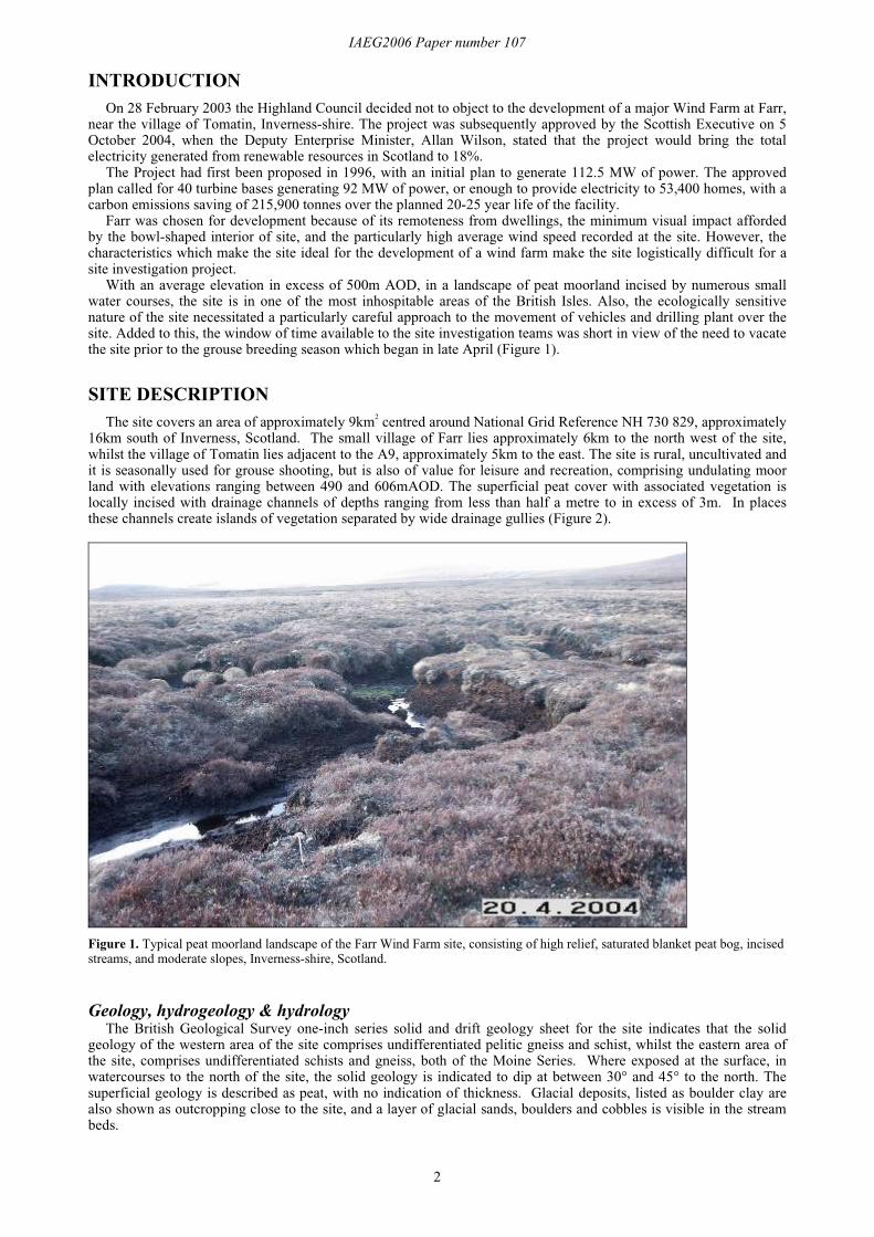
Drainage from the site is mostly towards the north with two significant gullies draining into the Uisge Dubh andultimately into the River Farnack. Drainage from the southernmost proportion of the site is towards the south,ultimately into the River Findhorn.
Figure 2. Site location map for Farr Wind Farm.
Access & logisticsIn order to advise on minimisation of disturbance to the surface ecology of the site and to record the damage caused
by the investigation, an ecologist was employed by the client who was present throughout the site activities.Access to the site at the time of the site investigation was by a 3.5km long un-surfaced track which crossed several
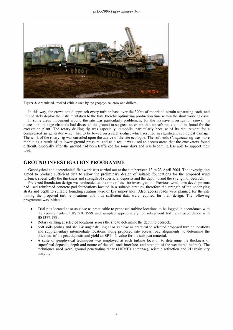
burns which could only be traversed by 4x4 vehicles. Previous ground investigations at the site proved that the bearingcapacity of the peat was limited and locally inadequate for the support of excavation plant. Low ground pressureexcavators, with wider than standard tracks, were specified to reduce the risk of further plant immobilisation. Inreality, even quad bikes could not penetrate more than a few hundred metres beyond the end of the track because ofthe numerous gullies, and thus specialist ex-military tracked vehicles were employed. These fibre-glass bodied,articulated vehicles were ideally suited to the terrain as their low weight and centre of gravity, and tracks enabledthem to negotiate all but the widest gullies with minimum impact to the peat surface. Also, the ample space allowed acrew of five to be comfortably accommodated in the front section, whilst all the instrumentation could be arranged inthe rear section. The drilling crew used a similar arrangement, with the rear cabin removed, and a rig mounted on thechassis (Figure 3).
Inverness
N
IAEG2006 Paper number 107
4
Figure 3. Articulated, tracked vehicle used by the geophysical crew and drillers.
In this way, the crews could approach every turbine base over the 300m of moorland terrain separating each, andimmediately deploy the instrumentation to the task, thereby optimizing production time within the short working days.
In some areas movement around the site was particularly problematic for the invasive investigation crews. Inplaces the drainage channels had dissected the ground to so great an extent that no safe route could be found for theexcavation plant. The rotary drilling rig was especially immobile, particularly because of its requirement for acompressed air generator which had to be towed on a steel sledge, which resulted in significant ecological damage.The work of the rotary rig was curtailed upon the advice of the site ecologist. The soft soils Competitor rig was moremobile as a result of its lower ground pressure, and as a result was used to access areas that the excavators founddifficult, especially after the ground had been trafficked for some days and was becoming less able to support theirload.
GROUND INVESTIGATION PROGRAMMEGeophysical and geotechnical fieldwork was carried out at the site between 13 to 23 April 2004. The investigation
aimed to produce sufficient data to allow the preliminary design of suitable foundations for the proposed windturbines, specifically the thickness and strength of superficial deposits and the depth to and the strength of bedrock.
Preferred foundation design was undecided at the time of the site investigation. Previous wind farm developmentshad used reinforced concrete pad foundations located in a suitable stratum, therefore the strength of the underlyingstrata and depth to suitable founding stratum were of key importance. Also, access roads were planned for the sitelinking the proposed turbine locations and thus sufficient data were required for their design. The followingprogramme was initiated:
• Trial pits located at or as close as practicable to proposed turbine locations to be logged in accordance withthe requirements of BS5930:1999 and sampled appropriately for subsequent testing in accordance withBS1377:1991
• Rotary drilling at selected locations across the site to determine the depth to bedrock.• Soft soils probes and shell & auger drilling at or as close as practical to selected proposed turbine locations
and supplementary intermediate locations along proposed site access road alignments, to determine thethickness of the peat deposits and yield an SPT - N value for the sub peat material.
• A suite of geophysical techniques was employed at each turbine location to determine the thickness ofsuperficial deposits, depth and nature of the soil-rock interface, and strength of the weathered bedrock. Thetechniques used were, ground penetrating radar (110MHz antennae), seismic refraction and 2D resistivityimaging.
IAEG2006 Paper number 107
5
Table 1: Summary of the field investigations & sampling.Investigation type Number Methods
Trial pits 30 Logged and sampled to about 5 mBGL
Rotary open boreholes 5 To a maximum of 9 mBGL
Cable percussive boreholes 25 To confirm base of peat & provided SPT N Values for sub-peat
Geophysical surveys 31 4 GPR 1 seismic refraction profile 1 resistivity profile
Natural moisture content
Organic content
pH
Sulphate & chloride
Particle size & distribution
Plasticity
Bulk & dry density
Moisture Condition Value (MCV)
Soil samples 59 bulk
samples from
29 boreholes
California Bearing Ratio (CBR)
The techniques used were targeted where possible at the exact locations of proposed wind turbines, although atsome locations the ground conditions were such that this was not feasible to access for the drilling and excavationcrews, so sites as close as practicable where substituted. However, the lighter geophysical crew was able to gainaccess to all the turbine sites available to it within the constraints of the time frame.
GEOPHYSICAL INVESTIGATIONSDetailed information on the geophysical techniques used can be found in McCann et al., (1997) and Reynolds
(1997), but a brief description of each can be found in Appendix I.The following geophysical data acquisition programme was designed to provide data at each of the 43 turbine sites
(due to time constraints caused by the impending grouse nesting season, only 31 sites were actually investigated):
• Four, 20m long GPR profiles, at 2m spacing, centred on each location, to estimate the peat thickness, and ifpossible the base of the glacial deposits.
• One, two-dimensional resistivity profile centred at each location to map combined peat and soft groundthickness, to determine the type and thickness of superficial deposits beneath the peat, and to indicate thedepth to rock head and bedrock type.
• One, seismic refraction profile centred at each turbine location to estimate overburden thickness andstiffness, depth to and competence of the bedrock.
The acquisition parameters for the seismic refraction and 2D Resistivity profiles were decided at each specific sitein order to optimise resolution and depth of investigation. These parameters were decided from the GPR results whichgave an accurate in-field determination of the peat layer thickness. The locations of all the geophysical survey profileswhere located by GPS to an accuracy of +0.5 m.
Geophysical data acquisition & interpretationThe geophysical data underwent some initial processing in the field in order to ensure data quality and to enable
adjustment of the recording parameters to optimise resolution at each site.The data were then transmitted to the office by a mobile telephone link for additional processing and initial
interpretation. This enabled feed-back from the processing centre to be used to further modify acquisition parameters.Final processing and interpretation was carried out incorporating the results from the geotechnical investigation (trialpits and borehole records).
The results of the geophysical surveys indicated a horizontally stratified sequence, and confirmed the presence of ahighly variable thickness of peat, above dense glacial till which was deposited on fractured and weathered bedrock.
Ground Penetrating RadarFigure 4 shows examples of four GPR profiles from different turbine bases with varying peat thicknesses across the
site.
IAEG2006 Paper number 107
6
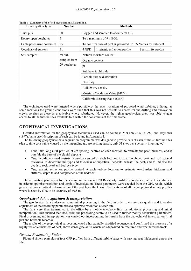
Figure 4. Examples of Ground Penetrating Radar profiles from four different turbine bases, note the different peat thicknesses andtopography of the base of peat horizon.
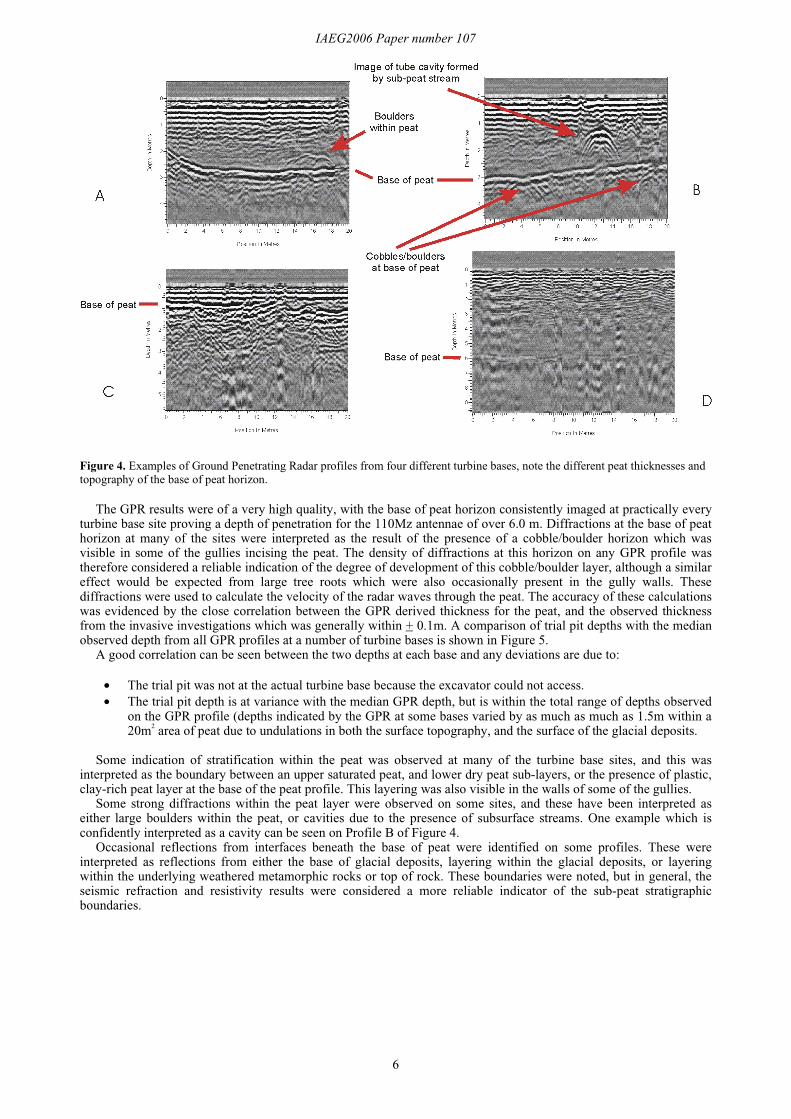
The GPR results were of a very high quality, with the base of peat horizon consistently imaged at practically everyturbine base site proving a depth of penetration for the 110Mz antennae of over 6.0 m. Diffractions at the base of peathorizon at many of the sites were interpreted as the result of the presence of a cobble/boulder horizon which wasvisible in some of the gullies incising the peat. The density of diffractions at this horizon on any GPR profile wastherefore considered a reliable indication of the degree of development of this cobble/boulder layer, although a similareffect would be expected from large tree roots which were also occasionally present in the gully walls. Thesediffractions were used to calculate the velocity of the radar waves through the peat. The accuracy of these calculationswas evidenced by the close correlation between the GPR derived thickness for the peat, and the observed thicknessfrom the invasive investigations which was generally within + 0.1m. A comparison of trial pit depths with the medianobserved depth from all GPR profiles at a number of turbine bases is shown in Figure 5.
A good correlation can be seen between the two depths at each base and any deviations are due to:
• The trial pit was not at the actual turbine base because the excavator could not access.• The trial pit depth is at variance with the median GPR depth, but is within the total range of depths observed
on the GPR profile (depths indicated by the GPR at some bases varied by as much as much as 1.5m within a20m2 area of peat due to undulations in both the surface topography, and the surface of the glacial deposits.
Some indication of stratification within the peat was observed at many of the turbine base sites, and this wasinterpreted as the boundary between an upper saturated peat, and lower dry peat sub-layers, or the presence of plastic,clay-rich peat layer at the base of the peat profile. This layering was also visible in the walls of some of the gullies.
Some strong diffractions within the peat layer were observed on some sites, and these have been interpreted aseither large boulders within the peat, or cavities due to the presence of subsurface streams. One example which isconfidently interpreted as a cavity can be seen on Profile B of Figure 4.
Occasional reflections from interfaces beneath the base of peat were identified on some profiles. These wereinterpreted as reflections from either the base of glacial deposits, layering within the glacial deposits, or layeringwithin the underlying weathered metamorphic rocks or top of rock. These boundaries were noted, but in general, theseismic refraction and resistivity results were considered a more reliable indicator of the sub-peat stratigraphicboundaries.
IAEG2006 Paper number 107
7
Figure 5. Comparison of peat thickness derived from GPR and trial pits at several turbine sites.
2D resistivity imagingThe resistivity profiles for each base were interpreted with reference to the corresponding GPR and seismic
refraction results. The GPR and seismic results provided the depth control which enabled the correct resistivitycontour to be assigned to the appropriate geoelectrical/stratigraphical boundary. The resistivity results wereparticularly useful for characterising the peat layer, and, in conjunction with the seismic refraction results, identifyingthe boundary between the upper and lower peat units.
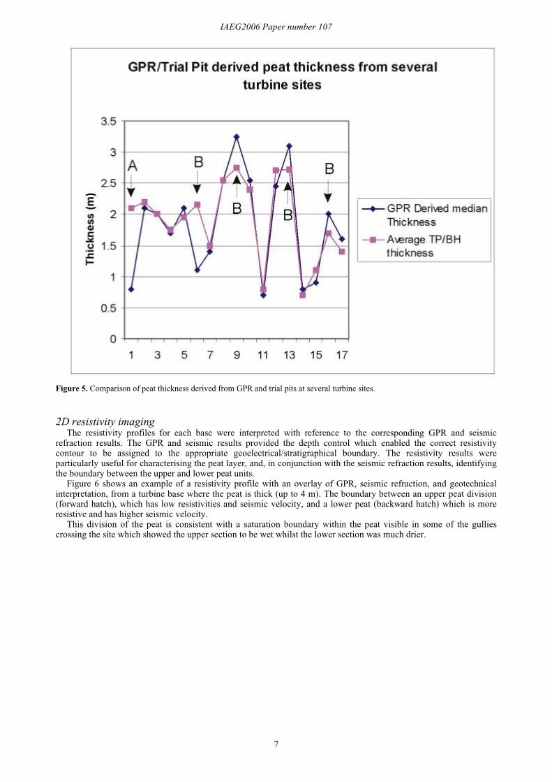
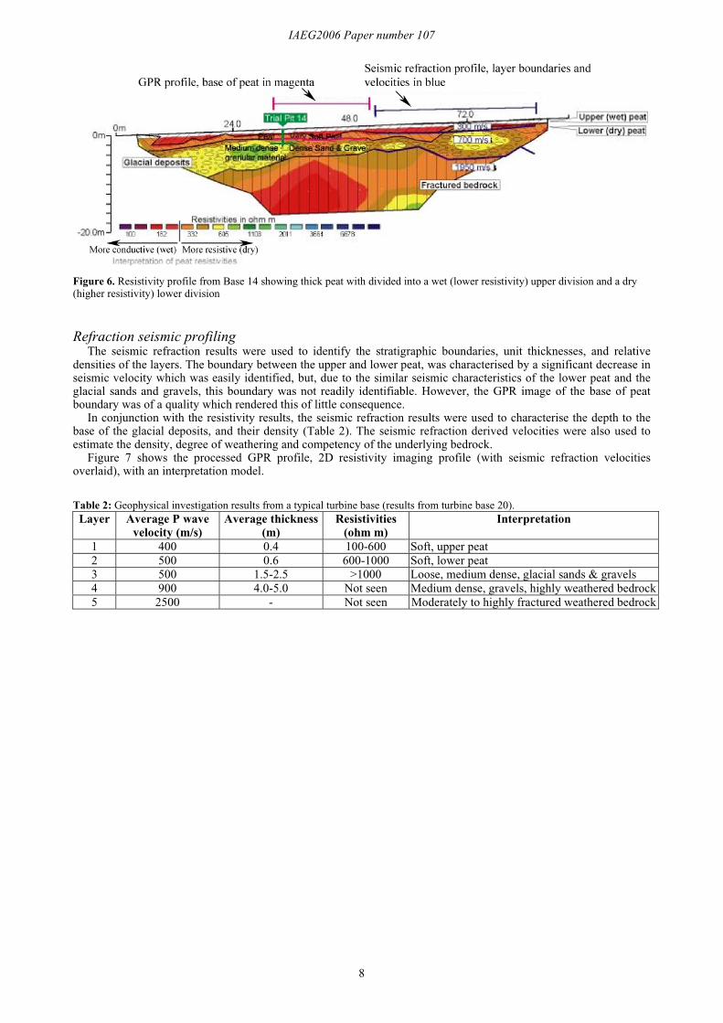
Figure 6 shows an example of a resistivity profile with an overlay of GPR, seismic refraction, and geotechnicalinterpretation, from a turbine base where the peat is thick (up to 4 m). The boundary between an upper peat division(forward hatch), which has low resistivities and seismic velocity, and a lower peat (backward hatch) which is moreresistive and has higher seismic velocity.
This division of the peat is consistent with a saturation boundary within the peat visible in some of the gulliescrossing the site which showed the upper section to be wet whilst the lower section was much drier.
IAEG2006 Paper number 107
8
Figure 6. Resistivity profile from Base 14 showing thick peat with divided into a wet (lower resistivity) upper division and a dry(higher resistivity) lower division
Refraction seismic profilingThe seismic refraction results were used to identify the stratigraphic boundaries, unit thicknesses, and relative
densities of the layers. The boundary between the upper and lower peat, was characterised by a significant decrease inseismic velocity which was easily identified, but, due to the similar seismic characteristics of the lower peat and theglacial sands and gravels, this boundary was not readily identifiable. However, the GPR image of the base of peatboundary was of a quality which rendered this of little consequence.
In conjunction with the resistivity results, the seismic refraction results were used to characterise the depth to thebase of the glacial deposits, and their density (Table 2). The seismic refraction derived velocities were also used toestimate the density, degree of weathering and competency of the underlying bedrock.
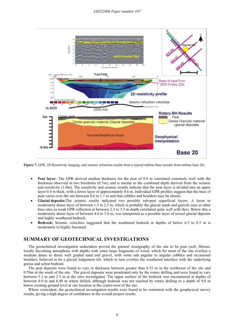
Figure 7 shows the processed GPR profile, 2D resistivity imaging profile (with seismic refraction velocitiesoverlaid), with an interpretation model.
Table 2: Geophysical investigation results from a typical turbine base (results from turbine base 20).Layer Average P wave
velocity (m/s)Average thickness
(m)Resistivities
(ohm m)Interpretation
1 400 0.4 100-600 Soft, upper peat2 500 0.6 600-1000 Soft, lower peat3 500 1.5-2.5 >1000 Loose, medium dense, glacial sands & gravels4 900 4.0-5.0 Not seen Medium dense, gravels, highly weathered bedrock5 2500 - Not seen Moderately to highly fractured weathered bedrock
IAEG2006 Paper number 107
9
Figure 7. GPR, 2D Resistivity imaging, and seismic refraction results from a typical turbine base (results from turbine base 20).
• Peat layer: The GPR derived median thickness for the peat of 0.8 m correlated extremely well with thethickness observed in two boreholes (0.7m), and is similar to the combined depth derived from the seismicand resistivity (1.0m). The resistivity and seismic results indicate that the peat layer is divided into an upperlayer 0.4 m thick; with a lower layer of approximately 0.6 m. Individual GPR profiles suggest that the base ofpeat varies over the site between 0.6 to 1.1 m and that cobbles and boulders may be absent.
• Glacial deposits:The seismic results indicated two possible sub-peat superficial layers. A loose tomoderately dense layer of between 1.5 to 2.5 m, which is probably the glacial sands and gravels seen at otherbase sites (a weak GPR reflection at between 2.5 to 3.5 m depth correlated quite well with this). Below this amoderately dense layer of between 4.0 to 5.0 m, was interpreted as a possible layer of mixed glacial depositsand highly weathered bedrock.
• Bedrock: Seismic velocities suggested that the weathered bedrock at depths of below 6.5 to 8.5 m ismoderately to highly fractured.
SUMMARY OF GEOTECHNICAL INVESTIGATIONSThe geotechnical investigation undertaken proved the general stratigraphy of the site to be peat (soft, fibrous,
locally becoming amorphous with depth) with some large fragments of wood, which for most of the site overlies amedium dense to dense well graded sand and gravel, with some sub angular to angular cobbles and occasionalboulders, believed to be a glacial lodgement till; which in turn overlies the weathered interface with the underlyinggneiss and schist bedrock
The peat deposits were found to vary in thickness between greater than 6.55 m in the northwest of the site and0.70m in the south of the site. The gravel deposits were penetrated only by the rotary drilling and were found to varybetween 5.3 m and 2.3 m at the sites investigated. The upper surface of the bedrock was encountered at depths ofbetween 4.0 m and 6.40 m where drilled, although bedrock was not reached by rotary drilling to a depth of 9.0 mbelow existing ground level at one location in the centre-west of the site.
Where coincident, the geotechnical investigation results were found to be consistent with the geophysical surveyresults, giving a high degree of confidence in the overall project results.
IAEG2006 Paper number 107
10
CONCLUSIONSA summary of the main achievements of the ground investigation areas follows:
• Geotechnical data was acquired at a series of specific sites each separated by hundreds of metres of difficultterrain. This data was of a consistent high quality.
• The time-constraints incumbent on the data acquisition phase, coupled with the difficult terrain, and the needto avoid damage to the environment required a light and highly mobile acquisition team.
• The geophysical data both augmented the drilling and trial pitting data, and provided additional data fromsites which were inaccessible to the heavier plant. The geophysical techniques enabled the point-dataprovided by the drilling and trial-pitting to be extended to the whole of the footprint area of the turbine bases.
• The results of the geophysical investigation were consistent with the geotechnical investigation, but alsohighlighted some pitfalls in a purely invasive investigation strategy where only point data is acquired. Inparticular, the large variations in peat thickness over distances of a few metres would not have been apparentfrom a limited number of trial pits or boreholes. Thus the geophysics is able to accurately extend theknowledge of the subsurface away from the single point at which trial pit has been sited.
The ground investigation shows the efficacy of a combined investigation involving both invasive and non-invasivemethodologies to extract the optimum geotechnical data for the design of a major infrastructure development with theminimum environmental impact in a very short time-frame. This was particularly important in the case of the FarrWind Farm in view of the sensitivity of the landscape in which it is sited.
As urban areas grow and expand in size and demand increasingly more resources, pressure on the surrounding rurallandscapes to provide these resources will inevitably rise. In the face of a parallel move towards sensible andsustainable exploitation of these resources, equal pressure will be exerted to ensure that the integrity and naturalbeauty of these areas is not unduly affected. The Farr Wind Farm investigation proves that this is possible.
Acknowledgements: The authors would like acknowledge Apex Geoservices Ltd, Halcrow Group Limited and Jeroen Pieterse forassistance with translation.
Corresponding author: Dr Laurance Donnelly, Halcrow, Deanway Technology Centre, Wilmslow Road, Handforth, Cheshire,SK9 3FB, United Kingdom. Tel: +44 (0) 1625 540 456. Email: [email protected]
REFERENCESBRITISH GEOLOGICAL SURVEY 1914 & 1964. One-Inch Series, Scotland Sheet 74 – Grantown on Spey, Solid and Drift
Edition. The Ordnance Survey.BRITISH STANDARDS 5930, 1999. Code of Practise for Site Investigations.BRITISH STANDARDS 1377, 1991. Method of tests for soils for civil engineering purposes.McCANN D. M., EDDLESTONE, M., FENNING P. J., REEVES, G. M., 1997; Geological Society Engineering Geology Special
Publication No 12, Modern Geophysics in Engineering Geology, The Geological Society of London.ORDNANCE SURVEY, 2002. 1:25 000 Explorer Sheet 417. Monadhliath Mountains North & Strathdearn. Edition A. The
Ordnance Survey.ORDNANCE SURVEY, 1:50 000, Landranger Sheet 35. Kingussie & Monadhliath Mountains. The Ordnance Survey.REYNOLDS, J. M., 1997. An Introduction to Applied and Environmental Geophysics, John Wiley & Sons, Chicester
APPENDIX I: DESCRIPTION OF GEOPHYSICAL TECHNIQUESGround Penetrating Radar (GPR): This method uses a radar antenna transmitting electromagnetic energy in
pulse form. Measurements are taken for the time taken for the artificially induced radar pulse to be reflected from astratigraphic interface. Partial reflections occur at interfaces with different geoelectical properties (within the solid andsuperficial geology), back to a receiving antenna; this provides information on the depth to bedrock (i.e. thicknesses ofpeat and superficial deposits). In general, clay-rich and water saturated soils have a lower penetration than gravel anddry soils. However, signal penetration and resolution limits are also influenced by the frequency of the transmittedelectromagnetic pulse. High frequencies give better resolution but shallow penetration. Lower frequencies give lowerresolution and deeper penetration.
Electrical resistivity: This method measures small changes in the electrical resistance of the ground between anelectrode array; this provides an indication of the depth to the base of the peat. The two-dimensional Wennerresistivity array was used, whereby four electrodes are selected from an array of 32 placed in a line in the ground anda current is passed through the two outer electrodes, and the potential difference is measured across the two innerelectrodes. The survey continues using a sequence of electrode configurations from the array until all possibleconfigurations have been used. The resulting series of values from along the profile are then processed using industrystandard software to produce a resistivity profile of the ground under investigation.

IAEG2006 Paper number 107
11
Seismic refraction: This method measures the velocity of refracted seismic waves through the superficial depositsand bedrock. A sonic pulse is generated by striking the ground with a sledge hammer, and the resulting seismic wavesare detected by an array of geophones connected via a multi-core cable to a seismograph. By processing the resultingdata, a profile of the ground under investigation can be constructed giving the depth and characteristics of thesuperficial deposits/bedrock interface. Stiffer and stronger materials usually have higher seismic velocities, while soft,loose or fractured deposits have lower velocities.