Embed Size (px)
Citation preview
The FAO-Thiaroye Processing Technique (FTT)
Guidance for building and using the FTT for
smoking fish
Based on experience from adapting it to the
context of the Federated States of Micronesia

The FAO-Thiaroye Processing Technique (FTT)
Prepared by
Joseph Nyemah Nyemah Bandara Rotawewa
FOOD AND AGRICULTURE ORGANIZATION OF THE UNITED NATIONS Apia, 2021

Required citation: Nyemah Nyemah, J. and Rotawewa, B. 2021. The FAO-Thiaroye Processing Technique (FTT). Apia. https://doi.org/10.4060/cb3299en
The designations employed and the presentation of material in this information product do not imply the expression of any opinion whatsoever on the part of the Food and Agriculture Organization of the United Nations (FAO) concerning the legal or development status of any country, territory, city or area or of its authorities, or concerning the delimitation of its frontiers or boundaries. The mention of specific companies or products of manufacturers, whether or not these have been patented, does not imply that these have been endorsed or recommended by FAO in preference to others of a similar nature that are not mentioned. The views expressed in this information product are those of the author(s) and do not necessarily reflect the views or policies of FAO. ISBN 978-92-5-133960-2 © FAO, 2021
Some rights reserved. This work is made available under the Creative Commons Attribution-NonCommercial-ShareAlike 3.0 IGO licence (CC BY-NC-SA 3.0 IGO; https://creativecommons.org/licenses/by-nc-sa/3.0/igo/legalcode). Under the terms of this licence, this work may be copied, redistributed and adapted for non-commercial purposes, provided that the work is appropriately cited. In any use of this work, there should be no suggestion that FAO endorses any specific organization, products or services. The use of the FAO logo is not permitted. If the work is adapted, then it must be licensed under the same or equivalent Creative Commons licence. If a translation of this work is created, it must include the following disclaimer along with the required citation: “This translation was not created by the Food and Agriculture Organization of the United Nations (FAO). FAO is not responsible for the content or accuracy of this translation. The original [Language] edition shall be the authoritative edition.” Disputes arising under the licence that cannot be settled amicably will be resolved by mediation and arbitration as described in Article 8 of the licence except as otherwise provided herein. The applicable mediation rules will be the mediation rules of the World Intellectual Property Organization http://www.wipo.int/amc/en/mediation/rules and any arbitration will be conducted in accordance with the Arbitration Rules of the United Nations Commission on International Trade Law (UNCITRAL). Third-party materials. Users wishing to reuse material from this work that is attributed to a third party, such as tables, figures or images, are responsible for determining whether permission is needed for that reuse and for obtaining permission from the copyright holder. The risk of claims resulting from infringement of any third-party-owned component in the work rests solely with the user. Sales, rights and licensing. FAO information products are available on the FAO website (www.fao.org/publications) and can be purchased through [email protected]. Requests for commercial use should be submitted via: www.fao.org/contact-us/licence-request. Queries regarding rights and licensing should be submitted to: [email protected]. All photos and graphics ©FAO/ B.Rotawewa
iii
CONTENTS ACKNOWLEDGEMENTS ............................................................................................................. iv
INTRODUCTION .......................................................................................................................... 1
CHARACTERISTICS OF THE FSM ADAPTED FTT .......................................................................... 3
CONSTRUCTION OF THE FTT KILN .............................................................................................. 5
FABRICATION OF METAL PARTS .............................................................................................. 16
Material selection ................................................................................................................ 18
Smoker lid ............................................................................................................................ 24
Smoking Rack ....................................................................................................................... 28
Fat collection tray ................................................................................................................ 31
Furnace ................................................................................................................................ 39
PREPARATION AND SMOKING PROCESS ................................................................................. 51
Packing and storing .............................................................................................................. 59
MAINTENANCE OF THE FTT AND IT'S ACCESSORIES ................................................................ 61
THE SHELTER ............................................................................................................................ 64
SUMMARY OF ESTIMATES ....................................................................................................... 67
REFERENCES ............................................................................................................................. 70
TABLES Table 1: Material List for a two-compartment FTT kiln ............................................................. 5
Table 2: Labor requirement (For a two-compartment kiln) ...................................................... 6
Table 3: Summary of the cost of the materials required to fabricate metal parts according to FSM market prices. .......................................................................................................... 16
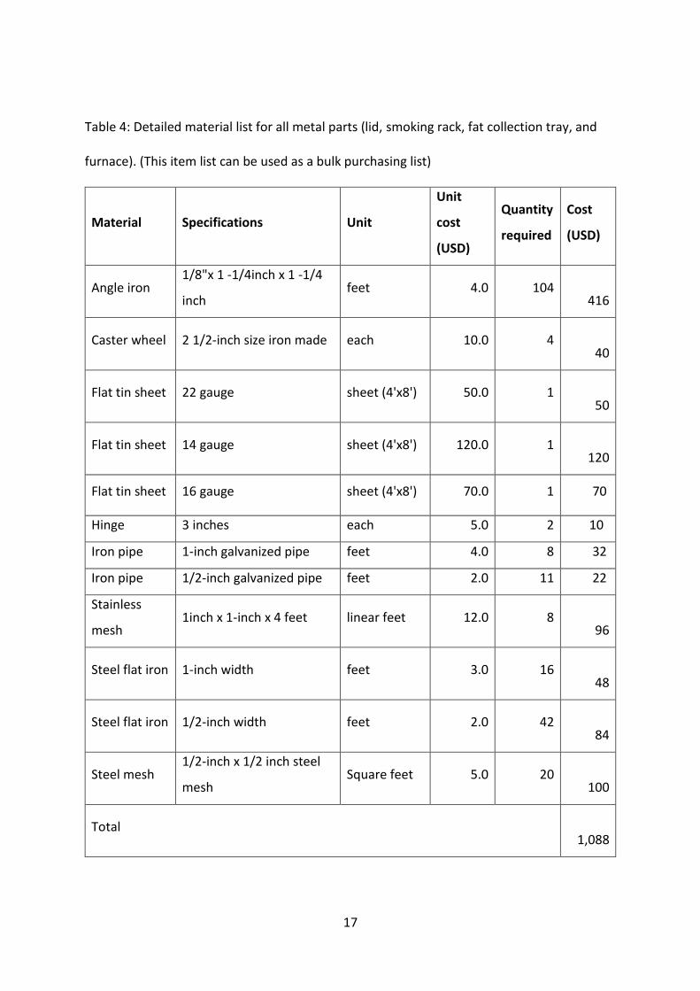
Table 4: Detailed material list for all metal parts (lid, smoking rack, fat collection tray, and furnace). (This item list can be used as a bulk purchasing list) ....................................... 17
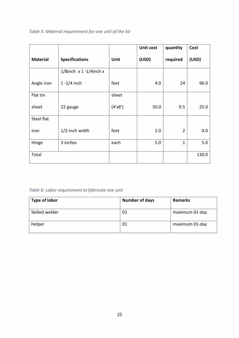
Table 5: Material requirement for one unit of the lid ............................................................. 25
Table 6: Labor requirement to fabricate one unit ................................................................... 25
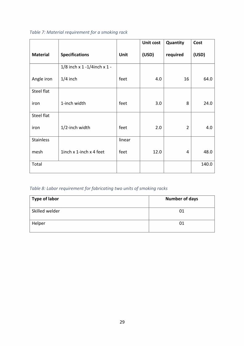
Table 7: Material requirement for a smoking rack .................................................................. 29
Table 8: Labor requirement for fabricating two units of smoking racks ................................. 29
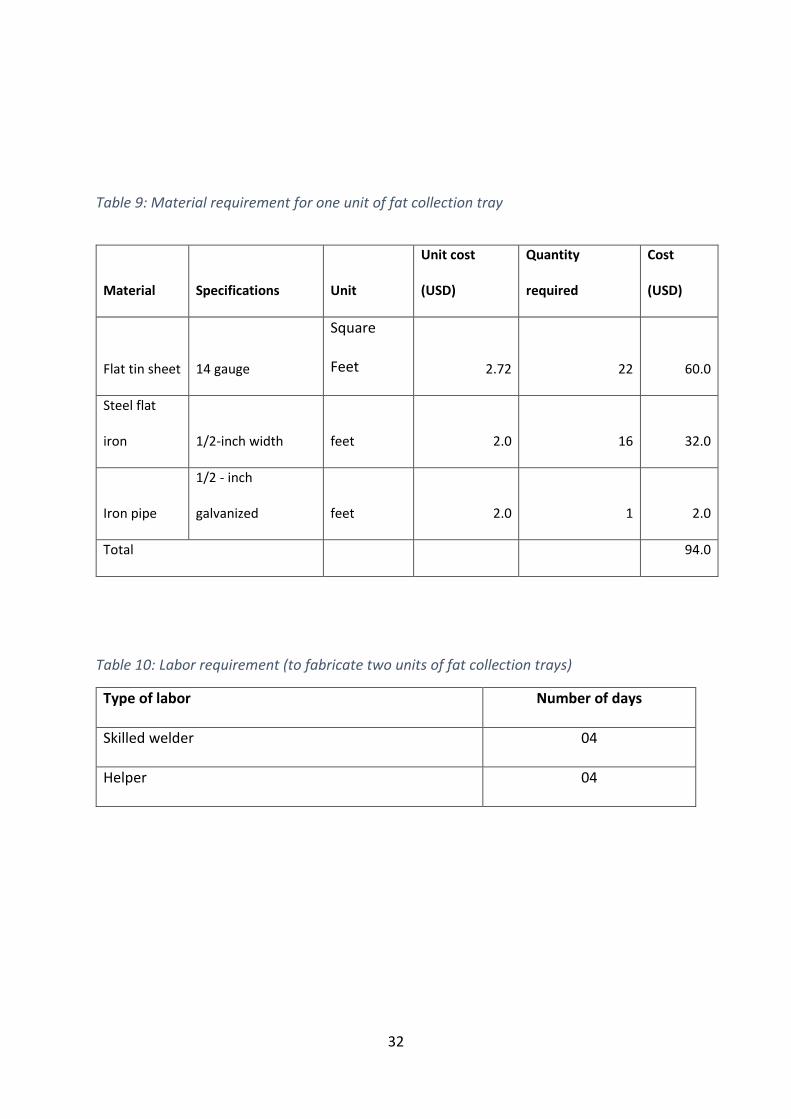
Table 9: Material requirement for one unit of fat collection tray ........................................... 32
Table 10: Labor requirement (to fabricate two units of fat collection trays) .......................... 32
Table 11: Material requirement for furnace............................................................................ 40
Table 12: Labor requirement for one unit of furnace ............................................................. 40
Table 13: Materials for the shed .............................................................................................. 64
Table 14: Summary of the cost of the project ......................................................................... 67
Table 15: Detailed Estimated Cost for Construction of Metal Parts, FTT Kiln and Shelter ..... 67 FIGURES Figure 1: The 3D image of FTT kiln (front view) ......................................................................... 6
Figure 2: The 3D image of FTT kiln (side top view) .................................................................... 7 Figure 3: Cement hollow blocks. ................................................................................................ 7
Figure 4: Cement hollow blocks ................................................................................................. 8
Figure 5: The width of the hollow cement block is important. ................................................. 8

iv
Figure 6: Layout the cement blocks on the 3-inch concrete floor of the shelter ...................... 9
Figure 7: Two layers of blocks .................................................................................................... 9
Figure 8: Formwork for placing a concrete beam .................................................................... 10
Figure 9: Concrete beam was placed ....................................................................................... 10
Figure 10: Check measurements that correctly fit the fat collection tray/smoking rack ........ 11
Figure 11: Continuous vigilance on inner measurements ....................................................... 11
Figure 12: Fix the rebars and iron tubs pieces at the correct beam ........................................ 12
Figure 13: Fix the rebars and iron tubs pieces at the correct height....................................... 12
Figure 1: The 3D image of FTT inside of the kiln ...................................................................... 13
Figure 15: Brick works completed ........................................................................................... 13 Figure 16: Outside plastering is recommended ....................................................................... 14
Figure 17: The walls of the kiln and metal parts fix well ......................................................... 14
Figure 18: FTT kiln side view .................................................................................................... 15
Figure 19: FTT kiln ready to use ............................................................................................... 15
Figure 20: Angled iron .............................................................................................................. 18
Figure 21: Tin sheets ............................................................................................................... 19
Figure 22: Caster wheel ........................................................................................................... 20
Figure 23: Iron tubes ................................................................................................................ 20 Figure 24: Iron tubes ................................................................................................................ 21
Figure 25: Stainless wire mesh ................................................................................................ 21
Figure 26: Flat iron ................................................................................................................... 22
Figure 27: 1/2 inch flat iron ..................................................................................................... 23
Figure 28: Galvanized steel mesh ............................................................................................ 24
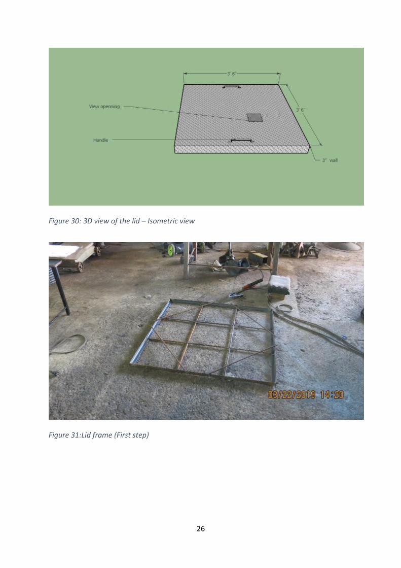
Figure 29: 3D view of the lid – Isometric view ........................................................................ 26
Figure 30: Lid frame (First step ................................................................................................ 26
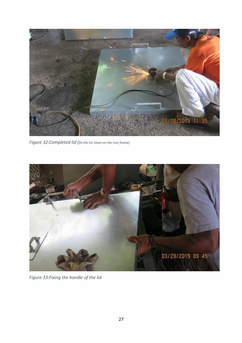
Figure 31: Completed lid (fix the tin sheet on the iron frame) ................................................ 27 Figure 32: Fixing the handle of the lid ..................................................................................... 27
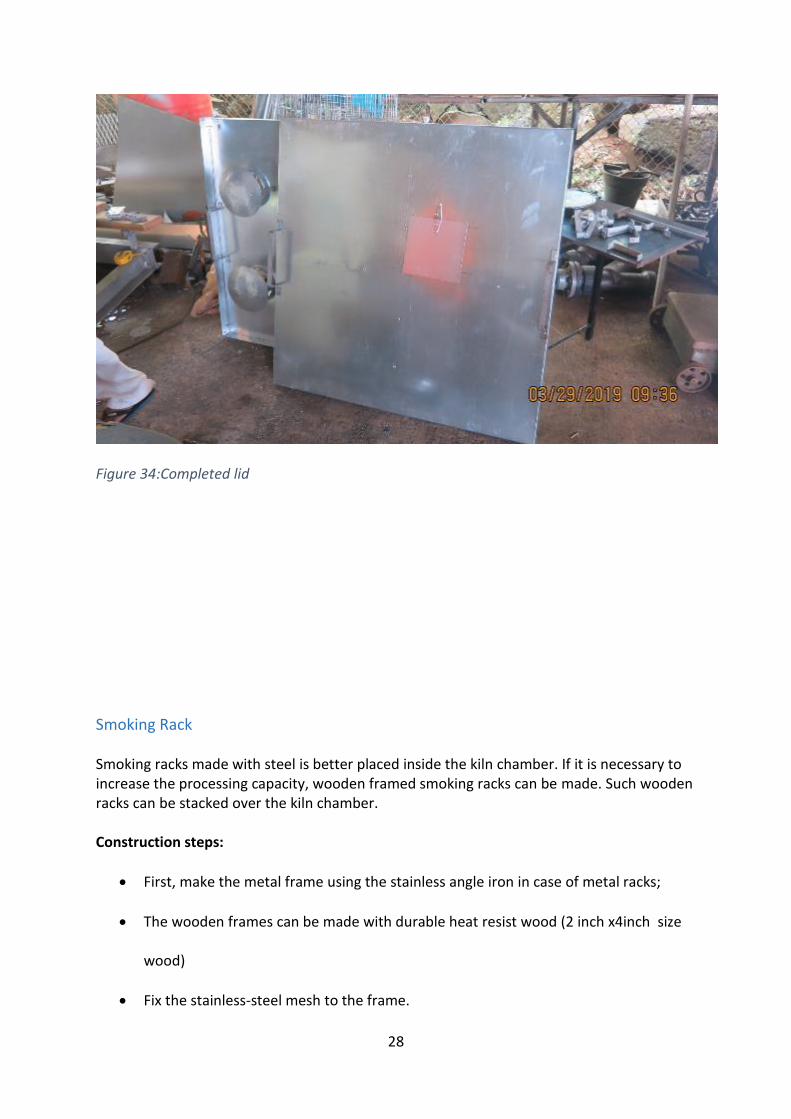
Figure 33: Completed lid .......................................................................................................... 28
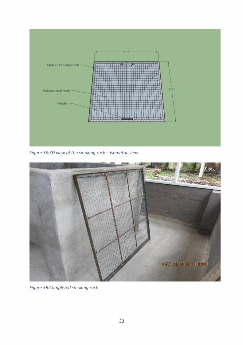
Figure 34: 3D view of the smoking rack – Isometric view ....................................................... 30
Figure 35: Completed smoking rack ........................................................................................ 30
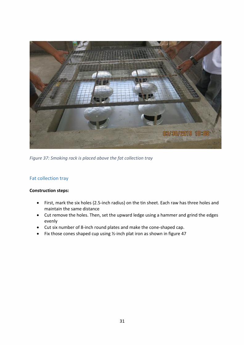
Figure 36: Smoking rack is placed above the fat collection tray ............................................. 31
Figure 37: 3D view of the fat collection tray – Isometric view ............................................... 33
Figure 38: 3D view of the fat collection tray – Isometric view ................................................ 33
Figure 39: 3D view of the fat collection tray – bottom view ................................................... 34 Figure 40: Welder marks the holes with a pencil .................................................................... 34
Figure 41: Cutting six holes ...................................................................................................... 35
Figure 42: Cut removed six holes ............................................................................................. 35
Figure 43: Making the ledge with a hammer ........................................................................... 36
Figure 44: The edges are evenly grinded ................................................................................. 36
Figure 45: Round steel plates for coned shaped cap .............................................................. 37
Figure 46: Welding the edges .................................................................................................. 37
Figure 47: Fat collection tray mounted inside the kiln during construction ........................... 38 Figure 48: View of fat collection tray inside the kiln ............................................................... 38
Figure 49: 3D view of the metal box for a furnace. ................................................................. 41
Figure 50: 3D view of the ash pan ........................................................................................... 41
Figure 51: 3D view after ash pan and air tube (side view) ...................................................... 42
Figure 52: 3D view after ash pan and air tube (front view) ..................................................... 42
v
Figure 53: 3D view after ash pan and air tube with handle (front view) ................................ 43
Figure 54: 3D view of the ember/charcoal mesh (front view) ................................................ 43
Figure 55: 3D view of the furnace (front view). ....................................................................... 44 Figure 56: 3D view of the furnace (side view) ......................................................................... 44
Figure 57: 3D view of the furnace (bottom view) .................................................................... 45
Figure 58: Metal box ................................................................................................................ 45
Figure 59: Fixing the caster wheels and ashtray holder .......................................................... 46
Figure 60: The caster wheels and ashtray holder .................................................................... 46
Figure 61: Opening for an ashtray .......................................................................................... 47
Figure 62: Hole for air tubes .................................................................................................... 47
Figure 63: Fixing the air tubes .................................................................................................. 48 Figure 64: Fixing the air tubes .................................................................................................. 49
Figure 65: Fixing the air tubes and handle............................................................................... 49
Figure 66: Ember/ charcoal tray .............................................................................................. 50
Figure 67: Furnace ready to insert into the kiln ...................................................................... 51
Figure 68: Flow diagram of the smoking process using FTT .................................................... 52
Figure 69: Tuna fillets 1 ½ inch thickness ............................................................................... 53
Figure 70: A reef fish ................................................................................................................ 53
Figure 71: The reef fish after scaling and gut cleaning ............................................................ 54 Figure 72: Tuna fillet seasoning (soy sauce, sugar and pepper) .............................................. 55
Figure 73: Tuna fillet seasoning (sugar and salt) ..................................................................... 55
Figure 74: Tuna fillet smoking .................................................................................................. 56
Figure 75: Smaller fish can be hanged by steel hooks ............................................................. 57
Figure 76: After three hours of smoking .................................................................................. 57
Figure 77: Smoked tuna fillet ................................................................................................. 58
Figure 78: Coconut husk ......................................................................................................... 59
Figure 79: Hard fuelwood ........................................................................................................ 59 Figure 80: Vaccum packing - reef fish ...................................................................................... 59
Figure 81: Vaccum packing ...................................................................................................... 60
Figure 82: Tuna fillet vacuum packing ..................................................................................... 60
Figure 83: Zip Lock Bags packing .............................................................................................. 61

iv
ACKNOWLEDGEMENTS This manual is a result of the FAO TCP/MIC/3604 “Piloting Sustainable Fish Value Chain with extended shelf-life products” implemented by the FAO Regional Office for Asia and the Pacific upon request from the Government of the Federated States of Micronesia (FSM). The FSM Department of Resources and Development, FSM Department of Health, Pohnpei State Resources and Development, and Social Affairs were the implementing partners. The authors express their gratitude to the FSM government and implementing partners for their great spirit of cooperation and active contribution to the project. The authors extend their special thanks to FAO consultants Beyons Yalaine, Ann Hayman, Saimon Mix and the FSM National Project Coordinator, Valentin Martin for their invaluable contributions to the project. The inputs and cooperation from local communities and the Island Food Community of Pohnpei (NGO) are highly appreciated. The authors express their heartfelt gratitude to the nmany experts and community practitioners in FSM and Samoa, who reviewed the manual and provided feedback for improvement. Kevin Hadfield provided expertise in graphic editing. Jennifer D John graces page seven (vii). Members of FAO Regional Office for Asia and the Pacific were always behind the project from its formulation to successful completion. May they find here the expression of our gratitude.
v
1
INTRODUCTION The Food and Agriculture Organization of the United Nations (FAO) is a specialized agency that
leads international efforts to defeat hunger. As part of its various initiatives aimed at improving
food security and nutrition, FAO is always researching and developing new, improved and locally
adaptable tools for extending the shelf life of, and adding value to scarce and surplus natural
resources to improve local access and availability. The FAO-Thiaroye Processing Technique (FTT)
was developed by a partnership between FAO and the National Training Centre for Fisheries and
Aquaculture Technicians (CNFTPA) in Senegal to address identified shortcomings of existing
African fish processing kilns (FAO, 2019). The smoking technique, popularly used in many African
countries for producing smoked fish, was successfully introduced to fish processers in Sri Lanka
and the Federated States of Micronesia (FSM) in 2016 and 2018, respectively.
The introduction of the FTT across different social, cultural, environmental and economic
contexts comes with the need for adaptation. The construction, operation and maintenance of
the original model are documented in several publications (see FAO, 2019; Mindjimba et al.,
2019). This manual contributes to these efforts by capturing the adaptation experience of the
original FTT in the local FSM context. The modification and adaptation of the FTT in FSM were
driven by the following key factors:
From metric systems to imperial systems: In the countries where the FTT was previously built
and operated, measurements are based on the metric systems, as opposed to the imperial
systems used in FSM. This difference has implications for constructing the kiln.
From using the FTT only for fish smoking to using it as a multi-food processing device: The
original purpose that informed the conceptualization of the FTT in Senegal is fish smoking.
However, after looking at pictures of the device, the population of FSM decided that they could
2
also use it to smoke pork, grill breadfruit, taro, yams and other local foods. All of the results were
promising, but need to be further validated. For example, we discovered that more time is
needed to adjust the heat for smoking pork. This would also determine precisely what the result
would be for either further processing or direct consumption from the oven. The potential for
these multi-purpose applications has implications for constructing the FTT; for example, the
spacing of the rack base was reconsidered. All of these possibilities will also come with the need
for food safety considerations, it is important to ensure that the oven is thoroughly cleaned prior
to using with a different food product to avoid contamination and potential food hazards..
From producing strong to mild smoke flavored products: The FSM local community is used to
“Sashimi" and "Sushi" type Japanese style flavor and mouthfeel. Therefore, a shorter smoking
duration, seasoning and cutting techniques were introduced. To address this need, the FTT was
adapted with the possibility of controlling the intensity of its fuel supply.
3
CHARACTERISTICS OF THE FSM ADAPTED FTT The FTT designed for the FSM context has the following components as the original version but
with slight mechanical adaptations. The major revision to the FTT prototype is removing the
external smoke generator system. This change resulted in cheaper construction costs, increased
processing capacity and shorter processing time while maintaining an appealing product color
and flavor.
Kiln: This is the housing component for the kiln. The openings at the bottom are for the furnace.
The fat collection trays are positioned in the middle of the kiln chambers, while the smoking racks
are positioned in the upper part of the kiln. In FSM, only hollow cement blocks are available for
construction works. A thicker wall is always better; therefore, the cement blocks with a five and
a half-inch or more were used for the Kiln construction. The hollows were filled with small
stones and a sand-cement mixture for strength and heat protection.
Smoking racks: The smoking racks are movable and used to lay out fish for smoking. The racks
can be made with steel frame and galvanized mesh or wooden frame with galvanized mesh. Steel
frame racks are suitable to place inside the kiln, while wooden frame racks can be placed on the
kiln top to increase the processing capacity.
Fat collection trays: This is a special device made of a metal sheet for collecting fat while cooking
the fish. The holes pass through the heat from the furnace while the cone-shaped cap prevents
4
fat and exudate from falling on to the fire. The device is positioned slightly tilted, allowing the oil
can drip towards the edge and pass out through the holes.
Lids: They are used to cover the products from the top opening of the kiln during smoking.
Generally made up of thin tin sheets that are easy to move.
Furnace: This component is made with metal to hold the fuelwood/charcoal and supply heat for
smoking. The furnace can be moved in and out of the kiln.
Note: A careful market survey was completed to select suitable and affordable materials for
smoking racks, lids, and the furnace. This is crucial because the availability of iron material greatly
differs based on the location.
Shed: From the food safety perspective, it is essential to place the FTT under a properly built
shelter.
Comparative Advantage: The foreging adaptation and characteristics of the FTT make a
compelling case for highlighting its comparative advantage. It is however important to declare
upfront that the need to conduct further tests for the multipurpose capacity combined with the
fact that the FTT remains subject to improvements presents the articulation of its comparative
advantage wihout imperfections.
At this evolving stage of the FTT, a key comparative advantage is its adaptability in terms of size
and the heat, which is proven from when it was created in Senegal. It seems that it will evolve
significantly over time and in different social, cultural and economic contexts. Another key
comparative advantage is the fact that the FTT can be powered purely by heat generated by a
somewhat environmentally and economically friendly materials, for example coconut husks that
don’t need to be purchansed, but that are also easily decompostable. Lastly, the FTT is
technologically basic, for example, you don’t need to a two day workshop in order to train people
over how to use it.
5
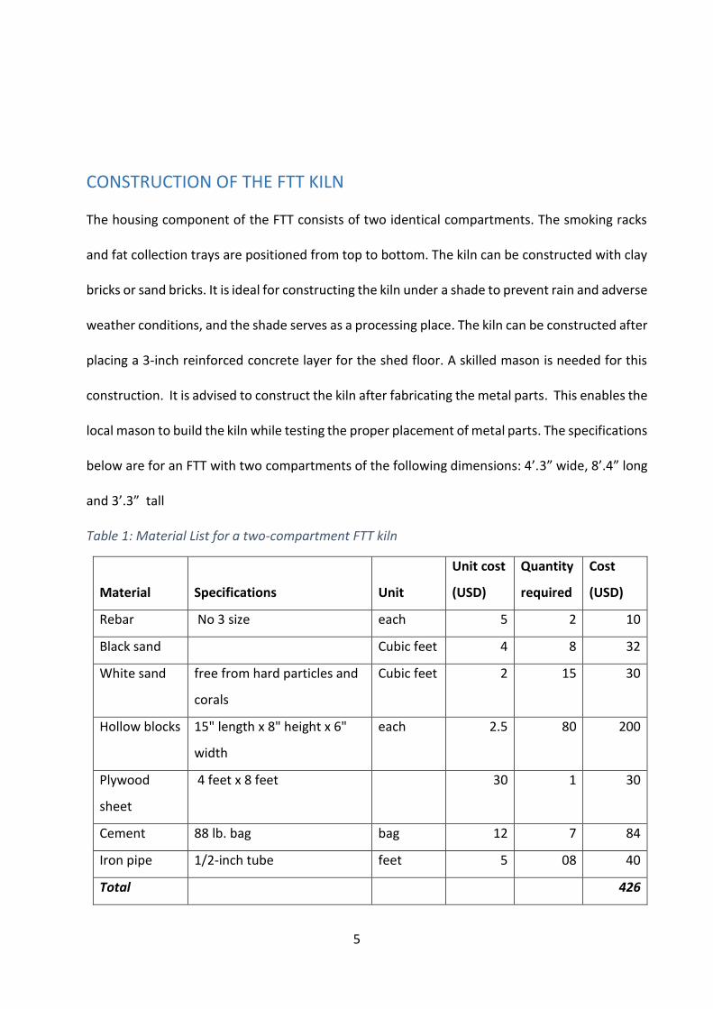
CONSTRUCTION OF THE FTT KILN The housing component of the FTT consists of two identical compartments. The smoking racks
and fat collection trays are positioned from top to bottom. The kiln can be constructed with clay
bricks or sand bricks. It is ideal for constructing the kiln under a shade to prevent rain and adverse
weather conditions, and the shade serves as a processing place. The kiln can be constructed after
placing a 3-inch reinforced concrete layer for the shed floor. A skilled mason is needed for this
construction. It is advised to construct the kiln after fabricating the metal parts. This enables the
local mason to build the kiln while testing the proper placement of metal parts. The specifications
below are for an FTT with two compartments of the following dimensions: 4’.3” wide, 8’.4” long
and 3’.3” tall
Table 1: Material List for a two-compartment FTT kiln
Material Specifications Unit
Unit cost
(USD)
Quantity
required
Cost
(USD)
Rebar No 3 size each 5 2 10
Black sand Cubic feet 4 8 32
White sand free from hard particles and
corals
Cubic feet 2 15 30
Hollow blocks 15" length x 8" height x 6"
width
each 2.5 80 200
Plywood
sheet
4 feet x 8 feet 30 1 30
Cement 88 lb. bag bag 12 7 84
Iron pipe 1/2-inch tube feet 5 08 40
Total 426
6
Table 2: Labor requirement (For a two-compartment kiln)
Type of labor Number of days Remarks
Skilled mason 04 The first day- brickworks up to the concrete layer.
Second day up to 3' .3" height. On the third and
fourth day, complete the plastering and finishing
works.
Helper 04
Figure 2: The 3D image of FTT kiln (front view)
7
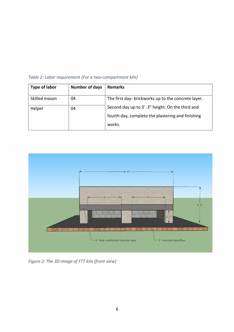
Figure 3: The 3D image of FTT kiln (side top view)
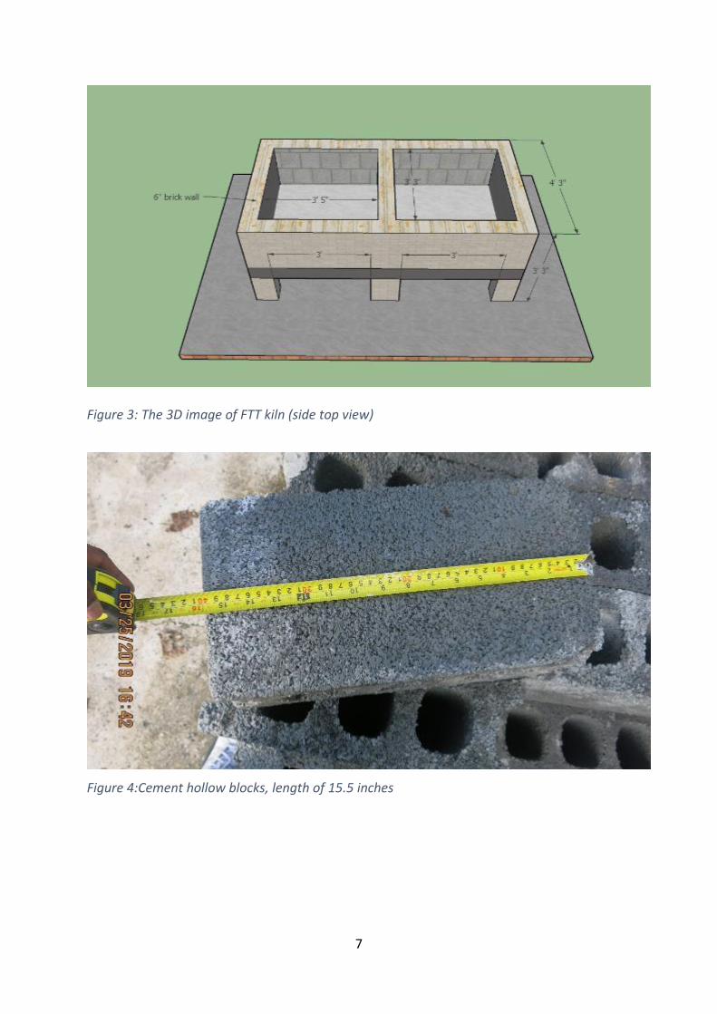
Figure 4:Cement hollow blocks, length of 15.5 inches
8
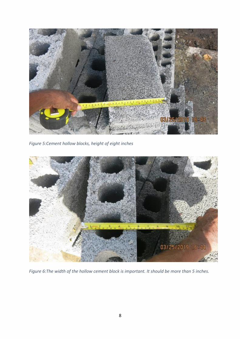
Figure 5:Cement hollow blocks, height of eight inches
Figure 6:The width of the hollow cement block is important. It should be more than 5 inches.
9
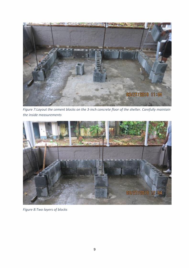
Figure 7:Layout the cement blocks on the 3-inch concrete floor of the shelter. Carefully maintain
the inside measurements
Figure 8:Two layers of blocks
10
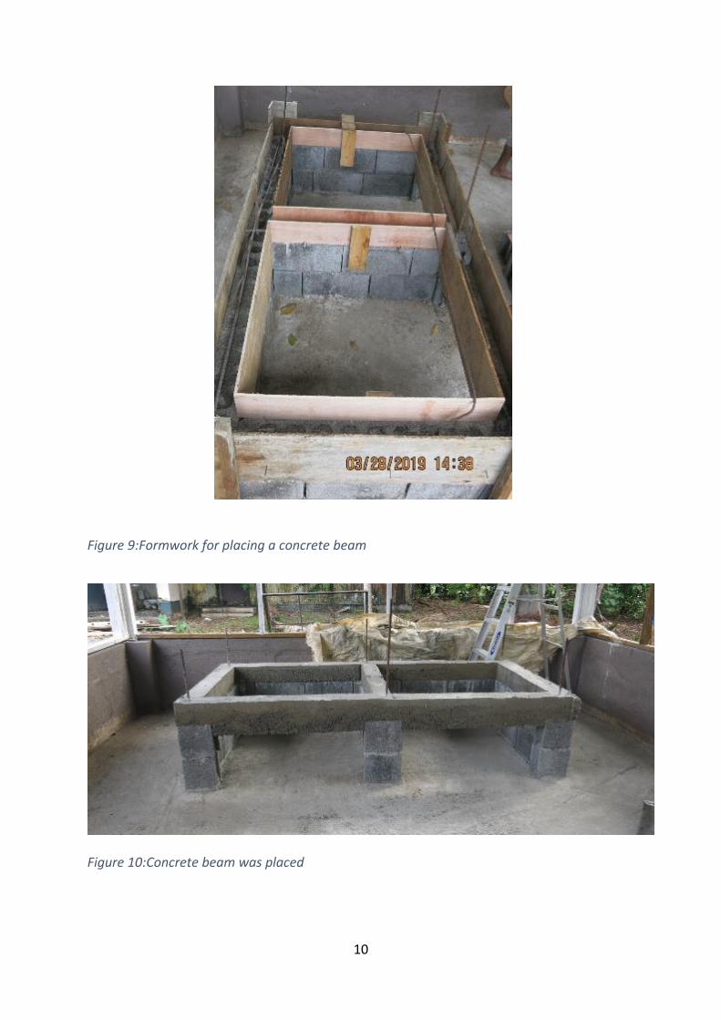
Figure 9:Formwork for placing a concrete beam
Figure 10:Concrete beam was placed
11
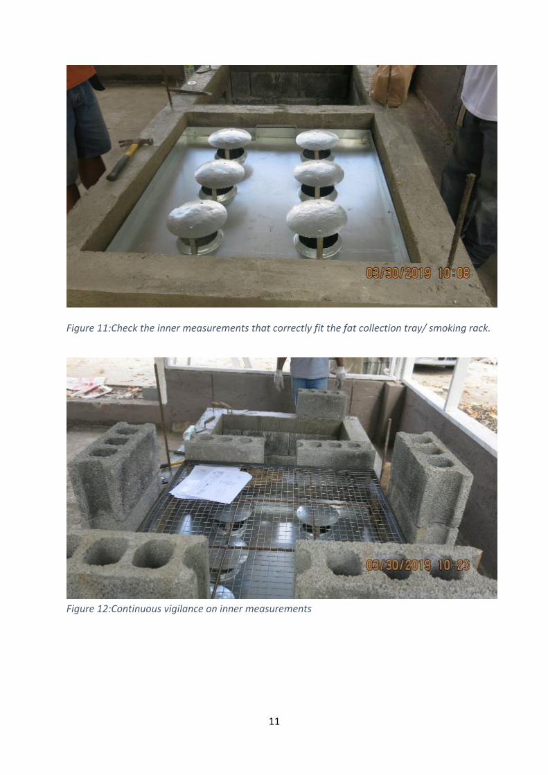
Figure 11:Check the inner measurements that correctly fit the fat collection tray/ smoking rack.
Figure 12:Continuous vigilance on inner measurements
12
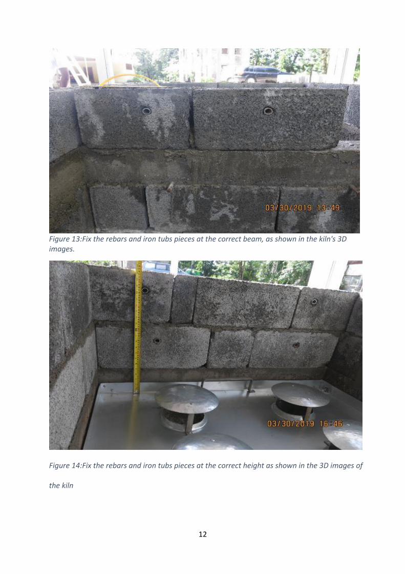
Figure 13:Fix the rebars and iron tubs pieces at the correct beam, as shown in the kiln's 3D images.
Figure 14:Fix the rebars and iron tubs pieces at the correct height as shown in the 3D images of
the kiln
13
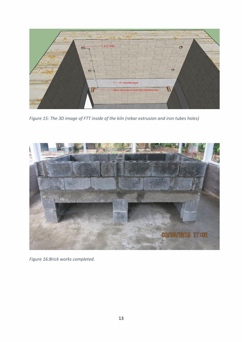
Figure 15: The 3D image of FTT inside of the kiln (rebar extrusion and iron tubes holes)
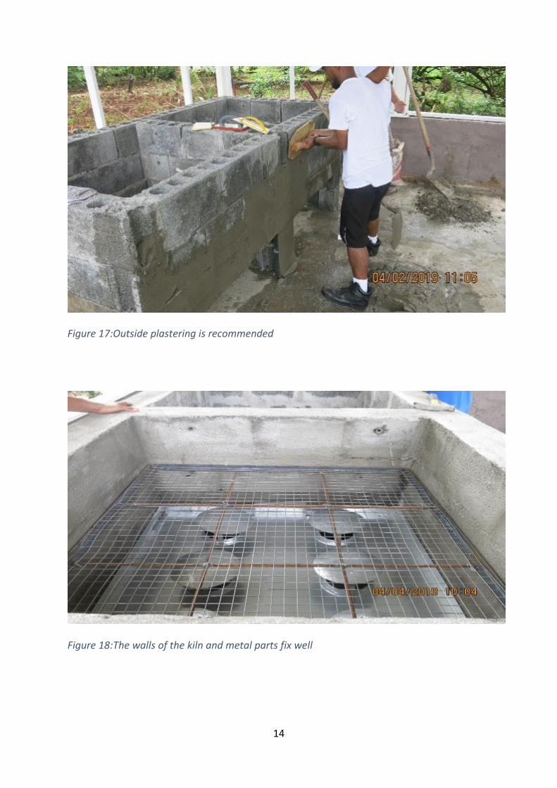
Figure 16:Brick works completed.
14
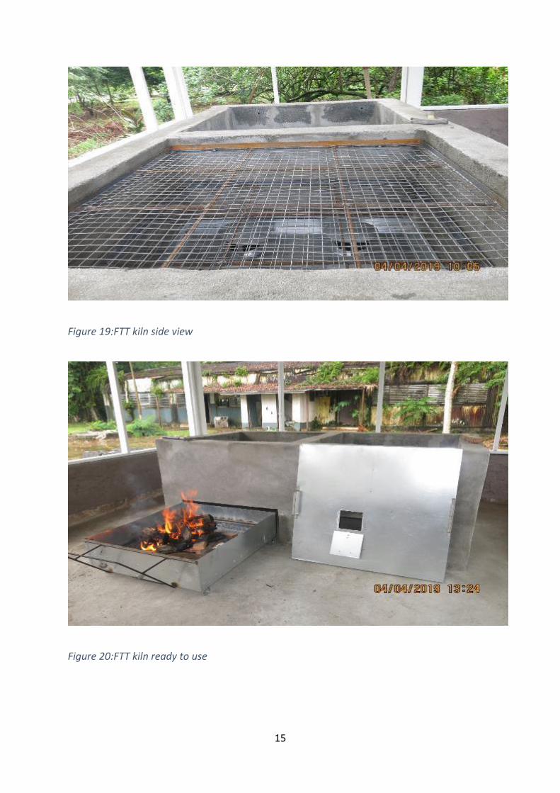
Figure 17:Outside plastering is recommended
Figure 18:The walls of the kiln and metal parts fix well
15
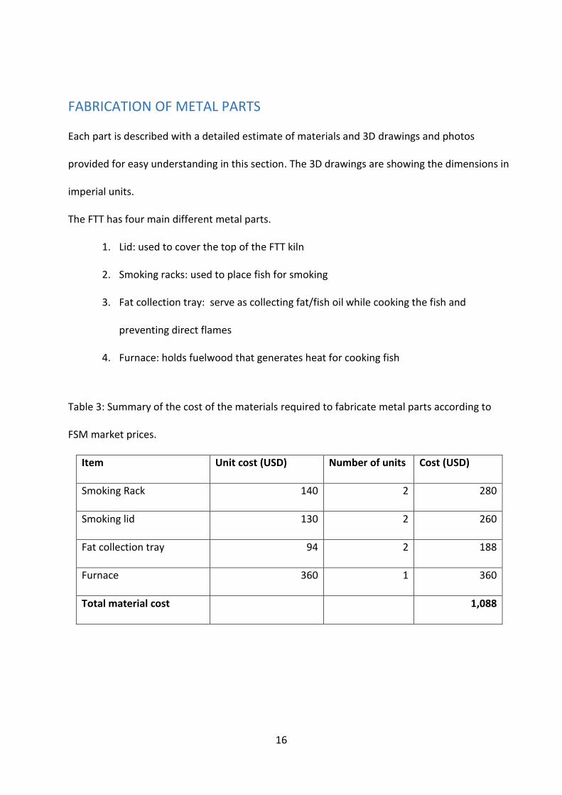
Figure 19:FTT kiln side view
Figure 20:FTT kiln ready to use
16
FABRICATION OF METAL PARTS Each part is described with a detailed estimate of materials and 3D drawings and photos
provided for easy understanding in this section. The 3D drawings are showing the dimensions in
imperial units.
The FTT has four main different metal parts.
1. Lid: used to cover the top of the FTT kiln
2. Smoking racks: used to place fish for smoking
3. Fat collection tray: serve as collecting fat/fish oil while cooking the fish and
preventing direct flames
4. Furnace: holds fuelwood that generates heat for cooking fish
Table 3: Summary of the cost of the materials required to fabricate metal parts according to
FSM market prices.
Item Unit cost (USD) Number of units Cost (USD)
Smoking Rack 140 2 280
Smoking lid 130 2 260
Fat collection tray 94 2 188
Furnace 360 1 360
Total material cost 1,088
17
Table 4: Detailed material list for all metal parts (lid, smoking rack, fat collection tray, and
furnace). (This item list can be used as a bulk purchasing list)
Material Specifications Unit
Unit
cost
(USD)
Quantity
required
Cost
(USD)
Angle iron 1/8"x 1 -1/4inch x 1 -1/4
inch feet 4.0 104
416
Caster wheel 2 1/2-inch size iron made each 10.0 4
40
Flat tin sheet 22 gauge sheet (4'x8') 50.0 1
50
Flat tin sheet 14 gauge sheet (4'x8') 120.0 1
120
Flat tin sheet 16 gauge sheet (4'x8') 70.0 1 70
Hinge 3 inches each 5.0 2 10
Iron pipe 1-inch galvanized pipe feet 4.0 8 32
Iron pipe 1/2-inch galvanized pipe feet 2.0 11 22
Stainless
mesh 1inch x 1-inch x 4 feet linear feet 12.0 8
96
Steel flat iron 1-inch width feet 3.0 16
48
Steel flat iron 1/2-inch width feet 2.0 42
84
Steel mesh 1/2-inch x 1/2 inch steel
mesh Square feet 5.0 20
100
Total
1,088
18
Material selection In this section, a general guideline for the material is given. Each material is recommended
based on its use and durability.
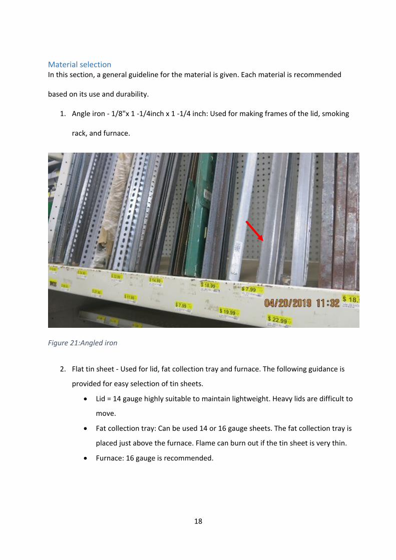
1. Angle iron - 1/8"x 1 -1/4inch x 1 -1/4 inch: Used for making frames of the lid, smoking
rack, and furnace.
Figure 21:Angled iron
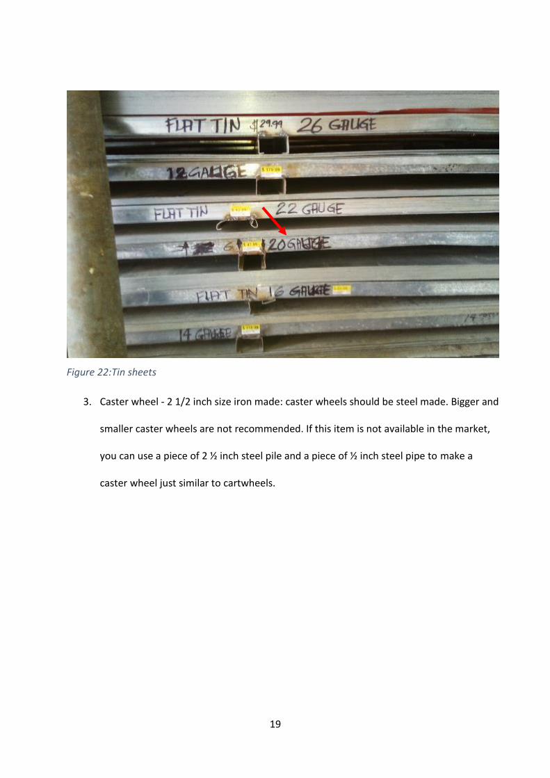
2. Flat tin sheet - Used for lid, fat collection tray and furnace. The following guidance is
provided for easy selection of tin sheets.
Lid = 14 gauge highly suitable to maintain lightweight. Heavy lids are difficult to
move.
Fat collection tray: Can be used 14 or 16 gauge sheets. The fat collection tray is
placed just above the furnace. Flame can burn out if the tin sheet is very thin.
Furnace: 16 gauge is recommended.
19
Figure 22:Tin sheets
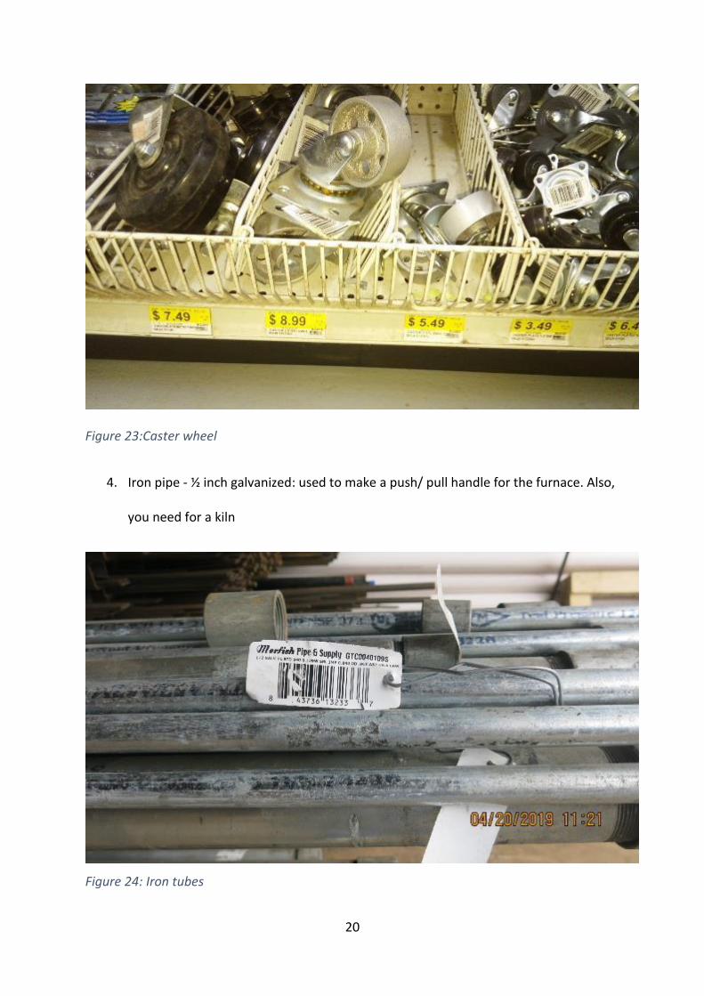
3. Caster wheel - 2 1/2 inch size iron made: caster wheels should be steel made. Bigger and
smaller caster wheels are not recommended. If this item is not available in the market,
you can use a piece of 2 ½ inch steel pile and a piece of ½ inch steel pipe to make a
caster wheel just similar to cartwheels.
20
Figure 23:Caster wheel
4. Iron pipe - ½ inch galvanized: used to make a push/ pull handle for the furnace. Also,
you need for a kiln
Figure 24: Iron tubes
21
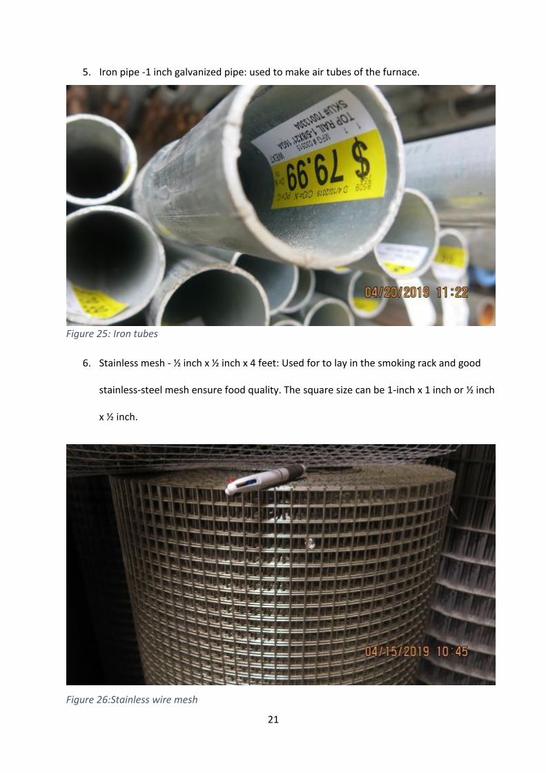
5. Iron pipe -1 inch galvanized pipe: used to make air tubes of the furnace.
Figure 25: Iron tubes
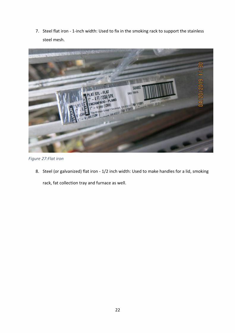
6. Stainless mesh - ½ inch x ½ inch x 4 feet: Used for to lay in the smoking rack and good
stainless-steel mesh ensure food quality. The square size can be 1-inch x 1 inch or ½ inch
x ½ inch.
Figure 26:Stainless wire mesh
22
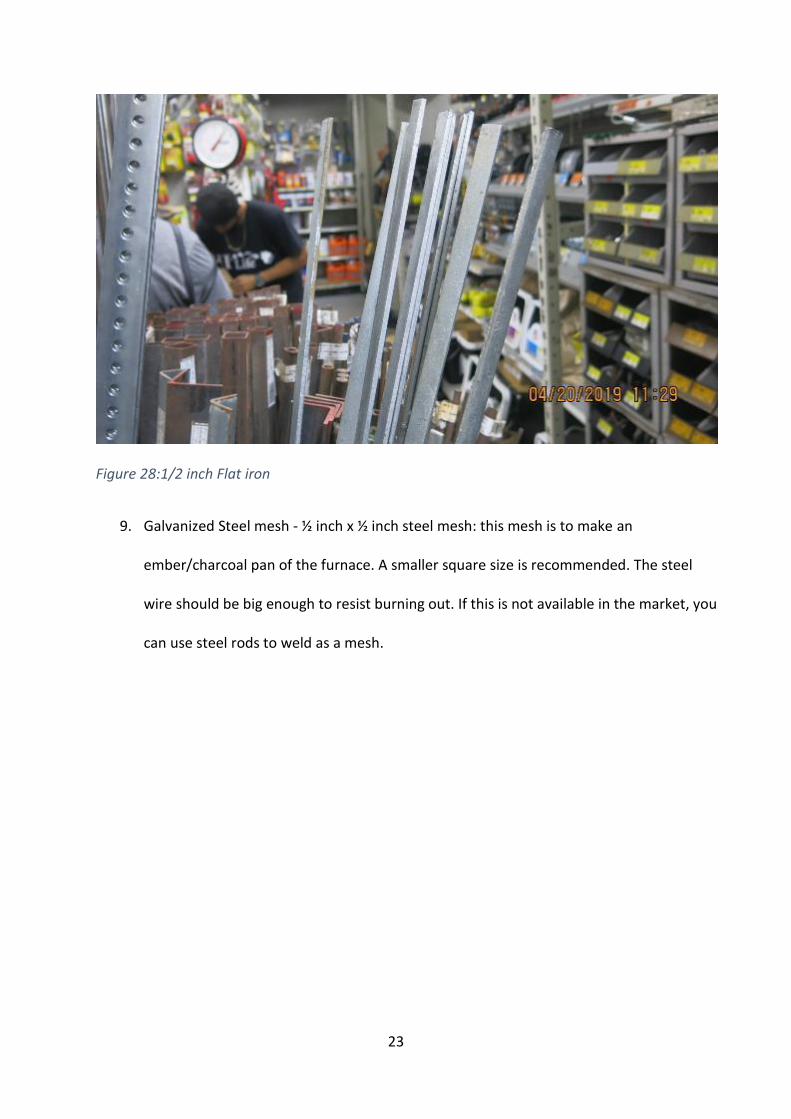
7. Steel flat iron - 1-inch width: Used to fix in the smoking rack to support the stainless
steel mesh.
Figure 27:Flat iron
8. Steel (or galvanized) flat iron - 1/2 inch width: Used to make handles for a lid, smoking
rack, fat collection tray and furnace as well.
23
Figure 28:1/2 inch Flat iron
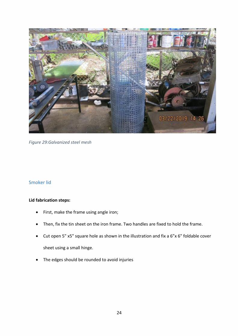
9. Galvanized Steel mesh - ½ inch x ½ inch steel mesh: this mesh is to make an
ember/charcoal pan of the furnace. A smaller square size is recommended. The steel
wire should be big enough to resist burning out. If this is not available in the market, you
can use steel rods to weld as a mesh.
24
Figure 29:Galvanized steel mesh
Smoker lid
Lid fabrication steps:
First, make the frame using angle iron;
Then, fix the tin sheet on the iron frame. Two handles are fixed to hold the frame.
Cut open 5" x5" square hole as shown in the illustration and fix a 6”x 6" foldable cover
sheet using a small hinge.
The edges should be rounded to avoid injuries
25
Table 5: Material requirement for one unit of the lid
Material Specifications Unit
Unit cost
(USD)
quantity
required
Cost
(USD)
Angle iron
1/8inch x 1 -1/4inch x
1 -1/4 inch feet 4.0 24 96.0
Flat tin
sheet 22 gauge
sheet
(4'x8') 50.0 0.5 25.0
Steel flat
iron 1/2-inch width feet 2.0 2 4.0
Hinge 3 inches each 5.0 1 5.0
Total 130.0
Table 6: Labor requirement to fabricate one unit
Type of labor Number of days Remarks
Skilled welder 01 maximum 01-day
Helper 01 maximum 01-day
26
Figure 30: 3D view of the lid – Isometric view
Figure 31:Lid frame (First step)
27
Figure 32:Completed lid (fix the tin sheet on the iron frame)
Figure 33:Fixing the handle of the lid
28
Figure 34:Completed lid
Smoking Rack Smoking racks made with steel is better placed inside the kiln chamber. If it is necessary to increase the processing capacity, wooden framed smoking racks can be made. Such wooden racks can be stacked over the kiln chamber. Construction steps:
First, make the metal frame using the stainless angle iron in case of metal racks;
The wooden frames can be made with durable heat resist wood (2 inch x4inch size
wood)
Fix the stainless-steel mesh to the frame.
29
Table 7: Material requirement for a smoking rack
Material Specifications Unit
Unit cost
(USD)
Quantity
required
Cost
(USD)
Angle iron
1/8 inch x 1 -1/4inch x 1 -
1/4 inch feet 4.0 16 64.0
Steel flat
iron 1-inch width feet 3.0 8 24.0
Steel flat
iron 1/2-inch width feet 2.0 2 4.0
Stainless
mesh 1inch x 1-inch x 4 feet
linear
feet 12.0 4 48.0
Total 140.0
Table 8: Labor requirement for fabricating two units of smoking racks
Type of labor Number of days
Skilled welder 01
Helper 01
30
Figure 35:3D view of the smoking rack – Isometric view
Figure 36:Completed smoking rack
31
Figure 37: Smoking rack is placed above the fat collection tray
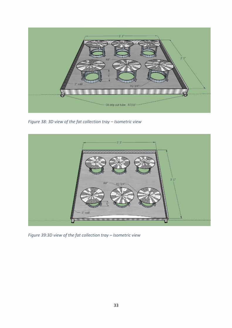
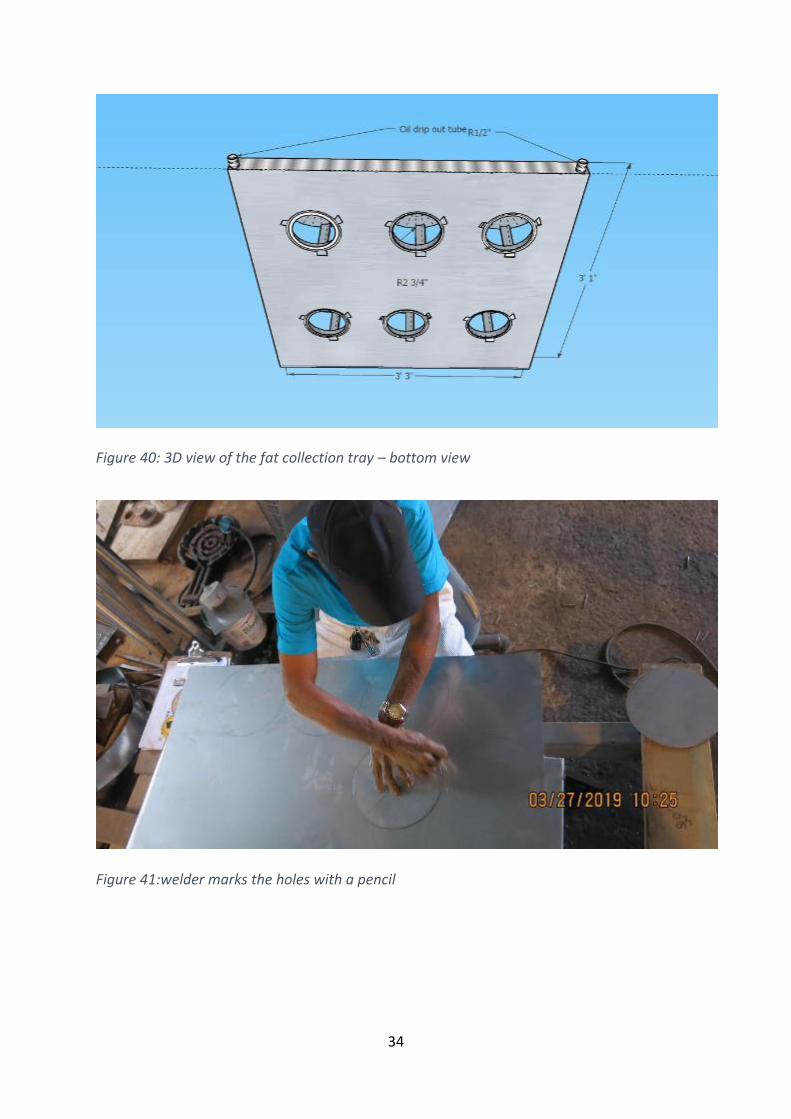
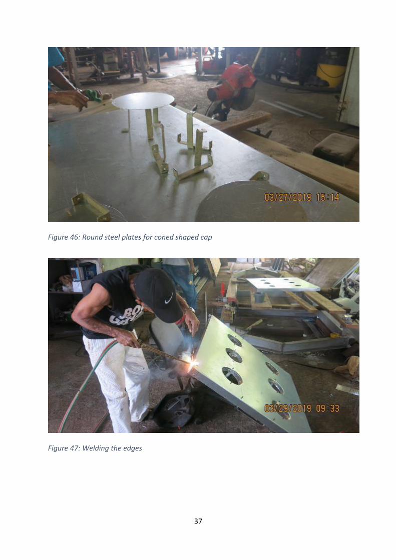
Fat collection tray Construction steps:
First, mark the six holes (2.5-inch radius) on the tin sheet. Each raw has three holes and maintain the same distance
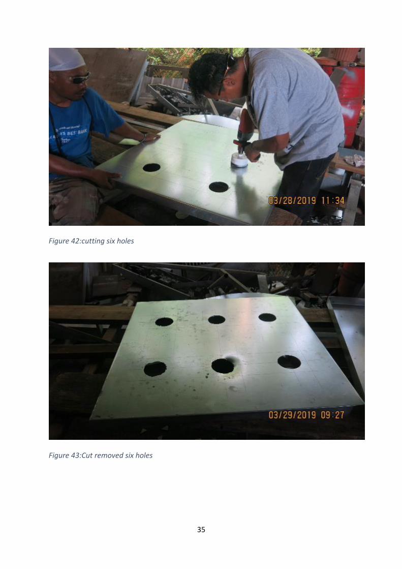
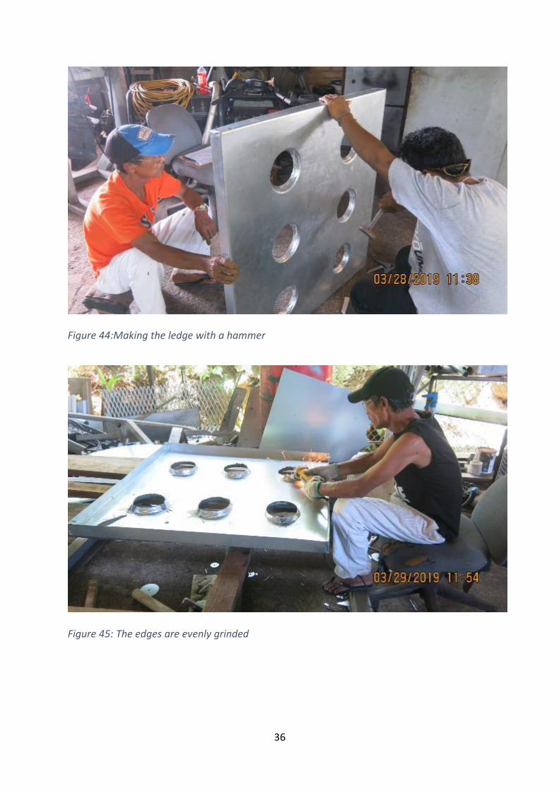
Cut remove the holes. Then, set the upward ledge using a hammer and grind the edges evenly
Cut six number of 8-inch round plates and make the cone-shaped cap.
Fix those cones shaped cup using ½-inch plat iron as shown in figure 47
32
Table 9: Material requirement for one unit of fat collection tray
Material Specifications Unit
Unit cost
(USD)
Quantity
required
Cost
(USD)
Flat tin sheet 14 gauge
Square
Feet 2.72 22 60.0
Steel flat
iron 1/2-inch width feet 2.0 16 32.0
Iron pipe
1/2 - inch
galvanized feet 2.0 1 2.0
Total 94.0
Table 10: Labor requirement (to fabricate two units of fat collection trays)
Type of labor Number of days
Skilled welder 04
Helper 04
33
Figure 38: 3D view of the fat collection tray – Isometric view
Figure 39:3D view of the fat collection tray – Isometric view
34
Figure 40: 3D view of the fat collection tray – bottom view
Figure 41:welder marks the holes with a pencil
35
Figure 42:cutting six holes
Figure 43:Cut removed six holes
36
Figure 44:Making the ledge with a hammer
Figure 45: The edges are evenly grinded
37
Figure 46: Round steel plates for coned shaped cap
Figure 47: Welding the edges
38
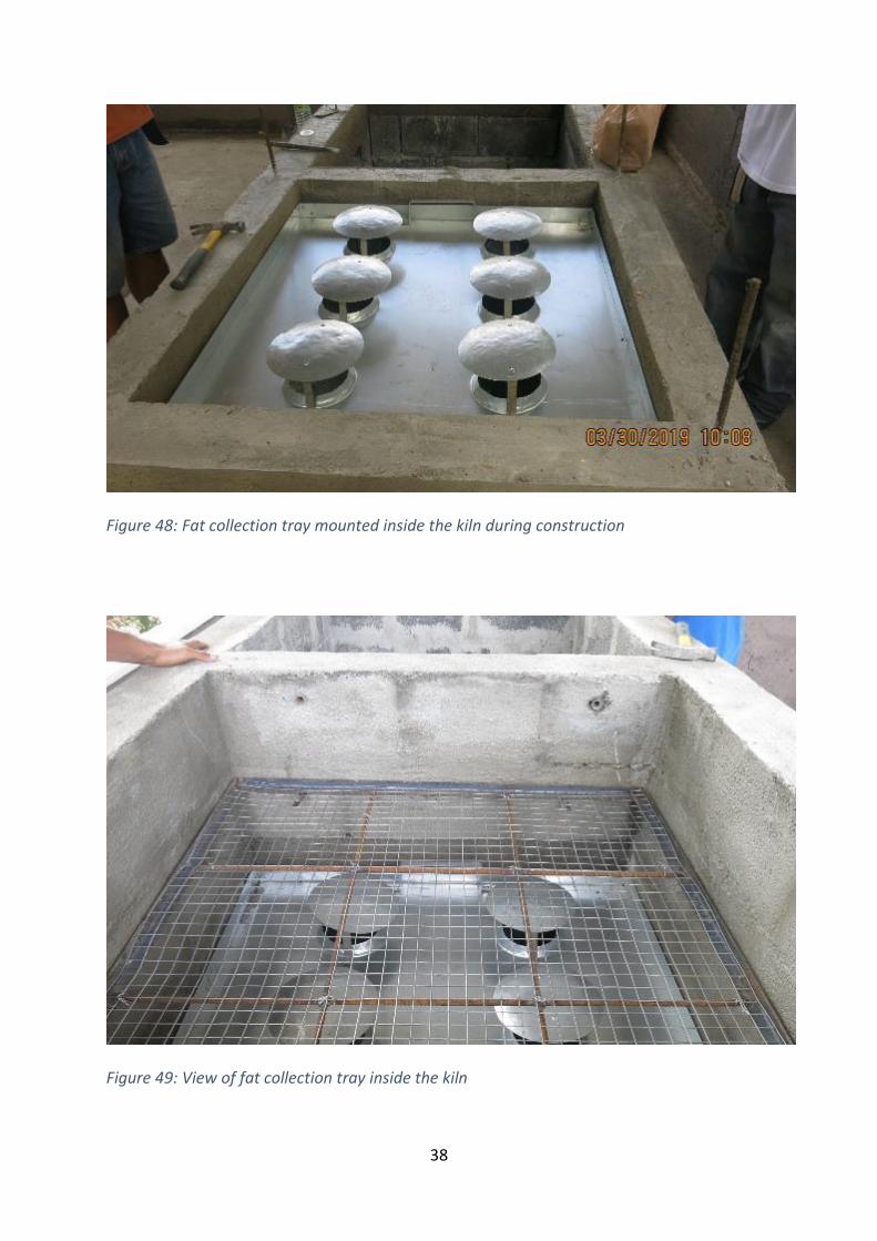
Figure 48: Fat collection tray mounted inside the kiln during construction
Figure 49: View of fat collection tray inside the kiln

39
Furnace
Construction steps:
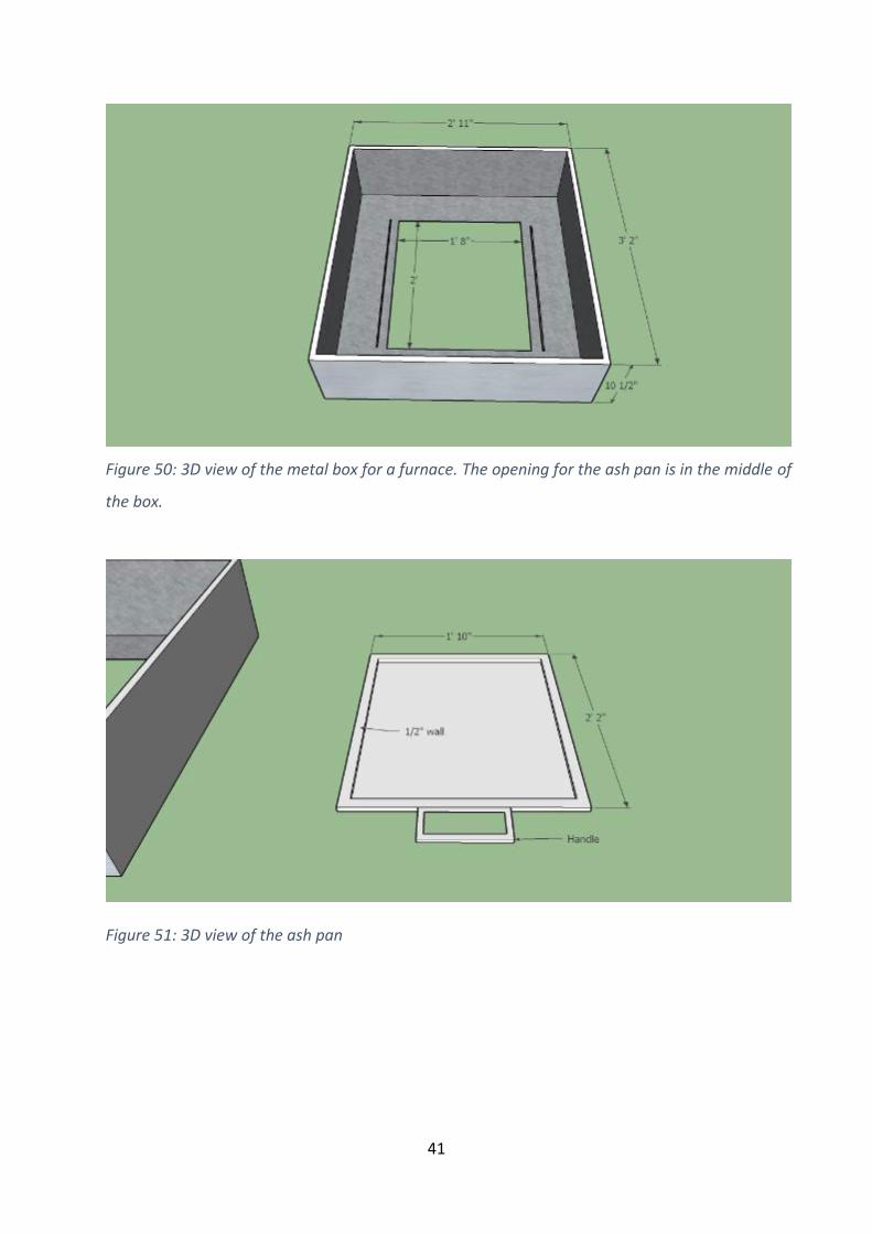
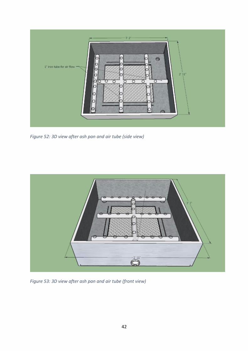
Fabricate the furnace box (2’11”x2’2”x10.5”) with the 16-gauge tin sheet
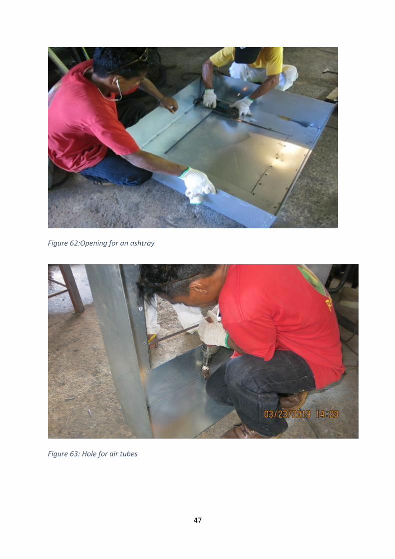
Cut remove 1’8” x 2’ hole from the bottom of the box where fuelwood ash will fall
Make the air tubes using ½ inch iron tubes as shown in figure 63 and fix the inlet to the
front side
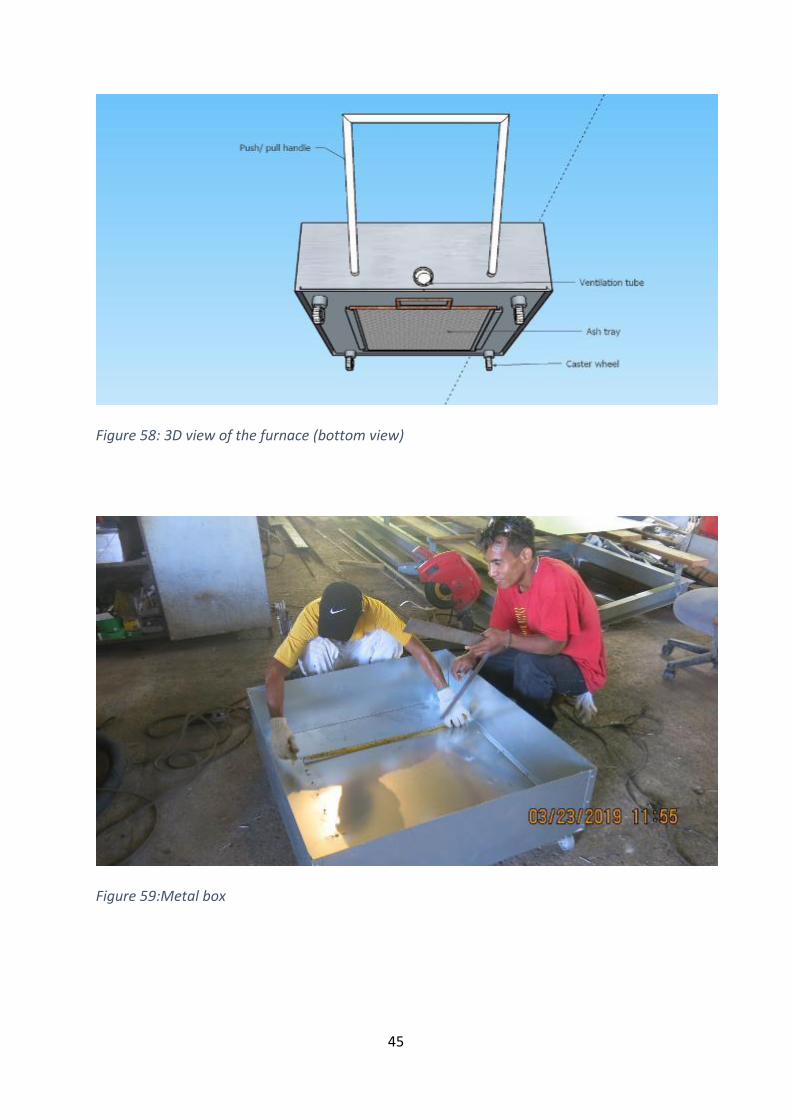
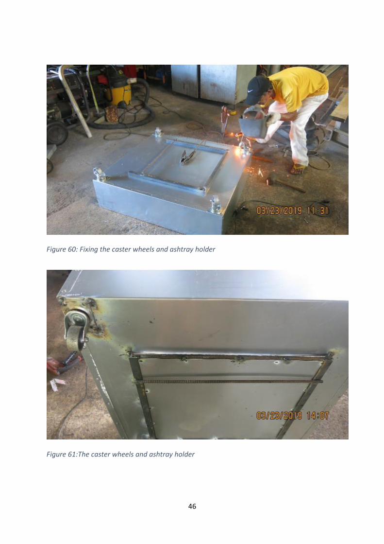
Fix as pan to the bottom of the furnace using an angle iron (Figure 60).
Caster wheels are fixed into the four corners.
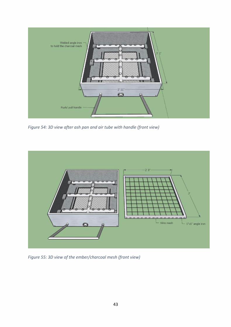
Push/ Pull handle is made with a 1-inch iron tube. The handle should be waist height for
easy operation
40
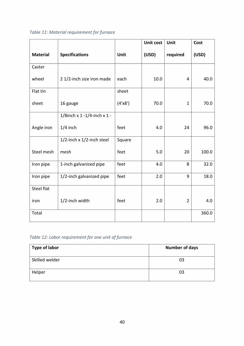
Table 11: Material requirement for furnace
Material Specifications Unit
Unit cost
(USD)
Unit
required
Cost
(USD)
Caster
wheel 2 1/2-inch size iron made each 10.0 4 40.0
Flat tin
sheet 16 gauge
sheet
(4'x8') 70.0 1 70.0
Angle iron
1/8inch x 1 -1/4-inch x 1 -
1/4 inch feet 4.0 24 96.0
Steel mesh
1/2-inch x 1/2-inch steel
mesh
Square
feet 5.0 20 100.0
Iron pipe 1-inch galvanized pipe feet 4.0 8 32.0
Iron pipe 1/2-inch galvanized pipe feet 2.0 9 18.0
Steel flat
iron 1/2-inch width feet 2.0 2 4.0
Total 360.0
Table 12: Labor requirement for one unit of furnace
Type of labor Number of days
Skilled welder 03
Helper 03
41
Figure 50: 3D view of the metal box for a furnace. The opening for the ash pan is in the middle of
the box.
Figure 51: 3D view of the ash pan
42
Figure 52: 3D view after ash pan and air tube (side view)
Figure 53: 3D view after ash pan and air tube (front view)
43
Figure 54: 3D view after ash pan and air tube with handle (front view)
Figure 55: 3D view of the ember/charcoal mesh (front view)
44
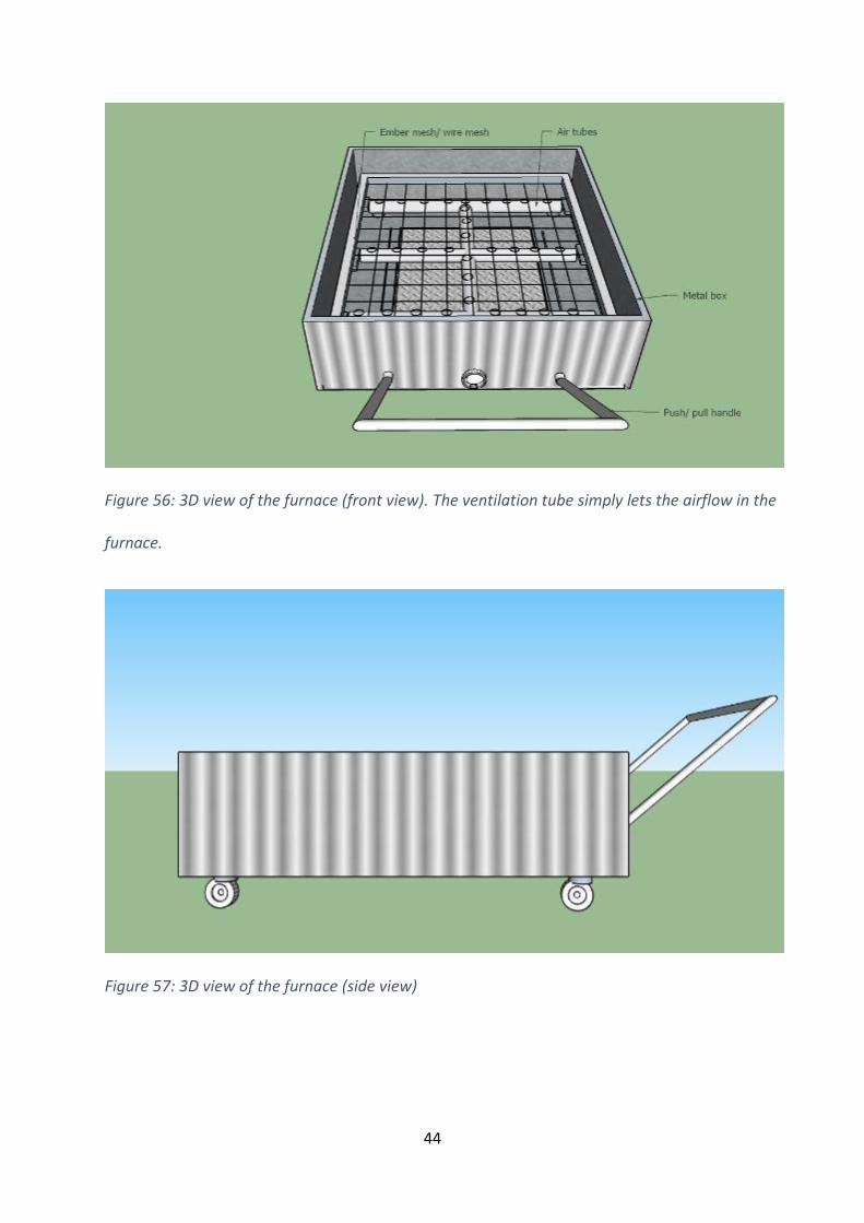
Figure 56: 3D view of the furnace (front view). The ventilation tube simply lets the airflow in the
furnace.
Figure 57: 3D view of the furnace (side view)
45
Figure 58: 3D view of the furnace (bottom view)
Figure 59:Metal box
46
Figure 60: Fixing the caster wheels and ashtray holder
Figure 61:The caster wheels and ashtray holder
47
Figure 62:Opening for an ashtray
Figure 63: Hole for air tubes
48
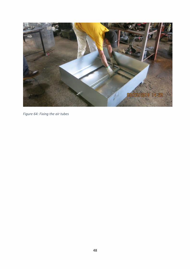
Figure 64: Fixing the air tubes
49
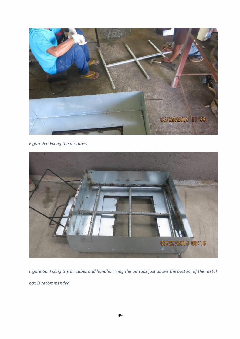
Figure 65: Fixing the air tubes
Figure 66: Fixing the air tubes and handle. Fixing the air tubs just above the bottom of the metal
box is recommended
50
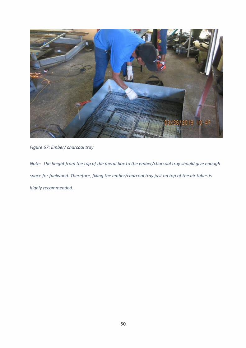
Figure 67: Ember/ charcoal tray
Note: The height from the top of the metal box to the ember/charcoal tray should give enough
space for fuelwood. Therefore, fixing the ember/charcoal tray just on top of the air tubes is
highly recommended.
51
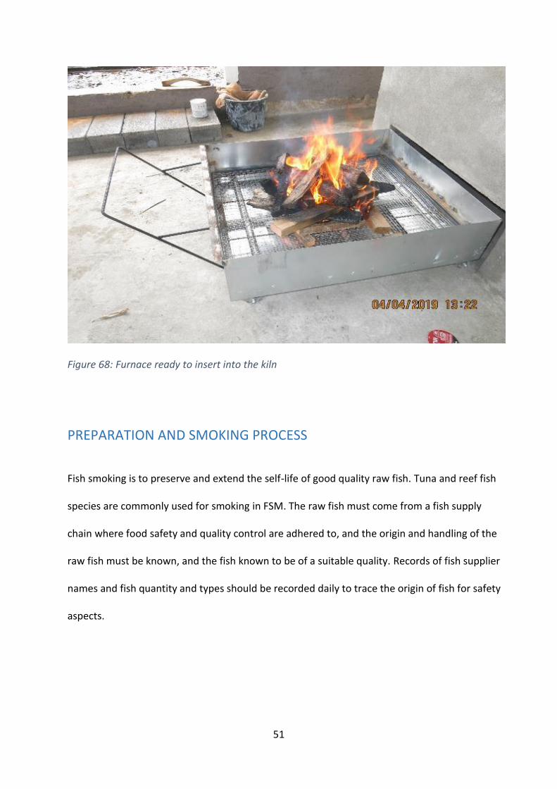
Figure 68: Furnace ready to insert into the kiln
PREPARATION AND SMOKING PROCESS
Fish smoking is to preserve and extend the self-life of good quality raw fish. Tuna and reef fish
species are commonly used for smoking in FSM. The raw fish must come from a fish supply
chain where food safety and quality control are adhered to, and the origin and handling of the
raw fish must be known, and the fish known to be of a suitable quality. Records of fish supplier
names and fish quantity and types should be recorded daily to trace the origin of fish for safety
aspects.
52
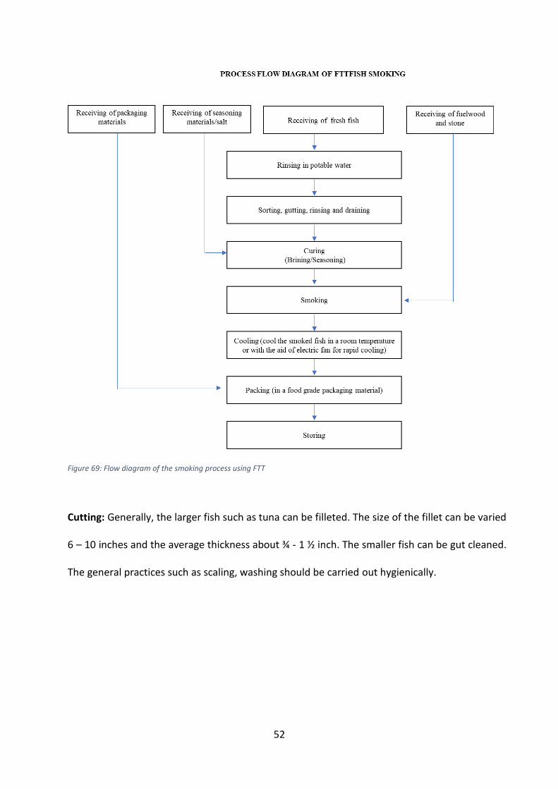
Figure 69: Flow diagram of the smoking process using FTT
Cutting: Generally, the larger fish such as tuna can be filleted. The size of the fillet can be varied
6 – 10 inches and the average thickness about ¾ - 1 ½ inch. The smaller fish can be gut cleaned.
The general practices such as scaling, washing should be carried out hygienically.
53
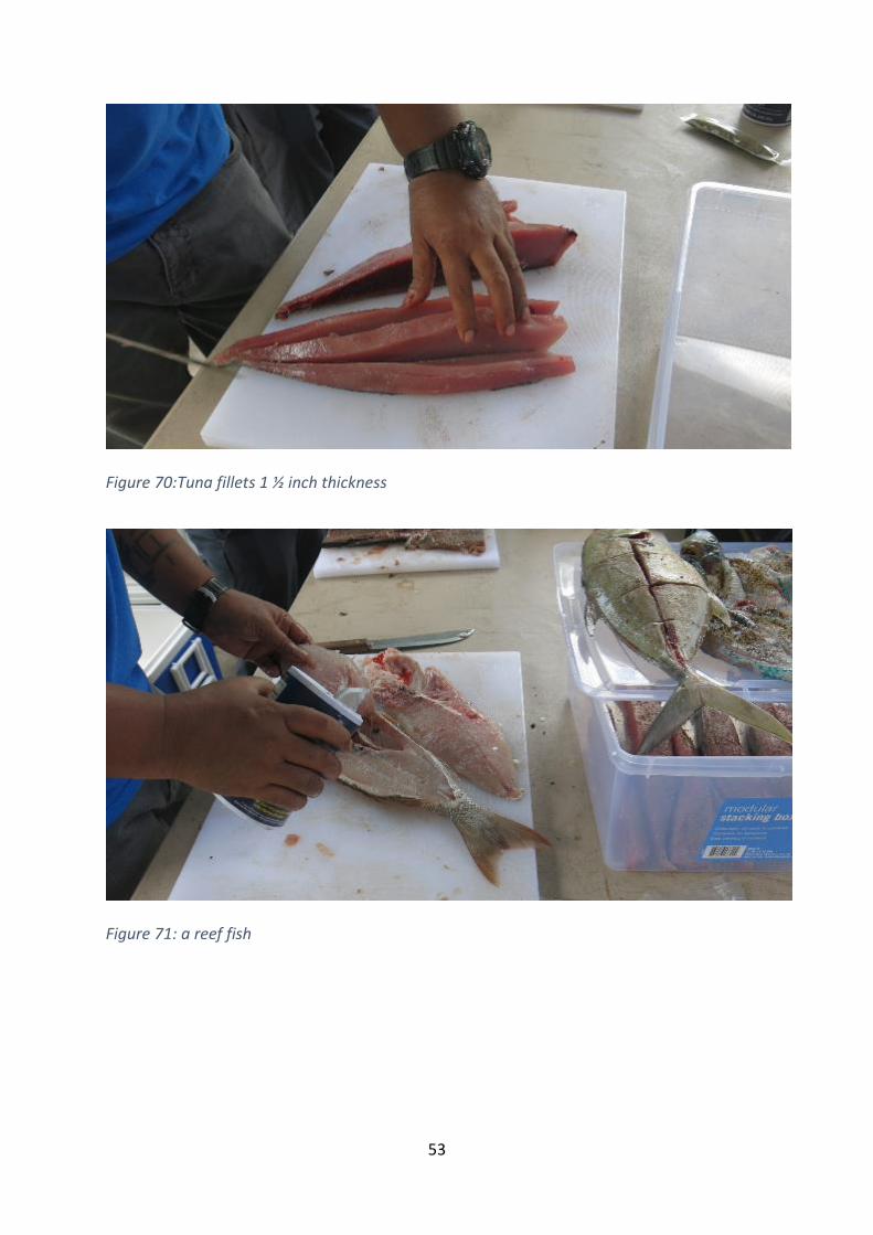
Figure 70:Tuna fillets 1 ½ inch thickness
Figure 71: a reef fish
54
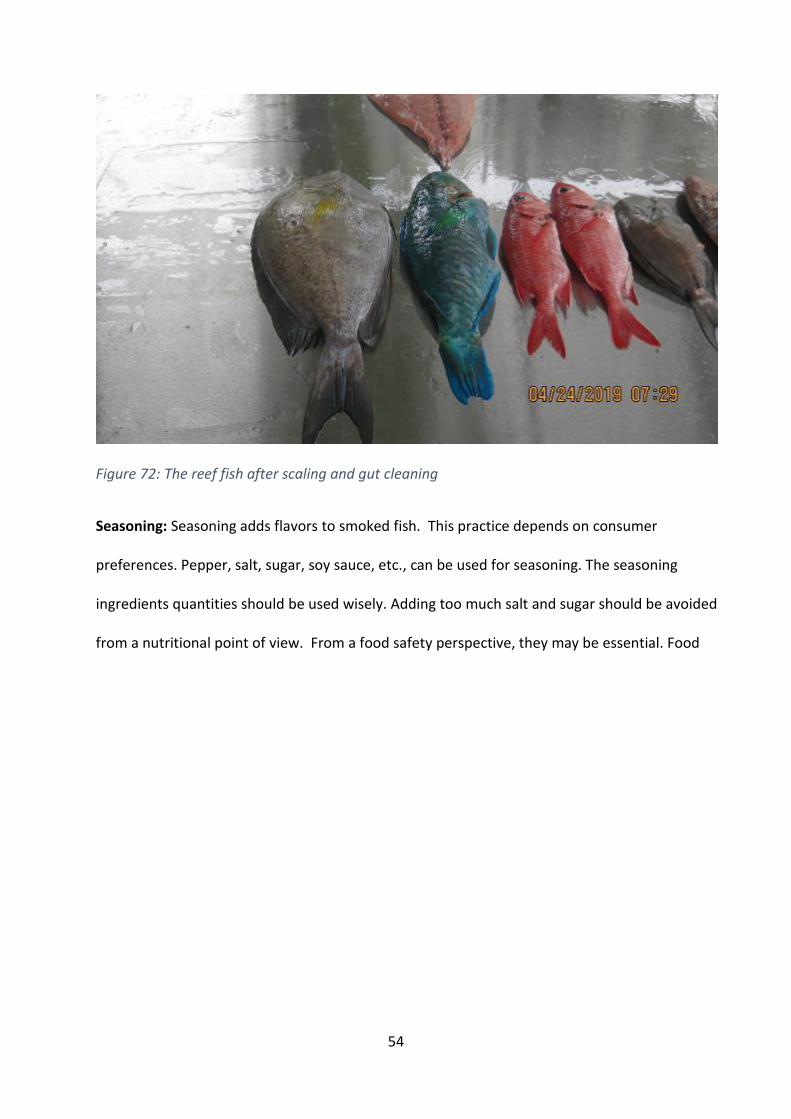
Figure 72: The reef fish after scaling and gut cleaning
Seasoning: Seasoning adds flavors to smoked fish. This practice depends on consumer
preferences. Pepper, salt, sugar, soy sauce, etc., can be used for seasoning. The seasoning
ingredients quantities should be used wisely. Adding too much salt and sugar should be avoided
from a nutritional point of view. From a food safety perspective, they may be essential. Food
55
safety takes precedence here.
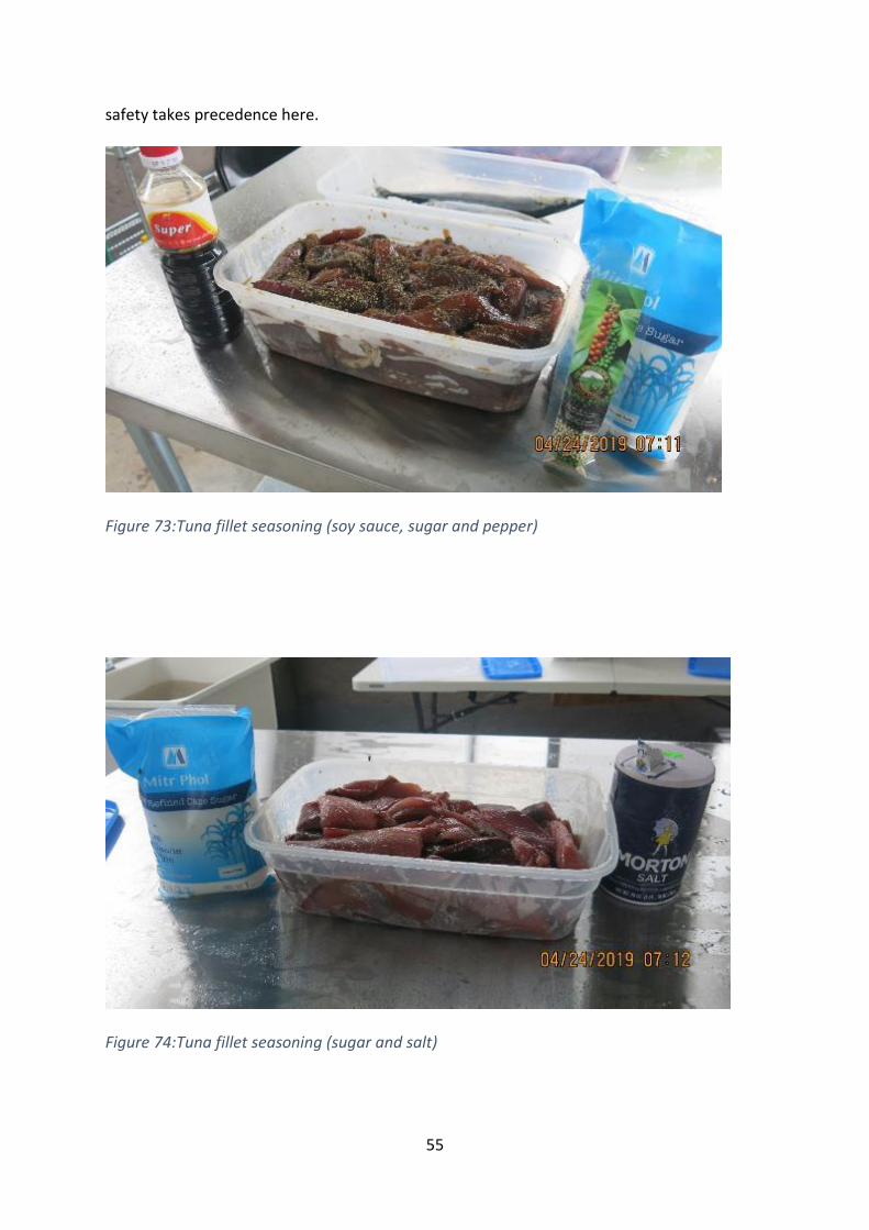
Figure 73:Tuna fillet seasoning (soy sauce, sugar and pepper)
Figure 74:Tuna fillet seasoning (sugar and salt)
56
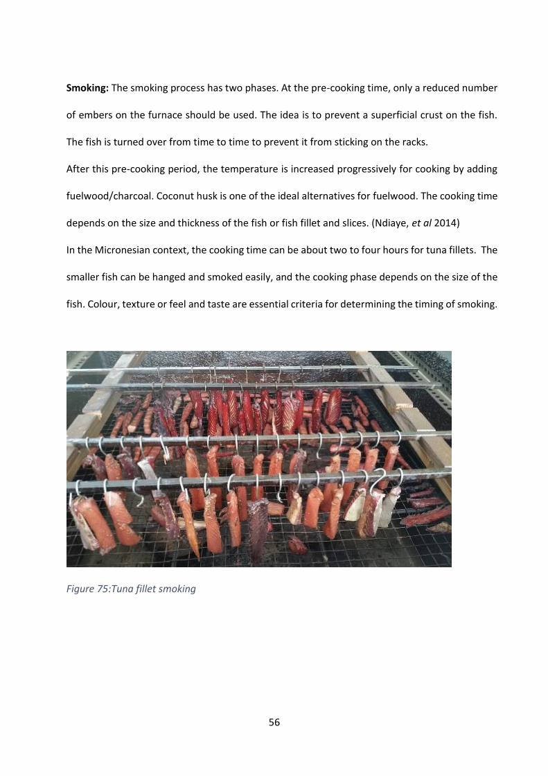
Smoking: The smoking process has two phases. At the pre-cooking time, only a reduced number
of embers on the furnace should be used. The idea is to prevent a superficial crust on the fish.
The fish is turned over from time to time to prevent it from sticking on the racks.
After this pre-cooking period, the temperature is increased progressively for cooking by adding
fuelwood/charcoal. Coconut husk is one of the ideal alternatives for fuelwood. The cooking time
depends on the size and thickness of the fish or fish fillet and slices. (Ndiaye, et al 2014)
In the Micronesian context, the cooking time can be about two to four hours for tuna fillets. The
smaller fish can be hanged and smoked easily, and the cooking phase depends on the size of the
fish. Colour, texture or feel and taste are essential criteria for determining the timing of smoking.
Figure 75:Tuna fillet smoking
57
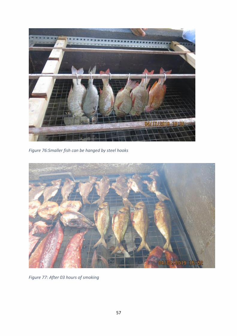
Figure 76:Smaller fish can be hanged by steel hooks
Figure 77: After 03 hours of smoking
58
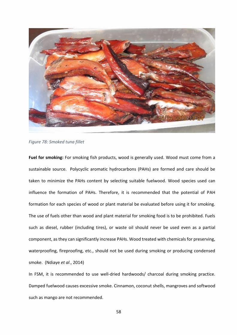
Figure 78: Smoked tuna fillet
Fuel for smoking: For smoking fish products, wood is generally used. Wood must come from a
sustainable source. Polycyclic aromatic hydrocarbons (PAHs) are formed and care should be
taken to minimize the PAHs content by selecting suitable fuelwood. Wood species used can
influence the formation of PAHs. Therefore, it is recommended that the potential of PAH
formation for each species of wood or plant material be evaluated before using it for smoking.
The use of fuels other than wood and plant material for smoking food is to be prohibited. Fuels
such as diesel, rubber (including tires), or waste oil should never be used even as a partial
component, as they can significantly increase PAHs. Wood treated with chemicals for preserving,
waterproofing, fireproofing, etc., should not be used during smoking or producing condensed
smoke. (Ndiaye et al., 2014)
In FSM, it is recommended to use well-dried hardwoods/ charcoal during smoking practice.
Damped fuelwood causes excessive smoke. Cinnamon, coconut shells, mangroves and softwood
such as mango are not recommended.
59
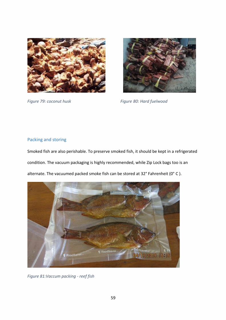
Figure 79: coconut husk Figure 80: Hard fuelwood
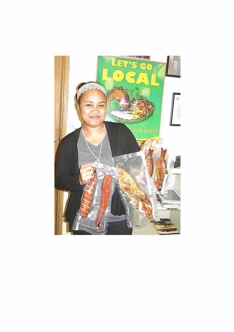
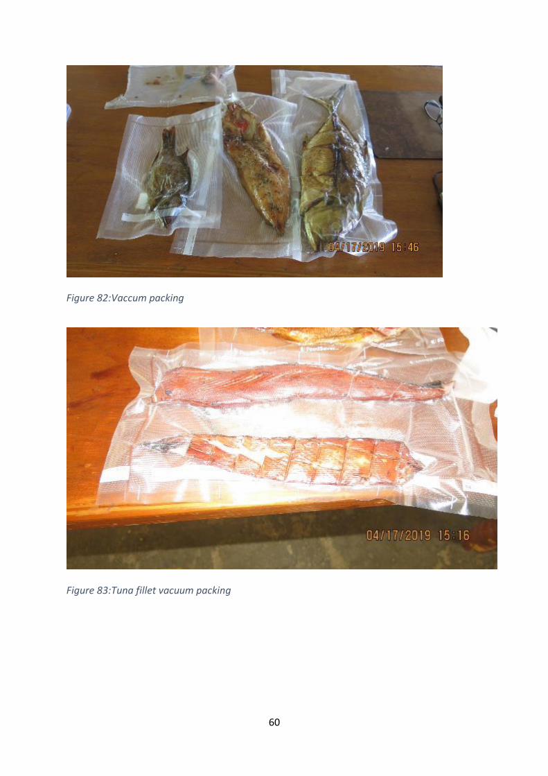
Packing and storing Smoked fish are also perishable. To preserve smoked fish, it should be kept in a refrigerated
condition. The vacuum packaging is highly recommended, while Zip Lock bags too is an
alternate. The vacuumed packed smoke fish can be stored at 32° Fahrenheit (0° C ).
Figure 81:Vaccum packing - reef fish
60
Figure 82:Vaccum packing
Figure 83:Tuna fillet vacuum packing
61
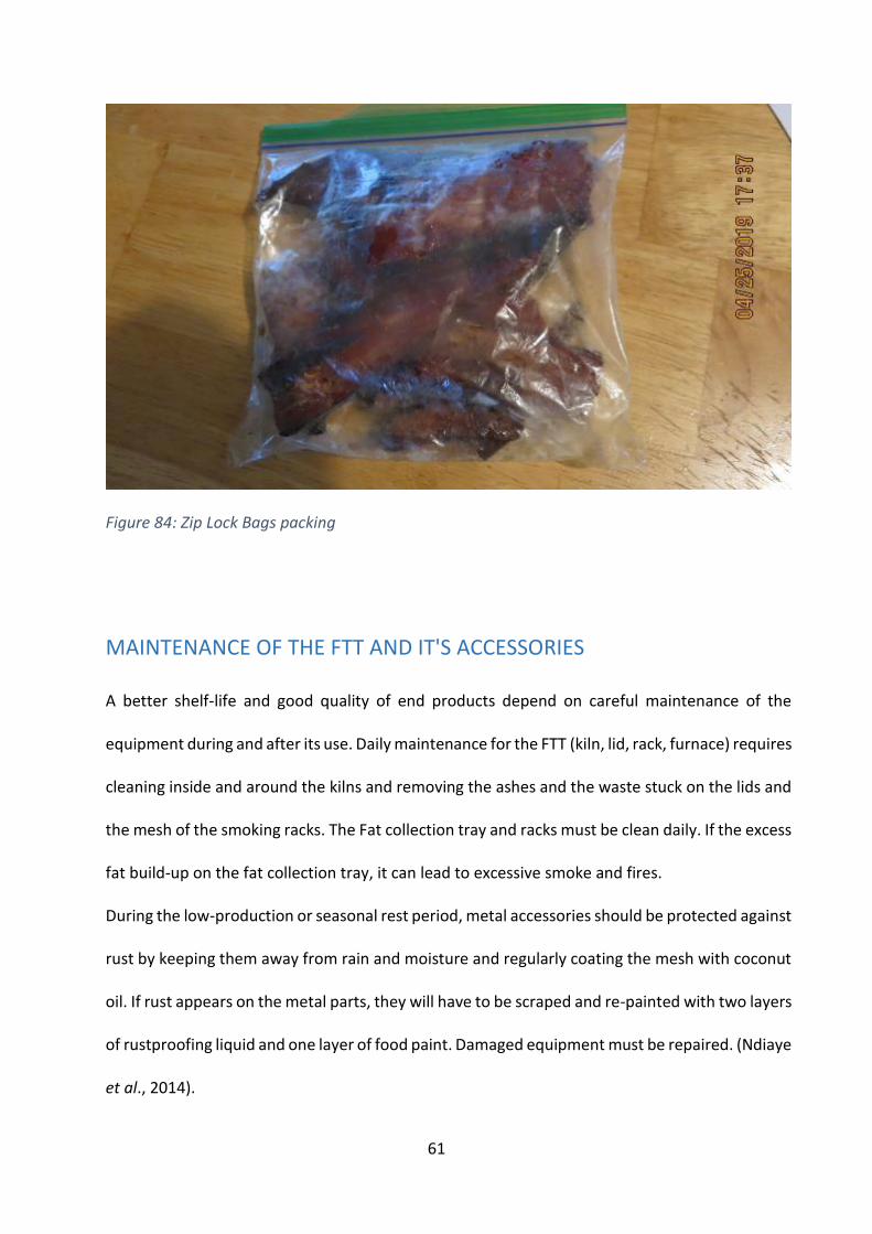
Figure 84: Zip Lock Bags packing
MAINTENANCE OF THE FTT AND IT'S ACCESSORIES A better shelf-life and good quality of end products depend on careful maintenance of the
equipment during and after its use. Daily maintenance for the FTT (kiln, lid, rack, furnace) requires
cleaning inside and around the kilns and removing the ashes and the waste stuck on the lids and
the mesh of the smoking racks. The Fat collection tray and racks must be clean daily. If the excess
fat build-up on the fat collection tray, it can lead to excessive smoke and fires.
During the low-production or seasonal rest period, metal accessories should be protected against
rust by keeping them away from rain and moisture and regularly coating the mesh with coconut
oil. If rust appears on the metal parts, they will have to be scraped and re-painted with two layers
of rustproofing liquid and one layer of food paint. Damaged equipment must be repaired. (Ndiaye
et al., 2014).
62
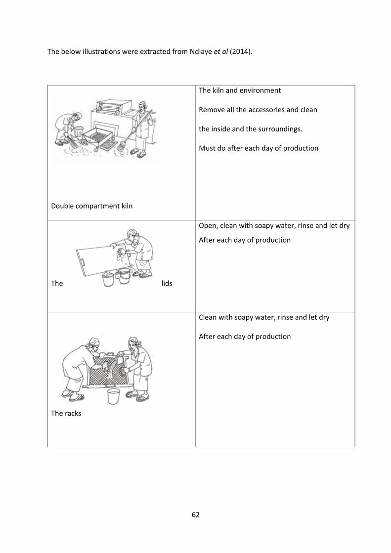
The below illustrations were extracted from Ndiaye et al (2014).
Double compartment kiln
The kiln and environment
Remove all the accessories and clean
the inside and the surroundings.
Must do after each day of production
The lids
Open, clean with soapy water, rinse and let dry
After each day of production
The racks
Clean with soapy water, rinse and let dry
After each day of production
63
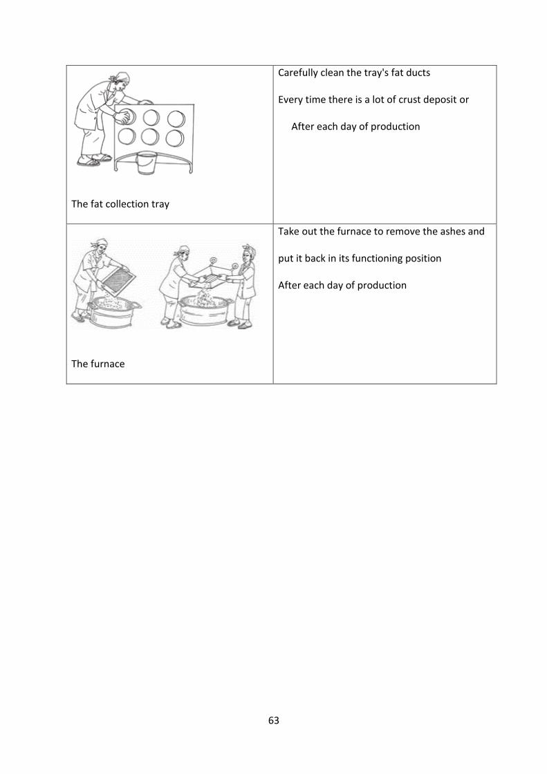
The fat collection tray
Carefully clean the tray's fat ducts
Every time there is a lot of crust deposit or
After each day of production
The furnace
Take out the furnace to remove the ashes and
put it back in its functioning position
After each day of production
64
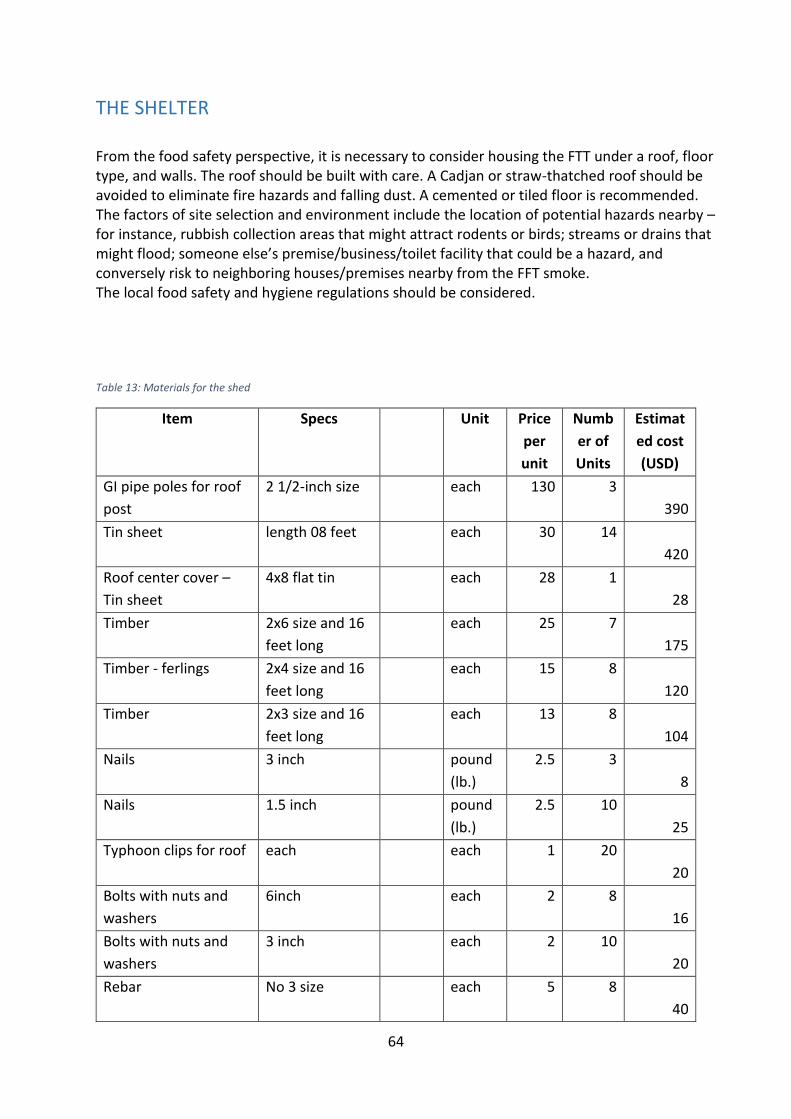
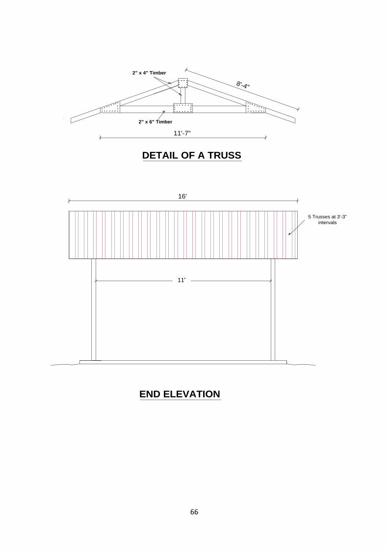
THE SHELTER From the food safety perspective, it is necessary to consider housing the FTT under a roof, floor type, and walls. The roof should be built with care. A Cadjan or straw-thatched roof should be avoided to eliminate fire hazards and falling dust. A cemented or tiled floor is recommended. The factors of site selection and environment include the location of potential hazards nearby – for instance, rubbish collection areas that might attract rodents or birds; streams or drains that might flood; someone else’s premise/business/toilet facility that could be a hazard, and conversely risk to neighboring houses/premises nearby from the FFT smoke. The local food safety and hygiene regulations should be considered. Table 13: Materials for the shed
Item Specs Unit Price
per
unit
Numb
er of
Units
Estimat
ed cost
(USD)
GI pipe poles for roof
post
2 1/2-inch size each 130 3
390
Tin sheet length 08 feet each 30 14
420
Roof center cover –
Tin sheet
4x8 flat tin each 28 1
28
Timber 2x6 size and 16
feet long
each 25 7
175
Timber - ferlings 2x4 size and 16
feet long
each 15 8
120
Timber 2x3 size and 16
feet long
each 13 8
104
Nails 3 inch pound
(lb.)
2.5 3
8
Nails 1.5 inch pound
(lb.)
2.5 10
25
Typhoon clips for roof each each 1 20
20
Bolts with nuts and
washers
6inch each 2 8
16
Bolts with nuts and
washers
3 inch each 2 10
20
Rebar No 3 size each 5 8
40
65
Item Specs Unit Price
per
unit
Numb
er of
Units
Estimat
ed cost
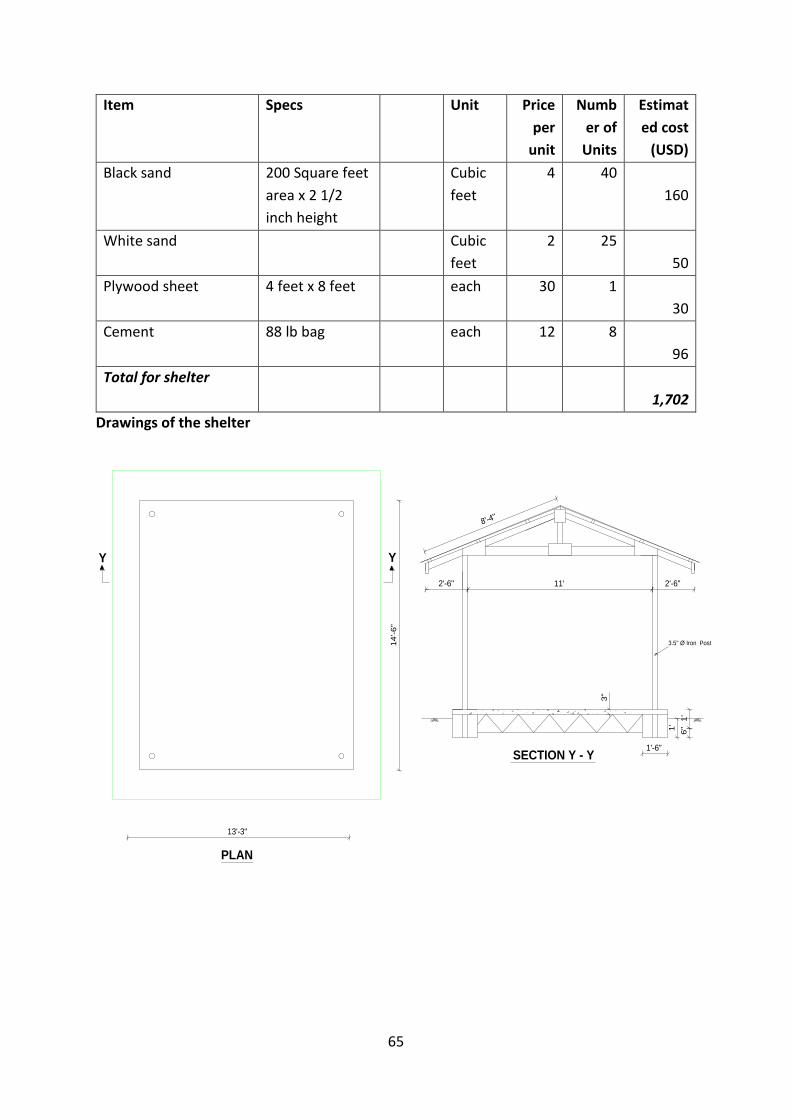
(USD)
Black sand 200 Square feet
area x 2 1/2
inch height
Cubic
feet
4 40
160
White sand Cubic
feet
2 25
50
Plywood sheet 4 feet x 8 feet each 30 1
30
Cement 88 lb bag each 12 8
96
Total for shelter
1,702
Drawings of the shelter
11' 2'-6"2'-6"
8'-4"
3.5" Ø Iron Post
1'
6"
1'-6"
1'
14
'-6"
13'-3"
3"
YY
PLAN
SECTION Y - Y
66
16'
DETAIL OF A TRUSS
12'-3"
END ELEVATION
5 Trusses at 3'-3"
intervals
1'-6"
1'-6"
DETAIL OF COLUMN
SECTION Y - Y
1'
6"
1'-6"
1'
Y Y
SECTIONAL ELEVATION
1:3:6(40mm) concrete floor
3"
3.5" Ø Iron Post
2" x 6" Timber
2" x 4" Timber
11'-7"
8'-4"
11’
67
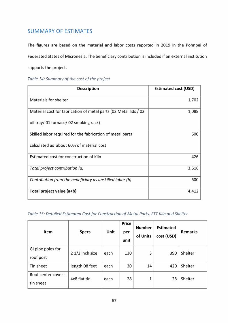
SUMMARY OF ESTIMATES The figures are based on the material and labor costs reported in 2019 in the Pohnpei of
Federated States of Micronesia. The beneficiary contribution is included if an external institution
supports the project.
Table 14: Summary of the cost of the project
Description Estimated cost (USD)
Materials for shelter 1,702
Material cost for fabrication of metal parts (02 Metal lids / 02
oil tray/ 01 furnace/ 02 smoking rack)
1,088
Skilled labor required for the fabrication of metal parts
calculated as about 60% of material cost
600
Estimated cost for construction of Kiln 426
Total project contribution (a) 3,616
Contribution from the beneficiary as unskilled labor (b) 600
Total project value (a+b) 4,412
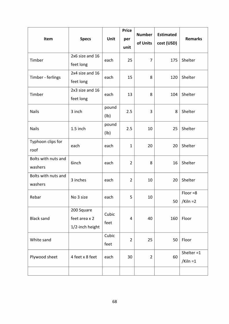
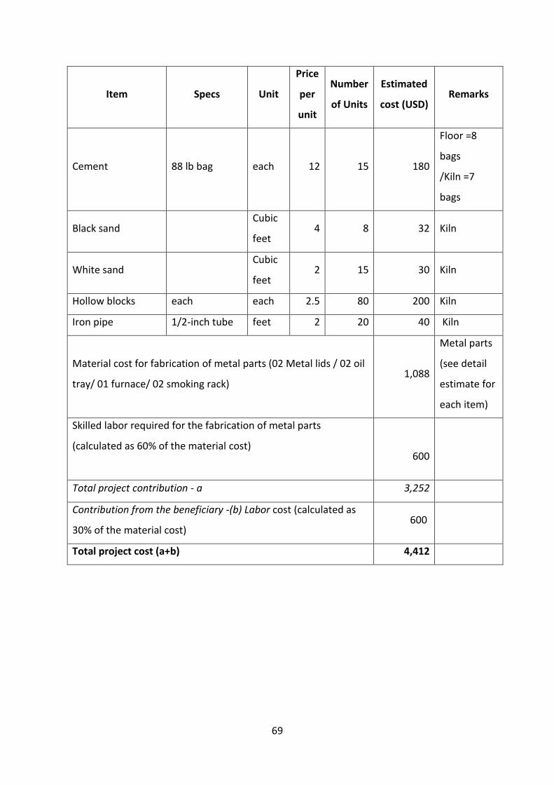
Table 15: Detailed Estimated Cost for Construction of Metal Parts, FTT Kiln and Shelter
Item Specs Unit
Price
per
unit
Number
of Units
Estimated
cost (USD) Remarks
GI pipe poles for
roof post 2 1/2 inch size each 130 3 390 Shelter
Tin sheet length 08 feet each 30 14 420 Shelter
Roof center cover -
tin sheet 4x8 flat tin each 28 1 28 Shelter
68
Item Specs Unit
Price
per
unit
Number
of Units
Estimated
cost (USD) Remarks
Timber 2x6 size and 16
feet long each 25 7 175 Shelter
Timber - ferlings 2x4 size and 16
feet long each 15 8 120 Shelter
Timber 2x3 size and 16
feet long each 13 8 104 Shelter
Nails 3 inch pound
(lb) 2.5 3 8 Shelter
Nails 1.5 inch pound
(lb) 2.5 10 25 Shelter
Typhoon clips for
roof each each 1 20 20 Shelter
Bolts with nuts and
washers 6inch each 2 8 16 Shelter
Bolts with nuts and
washers 3 inches each 2 10 20 Shelter
Rebar No 3 size each 5 10
50
Floor =8
/Kiln =2
Black sand
200 Square
feet area x 2
1/2-inch height
Cubic
feet 4 40 160 Floor
White sand Cubic
feet 2 25 50 Floor
Plywood sheet 4 feet x 8 feet each 30 2 60 Shelter =1
/Kiln =1
69
Item Specs Unit
Price
per
unit
Number
of Units
Estimated
cost (USD) Remarks
Cement 88 lb bag each 12 15 180
Floor =8
bags
/Kiln =7
bags
Black sand Cubic
feet 4 8 32 Kiln
White sand Cubic
feet 2 15 30 Kiln
Hollow blocks each each 2.5 80 200 Kiln
Iron pipe 1/2-inch tube feet 2 20 40 Kiln
Material cost for fabrication of metal parts (02 Metal lids / 02 oil
tray/ 01 furnace/ 02 smoking rack) 1,088
Metal parts
(see detail
estimate for
each item)
Skilled labor required for the fabrication of metal parts
(calculated as 60% of the material cost)
600
Total project contribution - a 3,252
Contribution from the beneficiary -(b) Labor cost (calculated as
30% of the material cost) 600
Total project cost (a+b) 4,412

70
REFERENCES FAO. 2019. The FAO thiaroye processing technique. How to construct it and assemble its components.
Rome, FAO. 4 pp. (also available at: http://www.fao.org/3/CA2559EN/ca2559en.pdf)
Mindjimba, K., Rosenthal, I., Diei-Ouadi, Y., Bomfeh, K. & Randrianantoandro, A. 2019. FAO Thiaroye
processing technique: towards adopting improved fish smoking systems in the context of benefits, trade-
offs and policy implications from selected developing countries. FAO Fisheries and Aquaculture Paper no.
634, 2019. Rome, FAO. 160 pp. (also available at www.researchgate.net/publication/346280763_FAO)
Ndiaye, O., Sodoke Komivi, B. & DieiOuadi, Y. 2014. Guide for developing and using the FAO Thiaroye
processing technique. Rome, FAO. 67 pp. (also available at: http://www.fao.org/3/a-i4174e.pdf)

71
FAO Subregional Office for the Pacific Islands, Tuanaimato, SIDs Road [email protected]
Food and Agriculture Organization of the United Nations
Apia, Samoa


![Powermate® Front Tine Rotary Tiller Operator’s Manual for P ...powermateoutdoor.com/pdfs/OM_DeluxeFrontTineTiller_P-FTT...MODEL No. P-FTT-160MD-[E] P-FTT-160MD If you have a question](https://img.pdfslide.us/doc/110x75/60aac877cfc02311cd72806a/powermate-front-tine-rotary-tiller-operatoras-manual-for-p-model-no.jpg)