Embed Size (px)
Citation preview
MODELING SECOND-ORDER VOLUMETRIC FEATURES
Robert B. Fisher
Department of Artificial IntelligenceEdinburgh University
ABSTRACT
Model creation using SMS's volumetricprimitives revealed that many models lacked thehighly salient visual details representable usingthe surface and space curve primitives, althoughthe first-order mass distribution of the featureswas well characterized. This paper introduceseight second-order volumetric features that adddetail to models, as might be required in a recog-nition scheme that used conceptual scale.
1. INTRODUCTION
SMS (Suggestive Modeling System) [Fisher1985] is a modeling system designed forrepresenting the salient visual features of objects,as needed by a recognition system that primarilyreceives three-dimensional image evidence (i.e.from a 2 1/2D sketch [Marr 1982]). SMSrepresents both structural and viewpoint depen-dent features and relationships. The primitivestructural features include points, space curves,surf ace patches and volumes. The intent of hav-ing the three classes of primitive features is toallow alternative recognition pathways, based onalternative evidence types.
The current volumetric primitives are theSTICK, the PLATE and the BLOB, which aredesigned for representing 1, 2 and 3 dimensionsof extension. That is. a STICK representselongated features (perhaps straight or slightlycurved). It will have some thickness, but this isgenerally minor compared to its length. ThePLATE represents flattish structures, again possi-bly having a slight curvature and thickness. TheBLOB represents more compact structures, havingsimilar dimensions.
AcknowledgementsThis work was performed under Alvey GrantGR/D/1740.3. This paper benefited greatly fromdiscussions with J. Aylett and M. Orr.
Larger structured assemblies are formedfrom these primitives using placements via refer-ence frame transformations.
While making volumetric representations ofsome test objects, it appeared that these represen-tations were impoverished compared to the sur-face patch and space curve representations. Thevolumetric features represented the first-ordermass distribution of the features well, which wastheir purpose, but glossed over many of the obvi-ous second-order, highly visual details. Themajor deficiencies were not having primitives forsmall intruding (or negative) features, like holes,and small extruding (or positive) features, suchas bumps.
The existing SMS volumetric primitives weresuitable for producing drawings containing smallextrusions, for example, by using small BLOBsoverlapping with the main volume. The problemis, however, representing the visual aspect of thefeature for recognition purposes, rather than fordrawing, and what is seen is a hemisphericalextrusion, rather than half of a BLOB. Hence,another representation should be considered. Afurther problem is that the shapes of the extru-sions do not correspond closely with those of thefirst-order primitives.
Jared [Jared] has recently been developingwork by Kyprianou [Kyprianou 1980] on shaperecognition. This work attempts to deduce themore global structure of a surface feature from alocal boundary (surface, edge and vertex)description, such as the existence of a protrusionfrom a set of connected planes. Here, featureswere classified as protrusions or depressions,which were further refined to slots, holes andpockets. While the deduction method (shapegrammars) is not of interest here, his proposedclassifications are a subset of those in this paper.Further, the work demonstrated the importanceof these second-order features (although heretheir role is related to part function andmanufacturing method).
79

The extensions to SMS given here bear somerelationship to the set-theoretic or constructivesolid geometry [Requicha 1977] approach. How-ever, here, the intent is to represent onlyvolumetric features that can be directly andeasily identified from 2 1/2D data. Further, themodel primitives are expected to closelycorrespond with the data primitives. This seemsto allow only disjunctive union and simple rela-tive complement operations. Generally. CSGprimitives and methods allow full boolean setoperations, leading to model features that neednot exist in the final object. Also, featuredescriptions are not canonical, leading to recogni-tion problems. A further problem is identifyingwhich CSG primitive owns a given final modelfeature (which is needed for verifying a model).
The general CSG object modeling approach isnot suitable for modeling objects for visual recog-nition, because the information about the visibleobject features are only implicit in the model.That is. one cannot easily tell what model featurea given image feature corresponds with, nor theextent of a surface feature.
This paper describes a set of small positive(extruding; and negative (intruding) volumetricfeatures, and provides a taxonomy for them, aswell as a defining syntax for use with the SMSmodeler. It also considers how to represent suchfeatures (the problem being how to remove themass associated with negative features).
In the conclusion we discuss how Marr's[Marr 1982] and Brady's [Brady 1983] criteria forevaluating representation systems apply to thenew features.
2 Positive Second-Order Volumetric FeaturesThese are small extrusions modifying a
major volumetric feature that do not merit afirst-order feature description. An example is acircular ridge lying around a STICK volume.
The second-order volumetric features can beclassified according to their having one. two orthree primary directions of extension.
The first one dimensional positive feature iscalled a SPIKE, which is a feature that sticks outfrom a volume and possibly bends (figure 1). Itis defined primarily by its length and bend curva-ture. The SMS model syntax is extended for thisfeature to include:
crois-radius
length = arc length of axisfrom A to 8 .
X i Y lie in planeof axis.Tperp
Origin at midpoint of spike.
Figure 1: Definition of SPIKE Feature
<Ieature_descr> ::-(SPIKE <name>
LENGTH <value>CROSS_RADIUS <value>BEND_RADIUS <value>
The CROSS_RADIUS property defines a nominalwidth of the SPIKE (but is intended to be small,and is required to be less than 1/2 the LENGTH;otherwise it should be called a BUMP). If theBEND_RADIUS is 0. then the SPIKE is straight.The <name> fields accept a character string nam-ing the feature. The <value> fields accept stan-dard arithmetic expressions in constants, vari-ables, binary arithmetic operators and someunary operators (e.g. cosine).
The second one dimensional positive featureis the RIDGE, which is a feature that lies on thesurface of a volume (figure 2). It is again definedprimarily by its length and bend curvature. Thesyntax for this feature is:
80

RIDGE l e n g t h : art length of Axis.
T t T lie in plane of Axis
Origin at midpoint of ridge.
Length = arc length of axis.
X 4 Y lie in planeof axs.
Origin at midpoint of base of fin
Figure 2: Definition of RIDGE Feature
<eature_descr> ::-(RIDGE <hame>
LENGTH <value>CROSS_RADIUS <Value>BEND_RADIUS <Value>
Figure 3: Definition of FIN Feature
and is required to be less than 1/2 the LENGTH).If the BEND_RADIUS is 0. then the FIN isstraight.
The CROSS_RADIUS property defines a nominalwidth and height of the RIDGE (but is intendedto be small, and is required to be less than 1/2the LENGTH). If the BEND_RADIUS is 0. thenthe RIDGE is straight.
The two dimensional positive feature is theFIN. which represents something like a RIDGE,but extends substantially out of the object (figure3). It is defined primarily by its length, heightand bend curvature. The syntax is:
<feature_descr> ::-(FIN <hame>
LENGTH <Value>CROSS_RADIUS <value>BEND_RADIUS <Value>HEIGHT <Value>
The CROSS_RADIUS property defines a nominalwidth of the FIN (but is intended to be small.
Figure 4: Definition of BUMP Feature
81

The three dimensional positive feature is theBUMP, representing a small hemi-ellipsoidalextrusion from a volume (figure 4). It is definedby its three radii of curvature, given as height.major_radius and minor_radius. The syntax is:
^eature_descr> ::-(BUMP <hame>
HEIGHT <value>MAJORJtADIUS <value>MINORJRADIUS <value>
3 Negative Second-Order Volumetric Features
These are small intrusions modifying amajor volumetric feature. They differ from thepositive features in that they cannot be approxi-mated by SMS's current volumetric primitives.They sculpt out portions of volumetric primi-tives, rather than add minor extensions. Anexample is a circular groove lying around aSTICK volume.
The second-order volumetric features can beclassified according to their having one, two orthree primary directions of extension.
The first one dimensional negative feature iscalled a HOLE, which sticks into a volume andpossibly bends (figure 5). This is the analogue of
the SPIKE positive feature. Here, the HOLE isrequired to pass completely through the volume,otherwise it would be called a DENT (below).The justification for the distinction is that typical3D image evidence is unlikely to distinguishbetween shallow and deep DENTs, whereas aHOLE can at least occasionally be identified byseeing completely through the object (as in thehandle on a teacup). As a HOLE through a thicksolid is indistinguishable from a deep DENT frommany viewpoints, there is clearly some ambiguityof interpretation, but this is no different to decid-ing between a PLATE and a BLOB when lookingalong the normal to the PLATE.
The HOLE is defined primarily by its lengthand bend curvature. The syntax is:
<feature_descr> ::->(HOLE <hame>
LENGTH <value>CROSSJtADIUS <value>BEND_RADIUS <value>
The CROSS_RADIUS property defines a nominalwidth of the HOLE (but is intended to be small,and is required to be less than 1/2 the LENGTH).If the BEND_RADIUS is 0. then the HOLE isstraight.
GROOVE
HOLE2«<ross-radius
Leng th ; arc iength of Axisfrom A to B.
ITfc Y lie in plane of Axis
Origin at midpoint of groove.
Length=arc length of Axisfrom A to B
X i Y lie in plane of Axis,
Z perp.
Origin at midpoint of hole.
Figure 5: Definition of HOLE Feature Figure 6: Definition of GROOVE Feature
82

The second one dimensional negative featureis the GROOVE, which is a feature that lies onthe surface of a volume (figure 6). It is the nega-tive analogue of the RIDGE and is primarilydefined by its length and bend curvature. Thesyntax is:
<Ieature_descr> :>(GROOVE <hame>
LENGTH <value>CROSS.RADIUS <value>BEND_RADIUS <value>
The CROSS.RADIUS property defines a nominalwidth and height of the RIDGE (but is intendedto be small, and is required to be less than 1/2the LENGTH). If the BEND_RADIUS is 0. thenthe RIDGE is straight.
The two dimensional negative feature is theSLOT, which is intended to represent somethinglike a GROOVE, but which extends substantiallyinto the object (figure 7). It is the negative analo-gue of the FIN and is primarily defined by itslength, depth and bend curvature. The syntax is:
<"eature_descr> ::<-(SLOT Oiame>
LENGTH <Value>CROSS_RADIUS <value>BEND_RADIUS <value>DEPTH <value>
The CROSS_RADIUS property defines a nominalwidth of the SLOT (but is intended to be small,and is required to be less than 1/2 the LENGTH).If the BEND_RADIUS is 0. then the SLOT isstraight.
The three dimensional negative feature is theDENT, which represents a small hemi-ellipsoidalintrusion into a volume (figure 8). It is the nega-tive analogue of the BUMP and is defined by itsthree radii of curvature, given as depth.major_radius and minor_radius. The syntax is:
<eature_descr> ::-(DENT <name>
DEPTH <value>MAJORJtADIUS <value>MINOR_RADIUS <value>
)
SLOT
deoth
Length = arc length of Axis.
X & Y lie inplane of Axis.
DENT
Origin at mtqxwit of topof slot.
Figure 7: Definition of SLOT Feature Figure 8: Definition of DENT Feature
83

4 ExamplesFigure 9 shows examples of an object con-
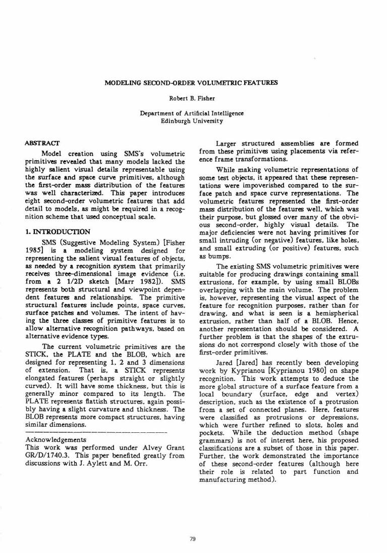
taining SPIKE. RIDGE. FIN and BUMP features.Figure 10 shows examples of an object containingHOLE. GROOVE. SLOT and DENT features.Since the first-order feature in both cases is onlya STICK (e.g. the largish cylindrical shape), thesecond-order features clearly add important dis-tinguishing detail. Figures 11 and 12 showvolumetric models of the widget with andwithout the second order features.
5 DiscussionMarr [Marr 1982] proposed 5 criteria for
evaluating a visual representation system: accessi-bility, scope, uniqueress, stability and sensitivity.While no developed processes derive volumetricrepresentations from the 2 1/2D data yet, webelieve that rough volumetric approximations areacquirable. The positive extensions are roughlyof the same class, only smaller, so should also beaccessible. The negative extensions are new, butseem to be simple, requiring answering only sim-ple questions. For example:
Figure 9: Example Using Positive Features
Figure 10: Example Using Negative Features
/* positive features */if it is an extrusion
then if it is shallowthen if it is elongated
then it is a RIDGEelse it is a BUMP
else if it is elongatedthen it is a FINelse it is a SPIKE
/* negative features */if it is an intrusion
then if it is shallowthen if it is elongated
then it is a GROOVEelse it is a DENT
else if it is elongatedthen it is a SLOTelse it is a HOLE
Hence, the accessibility criterion should besatisfied. The modeling extensions increase theclass of shapes representable, hence enhance thescope criterion. Since the above tests are mutu-ally exclusive, and since the features are usedlargely for disjunctive unions and simple comple-mentation, there is likely to be only a uniquerepresentation for any data feature, or at mostonly a few related alternatives. For example, if
84
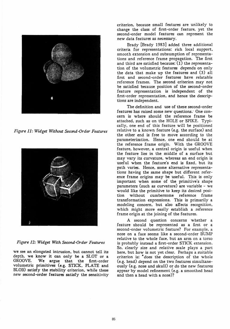
Figure 11: Widget Without Second-Order Features
Figure 12: Widget With Second-Order Features
we see an elongated intrusion, but cannot tell itsdepth, we know it can only be a SLOT or aGROOVE. We argue that the first-ordervolumetric primitives (e.g. STICK. PLATE andBLOB) satisfy the stability criterion, while thesenew second-order features satisfy the sensitivity
criterion, because small features are unlikely tochange the class of first-order feature, yet thesecond-order model features can represent thenew data features as necessary.
Brady [Brady 1983] added three additionalcriteria for representations: rich local support,smooth extension and subsumption of representa-tions and reference frame propagation. The firstand third are satisfied because: (l) the representa-tion of the volumetric features depends on onlythe data that make up the features and (3) allfirst and second-order features have relatablereference frames. The second criterion may notbe satisfied because position of the second-orderfeature representation is independent of thefirst-order representation, and hence the descrip-tions are independent.
The definition and use of these second-orderfeatures has raised some new questions." One con-cern is where should the reference frame beattached, such as on the HOLE or SPIKE. Typi-cally, one end of this feature will be positionedrelative to a known feature (e.g. the surface) andthe other end is free to move according to theparameterization. Hence, one end should be atthe reference frame origin. With the GROOVEfeature, however, a central origin is useful whenthe feature lies in the middle of a surface butmay vary its curvature, whereas an end origin isuseful when the feature's end is fixed, but itspath varies. Hence, some alternative representa-tions having the same shape but different refer-ence frame origins may be useful. This is onlyimportant when some of the primitive's shapeparameters (such as curvature) are variable - wewould like the primitive to keep its desired posi-tion without cumbersome reference frametransformation expressions. This is primarily amodeling concern, but also affects recognition,which might more easily establish a referenceframe origin at the joining of the features.
A second question concerns whether afeature should be represented as a first or asecond-order volumetric feature? For example, anose on a face seems like a second-order BUMPrelative to the whole face, but an arm on a torsois probably instead a first-order STICK extension.So. clearly size and relative scale plays a parthere, but how is not yet clear. Perhaps a suitablecriterion is: "does the description of the whole(e.g. head) depend on the two features simultane-ously (e.g. nose and skull) or do the new featuresappear by model refinement (e.g. a smoothed headand then a head with a nose)?
85

Adding the positive features pose no majorproblems to the existing SMS modeling scheme.However, the negative features differ in that theyremove material from existing positive features(i.e. the portion of a positive feature lying insidea negative feature does not exist). Following this,a BUMP lying on the inside surface of a HOLEcannot be represented. This suggests that a fullconstructive solid geometry (CSG) approach (e.g.[Requicha 1977]) might be adopted to overcomethese problems.
The role of these new features in recognitionis still hard to assess because there are not yetdata analysis processes producing volumetricdescriptions, let alone processes producing scale-based descriptions. We hypothesize that thefirst-order features will be useful for broad classidentifications and rough location, and thesecond-order features will refine subclassidentifications and locations (much as in ACRO-NYM [Brooks 1981]). Further, the feature classesare both distinct and symbolic, promoting rela-tional matching algorithms.
These comments converge on the real pointof the extensions - the second-order primitivesintroduce new capabilities needed for havingalternative conceptual scale object representa-tions. SMS currently links models by ELA-BORATION and SIMPLIFICATION, where linkedmodels may have radically different structures(as in replacing a hand with 5 separate fingers bya BLOB). These second-order features will nowallow object representations with first the basicshape and then (incrementally) finer details.
Some easy extensions could be made to thesecond-order primitives to allow features thattwist, undulate and vary shape (perhaps like gen-eralized cylinders). It is likely that other primi-tive shapes exist, too. While more effort could bespent on improving the primitives, leading tomore accurate object models, we believe moreeffort should be spent on using the models forrecognition (which we are pursuing).
The SMS models are intended to capture the"feel" of the objects, that is, their suggestive andvisually salient aspects, rather than their metri-cally accurate character. Hence, the descriptionsconcentrate on "humanly" nameable volumetricfeatures, and the second-order volumetricfeatures defined here add new descriptions of thistype to those originally used in SMS.
6
7
REFERENCESBrady. M., "Criteria for Representationsof Shape", in Beck. Hope and Rosenfeld(eds). Human and Machine Vision,Academic Press. 1983.Brooks, R.A., "Symbolic reasoningamong 3-D models and 2-D images",Artif. Intel., 17, pp285-348, 1981.Fisher. R.B.. "SMS: a suggestive model-ing system for object recognition", Im-age and Vision Comp.. 5. pp98-104.1987.Jared, G.E.M., "Shape Features inGeometrical Modeling", Unpublished re-port(?), Dept. of Engineering, Univ. ofCambridge, date?.Kyprianou. L.K.. "Shape Classificationin Computer-Aided Design", PhD thesis.Univ. of Cambridge Computer Lab,1980.[Marr 1982] Marr, D., Vision, W. H.Freeman, San Francisco, 1982.[Requicha 1977] Requicha. A. A. G..Voelcker. H. B.. "Constructive SolidGeometry", Univ. of Rochester. Produc-tion Automation Project, memo TM-25.1977.
86