Embed Size (px)
Citation preview
1
The experiment of Self-charging Inverter driven by
The 3rd Positive EMF
(This report is based on Author's poster presentation at MANA-RSC symposium in Tsukuba
on 15,16 October, 2015.)
Osamu Ide
Foundation for the Advancement of Environmental Energy (FAEE)
Clean Energy Research Laboratory,
3-4-21-601 Mita, Minato-ku, Tokyo, 108-0073, Japan,
Email: [email protected] Email: [email protected]
Abstract EMF means electro-motive force found by Michael Faraday of Royal institution of Great Britain in
1831. He found two types of EMF. One is mono-polar induction which generates DC current. Another
is electro-magnetic induction which is familiar to generate AC electricity by almost all the power plant
in the world. The 3rd positive EMF was found by the author in 1980. It is different and independent
from Faraday’s EMF. It is induced if the time changing of the magnetic flux is so high. For an example
just like a switching instant of electrical device containing inductance. The most important feature is
the direction of EMF. It is opposite to the Faraday’s EMF. As Faraday’s EMF is called back EMF, so
it might be called positive EMF. It accelerates the input current to the device with inductance. Although
it is generated in a short moment of electrical switching, if you could catch the positive EMF you
would get an extra electrical energy. Author had succeeded to make a prototype of inverter applying
the positive EMF. The power efficiency of it easily exceeds 100%. The 3rd positive EMF is not a
natural resource but physical electromagnetic power probably from fluctuation of space time. Author
has finally succeeded to make an experiment of self-charging system without input energy. The system
is composed of battery, inverter and controller. The inverter is operated by the battery and the output
of inverter recharges the battery. Some load resistance is connected to the battery during operation.
After the operation, the voltage of the battery is equivalent or higher than the initial voltage. This
experiment proves the possibility of making perfect clean energy generator.
Keyword: EMF, Faraday, Positive EMF, Inverter, Self-charging, Battery
2
1 Introduction
In 1973, author started to research completely new and clean energy when author had read a book
and paper written by Prof. Shin-ichi Seike in Japan. Then author had received an information of EMA
motor. It was invented and patented by Edwin・Gray in LA,1970. EMA motor had unique configuration
and quality. They said it runs itself. It runs by high voltage discharging of the capacitors so that it has
spark gaps. Discharging current of the capacitors flows in the motor coils and makes it run.
In 1976, author started to reproduce EMA motor to confirm it' s strange characteristic. Author
made three different prototype of the motor called Ether-engine. As a result, it was not able to run
itself.
But in 1980, author has found strange phenomenon in 2nd Ether-engine. It is the 3rd positive EMF.
When Ether-engine runs, the static charge of the capacitors which is not consumed for running Ethel-
engine was recycled to the capacitors and used for next discharge. This operation is on the electrical
theory. Author precisely measured the initial voltage of the capacitor before discharge and the recycled
voltage after discharge and considered the relation between them. Author found the recycled voltage
of when the motor is running is a little larger than that of motor stops within some limited condition.
It looks strange to physical theory. It depends on the magnetic configuration and the rotation speed of
motor. (1)(2)
Author calculated the recharged voltage by Faraday's law. The result of the calculation shows that
voltage increasing of capacitors in the motor never occurs, and it should be quite natural on the theory
of electro-magnetism.
Then author had an idea to deduce the hypothesis of the 3rd positive EMF which is different and
independent from Faraday's electro-magnetic induction induced in the motor coils to explain strange
phenomenon of increasing charged voltage of the capacitors. Direction of the 3rd positive EMF must
be opposite to Faraday's back EMF as a reaction. So discharging current in the motor coils are
accelerated by the 3rd positive EMF. It might be a kind of reaction but the direction is opposite. So the
recharged voltage of capacitors after discharging is increased. This hypothesis looks to explain over
charging phenomenon of the capacitors in 2nd Ether-engine. (1)
Author has tried the measuring and the calculation more precisely and found the 3rd positive
EMF has a physical rule. If it has some physical rule, it is not noise but must be really new electro-
magnetic induction.
Inductance of the motor coil is depending on the position of stator and rotor. When the motor
runs the inductance of motor coils are changed by the position between stator and rotor. The 3rd EMF
seems to be induced when the time changing of the inductance is very high and the function of second
order time differential of inductance. (2)(10)(11)
In 1988, Author made 3rd Ether-Engine. Then the efficiency of it calculated by the total output of
3
including mechanical, electrical and magnetic loss of Ether-engine reaches 110% ( maximum: 113% ).
But it is not enough to be possible to make self-sustaining generator as the total loss of Ether-
engine is very large.
In 2000, Author turned the research to inverter applying the 3rd positive EMF. The inner loss of
inverter is smaller compared with motor as it has no mechanical loss.
In 2010, Author had succeed to make the inverter of over 100% efficiency and found The 3rd
positive EMF is also generated by high speed changing of input current to the coil(inductance).
(3)(4)(7)
Author calls the inverter Degoichi. This name is from famous and popular SL in Japan. Then the 3rd
term of EMF function (1) [equation 13 in (2)] author had deduced was totally proved. Because it is
proved that it generates by high speed time changing of not only inductance (L) but also current (I). It
means high speed changing of the magnetic flux (Ф=LI).
EMF = 𝐾0𝛷 − 𝐾1
𝑑𝛷
𝑑𝑡+ 𝐾2
𝑑2𝛷
𝑑𝑡2− 𝐾3
𝑑3𝛷
𝑑𝑡3+・・・+ ( −1 )𝑛𝐾𝑛
𝑑𝑛𝛷
𝑑𝑡𝑛+・・・( 1 )
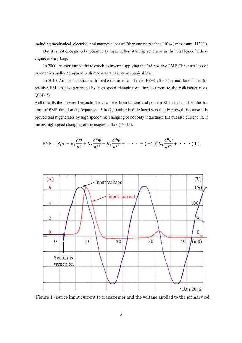
Figure 1 : Surge input current to transformer and the voltage applied to the primary coil
4
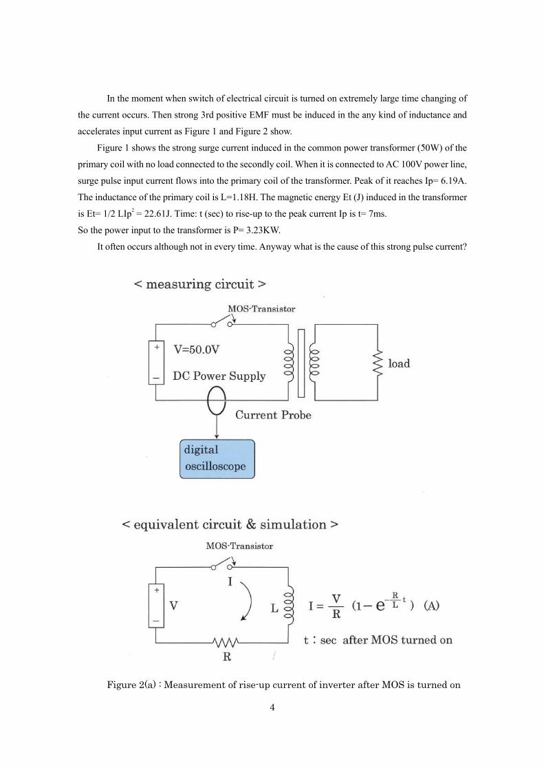
In the moment when switch of electrical circuit is turned on extremely large time changing of
the current occurs. Then strong 3rd positive EMF must be induced in the any kind of inductance and
accelerates input current as Figure 1 and Figure 2 show.
Figure 1 shows the strong surge current induced in the common power transformer (50W) of the
primary coil with no load connected to the secondly coil. When it is connected to AC 100V power line,
surge pulse input current flows into the primary coil of the transformer. Peak of it reaches Ip= 6.19A.
The inductance of the primary coil is L=1.18H. The magnetic energy Et (J) induced in the transformer
is Et= 1/2 LIp2 = 22.61J. Time: t (sec) to rise-up to the peak current Ip is t= 7ms.
So the power input to the transformer is P= 3.23KW.
It often occurs although not in every time. Anyway what is the cause of this strong pulse current?
Figure 2(a) : Measurement of rise-up current of inverter after MOS is turned on
5
Figure 2(a) shows measuring and equivalent circuit of inverter to check rise-up current just after MOS-
transistor is turned on.
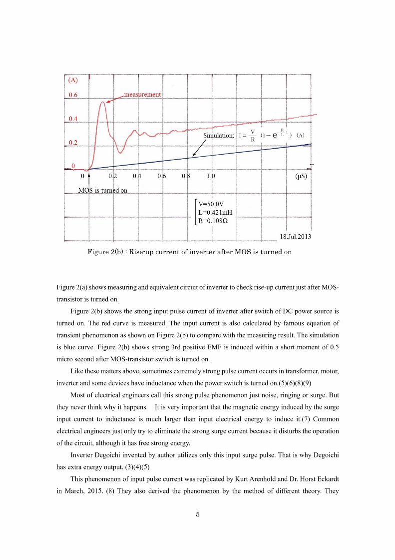
Figure 2(b) shows the strong input pulse current of inverter after switch of DC power source is
turned on. The red curve is measured. The input current is also calculated by famous equation of
transient phenomenon as shown on Figure 2(b) to compare with the measuring result. The simulation
is blue curve. Figure 2(b) shows strong 3rd positive EMF is induced within a short moment of 0.5
micro second after MOS-transistor switch is turned on.
Like these matters above, sometimes extremely strong pulse current occurs in transformer, motor,
inverter and some devices have inductance when the power switch is turned on.(5)(6)(8)(9)
Most of electrical engineers call this strong pulse phenomenon just noise, ringing or surge. But
they never think why it happens. It is very important that the magnetic energy induced by the surge
input current to inductance is much larger than input electrical energy to induce it.(7) Common
electrical engineers just only try to eliminate the strong surge current because it disturbs the operation
of the circuit, although it has free strong energy.
Inverter Degoichi invented by author utilizes only this input surge pulse. That is why Degoichi
has extra energy output. (3)(4)(5)
This phenomenon of input pulse current was replicated by Kurt Arenhold and Dr. Horst Eckardt
in March, 2015. (8) They also derived the phenomenon by the method of different theory. They
Figure 2(b) : Rise-up current of inverter after MOS is turned on
6
calculated the phenomenon by ECE theory of Dr. Myron Evans and proved it is from fluctuation of
space time. The result shows amazing coincidence with measurement and simulation.
Since 2011, author tried to check the feature of Degoichi and found the efficiency was getting to
increase little by little. In 2014, it reached more than 600%. But the heat output of the load seemed to
be less than the expected value. Then Author found the value of the output current measured by
analogue meter, magnetic current probe and shunt resistance current probe are all getting extremely
large. And so then it looks Ohm's law is violated.
It seems the extra unknown current of no heat is accompanied with ordinary current. Sometimes
it is called "cold current". The paper of Dr. Douglas Lindstrom explained cold current by ECE theory.
(12)
This cold current could generate electro-magnetic force as same as ordinary current. Because it
could move the pointer of analogue current meter. Then, DC motor running test by the output current
from Degoichi was done to compare with the ordinary DC current from common DC power supply.
The result is so interesting that DC motor runs by the output current from Degoichi 1.1~1.2
times faster than common DC current of identical value from DC power supply. And also it runs
smoother than by common DC current. Although the reason is not clear but these series of experiments
show different kind of electrical current should be existing and flows out from Degoichi. Author would
reports on the motor running test in near future.
It might be seemed to be easy recycling the output power to battery and to make it self-sustaining
or self-exciting system if Degoichi had enough efficiency of beyond 100%. But it is so difficult that
the output current from Degoichi is not ordinary, might be different kind of cold current just described
above. It should be made the system of Degoichi, battery and the controller together. The battery must
be able to charge by the output of Degoichi.
In August, 2015, author had succeeded to make self-charging experiment. It was composed of
Degoichi inverter, batteries, special coils, capacitors and switches. It looks more complicated circuit
than expected by common electrical engineers.
And the result, if it is operated with no load connected to the battery, the voltage of the battery
increases after operation. If the battery has some load connected during operation the battery voltage
is equivalent or a little larger than the initial voltage. The result shows the battery is charged by the
output of Degoichi more than the discharging to operate Degoichi. The heat output power of the load
connected to the battery is around 0.85W.
The output power of this system is exactly new and clean source of energy, no need for natural
resources.
7
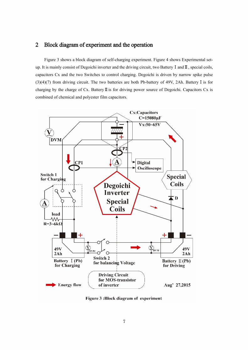
2 Block diagram of experiment and the operation
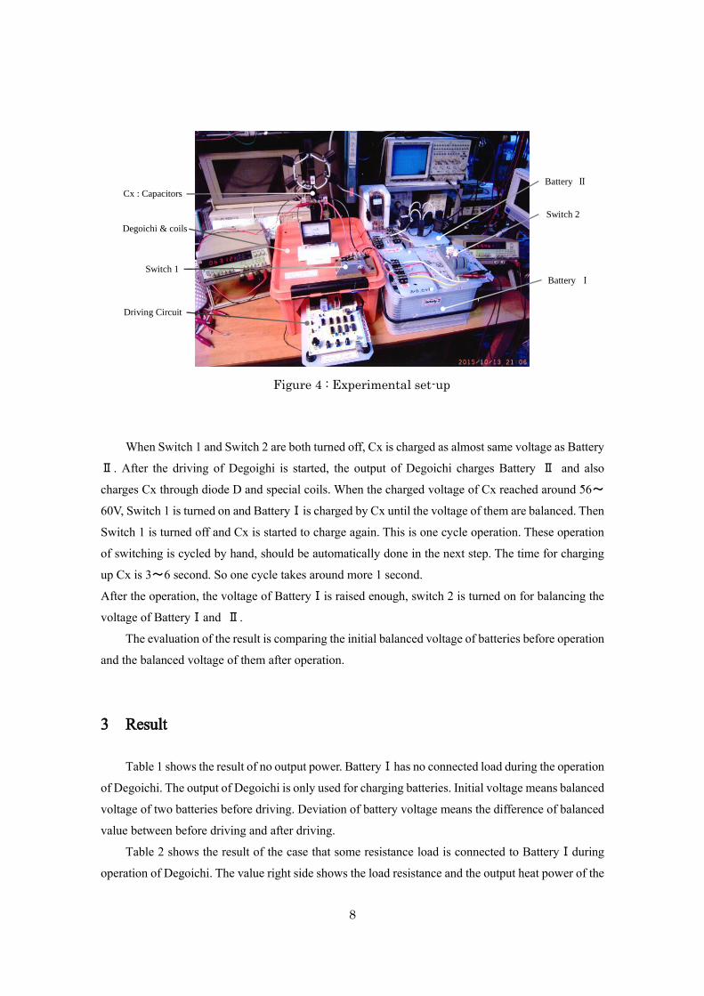
Figure 3 shows a block diagram of self-charging experiment. Figure 4 shows Experimental set-
up. It is mainly consist of Degoichi inverter and the driving circuit, two BatteryⅠandⅡ, special coils,
capacitors Cx and the two Switches to control charging. Degoichi is driven by narrow spike pulse
(3)(4)(7) from driving circuit. The two batteries are both Pb-battery of 49V, 2Ah. BatteryⅠis for
charging by the charge of Cx. BatteryⅡis for driving power source of Degoichi. Capacitors Cx is
combined of chemical and polyester film capacitors.
8
When Switch 1 and Switch 2 are both turned off, Cx is charged as almost same voltage as Battery
Ⅱ. After the driving of Degoighi is started, the output of Degoichi charges Battery Ⅱ and also
charges Cx through diode D and special coils. When the charged voltage of Cx reached around 56~
60V, Switch 1 is turned on and BatteryⅠis charged by Cx until the voltage of them are balanced. Then
Switch 1 is turned off and Cx is started to charge again. This is one cycle operation. These operation
of switching is cycled by hand, should be automatically done in the next step. The time for charging
up Cx is 3~6 second. So one cycle takes around more 1 second.
After the operation, the voltage of BatteryⅠis raised enough, switch 2 is turned on for balancing the
voltage of BatteryⅠand Ⅱ.
The evaluation of the result is comparing the initial balanced voltage of batteries before operation
and the balanced voltage of them after operation.
3 Result
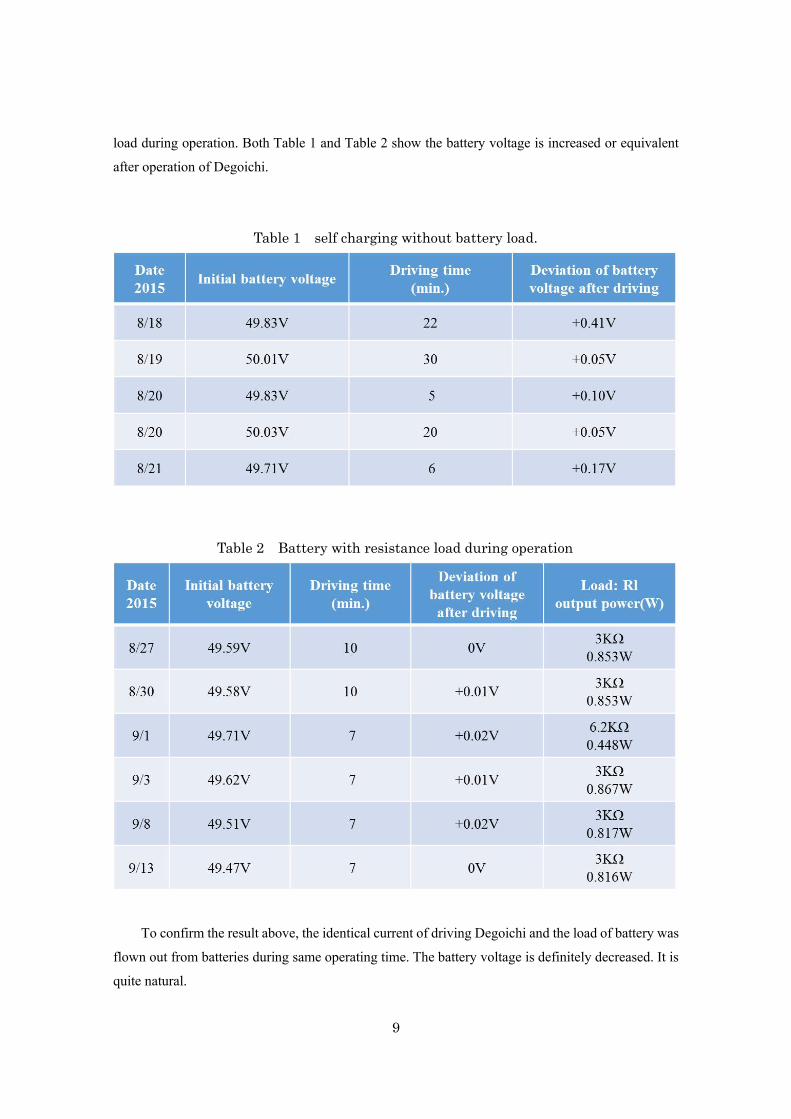
Table 1 shows the result of no output power. BatteryⅠhas no connected load during the operation
of Degoichi. The output of Degoichi is only used for charging batteries. Initial voltage means balanced
voltage of two batteries before driving. Deviation of battery voltage means the difference of balanced
value between before driving and after driving.
Table 2 shows the result of the case that some resistance load is connected to BatteryⅠduring
operation of Degoichi. The value right side shows the load resistance and the output heat power of the
Figure 4 : Experimental set-up
Cx : Capacitors
Degoichi & coils
Switch 1
Driving Circuit
Battery Ⅱ
Switch 2
Battery Ⅰ
9
load during operation. Both Table 1 and Table 2 show the battery voltage is increased or equivalent
after operation of Degoichi.
To confirm the result above, the identical current of driving Degoichi and the load of battery was
flown out from batteries during same operating time. The battery voltage is definitely decreased. It is
quite natural.
Table 1 self charging without battery load.
Table 2 Battery with resistance load during operation
10
4 Confirming test
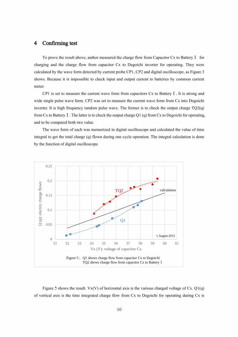
To prove the result above, author measured the charge flow from Capacitor Cx to BatteryⅠ for
charging and the charge flow from capacitor Cx to Degoichi inverter for operating. They were
calculated by the wave form detected by current probe CP1, CP2 and digital oscilloscope, as Figure 3
shows. Because it is impossible to check input and output current to batteries by common current
meter.
CP1 is set to measure the current wave form from capacitors Cx to BatteryⅠ. It is strong and
wide single pulse wave form. CP2 was set to measure the current wave form from Cx into Degoichi
inverter. It is high frequency random pulse wave. The former is to check the output charge TQ2(q)
from Cx to BatteryⅠ. The latter is to check the output charge Q1 (q) from Cx to Degoichi for operating,
and to be compared both two value.
The wave form of each was memorized in digital oscilloscope and calculated the value of time
integral to get the total charge (q) flown during one cycle operation. The integral calculation is done
by the function of digital oscilloscope.
Figure 5 shows the result. Vx(V) of horizontal axis is the various charged voltage of Cx. Q1(q)
of vertical axis is the time integrated charge flow from Cx to Degoichi for operating during Cx is
0
0.05
0.1
0.15
0.2
0.25
51 52 53 54 55 56 57 58 59 60 61
Q (
q):
ele
ctri
c ch
arge
flo
wn
Vx (V): voltage of capacitor Cx
Figure 5 : Q1 shows charge flow from capacitor Cx to Degoichi
TQ2 shows charge flow from capacitor Cx to BatteryⅠ
calculation
Q1
TQ2
1.Augast.2015
11
charged up to Vx(V). TQ2(q) of vertical axis is also the time integrated charge flow from Cx to Battery
Ⅰ for charging after Switch 1 is turned on until the voltage of BatteryⅠ and Cx are balanced.
The calculated value of TQ2 is shown for reference. It should be linear on electrical theory.
Figure 5 shows it has is exactly the difference between Q1 and TQ2. Then the result of this
measurement proves the result of Table 1 and 2. The charge flow from Cx to BatteryⅠ for charging
is larger than charge flow from Cx to operate Degoichi.
It is difficult to understand that the calculation curve is also less than TQ2. It means extra charge
is produced during the current flow from Cx to BatteryⅠ.
5 Questions unsolved and the model of self-exciting generator
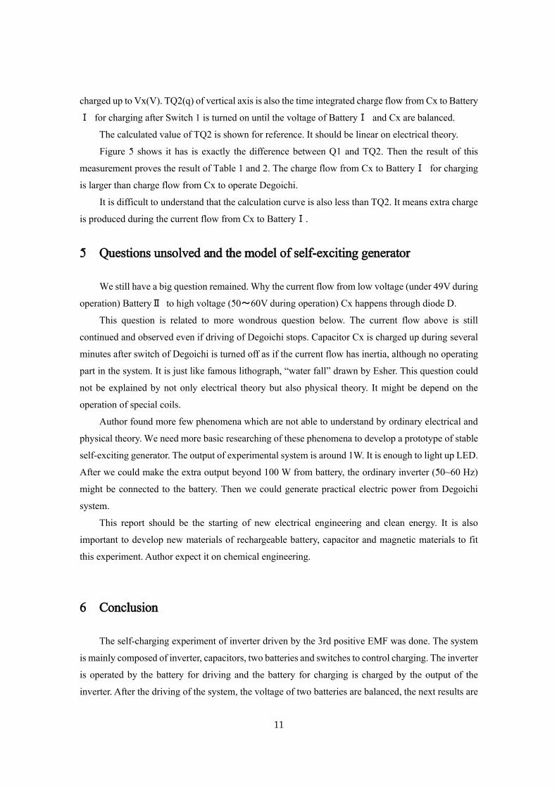
We still have a big question remained. Why the current flow from low voltage (under 49V during
operation) BatteryⅡ to high voltage (50~60V during operation) Cx happens through diode D.
This question is related to more wondrous question below. The current flow above is still
continued and observed even if driving of Degoichi stops. Capacitor Cx is charged up during several
minutes after switch of Degoichi is turned off as if the current flow has inertia, although no operating
part in the system. It is just like famous lithograph, “water fall” drawn by Esher. This question could
not be explained by not only electrical theory but also physical theory. It might be depend on the
operation of special coils.
Author found more few phenomena which are not able to understand by ordinary electrical and
physical theory. We need more basic researching of these phenomena to develop a prototype of stable
self-exciting generator. The output of experimental system is around 1W. It is enough to light up LED.
After we could make the extra output beyond 100 W from battery, the ordinary inverter (50~60 Hz)
might be connected to the battery. Then we could generate practical electric power from Degoichi
system.
This report should be the starting of new electrical engineering and clean energy. It is also
important to develop new materials of rechargeable battery, capacitor and magnetic materials to fit
this experiment. Author expect it on chemical engineering.
6 Conclusion
The self-charging experiment of inverter driven by the 3rd positive EMF was done. The system
is mainly composed of inverter, capacitors, two batteries and switches to control charging. The inverter
is operated by the battery for driving and the battery for charging is charged by the output of the
inverter. After the driving of the system, the voltage of two batteries are balanced, the next results are
12
obtained.
1.After 5~30 minutes driving with no load connected to the battery, battery voltage balanced after
operation is always larger than initial balanced voltage.
2.After 7~10 minutes driving with some load resistance connected to the battery, balanced battery
voltage is similar or a little larger than initial balanced voltage.
It might be possible to make self-exciting generator which is no pollution and clean, and needs
no natural resources.
7 Acknowledgements
Author especially appreciate Dr. Myron Evans, Dr. Horst Eckardt, Dr. Douglas Lindstrom and
Mr. Franklin D. Amador of AIAS for supporting and advice for my research.
Author received valuable advice from Dr. Takao Yamazaki and Mr. Takashi Maeza.
Author appreciate Mr. Takayuki Funabashi and Miss Honami Ichinose for drawing Figures of
this report.
Many thanks to Yuriko Ide for operating PC.
References
(1) Ide, O.,” Increased voltage phenomenon in a resonance circuit of unconventional magnetic
configuration”, J.Appl.Phys.,77(11), (1995),pp6015-6020.
(2) Ide, O., “ Possibility of existence of non-linear electromotive force (EMF)”, NASA/CP-2000-
21029, (July 2000), pp705-719.
(3) Ide, O., “ A Hyper-Efficient Inverter Driven by Positive EMF in Combination with Transient
Phenomenon “, SPESIF 2011, Physics Procedia, Vol.20, (2011), pp420-434.
(4) Ide, O., et al, “Anomalous Power Efficiency of a Transformer Driven by Tuned
Duty Cycle Pulses” made public at the Space Propulsion & Energy Sciences
International Forum-2012 (SPESIF) edited by T. Valone, Physics Procedia, Volume
38, 2012, pp 99-108.
(5) Ide, O., et al, “Anomalous rising of input current induced in the transformer of the inverter”
presented at 249th American Chemical Society National Meeting & Exposition at Denver in March 24,
2015, ENFL 350.
(6) Ide, O., et al, “Consideration of the cause of inverter noise called ringing” presented at 249th
13
American Chemical Society National Meeting & Exposition at Denver in March 24, 2015, ENFL 351.
(7) Ide, O., “Characteristics of DC power output from an inverter driven by sharp spike pulse”
presented at 249th American Chemical Society National Meeting & Exposition at Denver in March 24,
2015, ENFL 352.
(8)Kurt Arenhold, Horst Eckardt., “Experimental verification and theoretical explanation of the
Osamu Ide experiment”, June 23, 2015.
http://aias.us/documents/uft/UFT311_IdeExp.pdf
(9) Horst Eckardt, Douglas W. Lindstrom., “Circuit theory for unusual inductor behavior”, July 9,
2015
http://aias.us/documents/uft/CircuitTheory.pdf
(10) Franklin D. Amador, Horst Eckardt., “Simulation of a Parametric Resonance Circuit”. March 30,
2012. http://aias.us
(11)Horst Eckardt, B. Foltz., “Simulation of a Parametric Resonance Circuit, Part2” http://aias.us/
(12)Douglas W. Lindstrom., “On the Possible Existence of a Second Form of Electrical Current in the
ECE Equations of Electromagnetism”
http://www.aias.us/documents/numerical/ECE-2nd-Current.pdf