Embed Size (px)
Citation preview

The evolution of synchrotron radiation and the growth of its importance in
crystallography
John R Helliwell
The BCA Lonsdale Lecture and Teaching Plenary 2011
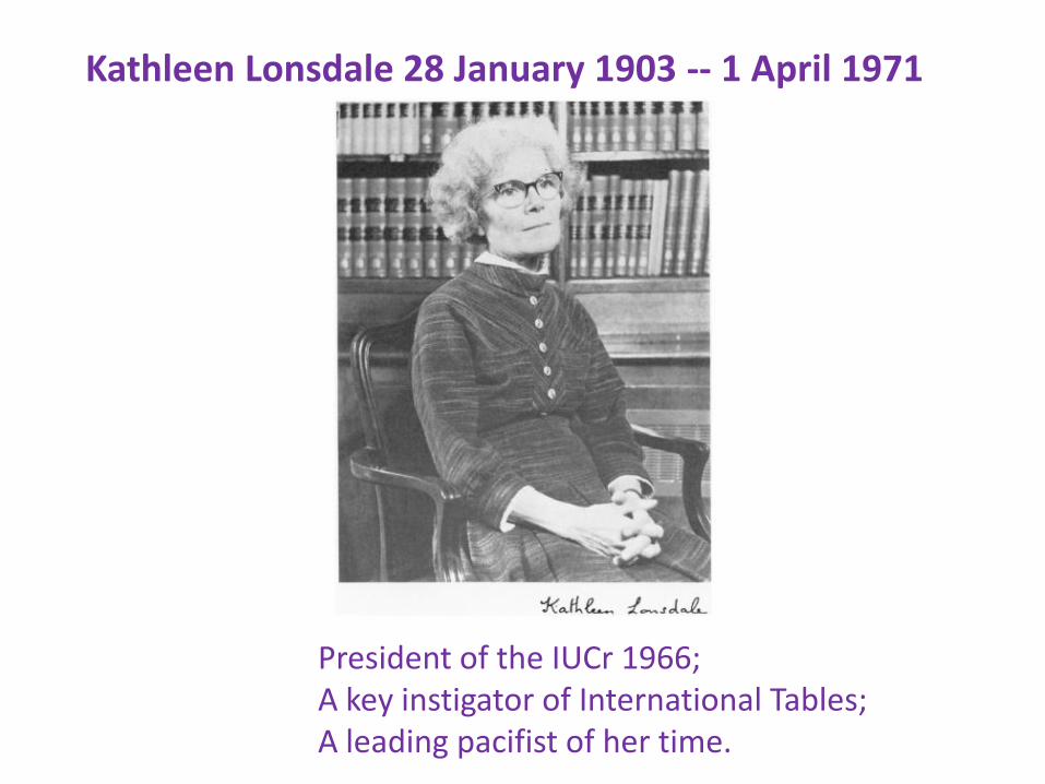
President of the IUCr 1966;A key instigator of International Tables;A leading pacifist of her time.
Kathleen Lonsdale 28 January 1903 -- 1 April 1971

1931 An X-ray analysis of the structure of hexachlorobenzene by the Fourier method

Synchrotron radiation
• Small focal spots, AND
• Collimated X-ray beams onto the crystal
• Tunable
• And for special applications:-
• White beam for time-resolved fast data
• Defined time structure eg picosecond bunches
• Also plane polarised

A vision for adoption of synchrotron radiation in crystallography (Daresbury Study Weekend 1979)
• In my talk 'Optimisation of anomalous scattering and structural studies of proteins using synchrotron radiation', Proc. of Daresbury Study Weekend, 26-28 January 1979 DL/SCI/R13. (1979) pages 1–6.
• I conveyed a vision for dealing with:-
• Slow data collection, large unit cells, weak scattering including small crystals, dynamic studies and two-wavelength phase determination (as per Okaya and Pepinsky 1956; ‘2 lambdas three measurements’)
• Parts of this built on the seminal work at Stanford by Keith Hodgson et al (more of whom later in the talk) but my plan was critically supported by Margaret Adams, Guy Dodson, Dorothy Hodgkin and David Phillips:-

Dedicated SR sources and New Rings; key steps for UK
• 1981 Daresbury SRS led by Ian Munro; the first dedicated (‘2nd generation’ SR source)
• 1987 ESRF Foundation Phase Report ‘Red Book’; this showed colossal increases in X-ray intensities from a new source, the X-ray undulator. Would the samples stand it?

The growth of SR (we could even launch our own Journal)
Figure courtesy of Prof M Hart

Going relativistic produces the fine collimation emission of SR
An SRS bending magnet
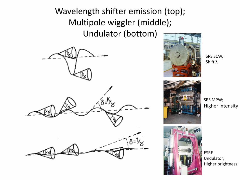
Wavelength shifter emission (top);Multipole wiggler (middle);
Undulator (bottom)
SRS SCW;Shift λ
SRS MPW;
Higher intensity
ESRF Undulator;Higher brightness
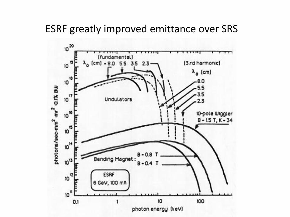
ESRF greatly improved emittance over SRS
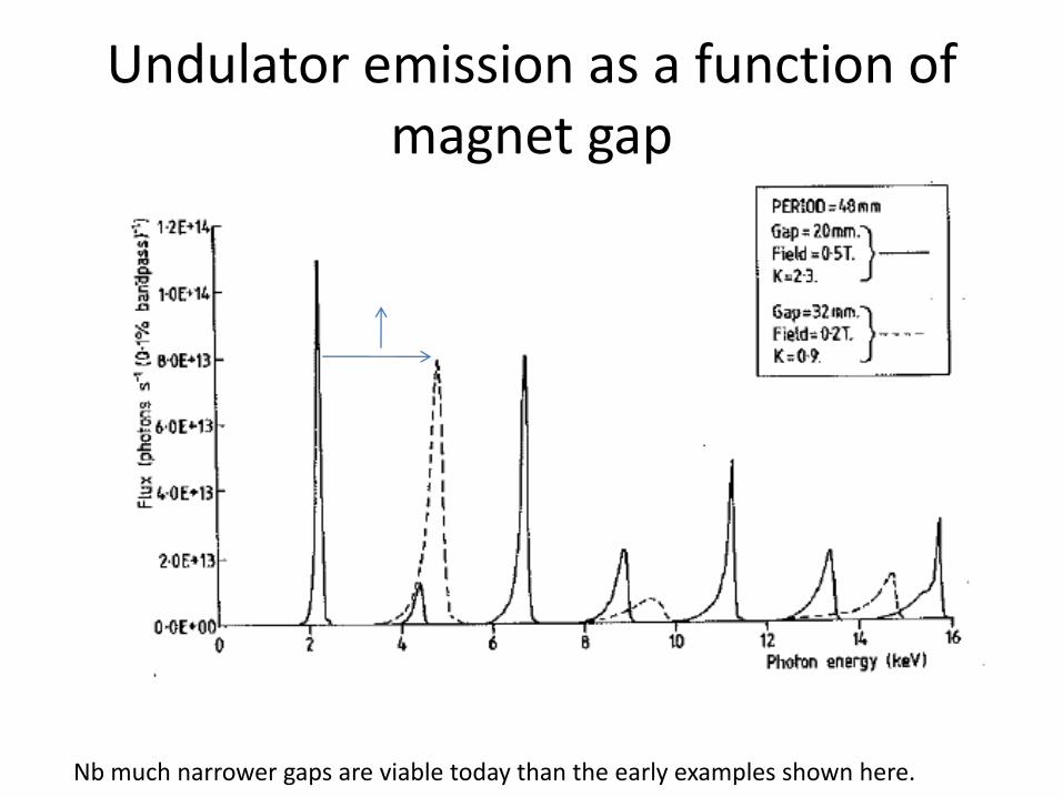
Undulator emission as a function of magnet gap
Nb much narrower gaps are viable today than the early examples shown here.
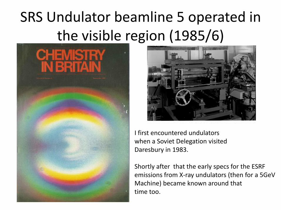
SRS Undulator beamline 5 operated in the visible region (1985/6)
I first encountered undulators when a Soviet Delegation visited Daresbury in 1983.
Shortly after that the early specs for the ESRF emissions from X-ray undulators (then for a 5GeV Machine) became known around that time too.

So we got our first SRS PX users and results>>>

Virus structures; a key step involved the methods…
SRS Station 7.2 and Hamburg ‘DESY’:-
Prof M G Rossmann, USA;In 1985, he became the first scientist to build a model of human rhinovirus-14, HRV-14, one of about 100 known cold virus strains. This was amongst the first group of virus crystal structures solved, and opened up studies of the most technically challenging projects.

Oscillation camera data processing was important especially with virus data; we re-examined the reflection rocking widths and partiality estimates with an SR source
T.J. Greenhough and J.R. Helliwell 'Oscillation camera data processing: reflecting range and prediction of partiality. II Synchrotron sources' (1982) J. Appl. Cryst. 15, 493-508.
Triangular monochromator based on the LURE and DESY design:
Lemonnier et al and Hendrix, Koch and Bordas
Helliwell et al J Phys E 1982 SRS 7.2
Phil Moore

The ‘single bounce’ monochromator can be curved to minimise the reflected bandpass ie case (b)
J R Helliwell 1984 'Synchrotron X-radiation protein crystallography: instrumentation, methods and applications' Reports on Progress in Physics 47, 1403-1497

Protein subunit A Protein subunit B
Calcium ion (weak anomalous peak)
Manganese ion (strong anomalous peak)
H. Einspahr, K. Suguna, F.L. Suddath, G.Ellis, J.R. Helliwell and M.Z. Papiz 'The location of the Mn:Ca ion cofactors in pea lectin crystals by use of
anomalous dispersion and tunable synchrotron X-radiation'. Acta. Cryst. (1985) B41, pp. 336-341.
Howard Einspahr
An early expt: In pea lectin Howard Einspahr wanted to know ‘which was Mn and which was Ca?’; the Mn K edge was accessible on SRS 7.2 at 1.896Ǻ; lets go for it!

Data collection at softer X-rays is viable; test experiments
(Helliwell 1983 unpublished) on lysozyme with the crystal
mounted in a mylar ‘roll-your-own-capillary’, used station
7.2 of the SRS and a wavelength of 2.6Å.
I had explored gradually longer wavelengths:- 1.488Å, 1.739Å, 1.86Å , 2.0Å ...
[Helliwell (1984) Reports on Progress in Physics 47, 1403-1497. ]

M. Cianci, P.J. Rizkallah, A. Olczak, J. Raftery, N.E. Chayen, P.F. Zagalsky and J.R. Helliwell"Structure of apocrustacyanin A1 using softer X-rays" (2001) Acta Cryst D57, 1219-1229.
Naomi ChayenMike Cianci
Crystallographic approach to solve apocrustacyanin A1:- SIROAS (Xe) and
softer X-rays (2 Å), and enhanced sulphur anomalous dispersion.

Beamline instrumentation at SRS 9.6
The SRS Super-conducting wiggler delivered 0.3kWatts into SRS 9.6 sufficient to melt lead!
Miroslav Papiz and the Enraf Nonius FAST TV diffractometer of Uli Arndt

David Stuart, virus crystallography
David pictured outside the Diamond Light Source Building
BTV was solved by David and his team using ESRF dataand FMDV using SRS 9.6 data. Hb of Max Perutz shown for a protein to virus size comparison.
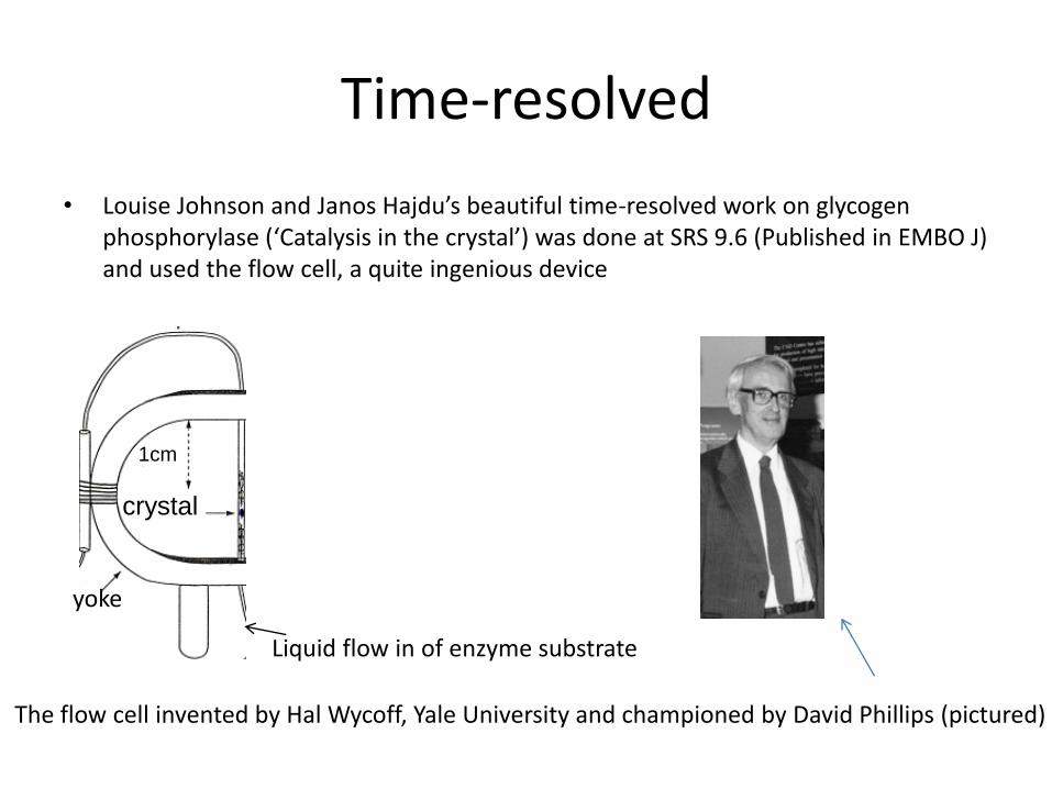
Time-resolved
• Louise Johnson and Janos Hajdu’s beautiful time-resolved work on glycogen phosphorylase (‘Catalysis in the crystal’) was done at SRS 9.6 (Published in EMBO J) and used the flow cell, a quite ingenious device
The flow cell invented by Hal Wycoff, Yale University and championed by David Phillips (pictured)
crystal
yoke
1cm
Liquid flow in of enzyme substrate
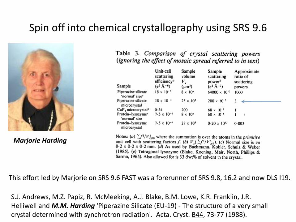
Spin off into chemical crystallography using SRS 9.6
S.J. Andrews, M.Z. Papiz, R. McMeeking, A.J. Blake, B.M. Lowe, K.R. Franklin, J.R. Helliwell and M.M. Harding 'Piperazine Silicate (EU-19) - The structure of a very small crystal determined with synchrotron radiation'. Acta. Cryst. B44, 73-77 (1988).
Marjorie Harding
This effort led by Marjorie on SRS 9.6 FAST was a forerunner of SRS 9.8, 16.2 and now DLS I19.

Daresbury Analytical and Research Technical Services (DARTS); an important aspect of the Economic Impact of the SRS
Pierre Rizkallah;Protein Crystallography Supply Manger for DARTS
E.J. Maclean, P.J. Rizkallah and J.R. Helliwell (2006). “Protein Crystallography and Synchrotron radiation; current status and future landscape” European Pharmaceutical Review Issue 2, p71-76
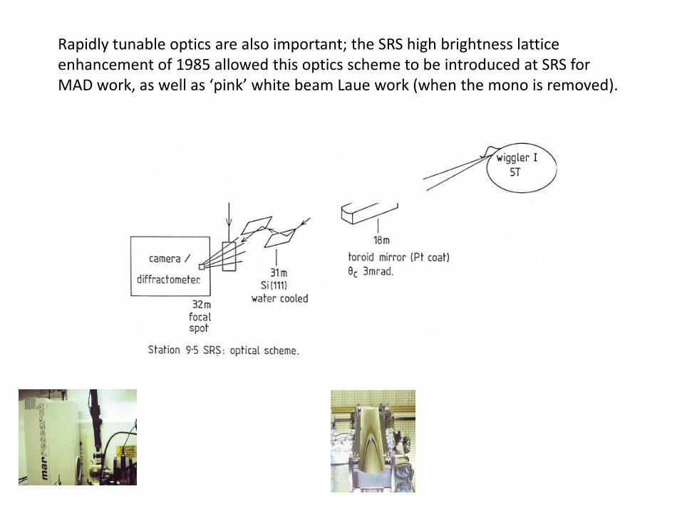
Rapidly tunable optics are also important; the SRS high brightness lattice enhancement of 1985 allowed this optics scheme to be introduced at SRS for MAD work, as well as ‘pink’ white beam Laue work (when the mono is removed).

This was a common monochromator type for EXAFS: the parallel double crystal monochromator
The closing of the slit jaws upstream of the monochromator is a simple means of reducing the divergence angle onto the first crystal of the monochromator; this is important when reducing δλ/ λ onto the sample.
How to solve the phase problem?
We measure a diffraction pattern, take the square roots of the intensities, but then we're stuck:
if we knew the phases we could simply compute a picture of the molecule, but we've lost the information in the experiment!
This is the phase problem, and a large part of crystallography is devotedto solving it.

Phasing Techniques
• Using isomorphous or anomalous differences
• Or from a substructure
• Or molecular replacement
• Or direct methods
http://www-structmed.cimr.cam.ac.uk/course.html

Another way to get three measurements: two wavelengths and an anomalous difference
R
I
FPH λ1-
FPH λ1+
FPH λ2-
This is equivalent to two isomorphous heavy atom derivatives.[Helliwell 1979 based on Okaya and Pepinsky 1956]

Now introduce selenomethionine in place of methionine
residues in a protein! Se K edge is at 0.98A wavelength

This use of multiple wavelengths (at least 2 or more) is called M.A.D.
• Selenomethionine protein production is now a reasonably straightforward technique of protein production.
• One in 57 amino acids, on average, is methionine.
• Intensity changes with wavelength are small but, being all on one crystal, viable to measure.
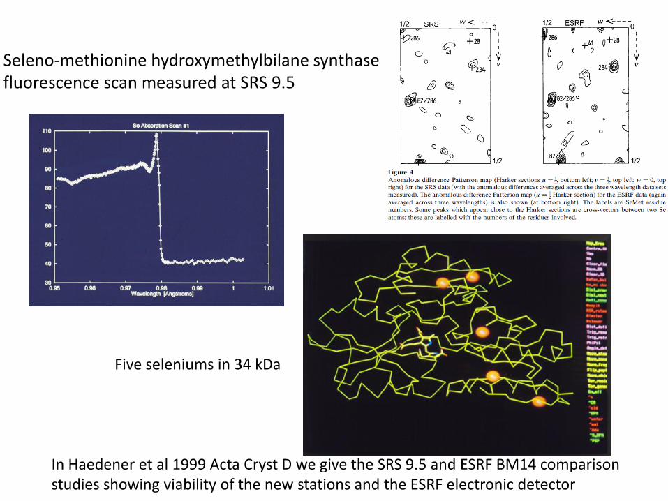
Seleno-methionine hydroxymethylbilane synthase fluorescence scan measured at SRS 9.5
Five seleniums in 34 kDa
In Haedener et al 1999 Acta Cryst D we give the SRS 9.5 and ESRF BM14 comparison studies showing viability of the new stations and the ESRF electronic detector
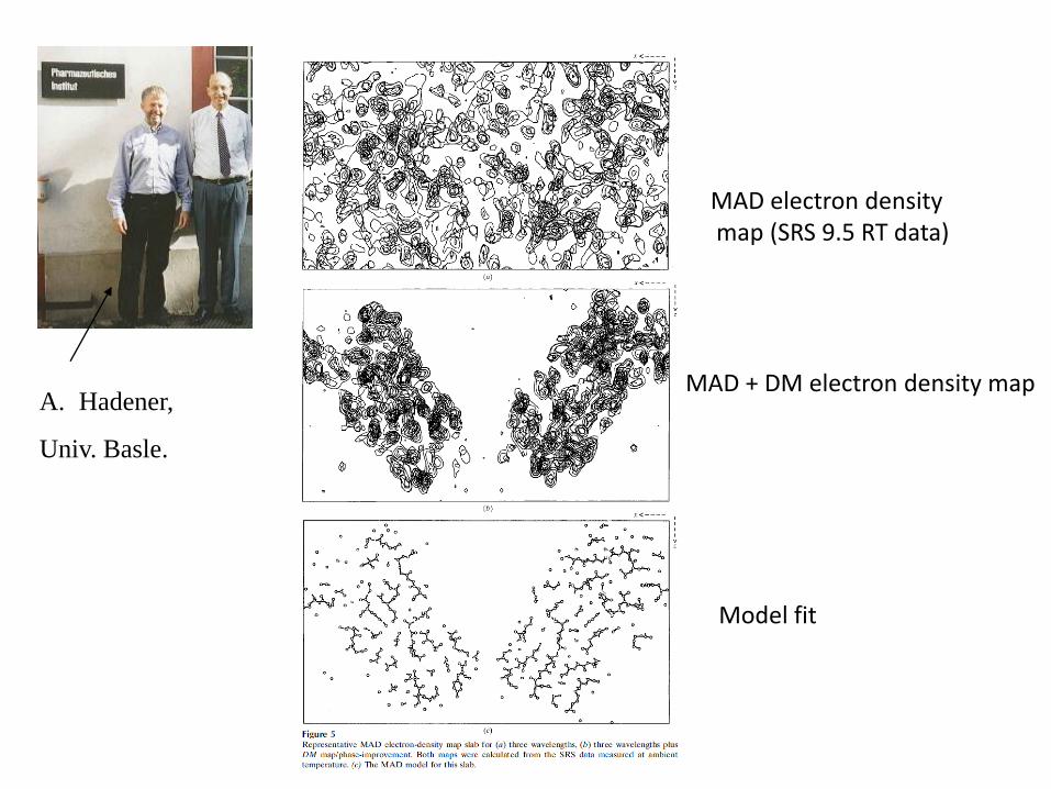
MAD electron densitymap (SRS 9.5 RT data)
MAD + DM electron density map
Model fit
A. Hadener,
Univ. Basle.

Lets now move in more detail towards the ‘New rings’ and especially ESRF planning
and implementation>>>

Multi-wavelength anomalous dispersion beam-line at ESRF (BL19 later called BM14) was the first PX
station at ESRF and with beamline optics based on SRS 9.5 . Andy Thompson left Daresbury to take
charge of this development at ESRF. It became the most productive MAD beamline for a long period.
The popularity of MAD methods rested on the relative ease of preparing seleno met proteins or use of metallated versions of a protein as well as sufficient beam intensity to work with small crystals to quickly measure multiple data sets. Cryo cooling was a breakthrough.

Stanford’s New Rings Workshops in the early to mid 1980s re use of PEP highlighted the need for test assessments of such beams; a NATO Collaborative Research Award with SSRL Stanford led to some pretty seminal work
Keith HodgsonBritt Hedman
Focussing of the full SRS wiggler white X-ray beam onto a 20 microns gramicidin test crystal sample to simulate the proposed monochromatic undulator ESRF X-ray intensities to test if microcrystals of biological macromolecules
would withstand the X-ray thermal and radiation blast.

Alignment of the beam onto the crystal is critical; we are taught this from an early age
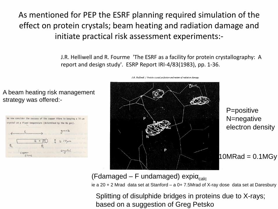
As mentioned for PEP the ESRF planning required simulation of the effect on protein crystals; beam heating and radiation damage and
initiate practical risk assessment experiments:-
J.R. Helliwell and R. Fourme 'The ESRF as a facility for protein crystallography: A report and design study'. ESRP Report IRI-4/83(1983), pp. 1-36.
Splitting of disulphide bridges in proteins due to X-rays;
based on a suggestion of Greg Petsko
P=positive
N=negative
electron density
(Fdamaged – F undamaged) expiαcalc
ie a 20 + 2 Mrad data set at Stanford – a 0+ 7.5Mrad of X-ray dose data set at Daresbury
10MRad = 0.1MGy
A beam heating risk management
strategy was offered:-

The European Synchrotron Radiation Facility (ESRF) in Grenoble & the Institut Laue
Langevin nuclear reactor is to the right
Neutron
source
ESRF
ESRF knowledge greatly helped DLS design and build
ESRF developed ‘Phase I beamline’s that were generic ie X-ray undulators for high
brilliance applications such as virus crystallography, a microfocus beamline for
micro-crystallography or tiny fibres for fibre diffraction or microbeam scanning and a white
beam beamline for time-resolved Laue.
EMBL developed with ESRF the micro-crystallography diffractometer.

Sub-nanosecond time-resolved Laue protein crystallography (eg see Srajer et al Science1996:
Vol. 274 no. 5293 pp. 1726-1729 )
Movie kindly provided by Michael Wulff, ESRF; research pioneered with
Keith Moffat and later Phil Anfinrud.
Interpretation of Laue diffraction patterns involves more steps compared with monochromatic diffraction
• Wavelength normalisation;
• The presence of multiple reflections spots means that their component intensities have to be extracted out;
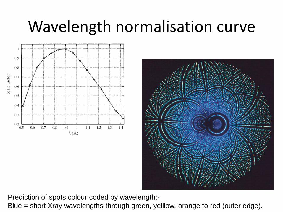
Wavelength normalisation curve
Prediction of spots colour coded by wavelength:-
Blue = short Xray wavelengths through green, yelllow, orange to red (outer edge).

The Ewald Sphere Construction; reminder
Shaded = the stimulated region of reciprocal space by the incident wavelength bandpass, λmin to λmax
Stimulated reciprocal latticepoints
D.W.J. Cruickshank, J.R. Helliwell and K. Moffat 'Multiplicity Distribution of Reflections in Laue Diffraction' Acta. Cryst. A43, 656-674 (1987)
This will be a multiple reflections containing diffraction spot
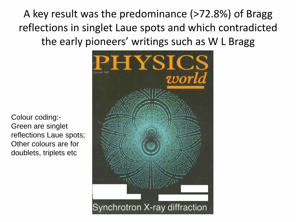
A key result was the predominance (>72.8%) of Bragg reflections in singlet Laue spots and which contradicted
the early pioneers’ writings such as W L Bragg
Colour coding:-
Green are singlet
reflections Laue spots;
Other colours are for
doublets, triplets etc

We conducted many studies to validate the method and the Daresbury software eg:-
Zygmunt
Derewenda
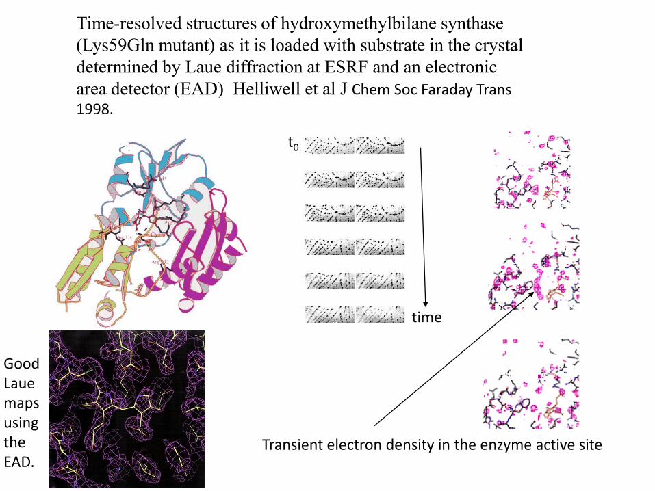
Time-resolved structures of hydroxymethylbilane synthase
(Lys59Gln mutant) as it is loaded with substrate in the crystal
determined by Laue diffraction at ESRF and an electronic
area detector (EAD) Helliwell et al J Chem Soc Faraday Trans 1998.
t0
time
Transient electron density in the enzyme active site
Good Lauemaps using the EAD.

The Laue method was enthusiastically taken up at the Grenoble neutron source>>>

X-rays; Scattered from electronsproportional to Z (red). Neutrons; scattered from nuclei & evenly across all elements (green)
H B C O Al Si P Ti D
1 5 6 8 13 14 15 22 1
-37.4 53.0 66.5 58.0 34.5 41.5 51.3 -34.4 66.7
X-rays and neutrons
Large difference in the neutron cross-section among isotopes
Neutron diffraction can be used to directly determine the
positions of H-isotopes at medium resolutions (~2.5 Ǻ) !
!

The EMBL Laue Diffractometer at ILL; LADI I left LADI III right
> Gd2O3-doped neutron sensitive image plate.
> Typical wavelength range: ~ 2.7 – 3.6 Å.
> Narrow (25%0 bandpass – 99% spots single.
> Scanned phonographically.
Neutron Laue data are processed with the ‘Daresbury Laue software’.
Peter Timmins

Bound water oxygen and deuterium atoms resolved with neutrons including at liquid helium temp!
M.P. Blakeley, A.J. Kalb (Gilboa), J.R. Helliwell & D.A.A. Myles (2004)
"The 15-K neutron structure of saccharide free concanavalin A"
Proceedings of the National Academy of Sciences USA 101, 16405-16410.
5-10 15-20 25-30 35-40 45-50 55-60 65-70 75-80
0
5
10
15
20
25
30
35
40
45
50
55
60
65
70
75
80
85
90
95
Num
ber
of
wat
er a
tom
s obse
rved
B-factor range
293K D2O
293K DO or O-only
12K D2O
12K O-only
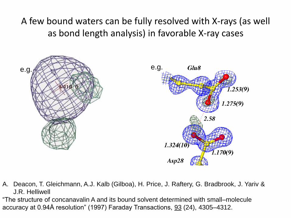
A few bound waters can be fully resolved with X-rays (as well as bond length analysis) in favorable X-ray cases
A. Deacon, T. Gleichmann, A.J. Kalb (Gilboa), H. Price, J. Raftery, G. Bradbrook, J. Yariv &
J.R. Helliwell
“The structure of concanavalin A and its bound solvent determined with small–molecule
accuracy at 0.94Å resolution” (1997) Faraday Transactions, 93 (24), 4305–4312.
e.g.e.g.
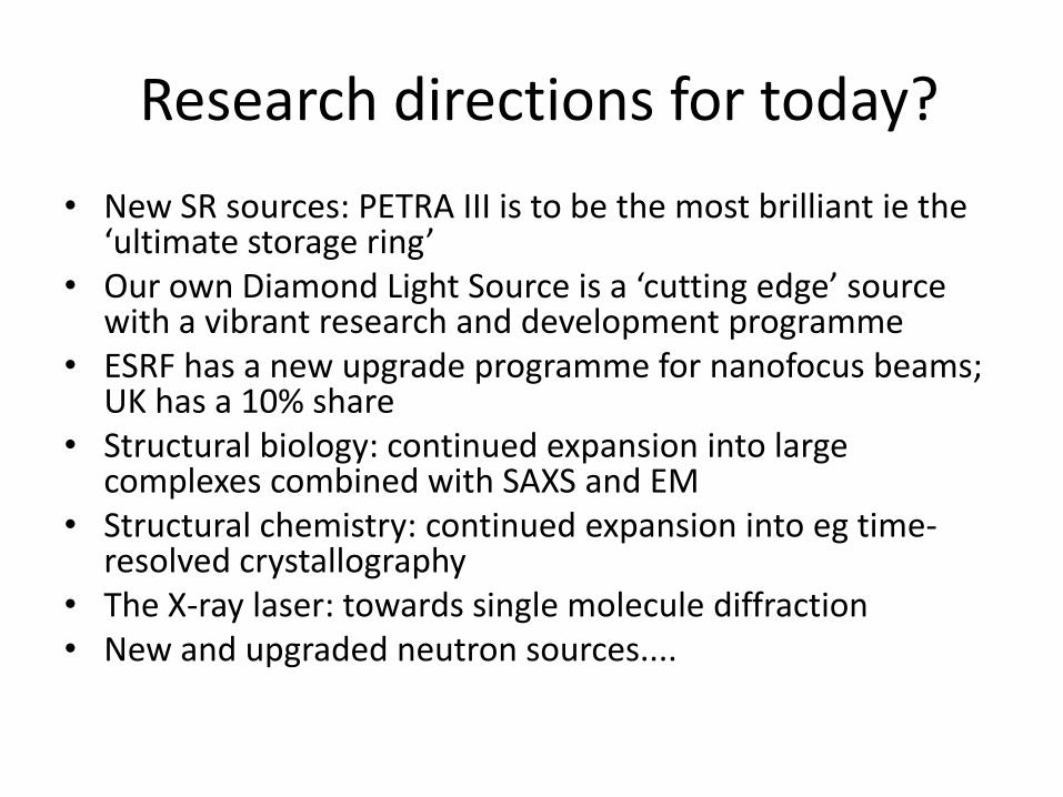
Research directions for today?
• New SR sources: PETRA III is to be the most brilliant ie the ‘ultimate storage ring’
• Our own Diamond Light Source is a ‘cutting edge’ source with a vibrant research and development programme
• ESRF has a new upgrade programme for nanofocus beams; UK has a 10% share
• Structural biology: continued expansion into large complexes combined with SAXS and EM
• Structural chemistry: continued expansion into eg time-resolved crystallography
• The X-ray laser: towards single molecule diffraction• New and upgraded neutron sources....

Acknowledgements especially to:-
• To all my coauthors and collaborators and PhD students for all our joint work together during the decades;
• To the University of Manchester (since 1989) and Daresbury Laboratory (since 1976), but also the ESRF and the Institut Laue Langevin for stimulating environments, as well as my stays at the Universities of York, Oxford and Keele Universities;
• To the various funding agencies a heartfelt thank you!