Embed Size (px)
Citation preview
REEF JOURNAL
Vol. 1, No. 1 2009 Page 1
The Evolution of Multi-Celled Sand-Filled
Geosynthetic Systems for
Coastal Protection and Surfing Enhancement
Lee E. Harris1
and Jay W. Sample2
1Associate Professor of Ocean Engineering
Department of Marine and Environmental Systems
Florida Institute of Technology Melbourne, Florida 32901
2President, Advanced Coastal Technology, Inc.
3335 Camp Branch Road, Topton, NC 28781
ABSTRACT
This paper reviews the development of sand and water-filled geosynthetic container systems
for coastal erosion control, storm protection, and artificial reefs. The use of sand-filled
containers in the design and construction of coastal protective structures has increased
significantly in recent years due to the improvements in geosynthetic materials, development
of engineered systems, and the desire for “softer” and more “user-friendly” forms of shore
protective structures. The use of sand-filled geosynthetic containers on sandy recreational
beaches has proven to be more “user friendly” than the more traditional “hard structures” such
as vertical seawalls and sloped revetments constructed of rock and concrete, which can
impede recreational uses of these areas. These improved geosynthetic systems have resulted
in the development and implementation of sand-filled container systems which provide
significant levels of storm and coastal erosion protection, as evidenced by the performance
during the four major hurricanes impacting Florida in 2004. In addition to the historical
developments and coastal engineering applications of these systems, unique container shapes,
materials, and designs are being developed for constructing submerged artificial reefs for both
shoreline stabilization and recreational amenities including surfing enhancement.
ADDITIONAL INDEX WORDS: Geosynthetics, geotextiles, sand-filled containers,
geotubes, geosystems, geocontainers, submerged breakwaters, sills, artificial surfing reefs.
INTRODUCTION
The concept of employing sand filled containers of various sizes and shapes for erosion
control has been in existence for centuries (KOERNER, 1998). The initial evolution of sand-
filled containers for coastal erosion control has occurred over the past four hundred years,
since the Dutch first employed small sand-filled containers to shore up their dike and dam
structures in the 17th
century. The myriad of enormous dikes surrounding Holland provide
continuous protection to a nation which is sited largely below sea level.
The earliest fabrics employed in the containment of sand for the construction of dikes and
levees were degradable natural materials which suffered from severe limitations, but the
development of synthetic fibers has provided stronger and more durable materials. The
problems with sand-filled container systems have been and continue to be related to
REEF JOURNAL
Vol. 1, No. 1 2009 Page 2
inadequacies of the fabric materials and seams containing the sand fill, insufficient size and
mass of the containers to withstand larger wave forces, and inappropriate container shapes
which reflect rather than attenuate wave energy.
Recent improvements in geosynthetic materials and fabrication techniques have resulted in
increased strengths and durability, allowing improved designs and performance of sand-filled
container systems. State-of-the-art geosynthetic fabrics today combine high strengths and
resistance to abrasion, puncture, tear, and ultraviolet deterioration, as well as site specific
characteristics such as the ability to be colored to match the beach sand at a project area.
Sandbags and geotextile containers have also been used to construct harder, more rigid
structures by filling them with grout or concrete. In these applications, the primary function of
the container material is to provide a temporary form within which the concrete can harden. If
the concrete-filled fabric units are joined together utilizing steel or other
connecting/reinforcing elements, the engineering design and performance of these concrete-
filled container structures is similar to that of articulated mats or other concrete structures. If
no connecting elements are employed, the design and performance of the individual units is
similar to other rock or concrete unit rubble-mound structures. Only water and sand filled
containers are covered in this paper.
TYPES OF MATERIALS AND CONTAINER DESIGNS
Geosynthetic materials are fabrics which have been specifically created for use in, on, under
and around the earth. Specialized materials have been developed in order to withstand the
harsh marine conditions including exposure to waves, water-born debris, storm surge, sand
abrasion, and sunlight. These geosynthetic materials include both geotextile (porous) and
geomembrane (non-porous) materials that are fabricated into very large containers that can be
filled with sand and used for many applications, including systems for shoreline stabilization
(TRANIER, et al., 1997).
The term “sand-filled container” (SFC) is used to differentiate between the smaller “sand-
bags” whose small sizes limit slope stabilization applications to inland waterways, and the
larger “sand-filled containers” with increased sizes allowing them to be utilized on the open
ocean coast. Terms used to refer to these containers have included bags, sandbags, geobags,
sausages, tubes, geotubes, geocontainers, geosystems, etc., some of which are being used as
registered trade names. The standard small sand-bags are filled with approximately 0.03 cubic
meters (1.0 cubic foot) of sand, and weigh approximately 40 kilograms (90 pounds) each
(HARRIS, 1987). This allows filling of the small sand-bags first, with subsequent
transportation and placement at another location. However, the small sizes and weights of
these sandbags limit their use and effectiveness. For open ocean exposure sites, extremely
large sand-filled containers are now available in lengths of over 100 meters (328 feet) and in
widths or diameters of over 5 meters (16.4 feet).
Several types of materials and container systems have been developed specifically for the
design of coastal erosion protection systems (PILARCZYK, 1996) and for beneficial uses of
dredged material (HARRIS, 1994). Sand-filled containers have been utilized to construct a
variety of traditional coastal erosion control structures, including both shore-perpendicular
and shore-parallel structures. These systems have included jetties, groins, vertical seawalls,
sloped revetments, breakwaters and sill structures with varying degrees of success (U.S.
ARMY CORPS OF ENGINEERS, 1981; and ZADIKOFF, et al., 1998). Due to the lower
REEF JOURNAL
Vol. 1, No. 1 2009 Page 3
costs and less need for heavy equipment, sand-filled containers have been used in developing
countries (HARRIS and ZADIKOFF, 1999).
Due to the large sizes and weights, the larger sand-filled containers must be filled in-situ – the
container is positioned in its final design position first while empty, with subsequent filling.
The exception to in-situ filling is the use of a split hull barge, in which the geosynthetic fabric
is laid in the barge, the sand placed on top, the material wrapped around the sand and seamed,
and final offshore placement made by dropping the containers through the bottom of the barge
(see e.g. TRANIER, et al., 1997 and BEZUIJEN, et al., 2000). The disadvantages of the split-
hull barge method of installation are (HARRIS, et al., 2004):
1. the difficulty in constructing a smooth overall design profile,
2. the difficulty in precise placement of the containers,
3. the inability to construct the top of the structure any higher than the draft of the barge,
4. the requirement that the seams be made in the barge after the sand is placed, rather
than in the controlled environment of a factory.
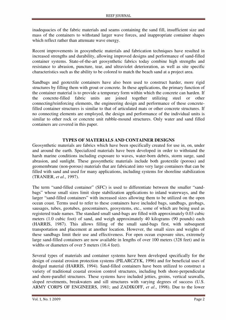
In-situ filling of the containers is done by pumping a sand-water slurry into the pre-fabricated
container. For a geotextile material, the water flows out through the permeable fabric leaving
the sand behind, and for an impermeable geomembrane material, exit ports are temporarily
installed to allow the water to exit. An advantage in using an impermeable geomembrane
material for the container is that the container can be filled rapidly first with only water, so
that the container takes on its full shape, and then the water can subsequently be displaced
with sand. Figure 1 shows the in-situ filling of a sand-filled geomembrane container using fill
and exit ports.
Figure 1. In-situ filling of one multi-celled geomembrane container above water (left) and in-
situ filling of single-celled geotextile container underwater (right).
Sand-filled Container Shapes
For purposes of engineering design, sand-filled containers can be classified into two basic
shapes:
1. Two-dimensional “pillow-shaped” or single-celled (as shown in Figure 2), and
2. Three-dimensional or “multi-celled” (as shown in Figure 1).
REEF JOURNAL
Vol. 1, No. 1 2009 Page 4
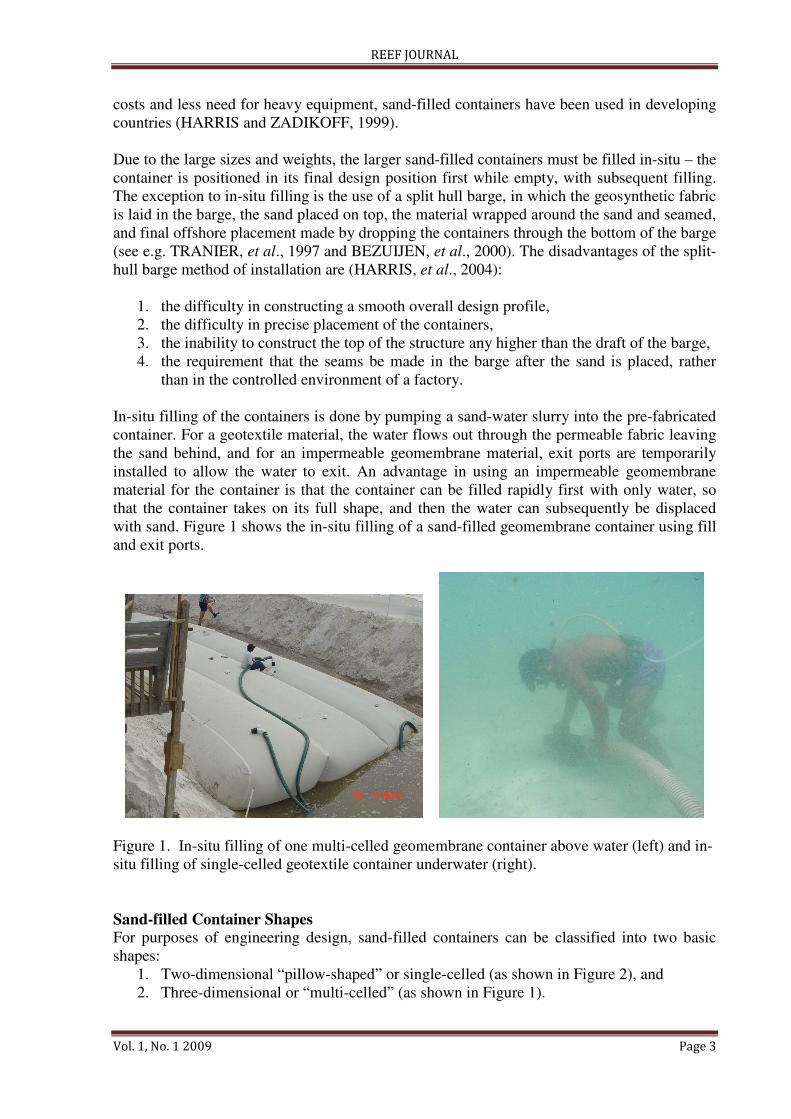
The simplest container or tube can be fabricated from a single piece of fabric folded over with
sewn seams to connect the edges, similar to a pillow case. When empty this container is a 2-D
flat shape, and when filled with sand this container will take on an approximate elliptical
shape, as shown in the photographs in Figure 2. Multi-cell containers use internal web and
end panels, so that they will take a precise shape when filled with sand, as shown in Figure 1.
Figure 2. Two-dimensional sand-filled container installation at Fort Pierce, Florida.
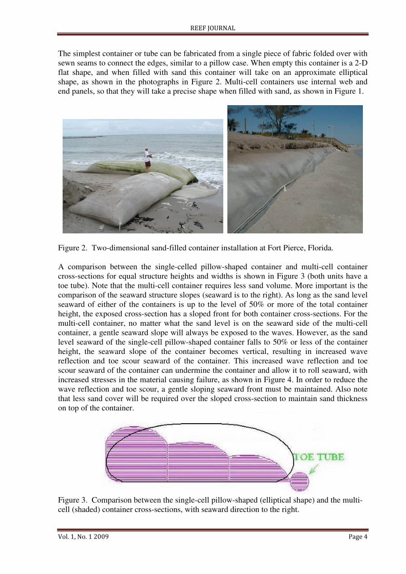
A comparison between the single-celled pillow-shaped container and multi-cell container
cross-sections for equal structure heights and widths is shown in Figure 3 (both units have a
toe tube). Note that the multi-cell container requires less sand volume. More important is the
comparison of the seaward structure slopes (seaward is to the right). As long as the sand level
seaward of either of the containers is up to the level of 50% or more of the total container
height, the exposed cross-section has a sloped front for both container cross-sections. For the
multi-cell container, no matter what the sand level is on the seaward side of the multi-cell
container, a gentle seaward slope will always be exposed to the waves. However, as the sand
level seaward of the single-cell pillow-shaped container falls to 50% or less of the container
height, the seaward slope of the container becomes vertical, resulting in increased wave
reflection and toe scour seaward of the container. This increased wave reflection and toe
scour seaward of the container can undermine the container and allow it to roll seaward, with
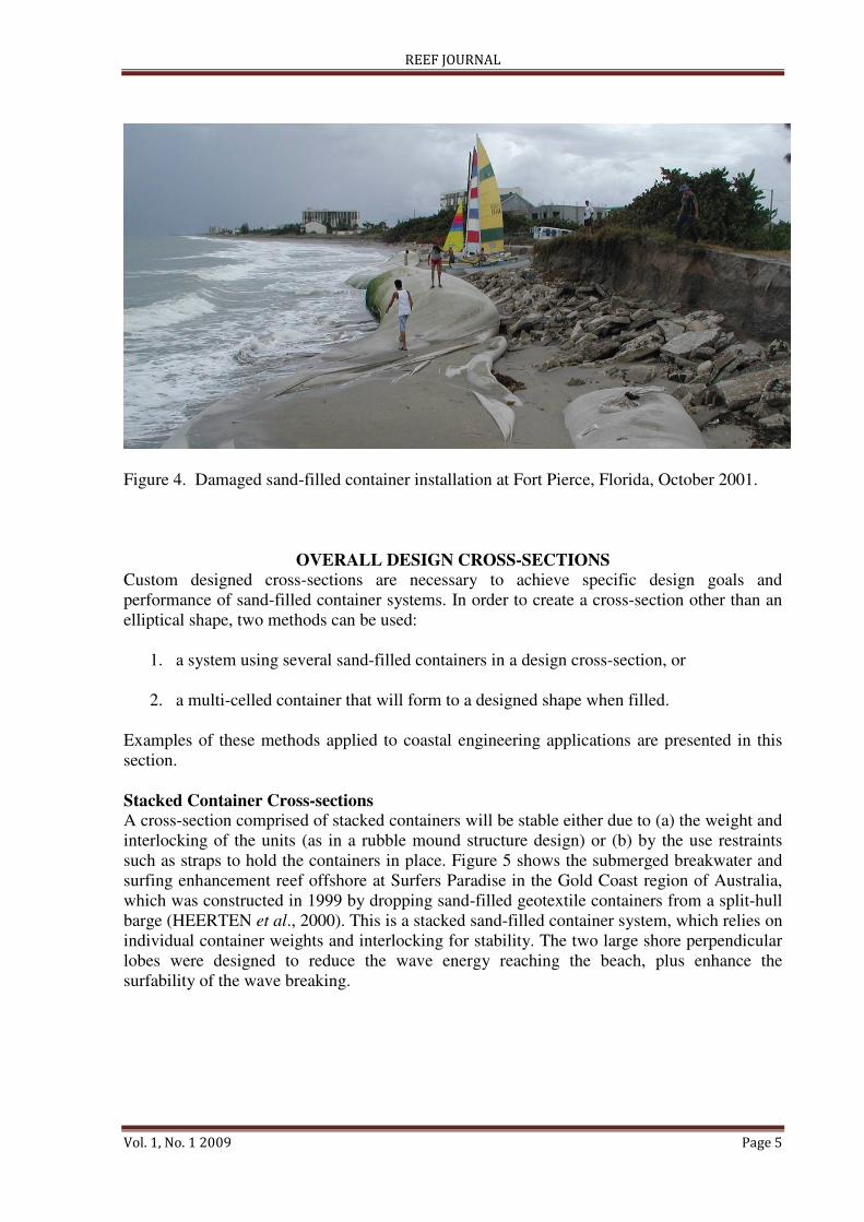
increased stresses in the material causing failure, as shown in Figure 4. In order to reduce the
wave reflection and toe scour, a gentle sloping seaward front must be maintained. Also note
that less sand cover will be required over the sloped cross-section to maintain sand thickness
on top of the container.
Figure 3. Comparison between the single-cell pillow-shaped (elliptical shape) and the multi-
cell (shaded) container cross-sections, with seaward direction to the right.
REEF JOURNAL
Vol. 1, No. 1 2009 Page 5
Figure 4. Damaged sand-filled container installation at Fort Pierce, Florida, October 2001.
OVERALL DESIGN CROSS-SECTIONS
Custom designed cross-sections are necessary to achieve specific design goals and
performance of sand-filled container systems. In order to create a cross-section other than an
elliptical shape, two methods can be used:
1. a system using several sand-filled containers in a design cross-section, or
2. a multi-celled container that will form to a designed shape when filled.
Examples of these methods applied to coastal engineering applications are presented in this
section.
Stacked Container Cross-sections
A cross-section comprised of stacked containers will be stable either due to (a) the weight and
interlocking of the units (as in a rubble mound structure design) or (b) by the use restraints
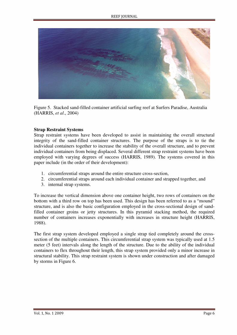
such as straps to hold the containers in place. Figure 5 shows the submerged breakwater and
surfing enhancement reef offshore at Surfers Paradise in the Gold Coast region of Australia,
which was constructed in 1999 by dropping sand-filled geotextile containers from a split-hull
barge (HEERTEN et al., 2000). This is a stacked sand-filled container system, which relies on
individual container weights and interlocking for stability. The two large shore perpendicular
lobes were designed to reduce the wave energy reaching the beach, plus enhance the
surfability of the wave breaking.
REEF JOURNAL
Vol. 1, No. 1 2009 Page 6
Figure 5. Stacked sand-filled container artificial surfing reef at Surfers Paradise, Australia
(HARRIS, et al., 2004)
Strap Restraint Systems
Strap restraint systems have been developed to assist in maintaining the overall structural
integrity of the sand-filled container structures. The purpose of the straps is to tie the
individual containers together to increase the stability of the overall structure, and to prevent
individual containers from being displaced. Several different strap restraint systems have been
employed with varying degrees of success (HARRIS, 1989). The systems covered in this
paper include (in the order of their development):
1. circumferential straps around the entire structure cross-section,
2. circumferential straps around each individual container and strapped together, and
3. internal strap systems.
To increase the vertical dimension above one container height, two rows of containers on the
bottom with a third row on top has been used. This design has been referred to as a “mound”
structure, and is also the basic configuration employed in the cross-sectional design of sand-
filled container groins or jetty structures. In this pyramid stacking method, the required
number of containers increases exponentially with increases in structure height (HARRIS,
1988).
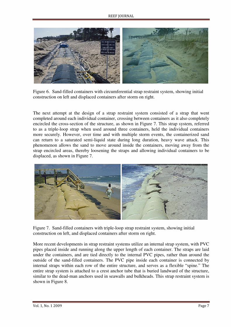
The first strap system developed employed a single strap tied completely around the cross-
section of the multiple containers. This circumferential strap system was typically used at 1.5
meter (5 feet) intervals along the length of the structure. Due to the ability of the individual
containers to flex throughout their length, this strap system provided only a minor increase in
structural stability. This strap restraint system is shown under construction and after damaged
by storms in Figure 6.
REEF JOURNAL
Vol. 1, No. 1 2009 Page 7
Figure 6. Sand-filled containers with circumferential strap restraint system, showing initial
construction on left and displaced containers after storm on right.
The next attempt at the design of a strap restraint system consisted of a strap that went
completed around each individual container, crossing between containers as it also completely
encircled the cross-section of the structure, as shown in Figure 7. This strap system, referred
to as a triple-loop strap when used around three containers, held the individual containers
more securely. However, over time and with multiple storm events, the containerized sand
can return to a saturated semi-liquid state during long duration, heavy wave attack. This
phenomenon allows the sand to move around inside the containers, moving away from the
strap encircled areas, thereby loosening the straps and allowing individual containers to be
displaced, as shown in Figure 7.
Figure 7. Sand-filled containers with triple-loop strap restraint system, showing initial
construction on left, and displaced containers after storm on right.
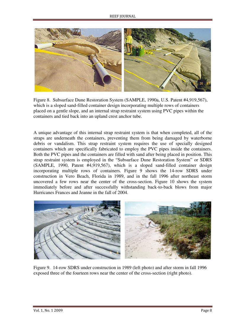
More recent developments in strap restraint systems utilize an internal strap system, with PVC
pipes placed inside and running along the upper length of each container. The straps are laid
under the containers, and are tied directly to the internal PVC pipes, rather than around the
outside of the sand-filled containers. The PVC pipe inside each container is connected by
internal straps within each row of the entire structure, and serves as a flexible “spine.” The
entire strap system is attached to a crest anchor tube that is buried landward of the structure,
similar to the dead-man anchors used in seawalls and bulkheads. This strap restraint system is
shown in Figure 8.
REEF JOURNAL
Vol. 1, No. 1 2009 Page 8
Figure 8. Subsurface Dune Restoration System (SAMPLE, 1990a, U.S. Patent #4,919,567),
which is a sloped sand-filled container design incorporating multiple rows of containers
placed on a gentle slope, and an internal strap restraint system using PVC pipes within the
containers and tied back into an upland crest anchor tube.
A unique advantage of this internal strap restraint system is that when completed, all of the
straps are underneath the containers, preventing them from being damaged by waterborne
debris or vandalism. This strap restraint system requires the use of specially designed
containers which are specifically fabricated to employ the PVC pipes inside the containers.
Both the PVC pipes and the containers are filled with sand after being placed in position. This
strap restraint system is employed in the “Subsurface Dune Restoration System” or SDRS
(SAMPLE, 1990, Patent #4,919,567), which is a sloped sand-filled container design
incorporating multiple rows of containers. Figure 9 shows the 14-row SDRS under
construction in Vero Beach, Florida in 1989, and in the fall 1996 after northeast storm
uncovered a few rows near the center of the cross-section. Figure 10 shows the system
immediately before and after successfully withstanding back-to-back blows from major
Hurricanes Frances and Jeanne in the fall of 2004.
Figure 9. 14-row SDRS under construction in 1989 (left photo) and after storm in fall 1996
exposed three of the fourteen rows near the center of the cross-section (right photo).
REEF JOURNAL
Vol. 1, No. 1 2009 Page 9
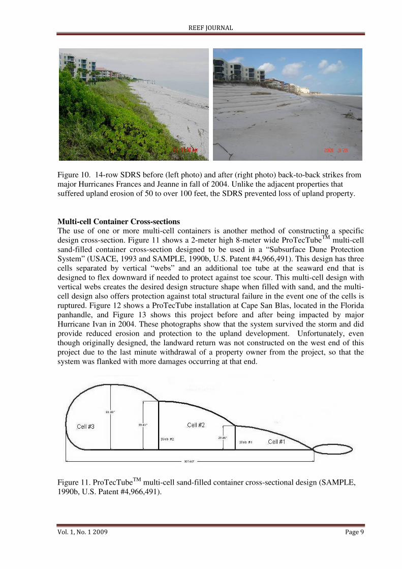
Figure 10. 14-row SDRS before (left photo) and after (right photo) back-to-back strikes from
major Hurricanes Frances and Jeanne in fall of 2004. Unlike the adjacent properties that
suffered upland erosion of 50 to over 100 feet, the SDRS prevented loss of upland property.
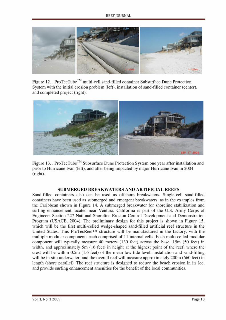
Multi-cell Container Cross-sections
The use of one or more multi-cell containers is another method of constructing a specific
design cross-section. Figure 11 shows a 2-meter high 8-meter wide ProTecTubeTM
multi-cell
sand-filled container cross-section designed to be used in a “Subsurface Dune Protection
System” (USACE, 1993 and SAMPLE, 1990b, U.S. Patent #4,966,491). This design has three
cells separated by vertical “webs” and an additional toe tube at the seaward end that is
designed to flex downward if needed to protect against toe scour. This multi-cell design with
vertical webs creates the desired design structure shape when filled with sand, and the multi-
cell design also offers protection against total structural failure in the event one of the cells is
ruptured. Figure 12 shows a ProTecTube installation at Cape San Blas, located in the Florida
panhandle, and Figure 13 shows this project before and after being impacted by major
Hurricane Ivan in 2004. These photographs show that the system survived the storm and did
provide reduced erosion and protection to the upland development. Unfortunately, even
though originally designed, the landward return was not constructed on the west end of this
project due to the last minute withdrawal of a property owner from the project, so that the
system was flanked with more damages occurring at that end.
Figure 11. ProTecTube
TM multi-cell sand-filled container cross-sectional design (SAMPLE,
1990b, U.S. Patent #4,966,491).
REEF JOURNAL
Vol. 1, No. 1 2009 Page 10
Figure 12. . ProTecTubeTM
multi-cell sand-filled container Subsurface Dune Protection
System with the initial erosion problem (left), installation of sand-filled container (center),
and completed project (right).
Figure 13. . ProTecTubeTM
Subsurface Dune Protection System one year after installation and
prior to Hurricane Ivan (left), and after being impacted by major Hurricane Ivan in 2004
(right).
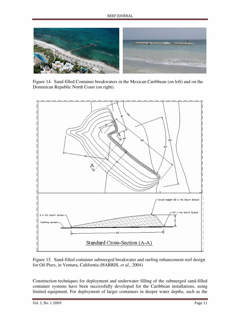
SUBMERGED BREAKWATERS AND ARTIFICIAL REEFS
Sand-filled containers also can be used as offshore breakwaters. Single-cell sand-filled
containers have been used as submerged and emergent breakwaters, as in the examples from
the Caribbean shown in Figure 14. A submerged breakwater for shoreline stabilization and
surfing enhancement located near Ventura, California is part of the U.S. Army Corps of
Engineers Section 227 National Shoreline Erosion Control Development and Demonstration
Program (USACE, 2004). The preliminary design for this project is shown in Figure 15,
which will be the first multi-celled wedge-shaped sand-filled artificial reef structure in the
United States. This ProTecReef™ structure will be manufactured in the factory, with the
multiple modular components each comprised of 11 internal cells. Each multi-celled modular
component will typically measure 40 meters (130 feet) across the base, 15m (50 feet) in
width, and approximately 5m (16 feet) in height at the highest point of the reef, where the
crest will be within 0.5m (1.6 feet) of the mean low tide level. Installation and sand-filling
will be in-situ underwater; and the overall reef will measure approximately 200m (660 feet) in
length (shore parallel). The reef structure is designed to reduce the beach erosion in its lee,
and provide surfing enhancement amenities for the benefit of the local communities.
REEF JOURNAL
Vol. 1, No. 1 2009 Page 11
Figure 14. Sand-filled Container breakwaters in the Mexican Caribbean (on left) and on the
Dominican Republic North Coast (on right).
Figure 15. Sand-filled container submerged breakwater and surfing enhancement reef design
for Oil Piers, in Ventura, California (HARRIS, et al., 2004)
Construction techniques for deployment and underwater filling of the submerged sand-filled
container systems have been successfully developed for the Caribbean installations, using
limited equipment. For deployment of larger containers in deeper water depths, such as the
REEF JOURNAL
Vol. 1, No. 1 2009 Page 12
one planned for Ventura California, barges and tugboats will be required. The Rapidly
Installed Breakwater (R.I.B.) project, which is an experimental water-filled geomembrane
container floating breakwater system designed for deployment within 48 hours and tested by
the U.S. Army Corps of Engineers offshore Florida’s central east coast in recent years
(USACE, 2003), provides additional techniques that can be extended to deployments of other
large offshore water and sand-filled container systems.
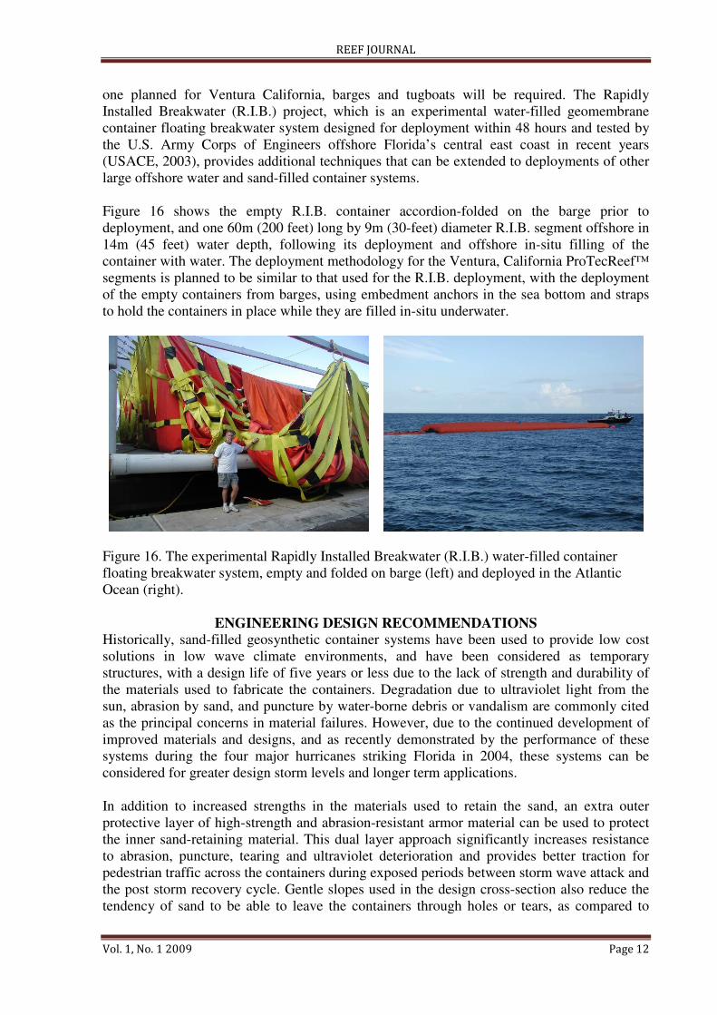
Figure 16 shows the empty R.I.B. container accordion-folded on the barge prior to
deployment, and one 60m (200 feet) long by 9m (30-feet) diameter R.I.B. segment offshore in
14m (45 feet) water depth, following its deployment and offshore in-situ filling of the
container with water. The deployment methodology for the Ventura, California ProTecReef™
segments is planned to be similar to that used for the R.I.B. deployment, with the deployment
of the empty containers from barges, using embedment anchors in the sea bottom and straps
to hold the containers in place while they are filled in-situ underwater.
Figure 16. The experimental Rapidly Installed Breakwater (R.I.B.) water-filled container
floating breakwater system, empty and folded on barge (left) and deployed in the Atlantic
Ocean (right).
ENGINEERING DESIGN RECOMMENDATIONS
Historically, sand-filled geosynthetic container systems have been used to provide low cost
solutions in low wave climate environments, and have been considered as temporary
structures, with a design life of five years or less due to the lack of strength and durability of
the materials used to fabricate the containers. Degradation due to ultraviolet light from the
sun, abrasion by sand, and puncture by water-borne debris or vandalism are commonly cited
as the principal concerns in material failures. However, due to the continued development of
improved materials and designs, and as recently demonstrated by the performance of these
systems during the four major hurricanes striking Florida in 2004, these systems can be
considered for greater design storm levels and longer term applications.
In addition to increased strengths in the materials used to retain the sand, an extra outer
protective layer of high-strength and abrasion-resistant armor material can be used to protect
the inner sand-retaining material. This dual layer approach significantly increases resistance
to abrasion, puncture, tearing and ultraviolet deterioration and provides better traction for
pedestrian traffic across the containers during exposed periods between storm wave attack and
the post storm recovery cycle. Gentle slopes used in the design cross-section also reduce the
tendency of sand to be able to leave the containers through holes or tears, as compared to
REEF JOURNAL
Vol. 1, No. 1 2009 Page 13
vertical faces. Failure of the seams of the containers has been another problem that can be
addressed in the fabrication process.
The engineering design considerations for sand-filled container systems are similar to those
for traditional coastal structures: they can be designed with crest elevations to resist or
minimize wave run-up, overtopping, and wave transmission; with adequate toe penetration
(base elevation) to resist undercutting and toe scour; and with adequate returns at the ends of
the project to avoid flanking. Due to the smaller specific weight of sand compared to rocks, as
well as the flexibility of an individual sand-filled container, a more gentle slope is
recommended for the overall sand-filled container structures. The 3 or 4 horizontal to 1
vertical slope has functioned well in sand-filled container systems constructed in Florida,
compared to the steeper 1.5 or 2 H to 1 V slopes commonly used for rock structures
(HARRIS, 2003).
Analysis of the stability of sand-filled container structures is more difficult than with rigid
units such as rock or concrete, as the sand within the individual containers is free to migrate
within the container under sustained wave attack. Due to the smaller specific weight of sand
compared to rocks, very large containers are often used, but if these are not multi-cell
containers, there is an increased risk in catastrophic failure if punctured or torn, and greater
potential movement of the sand within the container. The use of impermeable geosynthetic
materials to contain the sand fill reduces the potential for re-suspension of the sand particles
within the container, but the sand can still be moved by external forces. The use of strap
restraint systems to structurally link the containers together can be used to increase the
stability, especially when the straps are linked to an upland crest anchor tube or other
substantial anchoring such as helixes into the sea bottom.
Sand-filled containers have several potential uses in conjunction with beach nourishment
projects. Terminal groins and/or groin fields may be necessary to retain the beach fill, and
may provide ways to lower the required frequency of renourishment. Another potential for
sand-filled container structures for assisting in increasing the lifespan of beach nourishment
projects is the use of offshore breakwaters, designed to reduce wave action and longshore
current, and to help stabilize the beach fill as a “perched beach” landward of the sill. In
addition to reducing the frequency of renourishment, these applications can provide
environmental enhancement by providing marine habitat and by minimizing adverse affects
on natural resources such as reefs, rock outcroppings, and vegetation that can be buried by
offshore movement of the fill (HARRIS, 2003).
SUMMARY AND CONCLUSIONS
Sand-filled containers can be successfully used in engineering designs for coastal erosion
control. Improvements in the geosynthetic materials, fabrication methods, and designs of
these systems have increased the applications and longevity of these structures. These
improvements include better material properties, the use of a protective armor layer, multi-
cell containers, improved seam design and fabrication, and gentle seaward sloping container
system surfaces.
As demonstrated by the recent major hurricanes in Florida, the sand-filled container systems
can be used in the design of a full revetment structure, with adequate crest elevation to resist
overtopping, and adequate toe penetration to prevent undercutting by the beach erosion
accompanying the design storm. The gentle seaward sloping sand-filled container structures
REEF JOURNAL
Vol. 1, No. 1 2009 Page 14
also can be employed in the designs of backshore sills for dune restoration and toe scour
protection, and in the designs of offshore breakwaters including surfing enhancement.
Sand-filled containers are “softer” and more “user-friendly” than structures constructed of
rock, concrete and steel, making them more desirable and benign in areas of natural sandy
beaches. Advances in sand-filled container systems engineering, and developments in
composite geosynthetic materials technology will continue to increase the strengths, extend
the lifespan, and expand the applications and capabilities of these unique materials.
LITERATURE CITED
BEZUIJEN, A.; ADEL, H.D.; GROOT, M.B., and PILARCZYK, K.W., 2000. Research on
geocontainers and its application in practice. Proceedings of the. 27th
Conference of
Coastal Engineering (Sydney, Australia, ASCE), pp. 2331-2341.
HARRIS, L.E.; TURK, G., and MEAD, S., 2004. Combined recreational amenities and
coastal erosion protection using submerged breakwaters for shoreline stabilization.
Beach Preservation Technology 2004 (Orlando, Florida, FSBPA), CD-ROM.
HARRIS, L.E., 2003. Submerged reef structures for beach erosion control. Coastal Structures
’03 (Portland, Oregon, ASCE) CD-ROM.
HARRIS, L.E., 2003. Sand-filled container systems for coastal erosion control. 3rd
International Surfing Reef Symposium, (Raglan, New Zealand, ASR, Ltd.), CD-ROM.
HARRIS, L.E. and ZADIKOFF, G., 1999. Concrete tetrahedrons and sand-filled geotextile
containers: shoreline stabilization and other uses in developing countries. 5th
International Conference on Coastal & Port Engineering in Developing Countries
(Cape Town, South Africa, COPEDEC), pp. 2245-2253.
HARRIS, L.E., 1995. Engineering design of artificial reefs. Oceans '95 (Miami, Florida,
MTS), pp. 1139-1148.
HARRIS, L.E., 1994. Dredged material used in sand-filled containers for scour and erosion
control. Dredging '94 (Orlando, Florida, ASCE), pp. 537-546.
HARRIS, L.E., 1989. Developments in sand-filled container systems for erosion control in
Florida. Coastal Zone '89 (Charleston, South Carolina, ASCE), pp. 2225-2233.
HARRIS, L.E., 1988. Design of sand-filled container structures. Beach Technology '88,
(Gainesville, Florida, FSBPA), pp. 357-364.
HARRIS, L.E., 1987. Evaluation of sand-filled containers for beach erosion control - an
update of the technology. Coastal Zone '87 (Seattle, Washington, ASCE), pp. 2479-
2487.
HEERTEN, G.; JACKSON, A.; RESTALL, S., and SAATHOFF, F., 2000. New geotextile
developments with mechanically-bonded nonwoven sand containers as soft coastal
structures. Proceedings of the. 27th
Conference of Coastal Engineering (Sydney,
Australia, ASCE), pp.2342-2355.
KOBAYASHI, N. and JACOBS, B.K., 1985. Experimental study on sandbag stability and
runup. Coastal Zone ’85. (Baltimore, Maryland, ASCE), pp. 1612-1626.
KOERNER, R.M., 1998. Designing with Geosynthetics. 4th
Ed. Upper Saddle River, New
Jersey: Prentice-Hall, Inc.. 761p.
REEF JOURNAL
Vol. 1, No. 1 2009 Page 15
PILARCZYK, K.W., 2003. Design of low-crested (submerged) structures – an overview. 6th
International Conference on Coastal and Port Engineering in Developing Countries
(Colombo, Sri Lanka, COPEDEC VI).
PILARCZYK, K.W., 1996. Geotextile Systems in Coastal Engineering – an overview. Proc.
25th
ICCE, ASCE, 2114-2127.
SAMPLE, J.W., 1990b. U.S. Patent #4,966,491, October 30, 1990.
SAMPLE, J.W., 1990a. U.S. Patent #4,919,567, April 24, 1990.
SAMPLE, J.W., 1988. U.S. Patent #4,729,691, March 8, 1988.
SMITH, J.T.; HARRIS, L.E., and TABAR, J., 1998. Preliminary evaluation of the Vero
Beach, FL prefabricated submerged breakwater. Beach Preservation Technology ’98
(Tallahassee, Florida, FSBPA).
TRAINER; THOMPSON; HARRIS, L.E., and MESA, C., 1997. Topic IV: Geotextile
Characteristics. In: DAVIS, J. and LANDIN, M.C. (ed.), Proceedings of the National
Workshop on Geotextile Tube Applications (Galveston, Texas, U.S. Army Engineer
Waterways Experiment Station), Wetlands Research Program Technical Report WRP-
RE-17, pp. 17-25.
U.S. ARMY CORPS OF ENGINEERS, 2004. Section 227 National Shoreline Erosion
Control Development and Demonstration Program,
http://chl.erdc.usace.army.mil/section227/.
U.S. ARMY CORPS OF ENGINEERS, 2003. Rapidly Installed Breakwater System (R.I.B.),
http://chl.erdc.usace.army.mil/chl.aspx?p=s&a=RD_Applications;42/.
U.S. ARMY CORPS OF ENGINEERS, 1993. Review of recent geotextile coastal erosion
control technology. ETL 1110-2-353, 7p.
U.S. ARMY CORPS OF ENGINEERS, 1984. Shore Protection Manual. U.S. Government
Printing Office, Washington, D.C. Vol. 1 & 2.
U.S. ARMY CORPS OF ENGINEERS, 1981. Low-cost Shore Protection. Final report on the
Shoreline Erosion Control Demonstration Program (Section 54). U.S. Government
Printing Office, Washington, D.C.
ZADIKOFF, G.; COVELLO, D.; HARRIS, L.E., and SKORNICK, E., 1998. Concrete
tetrahedrons and sand-filled geotextile containers: new technologies for shoreline
stabilization. In: FINKL, C.W. and BRUUN, P. (ed.), Proceedings of the International
Coastal Symposium (ICS98), Journal of Coastal Research, Special Issue No. 26, 261-
268.