Embed Size (px)
Citation preview
TEKA. COMMISSION OF MOTORIZATION AND ENERGETICS IN AGRICULTURE – 2014, Vol. 14, No. 3, 115–120
The Evolution of “Media Oriented Systems Transport” Protocol
Andrzej Sumorek, Marcin Buczaj
Department of Computer and Electrical Engineering, Lublin University of Technology, ul. Nadbystrzycka 38A, 20-618 Lublin, Poland, [email protected]
Received July 10.2014; accepted July 30.2014
Summary. The communication protocols applied in vehicles have gone through long lasting development. Their initial pur-pose was to support the communication functions in systems supporting conventional point – to – point connections and si-multaneously to control the motor operation with regard to emis-sions. They have made it possible to test vehicle subassemblies in central diagnostic mode. The throughput of communication network required for the solutions in the scope of vehicle control and diagnostics are limited (≤ 10 Mpbs). They are unsuitable for smooth multimedia transmission from several sources.
The article contains consistent summary of Media Oriented Systems Transport (MOST) communication protocol features. MOST bus underwent three principal development phases. In its present specification it comes close to the standard enabling easy transmission of digital data in the widely applied Ethernet networks format. The text contains also the consideration of diagnostic testers makingit possible to eliminate the defects of MOST bus.Key words: MOST, Vehicle Information Network.
INTRODUCTION
The first multimedia installation based on MOST bus and protocol was introduced in the year 2001. In the same year, MOST bus was applied in the next ten vehicle models. In the year 2013, MOST Cooperation consortium could report MOST introduction into 140 vehicle models including new models i.e. Audi A3 and Mercedes class S. MOST bus and protocol have been present in popular medium segment vehicles e.g. Volkswagen Golf and Opel Insignia as well as the models: Rolls Royce Ghost, Phantom and Wraith.
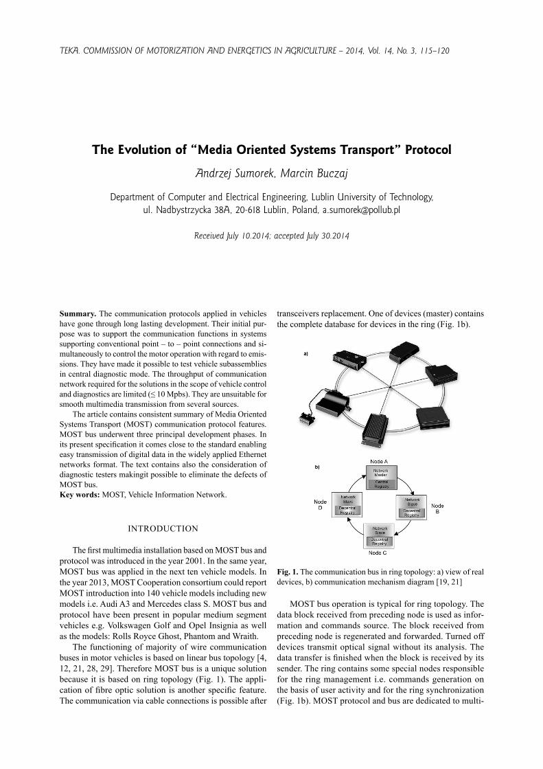
The functioning of majority of wire communication buses in motor vehicles is based on linear bus topology [4, 12, 21, 28, 29]. Therefore MOST bus is a unique solution because it is based on ring topology (Fig. 1). The appli-cation of fibre optic solution is another specific feature. The communication via cable connections is possible after
transceivers replacement. One of devices (master) contains the complete database for devices in the ring (Fig. 1b).
Fig. 1. The communication bus in ring topology: a) view of real devices, b) communication mechanism diagram [19, 21]
MOST bus operation is typical for ring topology. The data block received from preceding node is used as infor-mation and commands source. The block received from preceding node is regenerated and forwarded. Turned off devices transmit optical signal without its analysis. The data transfer is finished when the block is received by its sender. The ring contains some special nodes responsible for the ring management i.e. commands generation on the basis of user activity and for the ring synchronization (Fig. 1b). MOST protocol and bus are dedicated to multi-

116 ANDRZEJ SUMOREK, MARCIN BUCZAJ
media networks which are sometimes called Infotainment networks [1, 4, 5, 7, 26]. High throughput levels are re-quired for data stream in such networks. Despite MOST150 standard functioning since several years, this fact has been not mentioned in many publications. Most often the graph-ical presentations inform about the throughput of about 25 Mbps (Fig. 2) which is underestimated by three times. The throughput of 150 Mbps will be probably exceeded soon. The manufacturers of Plastic Optical Fibers (POF) indicate the throughputs of 500 Mbps along the section of 20 m or 170 Mbps along the section of 115 m [3, 6]. The transceiving equipment is prepared for operation with throughput of 5 Gbps [2, 13]. The current throughput is sufficient to use MOST as an element in the network sup-porting images received from security camera or from the games network [5, 18, 25].
Fig. 2. Lack of information on the throughput of MOST 150 bus in data summaries for communication protocols [19, 27]
The communications based on Function Blocks is the common feature of all MOST versions. Because MOST is a “new” communication method, it is possible to find references for its individual elements in layer type ISO-OSI model. Application layer commands are the key MOST Function Blocks as the standardized commands used to control the behaviour of devices installed in the ring and enabling the data transfer. It is assumed that each device installed in the ring and conforming with MOST specification will support the Function Block commands. Built-in support for Function Block is necessary in or-der to manage such devices. The functional addresses are assigned to the devices after their introduction into the ring. By means of said addresses the devices performing the role of controllers can read and declare the operation parameters of the devices performing the role of saves. The devices and accessible software can be divided into three (3) groups: Human Machine Interface – the software making it possible for the user to communicate with MOST bus devices, program user’s interface; Controllers – the devices functioning as the controllers for other devices (change of sound intensity, change of GPS system map on the screen), they manage the information about the Func-tion Block commands for controlled systems; Slaves – the actuators which do not contain any information about the system structure but respond to the Function Block com-
mands associated with them. Due to their passive role in the system, the slave devices can be added to and removed from the system without changing the configuration of the whole bus. The communication method based on Function Blocks is common for all versions of MOST protocol: 25, 50 and 150.
MOST25
The numbers contained in the MOST protocol version refer to approximated maximum communication speed ex-pressed in Mb s-1. Detailed data are contained in the Table 1.
The frame is the basic communication unit in the second layer of ISO-OSI communication model. In MOST25 the data are transformed in the form of blocks consisting of 16 frames. Each of 16 frames contains a part of message controlling the nodes. The control message is subdivided into the group of frames in order to reduce the utility data loading with control data.
The utility data within a single frame occur in the form of stream data (e.g. sound) transferred in synchronous mode and in the form of package data (e.g. GPS system). The length of parts of frame associated with synchronous and asynchronous may vary. This length is preliminary deter-mined by means of boundary descriptor. Therefore it is possible that package section does not exist or its length is equal to 9 four – bit words (Fig. 3). The initial bits of the preamble are used for slave nodes time synchronization. Two bits of control data are the part of larger message controlling the network and subdivided into frames in the whole block. The purpose of parity bit is to increase the transmission security [8, 23].
Fig. 3. MOST25 protocol frame [8, 9]
MOST50
As can be seen from the name of protocol in MOST50 version, its communication speed should be two times high-er than in case of MOST25. Except of increased speed of transceivers, the length and structure of the frame have been changed in physical layer. MOST50 frame is two times longer than in case of MOST25 and contains 128 bytes. MOST25 contains 4 bytes of control data arranged in two locations of the frame (Fig. 3). MOST50 contains 11 control bytes located in the header only on the beginning of the frame (Fig. 4).
It should be emphasized that the frame structure is more simple and more flexible in MOST50 version (control data

THE EVOLUTION OF “MEDIA ORIENTED SYSTEMS TRANSPORT” PROTOCOL 117
located in one header area). In case of lack of stream or package data it is possible to remove the area dedicated for such types of data.
MOST150
In case of the transmission in the framework of MOST150 protocol, it is required to increase the transceivers speed three times in comparison with MOST50 version. The frame is also three times longer and equals to 384 bytes. Its internal structure is not changed. The length of stream and package part can be adjusted in this part of data. The protocol is more efficient that in the case of version 50 because the area to be used for data has been increased from 117 to 372 bytes and accompanying control part has been increased from 11 to 12 bytes only [9, 23].
Fig. 5. MOST150 protocol frame [9]
From the structures of MOST25, 50 and 150 frames illustrated in Figures 3-5 it appears that there are no key changes introduced in MOST150. The previous synchronous communication and the support of new data called isochro-nous is actually possible in the stream communication part. An example for isochronous data is the data with sampling frequency different than basic frequency of the bus oper-ation. The synchronous mode is simulated regardless of asynchronous data transfer. There are three types of isoch-ronous channel support: Audio/Video packages streaming, discrete frames streaming and QoS (Quality of Service) isochronous mode.
Audio/Video packages streaming in isochronous mode consists in asynchronous data packages transfer depending on bus loading and on task load of MOST150 interface package support. Therefore the video support application is not required to provide band reservation or to establish the connection any more.
The discrete frames streaming is used when data sam-pling (e.g. audio) is other than bus speed. In such case audio data are transferred by the bus with sampling data in order to make it possible for the receiving node to transmit the data with sampling speed conforming with streaming speed.
QoS (Quality of Service) isochronous mode makes it possible to transmit the streaming data with specified qual-ity. In typical situation, an available band is shared by the applications. The quality assurance consists in reservation of required throughput for specified application [9, 23].
The asynchronous channel is often called package and Ethernet channel sharing the band with the synchronous channel. This channel makes it possible to send 93 four-bit words in a frame. MAMAC (MOST Asynchronous Medium Access Control) layer is responsible for TCP/IP protocol transmission via asynchronous channel in MOST25 and MOST50 versions. MOST150 contains MHP (MOST High Protocol) layer. Actually it is possible to address in asyn-chronous channel by means of 16-bit package addresses (conventional MOST addressing) and 48-bit Ethernet ad-dresses (addressing by means of MAC addresses) [9, 23].
Ta b l e 1 . Bandwidth of MOST 25, 50 and 150 frame [9]Parameter MOST25 MOST50 MOST150
Streaming dataMinimum bandwidth [Mbps] 8.48 0.38 0Maximum bandwidth [Mbps] 21.17 44.93 142.85Packet dataMinimum bandwidth [Mbps] 0 0 0Maximum bandwidth [Mbps] 10.84 44.54 142.85Control dataMinimum bandwidth [kbps] 405.84 448.00 512.00Maximum bandwidth [kbps] 405.84 810.62 1130.00
DIAGNOSTIC TOOLS
High throughput of MOST bus combined with fault tolerance is possible as a result of fibre optic transmission medium. The fibre optic communication makes the diagnos-tics and bus faults elimination more difficult [22]. However it is possible to gather information from typical diagnostic testers communicating with motor vehicle via standard OBD connection. It is impossible to establish any connection with the bus ring by means of typical multimeters. The transmit-ting – receiving diodes and bus socket are shown in Fig. 6.
The diagnostic workshops are unable to perform the repairs by means of actually possessed measuring and testing equipment. There are two methods used to detect a failure in fibre optic ring circuit. The first method is based on error message generated by master module in the bus. The master module contains the database for bus elements configura-tion. On the basis of times of response to the test signal introduced from the module into fibre optic conductor, the master module is able to determine, with high probability, the defective module or the fibre optic section with prob-lematic communication. In order to verify the diagnosis it is necessary to carry out the tests by means of special testers.
Fig. 4. MOST50 protocol frame [8, 9]

118 ANDRZEJ SUMOREK, MARCIN BUCZAJ
The tests consist in the replacement of defective module by the tester and in checking whether the ring is closed in this manner. Another method consists in fibre optic conductor continuity check performed by means of two testers, i.e. one tester used as the source of optical signal and another as the receiver thereof. Except stream travel continuity it also possible to measure light stream attenuation. An example of such tester for D2D bus is illustrated in Fig. 7. Fig. 7b illustrates how to connect two testers in order to check the fibre optic section.
Fig. 7. Diagnostics of optic ring on the example of D2B bus: a) tester; b) connection method [14]
The examples of motor vehicles with multimedia system based on MOST bus are the new models of BMW vehicles. The diagnostic system for such vehicle consists of a meas-uring head and software running on personal computer.
The measuring head is connected with an Ethernet interface on one end and to OBD diagnostics socket of the vehicle on another end. Therefore it is possible to gather standard information about vehicle condition or to reprogram the modules. Since several years the optical interface connector enabling direct tester connection to the optical ring is the mandatory equipment of such tester. Fig. 8 contains two photos of such devices – GT1 measuring head and OPS Di-CAN MOST tester. Thanks to comprehensive testers func-tions and accompanying software it is possible to read the error codes, to cancel the codes to carry out programming, data decoding, to locate the components and to display the connection diagrams.
Although the testers systems described above are suf-ficient for fails detection and elimination in workshops, their capabilities are rather limited in case of preparation of the new solutions of MOST bus. In case of nonstandard problems or in case of necessity to determine the technical boundaries of the project, it is necessary to use laboratory equipment dedicated to MOST protocol. Such specialized solutions are available for research tasks, e.g. „MOST150 Controller 6161” measuring card manufactured by GOE-PEL electronic (Fig. 9a). Using this card it is possible to perform typical bus tests i.e. ring continuity check and to configure MOST bus systems collaborating with CAN or LIN networks. Ready to use sets of tests are available for elements checking for their compliance with MOST pro-tocol requirements. An example of dialog window of such software delivered by LeCroy is illustrated in Fig. 9b [11, 24]. The physical tests are carried out by means of oscil-loscopes supplied by the same company. Similar solutions are proposed by Agilent. Its N6466A MOST Compliance
Fig. 6. Elements of fibre optic ring of MOST bus: a) transmitting – receiving diodes; b) fibre optic cables plugs; c) socket of MOST node [2, 8, 9, 10, 13]
Fig. 8. Testers heads dedicated for BMW vehicles: a) GT1; b) OPS [16, 20]

THE EVOLUTION OF “MEDIA ORIENTED SYSTEMS TRANSPORT” PROTOCOL 119
Application running on Infiniium oscilloscopes makes it possible to verify the compliance of hardware layer with requirements established by MOST standard.
CONCLUSIONS
The multimedia systems installed in vehicles have come a long way from the first lamp type receivers used in the thirties of the 20th century. The first fibre optic multimedia bus Domestic Digital Bus designed in early nineties of 20th century was the initial phase of MOST bus. The evolution of protocol used in Media Oriented Systems Transport bus makes it possible to make the following conclusions:– at the moment, the MOST bus is the fastest multimedia
bus dedicated to motor vehicles;– MOST protocol in MOST150 version is characterized
by high flexibility in the scope of band allocation for synchronous and asynchronous data;
– MOST150 version is characterized by facilitated trans-mission of data based on IP protocol and by introduced Quality of Service support;
– MOST bus makes it necessary to use specialized diag-nostic tools for elimination of errors in fibre optic ring;
– there are automated tools available for verification pro-cess automation for devices compliance with MOST standard;
– there is such a rich variety of currently available ele-ments, devices and descriptions that the special databas-es are created to contain the information about MOST bus elements [17].
REFERENCES
1. Alderisi G., Iannizzotto, G., Patti G., Bello, L.L., 2013: Prioritization-based Bandwidth Allocation for MOST networks. Proceedings of IEEE 18th Confer-ence on Emerging Technologies & Factory Automation (ETFA), ISBN: 978-1-4799-0862-2.
2. Angstenberger J., Tiederle V., 2013: Reliability Assess-ment of VCSEL Devices for 5 Gbit/s Data Transmission
in Automotive Environments, Elektronik – MOST 2013, 18-20.
3. Atef M., Swoboda R., Zimmermann H., 2011: 170 Mb/s multilevel transmission over 115 m standard step-index plastic optical fiber using an integrated opti-cal receiver, Optics Communications, 284, 191–194.
4. Bosch R. GmbH, 2008: Sieci wymiany danych w po-jazdach samochodowych, Warszawa, Wydawnictwa Komunikacji i Łączności (in Polish).
5. Cheng Y-H, Kuo W-K; Su S-L., 2010: An Android system design and implementation for Telematics ser-vices. Proceedings of IEEE International Conference on Intelligent Computing and Intelligent Systems (ICIS), vol. 2, ISBN: 978-1-4244-6582-8, 206–210.
6. Daum W. et al., 2001: POF – optische Polymerfasern für die Datenkommunikation, Springer Verlag.
7. Fijalkowski B.T., 2011: Automotive Mechatronics: Operational and Practical Issues, vol 1, Springer Sci-ence+Business Media B.V.
8. Grzemba A., 2008: MOST – The Automotive Multime-dia Network, Frazis Verlag GmbH.
9. Grzemba A., 2011: MOST – The Automotive Multi-media Network. From MOST25 to MOST 150, Frazis Verlag GmbH.
10. Hamamatsu Photonics K.K., 2013: Taking MOST to the Next Level, MOST Informative, 9, 11.
11. Hammerschmidt C., 2012: LeCroy rolls automotive data bus analyzer packages, EETimes Europe, www.electronics-eetimes.com/en/lecroy-rolls-automotive-da-ta-bus-analyzer-packages.html?cmp_id=7&news_id=222911110#, 01.02.2012.
12. Kaparuk J., 2010: Pokładowe systemy diagnostyczne OBD I EOBD oraz sieci transmisji danych, Poradnik Serwisowy, 4/2010, Warszawa, Instalator Polski, pp. 25-26 (in Polish).
13. Lichtenegger T., Schunk N., 2013: Optical TRX to Enable MOST Next Generation at 5 Gbit/s, Elektronik – MOST 2013, 24-27.
14. Mercedes Benz, 2004: Domestic Digital Bus (D2B). Technical training materials – 416 HO D2B (CooksonI), Mercedes-Benz USA.
Fig. 9. Advanced tools for analysis of MOST protocol MOST bus devices: a) measuring card; b) LeCroy testing package; c) os-cilloscope for LeCroy package [24]
120 ANDRZEJ SUMOREK, MARCIN BUCZAJ
15. Merkisz J., Mazurek S., 2007: Pokładowe systemy diagnostyczne pojazdów samochodowych, Warszawa, Wydawnictwa Komunikacji i Łączności (in Polish).
16. Moto Diagnostyka, Głowica – BMW OPS Optical Programming System, http://www.diagnostic.com.pl/pdf_datasheet.php?products_id=113, V 2011.
17. Sedlmair M.,, Bernhold C., Herrscher D., Boring S., Butz A., 2009: MostVis: An Interactive Visualization Supporting Automotive Engineers in MOST Catalog Ex-ploration, Proceedings of 13th International Conference Information Visualisation, ISBN: 978-0-7695-3733-7, 173-182.
18. Sirichaia P., Kaviyab S., Fujiic Y., Yupapind P.P., 2011: Smart Car with Security Camera for Road Acci-dence Monitoring, Procedia Engineering, 8, 308–312.
19. Steudten T., 2007: FlexRay: Flexibler Highspeed-Daten-bus im Auto. www.tecchannel.de /netzwerk/lan/1735234/flexray_flexibler_highspeed_datenbus_im_auto/index6.html (05.10.2007), IDG BUSINESS MEDIA GMBH München.
20. Sumorek A., 2011: Porównanie testerów uniwersalnych i dedykowanych w diagnozie pojazdu. Logistyka, 6, 3591-3600 (in Polish).
21. Sumorek A., 2011: Zróżnicowanie protokołów diag-nostycznych, sterujących i multimedialnych w pojaz-dach. Logistyka 3/2011, 2583-2592 (in Polish).
22. Sumorek A., Buczaj M., 2011: The problems in fibre optic communication in the communication systems of vehicles. TEKA. Commission of Motorization and Ener-getics in Agriculture, vol. XI, ISSN 1641-7739, 363-372.
23. Sumorek A., Buczaj M., 2012: New elements in vehi-cle communication Media Oriented Systems Transport protocol, TEKA. Commission of Motorization and En-ergetics in Agriculture, vol. 12, no 1, 275-279.
24. Teledyne LeCroy, 2011: WaveRunner 6 Zi Oscillo-scopes, teledynelecroy.com/ oscilloscope/oscillo-scopeseries.aspx?mseries=352&capid=102&mid=506, 02.02.2011.
25. Tonguz O. K., Boban M., 2010: Multiplayer games over Vehicular Ad Hoc Networks: A new application, Ad Hoc Networks 8, 531–543.
26. Wang C-C., Chen C-L, Sung G-N., Wang C-L., Juan C-Y., 2014: A FlexRay Transceiver Design with Bus Guardian for In-car Networking Systems Compliant with FlexRay Standard, Journal of Signal Processing Systems, vol. 74, 2, 221-233.
27. Wense H-Ch., 2000: Introduction to Local Interconnect Network, SAE Technical Paper, SAE 2000 World Con-gress, Munich, Germany, 6 March 2000.
28. Widerski T., 2005: Samochodowe sieci informatyczne. Poradnik serwisowy, 5/2005, Warszawa, Instalator Pol-ski, 28-36 (in Polish).
29. Zimmermann W., Schmidgall R., 2008: Magistrale danych w pojazdach. Protokoły i stan dardy, Warszawa, Wydawnictwa Komunikacji i Łączności (in Polish).
EWOLUCJA PROTOKOŁU „MEDIA ORIENTED SYSTEMS TRANSPORT”
Streszczenie. Protokoły komunikacyjne stosowane w pojazdach przeszły długą drogę rozwoju. Początkowo miały tylko obsługiwać komunikację w systemach zastępujących tradycyjne połączenia typu punkt-punkt. Jednocześnie kontrolowały pracę silnika pod kątem emisji zanieczyszczeń. Pozwalały i pozwalają na centralną diagnostykę podzespołów samochodowych. Rozwiązania sterowa-nia podzespołami pojazdu oraz diagnostyki wymagają niewielkich przepustowości sieci komunikacyjnej (≤ 10 Mpbs). Nie nadają się do płynnego przesyłania multimediów z kilku źródeł.Artykuł zawiera spójne zestawienie cech protokołu komunika-cyjnego Media Oriented Systems Transport (MOST). Magistrala MOST przeszła trzy główne etapy rozwoju. W aktualnej specy-fikacji zbliża się do standardu pozwalającego na łatwe przesyła-nie danych cyfrowych w postaci zgodnej ze szeroko stosowaną w sieci Ethernet. W tekście zamieszczono także rozważania na temat testerów diagnostycznych pozwalających na usuwanie usterek magistrali MOST.Słowa kluczowe: MOST, Vehicle Information Network.


![Object-oriented programming of adaptive finite element …jinnliu/proj/Device/1996OOP.pdf · Object-oriented programming of adaptive finite element and ... adaptive analysis ... [36]](https://img.pdfslide.us/doc/110x75/5b14d55b7f8b9af15d8c1bb0/object-oriented-programming-of-adaptive-finite-element-jinnliuprojdevice-.jpg)