Embed Size (px)
Citation preview

NOTICE
The quality of this microform is keaviiy dependent upon the quafity of the otiglnaf thesis submitted for microfilming. Every effort has been made to ensure the highest quality of repma'uctim possibie.
ff pages are missing, contact the university which granted the degree.
Some pages may have indistinct print especially if the originaI pages were typed with a poor typewriter ribbon or if the university sent u s an inferior photocopy.
Reproduction in iufI or in part of this microform is guverned by ithe Canadian Copyright Act, R S C . 1970, c. 3 0 and subsequent amendmen&.
La quaiite de cette microforme depend grandernent de la quaiit6 de !a these sournise au microfilmage. Nous avons tout fait pow assurer urre qualit6 superieure de reproduction.
S'il manque d e s pages, veuitlez comrnuniquer avec l'universith qui a confer8 Ie grade.
La qualite d'irnpression de certaines pages peut Iaisser a dhsirer, surtuut si les pages originafes ont 6te bactyfographi6es A lkaide d'un ruban use ou si f'universith nous a fait parvenir une photocopie de quafit6 inferieure,
La reproduction, m h e partielfe, de ceffe microfurme es t soumise a fa toi canabienne sur fe droit ri'aufeu~~ SRC f 97Q c. C-30: et ses amendements subsequents.

-1. THE Sff SKBLIIT TED IS PARTIAL FULFILLMEST
OF THE REQUIREVESTS FOR THE DEGREE O F
~ ~ S T E R OF -APPLIED SCIESCE
in ;be Schcol of
Engineering Science
The author has granted an Irrevocable non-exclusive licence attowing the Nationat Library of Canada to reproduce, b a n , distribute or setf copies of his/her thesis by any means and in any form or format, making this thesis avaitabte to interested persons.
L'aaateur a accord& une licence irrevocable e t non exclusive permettant a la BibiiothBque nationale du Canada de reproduire, prgter, distribuer ou -
vendre des copies be sa t h h e be quelque manilitre e t sous qiielqtfe fsrme que ce soit pour rnet?re d e s exempfaires be cetie these a la disposition des personnes intkressees.
The author retains ownership of i'auteur conserve fa propriete du %he copyright in hisfher thesis- droit d'auteur qui protege sa Neither the thesis nor substantial these. Ni la th&e ni des extraits extracts from it may be printed or substantiels icie celle-ci ne sthewise reproduced withotit doivent &$re imprimes ou hisfher permission, autrement reproduits s a n s son -
autorisation.
APPROVAL
Name: Tony Chan
Degree: Master of Applied Science
Title of thesis: The Error Performance Evaluation of Coded Sys-
tems in Radio Fading Channels
Examining Committee: Dr. John Jones, Chairman
Dr. Paul Wo Senior Super7;isor
Dr. Jacques tiaisey Supervisor
Dr. James Cavers Examiner
Date Approved: March 31, 1993
I hereby p t to Simon Fmsa University the right to lend my thesis, project or extended essay
(fie title of which is show2 k b v j to users of the Simon Fraser University Libraq, and to make
pafiid or ,&ngle copies only for such users or in response to a request from the library of any
other university, or otfia educational institutbn, on its own behdf or for one of its users. I
fu&er a p e that permission for multiple copying of this work for scholarly purposes mEy be
granted be me or the Dean of Graduate Studies. It is understood that copying or publication of
this work for financia! g& shd1 not be allowed without my mitten permission.
"The Error Performance Evafuahon of Coded System in Mobile Radio Fading Channel"
Author:
The mobile radio channel is a frequency selective fading channel which increases the
bit error rate of data +,ransmission when compared to the frequency non-selective
(or flat) fading channel. The emerging Korth American digital cellular system uses
convolutional code in conjunction with 2-QPSK to improve the data transmission
quality.
In this thesis, we attempt to improve the error performance of the existing coding
system used in cellular applications. ?Te will evaluate the error performance of two
coded systems: trellis coded modulation (TCM), and convolutional codes. Specifi-
cally, we will investigate the feasibiEty of using TCM to replace convolutiona1 codes
in celfular applications.
We first investigated the error performance of uncoded QPSK transmitted over
a frequency selective fading channel and this channel is modelled as a 2-ray channel
with independent Rayleigh flat fd ing in each ray. It was found +hat the relative delay
between the two arrival rays introduces a diversity effect which helps to improve the -
error performance I ~ I ~ I I compared to the Bat fading channei. hen, we designed
and stadied the emor perfom-mce of coherent trellis-coded I-nPSK modulations in 4 3
the additi.r-e white Gaussian noise (AWGS) and the Rqleigh flat fading channels.
The basic idea is to use multiple trellis coded modulations. Several good codes are
designed with thraughpur eqaal ro 1.5 birs/synbof and 1 bit/s.=mboi. One of the codes
bas a 44. dB coding gain compared to ancoded QPSK in ar! .?itVGS cfrarmcl while
another one p r o ~ r d e a 5% d e r dirersizy eifect in a flat fading cilaniiei. [Ye have
also compwed the enor performance of the trellis codes with conventional systems
that rise c o n v o f ~ t l o d code ir?, crtnjuodon with 2-QPSK rnoddation. We found that
trelPis codes pedora at %east as tsw4 as convolutional codes. In some cases, the coding
gain can be as !xge zs 2ddE. Einzlls we combined the results from the two previous
studies and invetigzied the enor frerformacce of coded systems in frcyuenty selective
fading channels. For an sncoded ~vstem. it, was found that frequency selective fading
introduces a diwfsiry e-ifect which improves the error perfornrance. However, this is
not true for coded sptems. For both trellis codes and co~xofutional codes, the best
performance belongs to the frequency nc 3 selective fading channeI. Nevertheless,
trellis codes once again perform at least as well as convolutionaf codes in frequency
selective fading cha~rsels.
ACKNOWLEDGMENTS & * d*,,
I would like to express my sincere appreciation to Dr. Paul Ho for providing the
subject of this thesis aod the pidance throughout the course of this research. I
::-oufd also like to thank Dr. P.J.McLane for the many insightful discussions during
the course of the thesis.
Financial support from the Canadian hstitute of Te1ecommunicaf;ion Research (CITR),
titrough Dr. P.J.McLax of Qaen's University, is gratefully acknowledged.
Finally, special thaoks tto my falllily and friends for their encouragement during the
preparation of the thesis.
CONTE
ABSTRACT . . . . . . . . . . . . . . . . . . . . . . . . . . . . . . . . . . . .
ACKKOWLEDGM ESTS . . . . . . . . . . . . . . . . . . . . . . . . . . . . .
LIST OF FIGURES . . . . . . . . . . . . . . . . . . . . . . . . . . . . . . . .
LIST OF TABLES . . . . . . . . . . . . . . . . . . . . . . . . . . . . . . . . .
I Introduction . . . . . . . . . . . . . . . . . . . . . . . . . . . . . . . . . . .
1.1 Backgrouod and Literature Review . . . . . . . . . . . . . . . . . . .
1.1.1 Frequency Selective Fading Channel . . . . . . . . . . . . . . .
1.1.2 Treilis Coded Modulation . . . . . . . . . . . . . . . . . . . .
1.1.3 Coded Systems Operating in a Frequency Selective Fading Chan- nel . . . . . . . . . . . . . . . . . . . . . . . . . . . . . . . . .
1.2 Contributions of the Thesis . . . . . . . . . . . . . . . . . . . . . . .
1.3 Thesis Outfioe . . . . . . . . . . . . . . . . . . . . . . . . . . . . . . .
2 The Error Performance of Uacoded QPSK . . . . . . . . . . . . . . . . . .
2.i System Overview . . . . . . . . . . . . . . . . . . . . . . . . . . . . .
2.2 Uncoded QPSK with Perfect Channel State Information . . . . . . .
2.2.1 Systerrr %ode1 . . . . . . . . . . . . . . . . . . . . . . . . . . .
2.2.2 Error Analysis . . . . . . . . . . . . . . . . . . . . . . . . . . .
. . . . . . . . . . . . . . . . . . . . 2.2.3 Example: Two-Ray Model
v
xi
xii
1
3
3
6
. . . . . . . . . . . . . . . . . . . . . . . . 2.2.4 NumericalResults
. . . . . . . . . . . . . . . . . . 2.3 Imperfect Channel State Information
. . . . . . . . . . . . . . . . . . . . . . . . . . . 2.3.1 Error Anak~sis
. . . . . . . . . . . . . . . . . . . . . . . . 2.3.2 3umerizal Results
. . . . . . . . . . . . . . . . . . . . . . . 2.4 The effect of Pulse Shaping
. . . . . . . . . . . . . . . . . . . . . 2.4.1 The Raised Cosine Pulse
. . . . . . . . . . . . . . . . . . . . . . . . 2.4.2 Simulation Model
. . . . . . . . . . . . . . . . . . . . . . . . 2.4.3 Numerical Results
. . . . . . . . . . . . . . . . . . . . . . . . . . . . . . . . . 2.5 Summary
. . . . . . . . . . . . . . . . . . . . . . . . . . . 3 Trellis-Coded Modulation
. . . . . . . . . . . . . . . . . . . . . . . . . . 3.1 Trellis-Coded 2-QPSK
. . . . . . . . . . . . . . . . . . . . . . . . . . . . . 3.2 Design Procedure
. . . . . . . . . . . . . . . . . . . . . . . . . 3.2.1 Rate 3/2 Codes
. . . . . . . . . . . . . . . . . . . . 3.2.2 Rate 3/3 and 212 Codes
. . . . . . . . . . . . . . . . . . . . . . . . . . . . 3.3 Simulation Results
. . . . . . . . . . . . . . . . . 3.4 Comparisons with Convolutional Codes
3.5 64 State. Trellis Codes and Comparison with the IS44 Convolutional . . . . . . . . . . . . . . . . . . . . . . . . . . . . . . . . . . . . Code
. . . . . . . . . . . . . . . . . . . . . . . . . . . . . . . . . 3.6 Summary
4 Performacce of Coded Systems in Selective Fading Channels . . . . . . . .
. . . . . . . . . . . . . . . . . . . . . 4.1 Derivahn of the Decoding Metric
. . . . . . . . . . . . . . . . . . . . . . . . . . . . 4.2 Simulation Results
4.3 Summary . . . . . . . . . . . . . . . . . . . . . . . . . . . . . . . . .
. . . . . . . . . . . . . . . . . . . . . . . . . . . . . . . . . . . 5 Conclusions
5.1 Conc!usions . . . . . . . . . . . . . . . . . . . . . . . . . . . . . . . . LO1
5.2 Suggestions for Further Research . . . . . . . . . . . . . . . . . . . . 103
A Effect of the Pox-er Spflt Rztio . . . . . . . . . . . . . . . . . . . . . . . . 1%
B Trellis structure of the 8 statet rate 3 f 2 code . . . . . . . . . . . . . . . . . lllS
C Trellis structures crf 64 state codes . . . . . . . . . . . . . . . . . . . . . . . 111
REFERENCES . . . . . . . . . . . . . . . . . . . . . . . . . . . . . . . . . . . 128
... f i i f
T OF FIGU
2.1 The Block Diagram of a Communication System . . .. . . . . . . . . .
X n A "t 2.3 The rnatcUcu m:er rrespo~se . . . . . . . . . . . . . . . . . . . . - . .
2.4 TreiGs Biagrm ;or the t'iterbi Decoding of QPSK in a 2 - i q ~ Channel
2.5 The Approximated Bit Ezor Probability of QPSK \~itr! El = E2 . 2.6 The Approximated 131:. Error Probability of QPSK it-ith El = 16E2 .
2.1 The Xpprfrximsted Biz Error Probability of QPSK at E = 20 d B and with power sp& ratio as a parzmeter . . . . . . . . . . . . . . . . . .
2.8 The Xpprftxiaatd Bit Error Probability of QPSK at E = -10 dB and with power spEi:; ratio as a paale ter . . . . . . . . . . . . . . . . . .
2.9 The Simdzkd Bit Ermr Probability of QPSK with El = E2 . . . . . 2-10 The Sina,z.fated Bi: Error Probability of QPSK at E = 20 dB and ~ 5 t h
power s p k ratio as a parameter . . . . . . . . . . . . . . . . . . . . . 2.31 The Xppraximaied Bir Error P~rsfjability of QPSK is-i t t El = E2 . .
2.22 The Approximated Bit Error Probability of QPSK with El = 16E2 . 2. f 3 The .4pproximated Bit Error Probability of QPSK at E = 20 dB . .
'3 -. 1-2 The Approximated Bit Error Pmbability of QPSK at E = 40 dB and it-.;& p';-"r s&r fat,io as 2 p=~=eter . . . . . . . . . . . . . . . . . .
2-16 Tire Sirnuked Bit Error Probability of QPSK at E = 20 dB and with . . . . . . . . . . . . . . . . . . . . . power s p 5 ~ r a i o zs a parameter 46
2.18 The Treliis Dizgram for the 1-iterbi Equalizer with Prilsc Shaping. (0: f : 2, 3; are ::he _t'uz&ep .%sso&tpd v;itfi Q f ) S f < Sig;jais S h m n
. . . . . . . . . . . . . . . . . . . . . . . . . . . . . . . in Figue2.4. 53
2.19 The Simulzted Bit Error PtobabiIit:; of QPSK with El = E2 a d Pulse - - . . . . . . . . . . . . . . . . . . . . . . . . . . . . . . . . . . Shaping 22
- 2.20 The Sirnuiated Bit Lrror Probability of QPSK with Pulse Shaping at
E = 25 dB and with the poil:er sp?it ratio as a parararler . . . . . . . 56
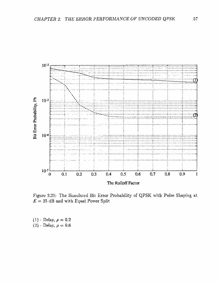
2.21 The Sinaiazd Bit Ermr P ~ o b ~ b i l i t ~ of QPSK with Pulse Shapizlg at E = 25 dB a d xi& Equal Po-xrr Split . . . . . . . . . . . . . . . . . 37
3.1 The %-QPSft= Siwd Gnnstefiztrion. . . . . . . . . . . . . . . . . . . . 6%
3.2 X 4 state, rate 3 j2 code ~ 5 t h 1 gara!lel transitiorxs betiwen pairs of states 65
3.3 An 8 sraee. rzte 3T2 code with 2parallel transitions bctwcn pairs of . . . . . . . . . . . . . . . . . . . . . . . . . . . . . . . . . . . states 65
3.4 Set partitioning ai the $-QPSK signal set over a 3 symboi inrervai . GG
3.6 The Error Perfomace of Differeat Codes in the AtYGS Char~iiel . . 7.5
3.1 The Error Perforname of DiEerent Codes in the Flat Fading Channel 76
3.8 A Coqmrison of the Bit Error 23E.ribrrnance of Coded 9yster:ts :.i.itfi a . . . . . . . . . . . . . . . . . . . . . . throu&prtt of 1.5 bi~sJsymboH 80
3.10 The Error Perfurmznce ci 54 state Codes in the Rityicigh I-*;:ding Chanrtel 83
The Error Pedwmmce of the 16 State, Rate 2/2 Code in a Frequency Selective Fading Channel Usiog a Rectangular Pulse and with Delay
. . . . . . . . . . . . . . . . . . . . . . . . . . . . . . as a Parameter
The Error Performance ctf 16 State, Rate 2f2 Code in a Frequency Sefectir-e Fading Channel Csing Rectangular Pulse and with the Power
. . . . . . . . . . . Split h r i c as a Pararzeier. The Bit SSR is 8 dB
The Error Penir,mmce of 16 state; rate 212 Code in a F'requency Se- lective Fading Channel Using Raised Cosine Pulse and with a Rolloff Factor c+f 0.35 . . . . . . . . . . . . . . . . . . . . . . . . . . . . . . .
The Error Perfo-masce of the 16 State, Rate 212 Code in a Frequency Selective Fading GSLmrrel TIsing a Raised Cosine Pulse with a Rolloff Factor of 0.35 and i ~ i t h itbe Power Split Ratio as a Parameter. The Bit
. . . . . . . . . . . . . . . . . . . . . . . . . . . . . . . . SNR is &3 dB
The Error Perictmance Comparison between the 16 State, Rate 212 Trellis Code and the 8 State: Rate 1 f2 Convolutional Code. Both use the Rectangdaz Pulse . . . . . . . . . . . . . . . . . . . . . . . . . .
The Error Performance Comparison between the 16 State, Rate 212 Trellis Code and the 16 State, Rate 1/2 Convolutio~al Code using a Raised Cosioe Pnise with a Roiloif Factor of 0.35 . . . . . . . . . . .
The Error Pericfmance of 64 state, rate 2/2 Code in the 2-ray Fre- quency Selective Fading Channel Gsing a Raised Cosine Puke with a Rolloff Factor of 0.35 . . . . . . . . . . . . . . . . . . . . . . . . . . .
The E m f Performance Cornparison between the 64 state, rate 212 Code and the 32 state, rate 1/2 convolutional code in the h a y Fre- quency Seiectiw Fading Chamef Esing a Raised Cosine Pulse with a R d o E Factor of 0.35 . . . . . . . . . . . . . . . . . . . . . . . . . .
F TABLE
2.1 The irrtersydml icierference Magnitude at different ticlays for the raised cosine pulse of a rctffof factor of 0.35 . . . . . . . . . . . . . . . 52
3.1 A P e d o r ~ a x e Summary for Digereat T d i s Codes . . . . . . . . . . 72
mm CHAP IBR 1
Introduction
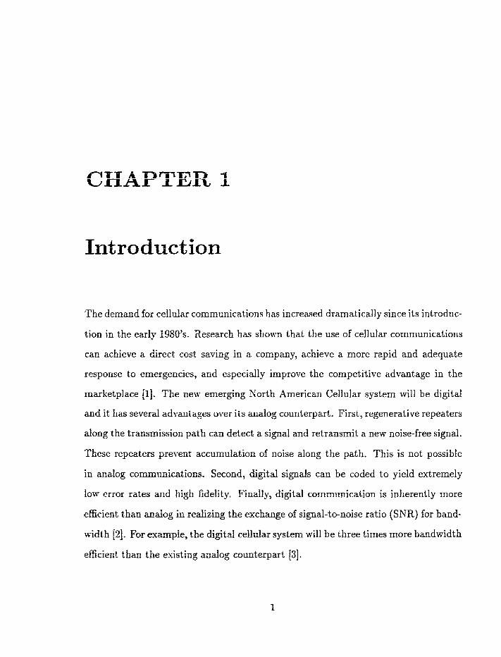
The demand for celldar coamunications has increased dramatically since its introduc-
tion in the early 1980's. Iiesearch has shown that the use of cellular communications
can achieve a direct cost saving in a company, achieve a more rapid and adequate
response to emergencies, and especially improve the competitive advantage in the
marketplace [I]. The nely emerging Sorth American Cellular system will be digital
and it has several ad:-mtages over its analog counterpart. First, regenerative repeaters
dong the transmission path can detect a signal and retransmit a new noise-free signal.
These repeaters prevent accumulation of noise along the path. This is not possible
in analog communications, Second, digital signals can be coded to yield extremely
iort- error rates and high fidelity Finally, digitd communication is inherently more
efficient than anahg in realizing the exchange of signal-to-noise ratio (SNR) for band-
wi&h 12). For exampk, the digital cellular system will be three times more bandwidth
efficient than the existing analog counterpart [33.
Digital transmission over cellular communication channels has become an impor-
tant research area and a major consideration is the bit error performance of the
communication system under different channel conditions. In mobile radio systems,
a received signal is normally modified by its environment such as the Doppler fre-
quency caused by the motion of the vehicle and the presence of multiple paths. Such
an environment leads to frequency selective fading which can cause degradation of
the bit error rate (compared to its non-selective fading counterpart). Frequerlcy se-
lective fading means that different frequency components of the transmitted signal
nill be subjected to different fading gains, and these fading gains can be correlated.
One method of improving the error performance in such an environment is to employ
combined equalization and channel coding techniques.
This brings us t o the central theme of the thesis: to study the error performance
of various combined equalization and channel coding techniques operating in the fre-
quency selective fa&g environment. Specifically, the frequency selective fading chan-
nel will be modelled as a %ray channel with independent Rayleigh fading in each ray.
In addition to using conventional channel coding techniques, we will design trellis
coded modulation (TCX'I) schemes that are matched to the digital cellular system's
modulation format, i.e. f-shifted QPSK. Our ultimate goal is to see if these coded
modulation schemes are superior to convolutional codes in the cellular application in
the sense of providing better bandwidth efficiency. In all our studies, perfect channel
impulse respame estimation is assumed. A soft decision metric that takes into ac-
courtt interleaving and the time varying nature of the channel impulse response is also
derive& This decoding metric is applied to both the convaiutional codes specified in
the digital celldar standard and the TCM schemes we designed.
1.1 Background and Literature Review
This thesis is divided into three parts. First, we investigate, via analytical means, the
error performance of uncoded systems transmitted over a frequency selective fading
channel. This study is relatively simple but it enables us to understand the behaviour
of digital modufations operating in the frequency selective fading environment. Then
in the second part, we design new TCM schemes which are compatible with the -
QPSK format. The code design procedure assumes a flat (i.e. non-frequency selec-
tive) fading environment. This means that the design criterion is the free Hamming
distance [12] (at the symbol level) of the coded modulation scheme. The objective
here is to come up with new TCM schemes that are more bandwidth efficient and/or
power efficient than the convolutional code (in conjunction with the $-QPSK scheme)
specified in the digital cefldar standard. Finally, we will investigate the error per-
formance of our TCM schemes, as welf as that of convolutional codes with the same
throughput and compiexity, in the frequency selective fading environment. Below is
a literature review for each of these parts of the thesis.
1.1.1 Frequency Selective Fading Channel
During the last few years, a number of studies have been carried out to investigate the
error performaace of digital communication systems operating in frequency selective
fading channels. These studies can be classified into 3 categories: the characteristics of
the channel, the error performance of coherent detection and the error performance of
differential detection. An experiment ming a multi-tone technique has been designed
to determine the degree of frequency selectivity of a mobile radio channel [4]. The

multi-tone method basically transmits a group of closely spaced tones to a mobile
receiving system. By the measuremerat of each tone and comparison of the relative
effects of the mobile channel on each of these tones, it is possible to determine the
response of the frequency selective fading channel. A measure of the selectivity is
the correlation between two tones; for example, a perfect correlation corresponds to
the absence of frequency selectivity. From the results of the experiment, the most
disturbing factors in a selective fading channel are hills and the number of reflectors
present. For a small channel bandwidth, a large number of reflectors does not seem
to destroy the signal from the point of view of frequency selectivity.
Digital transmission over a mobile frequency selective fading channel can be de-
tected either coherently or differentially. In the case of coherent, detection, a theoret-
ical comparison of the average bit error rates of four digital modulation techniques
subjected to Rayleigh distributed two-ray multipath fading has been performed in
151-161. The four digital modulation techniques are BPSK (binary phase-shift keying),
QPSK (quadxture phase-shift keying), OQPSK (offset phase-shift keying) and MSK
(minimum phase shift keying). Results show that BPSK is the most tolerant to multi-
path distortion among the four modulation techniques. This arises from the fact that
BPSK suffers from no cross channel interference between the in-phase and quadra-
ture components, while the other three modulations suffer from severe cross channel
interference, in addition to the intersymbol interference from adjacent data symbols.
However, BPSK has a poor spectral efficiency. In 171, Mazo considered the case of
coherent detection of BPSK and 4QAM (4 level quadrature amplitude modulation)
in a 2-ray itayieigb fading channel. Specifically, he derived an exact matched filter
bound for the error probability.
In the case of differential coherent PSK (DPSK), the effect of baseband pulse shap-
ing on the error performance in a Rayleigh fading channel is studied in [8],[9]. The
authors showed that the performance of DPSK over a frequency selective Ftayleigh
fading channel can be closely approximated by parameters which are obtained from
the measurements of the channel. An example of such a parameter is the normal-
ized root mean squared multipath spread. An approximation technique, based on
these parameters, was developed for obtaining performance bound for DPSK over
frequency selective fading channels. This approximation can dso be applied to the
more general frequeacy selective Rician fading channels. In [lo] and ill], the bit error
rate performance of % - DQPSK modems in the cellular mobile channel was derived
and analyzed. The chamel is modelled as a frequency selective fast Rayleigh fading
channel corrupted by additive white Gaussian noise (AWGN) and co-channel inter-
ference (CCI). The probability density function of the phase difference between two
consecutive symbols of a M-ary DPSK signal is first derived. Based on the probability
density function, the bit error rate of ;-DQPSK is derived in closed form and calcu-
Iated directly. The numerical results show that for 2 - DQPSK, the bit error rate is
?ominattd by the CCI. This analysis in j lD] can be extended to investigate the error
performiznce of a frequency selective fading channel with multiple CCI.
All the studies mentioned above only considered uncoded modulations. As men-
tioned earlier, coding (together 5i th interleaving and equalization), is a necessity for
good error performance in the frequency selective fading envi~onment. Below is a
literature review on coded modulation schemes.
Io the past decade: one of the most poplar coding techniques is TCM, which vas first
ictroduced by t-~gerboeck jf2j. TC3f is known for its abiliti. to achieve a significant
coding gain i ~ i i h ~ ~ i sacriEcing data rate or requiring extra bandxidth. Tile n~ain
idea beffind 'TCx n:+ -=o- Gcm&& expansion to FrGvi& r ~ u l ; ~ a l ; C 5 ' for tocfiiig,
and to design codiag mci signd-mapping functions jointly so as to directly masirriizr
the minimum EncIidean distance (or free hamming distance) bet~s?;eert coded signal
sqtiences. The x d t i ~ g Eiiclirlean distance of the coded sequence significantly ex-
ceeds the mini=== 2 i t s n c ~ b e ~ r ~ e e ~ ancoded modufation signals at the same infor-
mation ratet fra~~dwi&%, a d sfgziai paiyer. For example, consider the result in (121
where Ungerbcteck compand his &sratx, 8-PSK Trellis code with the uncoded 4PSK
scheme. Both systems t rwmit tm idormittion bits per modulation interval. How-
ever, the free hamming &:lsta~ce for w m d e d 4-PSK is only 1.414 whereas the free
Emming distance for Trellis-coded &state, 8PSK is 2,141. Such an improvement in
the ffee H m b g &srmce restt4ts in a coding gain of 3.6 dB over uncoded 4-PSfi in
ssn additive white Ga*;ssijl;lti: coke tbiznnei.

fn 1988, Wilson 1151 introduced a new TCM technique that was based on Unger-
boeck's 8 state, &PSK treflis code. Wilson assumed that 8-PSK modulation is used
twice per treflis interval (forming a Wary set), but that this se5s coded with a 5/6
trellis code. Thus, the spectral efficiency (5 bits/2 symbol) is better than the &PSK
(2 bits/symbol) trellis code. Wilson showed that his 8 state code provides a 6.2 dB
gain on the Gaussian noise channel over uncoded &PSK, while sacrificing only 16%
in spectral efficiency. This modulation scheme of Wilson was then generalized by
Divsalar and Simon to create a technique called multiple trellis coded modulation
(MTCM). Later on, Divsalar and Simon considered the performance of multiple trel-
lis codes in a Ricim fading environment f16-181 and showed that the design of TCM
is guided by factors [in particular, the length of the shortest error event path and
the product of branch distances along that path) other than the squared Euclidean
distance when used in a Rician fading channel with interleaving/deinterleaving [17].
The common drawback in the above studies was that all the results were obtained via
computer simulation. Although simulation is capable of reflecting the actual system
performance, it is a time-consuming process. In addition, simulation studies cannot
provide much insight into the understanding of the behaviour of the system.
The first analytical result on trellis coded MPSK modulation transmitted over
a fading channel was reported by Divsalar and Simon [19], where they applied the
Chernoff bound technique to obtain an upper bound on the pairwise error probability.
By making use of the pairwke error prolxbility bound and the transfer function of
the pair-state transition diagram, an upper bound of the average bit error probabil-
ity was obtained. Later on, Divsalaf and Simon [20] used a similar technique and
exteaded their analysis to indude trellis-coded multilevel diiferential phase shift key-
ing (MDPSK), Howxer, the upper bounds obtained were too loose over the normal
CHAPTER 1. INTRODUCTION 8
range of signal to noise ratios of interest. Besides, the pair-state transition diagranl
approach may be a tedious task when the number of states in the trellis diagram
becomes large. By using the characteristic function and the numerical Gauss-Konrod
integration rule, McKay et a1 1211 were able to evaluate an exact pairwise error event
probability for TChf in Rayleigh and Rician fading channels. Although his results
were satisfactory, the numerical evaluation of this upper bound is quite complicated.
By employing the characteristic function and the residue theorem, Cavers and Ho
[22] obtained an exact and easily computed expression for the pairwise error event
probability of TCM operating in Rayleigh fading channels. This expression is quite
general and includes not only trellis coded MPSK, but also trellis-coded quadrature
amplitude modulation (QAM) with perfect channel state information (CSI), differen-
tial detection, or pilot tones. Acclirate average bit error probabilities were obtained
by considering only a small set of short error events.
All the studies cited in this subsection on TCM consider only the additive white
Gaussian noise (AWGN) channel or the Rayleigh flat fading channel. There are rela-
tively few studies of coded systems and their performance in frequency selective fading
channels. A survey of studies in this latter category is given in the next subsection.
1,1.3 Coded Systems Operating . , a Frequency Selective
Fading Channel
One of the inter2st.s in frequency selective fading channels is the decoding metric used
for coded systems. it is well known that maximum-iikebfiood sequence estimation
(MLSE) [23] is the optimal decoder for coded systems operating in a frequency se-
lective fading channel. However, the computational compfexity of MLSE increases
exponentially with the channel memory. Moreover, it is complicated by the presence
of interleaving and de-interleaving that. is usually required for good performance in
coded systems. Consequentiy, a number of studies have been carried out to find other
decoding metrics which can reduce the decoding complexity and still retain the same
bit error rate a% a given signal-to-noise ratio. In [24], a sub-optimum variant of the
optimum soft decisim equalizer is presented, namely the soft decision Viterbi equal-
izer (SDVE), which is similar in structure and in implementation effort to the classical
zL-state Viterbi equalizer with L bit path history. Moreover, the complexity of
SD\IE is less tha;: that of the soft-decision output Viterbi a!goritfm (SOYA) proposed
by Hagenauer f26f.
In f27], Haeher, starting from the optimum structure, derived a reduced com-
plexity receiver. Under the constraint of similar complexity, Boeher showed that the
modified symbol-by-symbol estimator outperforms the sequence estimator when the
signal space is nonbinary. He considered both trellis-coded 8 PSK [12] and uncoded
4PSK (as the reference system) and shox-ed that the simplified version of the symbol-
by-symbol algorithm is more powerful than the sequence estimator.
Other studies on reduced comp!eiit__s. sequence estimation that can be applied to
the frequency sdedive fading channel icclude the one reported in E28f. There the
reduced state sequence estirnaror (=SE) uses a conventional Viterbi algorithm with
decision feedback to search for a reduced-state "subset trellis" which is constructed
wing set; partitiof;ng p~heipks [f2]. T o e set partitioning pfincipies systematicdy
reduce the cornpiexiif: of the seqrtence esiimator, due to the length of the channel

memory and the size of the signal set. An error probability analysis sllows that a
good performancejcomp1exity tradeoff c m be obtained. Other reduced compirsity
equafization techxiiques include the 11-algori~hrn of Anderson and IIohan f29f and the
T-afgoritftrn of Sirnmclns 1301.
*- En this thesis7 we w!f d e r k a decodizig rnetric similar to that ir: [24] to i::~ts- --
tigate the error performance of our new TChf schemes in the frequency selective
fading channels. X suboptimal version of this decoding metric isill also be presented.
This suboptima! mer;ri-.,c dl intmfve the truncation of the channel impulse responsc
estimate, as well as the removal of the exponential operator in the metric given ir t
E24j -
1.2 Contributions of the Thesis
The major contributions of this thesis cur be sunmarized a f'tlows:
1. An investigation of the error ped~rmance of uncoded sptems transmitted ovcr
a frequency selective RayTeigh fading channel. We found that the channel provides
an implicit diversity effect that hdps to improve the error performance over that of a
Bat ;'ding channel.
2. The d e s i s af new TCf f schemes that are compatible $vit h the S-QPSK mod-
ulation format chasen far digital cellular application. It was found that these rlcw
methods perform at leas as well as c~nvo~utionaf codes in the fiat fading environ-
ment, In same cases, our ex TCM schemes are 1 to 2 dB more energy efficient than
con~wTrrtiond codes with similar iirrctugbpnt and c;ornplexitt;.
3. The evaltrztion ui rhe error performance of coded systems operating in frequency
seiective fading channels. The decoding metric for coded systems is derived. As in
the Bat fading cha~ne!, it was found that trellis codes still perform at least; as well as
con~wlutional codes, and in some cases, significantly better. It was also found that
the frequency selective fading channel does not provide s diversity effect in coded
systems.
1.3 Thesis Outfine
Chapter 2 desc-rIbe the system model used in this study itnd azlalyzec the error per-
formance of uncocfed QPSK in the frequency selective fading channel; both analytical
and simulation restrits dl 'be gke=. In addition, we have also investigated the effects
of pulse shaping on the error performance. Chapter 3 presems a design procedure for
trellis-coded 2-QPSK schemes a d compares the error performance of the designed
codes with conr.entio~aI coding systems using convolutionai codes. The results given
in chapter 3 apply u d y to the Bat fading channel. In Chapter 4, we evaluate the
error perfommice of coded sys~ems in the frequency selectiw fading cirannel. We will
also derive in xhis chapter the decoding metric used in the frequency selective fading
channel. Simrrfaiion resdts will be presented. Finally, conclusions of this study will
be given in Chapter 5.
The Error Performance of
Uncoded QPSK
fn mobile radio comiffunaicztions: a signal seceix-ed by a vehicle is significantly ~rlodified
by its environment. First, the rnotior! of the vehicle causes a Doppler effect tl lat shifts
its frequency. Seconrlli., mzq- rays due to reflection and diifraction of the signal on
various objects s- togerher to form ac interference pattern. As the vehicle moves
throrrgh this pattern, the received sipah will suffer from frequency selective fading.
Frequency selectivity egects are important: especially in digital cornmunicatior~s where
it leads to ictersq;mbai interkrecce tirat can cause degradation iii bit error rate [31].
state informatio~ QCSf). Afi exact expression for the pairwise error probability of the
deader wilf be pre~ite2. As the reader will discover, the analysis given in this chap-
ter is a more genera1 version of that; given in [TI. Although conventional tlncoded
QPSK is being consideredt the analq-tical and numerical results presented will dso
hold for f -QPSK.
In addition to the study n-ith perfect CSI , we will also consider the effect of im-
perfect CSI. hforwer? the effect of pufse shaping on the error performance will also
be studied.
This chapter is organized zs foffoiiis. Section 2.1 presents the general model of our
communication system. Section 2.2 analyzes the bit error probability of the uncoded
QPSK modulation using a rectangular pulse transmitted over a %ray frequency selec-
tive Rayleigh fading charnel with perfect channel state information- Both analytical
and simulation r a d t s are presented. In Section 2.3, the case of imperfect channel
state information will be investigated and once again the baseband pulse has a rect-
angular shape. Both analytical and simulation results will be shown. Section 2.4
discusses the effects of pdse shaping. Due to the complexity of the system model,
theoretical analysis is very hard to perform and hence only simulation results will be
gisen. Finafly, a summary of the chapter is given in Section 2.5.
2.1 System Overview
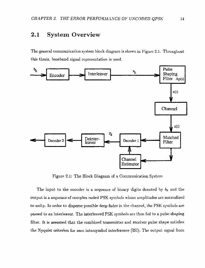
The general communication system block diagram is shown in Figure 2.1. Throughout
this thesis, baseband signal representation is used.
Figure 2.1: The Block Diagram of a Communicaiion System
The input to the encoder is a sequence of binary digits denoted by bk and the
output is ir sequence of complex coded PSX symbols whose amplitudes are normalized
to unity. In order xo disperse possible deep fades in the channel, the PSK symbols are
passed to an interlever. The interleaved PSK symbols are then fed to a pulse shaping
filter. f't is assmEii aha: the cuiiibimd trmsmitter and receiver puke shape satisfies
the Nyquist criterion far zero intersymbol interference (IS1 j. The output signal from
CHAPTER 2, THE E M O R PERFORtVANCE OF UNCODED QPSK 15
the pulse shaping filter is denoted by t ( t ) = C x k p ( t - kT), where xk is the transmitted
'PSK sgmbot in the kt%intemal, 1/T is the symbol rate, A is a constant, and p ( t ) is
the transmitter puise shape.
The output signal from the puke shaping filter is then sent to the channel. The
channel here can be either a frequency selective or a flat (i.e. non-frequency selective)
fading channel. The channel will introduce fading and noise to the transmitted signal.
For frequency selective fading, the channel will also introduce intersymbol interference
(ISI) to the transmitted signal. The received signal is then passed through a matched
filter. The output from the matched filter will be sampled a t baud rate.
The filtered signal samples are then passed to a channel estimator as well as to
Decoder 1. In the case of coded modulation, Decoder 1 generates soft. decision met-
r i c ~ and these soft decisions are deinterleaved and passed on to Decoder 2 (for the
coded modulation scheme]. In this chapter, we are only interested in uncoded modu-
lation. Consequently, Decoder 1 is simply a Viterbi equalizer and the interleaver/de-
interleaver and Dewder 2 are not considered.
2.2 Uncoded QPSK with Perfect Channel State
In this section, we will investigate the error performance of uncoded QPSK modu-
lation in frequency selec'tix-e fading channels. Here, we assume that the receiver has
perf& channel state idomation (CSI). -h exact expression for the pairwise error
probability of the demder wil be defived. Both theoretical and simulation results
CHAPTER 2. THE ERROR PERFORAfANCE OF UNCODED QPSK 16
will be presented.
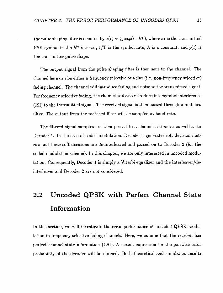
2.2.1 System Model
A general mathematical model for a frequency selective Rayfeigh fading channel is
the tapped delay fine model shown in Figure 2.2.
Figure 2.2: Tapped Delay Line Channel Model
Here, xr; represents the transmitted PSK symbol in the kih interval. For conve-
nience, we assume that the zk's take on one of the M possible values from the set
(&?zn/tZ.i. , n = 0, I,. . . , A4 - 1). According to Figure 2.2, the corresponding received
symbol yk is
where the hkjfst j = 0,. . . ,N, are correlated, zero-mean complex Gaussian random

CHAPTER 2. THE ERROR PERFORMANCE OF UNCODED QPSK 17
variables with a certain correlation matrix, and nk is a zero mean complex Gaussian
random variable with a normalized variance of unity. The hkjYs represent the effect
of frequency selective fading while the nk's represent the effect of the channel's white
Gaussian noise.
The kfh received sample in (2.1) can be written in matrix form as
where
is the k f h channel state vector and
is the kth data vector. In this study, we assume that the receiver has perfect chan-
nel state information, i.e., each Hk is known to the receiver. In practice, reasonably
accurate CSI can be obtained through channel sounding techniques such as inserted
pilot symbols f311-[32]. ?Ye will show later on in this thesis that imperfect channel
state estimation will lead to degradation in the bit error rate. With perfect CSI, the
optimal decoder is a Viterbi decoder that selects the sequence 2 = (21, iz,. . . , iN)
that minimizes the conditional probability density function (pdf) of the received se-
quence p(xly), where y = (yl, 92,. . . , yN) is the received sequence. Given the channel -cY
state estimation (H,,, Hz,. . . , nN), this is equivalent to selecting the sequence 2 that
CHAPTER 2. THE EiRROR PERFORMANCE OF UNCODED QPSK 18
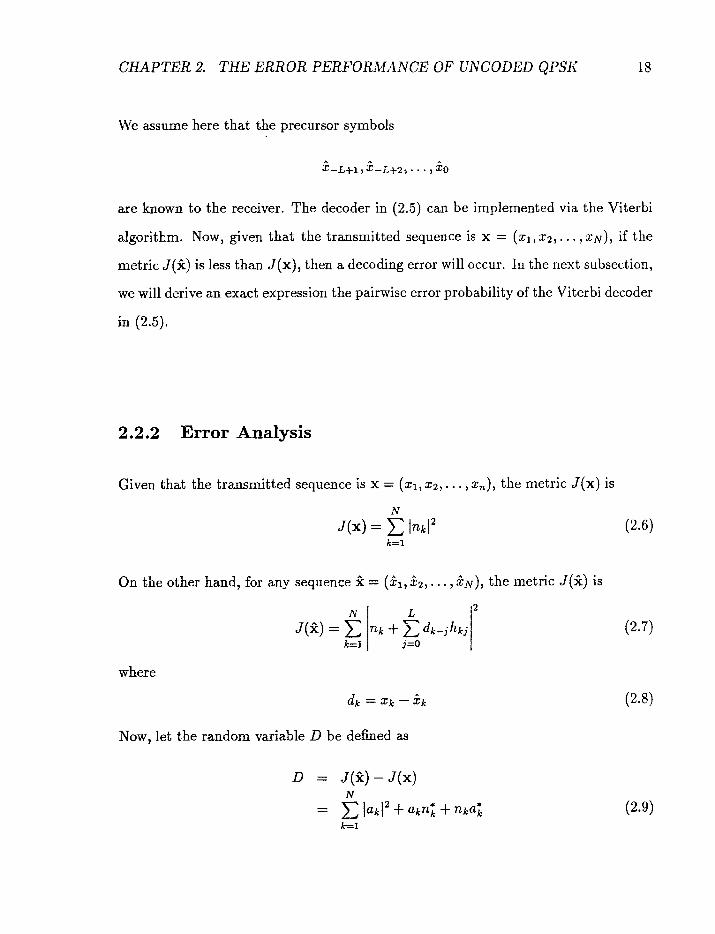
We assume here that the precursor symbols
are known to the receiver. The decoder in (2.5) can be implemented via the Viterbi
algorithm. Now, gken that the transmitted sequence is x = (xl, 52,. . . , xlV), if the
metric J (1) is less than J(x) , then a decoding error will occur. In the next subsection,
we will derive an exact expression the pairwise error probability of the Viterbi decoder
in (2.5).
2.2.2 Error Analysis
Given that the transmitted sequence is x = (xl, 2 2 , . . . , x,), the metric J ( x ) is
On the other hand, for any sequence 1 = (it1, it2, . . . , itN), the metric J(A) is
where
Now, let the random variable D be defined as

where
is a zero mean complex Gaussiar, random variable. The ak's, in general, are correlated.
Let the random vector A be defined as
where
and
This implies that the covaziitnce matrix of the ak7s is
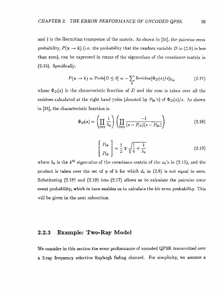
a& t is the He-mGtian traaspoose of the matrix. As shown ia [34], the pair~vise error
probabiiith P{x -+ P j Qi-e. the probability that the random variable D i ~ i (2.9) is less
than zero), c m be expressed in terms of the eigenvalues of the covariance matrix in
(2.1 5) . Speci6caBy7
where arz(s) is the ehzrzcteristic famction of D and the sum is taken over all the
in 1341, the chmaicteris'tic &'unction is
where X k is tbe kt' eigemahe of the covariance matrix of the uk's in f2.15), and the
product is taken over the set of q of k for which dk in (2.8) is not equal to zero.
Substituting (2.18) arrd (2.19) into (2.117) allows us to calculate the pairwise error
event probabilityB which in turn enables us to calculate the bit error probability. This
be given in the next subsection.
2,2.3 Example: Two-Ray Model
KTe consider in t&s sef:&~ the error performance of uncoded QPSK transmitted over
a %ray fiequency sekcti~e Rq-lei& fading channel. For shplicity, vie assume a
CHAPTER 2. THE ERROR PERFURLMANGE OF UNCODED QPSK 2 1
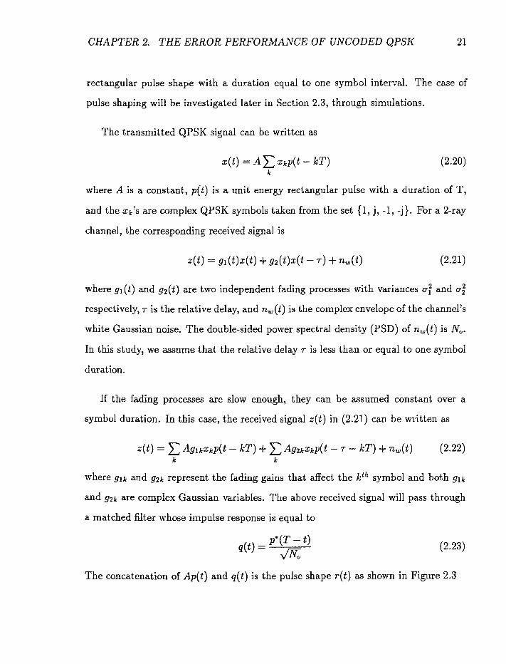
rectangular pulse shape with a duration equal to one symbol interval. The case of
pulse shaping will be investigated later in Section 2.3, through simulations.
The transmitted QPSK signal can be written as
where A is a constant, p(t) is a unit energy rectangular pulse with a duration of T,
and the xkfs are complex QPSK symbols taken from the set (I, j, -1, -j]. For a 2-ray
channel, the corresponding received signal is
where gl(t) and g2(t) are two independent fading processes with variances a: and a:
respectively, .r is the relative delay, and n,(t) is the complex envelope of the channel's
white Gaussian noise. The double-sided power spectral density (PSD) of n,(t) is No.
In this study, we assume that the relative delay T is less than or equal to one symbol
duration.
If the fading processes are slow enough, they can be assumed constant over a
symbol duration. In this case, the received signal z(t) in (2.21) can be written as
where glk and g2k represent the fading gains that affect the kfh symbol and both glk
and g2k are complex Gaussian variables. The above received signal will pass through
a matched mter &ose impulse response is equal to
The concatenation of Ap(tj and q(t) is the pulse shape r(t) as shown in Figure 2.3

Figure 2.3: The matched filter response
After matched filtering, the resultant signal can be written as
where n(t) is the filtered noise with a variance equal to
The filtered signal y(t) is sampled at instance kT, k being integers. The k th sample is
where
and Ag2'k-x
hkl = ,/'N,
P'

CHAPTER 2. THE ERROR PERFORlMAiVCE O F UhiCODED QPSK 23
Note that the variance of the random variable hko is
where
In this study, the tot& received signal energy is denoted by
Similarly, the variance of hkl is
Finally, for any pair of k and j
where Jo(*f is the Bessel function of zero order and fD is the maximum Doppler
frequency. ft should be pointed out that the autocorrelation function of the fading
processes gl ft) and g2ft) are respectively a; Jo(2afDr) and o,2 J0(2r fD7) [31], where 7
is t.he delay variable.
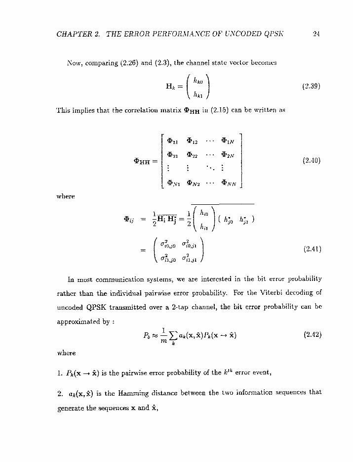
compit*iag (2.26) arid j2.3), the channel state vector becomes
This implies tkax the cmzdatioi; matrix gHH in (2.15) can be written as
where
In most commuxGcation systems, we are interested in the bit error probability
rather than the individual pairwise error probability. For the Viterbi decoding of
uncoded QPSK transmitted over a 2-tap channel, the bit error probability cart be
approximated by :
where
1. P,[x -., 1) is f he pairwise error probability of the kih error event,
2. ak[x,2) is the P_amt;ring distance between the two information sequences that
generate the sequences x and jl;

3. m = 2 is the number of infarmation bits per symbol, and
4. the sum is over the set of error events that merge in no more than 3 szeps in
the trellis diagram obtained from the intersymbol interference pattern. This trellis
diagram is show^ in Figwe '5.4.
There are 4 states in tire ~reEs; one for each of the 4 s_vrnbofs. According to the
tretlis diagram, there are 3 md 9 error events of length 2 and 3 steps respectively. As
;a result, there ate 12 exor events being used in bit error approximation in (2.12). It
should be pointed out that it-, our alcarfation: the transmitted sequence is assl~med to
be the all-zero sequence in the trellis diagram. We have incorporated error events of
merge length 4 into the bit- error probability approximation. HaxseverF they cause only
minor changes to the end results. Consequently, we believe that the approximation
reffects the actual bit error rate ~easnabfy r d l .
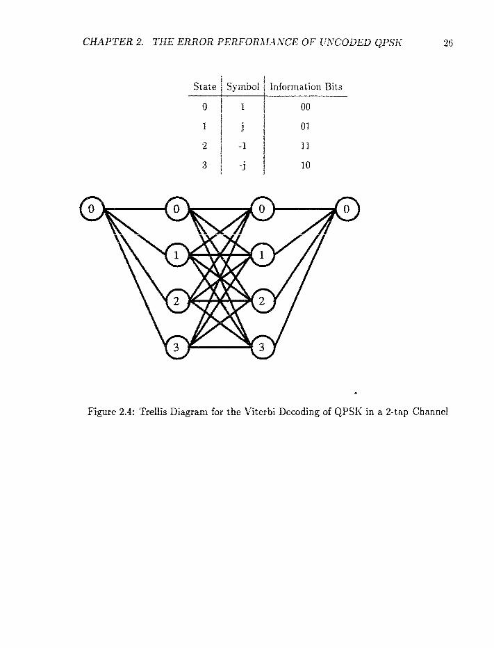
! State I Symbol 1 Information Bits
Figure 2.4: Trellis Diagpm far the ti'iterbi Decoding of QPSK in a %tap Charmel
CHAPTER 2. THE ERROR PERFORXfANCE O F UNCODED QPSK 27
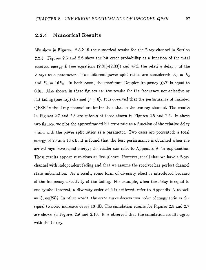
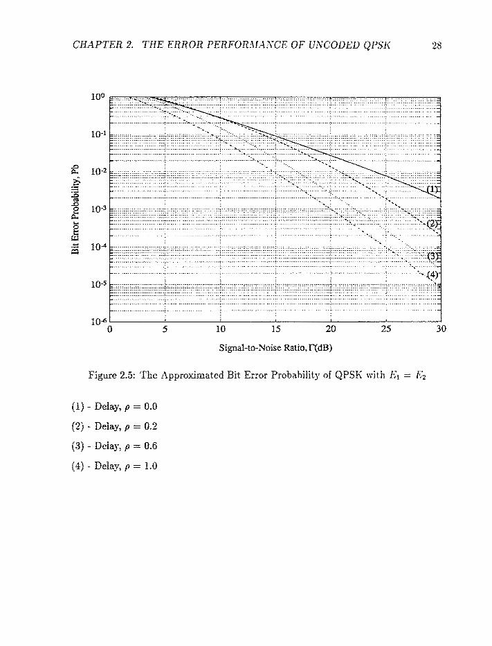
22.4 Numerical Results
We show in Figures. 2.5-2.10 the numerical results for the 2-ray channel in Section
2.2.3, Figures 2 3 and 2.6 show the bit error probability a s a function of the total
received enere- E (see equations (2.31)-(2.33)) and with the relative delay T of the -
2 rays as a parameter. l'wo different power split ratios are considered: El = Ez
and El = 16E2. In both cases, the maximum Doppler frequency fDT is equal to
0.01. Also shos-o in these figures are the results for the frequency non-selective or
flat fading (one-ray) cbannel (r = 0). f t is observed that the performance of uncoded
QPSK in the %ray chairnei are better than that in the one-ray channel. The results
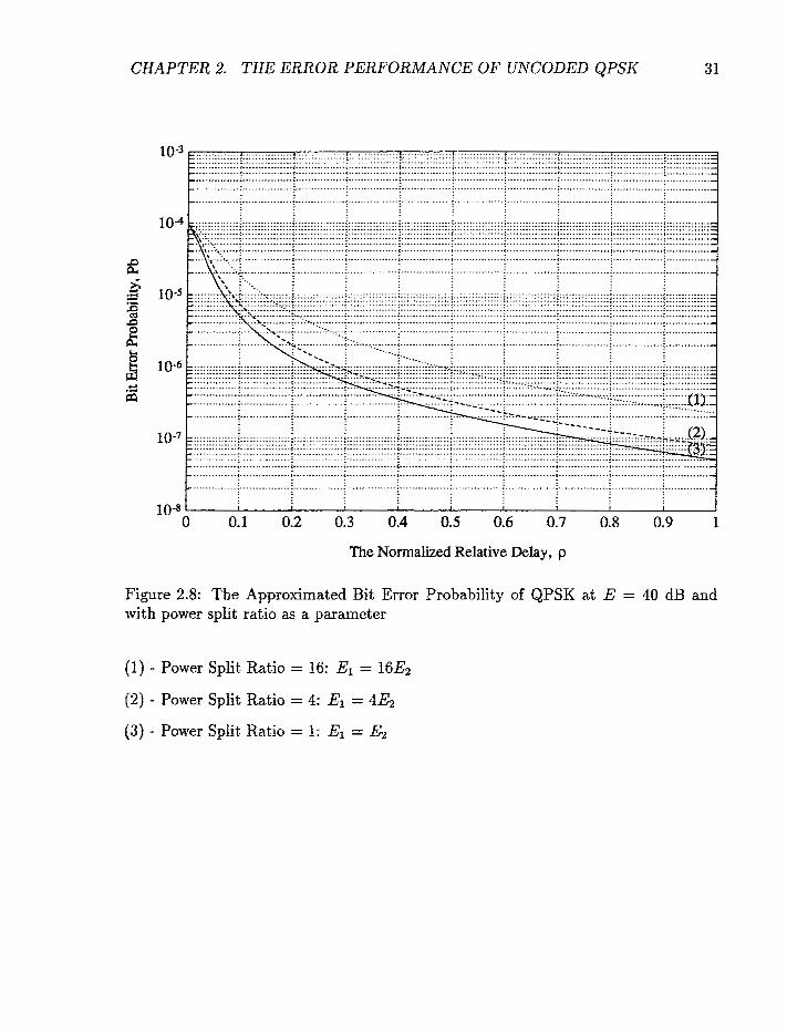
in Figures 2.7 and 2.8 are subsets of those shown in Figures 2.5 and 2.6. In these
two figures, we plot the approximated bit error rate as a function of the relative delay
T and with the power split ratios as a parameter. Two cases are presented: a total
energy of 20 and 10 dB. It is found that the best performance is obtained when the
arrival rays have equal energy; the reader can refer to Appendix A for explanation.
These results appeaf suspicious at first glance. However, recall that we have a 2-ray
channel with independent fading and that we assume the receiver has perfect channel
state information. -2s a rmult, some form of diversity effect is introduced because
of the frequency sefectivits of the fading. For example, when the delay is equal to
one-symbol intend, a &.it-ersity order of 2 is achiesed; refer to Appendix A as well
as f3, eqf23)E. In other :t.ords, the error curve decays two order of magnitude as the
signal to noise increases every fO dB. The simdation results for Figures 2.5 and 2.7
are shown in Figares 2.3 axid 2.10. It is observed that the simulation results agree
with the theory.
Signai-to-Noise Ratio, TfdE3)
Figure 2.5: The Approximated Bir Error Probability of QPSIi with Er = f;;2
(1) - Delay, p = 0-0
(2) - Delay? p = 0.2
(3) - Delay? p = 0.6
(4) - Delay7 p = 1.0

CHAPTER 2. TNE ERROR PERFORMAIVCE OF UNCODED QPSK
............. ............ ............. ................ ................................. l. , r.. : , .......... : ............................................. ................................................................................................................................ -
......... ................ ................................. ................................. ... .............. -.... .......,.. _....___..I____I__._____________I_______ _....___..I____I__._____________I_______ _....___..I____I__._____________I_______ _....___..I____I__._____________I_______ _....___..I____I__._____________I_______.._....___..I____I__._____________I_______ ,...,, .............................................................. - ................................................................. ....................
............................ . . . ................ .............................. ..,....... ... ... ......... .....
................ . . . . . . . . . . ........... : ............... ............... : i
................ ..............
............. ........... ............... ................ .............. ................ ................ ................ .............. ................ ................ - t 1 ............... ;
..... .............. ................ - : : ................ ............ .............. . . . . . . . .
....................................................................................................................................... - ................ ............. ................ . . . . . . . . ................ - .............. < ................ & < g. j ................ ; z i
............... ...................................................................... - .................................................. ................................. . ................. .............. - < i.... ................................... < 8
........ ................ ........... ................ ................................. .............. ................ - < +.. ............... 5
- ............................................................................................................................... -
lo4 0 0:1 012 0:3 014 0:s 0:6 0:7 018 d 9 1
The Normalized Relative Delay, p
Figure 2.7: The Approximated Bit Error Probability of QPSK at E = 20 dB and with power split ratio as a parameter
(1) - Power Split Ratio = 16: El = 16&
(2) - Power Split Ratio = 4: El = 4E2
(3) - Power Split Ratio = I: El = E2
CHAPTER 2. THE ERROR PERFORMANCE OF UNCODED QPSK
The Normalized Relative Delay, p
Figure 2.8: The Approximated Bit Error Probability of QPSK at E = 40 dB and with power split ratio as a parameter
(1) - Power Split Ratio = 16: El = 16Ez
(2) - Power Split Ratio = 4: El = 4Ez
(3) - Power Split Ratio = 1: El = Ez


CHAPTEB 2. THE ERROR PERFORl%fAs\TCE OF UNCOIfED QPSK
Figure 2.10: The Simulated Bit Error Probability of QPSK at E = 20 dB and with power split ratio as a parameter
Solid Line - Analytical Results
(1) - Power Split Ratio =
(2) - Power Spfit h t i o =
(3) - Power Split Ratio =
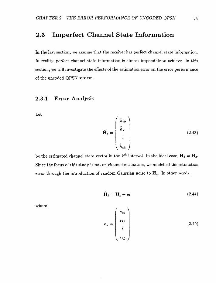
2.3 Imperfect Channel State Information
fn the last section, we =sume that the receiver has perfect channel state information.
In reality, perfect channel state information is almost impossible to achieve. 1x1 this
section, we mill investigate the effects of the estimation error on the error performance
of the uncodeci QPSK system.
2.3.1 Error Analysis
Let
be the estimated charnel state ~ e c t o r in the kth interval. In the ideal case, H~ = Hk.
Since the focus of this study is not on channel estimation, we modelled the estimation
error through the introduction of random Gaussian noise to Hk. In other words,
where

CHAPTER 2. THE ERROR PERFORMANCE OF UNCODED QPSK 35
is a random Gaussian vector with a covariance matrix of aEE = a;I, where I is a
( L + 1) x (L + 1) identity matrix and (L + l)a: is the power of the estimate noise.
tiVe assume €?k is independent of Hk.
The Viterbi decoder will select the sequence P = 2 2 , . . . , ? N ) that mini~i~izes
the metric -
Given the transmitted sequence x = ( ~ 1 ~ x 2 , . . . , x,), the metric J(x) is
For any other sequence 2, the metric J(k) is
If vie define the random variable D to be

CHAPTER 2. THE ERROR PERFORMANCE OF UNCODED QPSK 36
where
then a decoding error will occur if the random variable D is less zero. Thus? random
variable D can be written as
where
CHAPTER 2. THE ERROR PERFORMANCE OF UNCODED QPSK 37
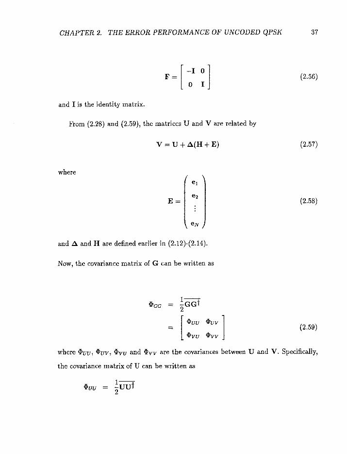
and I is the identity matrix.
From (2.28) and (2.591, the matrices U and V are related by
V = U + A ( H + E )
where
E =
and A and H are defined earlier in (2.12)-(2.14).
Now, the covariance matrix of G can be written as
where aUu, Quv, avU and Bvv are the covariances between U and V. Specifically,
the covariance matrix of U can be written as

where
and
Recall that, 5: and ( L + ljt?,2 are the variances of the noise and the estimated error
respectively.
Similarly, we can easily determine BUv, Qrvu and Qrvv. If we define the matrix W as
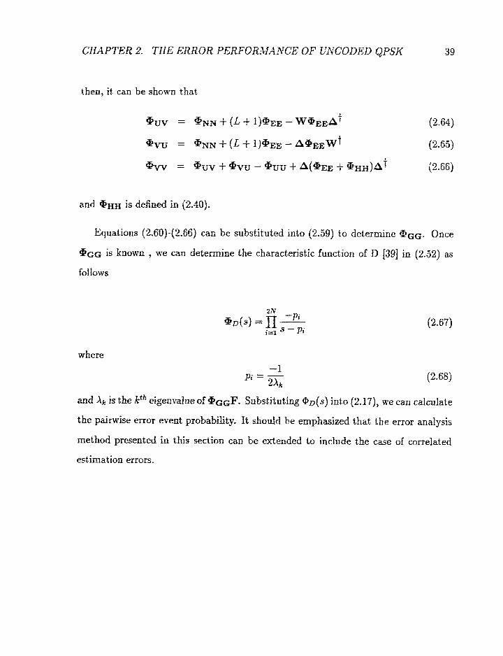
then, it. can be shown that
and @HIf is defined in (2.40).
Equations (2.60j-Q2.56] can he substituted into (2.59) to determine aGG. Once
@GG is known , 1%-e can determine the characteristic function of D [39] in (2.52) as
follows
and Xk is the iEfh eigemdue of @G@. Substituting @o(s) into /2.17), we can calcufate
the pairwise error event probability- It should be emphasized that the error analysis
method presented in this section c m be ex-tended to include the case of correlated
estimation errors.

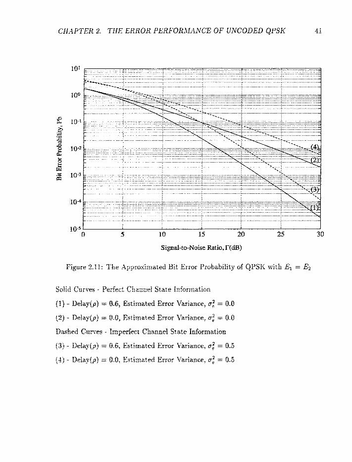
2.3.2 Numerical Results
Figares 2.11 to 2.15 show :he r,urr,erIca! results for the 2-ray channel with imperfect
chutnel state infarmation(GS1). fa each figure, solid curves represent the result for
perfect CSI whereas isthe dashed curves represent the results for imperfect CSI. The
Doppler frequency for ail the figures is 0.01 and the variance of the estimated error, a:,
is 0.5. This corresponds to an estimate noise of unity (since L = 1). The actual channel
noise power also a s s t m a tbe szrne value, In other words, we assume that the channel
noise is irreducible iio the channel estimation process. Figures 2.11 and 2.12 show the f .. tz;E-error probabiky zs a fx=tctioa of the to id received energy E and with the relative
delay 7 of the 2 rays as a parameter. It is observed that the performance of uncoded
QPSK in the %ray charinel is still better than that in the one-ray channel. However,
%he performance of pedect CSi is about 3 dB better than that of the imperfect CSI.
This is predictable since ;be estimator noise is equal to the channel noise,
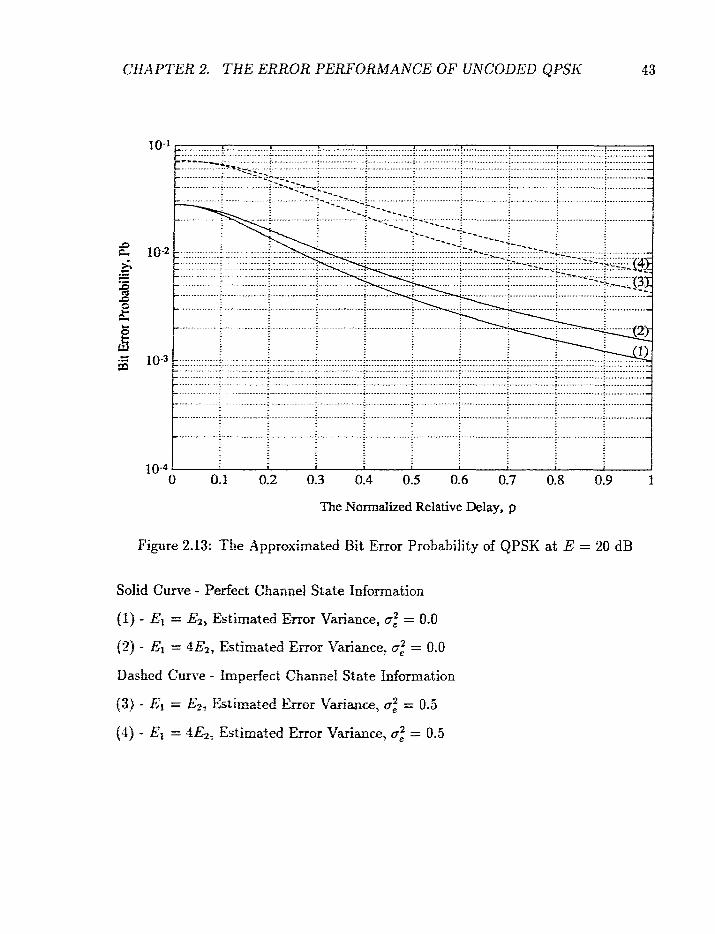
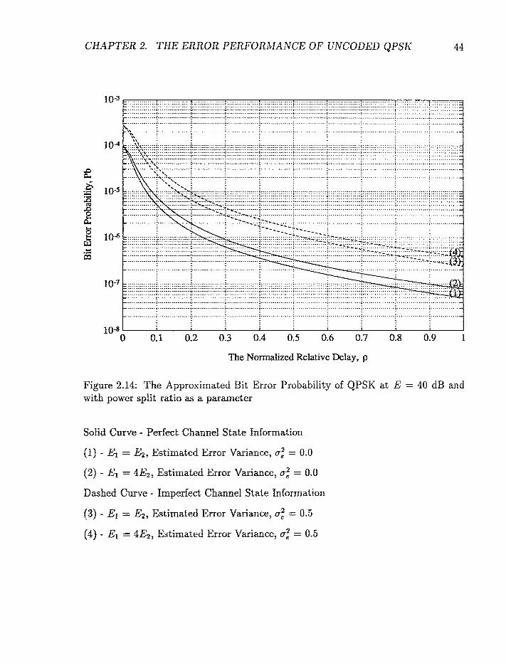
The results shown in Fi,wes 2.13 and 2.14 are the bit error rate as a function of
the delay T and with rhe power split ratia as a parameter. Two cases are presented: a
total energy of 20 dB and 40 dB. It is found that the best performance is still obtained
when the afrid rays have equd energ;. These two figures obviously show that the
system xi& perfect chzmef staie inforrssztion performs better than the one without.
All of these resufts c m be interpreted as z loss in energy. Theoretical and simulation
resrrfts of the uncoded QPSK madnlatiox system with perfect and imperfect CSI are
shown Figures 2-15 a d '2.16. From these two figures, it is found t!mt the simulation
results match it-h &e therjry ;.when the signal-to-noise is above 20 dB. However, the
sinrdation results show rEzr rHe p e r k t CSf system is oniy about 2 dB better than
the imperfect CCI system (the tbeoreticd results show a 3 dB difference).
CHAPTER 2. THE ERROR PERFORMAXCE OF GNCODED QPSK
Signal-to-Noise Ratio, T(dB)
Figure 2.11: The -4pproGmifted Bit Error Probability of QPSK with El = Ez
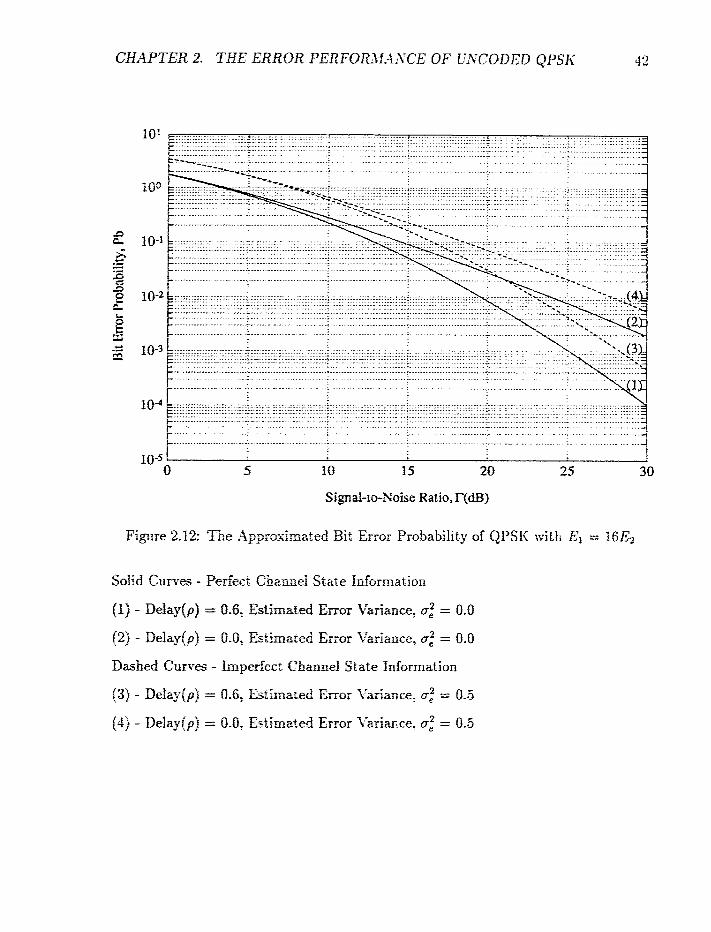
Figure 2.12: TEe AppraxErnrtt,ed Bit Error Probability of QPSK with El = 16E2
The Nom&ed Relative Delay, p
Figure 2.13: The Approximated Bit Error Probability of QPSK at E = 20 dB
CHAPTER 2. THE ERROR PERFORA.fA?JCE OF UNCODED QPSII'
The Normalized Relative Delay, p
Fiewe 2.14: The Approximated Bit Error Probability of QPSK at E = 40 dB and with power split ratio as a parameter
SoEd Curse - Perfect Chamel State Information
(1) - El = E2: Estimated Error Variance, (T: = 0.0
(2) - El = 4E2, Estimated Error Variance, a: = 0.0
Dashed Curve - Imperfect Channel State Information
f 3) - El = E2? Estimated Error Variance, a: = 0.5
(4) - El = 4E2, Estimated Error Variance, a: = 0.5

CHAPTER 2. THE EBROR PERFORMANCE OF UNCODED &PSI<
..........
.....................................................................................................................................................................
10-5 f I I
0 5 10 15 20 25
Signal-to-Noise Ratio, E(dB)
Figure 2.15: The Simulated Bit Error Probability of QPSK with El = Ez
Solid Curves - Perfect Chvlnel State Idormation
flf - Delayfp) = 0.6, Estimated Error Variance, a: = 0.0
(2) - Delay(p) = 0.0, Estimated Error Variance, a: = 0.0
Dashed Curves - Imperfect Channel State Information
(3) - Delay(p) = 0.6, Estimated Error Variance, a: = 0.5
(4) - Delay(p) = 0.0, Estimated Error fiariance, a: = 0.5
CHAPTER 2. THE ERROR PERFORiK4NCE OF UNCODED QPSK
The Normalized Relative Delay
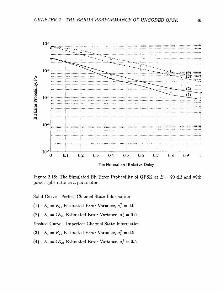
Figure 2.16: The Simulated Bit Error Probability of QPSK at E = 20 dB and with power split ratio a s a parameter
Solid Curve - Perfect Channel State Information
(I) - El = E2, Estimated Error Variance, a: = 0.0
(2) - El = 4E2, Estimated Error Variance, a: = 0.0
Dashed C w e - Imperfect Chamel State Information
(3) - El = E2, Estimated Error tTariance, 0; = 0.5
(4) - El = 4Ez, Estimated Ermr Variance, a," = 0.5
CHAPTER 2. THE ERROR PERFORA4.4il;rCE OF UNCODED QPSK 47
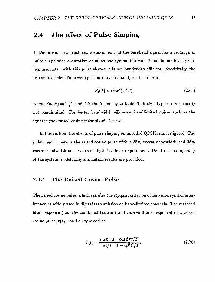
2.4 The effect of Pulse Shaping
In the previous two sections, we assumed that the baseband sign& has a rectangular
pulse shape with a duration equd to one symbol interval. There is one basic prob-
lem associated with this pulse shape: it is not bandwidth eificient. Specifically, the
transmitted signal's power spectrum (at baseband) is of the form
&fz) where sinc(2) = : and f is the frequency variable. This signal spectrum is clearly
not bandlimited. For better bandwidth efiiciency, bandlimited pulses such as the
squared root raised cosine pdse should be used.
In this section: the effects of pulse shaping on uncoded QPSK is invest-igated. The
pulse used in here is the r&ed cosine pulse with a 35% excess bandwidth and 35%
excess bandwidth is the cment digital cellular requirement. Due to the complexity
of the system model, only simulation results are provided.
2.4.1 The Raised Cosine Puke
The raised cosine pulsez \r%ch satisfies the Xyquist criterion of zero intersymbol inter-
ference, is widely used in digital trztnsmission on band-limited channels. The matched
filter response (i-e. the combined transait and receive fi!ters response) of a raised
cosine pulse, rft), can Ire expressed as
sin af jT cos p ~ t / T r(i) =
at/T f - 4B2t2/T2
CHAPTER 2, TBE ERROR PERFORJIANCE OF UNCODED QPSK 48
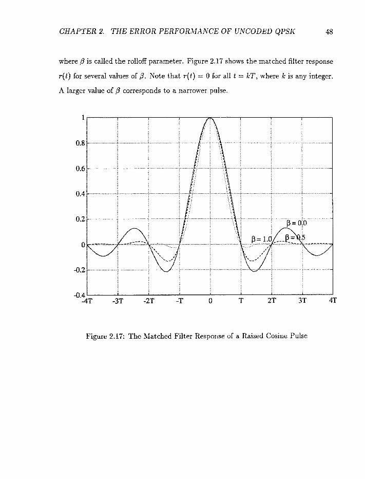
where p is called the rolloff parameter. Figure 2.17 shows the matched filter response
r ( t ) for several -v;ilues of 3. Kote that r ( t ) = 0 for all t = kT, where k is any integer,
A larger value of ,& corresponds to a narrower pulse.
4.4 '- -42' -3•‹F -2T -T 0 T 2T 3T 4T
Figure 2.11: The Matched Filter Response of a Raised Cosine Pulse

CHAPTER 2. THE ERROR PERFORMANCE OF UNCODED QPSK 49
2.4.2 Simulation Model
Fiom Figure 2.17, it can be deduced that the presence of a delay arrival ray will
introduce intersymbol interference which in turn causes degradation in the bit error
rate. In this case, the corresponding received sample, yk, can be written in the form
The infinite sum in the above expression causes two problems in our study. First, an
infinite number of terms is not realizable and cannot be generated by a computer.
Consequently, a finite number of interference terms must be determined and we trun-
cate the channel impulse response to 16 symbols. A detail explanation of this choice
of truncation length will be given later in this section. The second problem is the
decoding complexity of the Viterbi decoder. The decoding complexity of the Viterbi
decoder is proportional to 4L, where L is the length of the channel impulse response
and 4 is the size of the QPSK constellation. As we can see from (2.71), if the length of
the channel sequence is infinite, the decoding complexity of the Viterbi decoder will
be infinite as well. If the length of the impulse response is 16, the decoding complexity
will be equal to 4'". Clearly, such a Viterbi equalizer is still not realizable. Thus, the
receiver has no choice but to assume that the channel memory is short. The Viterbi
equalizer used in this study assumes a memory of 2, or 16 states in the decoding trellis.
ff we choose a memory of 3, then there are 64 states io the decoding trellis and the
decoding complexity is increased by a factor 4. Such a large number of states is not
practical in simulation. On t.he other hand, a reduced complexity decoder will yield
gmd performance at moderate to fnw channel SNR but will generate an irreducible

CHAPTER 2. THE ERROR PERFORAMNCE OF UNCODED QPSK 50
error floor due to the truncation of the channel response. This is because the residual
energy in the truncation signal acts as irreducible noise and therefore, an irreducible
error floor will occur. In summary, we use in our signal generation the mudel
and use for the Viterbi decoder the metric
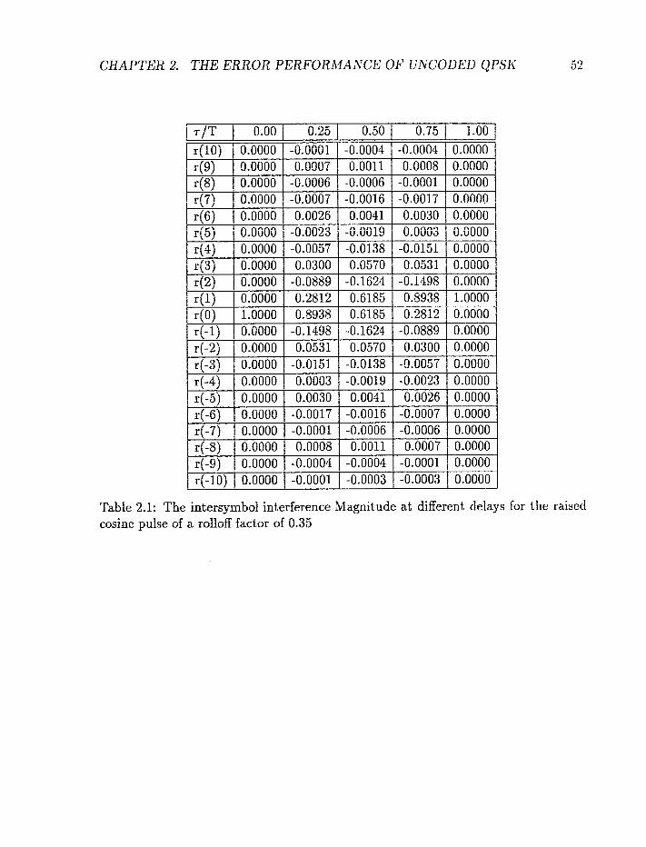
Table 2.1 lists the intersymbol interference magnitude at different delay T for a
raised cosine pulse with a rolloff factor of 0.35. The first column in Table 2.1 is the
time interval of the transmitted symbol and the second to the fifth columns are the
matched filter response at diRerent delays of the second arrival ray. In other words,
where r(t) is the raised cosine pulse in (2.70). From Table 2.1, the reader will observe
that the magnitude of the intersymbol interference diminishes as the time difference
between the signal and the interference term increases. After 8 time intervals, the
magnitude is almost zero. Therefore, we truncate the pulse to 16 symbols (8 on
each side) in the simulation. Note that the residual energy at the truncation point
is 0.0037%, 0.0097% and 0.0089% for relative delays equal to 0.25, 0.5 and 0.75,
respectively.
i n the simulationT we assume that the fading processes are slow enough that they
can be assumed constant over 16 symbol duration. In this case, the received signal yk

CHAPTER 2. THE ERROR PERFORMANCE OF UNCODED QPSK
can be written as
where glk and gzk represent the fading gains that affect the bth symbol , T is the
relative delay and r(k) was defined in (2.74). In addition, glk and g2k are independent
of each other.
Now comparing (2.72) and (2.75), it is observed that
It should be pointed that hko and hkj are correlated.
The Viterbi decoder will perform detection based on the trellis diagram shown
in Figure 2.18. There are 16 states, one for each combination of the 2 previous
transmitted symbols. In other words, each state represents (xk-Z, x ~ - ~ ) . There are 16
states because the Viterbi equalizer assumes the length of the channel memory to be
2. If the Viterbi equalizer assumes the length of the memory to be 3, then the trellis
diagram will have 64 states.
CHAPTER 2. THE ERROR PERFORAIANCE OF UArCODED QPSK
Table 2.1: The intersymbol interference Magnitude at different delays for the raised cosine pulse of a rdlofF factar of 0.35
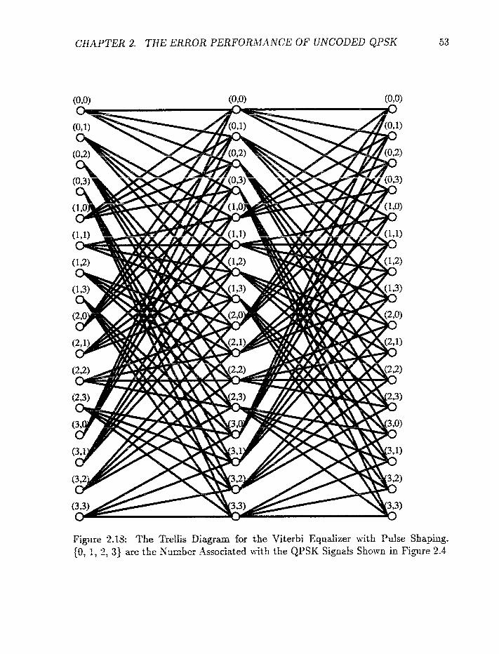
CHAPTER 2. THE ERROR PERFOR-tIi\A7CE OF UNCODED QPSK 53
0 . - Figure 2-18: The Trellis Uiagmm for the Viterbi Equdizer with Pulse Shaping. (0. I , 2: 3) are the Sunher Assaciated with the QPSK Signals f hown in Fi,gure 2.4
2.4.3 Numerical Results
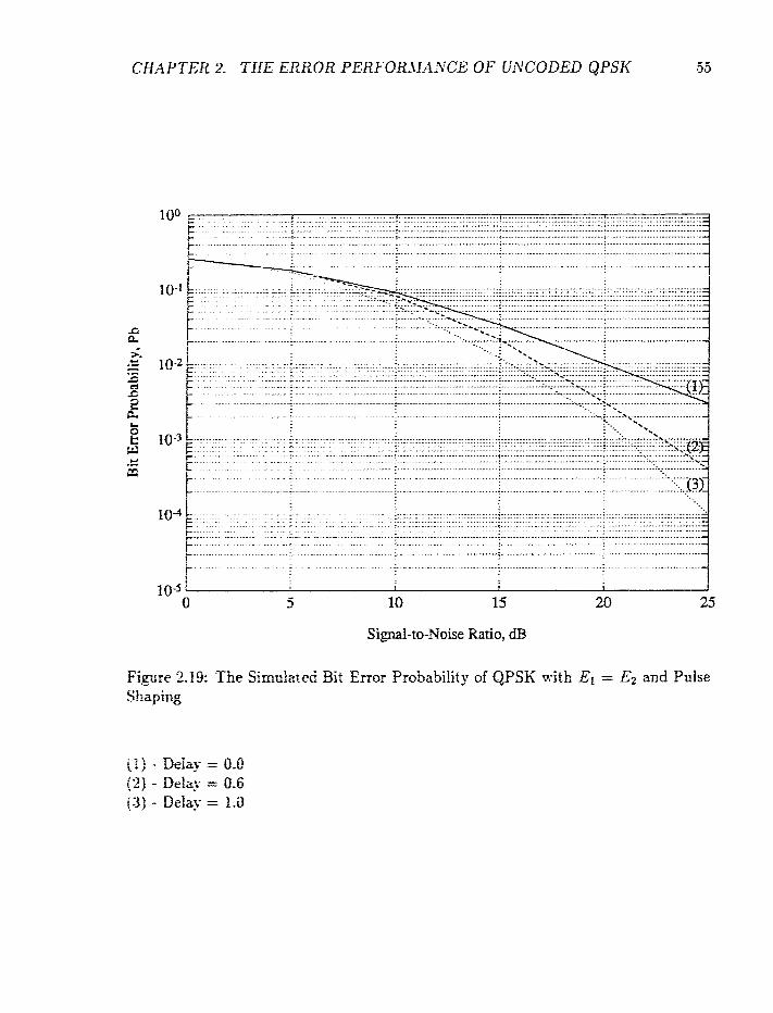
Figures 2.19-2.21 &O~S the simulation results for the 2-ray chamel 1%-ith pulse shaping.
The pulse used is the raised cosine pulse with the rolloff factor, .3, equal to 0.35 and the
fade rate of t h e e simulation resrtlts is 0.01. Figure 2.19 shows the bit error probability
as a function of the xotd received energy E and with tile relative delay uf the 2 rays
as a parameter. The simulation result is obtained under the condition that the 2 rays
have equal p o w (power split ratio = I). It is found that the performance of the 2
ray channel is stif1 better than that of the flat fading channel (one ray channel). For
delays fess &zm m e s y ~ b i j : duratim, we found that the larger the relative delay, tile
better the periormace.
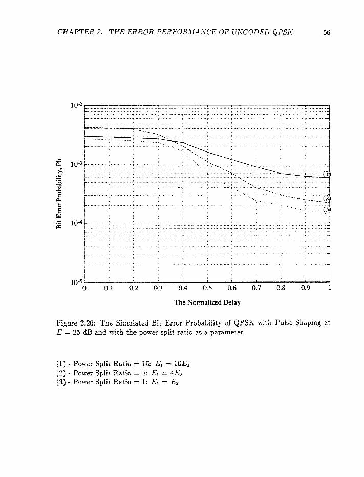
Figure 2.20 illwrrates the effect of the relative delay as iri-ell as the power split ratio.
The simulation red-rf-ts are o5tained whe;i the total energy of the 2 ray is ey ual to 25
dB. From this figare: it is observed that 'the best performance is obtained when tltc
arrival rays haye e q d eeIierrgy= Io addition, Figure 2.20 also supports the cor~ciusiori
of Figure 2.19: the higber the relatk-e delay. the better the performa~ce.
fin all^., Figure 2.21 demctnstrates the effect of the ro fM factor, 3, on the bit error
rate. The simakiricro was ca-xied atit at a total received energy equal to 25 dB and
with equal power split. F m Figwe 2.31, we can see that tile higher rdfoff factor,
he better the error pedo-mmce. The aos t significant improvement is seen when the
roifaff factor increases &om Q to 0.4.
Signal-to-Noise Ratio, dB
Figwe 2.19: The Simulated Bit Error P~rabability of QPSK with El = E;, and Pulse Shaping
The ?;ormalized Delay
Figwe 2.20: Tae Simulated Bir Error Pmbability af QPSK with Pulse Shapirrg at - * E = 25 dB and xiah the pofrer spirt rzrk as a parameter
(1) - Posver S p k Ratio = 86: E3 = I&& (2) - Puwer Split Ratio = 4: El = 4E2 (3'1 - Power Split Ratio = f : Ei = Ez
CHAPTER 2. THE ERROR PERFORMANCE OF UNCODED QPSK
?lie Rolloff Factor
Figure 2.21: The Simutated Bit Error Probability of QPSK with Pdse Shaping at E = 25 dB and with Equd Pm-er Split

CHAPTER 2. THE ERROR PERFORMANCE O F UArCODED QPSK ti8
2.5 Summary
We studied in this chapter the error performance of a Viterbi receiver used for decoding
PSK signals transmitted over a frequency selective Rayleigh fading channel. We found
that in the case where the frequency selective fading is introduced by the presence
of 2 propagation paths, the channel provides an implicit diversity effect that helps
t.o improve the error performance over that of a flat fading channel. 1% studied
the uncoded system with both perfect and imperfect channel state information. In
the imperfect CSi case: we assume an independent estimated error with the sarne
magnitude (varia~cej i ~ f the channel xoise. The analytical and simulation results
show that the channel still provides an implicit diversity effect. However, the error
performance with imperfect CSI is about 3 dB worse than the perfect one, as expected.
Furthermore, the eEects of pulse shaping are also investigated. The pulse used is a
raised cosine puke with a rolloff factor of 0.35. It is found that the raised cosine pulse
pelforms better than the rectangular pulse. In addition, with pulse shaping, the Zray
channel stiff performs better than the one-ray (flat fading) channel.
APTER 3
Trellis- Coded Modulation
The conventional way to improve the error performance of a communication system
is to apply forward enor correction codes (FEC). However FEC Ieads to bandwidth
expansion which is not desiraMe in bandlimited applications. Alte-mativel51, we can use
TCM which can provide coding gain without bandwidth expansion. This is achieved
through consteflation expansion, rather than signal dimensionality expansion found
iri conventional FEC systems. TCM Eras gained popularity since its introduction in
f 982 by Ungerbmk [I 2;.
The perfomaoce of any coded system mainly depends on its free Euclidean dis-
tance, which is the minimum Edidean distance between paths that diverge from any
state and remerge at the sane state after some delay. As mentioned earlier, TCM ac-
complishes the coding gain without Sandedth expansion by coding onto an expanded
G g z d co~~teEatioii sa that the fie E.sc2bea &stance is m a e e d . For an additive
white Gaussriu noise cHasoelF the cuatrudion of close to optimal trellis codes can

CHAPTER 3. TRELLIS-CODED MODULATION
be performed on the basis of the following heuristic rules:
(1) Parallel transitions (when they occur) in the encoder trellis are assigned to
signal points separated by the maximum Euclidean distance.
(2) The transitian originating from and merging into any state is assigned the
same set of signals.
(3) The signal points from each subset should occur an equal number of times in
each state.
Rules (1) w d (2) guarantee that the Euclidean distance associated with sing!e
and multiple paths that diverge from any state and remerge at the same state has a
maximum free EucEdean distance. Rule (3) guarantees that the trellis code will have
a regular structure. X ~ r e w e r , rules (1) and (2) will involve the concept of "mapping
OF set partitioning, which d l be discussed later in this chapter.
Since the introduction of the 2-Dimensional TCM by Ungerboeck[l2], extensions
were made to obtain multidimensional TCM [35]-[38]. Trellis codes based on 4, 8, and
16-dimension& s i s a l consreffations have been constructed and some of these codes
ha= been implemented in commercid_v available modems 1353. One of the advan-
tages of multidimensionaf TCM is that 1r.e can use smaller constituent 2-dimensional
signal consteBations that d o w a tradeoff between coding gain and irnplement,ation
complexity Recently? a sew design technique for TGM based r,q lattice and co-sets
of a sublattice has been de-t-eloped
The m&hin parposes of this chapter are to design new TCM schemes fox digital
ceEdar corrrmmicatlms, to coffipare the new trellis codes with conventionaI coding
CHAPTER 3. TRELLIS-CODED MOD ULATI0.N 6 1
systems that use convoiutionaf code in conjunction with :-QPSK modulation and,
specifically, to investigate the feasibility of using TCM to replace convolutional codes
in digital cellular applications.
The chapter is orgmized as follows: Section 3.1 presents the general trellis coded
5-QPSK T system. Section 3.2discusses the design procedure of our new trellis coded
modulation schemes. Three new treflis codes are designed: the 8 state, rate 312 code;
the 8 state, rate 31.3 code; and the 16 state, rate 212 code. Tbe code rate in this thesis
is defined as the rsumber of input bits per channel symbol. The simulation results for
these three trellis codes are given in Section 3.3. Their comparisons with convolutional
codes are given in Section 3.4. In addition, we present in Section 3.5 two 64 state
codes designed with the same approach as those in Section 3.3, and compare their
performance wifb the 32 state corn-olutional code proposed for the digital celluIar
application. Finally2 a summary of tbis chzpter is given in Section 3.6. It should
be pointed out that xhe resuits presented in this chapter apply only to flat fading
channels. The e m r perfamance of the %ray frequency selective fading channel will
be given in the next chapter.
3.1 Trellis-Coded %-QPSK
:i fdormat5ioil Bits i Phase Change ir
00 I X - i 4
i ; 3" 4
18 l i
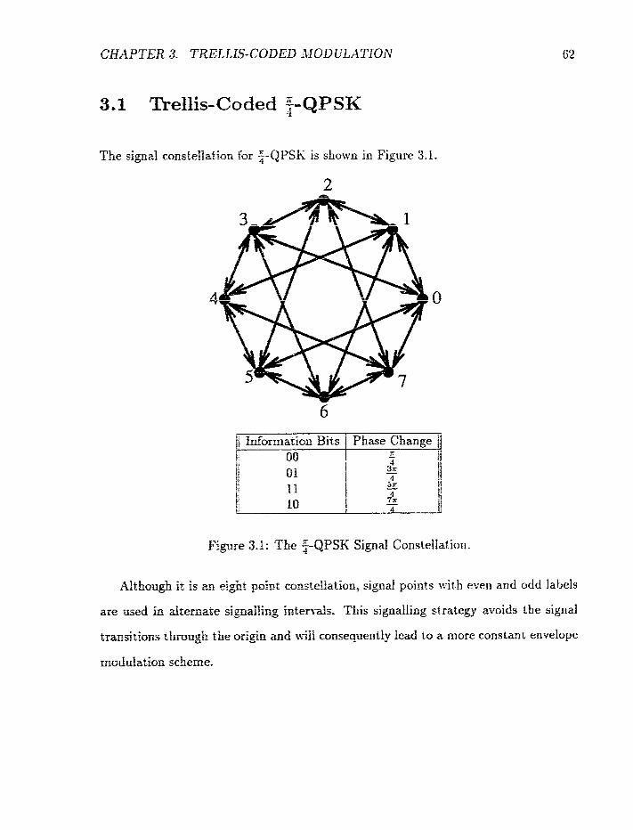
F@e 3.1: The $-QPSK Signal Consteilation.
Althou& it is u eight p i n t ccr.zstftllation, signal points i ~ i i h even and odd Iabels
are wed in dtemizte sigaaBiing Ineerrds. This signalling strategy avoids the signal
transitions thmrrgb the m-igin and id cfinsequently I d to a more coristant enretope
msduhticr~l scheme,
CHAPTER 3. TRELLIS- CODED MOD LTLATION
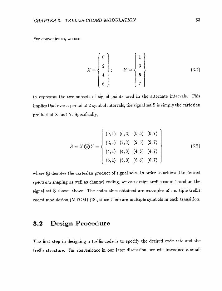
For convenience, we use
to represent the two subsets of signal points used in the alternate intervals. This
implies that over a period of 2 symbol intervals, the signal set S is simply the cartesian
product of X and 3'. Specificall_v,
where @ denotes the cartesian product of signal sets. In order to achieve the desired
spectrum shaping as -rd as channel coding, we can design trellis codes based on the
sign& set S shown above. The codes thus obtained are examples of multiple trellis
coded modulation fMTC31) !18], since there are multiple symbols in each transition.
3.2 Design Procedure
The first; step in desIgC-g a ~ r & k code is to specify the desired code rate and the
r,reliis structure. For eonsecience in o w later discussion, lye will introduce a s m d

CHAPTER 3. TRELLIS-CODED i2IODEILATION 64
distinction between the code rate and the throughput. The code rate will always be
given as a rational number. 4 rate k/n code is one that encodes E bits of information
into n modulation symbols in each encoding interva:. The throughput, on the other
hand, is the code rate expressed as a real number. By adopting this convention,
we can conveniently distinguish the structures of codes with the same throughput.
With ;-QPSK being the modulation format, the throughput must be lower than 2
bits/symbol in order to achieve a significant coding gain. The code rates considered
in this chapter are 3/2? 3/3, and 2/2, which translate into throughputs of 1.5 and 1
bits/symbol.
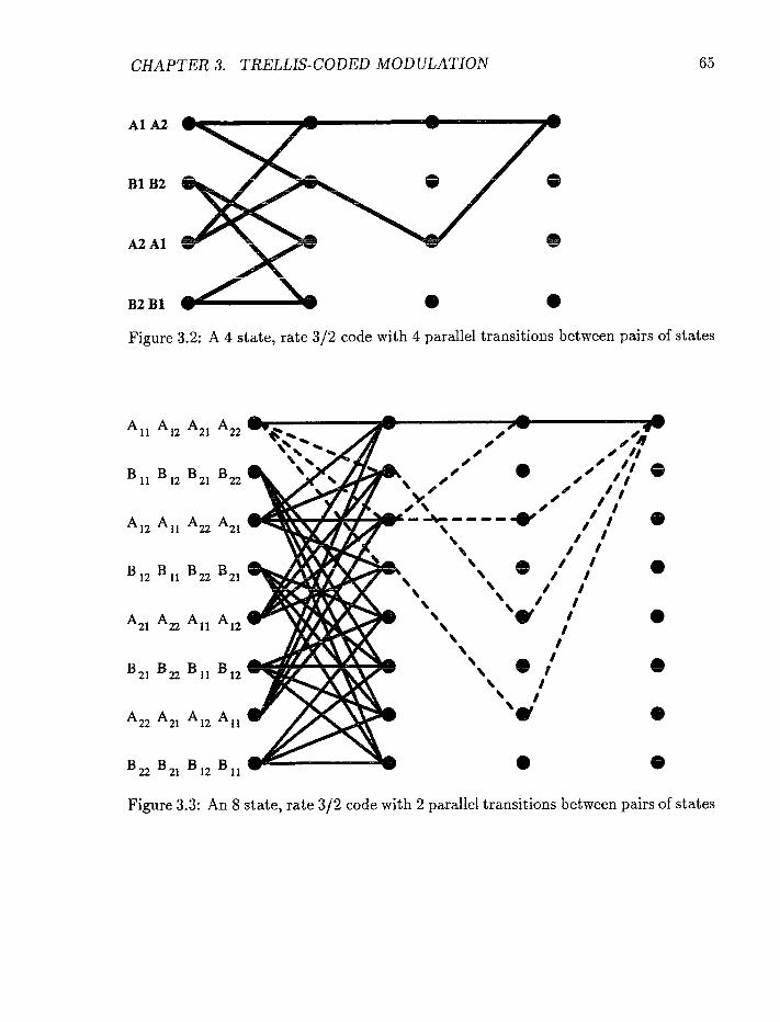
3.2.1 Rate 3 / 2 Codes
The two trellis structrrres shown in Figures 3.2 and 3.3 can be used to encode 3 bits
of information into 2 modulation symbols using 2-QPSK. The detail explanation of
the 8 state, rate 3/2 code will be given in Appendix B. The encoder in Figure 3.2
has four states with 4 parallel transitions between pairs of states. On the other hand;
the encoder in Fieme 3.3 has 8 states but only 2 parallel transitions between pairs of
.-a ~bates. + Both encoders exhibit regularity and symmetry I121 and all the transitions in
the two encoders receive symbol-pairs from the set S in (3.2).
CHAPTER 3. TRELLIS-CODED MODULATION
Figure 3.2: A 4 state, rate 3 f 2 code with 4 parallel transitions between pairs of states
Al l A12 A21
B1, 12 B21 B22
A12 All A22 A~~
B12 BIl B22 B21
A21 A, A l l A12
3 2 , B, E l , 312
A22 A,,
Figure 3.3: An 8 state, rate 312 code with 2 parallel transitions between pairs of states
CHAPTER 3. TRELLIS-CODED MODULATION 66
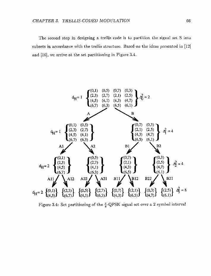
The second step in designing a trellis code is to partition the signal set S into
subsets in accordance with the trellis structure. Based on the ideas presented in 1121
and [16], we arrive at the set partitioning in Figure 3.4.
Figure 3.4: Set partitioning of the 2-QPSK signal set over a 2 symtol interval

As shown in Figure 3.4, the original signal set has an intra-set squared Euclidean
distance of A; = 2: while subsets in the next three layers have iatraset distances of
A: = 4, 0; = 4, axid 4,; = 8. Atthough there is no gain in distance from the first
level to the second, this is of no concern in this study because of the trellis structures
used; see Figures 3.2 and 3.3. We also note that the symbds assigned to the same
subsets in the second and third Seveis of the partitioning tree are all different. This
guarantees that trellis structures with 2 or 4 parallel transitions between any pair of
states will have a free Hamming distance (at the symbol level) of 2. As pointed out
in [I '71, the order of diversity provided by a trellis code is aspptoticafly equd to its
free Hamming disia~ce. Thk is the performance criterion emphasized in this study.
Finally, to complete the design of a trellis code, we h a ~ e to appropriately assign
the subsets in Figure 3.4 to the transitions of the encoder. Once again, we adopt
Ungerboeck's heuristic code design rdes 1121: transitions originating and terminating
at the same state must receive signals from the same subset, and pardel transitions
should receive signals from subsets in the lowest level of the set partitioning tree.
The signal mapping for the 4 and 8 state codes are shoxt-n in Figures 3.2 and 3.3
respectively. We can deilrrce em$!)- from these figures that the minimnm squared
Euclidean bistacce, 6: is 4E or 6E6 for the 4 state code2 itad 822 or 12Eb for the 8
state code, where E is the symbol energy and Eb is the bit energy When compared
to nncoded QPSK whose mioimum squared distance is SEj, the 4 state rode provides
a coding gain of 1.2 dB in the AIYGS chamel while the 8 state code pro\~ides a 4.8
dB gain. 111 addition, these rwo codes provide a second order diversity effect in a
fuify interleaved fading c'nmnef, since both have a free Hamming distznce, d ~ , of 2.
Finatiy, it should be pinred out that the 8 state code compared favorabfy against a
sirnifar code in the hzerath~e for the XWGX channel application. The 8 state, rate
312, SPSIC code ia [16j has a squared Euclidean distance of 5.17E, which is 2 dB
less energy eEcIenr &an our code in the * W G N charme!. Ifowever, tile codc i l l j iG]
can provide a third order dii-ersity effect for fading applicatiorns. o m more tliari that
provided by otlr 8 srare code. This loss in diversity is the price we have to pay in
order to achieve spectrum shaping via :-QFSK.
It is clear &om the set partitioning tree in Figure 3.4 that in order to have a
rate 3/2 code with 2 squared distance greater than 8E , there must not exist any
parallel transitions in the trellis bizgram. This together with the requirerntrit that
transitions originating zad terminzting at the same state must receive sigtiafs from
the same subset implies that at !east 64 states are required :o improve the squared
distance to beyond 8E. The encoder of a 64 state, rate 3 f2 code with no paraltc!
transitions will consist of 3 inpnr branches tvith two 1-bit delay eIcntcnts in each
branch. Conseqi;entl> there exists error events of length equal to 3 steps i11 thcb
trellis. The sqaared Euciidean distances of these error events h a ~ c a loiwr i~ourtd
equal to 4E + 2E -+ 3-23 = 10E. \shere 4E is the intraset distance for sigrial subsets
A and B, and 2E is the Zntesset & s t a c e between A and B- This a 6-I stale code
can provide a coding gain of 5.7 dl3 over QPSK in the AJVG?; channei. It is possible
to increase the s i p r e d Eilstmce further to 12E. To achieve this, a 51 2 state code is
required. This grecttly iinc~ezses the decoding complexity.
3.2.2 Rate 3 f 3 and 212 Codes
To encode i1iifim2tion 2: a throughput ui I bitfs_vmbol, 5:-e can use codr~~ with rates
q3zl 3/3 md 29, 3 Faie 3/3 c d e car, he &tzincd fWm a rate 3 / 2 by
repeatjizg one symbol in each tramition of the rate 312 code. Specificajly, if we &ride
the ',rcffis of a r&Ee 3/? code into periods of 2 intervals and labelled the 4 symbols
sent in each period by
[ ~ I ~ C ~ ~ C ; , C ; ) (3 .3 )
then the 6 symbols smt- by the corresponding rate 313 code in the same period is
A rate 3 / 3 code obtrldmed &is way clearly has a periodic sipal mapping (the period is
equai to 2 encoding interds) . This is unavoidable if we are to conform to the 2-QPSIC
modulation format i.;itfi an odd number of symbols in each encoder transition.
1% have applied the technique mentioned above to obtain a rate 3 f 3 code from
tbe 8 state, rate 3p2 cade in Figwe 3.3. The tatter will be referred to as the mother
code. The squared Eucfidezn distance oi the rate 3 / 3 code is 10E, with E = Eb.
Consequentllv, a 4 dB co&g gain is achieved by the mother code. Moreover, this
cock can provide a bird arder time dirersity in fading applications: one more than
that provided by rkie morhez code.
Zr is also possible t-o achiei-e a throtrghput of 1 bit/syrnholb:; using rate 212 cotics.
Tlfe rate 212 code shoiw in Figure 3.5 has 16 states with no parailct traasitio~ls
between pairs of states. irs bas the same decoding complesir_r 3s the rate 333 code
rneationed in tk last paragraph. It should be pointeJ out that, for a rate k/ t l trellis
code with i't: m n b e s of states: the decoding complexity is proportio~lai to the total
mimber of channel symbols in all the encoder transitions [lSj. i.e.
n C = - operations/information bit.
A-
where n is the n - ~ ~ ~ b e r of infomatimi bits, k is the number of transmitted symbols
and XS is the numSer of states.
A s for the enor perfomJmce; the 16 state? rate 212 code has a Eucfideart distance
equal to 10E [witis E = E+j and a free Hamming distance of 5. Based on these
fipres and those sEsv,-o in the last paragraph: we can predict that the rate 21% code
aad the rate 3/3 code will haw ro11gh4~- the same error performace in the AMGGN
cbzmneL Hm-ever, the r ~ t e 2,62 code is preferred in fading applications due to its
higher diversity order. Xthoagb the rate 2,d2 code outperforms the rate 3/3 code i ~ i
fading applications, the fatter has rhe &&antage that it can be used in corijunctio~i
mi& its mother code (the 8 state? rste 3f2 code in Figure 3.3) to provide unequal
enar protection [liif. Ibis is of pa&xfr?s importance for applications such as digital
speech &ere &&rent speech elements E a ~ e different sensitivities to trai~smission
errors. Since the Fate 3/3 code is d e d d horn the rate 3 / 2 code {or vice vcrsaj, it
ge~era l sllgoritkm cslni be used far decoding in both cases.

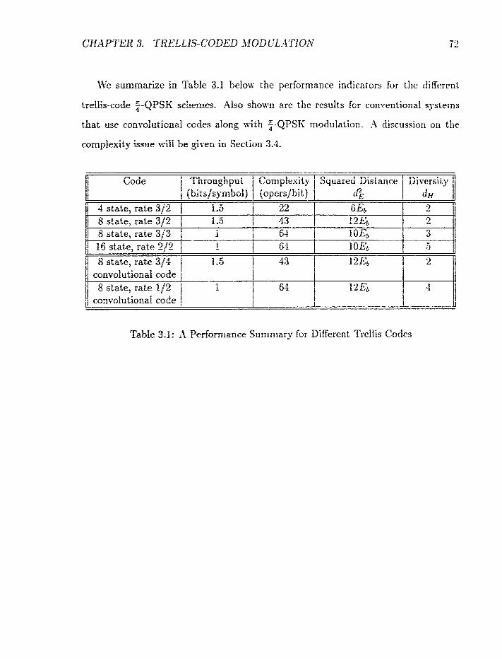
CHAPTER 3. TRELLIS-CODED MOD tZdTIO.8 72
We summarize in Table 3.1 b e h - the performance indicators for the different
trelEs-code 2-QPSK schemes. Also shrtwr.n are the results fm rm~entional systems
that use con~oiutitlrnai codes along with 2-QPSK modulation. A discussion oia the
cora~plexity issue i:-iB be g k n in Section 3.1.
k Code Il
4 state, rate 3f2
11 8 state, rate 3/3 1 16 state, rare 2/2
/j 8 state, rate q 4 convolu tional code
convolutiond code
-.I I nrougbpui j Complexity Squared Distance 1 Diversity 1
TabIe 3.1: X Performance Summary for Different Treilis Codes

3.3 Simulation Results
?Ye have determined by sirndation the bit error performance of the 8 state, rate 3 f 2
code, the 8 state, rate 3/3 code and the 16 state, rate 212 code. Both the AWGN and
the Rayleigh fiat Ehciing citannels have been considered, and in both cases, perfect
coherent detection as6 soft decision maximum likelihood decoding were assumed.
Furthermore, far the Rqleigh fading channel, we assumed that ideal interleaving and
perfect information about the fading gains are available. It shoidd be pointed out
that in general, a mobile comr~iunica~ion channel will introdzce frequency selective
fading and it is our I~tention to ei-entuzilg test our codes in such an environment; see
Chapter 4.
The simulation res-&s oi our TCM schemes are shown in Figures 3.6 and 3.7,
along with uncmded QPSK and Ungerboeck% 8 state PSK code 1121 as om reference
systems. The Unge~boeck's 8 state PSK code has an asymptotic coding gain of 3.6
dB compared to mcoded QPSE in the AWGS channel, and it provides a second
order diversity efiecr in the fading envi:iroment. It is observed from Figure 3.6 that
for the AWGN chamel and m error rate of lo-', the 8 state: rate 312 code is about
1.5 dB mare energy efficienr thm Ungerboeck's code and 4.2 dB mofe efftcient than
unccrded QPSK. This figwe a g e s quite well with the asymptotic mlrres predicted
in Section 32.1. Howe~er~ both the 8 state, 3/3 code and the 16 state, rate 212
code are s14gbtlj= worse thar: the 8 statet rate 312 code in the -4TVGT channel. As
mentioned earlier, the rate 3/3 code and the rate 312 code can be used in conjunction
to p x i d e u ~ : e ~ ' ~ : d error pzarec&m For ti& appflcation, the bit SXR is no longer the
meanindul mesrrre af eaergy eSccienc3- because the rate 3/3 code is nohoptima1 in
the sense of bit SSR. Rather, the symbd SSR should be used instead. Ln this case,
the rate 313 code is a b m t 1 dB more efficient than the rate 312 code in the A!i!GN
chamel.
Figare 3.7 illustrates the performance of our codes in the flat fading channef. In
the fading chamel, the 8 state, rate 3J2 code is consistentl_v about 2 dB better than
Ungerboeck's code. ft should be pointed out t h a t the throughput of this codc is
only 75% that 0.f Cagerboeck's. As mentioned earlier, the rate 313 and the rate 2/2
codes perform worse than the 8 stare, rate 3 / 2 code in the AKGX channel. Hotvevcr,
they perform sigdicantiy better than the rate 3 / 2 code in the fading channe l due to
their higher diversity orders. This is especially true in the case of the rate 2f2 code
where a bit-error probabiiity of lo-' can be achieved in the fading charrncl wit11 a
signal-to-noise ratio (SKI%) as small as If dB.
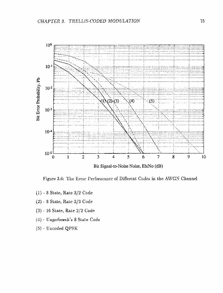
CHAPTER 3. TRELLIS- CODED MUD LEATIOX
Bi; Signaf- noise Noise, Ebmo (d3)
Figure 3.6: Tire Enor Pedormasce of Different Codes io the Ati5GS Cfiannel
j l ) - 8 State, R a e 3/2 Coiie
(2) - 8 Stale, Rate 3/3 Code
(3) - I6 State, Rate "22 Code
(4) - t;ngerbwck's- 8 State Cade
(3) - Encoded QPSK
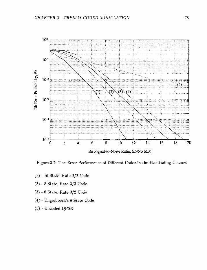
2 4 6 12 14 16 18 20
Bit Sipat-10-Noise Ratio, EbfNo (dB)
Figare 3.1: The Error Per"cif51iance of Different Codes in the Flat Fading Ciiannel
ft) - I6 State, Rate 2/2 Code
(2 ) - 8 State, Rate 3/3 CoGe
(3) - 8 State, Rate 312 Code
(4) - Vngerbaeck's 8 State Code
( 5 ) - Uncoded QPSK
3.4 Comparisons with Convolutional Codes
We want to address in rhis section the question of how well the trellis codes com-
pare with conventional systems that use convo1utionaI code in concatenation with
z-QPSK 4 rnodulatioa. frr order to obtain a fair comparison, only codes with the same
throughput and with the same decoding complexity will be considered.
Let N: be the number of states in the convolutional code, k' be the number of input
bits per encoding intervaf, and nf(assume an even number) be the number of output
bits per interval, Then the decoding complexity for the conventional system, which
is proportional to the number of symLols contained in all the encoder transitions, is:
Sotice that there I s a constant of 4 appearing in the above equation. This is due
to the fact that optimal fiecoding for a con~entional system ~ u s t incorporate into
the decoder trellis not s d y $fie states 0: the convolutionai code, but also the phase
states of the differenrial enc~der. There are altogether eight phase states, but only 4
states are reachable at. an? ioten-;ti. Consequently, the decoding complexity of
a coos-eentiond s~s tem is -2 rimes that of the underlying consdutional code,
To predict the error pedommce of a con-~dutional coded QPSK sfstern with
perfect CSI, we czm make use of the foBowing approximations. Let the underlying
c~tnvolutionai code hzs a free Hamming distance (at the bit level) of df7 then the
sqrrzed Euctidearr distance of the combined spstem is
6; z 2djE
CHAPTER 3. TRELLIS-CODED MODULATION 78
The free Hamming distance (at the symbol level), or equivalently the diversity order,
d j even d, x { 2 d j odd
These approximations can be explained as follows. If a convolution code with
a free Hamming distance of d j is used in conjunction with conventional QPSK, the
squared Euclidean distance of the combined system is simply 4 = 2PEdj. However,
if 2-QPSK is used insteadi due to the differential encoding process, the squared Eu-
clidean distance may no longer be equal to 2 E d j . Actually, our previous experience
in similar systems {for example, a partial response signalling system) leads us to be-
lieve that differential eucoding will lor. ,r the squared distance of a combined system.
For the purpose of estimating the error performance of a conventional system in the
AWGN channel, we m&e the (optimistic) assumption that the differential encoding
p r o m s in z-QPSK does not change the squared Euclidean distance. Consequently,
me have the approximation in (3.7). As for the approximation in (3.81, we made use
of the fact that in any coodutlonaffy encoded QPSK system, two encoded digits
are =rapped into a channel symbol. Consequently, the free Hamming distance (at
the syz~bol lewd) of the combined system is, in the worst case, simply half the free
distance of the convoTutiona! code. However, sometimes the diversity order of a con-
ventictnaf system is better &= fiie appmximation gix-en in (3.8). A good example is
the 8 state, rate 1/2 code in Table 3.1.
The 8 state, rate 3/% code in Figure 3.3 has a throughput of 1.3 bitsfsyrnbol
and a co;rrpTexity of 43; = Tahk 3.1. This thro*l=hwt -0-r a d comp!e:ii?y car.: &r3
be acbiesed by wing rn 8 state, rate 314 convolutional code in conjitnctiorr with
=-QPSK 4 noddifatioxz. The ~~ptimat raw 3/4 convolutional code with 8 states has a
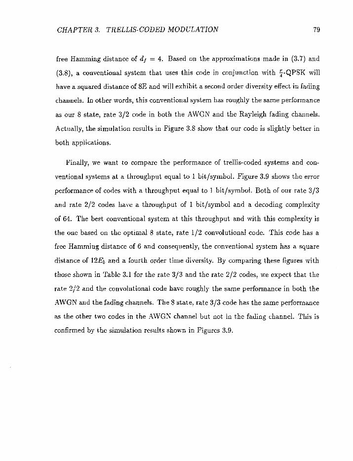
CHAPTER 3. TRELLIS-CODED MODULATION 79
free Hamming distance of df = 4. Based on the approximations made in (3.7) and
(3.81, a conventional system that uses this code in conjunction with 2-QPSK will
have a squared distance of 8E and will exhibit a second order diversity effect in fading
channels. In other words, this conventional system has roughly the same performance
as our 8 state, rate 3/2 code in both the AWGN and the Rayleigh fading channels.
Actually, the simulation results in Figure 3.8 show that our code is slightly better in
both applications.
Finally, we want to compare the performance of trellis-coded systems and con-
ventional systems at a throughput equal to 1 bit/symbol. Fi,we 3.9 shows the error
performance of codes with a throughpnt equal to 1 bit/symbol. Both of our rate 3/3
and rate 2/2 codes have a throughput of 1 bitlsymbol and a decoding complexity
of 64. The best c ~ n ~ e n t i o n d system at this throughput and \pith this complexity is
the one based on the optimal 8 state? rate I f 2 convolutionaf code. This code has a
free Hamming distance of 6 and consequently, the conventiorial system has a square
distance of 12E6 a d a fourth order time tiiversity. By comparing these figures with
those shown in Table 3.1 for khe rate 313 and the rate 2/2 codes, we e x ~ e c t that the
rate 212 and the conwlutiu~al code have roughly the same performance in both the
AWGN and the fading cfimne'is. The 8 staxe, rate 3 f 3 code has the same performance
as the other two codes in the AWGS channef but not in the fading channel. This is
corffirmed by the sirnufation resdts shorn in Figures 3.9.
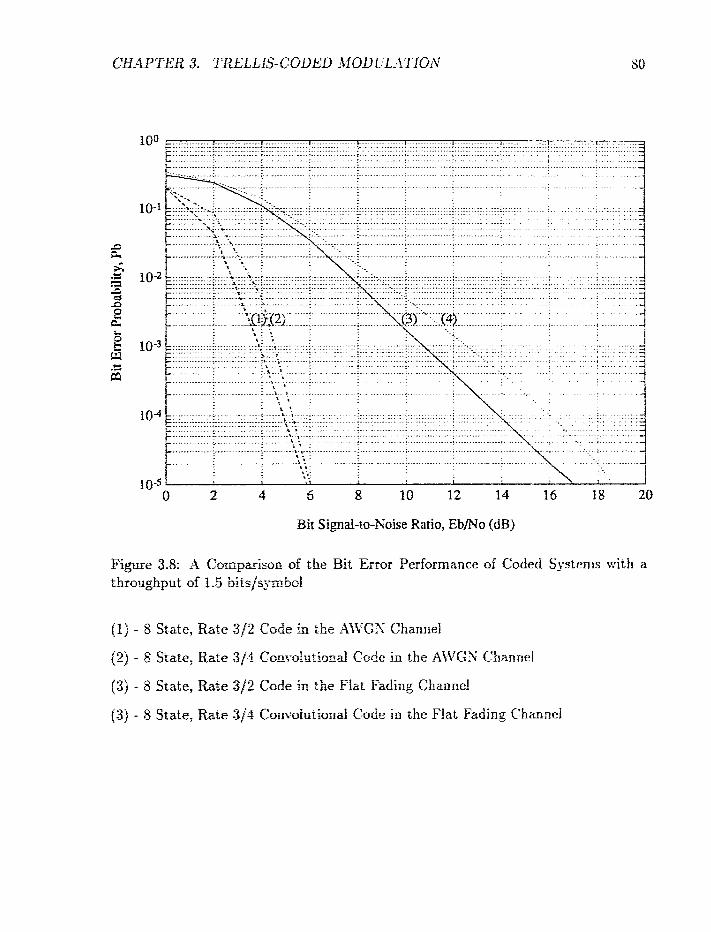
2 4 6 10 12 16 118 20
Bit Simal-to-Noise Ratio, EbfNo (dB)
Figure 3.8: X Cornpaisan d the Bit Error Performance of Cotfed S:SE~RB with a throughput of 1.5 bits/symbal
(1) - 8 State: Rate 3/2 Code in the Xfi'C-t; Channel
(2) - 8 Statet Rare 3j4 Cam-olnriond Code in the A\'tPGS f hanricl
(3) - 8 State, Rate SJZ G d e in the Fiat Fading Channel
(3) - 8 State: R a ~ e 3/4 Corn-olmtionid Code in the Flat Fading t'hirnnd
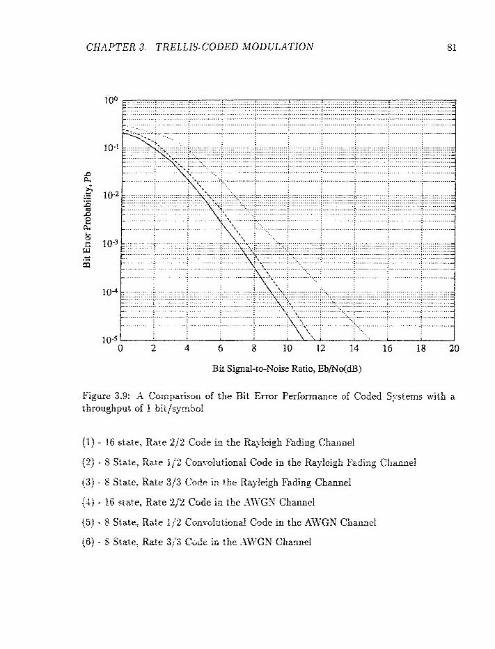
Bit f ignal-to-Xoise Ratio, EbP=rP(dB)
Figwe 3.9: -4 Comparison of the Bit Error Performance of Coded Systems with a throughput of f bii/symbol
f I) - I6 stale. Rate 212 Code in the Rayleigh Fading Chamel
(2) - 3 State, Itate :p'2 C~m-~h: iona Cede in the Rqleigh Fadi~g, Charnel
(3) - 8 State. Rare 3i3 Code in the Rqleigh Fading Channel
f 4 ) - 16 state, Rate 2 / 2 Code in the A\\-GS Channel
( 5 ) - 8 State, Raie i f 2 Convohiiond Code in the AWGS Channel
(6) - 5 State, Raw 3/3 Ca@e in :he -4ii'GS Channel
3.5 64 State, Trellis Codes and Comparison with
the IS44 Csnvolutional Code
Current digital celular communications employ the (65 , 57) 32 stale, rate 1/2 convo-
lutional code (hereafter referred to as the IS-54 code). In this section. iw compare the
peffclrmance or' tire IS-54 code with TCM schemes designed 1:-ith our approach that
have similar througbp~t and complexity. Two new TChl schemes are considered: 64
state, rate 2 / 2 64 state. rate 8 j2 codes. Both codes have single transition between
pairs of states. The 6-1 state. rate 212 code basically is an extension of the 16 state,
rate 212 code, and the 61 state: rate 3 j 2 code is an extension of the 8 state, rate 3 / 2
code. The trellis stmctrrres of these two codes are given in Appendix C.
Figure 3.10 shoxs rhe e m s ,rperfo~mance of the 64 state, rate 3/2 and the rate
2/2 trellis codes and the 32 srztte, rate 212 convolutional code. From this figure, it
is found that at an error rare of 10-% the rate 2/2 code is about 1 dB more energy
eificient than. the rate LP2cmvoiutionzi code, which is in turn about 3 dB rnore
energy efficient than the rzte 312 code. The decoding conlpiesity of the rate 3 j 2 aid
the m e 2/2 trellis codes and the rate 1/2 convoiutional code are 341.33, 512 arrtl
-712 respectively. Thus It c a be corrrludrd that the 61 stare, rate 212 treifis code is
preferred over the 32 state, raw fi-2 convc-lurionaf code. Although the rate 3/2 code
is less eoergy e%cient thzn the rate 1 f 2 convolutional code. it increases the cfmrnel
capzcity by a factor of 1.5. ia other words. the coding gain Is traded for tire chanriel . .
capac:t~ In the case of t2 sstrire, rate 3j2 trellis code.

3;: &is chapter. se pre3erzed a ~~erh.ctdcrlogy for designing xreilis-coded mod-dation
schemes that conf~mi to the ;-QPSK modulation format. The basic idea is to use
. > multiple trellis ccoies ;.;l:n z signal set which is the artesian product of the even and
odd subsets in the :-f,lPSI; signal cmste!faiion. Several good codes xith multiplicity
of 2 are designed. Airmowg them are the 8 state, rate 312 code 5%-ith a throughput
0: 1.5 bits/symbd a i d a IG state. ra te 2f2 code with a throughput of unity. The
* s
former can prwzcs z second order tiiwrsity effect in fading applications while the
!alter can provide i~ sit3 order diversity. In the AjirG;\; chamel, the rate 312 code
is about 0.8 dB more eraerg- escieat than the rate 2/2 code. Both codes perform at
!east as r~elf as jaboue "dB better! the conventional system that uses $-QPSK in
% . * - coi;jur?ction vSrh ~ o ~ ~ ~ i ~ i i o i s d codrnc, - The 8 state, rate 3/2 code is about 2 dB more
eztergj- effcienr iis.2e.1 cornpeed 3,i;iti-r the rani-olutional code ii;ith the same thoughput -
and cornpiexity. Two f2 sxate i C>i schemes are also designed: the 64 state, rate 3/52
a d the 61 state, rate 21;2 codes. These codes have throughputs of 1.5 bits/symbol
and 1 bit f s y ~ b o l respectlrek;. $%%en r he 64 state, rate 2 / 2 code is compared with
the 3.3 &te. rzte 162 ct3~a-oit~tiona: mde used in digitaf ce!iufar: it is f o n d that the
:~-e!Eis code is z b o ~ I dB nmre e n e r g e%cient than the condutional code. Rcwever,
i l. , G-! sfitfiji rate :3/2 i d k C O ~ E perfomis ii-orse than the coxoiut io~al code. This
Isss in energv can be explained 'a>- :he i~crease in channel capacity. The rate 3/2 code
ran a h b - f ..7 tirncs more users than the rate 212 TCM and the rate 112 convolutional
code.

Performance of Coded Systems in
Selective Fading Channels
-4s we rneniio~ed easfier. the motile radio commu~iication rilanttt~i is, i i ~ grneritl, it
frequency seleci-i~e fading channel. in the last two chapters, we studird the wror
performance of XQ irncoded sh-stem operating in the frequenc.i- se l tdve fatling rilarlnc~l
arrd the performance of coded systems operating in the flat fadirig chait~lcl. 'I his
chapter will combine the resuits frorn the tT.i.o previous chaprers and wiii t:vaiuate ilic
error performance of coded systems in the frequency selective fading envirunrnent.
The block diagram of such a sFstem was shown earlier in Figure 2.1. it requires a
soft decisioc generz'tor before Z'iterbi decoding of the coded modulation sc1ir:rnc. 'I'hc
structure of :his soft decision device ~ i l ! be presented in Section 4 . 1 : arid the bit error
rate ctf tbe corresponding coded s_vstems are studied in Section 4.2. X stlrri~riary of
this chapter is given in Section 4.3.
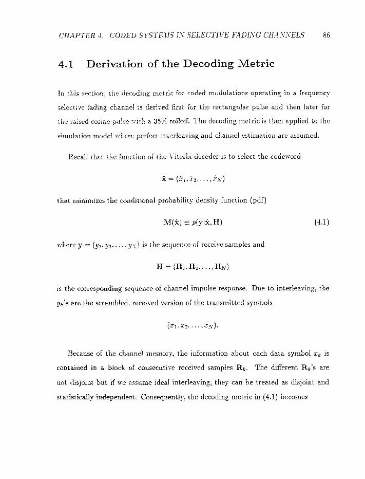
4.1 Derivation of the Decoding Metric
in this section, tbe decoding metric far coded modulations operating in a frcquencj.
selectiw fading chalrrrrel is der izd first for the rectangular pulse and then later for
t h e raised cosine p:!e 1.-i:b 2 35% rolbff, The decoding metric 13 then applied to the
i.irnt&tion model =,r;here perfec~ inrerleas-ing and channel estimation are assumed.
Recall that the func~ion oi the i-iierbi decoder is to select the codex-ord
that minimizes the coodirional pru5ability density function (pdi)
here y = (yl. y2-. - - : p:cj is the sequence of receive samples and
is t he correspondins sequence of channel impulse response. Due to interleaving, the
zjk's are the scrambled. recei~ed version of the transmitted s_r.mbols
Because of the chaonei memory, the information about each data symbol x:, is
contained in a block of comxurive receixred samples Rk. The different RkYs are
nut disjoint but i i \ye assume ideal interleaving, they can be treated as disjoint and
srafistiraliy i.sdepenbezt. Clcnsequent'r~, rhe decoding metric in (4.1) becomes
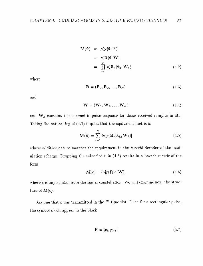
where
and Wr; contains the chaznet impulse response for those received sa~r~ples in Rk.
Taking the natural log of (4.2) implies that the equivalent metric is
1%-hose additive mt-stre matches the requirement in the Viterbi decode: of the mod-
ulation scheme. Dropping the subscript k in (4.5) results in a branch metric of the
form
where c is any symbol fro= ;fie signal constellation. We will esarrii~ie 11t:xt the strrtc-
ture of M(c).
Assume that c \.;as fransmitred in the i 'q ime slot. Then for a rectartgular pulse,
the syrfibol c sr-ill appew in the block
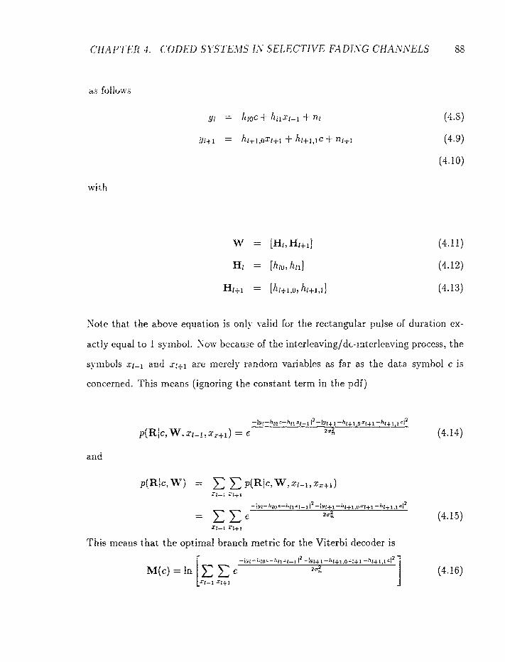
Sote that the above equation is on!y id id for the rectangular pulse of duration ex-
actly equal to 1 symbol. Sow because of the interleavingldc-interleaving process, the
symbols xl-l and s~+l are merely random variables as far as the data symbol c is
concerned. This means (ignoring the constant term in the pdij
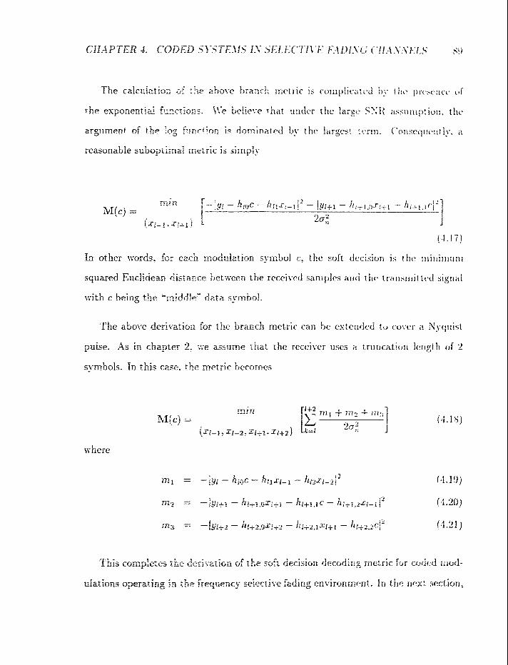
I , r ,.r- a study the errcx gerhrmance of the coded systems in the frequency selective fading
environment.
4 2 Simulation Resuits
\Z present in this sectiorn the numerical results for different codes in Chapter 3 in the
2-ra:~ heyuenc~. selective fading chancel. Figures 4.1-4.6 show the simulation results of
the 16 state, rare 2 / 2 TCIi and the 8 slate: rate 1/2 convolutional code in frequency
dect ive fading charnels. Figure 4.1 reports the bit error performance of the rate 212
code as a functiose of the tctal received energy and with the relative delay of the 2
paths as a parameter. I: is found that the best resuit is obiained whm the delay
is equal to O (fizt fadin% channel) aod the worst result is obtaitlned when the delay
is equal to 0.6. Figare 4.2 shows the egects of the normalized delay and with the
paver split ratio as a parameter. It is observed that the best performace is obtained
&er; the power split ratio Is equal to 20. IR general, the larger the power split ratio,
the better the error perftmance of a coded system. It is a!so observed that when
the power split ratio is eqcd to unit:;. the bit error probability of the trellis code
has a peak d u e zr d e h ~ = 0.5. Ho~:e~-er: when the power split ratio is larger, the
peak value is no ionget- existed. It c a be concluded that wheo the power split ratio
approaches infioits tho norn;,ef;zed &fa;- of the second arrli-a1 path does not aEect
* - the error perbmanre 0: rhe code. This is due to the nature of the decoding metric.
Far esarnpk. if the poiwr sptis ratio is l-ei5- large. the delay term (or the second fading
s --% = In ezc"iswei'r-e zzl?-ipk caa be eh ina i ed . T h s the delay of the second path
dues not a k t the ermr &mmitnce.
Figure 4.7 s h o ; ~ tiit. error performance of the 64 state, rate 212 trellis code usiilg
2 raised cosine pulse with a rolloff factor equal to 0.35. It is found that this codcs has
the same cfiararterkric its other t r e k codes. Figure 4.8 show the error perf'ori~lanc-c
comparison bet~xem the 64 sstaie: rate 2/2 code and the 32 state, rate 1/2 convolu-
tional code. Two cases ~ r j considered: delay = 0.2 and delay = 0.6. I t was f o t ~ d
that the rate 2 j2 code is better than the rare l f 2 convolutional cock by about, 1 d B a t
t i t error rate lo-". Therefore. we can conclude that TChl can repiace cor~volutiorlal
code in the celluiar appiiretion.

CEIA P TER 4. CODED SYSTEMS iAT SELECTIVE FADLYG CHAitrVEIS 92
Figure 4.1: The Error Perfcrmance of the 16 State, Rate 212 Code in a Frequency Selective Fading Channei Gsing a Rectangular Pulse and with Delay as a Parameter
(1) - Delay, p = 0.0
(2) - Delay, p = 0.3
(3) - Deiay, p = 0.5
(4 f - Delay, p = f .O
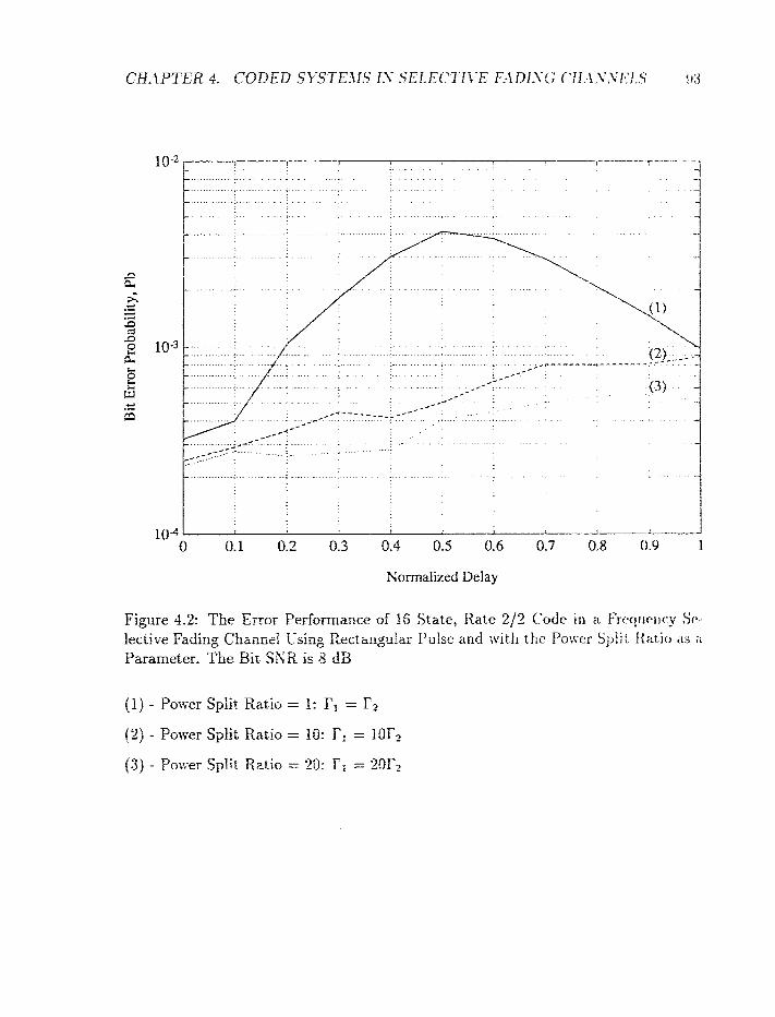
Kormdized Delay
Figure 4.2: The Error Performance of 36 State, Rate 2/2 Crsrfr: i r r a k-rrqiwrrt.y St*-
1ecti~:e Fading Channel Csing Eectmgitlar Pulse and with the Puwcr Split f i a t i c t rts zi
Parameter. The Bit SXR is 8 dB
( I ) - Poser Split Ratio = I: Fl = f2

Bi; Signal-:o-Soise Ratio, dB
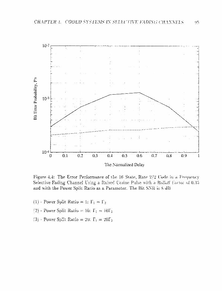
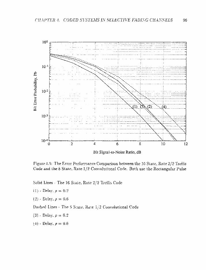
.................... ............... . . . . . . . . . . . . . . . . 10" . . . . . . . . . . . . . . . . . . ..................................... . . i ..A i..
............................................................ - . . . . ..............................
. . - .
5 - 4 8 12
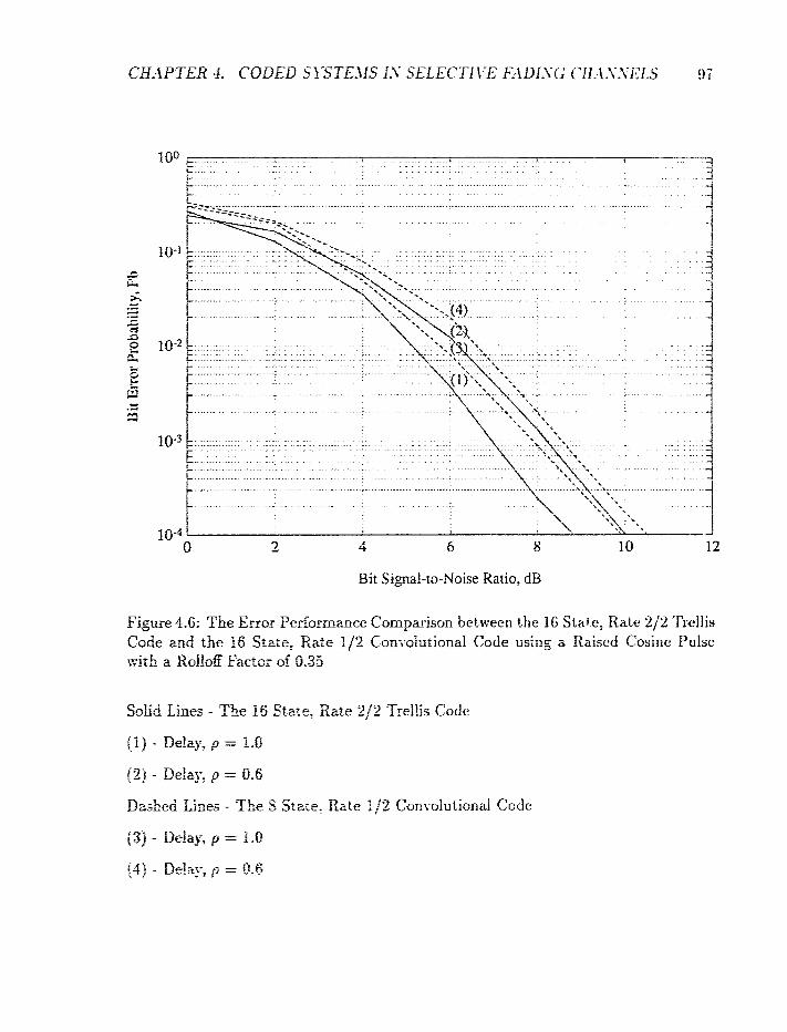
Figure 4.6: The Error Perhmanre Comparison between the 16 State; Iiate 21% 'I'rellis Code and the 16 Srate? Rate l j 2 Con;-ofutionaI Code usirtg a Raised Cosine Pulse ~ i r h 2 Rolloff Factor of 0.35
SoEd Lines - The 16 Srzre, Rzte 2J-2 Trellis Code
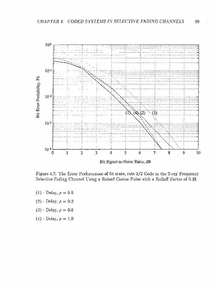
, . . . . . . ~
2 5 6 7 8 9 10
Bi: f igaaf-lo-Noise Ratio, dB
Figure 4.7: The Ermr Performance of 64 state, rate 2/2 Code in the %ray Frequency Selective Fading Chacnei Using a Raised Cosine Pulse with z Rolloff Factor of 0.35

. . . . . . . . , . . . . . .
Bit Signal-to-Noise Ratio, dB
Figure 4.8: The Error Performance Comparison between the 64 state, rate 212 Codc and the 32 state, rate 1/2 convolutional code in the 2-ray Frequency Selective Fading Channel Using a Raised Cosine Pulse with a Rolloff Factor of 0.35
Solid Line - 64 state: rate 2 /2 code
(1) - Delay, p = 0.2
(2) - Delay, p = 0.6
Dashed Line - 3-2 state: rate 112 convolutional code
(3) - Delay, p = Tr.2
(4) - Delay2 p = 0.6
4.3 Summary
In this chapter, we evaluated the error performance of coded systems operating in
the frequency selective fading channel. As opposed to what was found in an uncoded
system, it is discovered that the channel does not introduce a diversity effect in a
coded system. ft is observed that> in general, the error performance of coded systems
is the worst when the delay is equal to half a symbol and is the best when the channel
is closest to being a flat fading channel. Although coded systems perform differently
(compared to t h i s ltncoded counterpart) in the frequency selective fading channel,
TCM still performs better than convolutional codes in the frequency selective fading
channel.
Conclusions
5.1 Conclusions
In this them, we studied the performance of uncoded and coded PSK rnotlulations
operating in the frequency selective fading environment. The major objective is to
see if trellis coded rnoduiation (TCM) can be used to replace convolutional code in
the digital cellular application. The thesis consists of three major parts
(1) A performance evaluation of uncoded rxodulation: with pulse shaping, in tile 2-ray
frequency selective fading chamel.
(2) The design and performance evaluation of TCM schemes that conforrri to the - $-QPSK modulation format.
(3) A perfmmance esdilatiiiion of our TCM schemes, with puke shaping, in the 2-ray
hquency seiecth-e fading chanoei.

Details of the findings are given below. We found that in the case vhere the
frequency selective fading is introduced by the presence of 2 propagation paths, the
channel provides an impiicit diversity eiiect that helps to improve the error perfor-
mance over that of a fiat fading channel. We studied the uncoded system with both
perfect and imperfect channel state information. In the imperfect CSI case, we in-
troduce an independent estimator error with equal power as the channel noise. The
results show that the channel still provides an implicit diversity effect. However, the
error performance vAth imperfect Cff is about 3 dB worse than the perfect CSI case.
Furthermore, the effect of pulse shaping is also investigated. The pulse used is a
raised cosine pulse with a rolloff factor of 0.35. It is found that the raised cosine pulse
performs better than the rectangular pulse. In addition, with pulse shaping, the 2-ray
channel still performs better than the one-ray (flat fading) channel.
In Chapter 3, we pesented a methodology for designing trellis-coded modulation
schemes that conform to the :-QPSK moduiztion format. The basic idea is to use
multiple trellis codes with a signal set which is the cartesian product of the even and
odd subsets in the :-QPSIi signal constellation. Several good codes are designed, such
as the 8 state, rate 3/2 code with a throughput of 1.5 bits/symbol and a 16 state, rate
212 code with a throughput of unity. The former can provide a second order diversity
effect in fzding applications xrhite the latter can provide a fifth order diversity. In the
AIYGX channel, the rake 312 code is about 0.8 dB more energy efficient than the rate
2 / 2 code. Both codes perform at least as good as (about 1 dB better) the ccrnventional
system that uses $-QPSK in conjunction r ~ i t h convolutional coding. The 8 state; rate
3f-2 code is about 2 dB more energy effcient when compared with the convolutional
code with the same tkcp"dghput itnd complexity. Two 64 state TCM schemes are also
designed: the 64 state: raw 3f2 and the 64 state, rate 212 codes. These codes have a
5 2 Suggest ions for Further Research

2. A decoding afgvri~hms with significant reduction in computational complexity
are required for tire coded systems operating in the frequency selective fading channel.
r- ror the decoding me~ric derived in Chapter 4, we found a suboptimal version under
ti:.- large SSZR zsszfnptioil. Huwe~er, for small SNR, the decoding metric with the
c:xpor:entiai function should be used and its decoding complexity increases with the
cfaarmei memory. An efficient decoding algorithm for small SNR should be derived.
3. In Chapter 1. &re stated that Wilson 1151 has designed a rate 5/6 trellis code
v;itlr a throughput of -2.5 bitsjsymboi and that this code can achieve a significaqt
coding g a b in an AJi7G3 channel r&ik only sacrificing only 16% in spectral efficiency.
In our study, we preseored several I C l f schemes with a maximum throughput of
1.5 bitsfsymbol. Thus. higher throughput TCM scheme should be designed while
retaining the s a a e pois<er eEciency.

Effect of the Power Split
We consider in this section the error probability of the sequential detection of uricoded
QPSK transmitted eyer a 2-ray Rayjeigh fading channel. The relative delay between
the two arrival paths is exactly equal to one symbol interval. We use in the followir~g
analysis the most dominant error event associated with the treilis diagrarn ir i Figure
2.4,
Assuming the transmitted sequence is the all-zero sequence in Figure 2.4. rI'i~is
implies that the corresponding sequence of complex symbols is
From the trellis-diagram in Figure 2.4; the most probable errorteous sequence is

A. EFFECT OF T H E POfVER SPLfT RATIO 106
which represents a 2-step error event. The corresponding A matrix is (see (2.12));
When the relative delay r is equal to one symbol interval, the parameter p in (2.27)
becomes unity. Consequenrly, each submatrix aij in (2.40) is a diagonal matrix. For
the two step error event listed above, the matrix GHH is the following 4x1 matrix:
Substituting the Iast two equation into (2.15) implies
which is a diagonal matrix. The cori-esponding eigenvalues are
Finally. by substieuri~g (-%A) - (-4.8) into (2.17) - (2.19), we get the followire approx-
ha t ion of the pairwise error probability of the above 2 step error event:
It is observed from (-4.91 that becausc of t l ~ e product of t hc i w t z e~ le i .~v ~t ' r~i ls
El and Ez, the error probabilitp decreases two order of m~gr~i t~ i t i c for vvcry 10 t i l f
increase in the torai received signal ro imise raiio (ticfind as i< = El $ k'2. seti iL'.;iJl).
Thrts, the frequeflC5- p!err_jr:e frdjEu art1121 introduces a sccortr! ttr<ic>r c!it-cr.-;i?;. e!reF:lc*? 0 ---
to the system performance. Moreover. the best perforrna~lre is achit*vtri w11tw t tw
total received energy is split equally betvieen two rays, i.e. tsftrn f,'t = J.'t.

Trellis structure of the 8 state,
rate 3/2 code
This appendix shov::s the trellis strrncitire of the 8 state, rate $32 code studied in . .
Section 3.2. The trellis structure rs gven in term ctf the current stair?; rlie transmitted
idornlation bits, the traesmfrted - QPSK symbols, the signal subsei label, and
the next state.
Signal Subset S e s t State
1 2 3 4 1 2 Q .J
4

.- .--L
.-
r- "I
"--. - ,-
;- ,n
r*
c'-? "?
-8
hi?
I-

Signal Subset 1 Xext State
a 2 1 1 5
B 2 2 6 &I 7 B12 8 B,, , 5 a 2 2 i
4 1
3
B12
B22 5 &I 6 8 1 2 7 BII 8
Trellis structures of 64 state codes
This appzndix shfiiw the trellis s t ructure of the 61 state, rate 3 j2 and t h e ti 1 state, rate
212 codes studied in Sectfotl 3.4. t'iP first define the signal set tftscriflr i i l Figure 3.4,
and then sho:~ ihe t r e k strilctures oi t he two trellis codes iri tcrrns of progrml~rting
codes. The p r o g r ~ m ~ i n g codes are wrirren in FORTRAN and sornrnents will iw givm
along the program.
Signal Set
c Daf ine the signal set described in Figure 3.4
c Tne veriable n u e is called signal-set which is a 2 dimensional
c arrzy. The first iadex iodicstes the number of signal set and
c the second index indicates the sequence of the transmitted
c s p b a l . B pit4 QPSK sipai is assigned to each variable. For
c exanple, signal-set(1, 1) = 0 neans that the first transmiited
c QPSK signal. in, signal. set 1 is 0.
signal-set(l, 1 ) = O
s ignal - s&( l , 22 = 1
signzl-set(2, 1) = 2
signal-set(2, 2) = 3
s ignal-sei(3 , l j = 2
signal-set(3, 2 ) = 7
signal-sstf4, Ij = O
signal-s&(4, 2) = 5
signal-setCS, 15 = 4
signal-set ( 5 , 2) = 5
signal-seti5, 1) = 6
signal-set(6, 21 = I
signal-set(7, I) = 6
signal-set(7, 2) = 3
signal-setl8, I5 = 4
si.pal-set(8, 2) = 1
signal-seti9, 1) = 0
signal-set(8, 2) = 7
signal-se%[lO, 1) = 2
signal-set(l0, 2) = 1
signal-set(11, Ij = 2
sip&set(ll, 2) = 5
sig~al-set(lz, P> =
siea-setCL2, 2j = 3
C. TRELLIS STRL'CTI-RES OF 6-1 SLATE CODES
signal-setfl3, I) = 4
signal-set(l3, 2) = 3
signal-set(l4, I) = 6
signal-set(l4, 2) = 5
signal-set(25, 1) = E
signal-set(i5, 2) = 1
signal-set(l6, 1) = 4
signal- set (16, 2) = 7
Beginning of 64 state, rate 3/2 code trellis structure. The
variabie n m e is called send-out-signal-set and it is a two
dimensioaaf as vell. The first index is the state number and
the second index is the transmitted information bits. For
example, send-out-signal-set(I, 0) = 1 means that if the
curreat state is I and the transmitted information bits are 000,
then the trellis encoder will send out the QPSK signals in
signal-set I. In other words, the two transmitted pi/4 -9PSK
symbols are 0 and 1, respectively.
C. TRELLIS STRCrCTt'P,ES OF 64 STATE CODES
send-out-signal-set (1, 6) = 7
send-out-signal-set (1, 7 ) = 8
send-out-signal-set (2, 0) = 9
send-out-signal-set (2, 1) = 10
send-out-signal-set (2, 2) = I1
send-out-signal-set (2, 3) = 12
send-out,sigr1al-set(2, 4) = 13
send-out-signal-setC2, 5) = 14
send-out-sisal-set (2, 6) = 15
send-out-signal-set (2, 7 ) = 16
send,out_signd_set(3, 0) = 2
send-out-signal-set (3, 1) = 1
send,out,signal-set (3, 2) = 4
send-out -signal-set (3, 3) = 3
send-out-signal-set(3, 4) = 6
send-out-signal-set (3, 5) = 5
send-out-signal-set(3, 6) = 8
send-out-signal-set (3, 7) = 7
send-out-signhi-set (4, 0) = 10
send-out-signal-set& 1) = 9
send-out-sisal-set (4, 2) = 12
send-ont-signal-set (4, 3j = I1
send-out-signal-set (4, 4) = 14
send-out-signal-set& 5) = 13
send-out-signaLset(4, 6) = 16
send-out-signal-set(4, 7) = 15
send-out-signal-set (5, 0) = 3
send-out-signal-set (5, 1) = 4
send,out,signal-set (5, 2) = I
send-ont-signal-set(5, 3) = 2
send-out-signal-set (5, 4) = 7
send-out-signal-set (5, 5) = 8
send-out-signal-set(5, 6) = 5
send-out-signal-set (5, 7) = 6
send-out-signal-set (6, 0 ) = 11
send-out-signal-set (6, 1) = 12
send-out-signal-set (6, 2) = 9
send,out_signal_set(6, 3) = 10
send-out-signal-set (6, 4) = 15
send-out-signd-set(6, 5) = 16
send-out-signal-set (6, 6) = 13
send-out-signal-set(6, 7) = 14

send-out_si@al_set(8, 0) = 12
send-out-sigaal-set& 11 = 11
send-out-signd-set(8, 2) = 10
send-out-signaLset(8, 3) = 9
send-out-signal-set (8 4) = 16
send-out-sigad-set (8, 5 ) = 15
send,out-sipd.-set18, 6) = 14
send-out-signal-set% 7) = 13
c use loops t o generate the r e s t of the t r e l l i s
do 100 state-number = 9, 16
base - s tah = s+,ate,n~amber - 8
send-out-sigzal-set (state-number , 0)
= send-out-signal-set (baseestate , 1)
send-mt-sip&-set (state-number , 1)
= send-o~t-s i~d-setCcase~state , Oj
send-out-sipal-set (state-mmber 2 j

send-03%-sipai-set (state-number, 5)
= send,out,signal-set(base,state, 7)
~end,out-s ig@.~set (state-number, 6)
= send-out-signal-set (base-state , 4)
send-cut-signal-set (state-number, 7)
= send-out-signal-set (base-state, 5)
110 continue
do 120 s t a t e ,~wibe r = 25, 32
base-state = state ,nwber - 24
send-out-signai-set(state-amber, 0)
= send-out-signal-set (base-state, 3)
send-out-signal-set (stateenumber, 1)
= send,ot;t,signal-set (base-state, 2)
send-out-signal-set (state-number, 2)
= send-ollt-signal-set(base,state, 1)
send-out-signd-set(state-number, 3)
= send-out-signal-setbse-state, 0)
send-out-signal-set (state-number , 4)
= send-out-signal-set (base-state, 7)
send-out-signal-set (state-number, 5)
= send-out-signal-set (base-state, 6)
send-out--sipal-set (state-number , 6 )
= send,o~~%-signal-set Cbase-state, 5)
send-out-signal-set (state-number , 7)
= send-out-signal-set(base-state, 4)
120 continue
do 130 state,nu&er = 33, 40
base-stzte = state-number - 32
send-ant-signzl-set (stat e-number , 0)
= send-out-signal-set(base-state, 4)
send-out-signal-set (state-number , 1)
= send-out-signal-set (base-state, 5)
send-out-signal-set (state-number, 2)
= send-out-signal ,set (barnstate, 6)
send-cut-signal-set ( state-number, 3)
= send-out-signal-set (base-state, 7)
send-out-signdl-set(state-number, 4)
= send-out-signal-set (bascstate , 0)
send-out-signal-set (state-number , 5)
= send-ozt-signal ,set (basestate, 1)
send-out-signal-set (state-number , 6)
= send-ou%-signal-set (base-stat e , 2)
send-out-signal-set (state-number , 7)
= send-out-signal-set (base-state, 3)
130 continue
do 140 state-naber = 41, 48
base-state = stzte-number - 40
send-out-signsl-set ( s tz te - rmber , 0)
= sesd-out-signal-set(base-state, 5)
send-out-signal-set ( s t a t e-number , 1)
- - send-cnt-signal-set (base-state, 4)
send-out -signal,set ( s t a t e-number , 2)
= send-out-signal-set (base-state , 7)
send-out-signal-set (state-number, 3)
= send-out-signal-set (base-state, 6)
sen&-out-sigrtd-set (state-number, 4)
= send-out-signal-set (base-state, 1)
send-out-signal- s e t (state-number, 5)
= send-om-signal-set(5ase-state, 0)
serid-out-signal-set (state-number , 6)
= send-out-signal-set C~ase-s ta te , 3)
send-out-signal-set h t e - o m b e r , 7)
= send-out-sipaf-set(base-state, 2)
140 continue
do 150 state-rider = 49, 56
base-state = state-number - 48
send-out - s i p a l , s e t (stateenumber, 0)
= send-out-signal-set (base-state , 6)
send-out-s isal-set (state-oumber, 1)
= send-out-signal-set (base-state, 7)
send-out-s ipal-set (state-number , 2)

C. TRELLIS STR ITTI-RE5 OF 64 ST-4 TE CODES
= send-out-signal-set(base-state, 4)
send-out-signal-set (stateenamber, 3)
= send-ont -s ipa l - se t b a s e - s t a t e , 5)
send-out - s ignaLse t ( s t a t e-number , 4)
= send-ont-signal-set (base-state, 2)
send-out-signal-set (state-nnmber, 5)
= se~d-cut -s igna l -se t (base-state, 3)
send-out-signal-set ( ~ t a t e ~ ~ ~ m b e r 6)
= send-out-sipal,set(jase-state, 0 )
send-out -s i sa l - se t (state-number , 7)
= send-out-signal-set (base-state, I)
i50 continue
63 150 state-nmber = 57, 64
base-state = s ta te -nmber - 56
send-out-signal-set (s~;ate-n&"uber, 0)
= send-out-signal-set (base-state, 7)
send-oat-sip-a-set (state-nwber , 1)
= send-out-s ipal-set {biise-state, 6 )
send-out-signal-set (state-amberJ 2 )
= se?id,o~t-s igaal~set (base-state, 5)
send-ol_~t-sign&,set(state-nmber, 3)
= senti?-ont-signaI-set cease-st a t e 4)
secd-out,siga2-se-t is'.,ate-n-mber , 4)
= send-am-s ipa i -se t f 'xse-s tate , 3)
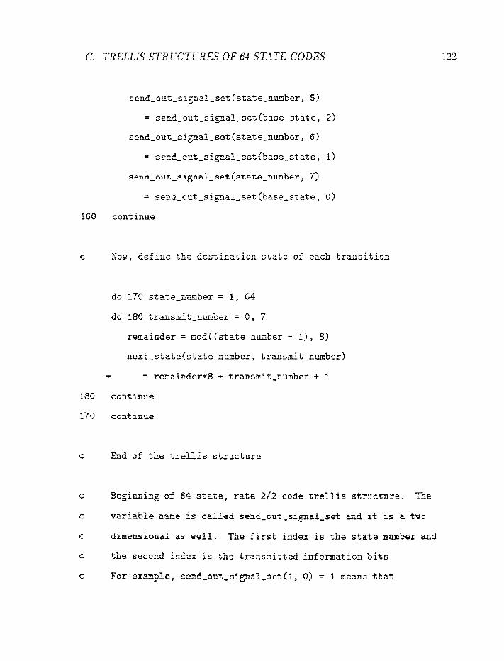
c Now, def ine the destination state of each trmsition
c End of the trellis strrrcture
c Beginning of 54 state, rate 212 code tref fis stntlcture. The
c variabfe a w e is czlfed send-out-sigaal-set a d it is a t m
c 85aensiccd zs sell. first index is the state n1mber and
c the second k B e x is the trzllsmitted infomat ion bits
c For e x a p i e , se~d-o~t,slpzL-set(l, 0) = 1 nems that
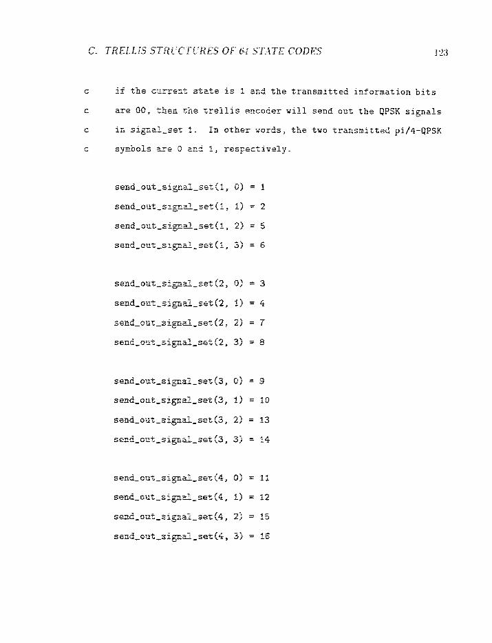

c use loops to generate the re s t of the t r e l l i s structure
do 100 s t a t e - ~ . ~ b e r = 5 , 8
base-state = state-number - 4
send-out-signal-set (state-number , 0)
= send-ozt-signal ,set (base-state, 1)
send,out-~ii;l iaI~set (state-number, 1)
= send-out-signal-set (base-state, 0)
send-oat-signal-set (state-number , 2)
= send-out-signal-set (base-state, 3)
send-cut-signal-set (state-number, 3)
= send-out,signal,set (base-state, 2)
100 cont ime
do 110 state-nmber = 9, 12
base-state = state-number - 8
secd,c\it,sipd-se.+,(state-number, 0)
= send-out-sipal,set(base,state, 2)
se~d-oat_sii;=~aP-set (stateenumber, 1)
= secd-ozt-sipd,set(5ase_state, 3)
send -o .~ t - s i p~ - se t~s t a t e~number , 2)
= send-out-signal-set (base-state, 0)
serrd,a'r;t,sigml_set (state-number, 3)
= send-oot-signal-set (base-state, 1)
110 rontinne
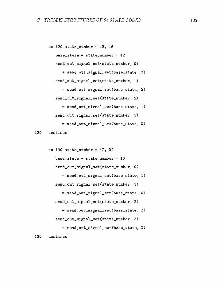
do 120 state-ember = 13, 16
base-stzte = s t a t e - n u b e r - 12
send-out-signal-set (state-number, 0)
= send-o.;t,signal-set (base-state, 3)
send-out-signal-set ( s t a t e -nube r , I)
= send-out-s ipal-set (base-stat e , 2)
send-out-signal-set (state-number , 2)
= seob-orit-signal-set (base-stat e , 1)
send-out-signal-set ( s t a t e-number , 3)
= send-out-signal-set (base-state, 0)
120 continue
do 130 state-number = 17, 32
base-state = state-number - 16
send-out-sigaaf-set (state-number, 0)
= send-out-signal-set (base-state, 1)
send-out-signal-set (state-number , 1)
= send-out-signal-set (base-state , 0)
send-out-signal-set (state-number , 2)
= send-out-signal-set (base-state, 3 )
send-out-signal-set [state-nwber , 3)
= send-out-s ipaf - se t {base-state, 2)
13C co;ltinlre
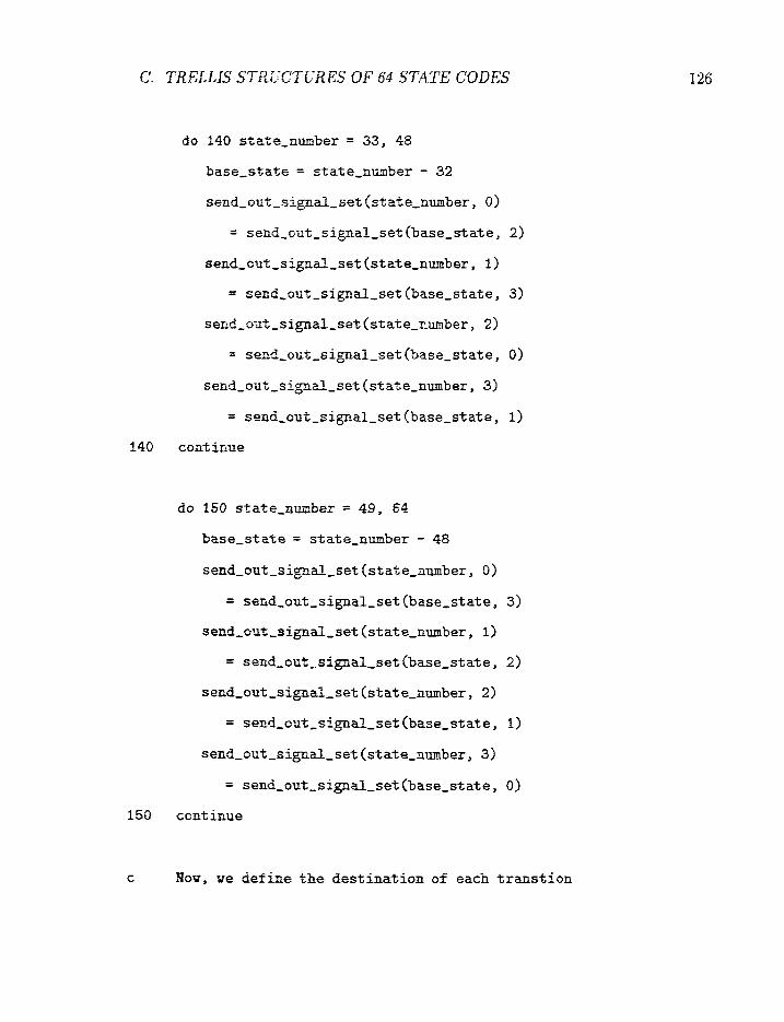
do 140 sttZo-n-mber = 33, 48
base-state = state-number - 32
send-oxt-sip&-set(sta2e-number, 0 )
= send-o~t-sipal-set(base-state, 2)
send,out,s4pdl,set (state-number, I)
= sezd-03%-sipal,set(base-state, 3)
send-ou t - s ipd - se t (stztexumber , 2)
= srad,oz%,sipal-set (base-stat e , 0)
send-oat-sipal-set (state-number, 3)
= seod-out-signal-set (base-state, 1)
140 continua
do 150 s ta te -nmber = 49, 84
bzse-stzte = s+,a+,e,o*x&er - 48
send-out-signal-set ( s t a t s-number , 0)
= send ,o :s+ , , s ip~-se t (base-state, 3)
send,oat;,sigsal.-set (state-number, 1)
= send-on";-sign&-setCbase-state, 2)
send-oat-s ipdl-set (state-number , 2)
= send-a~t-sip&-set(base-state, 1)
send-o~t-s ignal-set (state-number, 3)
= sem5,out-sipdl-set (base-st a t e , 0)
I50 continue
-- c ,Yo%, w e define the des t ina t ion of each t r a n s t i o n
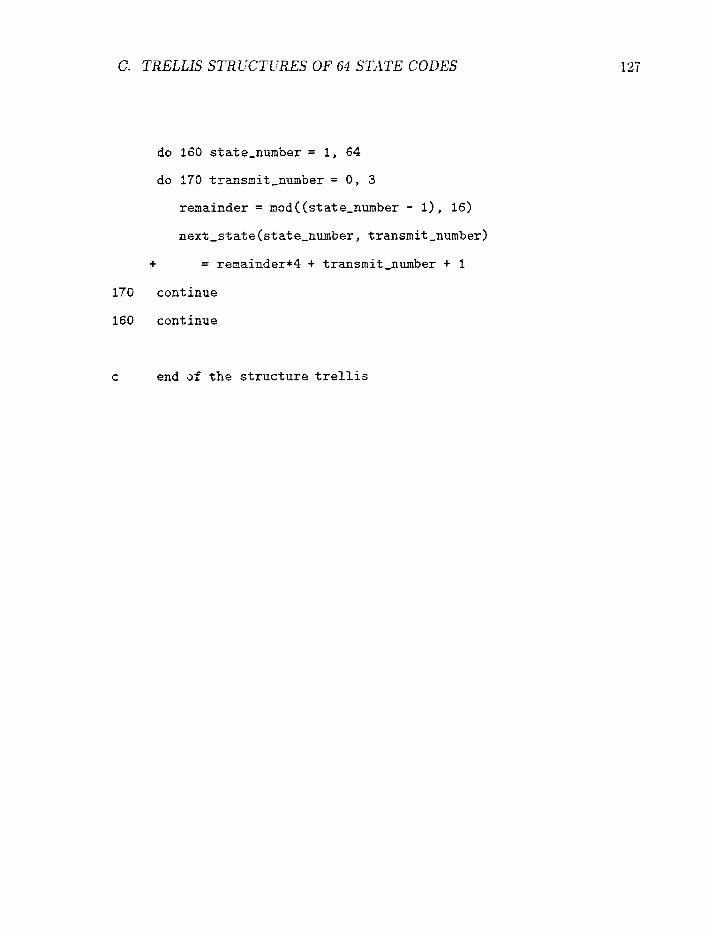
6. TRELLIS STRPCTLTRES OF 64 S r U E CODES
do 160 state-nwber = 1, 64
do I70 trmsnit-number = 0, 3
remaioder = nod((state,number - I), 16)
next-atate(state-nmber , transmit-number)
t = reaainder*4 + transmit-number + I
170 continue
160 continue
c end af the structure trellis

REFERENCES
[I] Mobile Communications - Developments and Reguiations, Proceedings of the 1984 International Conference.
[2] B.P.Lathi, Modern Digital and Analog Ccammunication Systems, HRW, Orlando, Florida, 1989
131 Electronic I~dusfn'es Association EIA, b'Cellular systemy', Report IS 54, De- cember 1989.
1.23 P.Melancon and J.Le.Be1, "A Characterization of the Frequency Selective Fading of the Mobile Radio Channel", IEEE Transactions on Vehicular Technology, Yo1 VT-35, ppl53-l6l, November 1986.
[5j S.kbshida, S.Onoe and F.Ikegami, "The effect of Sample Timing on Bit Error Rate Performance in a Multipath Fading Channel", IEEE Trans- actions on ifehieular Technology, Vol VT-35, pp.168-174, November 1986
[6] S.Yoshida and F.&egami, "A Comparison of Multipath Distortion Char- acteristics Among Digital Modulation Techniques", IEEE Transactions on Vehicular T~chnologg? Vof. VT-34, No.3, pp. 128-135, August 1985.
[7j d.hlazo, "Exact -Matched Filter Bound for 2-Beam Rayleigh Fading", in Proceedings, Globecorn 90, San Diego, pp.507A.l.1, December 1990.
181 F.D.Carber, and lf.B.Pursely, "Performance of Differentially Coherent Digital Communications over Frequency Selective Fading Channels", IEEE' Transacfions on Communicafions, Vol. COhilM-36 No.1, pp.21-31, January 1988.
P.X.Bdlo and B.C.-*.;din, ''The Effect of E'rzqcreacy Selecti-ve Fading or. - - the binary error probabilities of incoherent and differentially coherent matched filter receivers", IEEE Traiisctctions Commwtication System, Vol CS-I I, pp.lC&186? Jme 1963.

[lo] C.L.Liu acd K.Feher: "Bit E r r o r R a t e Per fo rmance of $-DQPSK in a Frequency Selective Fast Rayleigh Fading Channel", IEEK 7'rnnsnciions on Vehicular Technology, Vol. VT--10, No.3, pp.558-568, August 1991.
[ l l ] C.L.Liu and K.Feher, "Non-Coherent :-QPSK in a n AWGN-CCI Com- bined Interference Environment" , IEEE 3gth Vehicular Technology Co~zf~r- ence, San Francisco, C h , pp.83-94, May 1989.
f?2] G.Ungerboeck, "Channel C o d i n g w i t h Mu!t,i!eve!/Phase Signa!sW, iE1T;' Transactions on Information Theory, Vol. IT-28, pp. 55-66, J a~ iua ry 1982.
[13] P.J.McLane, P.H.Wittke, P.Ho and C.Loo, "The Per fo rmance of c Trellis Codes Mobi le Sate l l i te Communications", IEEE Transactions 0 1 1 Commu- nications, V01. COX~XJI-36, No.9, pp.1242-1246, TJov 1988.
[14] Edbauer Fraziz, "Performance of Interleaved Trellis-Coded Differential 8- PSK M o d u l a t i o n over Fading Channels", IEEE Journal on Selected Areas on Communications, Vol. SAC-7, it'o.9, pp.1340-1346, December 1989.
[15] S.Wilson, "Rate 5 f6 Trellis C o d e d 8-PSK", IEEE Eunsactions on Grnmu- nication, 'Crol.COM-34: 30.10, pp.1045-1049, October 1986.
[16j D.Divsalar and M.K.Simon, "The Design of Trellis C o d e d M P S K for Fad- ing Channels: Set Par t i t ion ing for O p t i m u m C o d e Design", IEEE ?i.ans- actions on Communications, Vol.COh1-36, pp.1013-1021, September 1988.
[17] D.Divsalar and M.Ii.Simon, "The Design of Trellis C o d e d M P S K for Fad- i n g Channels: Per fo rmance Criteria", IEEE Transactions on Comrnu~ticu- tions, Vol. Corn-36, pp.1004-1012, September 1988.
[la] D,Divsalar and &l.K.Simon, "Multiple Trell is C o d e d Modula t ion (MCTM) " , in Proceedings, IEEE Glo ba2 Telecommunication Conference, Tokyo, Japan, pp.43.8.1-43.8.6., Sovember 1987.
j19f D.Divsalar and 34.K.Simon, "Trellis-Coded Modula t ion for 4800-9600 bit/s Transmiss ion over a Fading Mobi le Sate l l i te Channel", IEEE J o ~ r - nal on Selected Areas on Communicaiions, Vol. SAC-5, 80.2, pp.162-175, Febu- rary 1987.
RO] D-Divsalar and M.K.Simon, "The Per fo rmance of Trellis C o d e s Multi level D P S K on a Fadir;g Mobi le Sate l l i te Channel , IEEE Transactionv on Ve- hicular TechnoIogy~ V01. VT-37, Ncr.2, pp.78-91, May 1988.
[2Ij R.McKay, "Error Bounds for Trellis Coded Modulation on Mobile Satel- lite ChannelsyE, ?rl.Sc(Eng.) Thesis, Dept. of Electrical Engineering, Queen's Gniversity, Kingston, Ontario, Canada.
/22f J-Ca-vers and P.Ho, "Analysis of the Error Performance of Trellis-Coded lWodulations in Rayleigh Fading Channel", IEEE Transactions 072 Com- m u n i c ~ f i o m ~ 'I'oLCOlI-4O3 pp.74-$3, January 1992.
[23] G.D.Forney, '%hxirnum-Likelihood Sequence Estimation of Digital Se- quences in the Presence of fntersymbol Interfencef', IEEE Transactions on Information Theom, ?"of. VT-18, No.3, pp.363-378, May 1912.
f24] W.Koch, mcf A-Baier, "Optimum and sub-Optimum Detection of Coded Data Disturbed by Time-Varying Intersymbol Interference", in Proceed- ings, Globecorn 9D7 Sao Diego, Dec. 1990, pp.507A.l.l.
j25] G.D.Forney, "Viterbi Algorithm", Proceedings of the IEEE, VoI.61(1973), il'o.3, pp.268-278.
1261 J.Hagenauer, "A Viterbi Algorithm with Soft-Decision Outputs and its Application", in Proceedin% IEEE Gfobecom '89? Dallas, Texas, Vo1.3, pp.47.1.1-47. I.?, Itlcts-ember 1989.
j2Tf P-Hoeher, "'TGlM on Frequency Selective Fading Channels: a Compar- ison of Soft-Output Probabilistic Equalizers", ia Proceedings, Globecorn 90, San Diego, pp.401.4.1-401.4.6, December 1990.
I281 M.Eyuboglu a d f.V.R.Qureshl, "Reduced-State Sequence Estimation with set-partitioning and decision feedback", IEEE Transactions on Corn- muncations, 3T~11CC031-36z pp.13-20: January 1988.
f291 J.B.Andersoo and S.SIohm; "Sequential Coding Algorithms: A survey and Cost analysis", IEIEE Transacfions on Communication, \ioI,C0kI-1-32, pp.169-176, Febufq- 138-4.
f301 S-JSimmons. "Breadth-Erst %&is Cecoding with Adaptive Effort7', IEEE ~r~rzsartfa'ons on Commtlncat-ions, t301.COM-38, pp.3-12, January 1990.
131j J.G.Proakis? Digitat Communications, McGraw Hiff, 1983.
[32] M.?pfoher arid J.T,odse, "TCMP - A Modulation a d Coding Strategy for Rician Fading Channelsff, fEEE Journals on Selected Areas in Communica- tions. 1990.
[33i 2-Cai-as, "--in Xnafysis of Pilot Symbol Assisted QPSK for Digi- tal Mobile Communications". in Proc~edings, Glabfcom '$0, San Diego, D D . ~ @ Y . X . ~ . ~ , s December f 990.
[34] P.Ho m d D.Fwg, CcError Probability of Trellis-Coded Modulations with Correlated Rayfeigh Fading", Fi,Pteenth Biennial Symposium on Conzrnutzi- catiolzs, Queezs Uni~ersit?;, Kings~on. Canada, pp. 1 f 6-1 4,!2, June 1990.
i35j L.F.i'v>i, "Treiiis-Coded Moduiation with iv3uitidimension,?I. Zonsteiia- tion'', IEEE Tmrtsacfions of ,fn$ormafion Theory, Vo1.R-33, pp.483-501, July iS57.
I354 G.D.Fctrner; Jr.,et ai., :'Efficient Modulation for Band Limited Channel", - IEEE Jcmrmi' on ~e!ecied -4 reas an f;'ornnzz~nicatiorts, I'olSAC-2, pp.632-647, Sept 1984.
f373 R.Fang and tY.Lee, 5gFour-Dimensionally Coded Systems for Combatting Effects of Severe fntersymbaf Interference and Co-channel Interfer- ence", in Pr~ceedP-rtgs: Gicthe5:om 85 pp.30.4.1-30.4.7., December 1983.
[3Sj C.J.Ga&sle. U.ShaE axid 'rgr,.K.Kennedj; "Treflis-Coded Modulation on Dig- ital Microwaw Radb Splstems - simulations for ,Multipath Fading ChannefV9 IEEE Transaclio?r oa C~mnzlnications, Vol.COL3-39, NO.^., pp.484- 495, Xpfil 1991.
1391 D=KK.P.E:,lngt aError f erformance of PSK Signals Transmitted Over Cor- refated Rayfeigh Fading Channels"', M.A.ScfEng.) Thesis, School of Engi- oeering Science, Simon Fraser University, Burnaby, B.C., Canada.