Embed Size (px)
Citation preview
SCIENCE CHINAPhysics, Mechanics & Astronomy p r i n t - c r o s s m a r k
February 2019 Vol. 62 No. 2: 029502https://doi.org/10.1007/s11433-018-9309-2
c⃝ Science China Press and Springer-Verlag GmbH Germany, part of Springer Nature 2018 phys.scichina.com link.springer.com
. Invited Review .Special Issue: The X-ray Timing and Polarimetry Frontier with eXTP
The enhanced X-ray Timing and Polarimetry mission—eXTP
ShuangNan Zhang1*, Andrea Santangelo1,2*, Marco Feroci3,4*, YuPeng Xu1*, FangJun Lu1,Yong Chen1, Hua Feng5, Shu Zhang1, Søren Brandt36, Margarita Hernanz12,13, Luca Baldini33,
Enrico Bozzo6, Riccardo Campana23, Alessandra De Rosa3, YongWei Dong1, Yuri Evangelista3,4,Vladimir Karas8, Norbert Meidinger16, Aline Meuris10, Kirpal Nandra16, Teng Pan21, Giovanni Pareschi31,
Piotr Orleanski37, QiuShi Huang22, Stephane Schanne10, Giorgia Sironi31, Daniele Spiga31,Jiri Svoboda8, Gianpiero Tagliaferri31, Christoph Tenzer2, Andrea Vacchi25,26, Silvia Zane14,
Dave Walton14, ZhanShan Wang22, Berend Winter14, Xin Wu7, Jean J. M. in ’t Zand11,Mahdi Ahangarianabhari29, Giovanni Ambrosi32, Filippo Ambrosino3, Marco Barbera35, Stefano Basso31,
Jorg Bayer2, Ronaldo Bellazzini33, Pierluigi Bellutti28, Bruna Bertucci32, Giuseppe Bertuccio29,Giacomo Borghi28, XueLei Cao1, Franck Cadoux7, Riccardo Campana23, Francesco Ceraudo3,
TianXiang Chen1, YuPeng Chen1, Jerome Chevenez36, Marta Civitani31, Wei Cui25, WeiWei Cui1,Thomas Dauser39, Ettore Del Monte3,4, Sergio Di Cosimo1, Sebastian Diebold2, Victor Doroshenko2,
Michal Dovciak8, YuanYuan Du1, Lorenzo Ducci2, QingMei Fan21, Yannick Favre7,Fabio Fuschino23, Jose Luis Galvez12,13, Min Gao1, MingYu Ge1, Olivier Gevin10,
Marco Grassi30, QuanYing Gu21, YuDong Gu1, DaWei Han1, Bin Hong21, Wei Hu1,Long Ji2, ShuMei Jia1, WeiChun Jiang1, Thomas Kennedy14, Ingo Kreykenbohm39, Irfan Kuvvetli36,
Claudio Labanti23, Luca Latronico34, Gang Li1, MaoShun Li1, Xian Li1, Wei Li1,ZhengWei Li1, Olivier Limousin10, HongWei Liu1, XiaoJing Liu1, Bo Lu1, Tao Luo1,
Daniele Macera29, Piero Malcovati30, Adrian Martindale15, Malgorzata Michalska37, Bin Meng1,Massimo Minuti33, Alfredo Morbidini3, Fabio Muleri3,4, Stephane Paltani6, Emanuele Perinati2,
Antonino Picciotto28, Claudio Piemonte28, JinLu Qu1, Alexandre Rachevski24, Irina Rashevskaya27,Jerome Rodriguez10, Thomas Schanz2, ZhengXiang Shen22, LiZhi Sheng20, JiangBo Song21,
LiMing Song1, Carmelo Sgro33, Liang Sun1, Ying Tan1, Phil Uttley9,Bo Wang17, DianLong Wang19, GuoFeng Wang1, Juan Wang1, LangPing Wang18,
YuSa Wang1, Anna L. Watts9, XiangYang Wen1, Jorn Wilms39, ShaoLin Xiong1, JiaWei Yang1,Sheng Yang1, YanJi Yang1, Nian Yu1, WenDa Zhang8, Gianluigi Zampa24,
Nicola Zampa24, Andrzej A. Zdziarski38, AiMei Zhang1, ChengMo Zhang1, Fan Zhang1, Long Zhang21,Tong Zhang1, Yi Zhang1, XiaoLi Zhang21, ZiLiang Zhang1, BaoSheng Zhao20,
ShiJie Zheng1, YuPeng Zhou21, Nicola Zorzi28, and J. Frans Zwart11
*Corresponding authors (ShuangNan Zhang, email: [email protected]; Andrea Santangelo, email: [email protected]; Marco Feroci,email: [email protected]; YuPeng Xu, email: [email protected])
S. N. Zhang, et al. Sci. China-Phys. Mech. Astron. February (2019) Vol. 62 No. 2 029502-2
1 Key Laboratory for Particle Astrophysics, Institute of High Energy Physics, Chinese Academy of Sciences, Beijing 100049, China;2 Institut fur Astronomie und Astrophysik, Eberhard Karls Universitat, Tubingen 72076, Germany;
3 INAF – Istituto di Astrofisica e Planetologia Spaziali, Via Fosso del Cavaliere 100, Roma I-00133, Italy;4 INFN – Roma Tor Vergata, Via della Ricerca Scientifica 1, Roma I-00133, Italy;
5 Department of Engineering Physics and Center for Astrophysics, Tsinghua University, Beijing 100084, China;6 Department of Astronomy, University of Geneva, chemin d’Ecogia 16, Versoix 1290, Switzerland;
7 Department of Nuclear and Particle Physics, University of Geneva, Geneva CH-1211, Switzerland;8 Astronomical Institute, Czech Academy of Sciences, Prague 14100, Czech Republic;
9 Anton Pannekoek Institute for Astronomy, University of Amsterdam, Amsterdam 1098 XH, The Netherlands;10 CEA Paris-Saclay/IRFU, F-91191 Gif sur Yvette, France;
11 SRON Netherlands Institute for Space Research, Sorbonnelaan 2, Utrecht 3584 CA, The Netherlands;12 Institute of Space Sciences (ICE, CSIC), 08193 Cerdanyola del Valles (Barcelona), Spain;
13 Institut d’Estudis Espacials de Catalunya (IEEC), Barcelona 08034, Spain;14 Mullard Space Science Laboratory, University College London, Holmbury St Mary, Dorking, Surrey RH56NT, UK;
15 Department of Physics and Astronomy, University of Leicester, Leicester LE17RH, UK;16 Max Planck Institute for Extraterrestrial Physics, Giessenbachstr. 1, Garching 85748, Germany;
17 Center for Precision Engineering, Harbin Institute of Technology, Harbin 150001, China;18 State Key Laboratory of Advanced Welding and Joining, Harbin Institute of Technology, Harbin 150006, China;
19 School of Chemistry and Chemical Engineering, Harbin Institute of Technology, Harbin 150001, China;20 State Key Laboratory of Transient Optics and Photonics, Xi’an Institute of Optics and Precision Mechanics, Chinese Academy of Sciences,
Xi’an 710119, China;21 Beijing Institute of Spacecraft System Engineering, CAST, Beijing 100094, China;
22 Key Laboratory of Advanced Material Microstructure of Education Ministry of China, Institute of Precision Optical Engineering,School of Physics Science and Engineering, Tongji University, Shanghai 200090, China;
23 Osservatorio di Astrofisica e Scienza Dello Spazio di Bologna, Istituto Nazionale di Astofisica, Bologna 40129, Italy;24 Sezione di Trieste, Istituto Nazionale di Fisica Nucleare, Trieste TS 34149, Italy;
25 Department of Physics and Center for Astrophysics, Tsinghua University, Beijing 100084, China;26 Universita’ degli Studi di Udine, Via delle Scienze 206, Udine 33100, Italy;
27 TIFPA, Istituto Nazionale di Fisica Nucleare, Via Sommarive 14, Povo TN 38123, Italy;28 Fondazione Bruno Kessler, Via Sommarive 18, Povo TN 38123, Italy;
29 Politecnico di Milano, Via Anzani 42, Como, Italy;30 University of Pavia, Department of Electronics, Information and Biomedical Engineering and INFN Pavia, Via Ferrata 3,
Pavia I-27100, Italy;31 Osservatorio Astronomico di Brera, Istituto Nazionale di Astofisica, Via Brera, 28, Milano 20121, Italy;
32 Sezione di Perugia, Istituto Nazionale di Fisica Nucleare, Via Alessandro Pascoli, 23c, Perugia 06123, Italy;33 Sezione di Pisa, Istituto Nazionale di Fisica Nucleare, Largo Bruno Pontecorvo, 3, Pisa 56127, Italy;
34 Sezione di Torino, Istituto Nazionale di Fisica Nucleare, Via Pietro Giuria, 1, Torino 10125, Italy;35 Dipartimento di Fisica e Chimica, Via Archirafi 36, Palermo 90123, Italy;
36 DTU, Building 327, DK-2800 Kongens, Lyngby, Denmark;37 Space Research Center, Polish Academy of Sciences, Bartycka 18a, Warszawa PL-00-716, Poland;
38 Nicolaus Copernicus Astronomical Center, Polish Academy of Sciences, Bartycka 18, Warszawa PL-00-716, Poland;39 Dr. Karl Remeis-Observatory and Erlangen Centre for Astroparticle Physics, Universitat Erlangen-Nurnberg, Sternwartstr. 7,
Bamberg D-96049, Germany
Received September 25, 2018; accepted September 30, 2018; published online December 7, 2018
In this paper we present the enhanced X-ray Timing and Polarimetry mission—eXTP. eXTP is a space science mission designedto study fundamental physics under extreme conditions of density, gravity and magnetism. The mission aims at determiningthe equation of state of matter at supra-nuclear density, measuring effects of QED, and understanding the dynamics of matter instrong-field gravity. In addition to investigating fundamental physics, eXTP will be a very powerful observatory for astrophysicsthat will provide observations of unprecedented quality on a variety of galactic and extragalactic objects. In particular, its widefield monitoring capabilities will be highly instrumental to detect the electro-magnetic counterparts of gravitational wave sources.The paper provides a detailed description of: (1) the technological and technical aspects, and the expected performance of theinstruments of the scientific payload; (2) the elements and functions of the mission, from the spacecraft to the ground segment.
X-ray instrumentation, X-ray polarimetry, X-ray timing, space mission: eXTP
PACS number(s): 95.55.Ka, 95.85.Nv, 95.75.Hi, 97.60.Jd, 97.60.Lf
S. N. Zhang, et al. Sci. China-Phys. Mech. Astron. February (2019) Vol. 62 No. 2 029502-3
Citation: S. N. Zhang, A. Santangelo, M. Feroci, Y. P. Xu, F. J. Lu, Y. Chen, H. Feng, S. Zhang, S. Brandt, M. Hernanz, L. Baldini, E. Bozzo, R. Campana,A. De Rosa, Y. W. Dong, Y. Evangelista, V. Karas, N. Meidinger, A. Meuris, K. Nandra, T. Pan, G. Pareschi, P. Orleanski, Q. S. Huang, S. Schanne,G. Sironi, D. Spiga, J. Svoboda, G. Tagliaferri, C. Tenzer, A. Vacchi, S. Zane, D. Walton, Z. S. Wang, B. Winter, X. Wu, J. J. M. in ’t Zand, M.Ahangarianabhari, G. Ambrosi, F. Ambrosino, M. Barbera, S. Basso, J. Bayer, R. Bellazzini, P. Bellutti, B. Bertucci, G. Bertuccio, G. Borghi, X.L. Cao, F. Cadoux, R. Campana, F. Ceraudo, T. X. Chen, Y. P. Chen, J. Chevenez, M. Civitani, W. Cui, W. W. Cui, T. Dauser, E. Del Monte, S. DiCosimo, S. Diebold, V. Doroshenko, M. Dovciak, Y. Y. Du, L. Ducci, Q. M. Fan, Y. Favre, F. Fuschino, J. L. Galvez, M. Gao, M. Y. Ge, O. Gevin,M. Grassi, Q. Y. Gu, Y. D. Gu, D. W. Han, B. Hong, W. Hu, L. Ji, S. M. Jia, W. C. Jiang, T. Kennedy, I. Kreykenbohm, I. Kuvvetli, C. Labanti, L.Latronico, G. Li, M. S. Li, X. Li, W. Li, Z. W. Li, O. Limousin, H. W. Liu, X. J. Liu, B. Lu, T. Luo, D. Macera, P. Malcovati, A. Martindale, M.Michalska, B. Meng, M. Minuti, A. Morbidini, F. Muleri, S. Paltani, E. Perinati, A. Picciotto, C. Piemonte, J. L. Qu, A. Rachevski, I. Rashevskaya,J. Rodriguez, T. Schanz, Z. X. Shen, L. Z. Sheng, J. B. Song, L. M. Song, C. Sgro, L. Sun, Y. Tan, P. Uttley, B. Wang, D. L. Wang, G. F. Wang, J.Wang, L. P. Wang, Y. S. Wang, A. L. Watts, X. Y. Wen, J. Wilms, S. L. Xiong, J. W. Yang, S. Yang, Y. J. Yang, N. Yu, W. D. Zhang, G. Zampa, N.Zampa, A. A. Zdziarski, A. M. Zhang, C. M. Zhang, F. Zhang, L. Zhang, T. Zhang, Y. Zhang, X. L. Zhang, Z. L. Zhang, B. S. Zhao, S. J. Zheng, Y.P. Zhou, N. Zorzi, and J. F. Zwart, The enhanced X-ray Timing and Polarimetry mission—eXTP, Sci. China-Phys. Mech. Astron. 62, 029502 (2019),https://doi.org/10.1007/s11433-018-9309-2
Contents
1 Introduction 029502-4
2 The scientific payload 029502-4
2.1 Spectroscopic focusing array (SFA) . . . . . . . . . . . . . . . . . . . . . . . . . . . . . . . . . . . . . . . . . . . . . . . . . . . . . . . . . . 029502-4
2.1.1 Optics . . . . . . . . . . . . . . . . . . . . . . . . . . . . . . . . . . . . . . . . . . . . . . . . . . . . . . . . . . . . . . . . . . . . . . . . . . . . . 029502-5
2.1.2 SFA detectors and electronics . . . . . . . . . . . . . . . . . . . . . . . . . . . . . . . . . . . . . . . . . . . . . . . . . . . . . . . . 029502-7
2.1.3 The filter wheel and cooling . . . . . . . . . . . . . . . . . . . . . . . . . . . . . . . . . . . . . . . . . . . . . . . . . . . . . . . . . 029502-7
2.1.4 Performance: Effective area and background . . . . . . . . . . . . . . . . . . . . . . . . . . . . . . . . . . . . . . . . . . 029502-8
2.2 Large area detector (LAD) . . . . . . . . . . . . . . . . . . . . . . . . . . . . . . . . . . . . . . . . . . . . . . . . . . . . . . . . . . . . . . . . . . 029502-8
2.2.1 The LAD architecture . . . . . . . . . . . . . . . . . . . . . . . . . . . . . . . . . . . . . . . . . . . . . . . . . . . . . . . . . . . . . . . 029502-8
2.2.2 Detectors and electronics . . . . . . . . . . . . . . . . . . . . . . . . . . . . . . . . . . . . . . . . . . . . . . . . . . . . . . . . . . . . 029502-9
2.2.3 Collimators, filters . . . . . . . . . . . . . . . . . . . . . . . . . . . . . . . . . . . . . . . . . . . . . . . . . . . . . . . . . . . . . . . . . 029502-11
2.2.4 Performance: Area and background . . . . . . . . . . . . . . . . . . . . . . . . . . . . . . . . . . . . . . . . . . . . . . . . . 029502-11
2.3 Polarimetry focusing array (PFA) . . . . . . . . . . . . . . . . . . . . . . . . . . . . . . . . . . . . . . . . . . . . . . . . . . . . . . . . . . 029502-12
2.3.1 Detectors and electronics. . . . . . . . . . . . . . . . . . . . . . . . . . . . . . . . . . . . . . . . . . . . . . . . . . . . . . . . . . . 029502-12
2.3.2 Performance: Area, background, MDP . . . . . . . . . . . . . . . . . . . . . . . . . . . . . . . . . . . . . . . . . . . . . . 029502-13
2.4 Wide field monitor (WFM) . . . . . . . . . . . . . . . . . . . . . . . . . . . . . . . . . . . . . . . . . . . . . . . . . . . . . . . . . . . . . . . . 029502-15
2.4.1 The WFM architecture . . . . . . . . . . . . . . . . . . . . . . . . . . . . . . . . . . . . . . . . . . . . . . . . . . . . . . . . . . . . . 029502-16
2.4.2 Performance . . . . . . . . . . . . . . . . . . . . . . . . . . . . . . . . . . . . . . . . . . . . . . . . . . . . . . . . . . . . . . . . . . . . . . 029502-17
3 The mission profile 029502-18
3.1 The spacecraft . . . . . . . . . . . . . . . . . . . . . . . . . . . . . . . . . . . . . . . . . . . . . . . . . . . . . . . . . . . . . . . . . . . . . . . . . . . . 029502-18
3.2 Launch and orbit . . . . . . . . . . . . . . . . . . . . . . . . . . . . . . . . . . . . . . . . . . . . . . . . . . . . . . . . . . . . . . . . . . . . . . . . . 029502-19
3.3 The ground segment . . . . . . . . . . . . . . . . . . . . . . . . . . . . . . . . . . . . . . . . . . . . . . . . . . . . . . . . . . . . . . . . . . . . . . 029502-20
4 Observing strategy 029502-21
5 Conclusions 029502-21
S. N. Zhang, et al. Sci. China-Phys. Mech. Astron. February (2019) Vol. 62 No. 2 029502-4
1 Introduction
The enhanced X-ray Timing and Polarimetry mission—eXTPis a scientific space mission designed to study the state ofmatter under extreme conditions of density, gravity and mag-netism [1]. Primary goals are the determination of the equa-tion of state of matter at supra-nuclear density, the measure-ment of QED effects in the radiation emerging from highlymagnetized stars, and the study of matter dynamics in thestrong-field regime of gravity. The matter inside neutronstars (NSs), the space-time close to black holes (BHs), andthe extremely magnetized vacuum close to magnetars areamong the uncharted territories of fundamental physics. TheeXTP mission will revolutionize these areas of fundamen-tal research by high precision X-ray measurements of NSsacross the magnetic field scale and BHs across the mass scale.In addition to investigating fundamental physics, eXTP willbe a very powerful observatory for astrophysics, which willprovide observations of unprecedented quality on a variety ofgalactic and extragalactic objects. In particular, its wide fieldmonitoring capabilities will be highly instrumental in identi-fying the electro-magnetic counterparts of gravitational wavesources.
The eXTP science case is described in four papers address-ing the three main science objectives of the mission and theobservatory science [2-5]. They are included in this specialissue.
The eXTP mission is an enhanced version of the Chi-nese X-ray Timing and Polarimetry mission [6], which in2011 was selected and funded for a Phase 0/A study as oneof the background concept missions in the Strategic Prior-ity Space Science Program of the Chinese Academy of Sci-ences (CAS). Also in 2011, the Large Observatory for Tim-ing (LOFT) mission concept [7, 8] was selected for an as-sessment study in the context of the ESA’s Announcement ofOpportunity for the third of the medium size missions (M3)foreseen in the framework of the Agency’s Cosmic Visionprogramme. The LOFT study was carried out in 2011-2014by a consortium of European institutes. Eventually the exo-planetary mission PLATO, considered more well-timed, wasselected as ESA’s Cosmic Vision M3 mission. Followingthis, in 2015, the European LOFT consortium and the Chi-nese team merged the LOFT and XTP mission concepts, thusstarting the eXTP project.
The eXTP international consortium is led by the Instituteof High Energy Physics (IHEP) of CAS, and includes othermajor institutions of CAS, several Chinese Universities, andinstitutions from ten European countries. Other internationalpartners participate in eXTP as well. Overall more than 200scientists in over 100 institutions from about 20 countries aremembers of the consortium. The mission has recently started
an extended phase A study that is expected to be completedby the end of 2018 in view of a launch around 2025.
In this paper we present the technological and technical as-pects, and the expected performance of the instruments of thescientific payload, as well as the main elements and functionsof the mission.
2 The scientific payload
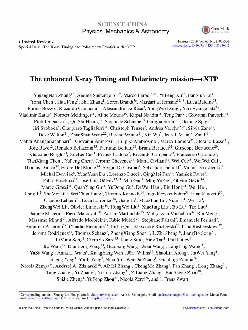
An artistic view of the current design of the eXTP satelliteis shown in Figure 1. The scientific payload of the missionconsists of four main instruments: the spectroscopic focusingarray (SFA, sect. 2.1), the large area detector (LAD, sect. 2.2),the polarimetry focusing array (PFA, sect. 2.3), and the widefield monitor (WFM, sect. 2.4).
2.1 Spectroscopic focusing array (SFA)
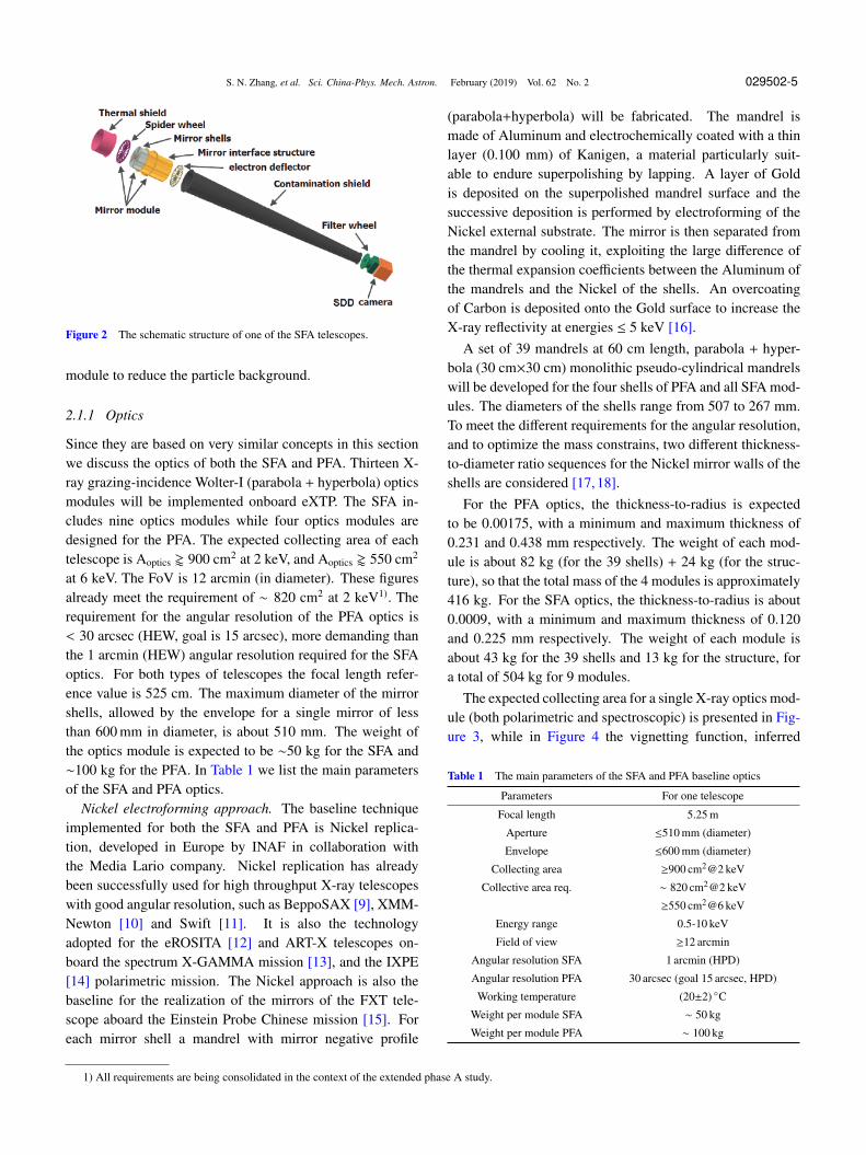
The SFA consists of an array of 9 identical Wolter-I grazing-incidence X-ray telescopes, and is mainly used for spectraland timing observations in the energy range 0.5-10 keV. Eachtelescope consists of the thermal shield, the mirror module,the electron deflector, the filter wheel, and the focal planecamera. A schematic view of one of the SFA telescopes isshown in Figure 2. The SFA total effective area is expectedto be larger than ∼ 7400 cm2 at 2 keV, and the field of view(FoV) is 12 arcmin in diameter. The SFA uses silicon driftdetectors (SDDs) as focal plane detectors. Each telescope in-cludes a 19-cell SDD array, whose energy resolution is lessthan 180 eV at 6 keV. The time resolution is 10µs, and thedead time is expected to be less than 5% at 1 Crab. The angu-lar resolution is required to be less than 1 arcmin (HEW). Tomeet the requirements, the working temperature of the mir-ror modules has to be stable at (20±2) ◦C. A thermal shieldis introduced to keep the temperature as steady as possible.An electron deflector is installed at the bottom of the mirror
SFA
PFA
LAD
WFM
LAD
PFA
WFM
SFA
Figure 1 Artistic view of the eXTP satellite. The science payload consistsof four instruments: the focused SFA and PFA telescopes arrays, the largearea instrument LAD, and the WFM to monitor a large fraction of the sky.
S. N. Zhang, et al. Sci. China-Phys. Mech. Astron. February (2019) Vol. 62 No. 2 029502-5
Figure 2 The schematic structure of one of the SFA telescopes.
module to reduce the particle background.
2.1.1 Optics
Since they are based on very similar concepts in this sectionwe discuss the optics of both the SFA and PFA. Thirteen X-ray grazing-incidence Wolter-I (parabola + hyperbola) opticsmodules will be implemented onboard eXTP. The SFA in-cludes nine optics modules while four optics modules aredesigned for the PFA. The expected collecting area of eachtelescope is Aoptics ' 900 cm2 at 2 keV, and Aoptics ' 550 cm2
at 6 keV. The FoV is 12 arcmin (in diameter). These figuresalready meet the requirement of ∼ 820 cm2 at 2 keV1). Therequirement for the angular resolution of the PFA optics is< 30 arcsec (HEW, goal is 15 arcsec), more demanding thanthe 1 arcmin (HEW) angular resolution required for the SFAoptics. For both types of telescopes the focal length refer-ence value is 525 cm. The maximum diameter of the mirrorshells, allowed by the envelope for a single mirror of lessthan 600 mm in diameter, is about 510 mm. The weight ofthe optics module is expected to be ∼50 kg for the SFA and∼100 kg for the PFA. In Table 1 we list the main parametersof the SFA and PFA optics.
Nickel electroforming approach. The baseline techniqueimplemented for both the SFA and PFA is Nickel replica-tion, developed in Europe by INAF in collaboration withthe Media Lario company. Nickel replication has alreadybeen successfully used for high throughput X-ray telescopeswith good angular resolution, such as BeppoSAX [9], XMM-Newton [10] and Swift [11]. It is also the technologyadopted for the eROSITA [12] and ART-X telescopes on-board the spectrum X-GAMMA mission [13], and the IXPE[14] polarimetric mission. The Nickel approach is also thebaseline for the realization of the mirrors of the FXT tele-scope aboard the Einstein Probe Chinese mission [15]. Foreach mirror shell a mandrel with mirror negative profile
(parabola+hyperbola) will be fabricated. The mandrel ismade of Aluminum and electrochemically coated with a thinlayer (0.100 mm) of Kanigen, a material particularly suit-able to endure superpolishing by lapping. A layer of Goldis deposited on the superpolished mandrel surface and thesuccessive deposition is performed by electroforming of theNickel external substrate. The mirror is then separated fromthe mandrel by cooling it, exploiting the large difference ofthe thermal expansion coefficients between the Aluminum ofthe mandrels and the Nickel of the shells. An overcoatingof Carbon is deposited onto the Gold surface to increase theX-ray reflectivity at energies ≤ 5 keV [16].
A set of 39 mandrels at 60 cm length, parabola + hyper-bola (30 cm×30 cm) monolithic pseudo-cylindrical mandrelswill be developed for the four shells of PFA and all SFA mod-ules. The diameters of the shells range from 507 to 267 mm.To meet the different requirements for the angular resolution,and to optimize the mass constrains, two different thickness-to-diameter ratio sequences for the Nickel mirror walls of theshells are considered [17, 18].
For the PFA optics, the thickness-to-radius is expectedto be 0.00175, with a minimum and maximum thickness of0.231 and 0.438 mm respectively. The weight of each mod-ule is about 82 kg (for the 39 shells) + 24 kg (for the struc-ture), so that the total mass of the 4 modules is approximately416 kg. For the SFA optics, the thickness-to-radius is about0.0009, with a minimum and maximum thickness of 0.120and 0.225 mm respectively. The weight of each module isabout 43 kg for the 39 shells and 13 kg for the structure, fora total of 504 kg for 9 modules.
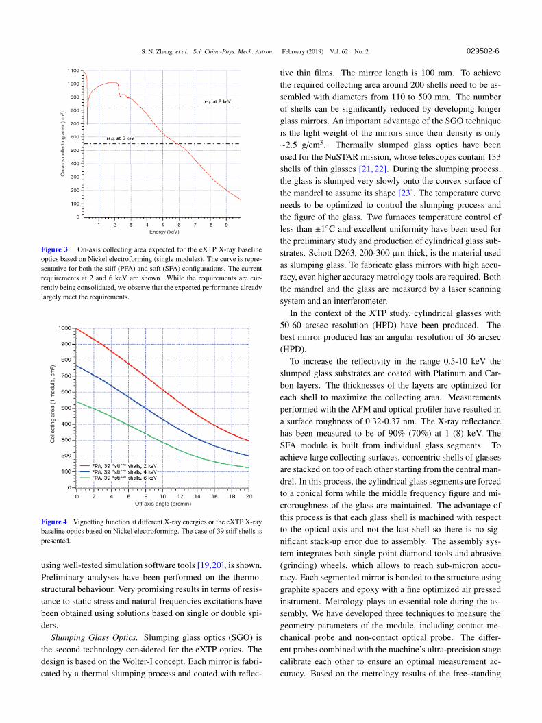
The expected collecting area for a single X-ray optics mod-ule (both polarimetric and spectroscopic) is presented in Fig-ure 3, while in Figure 4 the vignetting function, inferred
Table 1 The main parameters of the SFA and PFA baseline optics
Parameters For one telescope
Focal length 5.25 m
Aperture ≤510 mm (diameter)
Envelope ≤600 mm (diameter)
Collecting area ≥900 cm2@2 keV
Collective area req. ∼ 820 cm2@2 keV
≥550 cm2@6 keV
Energy range 0.5-10 keV
Field of view ≥12 arcmin
Angular resolution SFA 1 arcmin (HPD)
Angular resolution PFA 30 arcsec (goal 15 arcsec, HPD)
Working temperature (20±2) ◦C
Weight per module SFA ∼ 50 kg
Weight per module PFA ∼ 100 kg
1) All requirements are being consolidated in the context of the extended phase A study.
S. N. Zhang, et al. Sci. China-Phys. Mech. Astron. February (2019) Vol. 62 No. 2 029502-6O
n-a
xis
collecting a
rea (
cm
2)
Energy (keV)
Figure 3 On-axis collecting area expected for the eXTP X-ray baselineoptics based on Nickel electroforming (single modules). The curve is repre-sentative for both the stiff (PFA) and soft (SFA) configurations. The currentrequirements at 2 and 6 keV are shown. While the requirements are cur-rently being consolidated, we observe that the expected performance alreadylargely meet the requirements.
Co
lle
ctin
g a
rea
(1
mo
du
le,
cm
2)
Off-axis angle (arcmin)
Figure 4 Vignetting function at different X-ray energies or the eXTP X-raybaseline optics based on Nickel electroforming. The case of 39 stiff shells ispresented.
using well-tested simulation software tools [19,20], is shown.Preliminary analyses have been performed on the thermo-structural behaviour. Very promising results in terms of resis-tance to static stress and natural frequencies excitations havebeen obtained using solutions based on single or double spi-ders.
Slumping Glass Optics. Slumping glass optics (SGO) isthe second technology considered for the eXTP optics. Thedesign is based on the Wolter-I concept. Each mirror is fabri-cated by a thermal slumping process and coated with reflec-
tive thin films. The mirror length is 100 mm. To achievethe required collecting area around 200 shells need to be as-sembled with diameters from 110 to 500 mm. The numberof shells can be significantly reduced by developing longerglass mirrors. An important advantage of the SGO techniqueis the light weight of the mirrors since their density is only∼2.5 g/cm3. Thermally slumped glass optics have beenused for the NuSTAR mission, whose telescopes contain 133shells of thin glasses [21, 22]. During the slumping process,the glass is slumped very slowly onto the convex surface ofthe mandrel to assume its shape [23]. The temperature curveneeds to be optimized to control the slumping process andthe figure of the glass. Two furnaces temperature control ofless than ±1◦C and excellent uniformity have been used forthe preliminary study and production of cylindrical glass sub-strates. Schott D263, 200-300 µm thick, is the material usedas slumping glass. To fabricate glass mirrors with high accu-racy, even higher accuracy metrology tools are required. Boththe mandrel and the glass are measured by a laser scanningsystem and an interferometer.
In the context of the XTP study, cylindrical glasses with50-60 arcsec resolution (HPD) have been produced. Thebest mirror produced has an angular resolution of 36 arcsec(HPD).
To increase the reflectivity in the range 0.5-10 keV theslumped glass substrates are coated with Platinum and Car-bon layers. The thicknesses of the layers are optimized foreach shell to maximize the collecting area. Measurementsperformed with the AFM and optical profiler have resulted ina surface roughness of 0.32-0.37 nm. The X-ray reflectancehas been measured to be of 90% (70%) at 1 (8) keV. TheSFA module is built from individual glass segments. Toachieve large collecting surfaces, concentric shells of glassesare stacked on top of each other starting from the central man-drel. In this process, the cylindrical glass segments are forcedto a conical form while the middle frequency figure and mi-croroughness of the glass are maintained. The advantage ofthis process is that each glass shell is machined with respectto the optical axis and not the last shell so there is no sig-nificant stack-up error due to assembly. The assembly sys-tem integrates both single point diamond tools and abrasive(grinding) wheels, which allows to reach sub-micron accu-racy. Each segmented mirror is bonded to the structure usinggraphite spacers and epoxy with a fine optimized air pressedinstrument. Metrology plays an essential role during the as-sembly. We have developed three techniques to measure thegeometry parameters of the module, including contact me-chanical probe and non-contact optical probe. The differ-ent probes combined with the machine’s ultra-precision stagecalibrate each other to ensure an optimal measurement ac-curacy. Based on the metrology results of the free-standing
S. N. Zhang, et al. Sci. China-Phys. Mech. Astron. February (2019) Vol. 62 No. 2 029502-7
mirrors and after assembly, the impact of assembly error onthe angular resolution is controlled within 1 arcmin. Proto-types of the SFA optics have been developed by the TongjiUniversity, China. The 1st complete shell prototype has a fo-cal length of 4 m and 5 shells, with the outer shell diameter of170 mm as shown in Figure 5. Sixty shells coated with a Plat-inum have been assembled. The prototype has been tested atthe National Astronomical Observatory of China. The HPDof the spot has been estimated to be 3 arcmin at 2-8 keV. Theangular resolution of a complete shell prototype is estimatedto be ∼1.5 arcmin.
2.1.2 SFA detectors and electronics
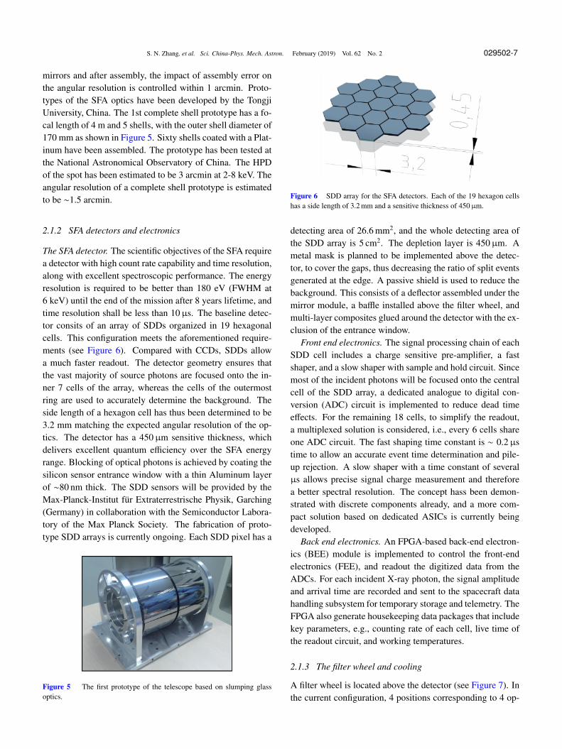
The SFA detector. The scientific objectives of the SFA requirea detector with high count rate capability and time resolution,along with excellent spectroscopic performance. The energyresolution is required to be better than 180 eV (FWHM at6 keV) until the end of the mission after 8 years lifetime, andtime resolution shall be less than 10µs. The baseline detec-tor consits of an array of SDDs organized in 19 hexagonalcells. This configuration meets the aforementioned require-ments (see Figure 6). Compared with CCDs, SDDs allowa much faster readout. The detector geometry ensures thatthe vast majority of source photons are focused onto the in-ner 7 cells of the array, whereas the cells of the outermostring are used to accurately determine the background. Theside length of a hexagon cell has thus been determined to be3.2 mm matching the expected angular resolution of the op-tics. The detector has a 450µm sensitive thickness, whichdelivers excellent quantum efficiency over the SFA energyrange. Blocking of optical photons is achieved by coating thesilicon sensor entrance window with a thin Aluminum layerof ∼80 nm thick. The SDD sensors will be provided by theMax-Planck-Institut fur Extraterrestrische Physik, Garching(Germany) in collaboration with the Semiconductor Labora-tory of the Max Planck Society. The fabrication of proto-type SDD arrays is currently ongoing. Each SDD pixel has a
Figure 5 The first prototype of the telescope based on slumping glassoptics.
Figure 6 SDD array for the SFA detectors. Each of the 19 hexagon cellshas a side length of 3.2 mm and a sensitive thickness of 450µm.
detecting area of 26.6 mm2, and the whole detecting area ofthe SDD array is 5 cm2. The depletion layer is 450µm. Ametal mask is planned to be implemented above the detec-tor, to cover the gaps, thus decreasing the ratio of split eventsgenerated at the edge. A passive shield is used to reduce thebackground. This consists of a deflector assembled under themirror module, a baffle installed above the filter wheel, andmulti-layer composites glued around the detector with the ex-clusion of the entrance window.
Front end electronics. The signal processing chain of eachSDD cell includes a charge sensitive pre-amplifier, a fastshaper, and a slow shaper with sample and hold circuit. Sincemost of the incident photons will be focused onto the centralcell of the SDD array, a dedicated analogue to digital con-version (ADC) circuit is implemented to reduce dead timeeffects. For the remaining 18 cells, to simplify the readout,a multiplexed solution is considered, i.e., every 6 cells shareone ADC circuit. The fast shaping time constant is ∼ 0.2µstime to allow an accurate event time determination and pile-up rejection. A slow shaper with a time constant of severalµs allows precise signal charge measurement and thereforea better spectral resolution. The concept hass been demon-strated with discrete components already, and a more com-pact solution based on dedicated ASICs is currently beingdeveloped.
Back end electronics. An FPGA-based back-end electron-ics (BEE) module is implemented to control the front-endelectronics (FEE), and readout the digitized data from theADCs. For each incident X-ray photon, the signal amplitudeand arrival time are recorded and sent to the spacecraft datahandling subsystem for temporary storage and telemetry. TheFPGA also generate housekeeping data packages that includekey parameters, e.g., counting rate of each cell, live time ofthe readout circuit, and working temperatures.
2.1.3 The filter wheel and cooling
A filter wheel is located above the detector (see Figure 7). Inthe current configuration, 4 positions corresponding to 4 op-
S. N. Zhang, et al. Sci. China-Phys. Mech. Astron. February (2019) Vol. 62 No. 2 029502-8
erational modes are foreseen: (1) Open filter, used in groundtests and weak sources observations. (2) Calibration. An Fe-55 radioactive source is used for in orbit calibration. (3) Op-tical blocking filter. This filter, consisting of a 400 nm poly-imide and a 200 nm Aluminum film, is used to block visibleand UV light. It also prevents contamination of the detec-tor. (4) Closed filter. A metal shutter is used to measure theinternal background, and prevents the detector from damageduring launch and extreme solar events. To compensate forparticle damage of the SDDs, especially due to protons, a lowtemperature from −100◦C to −80◦C is needed during the op-eration of the detectors. Temperature stability of ±0.5◦C isalso required. An active method is designed to achieve thelow temperature: it includes a Helium pulse tube and loopheat pipes.
2.1.4 Performance: Effective area and background
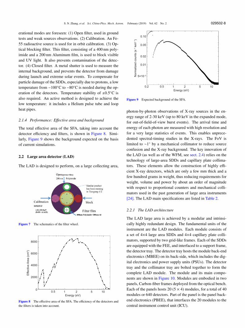
The total effective area of the SFA, taking into account thedetector efficiency and filters, is shown in Figure 8. Simi-larly, Figure 9 shows the background expected on the basisof current simulations.
2.2 Large area detector (LAD)
The LAD is designed to perform, on a large collecting area,
Figure 7 The schematics of the filter wheel.
2000
4000
6000
8000
0
Effective A
rea (
cm
2)
1 102
Energy (eV)
50.5
Figure 8 The effective area of the SFA. The efficiency of the detectors andthe filters is taken into account.
0.01
0.02
0.05
0.10
No
rma
lize
d c
oun
ts (
s−1 k
eV−1)
1 102
Energy (eV)
50.50.2
5×10⁻³
Figure 9 Expected background of the SFA.
photon-by-photon observations of X-ray sources in the en-ergy range of 2-30 keV (up to 80 keV in the expanded mode,for out-of-field-of-view burst events). The arrival time andenergy of each photon are measured with high resolution andfor a very large statistics of events. This enables unprece-dented spectral-timing studies in the X-rays. The FoV islimited to ∼1◦ by a mechanical collimator to reduce sourceconfusion and the X-ray background. The key innovation ofthe LAD (as well as of the WFM, see sect. 2.4) relies on thetechnology of large-area SDDs and capillary plate collima-tors. These elements allow the construction of highly effi-cient X-ray detectors, which are only a few mm thick and afew hundred grams in weight, thus reducing requirements forweight, volume and power by about an order of magnitudewith respect to proportional counters and mechanical colli-mators used in the past generation of large area instruments[24]. The LAD main specifications are listed in Table 2.
2.2.1 The LAD architecture
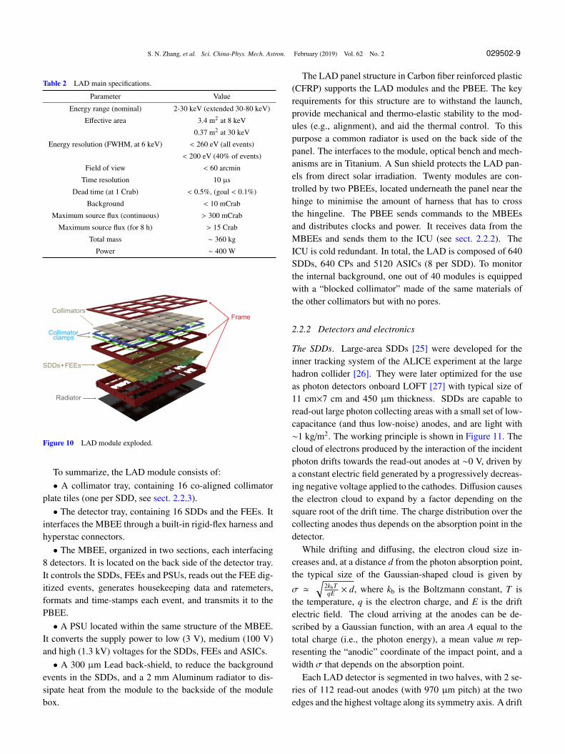
The LAD large area is achieved by a modular and intrinsi-cally highly redundant design. The fundamental units of theinstrument are the LAD modules. Each module consists ofa set of 4×4 large area SDDs and 4×4 capillary plate colli-mators, supported by two grid-like frames. Each of the SDDsare equipped with the FEE, and interfaced to a support frame,the detector tray. The detector tray hosts the module back-endelectronics (MBEE) on its back-side, which includes the dig-ital electronics and power supply units (PSUs). The detectortray and the collimator tray are bolted together to form thecomplete LAD module. The module and its main compo-nents are shown in Figure 10. Modules are embodied in twopanels, Carbon-fiber frames deployed from the optical bench.Each of the panels hosts 20 (5 × 4) modules, for a total of 40modules or 640 detectors. Part of the panel is the panel back-end electronics (PBEE), that interfaces the 20 modules to thecentral instrument control unit (ICU).
S. N. Zhang, et al. Sci. China-Phys. Mech. Astron. February (2019) Vol. 62 No. 2 029502-9
Table 2 LAD main specifications.
Parameter Value
Energy range (nominal) 2-30 keV (extended 30-80 keV)
Effective area 3.4 m2 at 8 keV
0.37 m2 at 30 keV
Energy resolution (FWHM, at 6 keV) < 260 eV (all events)
< 200 eV (40% of events)
Field of view < 60 arcmin
Time resolution 10 µs
Dead time (at 1 Crab) < 0.5%, (goal < 0.1%)
Background < 10 mCrab
Maximum source flux (continuous) > 300 mCrab
Maximum source flux (for 8 h) > 15 Crab
Total mass ∼ 360 kg
Power ∼ 400 W
Frame
Collimators
Collimatorclamps
SDDs+ FEEs
Radiator
Figure 10 LAD module exploded.
To summarize, the LAD module consists of:• A collimator tray, containing 16 co-aligned collimator
plate tiles (one per SDD, see sect. 2.2.3).• The detector tray, containing 16 SDDs and the FEEs. It
interfaces the MBEE through a built-in rigid-flex harness andhyperstac connectors.• The MBEE, organized in two sections, each interfacing
8 detectors. It is located on the back side of the detector tray.It controls the SDDs, FEEs and PSUs, reads out the FEE dig-itized events, generates housekeeping data and ratemeters,formats and time-stamps each event, and transmits it to thePBEE.• A PSU located within the same structure of the MBEE.
It converts the supply power to low (3 V), medium (100 V)and high (1.3 kV) voltages for the SDDs, FEEs and ASICs.• A 300 µm Lead back-shield, to reduce the background
events in the SDDs, and a 2 mm Aluminum radiator to dis-sipate heat from the module to the backside of the modulebox.
The LAD panel structure in Carbon fiber reinforced plastic(CFRP) supports the LAD modules and the PBEE. The keyrequirements for this structure are to withstand the launch,provide mechanical and thermo-elastic stability to the mod-ules (e.g., alignment), and aid the thermal control. To thispurpose a common radiator is used on the back side of thepanel. The interfaces to the module, optical bench and mech-anisms are in Titanium. A Sun shield protects the LAD pan-els from direct solar irradiation. Twenty modules are con-trolled by two PBEEs, located underneath the panel near thehinge to minimise the amount of harness that has to crossthe hingeline. The PBEE sends commands to the MBEEsand distributes clocks and power. It receives data from theMBEEs and sends them to the ICU (see sect. 2.2.2). TheICU is cold redundant. In total, the LAD is composed of 640SDDs, 640 CPs and 5120 ASICs (8 per SDD). To monitorthe internal background, one out of 40 modules is equippedwith a “blocked collimator” made of the same materials ofthe other collimators but with no pores.
2.2.2 Detectors and electronics
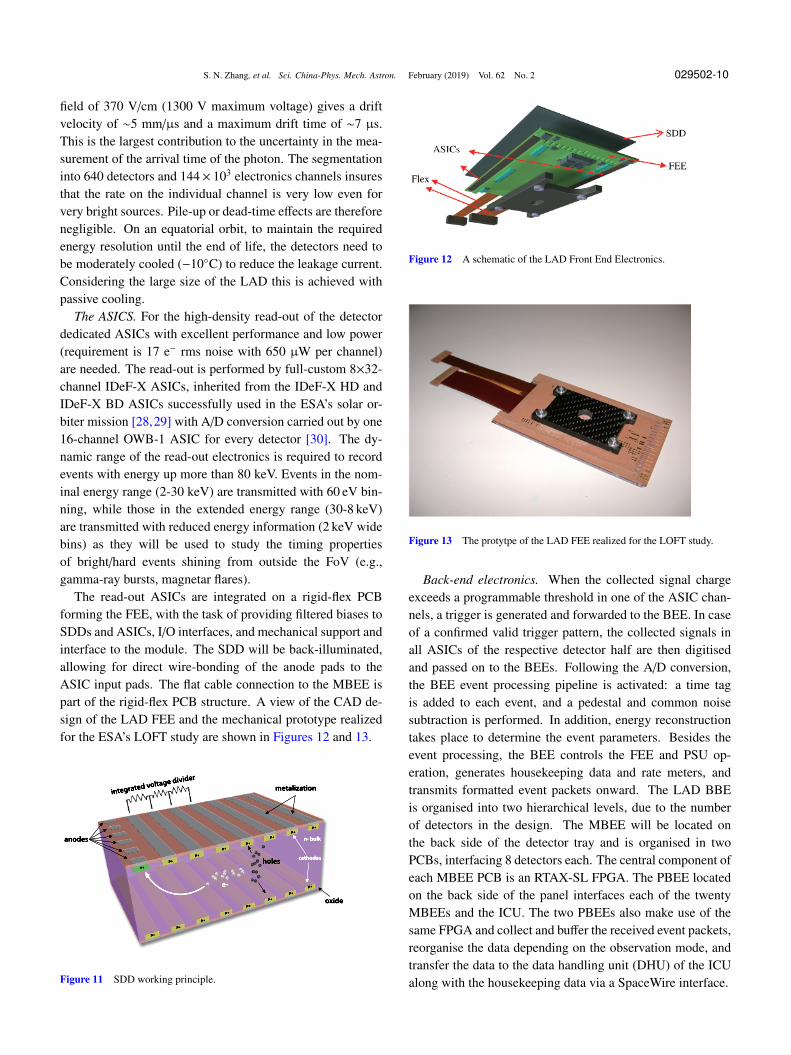
The SDDs. Large-area SDDs [25] were developed for theinner tracking system of the ALICE experiment at the largehadron collider [26]. They were later optimized for the useas photon detectors onboard LOFT [27] with typical size of11 cm×7 cm and 450 µm thickness. SDDs are capable toread-out large photon collecting areas with a small set of low-capacitance (and thus low-noise) anodes, and are light with∼1 kg/m2. The working principle is shown in Figure 11. Thecloud of electrons produced by the interaction of the incidentphoton drifts towards the read-out anodes at ∼0 V, driven bya constant electric field generated by a progressively decreas-ing negative voltage applied to the cathodes. Diffusion causesthe electron cloud to expand by a factor depending on thesquare root of the drift time. The charge distribution over thecollecting anodes thus depends on the absorption point in thedetector.
While drifting and diffusing, the electron cloud size in-creases and, at a distance d from the photon absorption point,the typical size of the Gaussian-shaped cloud is given by
σ ≃√
2kbTqE × d, where kb is the Boltzmann constant, T is
the temperature, q is the electron charge, and E is the driftelectric field. The cloud arriving at the anodes can be de-scribed by a Gaussian function, with an area A equal to thetotal charge (i.e., the photon energy), a mean value m rep-resenting the “anodic” coordinate of the impact point, and awidth σ that depends on the absorption point.
Each LAD detector is segmented in two halves, with 2 se-ries of 112 read-out anodes (with 970 µm pitch) at the twoedges and the highest voltage along its symmetry axis. A drift
S. N. Zhang, et al. Sci. China-Phys. Mech. Astron. February (2019) Vol. 62 No. 2 029502-10
field of 370 V/cm (1300 V maximum voltage) gives a driftvelocity of ∼5 mm/µs and a maximum drift time of ∼7 µs.This is the largest contribution to the uncertainty in the mea-surement of the arrival time of the photon. The segmentationinto 640 detectors and 144× 103 electronics channels insuresthat the rate on the individual channel is very low even forvery bright sources. Pile-up or dead-time effects are thereforenegligible. On an equatorial orbit, to maintain the requiredenergy resolution until the end of life, the detectors need tobe moderately cooled (−10◦C) to reduce the leakage current.Considering the large size of the LAD this is achieved withpassive cooling.
The ASICS. For the high-density read-out of the detectordedicated ASICs with excellent performance and low power(requirement is 17 e− rms noise with 650 µW per channel)are needed. The read-out is performed by full-custom 8×32-channel IDeF-X ASICs, inherited from the IDeF-X HD andIDeF-X BD ASICs successfully used in the ESA’s solar or-biter mission [28,29] with A/D conversion carried out by one16-channel OWB-1 ASIC for every detector [30]. The dy-namic range of the read-out electronics is required to recordevents with energy up more than 80 keV. Events in the nom-inal energy range (2-30 keV) are transmitted with 60 eV bin-ning, while those in the extended energy range (30-8 keV)are transmitted with reduced energy information (2 keV widebins) as they will be used to study the timing propertiesof bright/hard events shining from outside the FoV (e.g.,gamma-ray bursts, magnetar flares).
The read-out ASICs are integrated on a rigid-flex PCBforming the FEE, with the task of providing filtered biases toSDDs and ASICs, I/O interfaces, and mechanical support andinterface to the module. The SDD will be back-illuminated,allowing for direct wire-bonding of the anode pads to theASIC input pads. The flat cable connection to the MBEE ispart of the rigid-flex PCB structure. A view of the CAD de-sign of the LAD FEE and the mechanical prototype realizedfor the ESA’s LOFT study are shown in Figures 12 and 13.
Figure 11 SDD working principle.
Figure 12 A schematic of the LAD Front End Electronics.
Figure 13 The protytpe of the LAD FEE realized for the LOFT study.
Back-end electronics. When the collected signal chargeexceeds a programmable threshold in one of the ASIC chan-nels, a trigger is generated and forwarded to the BEE. In caseof a confirmed valid trigger pattern, the collected signals inall ASICs of the respective detector half are then digitisedand passed on to the BEEs. Following the A/D conversion,the BEE event processing pipeline is activated: a time tagis added to each event, and a pedestal and common noisesubtraction is performed. In addition, energy reconstructiontakes place to determine the event parameters. Besides theevent processing, the BEE controls the FEE and PSU op-eration, generates housekeeping data and rate meters, andtransmits formatted event packets onward. The LAD BBEis organised into two hierarchical levels, due to the numberof detectors in the design. The MBEE will be located onthe back side of the detector tray and is organised in twoPCBs, interfacing 8 detectors each. The central component ofeach MBEE PCB is an RTAX-SL FPGA. The PBEE locatedon the back side of the panel interfaces each of the twentyMBEEs and the ICU. The two PBEEs also make use of thesame FPGA and collect and buffer the received event packets,reorganise the data depending on the observation mode, andtransfer the data to the data handling unit (DHU) of the ICUalong with the housekeeping data via a SpaceWire interface.
S. N. Zhang, et al. Sci. China-Phys. Mech. Astron. February (2019) Vol. 62 No. 2 029502-11
Instrument control unit. The ICU forms the central con-trolling element of the instrument. It provides the interfaceto the spacecraft OBDH and also access to all instrumentsub-systems via SpaceWire. The ICU box consists of threecomponents: the DHU, the mass memory, the power dis-tribution unit (PDU). Standard tasks performed at the ICUlevel involve telecommand execution and distribution, accessto mass memory, time distribution and synchronisation, dataprocessing and compression, housekeeping data collection,instrument health monitoring and calibration tasks. The ICUbox contains each PCB board twice for cold redundancy.
2.2.3 Collimators, filters
To get full advantage of the compact detector design, a sim-ilarly compact collimator design is provided by the mechan-ical structure of the mature technology of the micro-channelplates, the capillary plates. In the LAD geometry, it is a 5 mmthick sheet of lead-glass (>40% Pb mass fraction) with thesame dimensions of the SDD detector, perforated by thou-sands of round micro-pores with a 83 µm diameter, limitingthe FoV to 0.95◦ (FWHM). The open area ratio of the de-vice is ≥75% (Figure 14). The thermal and optical design isthen completed by an additional optical filter, composed by athin (1 µm thickness) Kapton foil coated on both sides with40 nm of Aluminum. This is to guarantee a 10−6 filtering onIR/Visible/UV light, while transmitting >90% of the light at2 keV and above.
2.2.4 Performance: Area and background
eXTP will be launched into an almost equatorial low-earthorbit at an altitude of ∼550 km. At these latitudes, the ge-omagnetic field effectively screens primary cosmic rays upto energies of a few GeVs. Moreover, the satellite crossesthe South Atlantic Anomaly only in its external regions, thusminimizing the activation of materials. The main sources ofbackground considered in the simulation studies [31] are: (1)cosmic diffuse X-ray background [32]; (2) earth albedo γ-rays. We assumed the albedo spectrum as measured by BAT[33]; (3) residual primary cosmic rays, estimated from AMS
Figure 14 A prototype of the LAD Collimator developed by NNVT.
measurements [34, 35]; (4) secondary cosmic rays, estimatedfrom AMS measurements [34, 35], and analytically modeledby Mizuno et al. [36]; (5) earth albedo neutrons, modelledwith the QinetiQ Atmospheric Radiation Model (QARM)[37]; (6) natural radioactivity. Since the lead-glass collima-tors contain Potassium, radioactivity of 40K has to be con-sidered. This component will be largely reduced by adopt-ing the capillary plate technology of NNVT, which is almostpotassium-free.
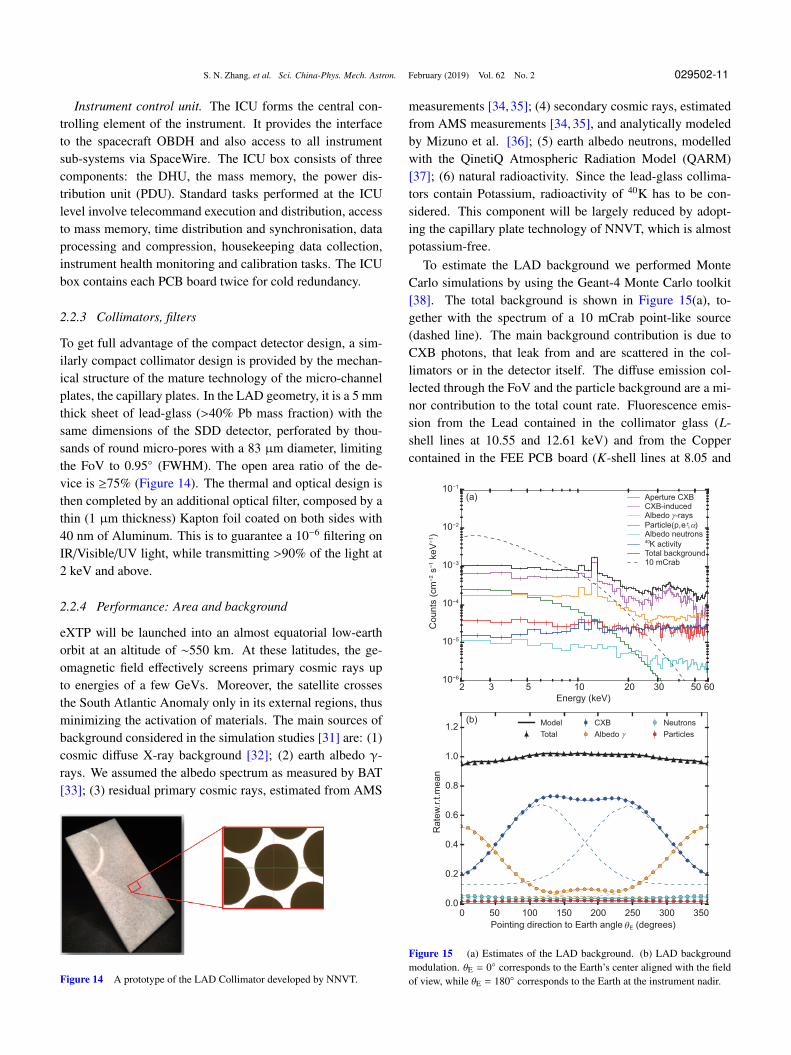
To estimate the LAD background we performed MonteCarlo simulations by using the Geant-4 Monte Carlo toolkit[38]. The total background is shown in Figure 15(a), to-gether with the spectrum of a 10 mCrab point-like source(dashed line). The main background contribution is due toCXB photons, that leak from and are scattered in the col-limators or in the detector itself. The diffuse emission col-lected through the FoV and the particle background are a mi-nor contribution to the total count rate. Fluorescence emis-sion from the Lead contained in the collimator glass (L-shell lines at 10.55 and 12.61 keV) and from the Coppercontained in the FEE PCB board (K-shell lines at 8.05 and
2 3 5 10 20 30 50 60
Energy (keV)
10−6
10−5
10−4
10−3
10−2
10−1
Cou
nts
(cm
−2 s
−1 k
eV
−1)
Aperture CXB
CXB-induced
Albedo γ-rays
Particle(p,e±,α)
Albedo neutrons40
K activity
Total background
10 mCrab
0 50 100 150 200 250 300 350
Pointing direction to Earth angle
0.0
0.2
0.4
0.6
0.8
1.0
1.2
Rate
w.r.t.m
ean
Model
Total
CXB
Albedo γ
Neutrons
Particles
E (degrees)θ
(a)
(b)
Figure 15 (a) Estimates of the LAD background. (b) LAD backgroundmodulation. θE = 0◦ corresponds to the Earth’s center aligned with the fieldof view, while θE = 180◦ corresponds to the Earth at the instrument nadir.
S. N. Zhang, et al. Sci. China-Phys. Mech. Astron. February (2019) Vol. 62 No. 2 029502-12
8.90 keV) is present. The Figure 15(b) shows an evaluation ofthe background as a function of the angle between the LADpointing direction and the center of the Earth. The maximumexpected modulation of the background is ∼10%. Since it isdue to geometry, it can be predicted and modeled. By using aset of “blocked” detectors to monitor the instantaneous back-ground, the overall background can be constrained to betterthan 0.5%.
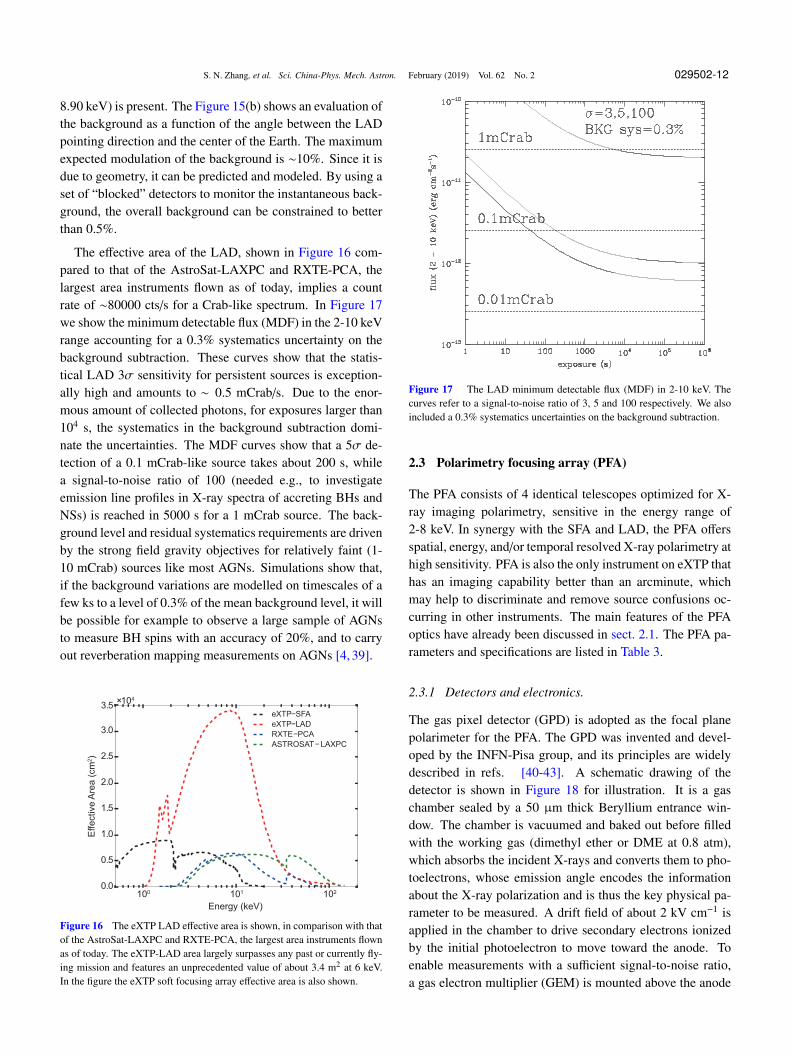
The effective area of the LAD, shown in Figure 16 com-pared to that of the AstroSat-LAXPC and RXTE-PCA, thelargest area instruments flown as of today, implies a countrate of ∼80000 cts/s for a Crab-like spectrum. In Figure 17we show the minimum detectable flux (MDF) in the 2-10 keVrange accounting for a 0.3% systematics uncertainty on thebackground subtraction. These curves show that the statis-tical LAD 3σ sensitivity for persistent sources is exception-ally high and amounts to ∼ 0.5 mCrab/s. Due to the enor-mous amount of collected photons, for exposures larger than104 s, the systematics in the background subtraction domi-nate the uncertainties. The MDF curves show that a 5σ de-tection of a 0.1 mCrab-like source takes about 200 s, whilea signal-to-noise ratio of 100 (needed e.g., to investigateemission line profiles in X-ray spectra of accreting BHs andNSs) is reached in 5000 s for a 1 mCrab source. The back-ground level and residual systematics requirements are drivenby the strong field gravity objectives for relatively faint (1-10 mCrab) sources like most AGNs. Simulations show that,if the background variations are modelled on timescales of afew ks to a level of 0.3% of the mean background level, it willbe possible for example to observe a large sample of AGNsto measure BH spins with an accuracy of 20%, and to carryout reverberation mapping measurements on AGNs [4, 39].
100 101 102
Energy (keV)
0.0
0.5
1.0
1.5
2.0
2.5
3.0
3.5
Effective A
rea (
cm
2)
×104
eXTP−SFA
eXTP−LAD
RXTE−PCA
ASTROSAT−LAXPC
Figure 16 The eXTP LAD effective area is shown, in comparison with thatof the AstroSat-LAXPC and RXTE-PCA, the largest area instruments flownas of today. The eXTP-LAD area largely surpasses any past or currently fly-ing mission and features an unprecedented value of about 3.4 m2 at 6 keV.In the figure the eXTP soft focusing array effective area is also shown.
Figure 17 The LAD minimum detectable flux (MDF) in 2-10 keV. Thecurves refer to a signal-to-noise ratio of 3, 5 and 100 respectively. We alsoincluded a 0.3% systematics uncertainties on the background subtraction.
2.3 Polarimetry focusing array (PFA)
The PFA consists of 4 identical telescopes optimized for X-ray imaging polarimetry, sensitive in the energy range of2-8 keV. In synergy with the SFA and LAD, the PFA offersspatial, energy, and/or temporal resolved X-ray polarimetry athigh sensitivity. PFA is also the only instrument on eXTP thathas an imaging capability better than an arcminute, whichmay help to discriminate and remove source confusions oc-curring in other instruments. The main features of the PFAoptics have already been discussed in sect. 2.1. The PFA pa-rameters and specifications are listed in Table 3.
2.3.1 Detectors and electronics.
The gas pixel detector (GPD) is adopted as the focal planepolarimeter for the PFA. The GPD was invented and devel-oped by the INFN-Pisa group, and its principles are widelydescribed in refs. [40-43]. A schematic drawing of thedetector is shown in Figure 18 for illustration. It is a gaschamber sealed by a 50 µm thick Beryllium entrance win-dow. The chamber is vacuumed and baked out before filledwith the working gas (dimethyl ether or DME at 0.8 atm),which absorbs the incident X-rays and converts them to pho-toelectrons, whose emission angle encodes the informationabout the X-ray polarization and is thus the key physical pa-rameter to be measured. A drift field of about 2 kV cm−1 isapplied in the chamber to drive secondary electrons ionizedby the initial photoelectron to move toward the anode. Toenable measurements with a sufficient signal-to-noise ratio,a gas electron multiplier (GEM) is mounted above the anode
S. N. Zhang, et al. Sci. China-Phys. Mech. Astron. February (2019) Vol. 62 No. 2 029502-13
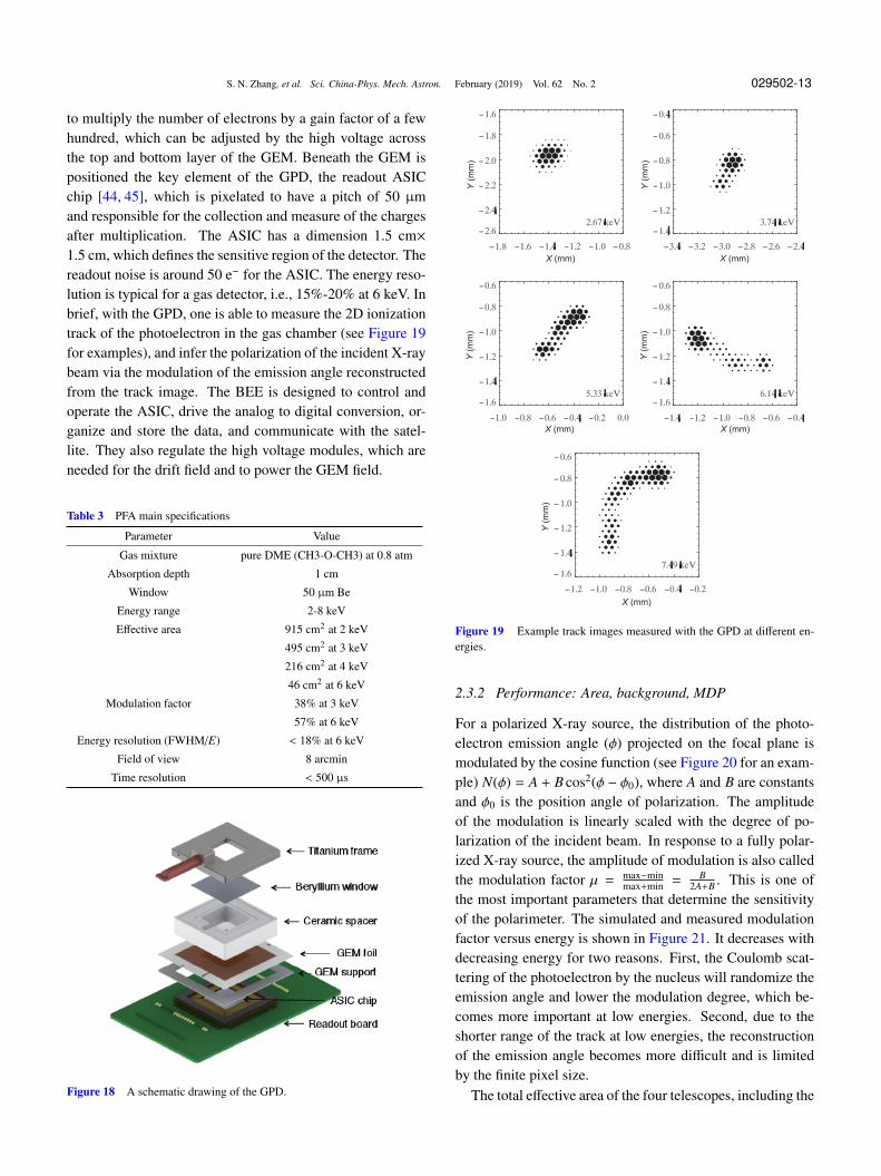
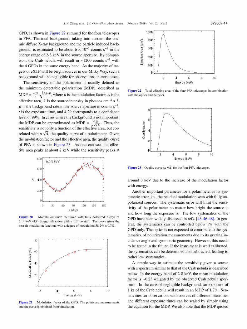
to multiply the number of electrons by a gain factor of a fewhundred, which can be adjusted by the high voltage acrossthe top and bottom layer of the GEM. Beneath the GEM ispositioned the key element of the GPD, the readout ASICchip [44, 45], which is pixelated to have a pitch of 50 µmand responsible for the collection and measure of the chargesafter multiplication. The ASIC has a dimension 1.5 cm×1.5 cm, which defines the sensitive region of the detector. Thereadout noise is around 50 e− for the ASIC. The energy reso-lution is typical for a gas detector, i.e., 15%-20% at 6 keV. Inbrief, with the GPD, one is able to measure the 2D ionizationtrack of the photoelectron in the gas chamber (see Figure 19for examples), and infer the polarization of the incident X-raybeam via the modulation of the emission angle reconstructedfrom the track image. The BEE is designed to control andoperate the ASIC, drive the analog to digital conversion, or-ganize and store the data, and communicate with the satel-lite. They also regulate the high voltage modules, which areneeded for the drift field and to power the GEM field.
Table 3 PFA main specifications
Parameter Value
Gas mixture pure DME (CH3-O-CH3) at 0.8 atm
Absorption depth 1 cm
Window 50 µm Be
Energy range 2-8 keV
Effective area 915 cm2 at 2 keV
495 cm2 at 3 keV
216 cm2 at 4 keV
46 cm2 at 6 keV
Modulation factor 38% at 3 keV
57% at 6 keV
Energy resolution (FWHM/E) < 18% at 6 keV
Field of view 8 arcmin
Time resolution < 500 µs
Figure 18 A schematic drawing of the GPD.
Y (
mm
)
X (mm)
Y (
mm
)
X (mm)
Y (
mm
)
X (mm)
Y (
mm
)
X (mm)
Y (
mm
)
X (mm)
Figure 19 Example track images measured with the GPD at different en-ergies.
2.3.2 Performance: Area, background, MDP
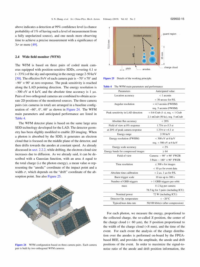
For a polarized X-ray source, the distribution of the photo-electron emission angle (ϕ) projected on the focal plane ismodulated by the cosine function (see Figure 20 for an exam-ple) N(ϕ) = A + B cos2(ϕ − ϕ0), where A and B are constantsand ϕ0 is the position angle of polarization. The amplitudeof the modulation is linearly scaled with the degree of po-larization of the incident beam. In response to a fully polar-ized X-ray source, the amplitude of modulation is also calledthe modulation factor µ = max−min
max+min =B
2A+B . This is one ofthe most important parameters that determine the sensitivityof the polarimeter. The simulated and measured modulationfactor versus energy is shown in Figure 21. It decreases withdecreasing energy for two reasons. First, the Coulomb scat-tering of the photoelectron by the nucleus will randomize theemission angle and lower the modulation degree, which be-comes more important at low energies. Second, due to theshorter range of the track at low energies, the reconstructionof the emission angle becomes more difficult and is limitedby the finite pixel size.
The total effective area of the four telescopes, including the
S. N. Zhang, et al. Sci. China-Phys. Mech. Astron. February (2019) Vol. 62 No. 2 029502-14
GPD, is shown in Figure 22 summed for the four telescopesin PFA. The total background, taking into account the cos-mic diffuse X-ray background and the particle induced back-ground, is estimated to be about 6 × 10⁻³ counts s−1 in theenergy range of 2-8 keV in the source aperture. By compar-ison, the Crab nebula will result in ∼1200 counts s−1 withthe 4 GPDs in the same energy band. As the majority of tar-gets of eXTP will be bright sources in our Milky Way, such abackground will be negligible for observations in most cases.
The sensitivity of the polarimeter is usually defined asthe minimum detectable polarization (MDP), described as
MDP = 4.29µ
√S A+B
t , where µ is the modulation factor, A is the
effective area, S is the source intensity in photons cm−2 s−1,B is the background rate in the source aperture in counts s−1,t is the exposure time, and 4.29 corresponds to a confidencelevel of 99%. In cases where the background is not important,the MDP can be approximated as MDP = 4.29
µ√
S At. Thus, the
sensitivity is not only a function of the effective area, but cor-related with µ
√A, the quality curve of a polarimeter. Given
the modulation factor and the effective area, the quality curveof PFA is shown in Figure 23. As one can see, the effec-tive area peaks at about 2 keV while the sensitivity peaks at
Figure 20 Modulation curve measured with fully polarized X-rays of6.14 keV (45◦ Bragg diffraction with a LiF crystal). The curve gives thebest-fit modulation function, with a degree of modulation 58.2% ± 0.7%.
Figure 21 Modulation factor of the GPD. The points are measurementsand the curve is obtained from simulation.
Figure 22 Total effective area of the four PFA telescopes in combinationwith the optics and detector.
Figure 23 Quality curve (µ√
A) for the four PFA telescopes.
around 3 keV due to the increase of the modulation factorwith energy.
Another important parameter for a polarimeter is its sys-tematic error, i.e., the residual modulation seen with fully un-polarized sources. The systematic error will limit the sensi-tivity of the polarimeter no matter how bright the source isand how long the exposure is. The low systematics of theGPD have been widely discussed in refs. [43,46-48]. In gen-eral, the systematics can be controlled below 1% with theGPD only. The optics is not expected to contribute to the sys-tematics of polarization measurements due to its grazing in-cidence angle and symmetric geometry. However, this needsto be tested in the future. If the instrument is well calibrated,the systematics can be determined and subtracted, leading torather low systematics.
A simple way to estimate the sensitivity given a sourcewith a spectrum similar to that of the Crab nebula is describedbelow. In the energy band of 2-8 keV, the mean modulationfactor is ∼0.23 weighted by the observed Crab nebula spec-trum. In the case of negligible background, an exposure of1 ks of the Crab nebula will result in an MDP of 1.7%. Sen-sitivities for observations with sources of different intensitiesand different exposure times can be scaled by simply usingthe equation for the MDP. We also note that the MDP quoted
S. N. Zhang, et al. Sci. China-Phys. Mech. Astron. February (2019) Vol. 62 No. 2 029502-15
above indicates a detection at 99% confidence level (a chanceprobability of 1% of having such a level of measurement froma fully unpolarized source), and one needs more observingtime to achieve a precise measurement with a significance of3σ or more [49].
2.4 Wide field monitor (WFM)
The WFM is based on three pairs of coded mask cam-eras equipped with position-sensitive SDDs, covering 4.1 sr(∼33%) of the sky and operating in the energy range 2-50 keV[50]. The effective FoV of each camera pair is ∼70◦×70◦ and∼90◦ × 90◦ at zero response. The peak sensitivity is reachedalong the LAD pointing direction. The energy resolution is∼300 eV at 6 keV, and the absolute time accuracy is 1 µs.Pairs of two orthogonal cameras are combined to obtain accu-rate 2D positions of the monitored sources. The three camerapairs (six cameras in total) are arranged in a baseline config-uration of −60◦, 0◦, 60◦ as shown in Figure 24. The WFMmain parameters and anticipated performance are listed inTable 4.
The WFM detector plane is based on the same large areaSDD technology developed for the LAD. The detector geom-etry has been sligthly modified to enable 2D imaging. Whena photon is absorbed by the SDD, it generates an electroncloud that is focused on the middle plane of the detector, andthen drifts towards the anodes at constant speed. As alreadydiscussed in sect. 2.2.2, while drifting, the electron cloud sizeincreases due to diffusion. As we already said, it can be de-scribed with a Gaussian function, with an area A equal tothe total charge (i.e the photon energy), a mean value m rep-resenting the “anodic” coordinate of the impact point and awidth σ, which depends on the “drift” coordinate of the ab-sorption point. See also Figure 25.
Figure 24 WFM configuration based on three camera pairs. Each camerapair is built by two orthogonal WFM cameras.
guard region Incident photons
charge cloud anodes pitch
72
,5 m
m
35
mm
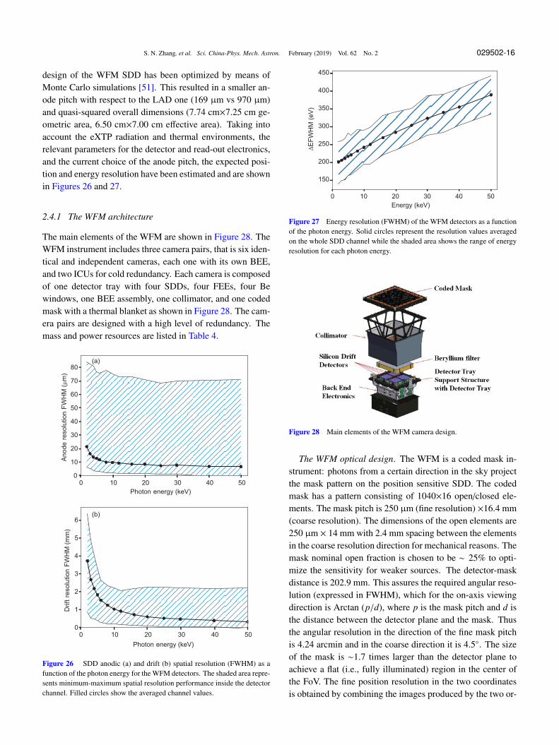
Figure 25 Details of the working principle.
Table 4 The WFM main parameters and performance
Parameters Anticipated value
Location accuracy < 1 arcmin
< 30 arcsec for P/L
Angular resolution < 4.3 arcmin (FWHM)
req. 5 arcmin (FWHM)
Peak sensitivity in LAD direction < 0.6 Crab (1 s), req. < 1 Crab
2.1 mCrab (50 ks), req. 5 mCrab
Absolute flux accuracy < 20%
Field of view at 0% response 1.75π sr=5.5 sr
at 20% of peak camera response 1.33π sr =4.1 sr
Energy range 2-50 keV
Energy resolution (FWHM) < 300 eV at 6 keV
req. < 500 eV at 6 keV
Energy scale accuracy < 2%
Energy bands for compressed images ≥ 64
Field of view Camera: ∼ 90◦ × 90◦ FWZR
3 Pairs ∼ 180◦ × 90◦ FWZR
Time resolution ≤ 300 s for images
< 10 µs for event data
Absolute time calibration < 2 µs, 1 µs for P/L
Burst trigger scale 10 ms up to 300 s
Number of GRB triggers > 1 GRB triggers per orbit
mass 11.2 kg per camera
78.5 kg for 3 pairs (including ICU)
Nominal power 72 W (including ICU)
Detector Op. temperature < −20◦C
Typical/max data rate 50/100 kbits/s (after compression)
For each photon, we measure the energy, proportional tothe collected charge, the so-called X-position, the center ofthe charge cloud (< 60 µm), the Y-position proportional tothe width of the charge cloud (<8 mm), and the time of theevent. For each event the analysis of the charge distribu-tion over the anodes is performed on-board by the FPGA-based BEE, and provides the amplitude, the anode and driftpositions of the event. In order to maximize the signal-to-noise ratio of the anode and drift position information, the
S. N. Zhang, et al. Sci. China-Phys. Mech. Astron. February (2019) Vol. 62 No. 2 029502-16
design of the WFM SDD has been optimized by means ofMonte Carlo simulations [51]. This resulted in a smaller an-ode pitch with respect to the LAD one (169 µm vs 970 µm)and quasi-squared overall dimensions (7.74 cm×7.25 cm ge-ometric area, 6.50 cm×7.00 cm effective area). Taking intoaccount the eXTP radiation and thermal environments, therelevant parameters for the detector and read-out electronics,and the current choice of the anode pitch, the expected posi-tion and energy resolution have been estimated and are shownin Figures 26 and 27.
2.4.1 The WFM architecture
The main elements of the WFM are shown in Figure 28. TheWFM instrument includes three camera pairs, that is six iden-tical and independent cameras, each one with its own BEE,and two ICUs for cold redundancy. Each camera is composedof one detector tray with four SDDs, four FEEs, four Bewindows, one BEE assembly, one collimator, and one codedmask with a thermal blanket as shown in Figure 28. The cam-era pairs are designed with a high level of redundancy. Themass and power resources are listed in Table 4.
0 10 20 30 40 50
Photon energy (keV)
0
10
20
30
40
50
60
70
80
Ano
de
reso
lution
FW
HM
(µ
m)
0 10 20 30 40 50
Photon energy (keV)
0
1
2
3
4
5
6
Drift
resolu
tion
FW
HM
(m
m)
(a)
(b)
Figure 26 SDD anodic (a) and drift (b) spatial resolution (FWHM) as afunction of the photon energy for the WFM detectors. The shaded area repre-sents minimum-maximum spatial resolution performance inside the detectorchannel. Filled circles show the averaged channel values.
0 10 20 30 40 50
Energy (keV)
150
200
250
300
350
400
450
∆E
FW
HM
(e
V)
Figure 27 Energy resolution (FWHM) of the WFM detectors as a functionof the photon energy. Solid circles represent the resolution values averagedon the whole SDD channel while the shaded area shows the range of energyresolution for each photon energy.
Figure 28 Main elements of the WFM camera design.
The WFM optical design. The WFM is a coded mask in-strument: photons from a certain direction in the sky projectthe mask pattern on the position sensitive SDD. The codedmask has a pattern consisting of 1040×16 open/closed ele-ments. The mask pitch is 250 µm (fine resolution) ×16.4 mm(coarse resolution). The dimensions of the open elements are250 µm × 14 mm with 2.4 mm spacing between the elementsin the coarse resolution direction for mechanical reasons. Themask nominal open fraction is chosen to be ∼ 25% to opti-mize the sensitivity for weaker sources. The detector-maskdistance is 202.9 mm. This assures the required angular reso-lution (expressed in FWHM), which for the on-axis viewingdirection is Arctan (p/d), where p is the mask pitch and d isthe distance between the detector plane and the mask. Thusthe angular resolution in the direction of the fine mask pitchis 4.24 arcmin and in the coarse direction it is 4.5◦. The sizeof the mask is ∼1.7 times larger than the detector plane toachieve a flat (i.e., fully illuminated) region in the center ofthe FoV. The fine position resolution in the two coordinatesis obtained by combining the images produced by the two or-
S. N. Zhang, et al. Sci. China-Phys. Mech. Astron. February (2019) Vol. 62 No. 2 029502-17
thogonal and co-aligned cameras forming each WFM camerapair.
Coded mask, mask frame. The coded mask area is 260 mm× 260 mm and is manufactured from a 150 µm thick Tung-sten foil. There are strict requirements on the flatness andstability of the coded mask. The mask must be flat (or at leastmust maintain its shape) to ±50 µm over its entire surfaceacross the full operational temperature range. Temperaturegradients during the orbit must be less than 10◦C. This is themain reason why a sunshield is a requirement for the WFM.The mask frame acts as a pretension mechanism in order tominimize the vertical displacements of the mask during theoperational mode.
Collimator. The collimator supports the coded mask frameassembly and is made of CFRP material. It has been selectedbecause it is light and has enough stiffness to avoid defor-mations, which can appear during launch (accelerations) andoperation (thermal stresses). The collimator will be coveredby a Tungsten sheet as a background shield. In addition, Cop-per and Molybdenum plates will be placed in the inner partof the collimator for in-flight calibration purposes.
Detector tray. The detector tray assembly consists offour detector assemblies (DAs) and the detector support plate(DSP). Each detector assembly consists of an SDD tile gluedon a ceramic PCB, containing the FEE. Three invar mount-ing legs provide the mechanical interface for alignment of theDA to the DSP. Likewise, DSP will be used to mechanicallyalign the four DAs with respect to each other.
Beryllium window and detector tray support structure. A25 µm thick Beryllium foil is located above each SDD asprotection against micrometeoroid impacts and debris. Thedetector tray support structure (DTSS) serves as a support forthe DSP, and facilitates the mounting of the collimator andBEE box support structure, which accommodates the BEEbox. In addition, the isostatic fitting is mounted on the DTSSand serves as mechanical interface between the camera andthe support structure.
Back-end electronics and ICU. There is only one level ofBEE, as there are only four detectors to be read out per cam-era. The BEE box is located along with the PSU at thebottom of each camera. Although most of the processingis similar to that of the LAD BEE, the WFM BEE has theadditional capability to determine rather accurate photon po-sitions for each photon from the FEE data. A higher levelof processing power is therefore required inside the BEEs.High-resolution detector images in several energy bands areaccumulated directly on board. For this purpose, the WFMBEE will be based on an RTG4 FPGA that is larger, faster andmore flexible than the RTAX-SL. As in the PBEE of the LAD,the WFM BEE will transfer the science data products to theWFM ICU along with the housekeeping data via a SpaceWire
interface. The WFM ICU consists of a main and a redundantunit, housed in two separate boxes. The ICU controls each ofthe six cameras independently and interfaces with the PDHU,performing on-board computations to locate bright transientevents in real time.
Thermal control. A stable thermal environment is obtainedby protecting the instrument with a sunshield. The operatingtemperature range of the four SDD/FEE sandwiches are be-tween −30◦C and −3◦C. Their internal heat dissipation willbe dissipated mainly via conduction to the thermal interfaceprovided by the S/C. The coded mask is covered by a thermalblanket in order to reduce mask temperature variations alongthe orbit and within the mask. The power dissipated by theBEE will be radiatively transferred to the optical bench anddeep sky via the backside of the BEE box. In addition, anMLI blanket will wrap the collimator, to provide an optimalisolation to the SDD/FEE sandwich, and to keep the cameraalignment within the desired margin during the mission.
2.4.2 Performance
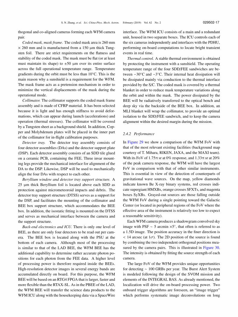
In Figure 29 we show a comparison of the WFM FoV withthat of the most relevant existing facilities (background mapcourtesy of T. Mihara, RIKEN, JAXA, and the MAXI team).With its FoV of 1.75π sr at 0% response, and 1.33π sr at 20%of the peak camera response, the WFM will have the largestFoV in comparison with that of other similar instruments.This is essential in view of the detection of counterparts ofgravitational wave sources. On the map, yellow diamondsindicate known Be X-ray binary systems, red crosses indi-cate supergiant HMXBs, orange crosses SFXTs, and magentaboxes SyXBs. Grayed-out sources are those falling outsidethe WFM FoV during a single pointing toward the GalacticCenter (or located in peripheral regions of the FoV where theeffective area of the instrument is relatively too low to expecta reasonable sensitivity).
Each WFM camera produces a shadowgram convolved skyimage with PSF ∼ 5 arcmin ×5◦, that often is referred to asa 1.5D image. The position accuracy in the finer direction is< 14 arcsec (at 1σ). The 2D position of the source is foundby combining the two independent orthogonal positions mea-sured by the camera pairs. This is illustrated in Figure 30.The intensity is obtained by fitting the source strength of eachcamera.
The large FoV of the WFM provides unique opportunitiesfor detecting ∼ 100 GRBs per year. The Burst Alert Systemis modeled following the design of the SVOM mission andelements of the INTEGRAL BAS. As already mentioned, thelocalization will drive the on-board processing power. Twoonboard trigger algorithms are foreseen, an “image trigger”which performs systematic image deconvolutions on long
S. N. Zhang, et al. Sci. China-Phys. Mech. Astron. February (2019) Vol. 62 No. 2 029502-18
time scales, and a “count rate trigger”, which as a first firststep selects short time scales of counts in excess over back-ground to be deconvolved in a second step. The detectionof an uncatalogued source gives rise to a well localized burstcandidate. The on-board VHF transmitter will transmit shortmessages with time and sky position to a network of smallground stations heritage of SVOM. The goal is to deliver trig-ger time and burst position to end users within 30 s for fastfollow-up of the fading GRB afterglow.
3 The mission profile
The main parameters of the mission are listed in Table 5 [52].
Figure 29 The WFM FoV, red curve, is compared with other relevantall sky monitoring instruments. On the map, yellow diamonds mark theknown Be X-ray binary systems, red crosses mark supergiant HMXBs, or-ange crosses the SFXTs, and magenta boxes the SyXBs. Grayed-out sourcesare those falling outside the WFM FoV during a single pointing toward theGalactic Center (Background map courtesy of T. Mihara, RIKEN, JAXA,and the MAXI team).
Figure 30 The two-dimensional position of a source is obtained by com-bining the images of the two pairs of each camera, which are orthogonallyoriented with respect to each other. The position accuracy in the fine direc-tion is < 14 arcsec (at 1σ).
Table 5 The main parameters of the mission
Parameter Value
Orbit altitude and inclination 550 km, < 2.5◦
Launcher and launch base LM7 + upper stage, Wenchang
Launch mass 4500 kg
Power ∼5 kW
Telemetry rate, band 3.2 Tb/day, X-band or Ka-band
Pointing 3-axis stabilized, < 0.01◦ (3σ)
Ground stations Sanya (China), Malindi (Kenya)
Burst alert VHF transmitter,BeiDou Navigation Satellite System
Mission lifetime 5 years (goal 8 years)
Launch date 2025
3.1 The spacecraft
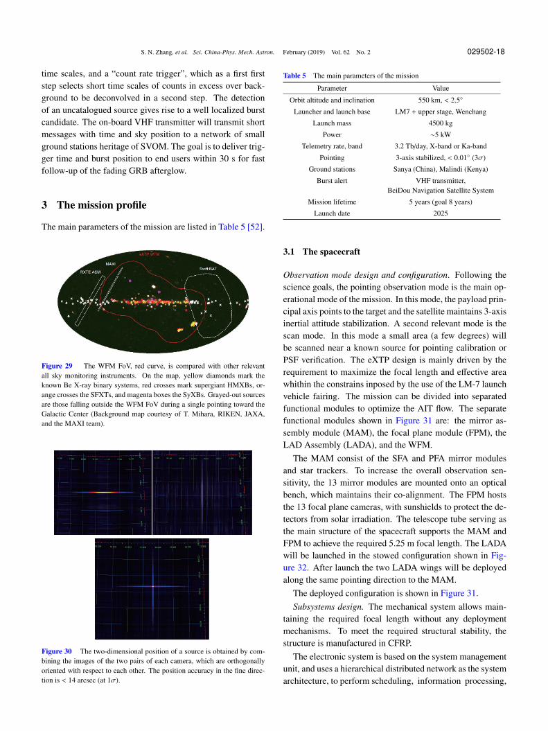
Observation mode design and configuration. Following thescience goals, the pointing observation mode is the main op-erational mode of the mission. In this mode, the payload prin-cipal axis points to the target and the satellite maintains 3-axisinertial attitude stabilization. A second relevant mode is thescan mode. In this mode a small area (a few degrees) willbe scanned near a known source for pointing calibration orPSF verification. The eXTP design is mainly driven by therequirement to maximize the focal length and effective areawhithin the constrains inposed by the use of the LM-7 launchvehicle fairing. The mission can be divided into separatedfunctional modules to optimize the AIT flow. The separatefunctional modules shown in Figure 31 are: the mirror as-sembly module (MAM), the focal plane module (FPM), theLAD Assembly (LADA), and the WFM.
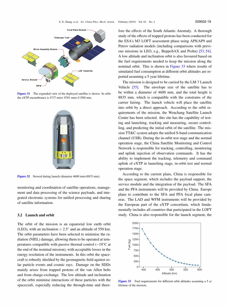
The MAM consist of the SFA and PFA mirror modulesand star trackers. To increase the overall observation sen-sitivity, the 13 mirror modules are mounted onto an opticalbench, which maintains their co-alignment. The FPM hoststhe 13 focal plane cameras, with sunshields to protect the de-tectors from solar irradiation. The telescope tube serving asthe main structure of the spacecraft supports the MAM andFPM to achieve the required 5.25 m focal length. The LADAwill be launched in the stowed configuration shown in Fig-ure 32. After launch the two LADA wings will be deployedalong the same pointing direction to the MAM.
The deployed configuration is shown in Figure 31.Subsystems design. The mechanical system allows main-
taining the required focal length without any deploymentmechanisms. To meet the required structural stability, thestructure is manufactured in CFRP.
The electronic system is based on the system managementunit, and uses a hierarchical distributed network as the systemarchitecture, to perform scheduling, information processing,
S. N. Zhang, et al. Sci. China-Phys. Mech. Astron. February (2019) Vol. 62 No. 2 029502-19
Figure 31 The expanded view of the deployed satellite is shown. In orbitthe eXTP encumbrance is 4737 mm× 8781 mm×11500 mm.
Figure 32 Stowed during launch (diameter 4600 mm×8835 mm).
monitoring and coordination of satellite operations, manage-ment and data processing of the science payloads, and inte-grated electronic systems for unified processing and sharingof satellite information.
3.2 Launch and orbit
The orbit of the mission is an equatorial low earth orbit(LEO), with an inclination < 2.5◦ and an altitude of 550 km.The orbit parameters have been selected to minimise the ra-diation (NIEL) damage, allowing them to be operated at tem-peratures compatible with passive thermal control (−10◦C atthe end of the nominal mission), with acceptable losses in theenergy resolution of the instruments. In this orbit the space-craft is robustly shielded by the geomagnetic field against so-lar particle events and cosmic rays. Damage on the SDDsmainly arises from trapped protons of the van Allen beltsand from charge-exchange. The low altitude and inclinationof the orbit minimise interactions of these particles with thespacecraft, especially reducing the through-time and there-
fore the effects of the South Atlantic Anomaly. A thoroughstudy of the effects of trapped protons has been conducted forthe ESA’s M3 LOFT assessment phase using AP8/AP9 andPetrov radiation models (including comparisons with previ-ous missions in LEO, e.g., BeppoSAX and Proba) [53, 54].A low altitude and inclination orbit is also favoured based onthe fuel requirements needed to keep the mission along thenominal orbit. This is shown in Figure 33 where results ofsimulated fuel consumption at different orbit altitudes are re-ported assuming a 5 year lifetime.
The mission is designed to be carried by the LM-7 LaunchVehicle [55]. The envelope size of the satellite has tobe within a diameter of 4600 mm, and the total height is8835 mm, which is compatible with the constrains of thecarrier fairing. The launch vehicle will place the satelliteinto orbit by a direct approach. According to the orbit re-quirements of the mission, the Wenchang Satellite LaunchCenter has been selected. this site has the capability of test-ing and launching, tracking and measuring, secure control-ling, and predicting the initial orbit of the satellite. The mis-sion TT&C system adopts the unified S-band communicationchannel (USB). During the in-orbit test stage and the normaloperation stage, the China Satellite Monitoring and ControlNetwork is responsible for tracking, controlling, monitoringand uplink injection of observation commands. It has theability to implement the tracking, telemetry and commanduplink of eXTP in launching stage, in-orbit test and normaloperation stage.
According to the current plans, China is responsible forthe space segment, which includes the payload support, theservice module and the integration of the payload. The SFAand the PFA instruments will be provided by China. Europeplans to contribute to the SFA and PFA focal plane cam-eras. The LAD and WFM instruments will be provided bythe European part of the eXTP consortium, which funda-mentally includes all countries that participated in the LOFTstudy. China is also responsible for the launch segment, the
400 450 500 550 600
Altitude (km)
0
250
500
750
1000
1250
1500
1750
2000
Fuel (k
g)
Figure 33 Fuel requirements for different orbit altitudes assuming a 5 yrlifetime of the mission.
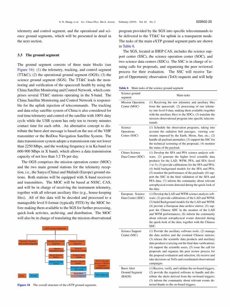
S. N. Zhang, et al. Sci. China-Phys. Mech. Astron. February (2019) Vol. 62 No. 2 029502-20
telemetry and control segment, and the operational and sci-ence ground segments, which will be presented in detail inthe next section.
3.3 The ground segment
The ground segment consists of three main blocks (seeFigure 34): (1) the telemetry, tracking, and control segment(TT&C); (2) the operational ground segment (OGS); (3) thescience ground segment (SGS). The TT&C leads the mon-itoring and verification of the spacecraft health by using theChina Satellite Monitoring and Control Network, which com-prises several TT&C stations operating in the S-band. TheChina Satellite Monitoring and Control Network is responsi-ble for the uplink injection of telecommands. The trackingand data relay satellite system of China is also considered forreal time telemetry and control of the satellite with 100% dutycycle while the USB system has only ten to twenty minutescontact time for each orbit. An alternative concept to dis-tribute the burst alert message is based on the use of the VHFtransmitter or the BeiDou Navigation Satellite System. Thedata transmission system adopts a transmission rate not lowerthan 2250 Mbps, and the working frequency is in Ka band (or600-900 Mbps in X band), which allows a data transmissioncapacity of not less than 3.2 Tb per day.
The OGS comprises the mission operation center (MOC)and the two main ground stations for the telemetry recep-tion, i.e., the Sanya (China) and Malindi (Europe) ground sta-tions. Both stations will be equipped with X-band receiversand transmitters. The MOC will be based at NSSC, CAS,and will be in charge of receiving the instrument telemetry,together with all relevant auxiliary files (e.g., house-keepingfiles). All of this data will be decoded and processed to amanageable level 0 format (typically FITS) by the MOC be-fore making them available to the SGS for further processing,quick-look activites, archiving, and distribution. The MOCwill also be in charge of translating the mission observational
eXTP Ground Segments
Telemetry Tracking,
and Control Segment
Operational Ground
Segment
Science Ground
Segment
Mission
Operations Center
Science
Operations Center
Sanya Ground
Station
Science Data
Center
Malindi Ground
Station
Science Support
Center
Short message
service of BeiDou
Navigation
satellite systemEuropean science
data center
Burst Alert
Ground SegmentVHF antennas
EuropeChina
Figure 34 The overall structure of the eXTP ground segments.
program provided by the SGS into specific telecommands tobe delivered to the TT&C for uplink in a transparent mode.The tasks of the main eXTP ground segment parts are shownin Table 6.
The SGS, located at IHEP CAS, includes the science sup-port center (SSC), the science operation center (SOC), andtwo science data centers (SDCs). The SSC is in charge of is-suing calls for proposals, and organizing the peer reviewedprocess for their evaluation. The SSC will receive Tar-get of Opportunity observation (ToO) requests and will help
Table 6 Main tasks of the science ground segment
Science groundsegment
Main tasks
Mission OperationCenter (MOC)
(1) Receiving the raw telemetry and auxiliary filesfrom the spacecraft; (2) processing of raw teleme-try into level 0 data, making them available (togetherwith the auxiliary files) to the SDCs; (3) translate themission observational program into specific telecom-mands.
ScienceOperationsCenter (SOC)
(1) Schedule the observation programs, taking intoaccount the radiation belt passages, viewing con-straints imposed by the Earth, Moon, Sun, etc.; (2)handle all payload anomalies; (3) support the SSC forthe technical screening of the proposals; (4) monitorthe status of the payload.
Chines ScienceData Center (SDC)
(1) Develop the SFA and PFA science analysis soft-ware; (2) generate the higher level scientific dataproducts for the LAD, WFM, PFA, and SFA (level1 to 3); (3) provide calibrations for the SFA and PFA;(4) build background models for the SFA and PFA;(5) monitor the performance of the payloads; (6) sup-port the SSC in the final validation of the SFA andPFA data; (7) inform the community about relevantastrophysical events detected during the quick-look ofthe data.
European ScienceData Center (SDC)
(1) Develop the LAD and WFM science analysis soft-ware; (2) provide calibrations of the LAD and WFM;(3) build Background models for the LAD and WFM;(4) provide a European data archive mirror; (5) sup-port the Chinese SDC in the monitor of the LADand WFM performances; (6) inform the communityabout relevant astrophysical events detected duringthe quick-look of the data, together with the ChineseSDC.
Science SupportCenter (SSC)
(1) Provide the auxiliary software tools; (2) managethe data archive and the eventual Chinese mirrors;(3) release the scientific data products and auxiliarydata products (carrying out the final data varification);(4) support the scientific users; (5) issue the call forproposals and organize the peer review process forthe proposal evaluation and selection; (6) receive andtake decisions on ToOs and coordinated observationalcampaigns.
Burst AlertGround Segment(BAGS)
(1) Receive, verify, and validate the on-board triggers;(2) provide the required software to handle and dis-tribute the alerts derived from the on-board triggers;(3) inform the community about relevant events de-tected thanks to the on-board triggers.
S. N. Zhang, et al. Sci. China-Phys. Mech. Astron. February (2019) Vol. 62 No. 2 029502-21
coordinating joint observational multi-wavelengths andmulti-messenger programs. The SSC will also be in chargeof developing the auxiliary file software tools and perform-ing the final mission data and auxiliary file validation beforemaking all of these products available to the scientific com-munity through the central mission archive at NSSC, CAS.Mirrors of the archive will be hosted at different institutesin China and in Europe, to be used as backup copies. TheSOC will be mainly in charge of building up the yearly mis-sion observational plan, and of monitoring the status and per-formance of the payload. The Chinese and European SDCswill provide the analysis software to process and handle datafrom the scientific payload, and pre-defined science products.These products will be used to perform quick-look activi-ties. According to the current plans, the WFM data will bemade publicly available as soon as they are processed on theground. The on-board burst alert systems will transmit alertsfrom bright impulsive events to the ground and the sciencecommunity within .30 s. 15 VHF ground stations deployedaround the equator will be used to download the burst alertsystem information. These stations are designed according tothe SVOM heritage and deployed in a sub-set of their sites (orpre-existing stations from SVOM). Alternatively, the shortmessage service of BeiDou Navigation Satellite System orrelay satellite communication system could also be used.
4 Observing strategy
The prime goal of the observing strategy is to ensure the bestpossible scientific results for the mission, opening the mis-sion to the scientific community, while ensuring a return tothe institutions and countries that financially supported themission. It is therefore foreseen that eXTP will operate asan observatory open to the scientific community. Observingtime will be allocated via annual Announcement of Opportu-nities and through scientific peer review. A fraction of the ob-serving time will be allocated to key core projects that shouldensure that the core science goals of the mission are reached.According to the current estimates, a total of ∼45 Ms shall beallocated to key projects. The mission will be designed to fastreact to transients events, e.g., outbursts, performing flexibleToOs. ToOs (outside the state changes of sources defined inthe guest observer program and in the key projects) can beproposed by the scientific community and the eXTP PI willdecide whether to schedule the proposed observation, afterconsulting the relevant members of the OTAC. Depending onthe nature of the ToO either the one year proprietary data rulecan be applied or the data will be made available to the sci-ence community in general. A standard one year proprietarydata rights are assumed for the pointed instruments, and after
this period all data shall become public. For the WFM no pro-prietary data rights will apply and this data should be madeavailable to the community on a much shorter time scale.During routine operations several pre-products data will beproduced typically in 3 h after the observation (NRT data).The data of the Burst Alert System will be distributed to thecommunity in typically 30 s using the appropriate systemsand no data rights will apply.
5 Conclusions
In this paper we have presented the technical and technolog-ical aspects of the scientific payload of the eXTP mission,the performance of the instruments, and the main aspects ofthe mission. The eXTP mission is designed to address keyquestions of physics in the extreme conditions of ultradensematter, strong field gravity, and the strongest magnetic fieldexisting in nature. The payload includes three narrow fieldinstruments: the SFA, characterized by large area at soft en-ergies, the LAD, with unprecedented area at hard X-rays, andthe PFA, a polarimeter between five and six times more sen-sitive than the polarimetr onboard the NASA mission IXPE.The science payload is completed by wide field monitoringcapabilities. This combination will enable for the first timeever spectral-timing-polarimetry studies of a large number ofobjects populating the time variable Universe. In addition toinvestigating fundamental physics, eXTP will be a very pow-erful observatory for astrophysics, providing data on a varietyof galactic and extragalactic objects. In particular, the WFMwill be highly instrumental to detect the electro-magneticcounterparts of transients sources of the multi-messengerUniverse including gravitational wave sources, and cosmicneutrinos sources
The mission is led by China, currently supported jointlyby CAS and China National Space Administration, and exe-cuted under the management of the National Space ScienceCenter of CAS, in the framework of the activities of the CASBureau of Major R&D Programs. IHEP of CAS leads thescience consortium and is responsible for coordinating all sci-ence payload contributions within China and from the inter-national partner countries and agencies. The extended phaseA study of the mission will be completed at the end of 2018.Very recently, NSSC, CAS, and the ESA’s science directoratehave started a joint study to identify the potential contribu-tion of ESA to the mission through a mission of opportunity.The Italian space agency ASI has also initiated the coordina-tion of the expectd contributions from the European partners.Provided the successful conclusion of the extended phase A,phase B will be carried out in 2019. Mission adoption is fore-seen in December of 2019 or January 2020. According to the
S. N. Zhang, et al. Sci. China-Phys. Mech. Astron. February (2019) Vol. 62 No. 2 029502-22
current schedule phase C and D will be carried out in 2020-2024 so to achieve the launch of the mission in 2025.
The Chinese team acknowledges the support of the Chinese Academy ofSciences through the Strategic Priority Research Program of the ChineseAcademy of Sciences (Grant No. XDA15020100). The Italian collabora-tion acknowledges support by ASI, under the dedicated eXTP agreementsand agreement ASI-INAF (Grant No. 2017-14-H.O.), by INAF and INFNunder project REDSOX. The German team acknowledges support from theDeutsche Zentrum fur Luft- und Raumfahrt, the German Aerospce Center(DLR). The Polish Team acknowledges the support of Science Centre (GrantNo. 2013/10/M/ST9/00729). The Spanish authors acknowledge support fromMINECO (Grant No. ESP2017-82674-R) and FEDER funds.
1 S. N. Zhang, M. Feroci, A. Santangelo, Y. W. Dong, H. Feng, F. J. Lu,K. Nandra, Z. S. Wang, S. Zhang, E. Bozzo, S. Brandt, A. De Rosa, L.J. Gou, M. Hernanz, M. van der Klis, X. D. Li, Y. Liu, P. Orleanski,G. Pareschi, M. Pohl, J. Poutanen, J. L. Qu, S. Schanne, L. Stella, P.Uttley, A. Watts, R. X. Xu, W. F. Yu, J. J. M. in ’t Zand, S. Zane, L.Alvarez, L. Amati, L. Baldini, C. Bambi, S. Basso, S. Bhattacharyya,R. Bellazzini, T. Belloni, P. Bellutti, S. Bianchi, A. Brez, M. Bursa,V. Burwitz, C. Budtz-Jørgensen, I. Caiazzo, R. Campana, X. L. Cao, P.Casella, C. Y. Chen, L. Chen, T. Chen, Y. Chen, Y. Chen, Y. P. Chen, M.Civitani, F. Coti Zelati, W. Cui, W. W. Cui, Z. G. Dai, E. Del Monte, D.de Martino, S. Di Cosimo, S. Diebold, M. Dovciak, I. Donnarumma,V. Doroshenko, P. Esposito, Y. Evangelista, Y. Favre, P. Friedrich, F.Fuschino, J. L. Galvez, Z. L. Gao, M. Y. Ge, O. Gevin, D. Goetz, D.W. Han, J. Heyl, J. Horak, W. Hu, F. Huang, Q. S. Huang, R. Hudec,D. Huppenkothen, G. L. Israel, A. Ingram, V. Karas, D. Karelin, P. A.Jenke, L. Ji, S. Korpela, D. Kunneriath, C. Labanti, G. Li, X. Li, Z.S. Li, E. W. Liang, O. Limousin, L. Lin, Z. X. Ling, H. B. Liu, H. W.Liu, Z. Liu, B. Lu, N. Lund, D. Lai, B. Luo, T. Luo, B. Ma, S. Mah-moodifar, M. Marisaldi, A. Martindale, N. Meidinger, Y. P. Men, M.Michalska, R. Mignani, M. Minuti, S. Motta, F. Muleri, J. Neilsen, M.Orlandini, A. T. Pan, A. Patruno, E. Perinati, A. Picciotto, C. Piemonte,M. Pinchera, A. Rachevski, M. Rapisarda, N. Rea, E. M. R. Rossi, A.Rubini, G. Sala, X. W. Shu, C. Sgro, Z. X. Shen, P. Soffitta, L. M.Song, G. Spandre, G. Stratta, T. E. Strohmayer, L. Sun, J. Svoboda, G.Tagliaferri, C. Tenzer, T. Hong, R. Taverna, G. Torok, R. Turolla, S.Vacchi, J. Wang, D. Walton, K. Wang, J. F. Wang, R. J. Wang, Y. F.Wang, S. S. Weng, J. Wilms, B. Winter, X. Wu, X. F. Wu, S. L. Xiong,Y. P. Xu, Y. Q. Xue, Z. Yan, S. Yang, X. Yang, Y. J. Yang, F. Yuan, W.M. Yuan, Y. F. Yuan, G. Zampa, N. Zampa, A. Zdziarski, C. Zhang, C.L. Zhang, L. Zhang, X. Zhang, Z. Zhang, W. D. Zhang, S. J. Zheng,P. Zhou, and X. L. Zhou, in eXTP: Enhanced X-ray Timing and Po-larization mission: Proceedings Volume 9905, Space Telescopes andInstrumentation 2016: Ultraviolet to Gamma Ray (SPIE, Edinburgh,2016), p. 99051Q.
2 A. L. Watts, W. F. Yu, J. Poutanen, S. Zhang, S. Bhattacharyya, S.Bogdanov, L. Ji, A. Patruno, T. E. Riley, P. Bakala, A. Baykal, F.Bernardini, I. Bombaci, E. Brown, Y. Cavecchi, D. Chakrabarty, J. Ch-enevez, N. Degenaar, M. Del Santo, T. Di Salvo, V. Doroshenko, M.Falanga, R. D. Ferdman, M. Feroci, A. F. Gambino, M. Y. Ge, S. K.Greif, S. Guillot, C. Gungor, D. H. Hartmann, K. Hebeler, A. Heger,J. Homan, R. Iaria, J. in ’t Zand, O. Kargaltsev, A. Kurkela, X. Y. Lai,A. Li, X. D. Li, Z. S. Li, M. Linares, F. J. Lu, S. Mahmoodifar, M.Mendez, M. C. Miller, S. Morsink, J. Nattila, A. Possenti, C. Prescod-Weinstein, J. L. Qu, A. Riggio, T. Salmi, A. Sanna, A. Santangelo, H.Schatz, A. Schwenk, L. M. Song, E. Sramkova, B. Stappers, H. Stiele,T. Strohmayer, I. Tews, L. Tolos, G. Torok, D. Tsang, M. Urbanec, A.Vacchi, R. X. Xu, Y. P. Xu, S. Zane, G. B. Zhang, S. N. Zhang, W. D.Zhang, S. J. Zheng, and X. Zhou, Sci. China-Phys. Mech. Astron. 62,029503 (2019).
3 A. Santangelo, S. Zane, H. Feng, R. X. Xu, V. Doroshenko, E. Bozzo,I. Caiazzo, F. C. Zelati, P. Esposito, D. Gonzalez-Caniulef, J. Heyl, D.Huppenkothen, G. Israel, Z. S. Li, L. Lin, R. Mignani, N. Rea, M. Or-landini, R. Taverna, H. Tong, R. Turolla, C. Baglio, F. Bernardini, N.Bucciantini, M. Feroci, F. Furst, E. Gogus, C. Gungor, L. Ji, F. J. Lu,A. Manousakis, S. Mereghetti, R. Mikusincova, B. Paul, C. Prescod-Weinstein, G. Younes, A. Tiengo, Y. P. Xu, A. Watts, S. Zhang, and S.N. Zhang, Sci. China-Phys. Mech. Astron. 62, 029505 (2019).
4 A. De Rosa, P. Uttley, L. J. Gou, Y. Liu, C. Bambi, D. Barret, T. Bel-loni, E. Berti, S. Bianchi, I. Caiazzo, P. Casella, M. Feroci, V. Ferrari,L. Gualtieri, J. Heyl, A. Ingram, V. Karas, F. J. Lu, B. Luo, G. Matt,S. Motta, J. Neilsen, P. Pani, A. Santangelo, X. W. Shu, J. F. Wang,J.-M. Wang, Y. Q. Xue, Y. P. Xu, W. M. Yuan, Y. F. Yuan, S. N. Zhang,S. Zhang, I. Agudo, L. Amati, N. Andersson, C. Baglio, P. Bakala, A.Baykal, S. Bhattacharyya, I. Bombaci, N. Bucciantini, F. Capitanio, R.Ciolfi, W. K. Cui, F. D’Ammando, T. Dauser, M. Del Santo, B. DeMarco, T. Di Salvo, C. Done, M. Dovciak, A. C. Fabian, M. Falanga,A. F. Gambino, B. Gendre, V. Grinberg, A. Heger, J. Homan, R. Iaria,J. C. Jiang, C. C. Jin, E. Koerding, M. Linares, Z. Liu, T. J. Maccarone,J. Malzac, A. Manousakis, F. Marin, A. Marinucci, M. Mehdipour, M.Mendez, S. Migliari, C. Miller, G. Miniutti, E. Nardini, P. T. O’Brien,J. P. Osborne, P. O. Petrucci, A. Possenti, A. Riggio, J. Rodriguez, A.Sanna, L. J. Shao, M. Sobolewska, E. Sramkova, A. L. Stevens, H.Stiele, G. Stratta, Z. Stuchlik, J. Svoboda, F. Tamburini, T. M. Tauris,F. Tombesi, G. Torok, M. Urbanec, F. Vincent, Q. W. Wu, F. Yuan, J.J. M. in ’t Zand, A. A. Zdziarski, and X. L. Zhou, Sci. China-Phys.Mech. Astron. 62, 029504 (2019).
5 J. J. M. in ’t Zand, E. Bozzo, J. L. Qu, X. D. Li, L. Amati, Y. Chen, I.Donnarumma, V. Doroshenko, S. A. Drake, M. Hernanz, P. A. Jenke,T. J. Maccarone, S. Mahmoodifar, D. de Martino, A. De Rosa, E. M.Rossi, A. Rowlinson, G. Sala, G. Stratta, T. M. Tauris, J. Wilms, X. F.Wu, P. Zhou, I. Agudo, D. Altamirano, J. L. Atteia, N. A. Andersson,M. C. Baglio, D. R. Ballantyne, A. Baykal, E. Behar, T. Belloni, S.Bhattacharyya, S. Bianchi, A. Bilous, P. Blay, J. Braga, S. Brandt, E.F. Brown, N. Bucciantini, L. Burderi, E. M. Cackett, R. Campana, S.Campana, P. Casella, Y. Cavecchi, F. Chambers, L. Chen, Y. P. Chen,J. Chenevez, M. Chernyakova, C. C. Jin, R. Ciolfi, E. Costantini, A.Cumming, A. D’aı, Z. G. Dai, F. D’Ammando, M. De Pasquale, N.Degenaar, M. Del Santo, V. D’Elia, T. Di Salvo, G. Doyle, M. Falanga,X. L. Fan, R. D. Ferdman, M. Feroci, F. Fraschetti, D. K. Galloway,A. F. Gambino, P. Gandhi, M. Y. Ge, B. Gendre, R. Gill, D. Gotz,C. Gouiffes, P. Grandi, J. Granot, M. Gudel, A. Heger, C. O. Heinke,J. Homan, R. Iaria, K. Iwasawa, L. Izzo, L. Ji, P. G. Jonker, J. Jose,J. S. Kaastra, E. Kalemci, O. Kargaltsev, N. Kawai, L. Keek, S. Ko-mossa, I. Kreykenbohm, L. Kuiper, D. Kunneriath, G. Li, E. W. Liang,M. Linares, F. Longo, F. J. Lu, A. A. Lutovinov, D. Malyshev, J.Malzac, A. Manousakis, I. McHardy, M. Mehdipour, Y. P. Men, M.Mendez, R. P. Mignani, R. Mikusincova, M. C. Miller, G. Miniutti,C. Motch, J. Nattila, E. Nardini, T. Neubert, P. T. O’Brien, M. Orlan-dini, J. P. Osborne, L. Pacciani, S. Paltani, M. Paolillo, I. E. Papadakis,B. Paul, A. Pellizzoni, U. Peretz, M. A. Perez Torres, E. Perinati, C.Prescod-Weinstein, P. Reig, A. Riggio, J. Rodriguez, P. Rodrıguez-Gil, P. Romano, A. Rozanska, T. Sakamoto, T. Salmi, R. Salvaterra,A. Sanna, A. Santangelo, T. Savolainen, S. Schanne, H. Schatz, L. J.Shao, A. Shearer, S. N. Shore, B. W. Stappers, T. E. Strohmayer, V. F.Suleimanov, J. Svoboda, F. K. Thielemann, F. Tombesi, D. F. Torres,E. Torresi, S. Turriziani, A. Vacchi, S. Vercellone, J. Vink, J. M. Wang,J. F. Wang, A. L. Watts, S. S. Weng, N. N. Weinberg, P. J. Wheatley, R.Wijnands, T. E. Woods, S. E. Woosley, S. L. Xiong, Y. P. Xu, Z. Yan,G. Younes, W. F. Yu, F. Yuan, L. Zampieri, S. Zane, A. A. Zdziarski, S.N. Zhang, S. Zhang, S. Zhang, X. Zhang, and M. Zingale, Sci. China-Phys. Mech. Astron. 62, 029506 (2019).
6 Y. Dong, in The X-ray timing and polarization satellite-1, 2, 3: Un-covering the mysteries of black holes and extreme physics in the uni-verse: Proceedings Volume 9144, Space Telescopes and Instrumen-

S. N. Zhang, et al. Sci. China-Phys. Mech. Astron. February (2019) Vol. 62 No. 2 029502-23
tation 2014: Ultraviolet to Gamma Ray (SPIE, Montreal, 2014), p.91443O.
7 M. Feroci, L. Stella, M. van der Klis, T. J. L. Courvoisier, M. Her-nanz, R. Hudec, A. Santangelo, D. Walton, A. Zdziarski, D. Barret,T. Belloni, J. Braga, S. Brandt, C. Budtz-Jørgensen, S. Campana, J.W. den Herder, J. Huovelin, G. L. Israel, M. Pohl, P. Ray, A. Vacchi,S. Zane, A. Argan, P. Attina, G. Bertuccio, E. Bozzo, R. Campana,D. Chakrabarty, E. Costa, A. De Rosa, E. Del Monte, S. Di Cosimo,I. Donnarumma, Y. Evangelista, D. Haas, P. Jonker, S. Korpela, C.Labanti, P. Malcovati, R. Mignani, F. Muleri, M. Rapisarda, A. Ra-shevsky, N. Rea, A. Rubini, C. Tenzer, C. Wilson-Hodge, B. Winter,K. Wood, G. Zampa, N. Zampa, M. A. Abramowicz, M. A. Alpar, D.Altamirano, J. M. Alvarez, L. Amati, C. Amoros, L. A. Antonelli, R.Artigue, P. Azzarello, M. Bachetti, G. Baldazzi, M. Barbera, C. Barbi-eri, S. Basa, A. Baykal, R. Belmont, L. Boirin, V. Bonvicini, L. Bur-deri, M. Bursa, C. Cabanac, E. Cackett, G. A. Caliandro, P. Casella,S. Chaty, J. Chenevez, M. J. Coe, A. Collura, A. Corongiu, S. Covino,G. Cusumano, F. D’Amico, S. Dall’Osso, D. De Martino, G. De Paris,G. Di Persio, T. Di Salvo, C. Done, M. Dovciak, A. Drago, U. Er-tan, S. Fabiani, M. Falanga, R. Fender, P. Ferrando, D. D. MonicaFerreira, G. Fraser, F. Frontera, F. Fuschino, J. L. Galvez, P. Gandhi,P. Giommi, O. Godet, E. Gogus, A. Goldwurm, D. Gotz, M. Grassi,P. Guttridge, P. Hakala, G. Henri, W. Hermsen, J. Horak, A. Horn-strup, J. J. M. in ’t Zand, J. Isern, E. Kalemci, G. Kanbach, V. Karas,D. Kataria, T. Kennedy, D. Klochkov, W. Kluzniak, K. Kokkotas, I.Kreykenbohm, J. Krolik, L. Kuiper, I. Kuvvetli, N. Kylafis, J. M. Lat-timer, F. Lazzarotto, D. Leahy, F. Lebrun, D. Lin, N. Lund, T. Mac-carone, J. Malzac, M. Marisaldi, A. Martindale, M. Mastropietro, J.McClintock, I. McHardy, M. Mendez, S. Mereghetti, M. C. Miller, T.Mineo, E. Morelli, S. Morsink, C. Motch, S. Motta, T. Munoz-Darias,G. Naletto, V. Neustroev, J. Nevalainen, J. F. Olive, M. Orio, M. Or-landini, P. Orleanski, F. Ozel, L. Pacciani, S. Paltani, I. Papadakis, A.Papitto, A. Patruno, A. Pellizzoni, V. Petracek, J. Petri, P. O. Petrucci,B. Phlips, L. Picolli, A. Possenti, D. Psaltis, D. Rambaud, P. Reig,R. Remillard, J. Rodriguez, P. Romano, M. Romanova, T. Schanz, C.Schmid, A. Segreto, A. Shearer, A. Smith, P. J. Smith, P. Soffitta, N.Stergioulas, M. Stolarski, Z. Stuchlik, A. Tiengo, D. Torres, G. Torok,R. Turolla, P. Uttley, S. Vaughan, S. Vercellone, R. Waters, A. Watts,R. Wawrzaszek, N. Webb, J. Wilms, L. Zampieri, A. Zezas, and J. Zi-olkowski, Exp. Astron. 34, 415 (2012), arXiv: 1107.0436.
8 M. Feroci, J. W. den Herder, E. Bozzo, D. Barret, S. Brandt, M. Her-nanz, M. van der Klis, M. Pohl, A. Santangelo, L. Stella, A. Watts, J.Wilms, S. Zane, M. Ahangarianabhari, C. Albertus, M. Alford, A. Al-par, D. Altamirano, L. Alvarez, L. Amati, C. Amoros, N. Andersson,A. Antonelli, A. Argan, R. Artigue, B. Artigues, J.-L. Atteia, P. Az-zarello, P. Bakala, G. Baldazzi, S. Balman, M. Barbera, C. van Baren,S. Bhattacharyya, A. Baykal, T. Belloni, F. Bernardini, G. Bertuccio,S. Bianchi, A. Bianchini, P. Binko, P. Blay, F. Bocchino, P. Bodin, I.Bombaci, J.-M. Bonnet Bidaud, S. Boutloukos, L. Bradley, J. Braga,E. Brown, N. Bucciantini, L. Burderi, M. Burgay, M. Bursa, C. Budtz-Jørgensen, E. Cackett, F. R. Cadoux, P. Caıs, G. A. Caliandro, R. Cam-pana, S. Campana, F. Capitanio, J. Casares, P. Casella, A. J. Castro-Tirado, E. Cavazzuti, P. Cerda-Duran, D. Chakrabarty, F. Chateau, J.Chenevez, J. Coker, R. Cole, A. Collura, R. Cornelisse, T. Courvoisier,A. Cros, A. Cumming, G. Cusumano, A. D’Ai, V. D’Elia, E. DelMonte, A. de Luca, D. de Martino, J. P. C. Dercksen, M. de Pasquale,A. De Rosa, M. Del Santo, S. Di Cosimo, S. Diebold, T. Di Salvo,I. Donnarumma, A. Drago, M. Durant, D. Emmanoulopoulos, M. H.Erkut, P. Esposito, Y. Evangelista, A. Fabian, M. Falanga, Y. Favre,C. Feldman, V. Ferrari, C. Ferrigno, M. Finger, M. H. Finger, G. W.Fraser, M. Frericks, F. Fuschino, M. Gabler, D. K. Galloway, J. L.Galvez Sanchez, E. Garcia-Berro, B. Gendre, S. Gezari, A. B. Giles,M. Gilfanov, P. Giommi, G. Giovannini, M. Giroletti, E. Gogus, A.Goldwurm, K. Goluchova, D. Gotz, C. Gouiffes, M. Grassi, P. Groot,M. Gschwender, L. Gualtieri, C. Guidorzi, L. Guy, D. Haas, P. Haensel,
M. Hailey, F. Hansen, D. H. Hartmann, C. A. Haswell, K. Hebeler, A.Heger, W. Hermsen, J. Homan, A. Hornstrup, R. Hudec, J. Huovelin,A. Ingram, J. J. M. In’t Zand, G. Israel, K. Iwasawa, L. Izzo, H. M. Ja-cobs, F. Jetter, T. Johannsen, P. Jonker, J. Jose, P. Kaaret, G. Kanbach,V. Karas, D. Karelin, D. Kataria, L. Keek, T. Kennedy, D. Klochkov,W. Kluzniak, K. Kokkotas, S. Korpela, C. Kouveliotou, I. Kreyken-bohm, L. M. Kuiper, I. Kuvvetli, C. Labanti, D. Lai, F. K. Lamb, P. P.Laubert, F. Lebrun, D. Lin, D. Linder, G. Lodato, F. Longo, N. Lund,T. J. Maccarone, D. Macera, S. Maestre, S. Mahmoodifar, D. Maier,P. Malcovati, I. Mandel, V. Mangano, A. Manousakis, M. Marisaldi,A. Markowitz, A. Martindale, G. Matt, I. M. McHardy, A. Melatos,M. Mendez, S. Mereghetti, M. Michalska, S. Migliari, R. Mignani, M.C. Miller, J. M. Miller, T. Mineo, G. Miniutti, S. Morsink, C. Motch,S. Motta, M. Mouchet, G. Mouret, J. Mulacova, F. Muleri, T. Munoz-Darias, I. Negueruela, J. Neilsen, A. J. Norton, M. Nowak, P. O’Brien,P. E. H. Olsen, M. Orienti, M. Orio, M. Orlandini, P. Orleanski, J. P.Osborne, R. Osten, F. Ozel, L. Pacciani, M. Paolillo, A. Papitto, J. M.Paredes, A. Patruno, B. Paul, E. Perinati, A. Pellizzoni, A. V. Penac-chioni, M. A. Perez, V. Petracek, C. Pittori, J. Pons, J. Portell, A. Pos-senti, J. Poutanen, M. Prakash, P. Le Provost, D. Psaltis, D. Rambaud,P. Ramon, G. Ramsay, M. Rapisarda, A. Rachevski, I. Rashevskaya, P.S. Ray, N. Rea, S. Reddy, P. Reig, M. Reina Aranda, R. Remillard, C.Reynolds, L. Rezzolla, M. Ribo, R. de la Rie, A. Riggio, A. Rios, P.Rodrıguez-Gil, J. Rodriguez, R. Rohlfs, P. Romano, E. M. R. Rossi, A.Rozanska, A. Rousseau, F. Ryde, L. Sabau-Graziati, G. Sala, R. Sal-vaterra, A. Sanna, J. Sandberg, S. Scaringi, S. Schanne, J. Schee, C.Schmid, S. Shore, R. Schneider, A. Schwenk, A. D. Schwope, J.-Y.Seyler, A. Shearer, A. Smith, D. M. Smith, P. J. Smith, V. Sochora,P. Soffitta, P. Soleri, A. Spencer, B. Stappers, A. W. Steiner, N. Ster-gioulas, G. Stratta, T. E. Strohmayer, Z. Stuchlik, S. Suchy, V. Sule-mainov, T. Takahashi, F. Tamburini, T. Tauris, C. Tenzer, L. Tolos, F.Tombesi, J. Tomsick, G. Torok, J. M. Torrejon, D. F. Torres, A. Tra-macere, A. Trois, R. Turolla, S. Turriziani, P. Uter, P. Uttley, A. Vacchi,P. Varniere, S. Vaughan, S. Vercellone, V. Vrba, D. Walton, S. Watan-abe, R. Wawrzaszek, N. Webb, N. Weinberg, H. Wende, P. Wheatley,R. Wijers, R. Wijnands, M. Wille, C. A. Wilson-Hodge, B. Winter, K.Wood, G. Zampa, N. Zampa, L. Zampieri, L. Zdunik, A. Zdziarski, B.Zhang, F. Zwart, M. Ayre, T. Boenke, C. C. van Damme, E. Kuulkers,and D. Lumb, in The large observatory for X-ray timing: ProceedingSPIE 9144, Space Telescopes and Instrumentation 2014: Ultraviolet toGamma Ray (Montreal, Quebec, 2014), p. 91442T-1.
9 O. Citterio, G. Conti, E. Mattaini, B. Sacco, and E. Santambrogio,in Optics for X-ray concentrators on board of the Astronomy SatelliteSAX: Proceedings Volume 0597, X-Ray Instrumentation in Astronomy(Cannes, 1986), p. 102.
10 D. de Chambure, R. Laine, K. van Katwijk, and P. Kletzkine, ESA Bull.100, 30 (1999).
11 D. N. Burrows, J. E. Hill, J. A. Nousek, J. A. Kennea, A. Wells, J. P.Osborne, A. F. Abbey, A. Beardmore, K. Mukerjee, A. D. T. Short, G.Chincarini, S. Campana, O. Citterio, A. Moretti, C. Pagani, G. Taglia-ferri, P. Giommi, M. Capalbi, F. Tamburelli, L. Angelini, G. Cusumano,H. W. Brauninger, W. Burkert, and G. D. Hartner, Space Sci. Rev. 120,165 (2005).
12 P. Predehl, R. Andritschke, W. Becker, W. Bornemann, H. Brauninger,H. Brunner, T. Boller, V. Burwitz, W. Burkert, N. Clerc, E. Chura-zov, D. Coutinho, K. Dennerl, J. Eder, V. Emberger, T. Eraerds, M. J.Freyberg, P. Friedrich, M. Furmetz, A. Georgakakis, C. Grossberger,F. Haberl, O. Halker, G. Hartner, G. Hasinger, J. Hoelzl, H. Huber, A.von Kienlin, W. Kink, I. Kreykenbohm, G. Lamer, I. Lomakin, I. Lap-chov, L. Lovisari, N. Meidinger, A. Merloni, B. Mican, J. Mohr, S.Muller, K. Nandra, F. Pacaud, M. N. Pavlinsky, E. Perinati, E. Pfeffer-mann, D. Pietschner, J. Reiffers, T. Reiprich, J. Robrade, M. Salvato, A.E. Santangelo, M. Sasaki, H. Scheuerle, C. Schmid, J. Schmitt, A. D.Schwope, R. Sunyaev, C. Tenzer, L. Tiedemann, W. Xu, V. Yaroshenko,S. Walther, M. Wille, J. Wilms, and Y. Y. Zhang, in eROSITA on

S. N. Zhang, et al. Sci. China-Phys. Mech. Astron. February (2019) Vol. 62 No. 2 029502-24
SRG: Proceedings Volume 9144, Space Telescopes and Instrumenta-tion 2014: Ultraviolet to Gamma Ray (Montreal, 2014), p. 91441T.
13 M. Pavlinsky, V. Akimov, V. Levin, A. Krivchenko, A. Rotin, M.Kuznetsova, I. Lapshov, A. Tkachenko, N. Semena, M. Buntov, A.Glushenko, V. Arefiev, A. Yaskovich, S. Grebenev, S. Sazonov, M.Revnivtsev, A. Lutovinov, S. Molkov, R. Krivonos, D. Serbinov, M.Kudelin, T. Drozdova, S. Voronkov, R. Sunyaev, E. Churazov, M. Gil-fanov, V. Babyshkin, I. Lomakin, A. Menderov, M. Gubarev, B. Ram-sey, K. Kilaru, S. L. O’Dell, J. Kolodziejczak, R. Elsner, V. Zavlin,and D. Swartz , in Status of ART-XC/SRG instrument: Proceedings Vol-ume 9905, Space Telescopes and Instrumentation 2016: Ultraviolet toGamma Ray (SPIE, Edinburgh, 2016), p. 99051J.
14 B. D. Ramsey, in Optics for the imaging X-ray polarimetry explorer:SPIE Optics and Photonics Conference, 6-10 August, 2017 (SPIE, SanDiego, 2017), p. 1039907.
15 W. M. Yuan, C. Zhang, Y. Chen, S. L. Sun, Y. H. Zhang, W. Cui, Z.X. Ling, M. H. Huang, D. H. Zhao, W. X. Wang, Y. L. Qiu, Z. Liu, H.W. Pan, H. B. Cai, J. S. Deng, Z. Q. Jia, C. C. Jin, H. Sun, H. B. Hu,F. F. Liu, M. Zhang, L. M. Song, F. J. Lu, S. M. Jia, C. K. Li, H. S.Zhao, M. Y. Ge, J. Zhang, W. W. Cui, Y. S. Wang, J. Wang, X. J. Sun,G. Jin, L. H. Li, F. S. Chen, Z. M. Cai, T. Guo, G. H. Liu, H. Q. Liu, H.Feng, S. N. Zhang, B. Zhang, Z. G. Dai, X. F. Wu, and L. J. Gou, Sci.Sin.-Phys. Mech. Astron. 48, 039502 (2018).
16 G. Pareschi, V. Cotroneo, D. Spiga, D. Vernani, M. Barbera, M. A. Ar-tale, A. Collura, S. Varisco, G. Grisoni, G. Valsecchi, and B. Negri, inAstronomical soft X-ray mirrors reflectivity enhancement by multilayercoatings with carbon overcoating: Proceedings Volume 5488, UV andGamma-Ray Space Telescope Systems (SPIE, Glasgow, 2004), p. 481.
17 S. Basso, V. Cotroneo, and G. Pareschi, Memor. Soc. Astron. Italiana79, 224 (2008).
18 S. Basso, G. Pareschi, O. Citterio, D. Spiga, G. Tagliaferri, L. Rai-mondi, G. Sironi, V. Cotroneo, B. Salmaso, B. Negri, P. Attina, G.Borghi, A. Orlandi, D. Vernani, G. Valsecchi, R. Binda, F. Marioni, S.Moretti, M. Castelnuovo, W. Burkert, M. J. Freyberg, and V. Burwitz,in The optics system of the New Hard X-ray Mission: Status report:Optics for EUV, X-Ray, and Gamma-Ray Astronomy V (SPIE, Belling-ham, 2011), p. 814709.
19 D. Spiga, Astron. Astrophys. 529, A18 (2011), arXiv: 1101.0629.20 D. Spiga, in X-ray mirror module analytical design from field of view
requirement and stray light tolerances: Proceedings Volume 9905,Space Telescopes and Instrumentation 2016: Ultraviolet to GammaRay (SPIE, Edinburgh, 2016), p. 99056R.
21 F. A. Harrison, S. Boggs, F. Christensen, W. Craig, C. Hailey, D. Stern,W. Zhang, L. Angelini, H. J. An, V. Bhalereo, N. Brejnholt, L. Comin-sky, W. R. Cook, M. Doll, P. Giommi, B. Grefenstette, A. Hornstrup,V. M. Kaspi, Y. J. Kim, T. Kitaguchi, J. Koglin, C. C. Liebe, G. Made-jski, K. K. Madsen, P. Mao, D. Meier, H. Miyasaka, K. Mori, M. Perri,M. Pivovaroff, S. Puccetti, V. Rana, and A. Zoglauer, in The nuclearspectroscopic telescope array (NuSTAR): Optics overview and currentstatus: Proceedings of the SPIE, Space Telescopes and Instrumentation2010: Ultraviolet to Gamma Ray (SPIE, Bellingham, 2010).
22 K.-W. Chan, W. W. Zhang, M. V. Sharpe, J. R. Mazzarella, R. S. Mc-Clelland, M. P. Biskach, T. T. Saha, L. D. Kolos, and M.-L. Hong,in Preserving accurate figures in coating and bonding mirrors forlightweight X-ray telescopes: Proceeding of SPIE 9144, Space Tele-scopes and Instrumentation 2014: Ultraviolet to Gamma Ray (SPIE,Bellingham, 2014), p. 914440.
23 W. W. Zhang, J. Bolognese, G. Byron, K. W. Chan, D. A. Content,T. J. Hadjimichael, C. Hewitt, M. D. Hill, M. Hong, J. P. Lehan, L.Lozipone, J. M. Mazzarella, R. McClelland, D. T. Nguyen, L. Olsen, R.Petre, D. Robinson, S. O. Rohrbach, R. Russell, T. T. Saha, M. Sharpe,M. V. Gubarev, W. D. Jones, S. L. O’Dell, W. Davis, D. R. Caldwell,M. Freeman, W. Podgorski, and P. B. Reid, in Mirror technology de-velopment for the international X-Ray observatory (IXO) mission: Pro-ceeding of SPIE Vol. 7360: EUV and X-Ray Optics: Synergy between
Laboratory and Space (SPIE, Bellingham, 2009), p. 73600J.24 K. Jahoda, J. H. Swank, A. B. Giles, M. J. Stark, T. Strohmayer, W. W.
Zhang, and E. H. Morgan, in In-orbit performance and calibration ofthe Rossi X-ray Timing Explorer (RXTE) Proportional Counter Array(PCA): EUV, X-Ray, and Gamma-Ray Instrumentation for AstronomyVII, edited by O. H. W. Siegmund, and M. A. Gummin (SPIE, Belling-ham, 1996).
25 E. Gatti, and P. Rehak, Nucl. Instrum. Meth. Phys. Res. 225, 608(1984).
26 A. Vacchi, A. Castoldi, S. Chinnici, E. Gatti, A. Longoni, F. Palma, M.Sampietro, P. Rehak, and J. Kemmer, Nucl. Instrum. Meth. Phys. Res.Sect. A 306, 187 (1991).
27 A. Rachevski, G. Zampa, N. Zampa, R. Campana, Y. Evangelista,G. Giacomini, A. Picciotto, P. Bellutti, M. Feroci, C. Labanti, C.Piemonte, and A. Vacchi, J. Inst. 9, P07014 (2014).
28 O. Gevin, O. Lemaire, F. Lugiez, A. Michalowska, P. Baron, O.Limousin, and E. Delagnes, Nucl. Instrum. Meth. Phys. Res. Sect.A 695, 415 (2012).
29 O. Gevin, E. Delagnes, D. Huynh, O. Limousin, and F. Lugiez, inIDeF-X BD: A low noise dual polarity ASIC for the readout of Sili-con and CdTe detectors: Proceeding of 2015 IEEE Nuclear ScienceSymposium and Medical Imaging Conference (NSS/MIC) (IEEE, SanDiego, 2016).
30 F. Bouyjou, O. Gevin, O. Limousin, and E. Delagnes, IEEE Trans.Nucl. Sci. 64, 1071 (2017).
31 R. Campana, M. Feroci, E. Del Monte, T. Mineo, N. Lund, and G. W.Fraser, Exp. Astron. 36, 451 (2013), arXiv: 1305.3789.
32 D. E. Gruber, J. L. Matteson, L. E. Peterson, and G. V. Jung, Astrophys.J. 520, 124 (1999).
33 M. Ajello, J. Greiner, G. Sato, D. R. Willis, G. Kanbach, A. W. Strong,R. Diehl, G. Hasinger, N. Gehrels, C. B. Markwardt, and J. Tueller,Astrophys. J. 689, 666 (2008), arXiv: 0808.3377.
34 J. Alcaraz, et al. (AMS Collaboration), Phys. Lett. B 490, 27 (2000).35 J. Alcaraz, et al. (AMS Collaboration), Phys. Lett. B 484, 10 (2000).36 T. Mizuno, T. Kamae, G. Godfrey, T. Handa, D. J. Thompson, D.
Lauben, Y. Fukazawa, and M. Ozaki, Astrophys. J. 614, 1113 (2004).37 F. Lei, S. Clucas, C. Dyer, and P. Truscott, IEEE Trans. Nucl. Sci. 51,
3442 (2004).38 S. Agostinelli, J. Allison, K. Amako, J. Apostolakis, H. Araujo, P. Arce,
M. Asai, D. Axen, S. Banerjee, G. Barrand, F. Behner, L. Bellagamba,J. Boudreau, L. Broglia, A. Brunengo, H. Burkhardt, S. Chauvie, J.Chuma, R. Chytracek, G. Cooperman, G. Cosmo, P. Degtyarenko, A.Dell’Acqua, G. Depaola, D. Dietrich, R. Enami, A. Feliciello, C. Fer-guson, H. Fesefeldt, G. Folger, F. Foppiano, A. Forti, S. Garelli, S.Giani, R. Giannitrapani, D. Gibin, J. J. G. Cadenas, I. Gonzalez, G.G. Abril, G. Greeniaus, W. Greiner, V. Grichine, A. Grossheim, S.Guatelli, P. Gumplinger, R. Hamatsu, K. Hashimoto, H. Hasui, A.Heikkinen, A. Howard, V. Ivanchenko, A. Johnson, F. W. Jones, J.Kallenbach, N. Kanaya, M. Kawabata, Y. Kawabata, M. Kawaguti, S.Kelner, P. Kent, A. Kimura, T. Kodama, R. Kokoulin, M. Kossov, H.Kurashige, E. Lamanna, T. Lampen, V. Lara, V. Lefebure, F. Lei, M.Liendl, W. Lockman, F. Longo, S. Magni, M. Maire, E. Medernach, K.Minamimoto, P. M. de Freitas, Y. Morita, K. Murakami, M. Nagamatu,R. Nartallo, P. Nieminen, T. Nishimura, K. Ohtsubo, M. Okamura, S.O’Neale, Y. Oohata, K. Paech, J. Perl, A. Pfeiffer, M. G. Pia, F. Ran-jard, A. Rybin, S. Sadilov, E. Di Salvo, G. Santin, T. Sasaki, N. Savvas,Y. Sawada, S. Scherer, S. Sei, V. Sirotenko, D. Smith, N. Starkov, H.Stoecker, J. Sulkimo, M. Takahata, S. Tanaka, E. Tcherniaev, E. S.Tehrani, M. Tropeano, P. Truscott, H. Uno, L. Urban, P. Urban, M.Verderi, A. Walkden, W. Wander, H. Weber, J. P. Wellisch, T. Wenaus,D. C. Williams, D. Wright, T. Yamada, H. Yoshida, and D. Zschiesche,Nucl. Instrum. Meth. Phys. Res. Sect. A 506, 250 (2003).
39 P. Uttley, E. M. Cackett, A. C. Fabian, E. Kara, and D. R. Wilkins,Astron. Astrophys. Rev. 22, 72 (2014), arXiv: 1405.6575.
40 E. Costa, P. Soffitta, R. Bellazzini, A. Brez, N. Lumb, and G. Spandre,
S. N. Zhang, et al. Sci. China-Phys. Mech. Astron. February (2019) Vol. 62 No. 2 029502-25
Nature 411, 662 (2001).41 R. Bellazzini, L. Baldini, A. Brez, E. Costa, L. Latronico, N. Omodei,
P. Soffitta, and G. Spandre, Nucl. Instrum. Meth. Phys. Res. Sect. A510, 176 (2003).
42 R. Bellazzini, G. Spandre, M. Minuti, L. Baldini, A. Brez, L. Latronico,N. Omodei, M. Razzano, M. M. Massai, M. Pesce-Rollins, C. Sgro, E.Costa, P. Soffitta, H. Sipila, and E. Lempinen, Nucl. Instrum. Meth.Phys. Res. Sect. A 579, 853 (2007).
43 R. Bellazzini, A. Brez, E. Costa, M. Minuti, F. Muleri, M. Pinchera, A.Rubini, P. Soffitta, and G. Spandre, Nucl. Instrum. Meth. Phys. Res.Sect. A 720, 173 (2013).
44 R. Bellazzini, F. Angelini, L. Baldini, F. Bitti, A. Brez, M. Ceccanti,L. Latronico, M. Massai, M. Minuti, and N. Omodei, Nucl. Instrum.Meth. Phys. Res. Sect. A 535, 477 (2004).
45 R. Bellazzini, G. Spandre, M. Minuti, L. Baldini, A. Brez, F. Cavalca,L. Latronico, N. Omodei, M. M. Massai, C. Sgro, E. Costa, P. Soffitta,F. Krummenacher, and R. de Oliveira, Nucl. Instrum. Meth. Phys.Res. Sect. A 566, 552 (2006).
46 F. Muleri, P. Soffitta, L. Baldini, R. Bellazzini, A. Brez, E. Costa, S.Fabiani, F. Krummenacher, L. Latronico, F. Lazzarotto, M. Minuti, M.Pinchera, A. Rubini, C. Sgro, and G. Spandre, Nucl. Instrum. Meth.Phys. Res. Sect. A 620, 285 (2010), arXiv: 1003.6009.
47 F. Muleri, R. Bellazzini, A. Brez, E. Costa, S. Fabiani, M. Minuti, M.Pinchera, A. Rubini, P. Soffitta, and G. Spandre, in A new design for thegas pixel detector: Proceedings Volume 8443, Space Telescopes andInstrumentation 2012: Ultraviolet to Gamma Ray (SPIE, Amsterdam,2012), p. 84430L.
48 H. Li, H. Feng, F. Muleri, R. Bellazzini, M. Minuti, P. Soffitta, A. Brez,G. Spandre, M. Pinchera, C. Sgro, L. Baldini, R. She, and E. Costa,Nucl. Instrum. Meth. Phys. Res. Sect. A 804, 155 (2015), arXiv:1509.05595.
49 T. E. Strohmayer, and T. R. Kallman, Astrophys. J. 773, 103 (2013),arXiv: 1306.3885.
50 S. Brandt, M. Hernanz, L. Alvarez, A. Argan, B. Artigues, P. Azzarello,D. Barret, E. Bozzo, C. Budtz-Jørgensen, R. Campana, A. Cros, E. delMonte, I. Donnarumma, Y. Evangelista, M. Feroci, J. L. G. Sanchez, D.Gotz, F. Hansen, J. W. den Herder, R. Hudec, J. Huovelin, D. Karelin,S. Korpela, N. Lund, M. Michalska, P. Olsen, P. Orleanski, S. Peder-sen, M. Pohl, A. Rachevski, A. Santangelo, S. Schanne, C. Schmid,S. Suchy, C. Tenzer, A. Vacchi, D. Walton, J. Wilms, G. Zampa, N.Zampa, J. in ’t Zand, S. Zane, A. Zdziarski, and F. Zwart, in The de-sign of the wide field monitor for the LOFT mission: Proceedings Vol-ume 9144, Space Telescopes and Instrumentation 2014: Ultraviolet toGamma Ray (SPIE, Montreal, 2014), p. 91442V.
51 Y. Evangelista, I. Donnarummam, R. Campana, C. Schmid, and M. Fe-roci, in Instrumental and scientific simulations of the LOFT wide fieldmonitor, Proceeding SPIE 9144, Space Telescopes and Instrumenta-tion 2014: Ultraviolet to Gamma Ray (SPIE, Bellingham, 2014), p.914468.
52 L. Zhang, T. Pan, B. Hong, Q.-Y. Gu, J.-B. Song, S.-N. Zhang, F.-J.Lu, Y.-P. Xu, and Y.-W. Dong, in Proceedings of the 68th InternationalAstronautical Congress, Adelaide, Australia, 25-29 September 2017(International Astronautical Federation (IAF), Paris, 2017), id x40238.
53 E. Del Monte, P. Azzarello, E. Bozzo, S. Bugiel, S. Diebold, Y. Evange-lista, E. Kendziorra, F. Muleri, E. Perinati, A. Rachevski, G. Zampa, N.Zampa, M. Feroci, M. Pohl, A. Santangelo, and A. Vacchi, in Radiationtests of the silicon drift detectors for LOFT: Proceeding SPIE 9144,Space Telescopes and Instrumentation 2014: Ultraviolet to GammaRay (SPIE, Bellingham, 2014), p. 914464.
54 R. Campana, M. Orlandini, E. Del Monte, M. Feroci, and F. Frontera,Exp. Astron. 37, 599 (2014), arXiv: 1405.0360.
55 R. X. Fan, and Y. Rong, Manned Spacefl. 19, 1 (2013).


![[Jorg Schauffele] Automotive Software Engineering(BookFi.org).pdf](https://img.pdfslide.us/doc/110x75/563dbb5d550346aa9aac7ecf/jorg-schauffele-automotive-software-engineeringbookfiorgpdf.jpg)