Embed Size (px)
Citation preview

5
The Energy Efficient Techniques in the DCF of 802.11 and DRX Mechanism of LTE-A Networks
Kuo-Chang Ting, Hwang-Cheng Wang, Fang-Chang Kuo, Chih-Cheng Tseng and Ping Ho Ting
Minghsin University of Science and Technology National Ilan University
National Chi Nan University Taiwan
1. Introduction
Mobile devices such as notebooks and smart phones have replaced the personal computer as
main personal information devices. These devices drive a strong demand for wireless
networks and wireless communication for the rapidly growing number of Internet users.
Since mobile terminals will be severely constrained by their limited battery endurance, it is
essential that new protocols and control mechanisms based on the existing 802.11 standard
[45] [46] [47] [48] and Long Time Evolution-Advanced (LTE-A) networks [1] [2] [3] [4] [5] [6]
[7] [8] [9] [10] [11] [12] [13] [14] [15] be devised to reduce power consumption. It should be
very energy efficient in 802.11 networks due to its short transmission and reception distance
between stations and Access Point (AP). The characteristic of DCF is distributed, so every
active station must turn on its transceiver to listen to the common share channel. It is
apparent that the cost of DCF is very low due to this distributed characteristic. However, the
energy efficiency of DCF is very poor due to this distributed characteristic also. Every active
station must wait on this common shared channel by turning on its transceiver. It is so-
called idle listening. Researchers have investigated a wide variety of techniques to limit the
power consumption of the wireless network interface. Feeney and Nilsson [61] showed that
an Orinoco Silver 802.11 card consumes on average, 47.4 mW with the receiver turned off
(sleeping), 739.4 mW while listening to an idle channel, 900.6 mW while receiving data and
1346.2 mW while transmitting. Their results show that, unnecessary transmissions are costly,
so is leaving the receiver on when it is receiving nothing. Hence, reducing the idle listening
time is important for reducing the power consumption of 802.11. In the latter sections, we
will illustrate that the overheads on idle listening to transmit an uplink data frame in the
802.11 networks are really extremely large especially when the number of active stations is
large or the data frame is extremely short. Therefore the technique to conserve energy
consumption is really very important. Fortunately the LTE and LTE-A propose the
Discontinuous Reception (DRX) to conserve the energy consumption in idle listening. The
DRX cycle, on-duration and sleep duration are scheduled by eNB. The UE just wakes up in
the on-duration to receive possible PDCCH. If no further frame reception is indicated by
PDCCH or no PDCCH is received, the user equipment (UE) can enter sleep mode in the
www.intechopen.com

Energy Efficiency in Communications and Networks
86
remaining part of DRX cycle to conserve power consumption. However, the appliance of
DRX might influence the QoS of some traffic such as audio and video traffics owing to the
increased delay time when DRX is applied. The trade-off between the power consumption
and traffics delay is a hot research issue in LTE and LTE-A networks. In later parts of this
chapter, the 802.11 networks and the light sleeping mode introduced in will be introduced
in section I. In order to distinguish this difference, we rename this light sleeping mode as
ultra-light-sleeping mode. Then, how the ultra-light sleeping mode is applied to save the
energy consumption of DCF in 802.11 networks will be introduced in section I also. A lot of
energy-saving studies will be introduced in this section. In section II the LTE-A networks
will be introduced roughly and the mechanism of DRX in LTE-A networks will be
discussed. How the light sleeping mode or ultra-light sleeping mode is applied to the DRX
of LTE-A networks will be discussed in section II also. Conclusions will be reached in
section III.
2. The 802.11 networks and its energy saving techniques
2.1 The DCF of 802.11
The MAC layer of 802.11 consists of the Distributed Coordinated Function (DCF) and the Pointer Coordinated Function (PCF), which are used to coordinate stations that are simultaneously sending data. PCF, a central polling scheme in 802.11, is not mandatory in the IEEE specification; therefore it is not discussed in this article. However, the DCF of 802.11 is distributed. Once the carrier idle time exceeds the DIFS, all stations that intend to transmit frames must perform the back-off procedure to determine whether or not they can transmit their data frames. The back-off procedure is to select a random number from the interval [0, CW] where CW is the contention window, initially equal to the contention window minimum (CWMin). Next, the stations will reduce this number by one each time an idle slot time elapses, and will freeze this counter when the channel is sensed to be busy. Once this number reaches zero, the station can then send the frame to the AP (in Infrastructure mode, also called a Point coordinator, PC), and the PC then reroutes this frame to its destination. If the PC receives this frame successfully, it will reply with an acknowledgement (ACK) frame within the Short InterFrame Space (SIFS) time. However, if the station does not receive the ACK frame from the PC within the SIFS time, collision loss may occur. The station will double its contention window and perform the back-off function again; this is what we call the exponential back-off algorithm. A diagram of the DCF is shown in Figure 1.
Fig. 1. The mechanism of DCF
www.intechopen.com
The Energy Efficient Techniques in the DCF of 802.11 and DRX Mechanism of LTE-A Networks
87
There will be at least two energy challenges in this MAC protocol. Firstly, the energy consumed for idle listening is similar to the energy consumed while receiving data [61], and a station with legacy DCF must wait through multiple DIFS idle stages if the number of active stations is large and the possibility of a successful transmission is low. This is due to the fact that too many stations may be waiting on the busy channel, but only one station can transmit its frame in the virtual Transmission Opportunity (TXOP) time. Hence, a lot of idle-listening energy will be consumed for every frame transmitted; according to calculations shown in the later sections, this energy is even larger than that consumed during collisions. Secondly, the next generation WLAN, 802.11n, will have an ultra-high PHY data rate, so the data time will be very short compared to the DIFS and back-off time. Hence, the energy efficiency and throughput will be very low ([55] [56] [58] [59] [60]), also because the data frame will be very short. In order to shorten the idle listening time, an intelligent idle listening is proposed and discussed in the latter subsection.
2.2 Intelligent idle listening mode
To raise the energy efficiency of 802.11, Ting et al. [79] proposed an intelligent idle-listening and ultra-light sleeping mode to reduce the energy consumption during the DIFS and back-off idle time. The propose lets the mobile devices wake up for a short period of time, e.g.
1s, at the beginning and the end of a DIFS interval. Two intelligent schemes for idle-channel (space) checking are proposed. The scale of modern integrated circuit design can be
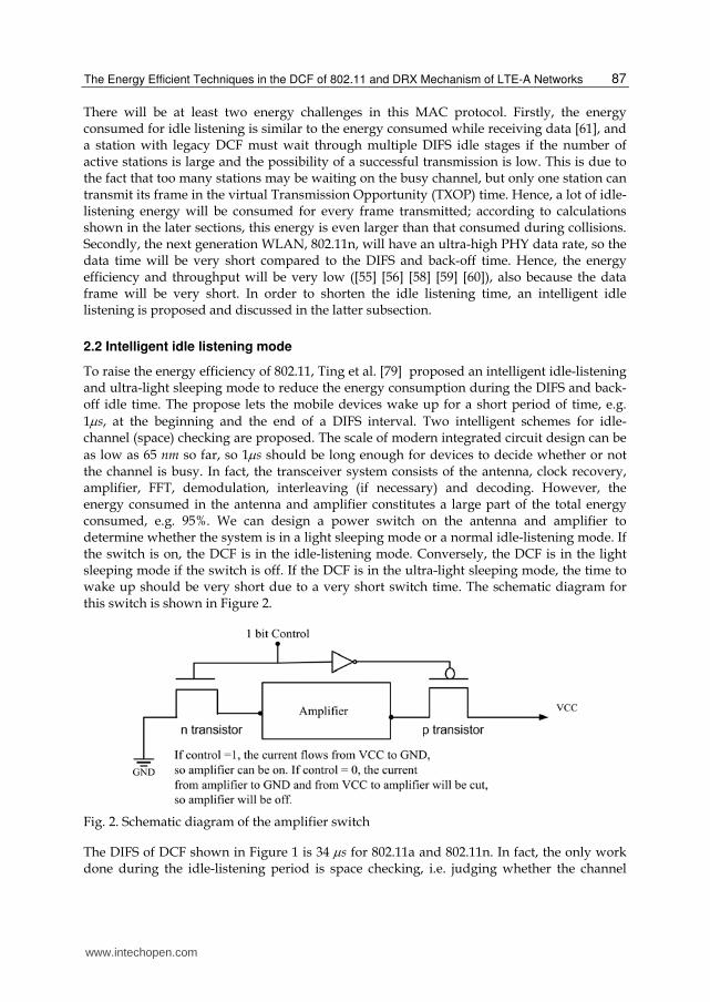
as low as 65 nm so far, so 1s should be long enough for devices to decide whether or not the channel is busy. In fact, the transceiver system consists of the antenna, clock recovery, amplifier, FFT, demodulation, interleaving (if necessary) and decoding. However, the energy consumed in the antenna and amplifier constitutes a large part of the total energy consumed, e.g. 95%. We can design a power switch on the antenna and amplifier to determine whether the system is in a light sleeping mode or a normal idle-listening mode. If the switch is on, the DCF is in the idle-listening mode. Conversely, the DCF is in the light sleeping mode if the switch is off. If the DCF is in the ultra-light sleeping mode, the time to wake up should be very short due to a very short switch time. The schematic diagram for this switch is shown in Figure 2.
Fig. 2. Schematic diagram of the amplifier switch
The DIFS of DCF shown in Figure 1 is 34 s for 802.11a and 802.11n. In fact, the only work done during the idle-listening period is space checking, i.e. judging whether the channel
www.intechopen.com

Energy Efficiency in Communications and Networks
88
being listened to is idle or not. In order to reduce the power consumption, we can use the fact that we do not need to receive the data from the antenna, clock recovery, amplifier, demodulation, FFT and the decoder. Instead, we only need to check the space time in the PHY layer. On the other hand, if the first microsecond is found to be ‘space’, and the last microsecond of DIFS is also found to be ‘space’, then the station can be sure that the DIFS idle time has been long enough. In this situation, the DCF of the station can begin performing the normal back-off operation. The implementation is addressed in the following steps.
Step 1. The beginning of space checking:
The normal procedures of DCF in space checking are antenna receiving, clock recovery, amplifying, demodulation, FFT, and decoding. If the decoding results for the time interval is ‘space’ (no data in), then the DCF of this station can be sure that this is a ‘space’ time interval. We propose two fast schemes for deciding whether or not it is a ‘space’ time interval. Firstly, we can use SNR threshold sensed by a low power sensor. Below this threshold, we can be certain that this is a ‘space’ time interval. Secondly, if the data sub-carriers of the OFDM symbol are ‘space’ (if an OFDM scheme is applied), we can be sure that it is a ‘space’ time interval. However, if only one sub-carrier is non-space for the OFDM symbol, it may be assumed to be interference noise (RFID or microwave radiation) in some
frequency band. Hence, we can verify this ‘space’ time interval within 1 s.
Step 2. Entering the light sleeping mode:
Once the station knows that it is a ‘space’ time interval, the station can enter light sleeping mode by turning off this one bit switch as shown in Figure 2. If we assume
the pre-wakeup time and wake-up time (Amplifier’s stable time) to be w andψ s
respectively, we can set the wake-up timer to (DIFS – w - - 2).
Step 3. The end of space checking:
When the station is awakened by the timer, it will check whether or not the channel is ‘space’. If the channel is idle, the station can perform the back-off operation according to the DCF standard. However, if the channel is not idle, the AP might have sent a series of training symbols to synchronize the destined station after the Point Interframe Space (PIFS) time shown in Figure 1 since the beginning of DIFS. This
preamble time for 802.11a or non-HT 802.11n is around 16 s, which should be long enough for the stations to respond to the AP’s synchronization message. It is the reason why that the station can enter the light sleeping mode without needing to notify the AP that it will enter the Power-Saving Mode (PSM) according to the 802.11 standard. The timing diagram is shown in Figure 3.
The energy consumed during back-off idle listening also plays an important role in determining the power consumption of 802.11. In fact, this intelligent idle-listening scheme can be applied to the back-off. The station can check the space in the beginning of one slot time, and sleep and then be awakened by the sleep timer as the end of this slot time. To lengthen the sleep time, we adopt two-slot time strategy. In other words, the station can check the space in the beginning of the first slot time, and wake up in the end of the second slot time. If the station detects the channel being idle, it could decrease its back-off counter
www.intechopen.com

The Energy Efficient Techniques in the DCF of 802.11 and DRX Mechanism of LTE-A Networks
89
Fig. 3. Intelligent idle-listening in the DIFS period
by two, else it decreases its counter by one. If the beginning of the first slot time is not idle, the station must freeze this counter. It is apparent that if the counter is only one, the station must use the one-slot time strategy. We show this scheme as in Figure 4.
In fact, the idle listening can be divided into several categories. If the station is waiting for the DIFS idle time after a successful transmission between another station and the AP, this idle-listening time is different to the SIFS idle time, which is the turnaround time between a transmitter and a receiver. As the PHY data rate becomes higher, the data time will become shorter. For example, if the frame size is up to 600 octets, and the PHY data rate is up to 600
Mbps, the real data time not including preamble and the PHY header will be as short as 8 s. This data time is even shorter than one slot time under 802.11n. Therefore, it is suggested that the receiver may not apply this efficient power scheme during this critical SIFS time.
Fig. 4. The two-slot time strategy for space checking in the back-off.
2.3 Reference design of the amplifier
2.3.1 The amplifier stable time
A power amplifier is a circuit for converting an input signal and DC power into an output signal of significantly higher output power for transmission and receiving in a radio system; it is an important circuit component used in 802.11 PHY design. In fact, the amplifier under the 802.11 standard is composed of many capacitors, resistors, and other circuits. The charging time of the capacitors is critical to the stable time of the amplifier. From [82], we
can see that the amplifier stable time does not exceed 2 s. Figure 5 illustrates the power amplifier design in [82]. In order to resolve the compatibility issue, we set this amplifier
stable time, i.e. wake-up time w to be 2 s.
www.intechopen.com

Energy Efficiency in Communications and Networks
90
Fig. 5. The reference design of the power amplifier.
2.3.2 The switch time of the amplifier
The switch time of the amplifier is critical to the success of this scheme, so it is essential for us to evaluate it through the analysis and SPICE simulation. If we assume that the total power of the amplifier, P, is 1300 mW, and the total capacitance, C, is about 95 nF, as shown in Figure 5, we can obtain the switch time using Equation (1).
T C V / /( / )I C V P Vdd (1)
We can obtain Equation (2) from Equation (1).
2T C Vdd / P (2)
If Vdd is 3 V and 3.3 V as shown in Figure 5, the switch time is 657 and 796 ns respectively
according to Equation (2). The results obtained from Equations (1) and (2) match with the
results of our SPICE simulation. Hence, if we assume the pre-wakeup time of the amplifier
to be 1 s, this should be long enough to switch this amplifier.
2.4 Energy efficiency of DCF
If we let idlep, recvp, transp, lightp, sleepe, P, R, Rbasic,, , and s denote powers for idle listening, receiving, transmission, light sleeping mode, sleeping mode, packet length (in bits), data rate, basic data rate, all PHY overheads in data, an ACK transmission time, and an OFDM symbol time respectively, we can calculate the energy efficiencies in the MAC layer as shown in the following subsections.
www.intechopen.com

The Energy Efficient Techniques in the DCF of 802.11 and DRX Mechanism of LTE-A Networks
91
2.4.1 Energy efficiency limit of typical DCF
If the number of active stations is very small, the energy consumed in idle listening during the DIFS period and the back-off stage is not large. If there is only one active station, it needs only one DIFS period of idle listening for every frame transmission. If the station is very lucky and sets the back-off counter to zero, we can get the energy efficiency limit of DCF, DCFeff, as shown in Equation (3)
( / )/
[ ( / )/ ) ( ) ( ( / )/ )
peff
p p basic p
P R s s transDCF
P R s s trans idle DIFS SIFS ACK R s s recev (3)
where x denotes the smallest integer larger than x. For example, if the frame size is up to 2304 octets, and the data rate is 54 Mbps for non-HT 802.11n, the DCFeff will be 81%. However, if the data rate is up to 600 Mbps (for MCS 31 PHY mode, 40 MHz bandwidth, number of spatial streams=4, 64 QAM modulation), and the basic data rate is only 60 Mbps (for MCS 24 PHY mode with BPSK modulation), the DCFeff will be only 19.67% because of the short data time if we assume the idle-listening power, transmission power, receiving power, and sleeping power to be 0.89W, 1.4W, 1.02W, and 0.05W respectively, based on [61]. If the number of spatial streams is greater than one, we assume that all energy consumed in idle listening, receiving, and transmission will be multiplied by this number of spatial streams, based on MIMO technology.
2.4.2 Average energy efficiency of typical DCF
It is apparent that if the number of active stations is large, the waiting idle time will increase tremendously, since there will be multiple stages of the DIFS idle time and large contention window sizes. The idle time in the M
tDIFS DIFS, , can be expressed through Equation (4) where M and Ps denote the number of active stations and the possibility of successful transmission respectively, based on Bianchi’s model [35]. Let be the total DIFSM
t DIFS idle time needed for a station to transmit a frame when M active stations are contesting for the channel. It can be calculated using Equation (4).
s sDIFS ((1 P ) /P 1)Mt DIFS M (4)
We can reduce Equation (4) to Equation (5):
sDIFS ( /P ) DIFSMt M (5)
It must be emphasized that Ps is a function of M. If M=1, Ps =1 (perfect channel is assumed), and M
tDIFS =DIFS. However, if M is large, Ps will be very low and MtDIFS will increase
tremendously. Now, we can find the energy consumed during idle listening of DIFS, MeDIFS from Equation (6).
t
M Me pDIFS DIFS Idle (6)
To analyze other power consumption factors such as back-off and collision costs, we express
these two consumption factors in Equations (7) and (8), where , p, R, St, and m denote the probability that a station transmits in a randomly chosen slot time, conditional collision
www.intechopen.com

Energy Efficiency in Communications and Networks
92
probability, data rate, one OFDM symbol time, all PHY overheads and total back-off stages, respectively. Hence, the total energy consumption for one frame transmission, Total_e, including the energy consumed during the DIFS, back-off, collision, receiving, transmission, and SIFS idle listening can be calculated accurately using Equation (9), where Trant and Ackt denote the transmission time of one data frame and an ACK frame respectively, both including the PHY overheads.
1
min 0
(2 )( ((2 ) ) )
1
mmM i
t i
pBackoff W p
p
(7)
3 33( (8 / ) / ) ((1 ) / ) (2 3 (1 ) )
t
M M Mt t s sColl P R S S P P C (8)
( ) ( ) ( )M M Mp t t p t p t tTotal_e Tran Coll Tran Recv Ack Idle DIFS Backoff SIFS (9)
2.4.3 The intelligent idle-listening scheme
If we let st, , and wl denote the space checking time, pre-wakeup time and wake-up time
respectively, the reduced ratio, DIFS, can be expressed through Equation (10), if we assume
that (2 st + w l+ ) < DIFS.
DIFS
(2 ) ( 2 )t l p l t p
p
s w Idle DIFS w s light
DIFS Idle
(10)
Hence, the idle energy, _ MeIn DIFS , consumed in this DIFS by applying this intelligent
scheme, can be expressed through Equation (11).
DIFS_ M Me eIn DIFS DIFS (11)
If lightp is close to idlep, DIFS is not significantly small, as can be seen from Equation (10).
Furthermore, if (2st + + wl) > DIFS, then it is not possible to implement our scheme. Fortunately, we present two intelligent schemes for space checking in this article, and we also propose a quick switch system for wakeup. The time for space checking and the pre-
wakeup time of the amplifier are up to 1 s and 2 s respectively, as shown in the previous section. Hence, this limitation should not pose a problem. Furthermore, the power consumed in the antenna and the amplifier constitutes a large part of the total energy consumed in the transceiver. Hence, lightp should be much smaller than idlep, and not much
larger than sleepp. The DIFS in Equation (10) is about 20% based on our analyses and simulations.
If we apply this intelligent idle listening scheme to the back-off, the reduced ratio, Back-off by means of the two-slot time strategy, can be expressed through Equation (12).
2 (2 2 )
2
t p l t pBack off
p
s Idle slot w s light
slot Idle
(12)
Back-off is about 32.37%. Here, the total time of the two slots is 18 s for the 802.11a and 802.11n.
www.intechopen.com

The Energy Efficient Techniques in the DCF of 802.11 and DRX Mechanism of LTE-A Networks
93
2.5 Simulation and results
2.5.1 Simulation environment
The IEEE 802.11n standard [48] employs multi-input multi-output orthogonal frequency division multiplexing (MIMO-OFDM) transmission techniques to enable high throughput communications, so that a 600 Mbps PHY data rate can be attained through a channel with a bandwidth of 40 MHz [48]. Other features of this new 802.11n standard applicable at both transmitting and receiving ends are a 400 ns short guard interval, transmit beam-forming, HT greenfield format, a maximum HT PSDU length of up to 65535 octets through the aggregation—MSDU (A-MSDU) (or aggregation-MPDU (A-MPDU)) technique, HT-PMD sublayer and space-time block codes (STBC). The PPDU format transmitted by a High Throughput (HT) STA is determined by the TXVECTOR FORMAT, CH_BANDWIDTH, CH_OFFSET and MCS parameters listed in the PHY-TXSTART.request service primitive. There are totally three frame formats; the Non-HT format, the HT mixed format, and the HT greenfield format as shown in Figure 6 [48]. The simulated parameters of 802.11n are listed in Table 1. In this chapter, we select the common HT mixed PPDU format as the simulation target, since it is compatible with non-HT standards, 802.11a/b/g. This mixed format carries a heavier PHY overhead than the non-HT standards. All uplink traffic except ftp, transmission of e-mail attachments, HDTV and video conferencing transmissions have a small frame size, e.g. TCP connections, DNS lookups, MAC layer control frames, and web page requests. We assume that we use the A-MPDU technique to aggregate all these small frames into one large frame with a size of up to 2700 octets.
Fig. 6. The PPDU formats proposed in 802.11n [48].
2.5.2 Power analysis and simulation under DCF
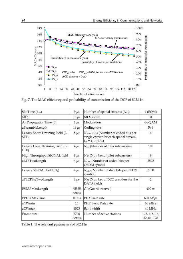
The analysis and simulation results of MAC efficiency and the probability of successful transmission are illustrated in Figure 7, based on the relevant parameters given in Table 1. Figure 7 shows that the results of the analysis are very close to that of the simulations.
www.intechopen.com
Energy Efficiency in Communications and Networks
94
0%
2%
4%
6%
8%
10%
12%
14%
16%
18%
1 8 16 24 32 40 48 56 64 72 80 88 96 104 112 120 128
Number of active stations
MA
C e
ffic
ien
cy
0%
10%
20%
30%
40%
50%
60%
70%
80%
90%
100%
Pro
bab
ilit
y o
f su
cces
sfu
l tr
ansm
issi
on
S_a
S_s
Ps_a
Ps_s
Possibility of success (analysis)
Possibility of success (simulation)
MAC efficency (analysis)MAC efficency (simulation)
CWMin=16, CWMax=1024, frame size=2700 octets
ACK timeout = 0 s
Fig. 7. The MAC efficiency and probability of transmission of the DCF of 802.11n.
SlotTime (tslot) 9 μs Number of spatial streams (NSS) 4 (EQM)
SIFS 16 μs MCS index 31
AirPropagationTime (δ) 1 μs Modulation 64-QAM
aPreambleLength 16 μs Coding rate 5/6
Legacy Short Ttraining Field (L-STF)
8 μs NBPSC (iSS) (Number of coded bits per single carrier for each spatial stream, iSS = 1, ..., NSS)
6
Legacy Long Ttraining Field (L-LTF)
4 μs NSD (Number of data subcarriers) 108
High Throughput SIGNAL field 8 μs NSP (Number of pilot subcarriers) 6
aLTFTwoLength 4 μs NCBPS Number of coded bits per OFDM symbol
2592
Legacy SIGNAL field (H1) 4 μs NDBPS Number of data bits per OFDM symbol
2160
aPLCPSigTwoLength 8 μs NES (Number of BCC encoders for the DATA field)
2
PSDU MaxLength 65535 octets
GI (Guard interval)
400 ns
PPDU MaxTime 10 ms PHY Data rate 600 Mbps
aCWmin 15 PHY Basic Data rate 60 Mbps
aCWmax 1023 Bandwidth 40 MHz
Frame size 2700 octets
Number of active stations 1, 2, 4, 8, 16, 32, 64, 128
Table 1. The relevant parameters of 802.11n
www.intechopen.com
The Energy Efficient Techniques in the DCF of 802.11 and DRX Mechanism of LTE-A Networks
95
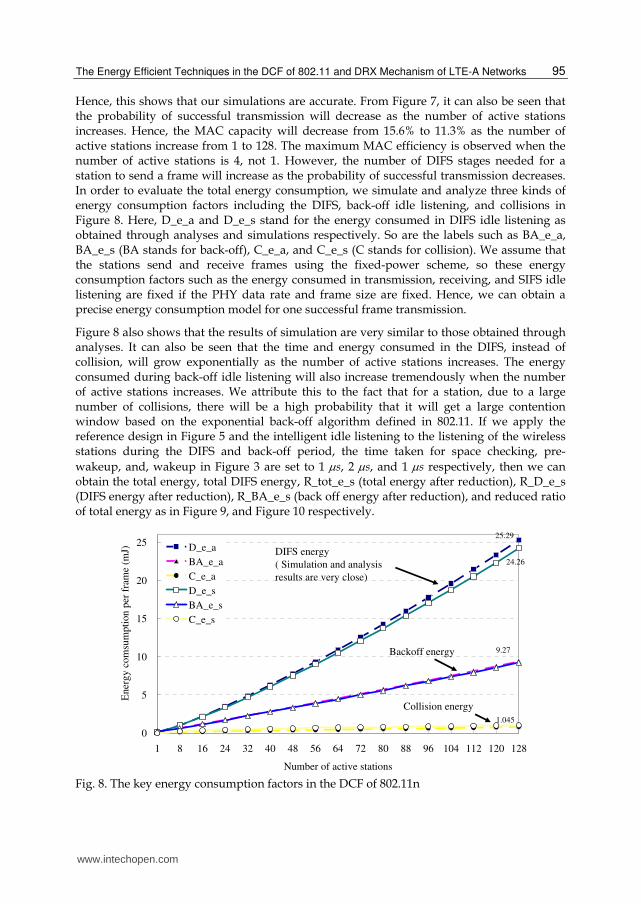
Hence, this shows that our simulations are accurate. From Figure 7, it can also be seen that the probability of successful transmission will decrease as the number of active stations increases. Hence, the MAC capacity will decrease from 15.6% to 11.3% as the number of active stations increase from 1 to 128. The maximum MAC efficiency is observed when the number of active stations is 4, not 1. However, the number of DIFS stages needed for a station to send a frame will increase as the probability of successful transmission decreases. In order to evaluate the total energy consumption, we simulate and analyze three kinds of energy consumption factors including the DIFS, back-off idle listening, and collisions in Figure 8. Here, D_e_a and D_e_s stand for the energy consumed in DIFS idle listening as obtained through analyses and simulations respectively. So are the labels such as BA_e_a, BA_e_s (BA stands for back-off), C_e_a, and C_e_s (C stands for collision). We assume that the stations send and receive frames using the fixed-power scheme, so these energy consumption factors such as the energy consumed in transmission, receiving, and SIFS idle listening are fixed if the PHY data rate and frame size are fixed. Hence, we can obtain a precise energy consumption model for one successful frame transmission.
Figure 8 also shows that the results of simulation are very similar to those obtained through analyses. It can also be seen that the time and energy consumed in the DIFS, instead of collision, will grow exponentially as the number of active stations increases. The energy consumed during back-off idle listening will also increase tremendously when the number of active stations increases. We attribute this to the fact that for a station, due to a large number of collisions, there will be a high probability that it will get a large contention window based on the exponential back-off algorithm defined in 802.11. If we apply the reference design in Figure 5 and the intelligent idle listening to the listening of the wireless stations during the DIFS and back-off period, the time taken for space checking, pre-
wakeup, and, wakeup in Figure 3 are set to 1 s, 2 s, and 1 s respectively, then we can obtain the total energy, total DIFS energy, R_tot_e_s (total energy after reduction), R_D_e_s (DIFS energy after reduction), R_BA_e_s (back off energy after reduction), and reduced ratio of total energy as in Figure 9, and Figure 10 respectively.
0
5
10
15
20
25
1 8 16 24 32 40 48 56 64 72 80 88 96 104 112 120 128
Number of active stations
Ener
gy
co
msu
mpti
on p
er f
ram
e (m
J) D_e_a
BA_e_a
C_e_a
D_e_s
BA_e_s
C_e_s
DIFS energy
( Simulation and analysis
results are very close)
1.045
9.27
24.26
25.29
Backoff energy
Collision energy
Fig. 8. The key energy consumption factors in the DCF of 802.11n
www.intechopen.com
Energy Efficiency in Communications and Networks
96
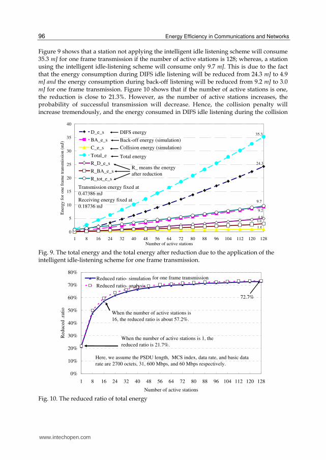
Figure 9 shows that a station not applying the intelligent idle listening scheme will consume 35.3 mJ for one frame transmission if the number of active stations is 128; whereas, a station using the intelligent idle-listening scheme will consume only 9.7 mJ. This is due to the fact that the energy consumption during DIFS idle listening will be reduced from 24.3 mJ to 4.9 mJ and the energy consumption during back-off listening will be reduced from 9.2 mJ to 3.0 mJ for one frame transmission. Figure 10 shows that if the number of active stations is one, the reduction is close to 21.3%. However, as the number of active stations increases, the probability of successful transmission will decrease. Hence, the collision penalty will increase tremendously, and the energy consumed in DIFS idle listening during the collision
0
5
10
15
20
25
30
35
40
1 8 16 24 32 40 48 56 64 72 80 88 96 104 112 120 128Number of active stations
En
erg
y f
or
on
e fr
ame
tran
smis
sio
n (
mJ)
D_e_s
BA_e_s
C_e_s
Total_e
R_D_e_s
R_BA_e_s
R_tot_e_s
Transmission energy fixed at
0.47386 mJ
Receiving energy fixed at
0.18736 mJ
DIFS energy
Total energy
R_ means the energy
after reduction
Back-off energy (simulation)
Collision energy (simulation)
35.3
24.3
9.7
9.2
4.83.0
1.0
Fig. 9. The total energy and the total energy after reduction due to the application of the intelligent idle-listening scheme for one frame transmission.
0%
10%
20%
30%
40%
50%
60%
70%
80%
1 8 16 24 32 40 48 56 64 72 80 88 96 104 112 120 128
Number of active stations
Red
uce
d .
rati
o
Reduced ratio- simulation
Reduced ratio- analysis
72.7%
for one frame transmission
When the number of active stations is
16, the reduced ratio is about 57.2%.
When the number of active stations is 1, the
reduced ratio is 21.7%.
Here, we assume the PSDU length, MCS index, data rate, and basic data
rate are 2700 octets, 31, 600 Mbps, and 60 Mbps respectively.
Fig. 10. The reduced ratio of total energy
www.intechopen.com

The Energy Efficient Techniques in the DCF of 802.11 and DRX Mechanism of LTE-A Networks
97
stage will increase for M active stations. The total energy consumed in the DIFS idle listening is proportional to M and is inversely proportional to the probability of successful transmission according to Equations (4) and (5). The energy consumed in the back-off idle listening will also increase tremendously due to high average contention window according to the exponential back-off function defined in 802.11. So, when the number of active stations increases, the energy consumed in the DIFS and back-off will dominate other power consumption factors and the reduction in total energy will be higher if applying this intelligent scheme. Figure 10 also shows that if the number of active stations is 1, 16, and 128, the total energy consumption for one frame transmission decreases by 21.3%, 57.2%, and 72.7% respectively.
2.6 Related works
2.6.1 The power-saving techniques for stations with no active data transmission
The 802.11 standard employs a different approach to energy conservation with its Power-Saving Mode (PSM) ([45] [46] [47] [48]). The 802.11 provides a mechanism for a power-constrained client to save power by notifying the station to enter the PSM. During the PSM, the station can turn the radio on and off in regular intervals to receive the traffic indication map (TIM) in the beacon broadcast by AP. If the TIM indicates that the AP is buffering frames for the station, the station must retrieve its frame by sending a power-save poll (PS_Poll) to the AP. In fact, if a station first connects with the AP by sending an association request, AP will send an association response with an association ID (AID) to this station. Hence, if there is any data frame destination for this station buffered in AP, the xth bit of TIM will be 1, else it will be 0 where x is equal to the AID of this station. The timing for the stations to wake up and receive the beacon frame is based on the beacon interval field in the received beacon frame. Readers can find that stations can enter sleeping mode and wake up based on this beacon interval. Therefore it can save a lot of energy consumed. Krashinsky et al. [54] evaluates the PSM and found that stations can save the energy consumption up to 90% but stations must pay the delay cost to download the web page. If an idle station with no active data to be uploaded neither to be downloaded, the station will waste the energy consumption on receiving the beacon frame and in switching from sleep to wakeup. In order to solve this tradeoff between energy consumption and traffic delay, they proposed the Bounded Slowdown (BSD) Protocol. Stations can decrease the frequency of wakeup from sleeping mode to receive beacon frames when they are aware of user being occupied in think time in browsing a web page based on this protocol. Stations can save power consumptions with the bounded delay for data frame transmission based on BSD, but its power consumption is still higher than that of PSM. Furthermore, this protocol focuses on the case of long user’s think time when users browse web pages, but this case is rare in real situation. Therefore, they proposed Cross-Layer Power Manager (XEM) to distinguish user think time from inter-arrival time of data frames, in other words, BSD and PSM are used iteratively to save power consumptions. But this burdens the duty of application to achieve this cross-layer communication.
Qiao and Shin [30] proposed Smart Power-Saving Mode (SPMS), an enhanced version of BSD. The key idea of SPMS is that stations listen to the beacon frames broadcast by AP on BSD protocol by static method during the period of idle time, but the evaluation of idle time is dynamic. However, the power consumption of SPSM is still higher than that of PSM, but the reduced delay time is very limited. Compared with BSD and SPMS, Dynamic Beacon Period algorithm (DBP) [71] can be used in any possible idle time because DBP saves power
www.intechopen.com
Energy Efficiency in Communications and Networks
98
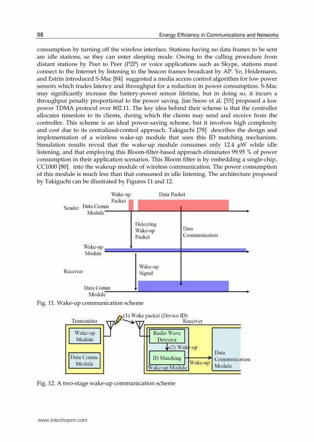
consumption by turning off the wireless interface. Stations having no data frames to be sent are idle stations, so they can enter sleeping mode. Owing to the calling procedure from distant stations by Peer to Peer (P2P) or voice applications such as Skype, stations must connect to the Internet by listening to the beacon frames broadcast by AP. Ye, Heidemann, and Estrin introduced S-Mac [84] suggested a media access control algorithm for low power sensors which trades latency and throughput for a reduction in power consumption. S-Mac may significantly increase the battery-power sensor lifetime, but in doing so, it incurs a throughput penalty proportional to the power saving. Jim Snow et al. [53] proposed a low power TDMA protocol over 802.11. The key idea behind their scheme is that the controller allocates timeslots to its clients, during which the clients may send and receive from the controller. This scheme is an ideal power-saving scheme, but it involves high complexity and cost due to its centralized-control approach. Takiguchi [78] describes the design and implementation of a wireless wake-up module that uses this ID matching mechanism. Simulation results reveal that the wake-up module consumes only 12.4 μW while idle listening, and that employing this Bloom-filter-based approach eliminates 99.95 % of power consumption in their application scenarios. This Bloom filter is by embedding a single-chip, CC1000 [80]. into the wakeup module of wireless communication. The power consumption of this module is much less than that consumed in idle listening. The architecture proposed by Takiguchi can be illustrated by Figures 11 and 12.
Fig. 11. Wake-up communication scheme
Fig. 12. A two-stage wake-up communication scheme
www.intechopen.com

The Energy Efficient Techniques in the DCF of 802.11 and DRX Mechanism of LTE-A Networks
99
This scheme indeed can reduce the power consumption in idle listening, but it needs additional wake-up module for the reception and transmission. Moreover, it needs to send additional packets for wakeup, so it cannot be compatible with the legacy 802.11 stations without wakeup module or the stations not in sleeping mode.
2.6.2 power-saving techniques for stations with active data transmission
The stations without any uploaded packets can use the techniques listed above to save power consumption, but it is useless for the stations with ready packets to be sent. In fact, as stated above, during the back-off stage, only one station will succeed in accessing the channel. The others will wait until the ongoing frame transmission is finished. In 802.11, this waiting time is conveyed by Network Allocation Vector (NAV) and can be obtained from the RTS/CTS frame [45]. Different from the original definition of NAV, the DIFS after a successful frame transmission is added to the NAV to further conserve the energy. Thus, if an RTS frame is heard by certain active stations, these active stations will set their NAVs upon the reception of the MAC header of the RTS frame. They then set their wakeup timers to the NAV minus the time to wake up and enter light sleeping mode. However, if an active station is a hidden terminal, it is deaf to the RTS frame but will hear the CTS frame that responds to the RTS frame. The hidden active station can then set its NAV upon receiving the MAC header of the CTS frame where the NAV includes the DIFS idle time if our intelligent scheme is applied. The scheme is shown in Figure 13.
Fig. 13. The NAV scheme with RTS/CTS in 802.11
This technique has been described in the standard of 802.11. Wang et al. [81] and Sun et al. [83] have illustrated this concept in detail and name this scheme as Demand Wakeup MAC (DW-MAC).
As defined in 802.11 [45], when a station receives a frame that is not destined for it, it will set the NAV according to the duration/ID field (in microseconds) of the received frame plus SIFS, the time to transmit an ACK frame including the PHY overhead, and DIFS minus the wakeup and pre-wakeup time to perform space checking. After that, it sets the wake up timer and then enters light sleeping mode. This NAV scheme is depicted in Figure 14. As shown in Figure 14, other busy listening stations must wake up before the end of the DIFS minus the wake up and pre-wakeup time to perform space checking. If the duration is not specified by the sender, for instance, in power save poll messages, the duration can be estimated as follows:
www.intechopen.com

Energy Efficiency in Communications and Networks
100
( / ) / t t tDuration W R S S S (13)
where W, R, and St denote the length of PLCP Protocol Data Unit (PPDU), the data rate for
PHY header, and one OFDM symbol time respectively, and � denotes the ceiling function. Note that, as shown in Figure 5, the HT-PHY overheads such as high throughput long training field (HT-LTF) depend on the frame format and are included in the PHY sublayer service data units (PSDU) of 802.11n. As a result, the duration given in (13) must be decreased by these HT-PHY overheads.
Fig. 14. A NAV scheme for the frame without RTS/CTS.
3. The LTE-A networks and its energy saving techniques
3.1 Introduction to LTE-A networks and DRX
The evolving fourth-generation (4G) wireless technologies, such as long term evolution (LTE) of Universal Mobile Telecommunications System (UMTS) and WiMAX offer high bandwidth for data transfer. These high data rates over the access part of the network are achieved through the use of higher order modulation, such as 64-quadrature amplitude modulation (QAM), advanced coding techniques, convolutional turbo codes combined with advanced antenna techniques, such as multiple-input multiple-output (MIMO), space-division multiple access (SDMA), and so on. The receivers require computationally complex circuitry that drains the user equipment (UE)’s battery power quickly, thus limiting the use of enriched 4G services. There are various methods, such as DRX in LTE and idle/sleep modes in WiMAX, introduced to improve UE battery lifetime. Furthermore, DRX offers significant improvement with respect to resource utilization, particularly for applications characterized by extended OFF periods. Based on the application type, the DRX parameters are selected so that the energy and resource savings can be maximized. However, the cost associated with enabling DRX modes is that there will be extended delay when the UE needs to transmit/receive data. There may be some Peer-To-Peer (P2P) requests from the distant peer stations and these requests will be delayed from these power saving modes. Therefore there is a need to select the DRX parameters prudently to balance the cost associated with the ensuing limited packet delay and the maximal power saving.
In DRX mode, the UE powers down most of its circuitry when there are no packets to be transmitted or received. During this time UE listens to the downlink (DL) occasionally and may not keep in sync with uplink (UL) transmission depending on whether the UE is
www.intechopen.com

The Energy Efficient Techniques in the DCF of 802.11 and DRX Mechanism of LTE-A Networks
101
registered with an evolved node-B (eNB) in radio resource control (RRC) connected or not RRC idle state [9]. Furthermore, UE has to perform scanning of the neighboring eNB in the event of detecting signal quality degradation with respect to the serving eNB. If the signal quality from one of neighboring eNBs is better than the serving eNB, UE should come out of DRX mode to perform handover (HO) if the UE is in RRC_CONNECTED state or perform a cell reselection if the UE is in RRC_IDLE state. UE may choose to go into DRX once the handover/cell reselection is successfully performed. While in the RRC_IDLE state, UE has to perform tracking area (TA) update whenever a change in TA is detected. In fact, DRX is not a novel idea in Long Term Evolution (LTE) [9] since it has been applied in the 2nd generation system, e.g. the Global System for Mobile Communications (GSM). LTE and LTE-A) are currently two main research focuses, both of which adopt DRX in their specifications. Bontu and Illidge [25] model the LTE DRX and prove that the LTE DRX achieves a more power saving gain over Universal Mobile Telecommunications System (UMTS) DRX at the cost of prolonged delay to wake up. However, as shown in the previous paragraph, some types of traffics such as voices and video are very delay-sensitive and meeting the demand of requirements of Quality of Service (QoS) is essential to these traffics. Owing to the fact that the inter-packet arrival time of these traffics are short, it is impossible for UEs to go to sleep and wake up from this deep sleeping mode. In fact, this transition requires energy and it also takes time, so it needs criteria for these UEs to decide whether go to sleep or not after the expiration of inactive timer (I-Timer) in the DRX cycle. In this chapter, the concept of light sleeping mode [79] is also applied to shorten this wakeup time and reduce transition energy.
Here, the light sleeping mode is defined as that all components in the transceivers of UE are not turned off except the amplifier. This sleeping mode is especially useful when the UE enter into a very short DRX cycle. This light sleeping is distinguished from the definition in other common researches [65]. In fact, some researchers also have the light sleeping mode in their article, but the definition is unclear. Some researchers might regard their light sleeping mode as that stations (used in 802.11) or user equipment (UE, used in LTE) reduce its power consumption by reducing the power level of amplifier in RF for idle listening. They might regard the light sleeping mode as cutting down the circuitry of the transceiver of UE, but the deep sleeping mode is defined in their articles as turning off all the circuitries of UE in transceivers only. In fact, considering the RF power only is impractical in real cases. In this chapter, the powers of circuitries which are cut off include all RF parts except the timer circuitry in deep sleeping mode. The wakeup time from deep sleeping mode also includes the stable time of all wakeup circuitries, the ready time of driver to run in CPU of UEs, and the reception time of important system information of eNB. As to the question that how long of the DRX cycle to sustain the deep sleeping, light sleeping or not entering into sleeping mode in this DRX cycle is the one of key motivations discussed in this chapter.
3.2 The mechanism of DRX in LTE-A networks
3.2.1 DRX
The DRX mechanism in LTE adopts UE-specific parameters determined by the evolved Node B (eNB) (Namely each UE has its own DRX configuration). These parameters are described as follows without taking into account the influence brought by retransmissions and possible measurement gaps.
www.intechopen.com

Energy Efficiency in Communications and Networks
102
- I-Timer: Specifies the number of consecutive physical downlink control channel (PDCCH) subframe(s) during which the receiver will be opened after successfully decoding a PDCCH, indicating an initial uplink (UL) or DL transmission.
- On-Duration Timer (O-Timer): Specifies the number of consecutive PDCCH subframe(s) at the beginning of a DRX cycle.
- DRX cycle: Specifies periodic repetitions of the on-duration. A UE can be configured by two DRX cycles at most (short DRX cycle and long DRX cycle).
The UE monitors PDCCH during the on-duration period, during which the O-Timer is running. If there is no DL transmission for this UE, it will turn off its receiver and enter the sleeping mode instantly after the O-Timer expires. If the PDCCH indicates an initial UL or DL data transmission (here this kind of PDCCH means a valid PDCCH), the ITimer will be started to keep the UE awake to continue monitoring the PDCCH for possible DL traffic. While another valid PDCCH is received during the inactivity period when the I-Timer is running, the I-Timer will be restarted to prolong the inactivity period. However, if the UE has no data transfer in a certain period (i.e. the duration of I-Timer), it will switch off the receiver and won’t switch it on until the next on-duration period. During the sleep period, all DL data for this UE will be buffered in the eNB and this UE won’t be scheduled before the forthcoming on-duration period. The active time of this process stands for the time when the UE keeps monitoring the PDCCH, which includes the time when either the O- or I-Timer is running (on-duration period and inactivity period).
An example mechanism of DRX is shown in Figure 15 [25].
Fig. 15. An example mechanism of DRX.
The critical problem of this DRX mechanism is that if the duration from the expiration of the I-Timer to the next DRX cycle is very short, it is not suitable for the UEs to enter deep sleep in this period due to the energy overheads of this transition and time limitation in DRX cycle. This improper scheduling is illustrated shown in Figure 16.
Fig. 16. An example of improper scheduling in DRX.
www.intechopen.com

The Energy Efficient Techniques in the DCF of 802.11 and DRX Mechanism of LTE-A Networks
103
Figure 16 shows that if the O-timer, I-Timer, and DRX cycle are 2, 6, 16 respectively, the UE is suggested not to enter sleep at the moment of I-Timer expiration if the traffic run in this UE is with delay-sensitive characteristic. If the wakeup time is longer than that of this sleep period, UE may not enter sleep or just go to light-sleeping mode only. In this example, the scheduled sleeping-period is short to 2ms. However, the wakeup time for the UE from deep sleeping mode to active mode may be up to 100ms [62] and the transition energy needed to wakeup may be up to 100mJ if we assume the average power of this transition is up 1W. This energy consumption is much higher than that consumed in idle state for the UE. Furthermore, the traffics such as VoIP might suffer from too numerous delay jitters due to this sleeping action.
3.2.2 PDCCH
The UE will obtain from the PDCCH information for both uplink and downlink resource allocations the UE may use. The Down Link Control Information (DCI) mapped on the PDCCH has different formats and depending on the size DCI is transmitted using one or more Control Channel Elements (CCEs). A CCE is equal to 9 resource element groups. Each group in turn consists of 4 resource elements. The different PDCCH formats are shown in Table 2, where it can be seen that as PDCCH is using QPSK modulation, then a single resource element carries 2 bits and there are 8 bits in a resource element group. The UE will listen to the set of PDCCHs and tries to decode them (checking all formats) in all subframes. The set of PDCCHs to monitor is up to 6 channels. Depending on the network parameterization, some of the PDCCHs are so-called common PDCCHs and may also contain power control information. A subframe in LTE-A consists of ten subframes and each subframe consists of 2 slots. In general, one slot consists of 6-7 OFDM symbols depending on the duration of cyclic prefixes (CP), used to avoid the inter-symbol interference (ISI). If a
short CP, 5.2 s, is used, one slot time consists of 7 OFDM time, but one slot consists of 6
OFDMs if an extended CP, 16.7 s, is used. The structure of a frame in LTE-A network is illustrated in Figure 17.
PDCCH format
Number of CCEs
Number of resource element groups
Number of PDCCH bits
0 1 9 72
1 2 18 144
2 4 36 288
3 8 72 576
Table 2. PDCCH format and its size
Once an UE decodes the PDDCH, in the first 1-3 OFDM symbol of the first slot time of a subframe ( a subframe consists of 2 slot time; the duration of a slot time is 0.5 ms) and finds that there is a DL assignment destined for it. This UE can decode the PDSCH, in the latter part of subframe to receive data. Hence, reception time for one DL assignment in the evaluation of this article is assumed to be 1 ms, a subframe time for a UE. We also assume that the eNB knows the wakeup time of UE according to DRX parameters, so there is no invalid PDCCH reception for UE. Since the reception time of an invalid PDCCH is very
www.intechopen.com

Energy Efficiency in Communications and Networks
104
Fig. 17. The frame structure n LTE-A network.
short (1-3 OFDM time) and the possibility is very small, we ignore the energy to receive invalid PDCCHs in this chapter. Additionally, the UE must listen to the system information broadcast by eNB and send the Channel Quality Indicator (CQI) to eNB periodically, letting eNB have a good channel evaluation for resource scheduling and assignment. Furthermore, it must also send/receive ACK/NAK to/from eNB to indicate the correctness of previous receptions and transmissions. To simplify the evaluation in this chapter, the possible energies consumed listed above are ignored in this chapter.
3.3 The performances of DRX mechanism in LTE and LTE-A networks
3.3.1 Parameters in our proposed scheme
In order to meet the QoS requirement of real-time traffic such as VoIP and video, many constraints have to be obeyed. We list some energy consumptions in Equations (14)-(16)
( ) e DRX t P t pD I Dwakeup D Dwakeup Dwakeup (14)
( ) e DRX t P t pL I Lwakeup L Lwakeup Lwakeup (15)
e DRX PI I I (16)
The related parameters and their estimations are given in Table 3.
It is obvious that in order for UE to enter deep sleeping instead of light sleeping mode, the following conditions must be satisfied: Dwakeupt < IDRX , De < Ie, and De < Le. We can get Equation (17) if the UE must be awake before the start of the next DRX cycle due to the QoS requirement of the traffic.
( ) ( )
( ) 0e DRX P P t P t P
t p t p
S I L D Lwakeup L Dwakeup D
Lwakeup Lwakeup Dwakeup Dwakeup
(17)
If Se > 0 is assumed so that the energy consumed in light sleeping mode is larger than that of deep sleeping mode, then
( ) ( - ) 0
( )
t P t P t p t pDRX
P P
Lwakeup L Dwakeup D Lwakeup Lwakeup Dwakeup DwakeupI
L D
(18)
www.intechopen.com

The Energy Efficient Techniques in the DCF of 802.11 and DRX Mechanism of LTE-A Networks
105
Parameter Description Estimation
TTI Transmission Time Interval 1 ms
DRXt The duration of a DRX cycle in TTI
DRXe(x) Energy consumed in a DRX cycle including a PDCCH message received in xth TTI of O-timer.
DRXLe(x) Energy consumed in a DRX cycle when enters into light sleeping mode including a PDCCH message received in xth TTI of O-timer.
Pe Energy consumed in receiving a PDCCH message within a TTI (Estimation: 1 ms receiving time at estimated receiving power of 1 W)
1 mJ
O O-Timer of a DRX cycle < DRXt
I I-Timer of a DRX cycle < DRXt
IDRX The remaining period after the expiration of O-Timer in a DRX cycle
= DRXtO
DP The average power consumed when UE enters deep sleeping mode
10~50 mW
LP The average power consumed when UE enters light sleeping mode
80~160 mW
Dwakeupt The time needed for UE to wake up from deep sleeping mode to active mode
1~100 ms
Lwakeupt The time needed for UE to wake up from light sleeping mode to active mode
0.001~0.005 ms
Dwakeupp The average power consumed for UE to wake up from deep sleeping mode to active mode
0.5 ~1.5 W
Lwakeupp The average power consumed for UE to wake up from light sleeping mode to active mode
1~1.5 W
It The remaining time for UE to remain in Inactive state after the expiration of I-Timer until the beginning of the next DRX cycle
IP The average power consumed by UE in Inactive state. 400~700 mW
De Energy consumed by UE during deep sleeping and in wake up from deep sleeping mode to active mode
Le Energy consumed by UE during light sleeping and in wake up from light sleeping mode to active mode
Ie Energy consumed by UE in Inactive state until the beginning of the next DRX cycle
Se The gap of the energy consumed by UE between entering light sleeping mode and deep sleeping mode during the interval from the expiration of I-Timer to the beginning of the next DRX cycle.
Eefficiency (The energy consumed by UE to receive one valid PDCCH message in a DRX cycle)/(The total energy consumed by UE in a DRX cycle)
< 1
ELefficiency (The energy consumed by UE to receive one valid PDCCH message in a DRX cycle)/(The total energy consumed by UE in a DRX cycle by entering light sleeping mode)
< 1
Table 3. Symbols and related parameters in the proposed methodology
www.intechopen.com

Energy Efficiency in Communications and Networks
106
Suppose Dp = 30 mW, Lp = 80 mW, Dwakeupp = 500 mW, Lwakeupp = 1300 mW, Dwakeupt = 50 ms, Lwakeupt = 0.003 ms, the condition to meet Se > 0 is IDRX > 500 ms. In other words, the duration from the expiration of I-Timer to the next DRX cycle must be at least 500 ms; otherwise the UE should enter light sleeping mode or not enter sleeping mode at all in order to reduce energy consumption. How can we decide whether UE should enter light sleeping mode or not if Se is negative? The condition is that Le must be less than Ie and Lwakeupt must be less than It. Since a DRX cycle is several TTIs in length, which is much longer than the time to wake up from light sleeping mode, the UE can enter light sleeping mode if It > 0. We devise an algorithm shown in Figure 18 to schedule the sleeping modes of UE based on the above analysis for delay-sensitive traffic.
Fig. 18. Sleeping mode scheduling of UE for delay-sensitive traffic in LTE network
The codes in line 001 to 003 stand for the beginning of a DRX cycle and DRX_timer, O_Timer and I_Timer are initiated by its respective timers. The I_Flag in line 004 used to indicate whether the I-Timer has been initiated or not. The while loop in line 005 stands for a DRX cycle loop and the DRX timer will be decreased by 1 when a TTI elapses shown in lines
001 wakeup at the beginning of a DRX cycle
002 DRX_timer DRX cycle
003 O_Timer O-Timer, I_Timer I-Timer
004 I_Falg False 005 While (DRX_timer > 0) 006 DRX_timer-- 007 If DRX_timer <=0 then 008 Go to 001 /*Initiate another DRX cycle*/ 009 End If 010 While ((O_Timer >0 and not L_Flag) or (I_Timer>0) and I_Flag) 011 If a PDCCH message is received then
012 I_Timer I_Timer-1
013 I_Flag true 014 End If 015 If DRX_Timer--<=0 then 016 Go to 001 017 End If
018 O_Timer O_Timer-1 019 If I_flag then 020 If I_Timer-- <=0 and O_timer<=0 then 021 Break 022 End If 023 End If 024 End While 025 If ((DRX_timer > 0) and (Se > 0)) then 026 Enter deep sleeping mode 027 Break 028 Else 029 Enter light sleeping mode 030 Break 031 End If 032 End While 031 Go to 001
www.intechopen.com

The Energy Efficient Techniques in the DCF of 802.11 and DRX Mechanism of LTE-A Networks
107
006 and 015. If the DRX timer is expired as shown in lines 007 and 016, UE can initiate another DRX cycle. The while loop in line 010 monitors whether the O-Timer or I-Timer has been expired or not. The lines from 025 to 029 determine the Se based on (6) is greater than 0 or not. If Se > 0, the UE can enter into deep sleeping mode, else it must enter into light sleeping mode to save power consumption.
3.3.2 Evaluation environment
The traffic under evaluation is VoIP, following the G711 standard with 20 ms inter-packet
arrival time. In order to meet the QoS requirement that the largest allowable delay is 20 ms,
the UE must serve this traffic within one DRX cycle if we assume the length of a DRX cycle
is also 20 ms. Note that silence suppression and bursty talks between two UEs are not
considered in this study. Further assume that the probability of receiving a valid PDCCH
message during an O-timer period is f(x) = 1/(O) where x is in the range of 0 to O1.
3.4 Performance results
3.4.1 Analysis
We can get the various kinds of energy consumed in one DRX cycle when a UE enters a deep sleeping mode instead of a light sleeping mode, as shown in the following Equations.
( ) ( )[ ( ( 1) ( ( 1)) ( ( 1))) ]e e P P P tDRXL x f x P I O I I O x L DRX I O x TTI (19)
1
0
( ) [ ( / 2 1 / 2)) ( ( / 2 1 / 2))]O
e e e P P tx
DRXL DRXL x P I I O L DRX I O TTI
(20)
( 1)e t P eDRX DRX I TTI P (21)
/efficiency e eEL P DRXL (22)
/efficiency e eE P DRX (23)
( ) /improve e e eE DRX DRXL DRX (24)
The meanings of the symbols in Equations (19)-(24) can be found in Table 2. The improved energy efficiency, Eimprove can refer Equation (24). In this study, we assume that the power in state of waiting for receiving a PDCCH is IP, and the Round Trip Time (RTT) of Hybrid Automatic Repeat Request (HARQ) is ignored to simplify the computation. Assume that the parameters are the same as those used in the previous analysis, the energy efficiency of entering light sleeping mode efficiencyEL and not entering sleeping mode efficiencyEL is shown in Figure 19.
Figure 19 illustrates that the smaller the I-Timer, the higher the energy efficiency will be if a DRX cycle serves only one VoIP traffic with a 20 ms inter-arrival time. However, if the I-Timer is small, the delay for the real-time downlink traffic will be long. The eNB of LTE networks can decide what DRX parameters are to be applied based on the type of the served
www.intechopen.com

Energy Efficiency in Communications and Networks
108
Fig. 19. Energy efficiency in a DRX cycle with VoIP traffic
traffic. The tradeoff between delay and energy efficiency is a critical factor in deciding whether to use the light sleeping mode or deep sleeping mode. We consider VoIP traffic with a Poisson distribution, ( ) !x
f x e x where is the expected number of valid
PDCCH messages in a DRX cycle and the parameters are the same as those used in the previous evaluation. We evaluate the energy consumption of UE and the delay when using light sleeping mode and deep sleeping mode, respectively. The delay and the energy consumption, denoted by DL and EL, can be expressed by Equations (25) and (25), respectively, when UE uses light sleeping mode to reduce energy consumption.
0 0
( ) ( ) ( )!
x
L l lx x
eD f x D x D x
x
(25)
0 0
( ) ( ) ( )!
x
L l lx x
eE f x E x E x
x
(26)
Here DL(x) and EL(x) stand for the delay and energy consumption when UE with the light sleeping scheme receives x PDCCH messages successfully. If we also assume the traffic received by eNB in the interval of a DRX cycle is random, the delay will depend on the time of reception within the DRX cycle. If the first PDCCH message of the traffic in the DRX cycle is received before O-Timer expires, the delay is near minimum, provided the propagation delay is ignored. Hence, the average delay of the traffic can be approximated by Equation (27).
)( 1)1( ) if 0
2 ( )
0 if 0
tDRXt t
t tt Ol
(DRX O DRX Ot x x
DRX DRX xD x
x
(27)
www.intechopen.com

The Energy Efficient Techniques in the DCF of 802.11 and DRX Mechanism of LTE-A Networks
109
As for EL(x), if x is greater than O-Timer, UE must wait for an additional I-Timer to see whether additional PDCCH messages will arrive. Therefore, El(x) can be calculated by Equation (28).
( ) ( ( ( 1))l e P P t eE x P x I I L DRX O x TTI L (28)
If UEs save power consumption by entering deep sleeping mode, several DRX cycles may be needed for UEs to wake up from deep sleeping mode. In this situation, long DRX cycles must be used. One long DRX cycle is equivalent to several short DRX cycles. However, the delay will be much longer than that by entering light sleeping mode only. Under this circumstance, the number of short DRX cycles n must be greater than Dwakeupt/DRXt. The point is that n must be large enough so that the low sleeping power can compensate for the power consumed for the transition from sleeping mode to active mode. We give the delay, and energy consumed, for deep sleeping mode in Equations (29) and (30). We also assume that the )(nDd average number of )(nEd PDCCH messages received from eNB is 1 per short DRX cycle, the same as that in the evaluation of light sleeping mode.
2
1
2( ) ( ( ) ) /
2
n
d t t ti
n nD n DRX O n i DRX n DRX O
n (29)
( ) ( (( ) ) ) /d e p t t t p eE n nP I I TTI DRX n I nDRX TTI Dwakeup D D n (30)
According to Equations (26), (30), (25), (29) and related parameters listed in Table 4, we get the energy consumed and the delay for each valid PDCCH message received as shown in Figures 20 and 21, respectively. Figure 21 shows that if UEs enter deep sleeping mode, the energy consumption (6.69 mJ) is still higher than that if UEs enter light sleeping mode (3.88 mJ) when the number of short DRX cycles is less than 10. However, when n increases above
Parameter Value
Ip 400 mW
Lp 80 mW
TTI 1 ms
DRXt 20 TTI
Dwakeupt 50 ms
Dwakeupp 500 mW
Dp 30 mW
De 25 mJ
O-Timer 2
I-Timer 4
Traffic G711 VoIP
Le 0.006 mJ
Table 4. Evaluation Parameters
www.intechopen.com

Energy Efficiency in Communications and Networks
110
Fig. 20. Energy consumption vs. DRX cycles
Fig. 21. Average delay as a function of DRX cycles
10, the energy consumption of UE entering deep sleeping mode will be lower than that of entering light sleeping mode, but as shown in Figure 21 the delay will increase from 42 ms to 130 ms.
4. Conclusion
The battery endurance is critical to the applications of mobile devices such as PDAs and smart phones. Simulations and analyses showed that if the number of active stations exceeds 16 and 128, the energy consumption can be reduced by over 57.2% and 72.7% respectively, i.e. the battery endurance for the 802.11 can be increased by a factor of two or more by applying this intelligent idle-listening scheme. Even if the number of stations is only one, the total energy consumption can be reduced by 21.7%. The scheme we proposed can be fully compatible with the legacy DCF and there will be no throughput reduction. The two-slot time strategy for space checking applied in the back-off is also a creative method.
www.intechopen.com

The Energy Efficient Techniques in the DCF of 802.11 and DRX Mechanism of LTE-A Networks
111
Furthermore, the model of power analysis presented in this chapter based on Bianchi [13] is a good evaluation scheme for the power consumption to uplink a frame in MAC layer.
In this chapter, we also proposed a light sleeping mode applied in a short DRX cycle for the service of real time or QoS traffics. This study shows that both constraints of wakeup time and energy consumed arisen from deep sleeping mode inhibit the UE from entering into deep sleeping mode. The previous sections show that if the DRX timer is over about 200ms and the traffic can endure the delay up to 200ms,the energy efficiency of entering into the
deep sleeping mode is better than that of entering into the light sleeping mode. However, if the traffics of UE are very delay-sensitive, the huge transition overheads of waking up from deep sleeping mode prohibit the UE from entering into this mode. Hence, in this scenario entering into the light sleeping mode is the only selection to save power consumption and it can increase the power efficiency by 150%(=(35-14)/14×100%) compared with that of not
entering into the any sleeping mode in DRX cycle if only one VoIP traffic is served in a DRX cycle. Our studies also show that if an UE wants to enter into the deep sleeping mode to reduce the power consumption instead of entering into the light sleeping mode, the period of the long DRX cycle must be over ten times of short DRX cycle with 20 TTIs so that it can gain energy efficiency, but at the cost of the delay increasing from 42ms to 140ms. On the contrary, the delay of entering into the light sleeping mode is fixed at 3.88 ms only.
5. Acknowledgment
The authors are deeply grateful for the help of the publishing process manager, Daria Nahtigal, of InTech. With her help, we can print this chapter. Next, we want to thank National Science Council (NSC) for its grant project support in our study. With the support of grant projects of the co-authors, we can devote ourselves to the studies of LTE-A and 802.11.
6. References
[1] 3GPP TR 21.905: “3rd Generation Partnership Project; Technical Specification Group Services and System Aspects; Vocabulary for 3GPP Specifications,” V11.0.1, Dec. 2011.
[2] 3GPP TS 36.211: "3rd Generation Partnership Project; Technical Specification Group Radio Access Network; Evolved Universal Terrestrial Radio Access (E-UTRA); Physical Channels and Modulation,” V10.4.0, Dec. 2011.
[3] 3GPP TS 36.212: "3rd Generation Partnership Project; Technical Specification Group Radio Access Network; Evolved Universal Terrestrial Radio Access (E-UTRA); Multiplexing and channel coding,” V10.4.0, Dec. 2011.
[4] 3GPP TS 36.213: "3rd Generation Partnership Project; Technical Specification Group Radio Access Network; Evolved Universal Terrestrial Radio Access (E-UTRA); Physical layer procedures,” V10.4.0, Dec. 2011.
[5] 3GPP TS 36.307: "3rd Generation Partnership Project; Technical Specification Group Radio Access Network; Evolved Universal Terrestrial Radio Access (E-UTRA); Requirements on User Equipments (UEs) supporting a release-independent frequency band,” V10.2.0, Sep. 2011.
www.intechopen.com

Energy Efficiency in Communications and Networks
112
[6] 3GPP TR 36.814, “Further advancements for E-UTRA physical layer aspects,” v9.0.0 (Release 9), Mar. 2010.
[7] 3GPP TS 23.234, "Technical Specification Group Services and System Aspects; 3GPP System to Wireless Local Area Network (WLAN) Interworking; System Description," V10.3.0 (Release 10), Dec. 2011.
[8] 3GPP TS 25.304, "User Equipment (UE) procedures in idle mode and procedures for cell reselection in connected mode," V10.3.0 (Release 10), Dec. 2011.
[9] 3GPP TS 25.331, “Radio Resource Control (RRC) protocol specification,” V11.0.0 (Release 11), Jan. 2012.
[10] 3GPP TS 36.300, "Evolved Universal Terrestrial Radio Access (EUTRA) and Evolved Universal Terrestrial Radio Access Network (EUTRAN); Overall description; Stage 2." V9.0.0 (Release 9), Dec. 2009.
[11] 3GPP TS 36.304, “E-UTRA: User Equipment Procedures in Idle Mode,” Rel. 8, v. 8.2.0, May 2008.
[12] 3GPP TS 36.321, Evolved Universal Terrestrial Radio Access (EUTRA); Medium Access Control (MAC) protocol specification, V10.4.0 (Release 10), Dec. 2011.
[13] 3GPP TSG RAN WG2 meeting 57bis, R2-071285, DRX parameters in LTE-A, Mar. 2007. [14] 3GPP, “3rd Generation Partnership Project; Technical Specification Group Radio Access
Network; Evolved Universal Terrestrial Radio Access (E-UTRA) and Evolved Universal Terrestrial Radio Access Network (E-UTRAN); Overall description; Stage 2,” Technical Specification 3GPP TS 36.300, v. 8.5.0, May 2009.
[15] 3GPP, “3rd Generation Partnership Project; Technical Specification Group Radio Access Network; Evolved Universal Terrestrial Radio Access (E-UTRA) Radio Resource Control (RRC); Protocol specification,” Technical Specification 3GPP TS 36.331, v. 8.5.0, May 2009.
[16] 3rd Generation Partnership Project (3GPP); Requirements for Evolved UTRA (EUTRA) and Evolved UTRAN (E-UTRAN), http://www.3gpp.org/ftp/Specs/html-info/25913.htm.
[17] 3rd Generation Partnership Project (3GPP); Technical Specification Group Radio Access Network; Physical Layer Aspects for Evolved UTRA,
http://www.3gpp.org/ftp/Specs/html-info/25814.htm. [18] 3rd Generation Partnership Project; Technical Specification Group Radio Access
Network; Physical Layer Aspects for Evolved Universal Terrestrial Radio Access (UTRA), 3GPP TR 25.814 V7.1.0, Sept. 2009.
[19] 3rd Generation Partnership Project; Technical Specification Group Radio Access Network; Evolved Universal Terrestrial Radio Access (E-UTRA); User Equipment (UE) radio transmission and reception (Release 8), 3GPP TS 36.101 v8.7.0, Sept. 2009.
[20] A. Saleh, “Frequency independent and frequency dependent nonlinear models of TWT amplifiers,” IEEE Transactions on Communications 1981, 29(1), pp. 1715-1720.
[21] A.-K. Salkintzis and C. Chamzas, “Performance Analysis of a Downlink MAC Protocol with Power-Saving Support,” IEEE Transactions on Vehicular Technology, May 2000, 49(3), pp. 1029-1040.
[22] K. Ahoi, J. Puttonen,T. Henttonen, and L. Dalsgaard, “Channel Quality Indicator Preamble for Discontinuous Reception,” Proc. Vehicular Technology Conference 2010 (VTC 2010-Spring).
www.intechopen.com

The Energy Efficient Techniques in the DCF of 802.11 and DRX Mechanism of LTE-A Networks
113
[23] B. Otal and J. Habetha, “Power saving efficiency of a novel packet aggregation scheme for high-throughput WLAN stations at different data rates,” Proc. Vehicular Technology Conference, Vol. 3, pp. 2041–2045, , May/June 2005.
[24] L. Bononi, M. Conti, and L.Donatiello, “A distributed contention control mechanism for power saving in random-access ad-hoc wireless local area networks,” Mobile Multimedia Communications, pp. 114–123, November 1999.
[25] C. Bontu and E. Illidge, "DRX Mechanism for Power Saving in LTE-A,” J. IEEE Communication Magazine, 47, pp. 48-55, Jun. 2009.
[26] C. Ciochina, D. Mottier and H. Sari, "An Analysis of Three Multiple Access Techniques for the Uplink of Future Cellular Mobile Systems,” European Transactions on Telecommunications, 19(5), pp. 58– 588, August 2008.
[27] CDPD Forum, Cellular Digital Packet Data System Specification: Release 1.1. Technical report, CDPD Forum, Inc., January 1995.
[28] C.-H. Yeh, “Interference-aware Energy-efficient MAC Protocols for Sensor and Wireless Pervasive Networks,” Proc. IEEE SMC, vol. 1, pp. 181–186, Oct. 8-11, 2006.
[29] D. Jiang, H. Wang, E. Malkamki, and E. Tuomaala, “Principle and Performance of Semi-Persistent Scheduling for VoIP in LTE-A System,” Proc. International Conference on Wireless Communications, Networking and Mobile Computing (WiCom’07), pp. 2861–2864, September 2007.
[30] D. Qiao and K.G. Shin, “Smart power-saving mode for IEEE 802.11 wireless LANs,” Proc. Annual Joint Conference of the IEEE Computer and Communications Societies (INFOCOM 2005), Miami, FL, March 13–17, 2005.
[31] Evaluation Methodology Document (EMD), IEEE Standard 802.16m-08/004r5, 2009. [32] F. Boye, P. Rost, and G. Fettweis, ‘‘Adaptive radio resource management for a cellular
system with fixed relay nodes,’’ Proc. IEEE Personal, Indoor and Mobile Radio Communications (PIMRC’08), pp. 1–5, Sept. 2008.
[33] F.W Li, Y.Q. Zhang, L.W. Li, “Enhanced discontinuous reception mechanism for power saving in TD-LTE-A,” Proc. IEEE International Conference on Computer Science and Information Technology (ICCSIT), 2010.
[34] G. Song and Y. Li, “Cross-layer Optimization for OFDMA Wireless Networks-Part II: Algorithm Development,” IEEE Wireless Communication, 4, pp. 625–634, Mar. 2005.
[35] G. Bianchi, “Performance Analysis of the IEEE 802.11 Distributed Coordination Function,” IEEE Journal On Selected Areas In Communications, Vol. 18, No. 3, March 2000.
[36] G. S. Kim, Y. H. Je, and S. Kim, “An adjustable power management for optimal power saving in LTE-A terminal baseband modem,” IEEE Transactions on Consumer Electronics, 55(4), pp. 1847 – 1853, 2009.
[37] H. Ekström, A. Furusk¨ar, J. Karlsson, M. Meyer, S. Parkvall, J. Torsner, and M. Wahlqvist, “Technical solutions for the 3G long term evolution,” IEEE Communications Magazine, 44, pp. 38–45, March 2006.
[38] H. Holma and A. Toskala, WCDMA for UMTS, Third Ed., Wiley, 2004. [39] H. Kaaranen, A. Ahtiainen, L. Laitinen, S. Naghian, and V. Niemi, UMTS Networks,
Second Ed., Wiley, 2005. [40] H. Sari, G. Karam, and I. Jeanclaude, “Transmission Techniques for Digital Terrestrial
TV Broadcasting,” IEEE Communication. Magazine, 33(2), pp. 100–109, Feb. 1995. [41] H. Wu and T. Haustein, “Energy and Spectrum Efficient Transmission Modes for the
3GPP-LTE-A UL,” Proc. IEEE PIMRC, pp. 1–5, Sept. 2007.
www.intechopen.com

Energy Efficiency in Communications and Networks
114
[42] H. Y. Lei, Performance Analysis of Power Management in WLAN and UMTS, PH.D. Thesis, North Carolina State University, 2005.
[43] B. Huang, H. Tian, L. Chen, and J. Zhu, “DRX-aware Scheduling Method for Delay-Sensitive Traffic,” IEEE Communications Letters, 14(12), pp. 1113-1115, 2010.
[44] Chlamtac, Y. Fang, and H. Zeng, “Call Blocking Analysis for PCS Networks under General Cell Residence Time,” IEEE Wireless Communications and Networking Conference, September 1999.
[45] IEEE standard for Wireless LAN-Medium Access Control and Physical Layer Specification, P802.11, November 1997.
[46] IEEE 802.11 WG, part 11a/11b/11g, Wireless LAN Medium Access Control (MAC) and Physical Layer (PHY) specifications, Standard Specification, IEEE, 1999.
[47] IEEE 802.11e, Wireless LAN Medium Access Control (MAC) and Physical Layer (PHY) specification: Medium Access Control (MAC) Enhancements for Quality of Service (QoS), November 2005.
[48] IEEE P802.11n™/D3.0, “Draft Amendment to STANDARD: Wireless LAN Medium Access Control (MAC) and Physical Layer (PHY) specifications: Enhancements for Higher Throughput,” Sept, 2007.
[49] J. Lim, H.G. Myung, and D.J. Goodman, “Proportional Fair Scheduling of Uplink Single-Carrier FDMA Systems,” Proc. 7th Annual IEEE International Symposium on Personal, Indoor and Mobile Radio Communications (PIMRC 06), Helsinki, Finland, Sept. 2006.
[50] J. Puttonen, T. Henttonen, N. Kolehmainen, K. Aschan, M. Moisio, and P. Kela, “Voice-over-IP Performance in UTRA Long Term Evolution Downlink,” Proc. IEEE Vehicular Technology Conference, (VTC’S08), pp. 2502-2506, May 2008.
[51] J. Wiqard and T. Kolding, "On the User Performance of LTE-A UE Power Savings Schemes with Discontinuous Reception in LTE-A,” Proc. IEEE International Conference on Communications Workshops, 2009.
[52] J.-H. Yeh et al., “Performance Analysis of Energy Consumption in 3GPP Networks,” Proc. Wireless Telecommun. Symp., pp. 67–72, May 2004.
[53] J. Snow, W.C. Feng, W.C. Feng, “Implementing a low power tdma protocol over
802.11,” Proc. WCNC, pp. 75-80, 2005. [54] R. Krashinsky and H. Balakrishnan, “Minimizing energy for wireless web access with
bounded slowdown,” Wireless Network, 11(1-2), pp. 135-148, 2005. [55] K.C. Ting and F.P. Lai, “Design and Analysis of grouping-based DCF (GB-DCF) scheme
for the MAC layer enhancement of 802.11 and 802.11n,” Proc. ACM/IEEE International Symposium on Modeling, Analysis and Simulation of Wireless and Mobile Systems, 2006.
[56] K.C. Ting and F.P. Lai, “Design and Analysis of grouping-based DCF (GDCF) scheme for the MAC layer enhancement of 802.11,” Proc. Globecom, 2006.
[57] K.C. Ting, F.C. Kuo, B.J. Hwang, H.C. Wang, and C.C. Tseng, “A Power-Saving and Robust Point Coordination Function for the transmission of VoIP over 802.11,” Proc. IEEE International Symposium on Parallel and Distributed Processing with Applications, Taipei, Taiwan, September 6-9, 2010.
[58] K.C. Ting, F.C. Kuo, B.J. Hwang, H.C. Wang, and F.P. Lai, “An accurate power analysis model based on MAC layer for the DCF of 802.11n,” Proc. IEEE
www.intechopen.com
The Energy Efficient Techniques in the DCF of 802.11 and DRX Mechanism of LTE-A Networks
115
International Symposium on Parallel and Distributed Processing with Applications, Taipei, Taiwan, Sept. 6-9, 2010.
[59] K.C. Ting, H.C. Wang, C.C. Tseng, and F.C. Kuo, “Energy-Efficient DRX Scheduling for QoS Traffic in LTE Networks,” Proc. IEEE ISPA, Busan, Korea, 26-28 May, 2011.
[60] L. Zhou, H.B. Xu and H. Tian, "Performance Analysis of Power Saving Mechanism with Adjustable DRX Cycles in 3GPP LTE-A,” Proc. IEEE 68th Vehicular Technology Conference (VTC), IEEE Press, pp. 1-5, Oct. 2008.
[61] L.M. Feeney and M. Nilsson, “Investigating the Energy Consumption of a Wireless Network Interface in an Ad Hoc Networking Environment,” Proc. IEEE INFOCOM, pp. 1548-1557, 2001.
[62] M. Anand, E. Nightingale, and J. Flinn, “Self-tuning wireless network power management,” Wireless Networks, 11(4), pp. 451-469, Jul. 2005.
[63] M. Andrews, K. Kumaran, K. Ramanan, A. Stolyar, P. Whiting, and R. Vijayakumar, “Providing quality of service over a shared wireless link,” IEEE Communication Magazine, 39(2), pp. 150-154, 2001.
[64] M. Keating, D. Flynn, R. Aitken, A. Gibbons, and K. Shi, Low Power Methodology Manual, Springer, 2007.
[65] Nokia, R2-071285, DRX parameters in LTE, March 2007 [66] P. Kela, J. Puttonen, N. Kolehmainen, T. Ristaniemi, T. Henttonen, and M. Moisio,
“Dynamic Packet Scheduling Performance in UTRA Long Term Evolution Downlink,” Proc. International Symposium on Wireless Pervasive Computing (ISWPC), May 2008.
[67] X. Perez-Costa and D. Camps-Mur, “APSM: bounding the downlink delay for 802.11 power save mode,” Proc. IEEE International Conference on Communications (ICC 05), pp. 3616–3622, 2005.
[68] R. Dinis, D. Falconer, C.T. Lam, and M. Sabbaghian, “A Multiple Access Scheme for the Uplink of Broadband Wireless Systems,” Proc. IEEE GLOBECOM, Dec. 2004 (Dallas, TX), 6, pp. 3808–3812.
[69] R. Schoenen, R. Halfmann, and B. H. Walke, ‘‘MAC performance of a 3GPP-LTE-A multihop cellular network’’, Proc. IEEE Int. Conf. Communications (ICC’08), pp. 4819–4824, May 2008.
[70] R. van Nee and R. Prasad, OFDM for Wireless Multimedia Communications, Artech House, 2000.
[71] S. Nath, Z. Anderson, and S. Seshan, “Choosing beacon periods to improve response times for wireless HTTP clients,” Proc. ACM International Workshop on Mobility Management and Wireless Access, pp. 43-50, Philadelphia, PA, Sept. 26-Oct. 1, 2004.
[72] S.R. Yang and Y.B. Lin, "Modeling UMTS Discontinuous Reception Mechanism,” IEEE Transactions on Wireless Communications, vol. 4, pp. 312-319, Jan. 2005.
[73] S.R. Yang, "Dynamic Power Saving Mechanism for 3G UMTS System,” J. Mobile Networks and Applications, 2, pp. 5-14, Jan. 2007.
[74] S.R. Yang, S.Y. Yan, and H.N. Hung, "Modeling UMTS Power Saving with Bursty Packet Data Traffic,” J. IEEE Transactions on Mobile Computing, 6, pp. 1398-1409, Dec. 2007.
[75] S. Yang, M. Yoo, and Y. Shin, "An Adaptive Discontinuous Reception Mechanism Based on Extended Paging Indicator for Power Saving in UMTS,” Proc. IEEE 64th Vehicular Technology Conference (VTC), pp. 1-5, Sept. 2006.
www.intechopen.com

Energy Efficiency in Communications and Networks
116
[76] S.J. Kwon, Y.W. Chung, and D.K. Sung, “Queueing Model of Sleep- Mode Operation in Cellular Digital Packet Data,” IEEE Transactions on Vehicular Technology, 52(4), pp. 1158–1162, July 2003.
[77] T. Kolding, J. Wigard, and L. Dalsgaard, “Balancing Power Saving and Single User Experience with Discontinuous Reception in LTE-A,” Proc. IEEE International Symposium on Wireless Communication Systems (ISWCS’08), October 2008.
[78] T. Takiguchi, S. Saruwatari, T. Morito, S. Ishida, M. Minami, and H. Morikawa, “A Novel Wireless Wake-Up Mechanism for Energy-Efficient Ubiquitous Networks,” Proc. IEEE Communications Conferences, pp. 1–5, 2009.
[79] K.C. Ting, H.C. Lee, H.H. Lee, and F.P. Lai, “An idle listening-aware energy efficient scheme for the DCF of 802.11n,” IEEE Transactions on Consumer Electronics, 55(2), pp. 447-454, 2009.
[80] Texas Instrument, http://www.cse.ohio-state.edu/siefast/nest/nest_webpage/ datasheet/Chipcon%20-%20CC1000%20Data%20Sheet%20v2.1.pdf, Chipcon AS SmartRF, CC1000 Preliminary Datasheet (rev. 2.1), April 19, 2002.
[81] X. Wang, J. Yin, and D.P. Agrawal, “Analysis and optimization of the energy efficiency in the 802.11 DCF,” Journal of Mobile Networks and Applications, 11(2), pp. 279–286, 2006.
[82] Winspring Wireless Technologies, WS9901 2.4GHz ISM Band Linear Power Amplifier, WS9901spec.pdf.
[83] Y. Sun, S. Du, O. Gurewitz, and D.B. Johnson, “DW-MAC: A Low Latency, Energy Efficient Demand-Wakeup MAC Protocol for Wireless Sensor Networks,” Proc. MobiHoc’08, Hong Kong, China, May 26–30, 2008.
[84] W. Ye, J. Heidemann, and D. Estrin, “An energy-efficient MAC protocol for wireless sensor networks,” Proc. IEEE INFOCOM, pp. 1567-1576, 2002.
[85] C.H. Yeh, “Interference-Aware energy-efficient MAC protocols for sensor and wireless pervasive networks,” Proc. IEEE International Conference on Systems, Man and Cybernetics, pp. 181-186, 2006.
[86] Z. Zhou, X. Xiang, X. Wang, and J. Pan, “An energy-efficient data-dissemination protocol in wireless sensor networks,” Proc. International Symposium on a World of Wireless, Mobile and Multimedia Networks, pp. 10-22, 2006.
www.intechopen.com
Energy Efficiency in Communications and NetworksEdited by Dr. Sameh Gobriel
ISBN 978-953-51-0482-7Hard cover, 142 pagesPublisher InTechPublished online 04, April, 2012Published in print edition April, 2012
InTech EuropeUniversity Campus STeP Ri Slavka Krautzeka 83/A 51000 Rijeka, Croatia Phone: +385 (51) 770 447 Fax: +385 (51) 686 166www.intechopen.com
InTech ChinaUnit 405, Office Block, Hotel Equatorial Shanghai No.65, Yan An Road (West), Shanghai, 200040, China
Phone: +86-21-62489820 Fax: +86-21-62489821
The topic of "Energy Efficiency in Communications and Networks" attracts growing attention due to economicaland environmental reasons. The amount of power consumed by information and communication technologies(ICT) is rapidly increasing, as well as the energy bill of service providers. According to a number of studies,ICT alone is responsible for a percentage which varies from 2% to 10% of the world power consumption. Thus,driving rising cost and sustainability concerns about the energy footprint of the IT infrastructure. Energy-efficiency is an aspect that until recently was only considered for battery driven devices. Today we see energy-efficiency becoming a pervasive issue that will need to be considered in all technology areas from devicetechnology to systems management. This book is seeking to provide a compilation of novel researchcontributions on hardware design, architectures, protocols and algorithms that will improve the energyefficiency of communication devices and networks and lead to a more energy proportional technologyinfrastructure.
How to referenceIn order to correctly reference this scholarly work, feel free to copy and paste the following:
Kuo-Chang Ting, Hwang-Cheng Wang, Fang-Chang Kuo, Chih-Cheng Tseng and Ping Ho Ting (2012). TheEnergy Efficient Techniques in the DCF of 802.11 and DRX Mechanism of LTE-A Networks, Energy Efficiencyin Communications and Networks, Dr. Sameh Gobriel (Ed.), ISBN: 978-953-51-0482-7, InTech, Available from:http://www.intechopen.com/books/energy-efficiency-in-communications-and-networks/a-light-sleeping-mode-design-for-the-energy-efficiency-of-802-11-and-lte-a-

© 2012 The Author(s). Licensee IntechOpen. This is an open access articledistributed under the terms of the Creative Commons Attribution 3.0License, which permits unrestricted use, distribution, and reproduction inany medium, provided the original work is properly cited.