Embed Size (px)
Citation preview
The Emissivity Profiles of AGN Accretion Discs
Dan WilkinsInstitute of Astronomy, University of Cambridge
Supervisor: Andy Fabian
High Energy View of Accreting Objects, Crete 2010
1. Concept of emissivity profiles
• So what?
2. Determination from observed spectra
• 1H 0707-495
3. Test with self-consistent XSPEC model
4. Theoretical emissivity profiles
• Link to source parameters
Outline
2
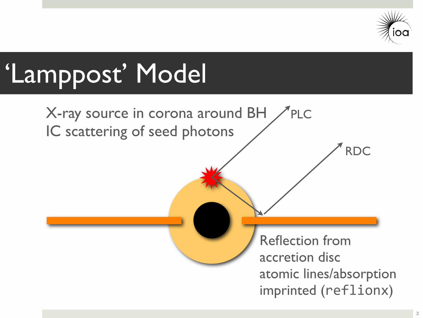
‘Lamppost’ Model
3
PLC
RDC
X-ray source in corona around BHIC scattering of seed photons
Reflection from accretion discatomic lines/absorption imprinted (reflionx)
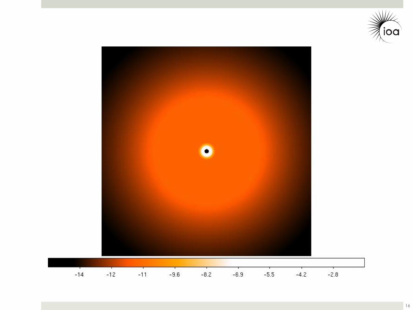
Emissivity Profile
4
• Reflected power per unit area from disc.
• Flux received at point on disc falls off with distance from X-ray source.
1e-05
0.0001
0.001
0.01
0.1
1
10
0.1 1 10 100r
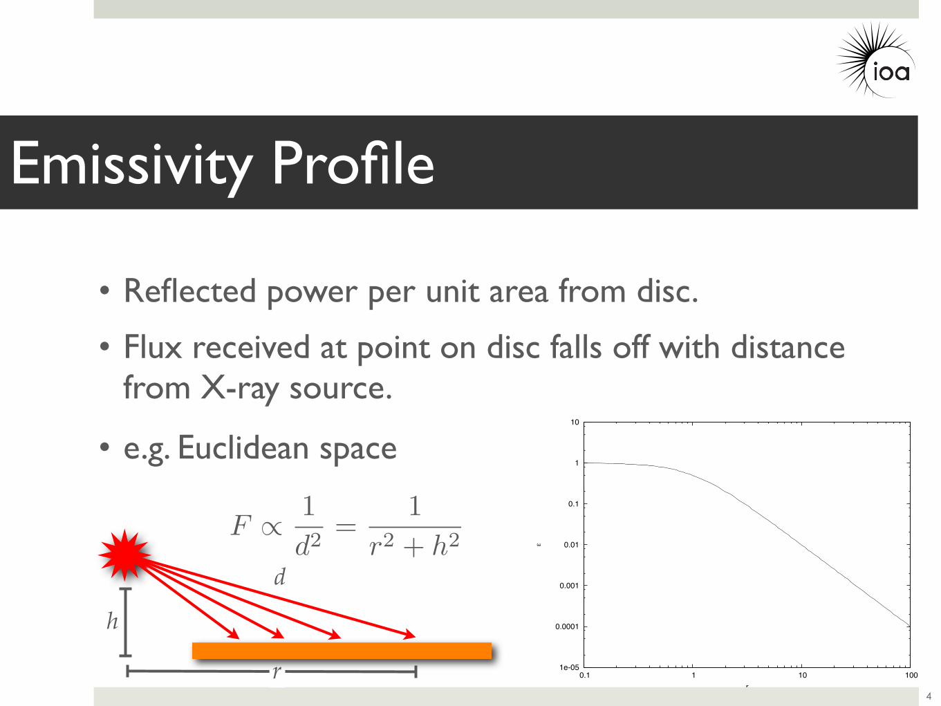
Emissivity Profile
4
• Reflected power per unit area from disc.
• Flux received at point on disc falls off with distance from X-ray source.
F ∝ 1d2
=1
r2 + h2
d
h
• e.g. Euclidean space
r
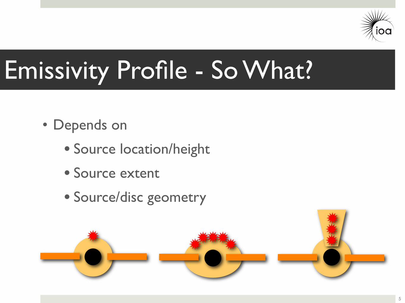
Emissivity Profile - So What?
5
• Depends on
• Source location/height
• Source extent
• Source/disc geometry
• Typically assume a (broken) power law emissivity profile.
Emissivity Profiles from Spectra
6
(r) ∝ r−α
• Typically assume a (broken) power law emissivity profile.
Emissivity Profiles from Spectra
6
(r) ∝ r−α
• Instead, can we determine the emissivity from observed spectra?
• Constrain properties of X-ray source...
1 100.5 2 5
12
3
ratio
Energy (keV)
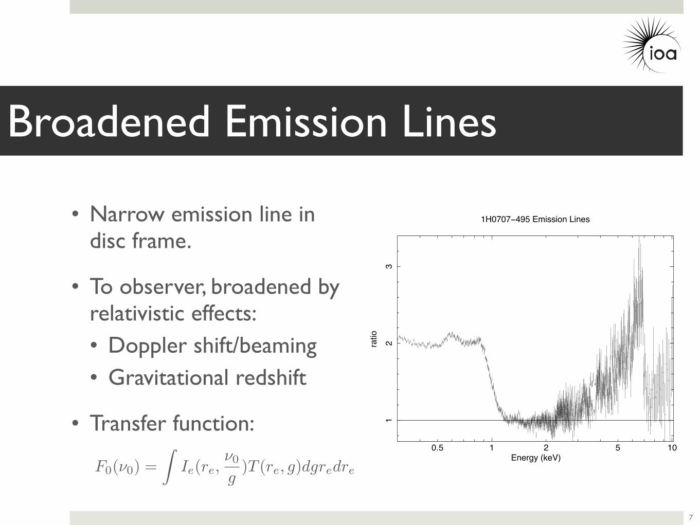
1H0707 495 Emission Lines• Narrow emission line in disc frame.
• To observer, broadened by relativistic effects:• Doppler shift/beaming• Gravitational redshift
• Transfer function:
Broadened Emission Lines
7
F0(ν0) =
Ie(re,ν0
g)T (re, g)dgredre
105
050
010
00
norm
aliz
ed c
ount
s s
1 keV
1
Energy (keV)
Broadened Emission Lines
8
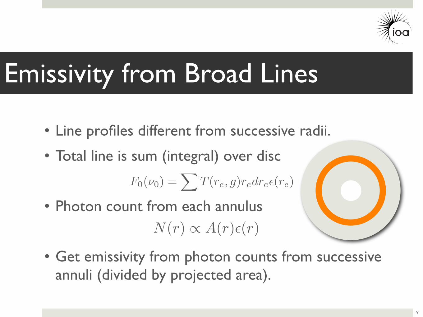
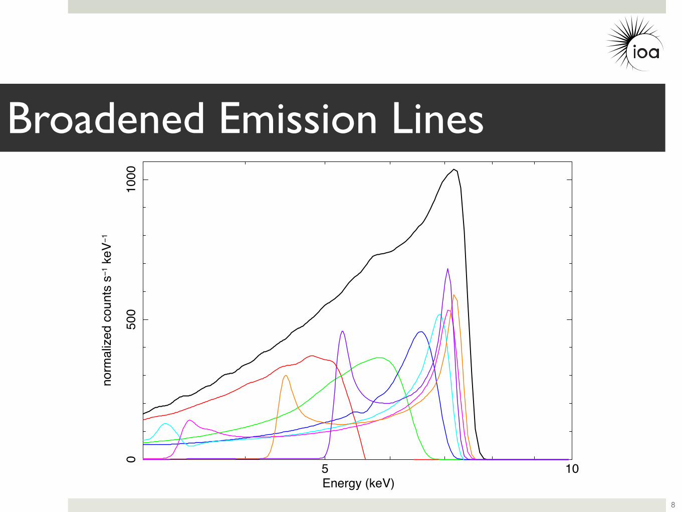
• Line profiles different from successive radii.
• Total line is sum (integral) over disc
• Photon count from each annulus
• Get emissivity from photon counts from successive annuli (divided by projected area).
Emissivity from Broad Lines
9
F0(ν0) =
T (re, g)redre(re)
N(r) ∝ A(r)(r)
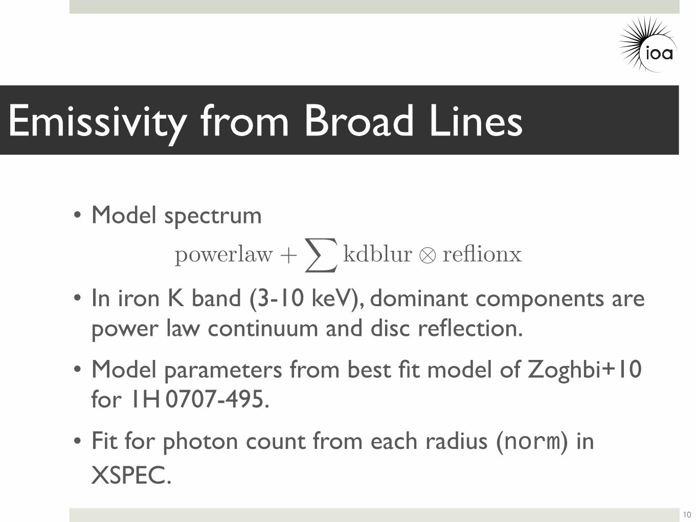
• Model spectrum
• In iron K band (3-10 keV), dominant components are power law continuum and disc reflection.
• Model parameters from best fit model of Zoghbi+10 for 1H 0707-495.
• Fit for photon count from each radius (norm) in XSPEC.
Emissivity from Broad Lines
10
powerlaw +
kdblur⊗ reflionx
10 3
0.01
norm
aliz
ed c
ount
s s
1 keV
1
data and folded model
105
0.8
1
1.2
ratio
Energy (keV)drw 20 May 201
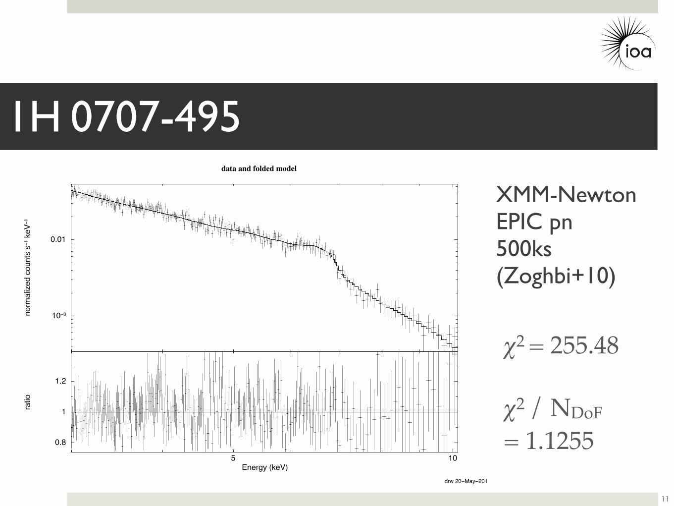
χ2 = 255.48
χ2 / NDoF = 1.1255
1H 0707-495
11
XMM-NewtonEPIC pn500ks(Zoghbi+10)
! = 3.3
! = 6
" /
arbi
trar
y u
nits
10#10
10#9
10#8
10#7
10#6
10#5
10#4
10#3
0.01
r / RG
1 10 100
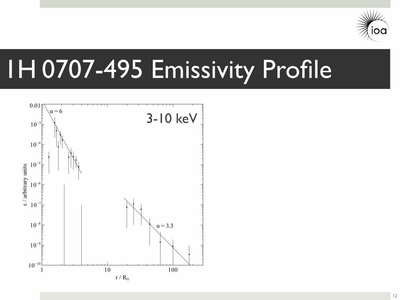
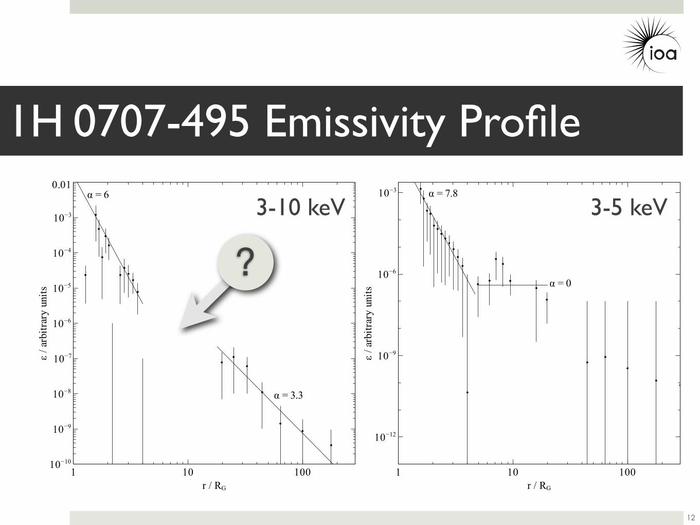
1H 0707-495 Emissivity Profile
12
3-10 keV
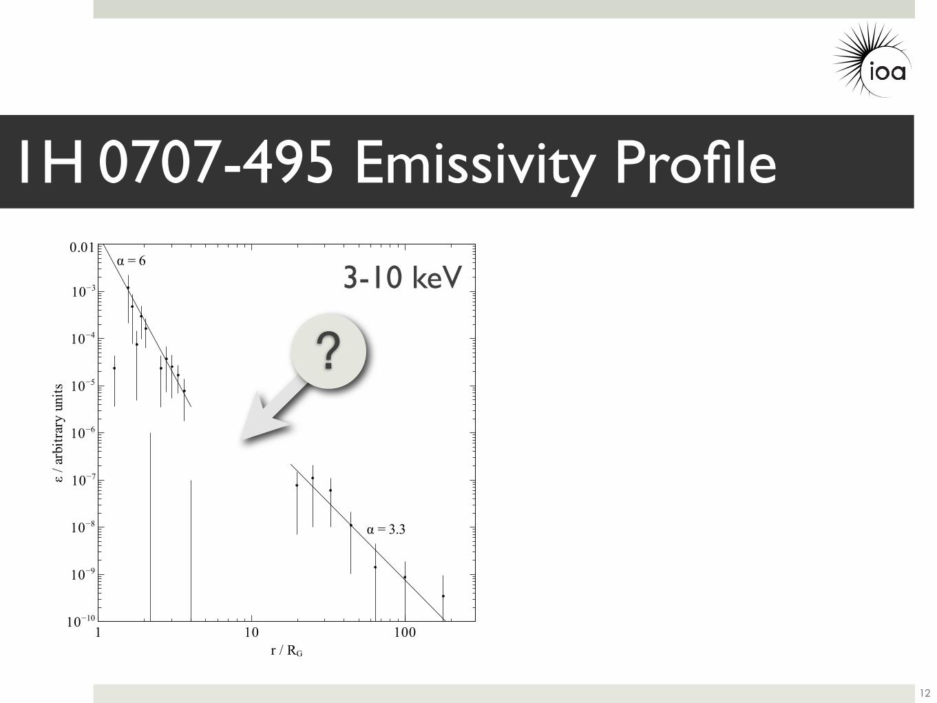
! = 3.3
! = 6
" /
arbi
trar
y u
nits
10#10
10#9
10#8
10#7
10#6
10#5
10#4
10#3
0.01
r / RG
1 10 100
1H 0707-495 Emissivity Profile
12
3-10 keV
?
! = 3.3
! = 6
" /
arbi
trar
y u
nits
10#10
10#9
10#8
10#7
10#6
10#5
10#4
10#3
0.01
r / RG
1 10 100
! = 0
! = 7.8
" /
arbi
trar
y u
nits
10#12
10#9
10#6
10#3
r / RG
1 10 100
1H 0707-495 Emissivity Profile
12
3-10 keV 3-5 keV
?
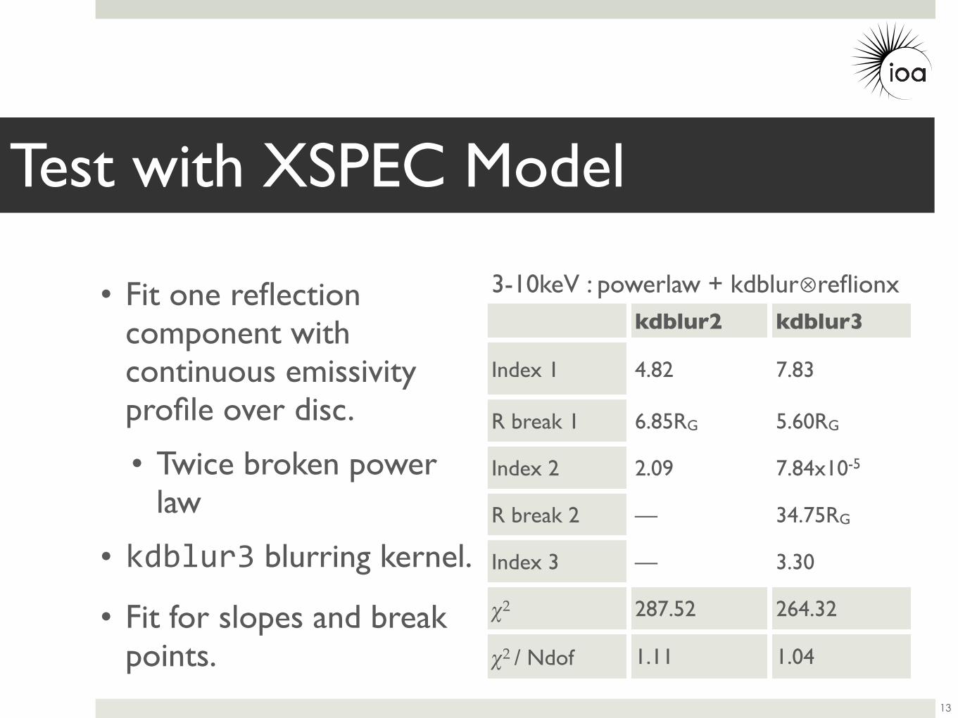
• Fit one reflection component with continuous emissivity profile over disc.
• Twice broken power law
• kdblur3 blurring kernel.
• Fit for slopes and break points.
Test with XSPEC Model
13
kdblur2 kdblur3
Index 1 4.82 7.83
R break 1 6.85RG 5.60RG
Index 2 2.09 7.84x10⁻⁵
R break 2 — 34.75RG
Index 3 — 3.30
χ2 287.52 264.32
χ2 / Ndof 1.11 1.04
3-10keV : powerlaw + kdblur⊗reflionx
10 3
0.01
norm
aliz
ed c
ount
s s
keV
105
0.8
1
1.2
ratio
Energy (keV)
10 3
0.01
norm
aliz
ed c
ount
s s
keV
105
0.8
1
1.2
1.4ra
tio
Energy (keV)
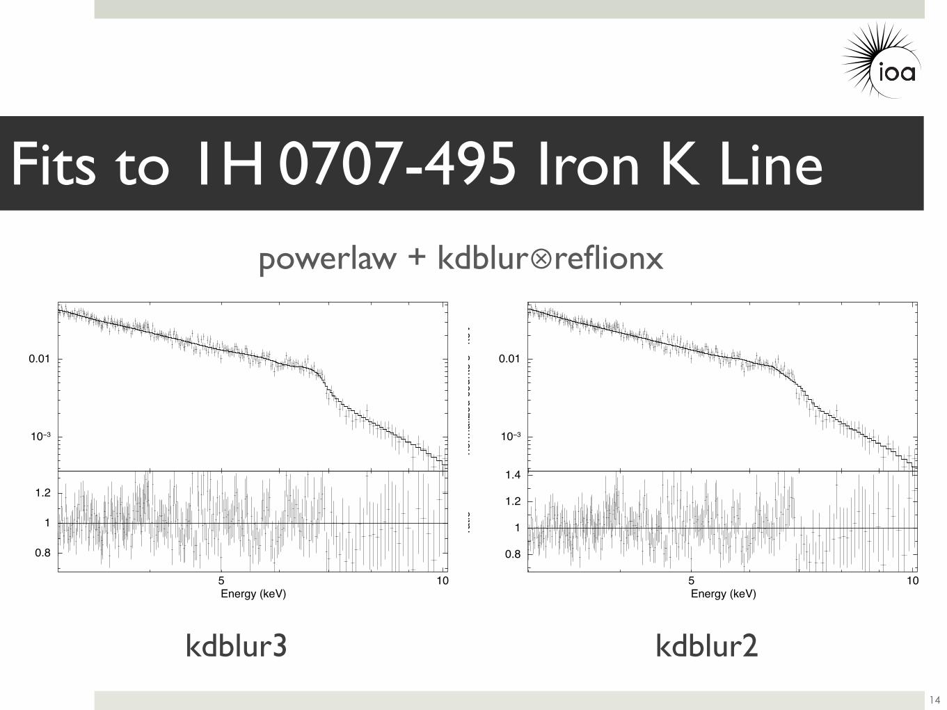
Fits to 1H 0707-495 Iron K Line
14
kdblur3 kdblur2
powerlaw + kdblur⊗reflionx
1e-10
1e-09
1e-08
1e-07
1e-06
1e-05
0.0001
0.001
0.01
0.1
1
1 10 100 1000
/ ar
bitra
ry u
nits
r / rg
kdblur3kdblur2
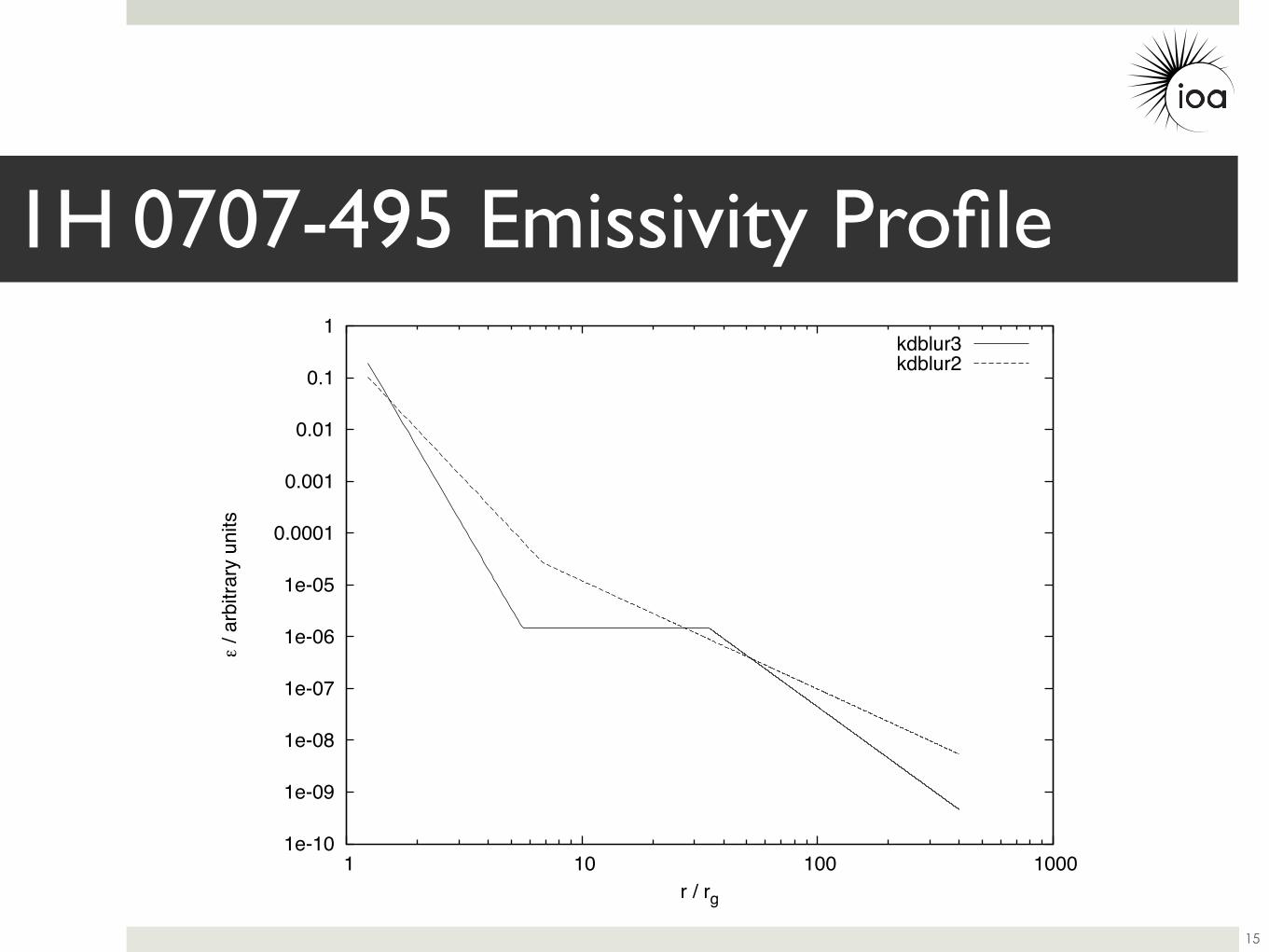
1H 0707-495 Emissivity Profile
15
16
0.6
0.7
0.8
0.9
1
1.1
1 10 100 1000
F( <
r )
/ F(
<40
0rg
)
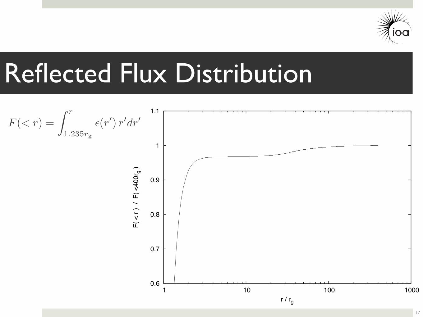
r / rg
F (< r) =
r
1.235rg
(r) rdr
17
Reflected Flux Distribution
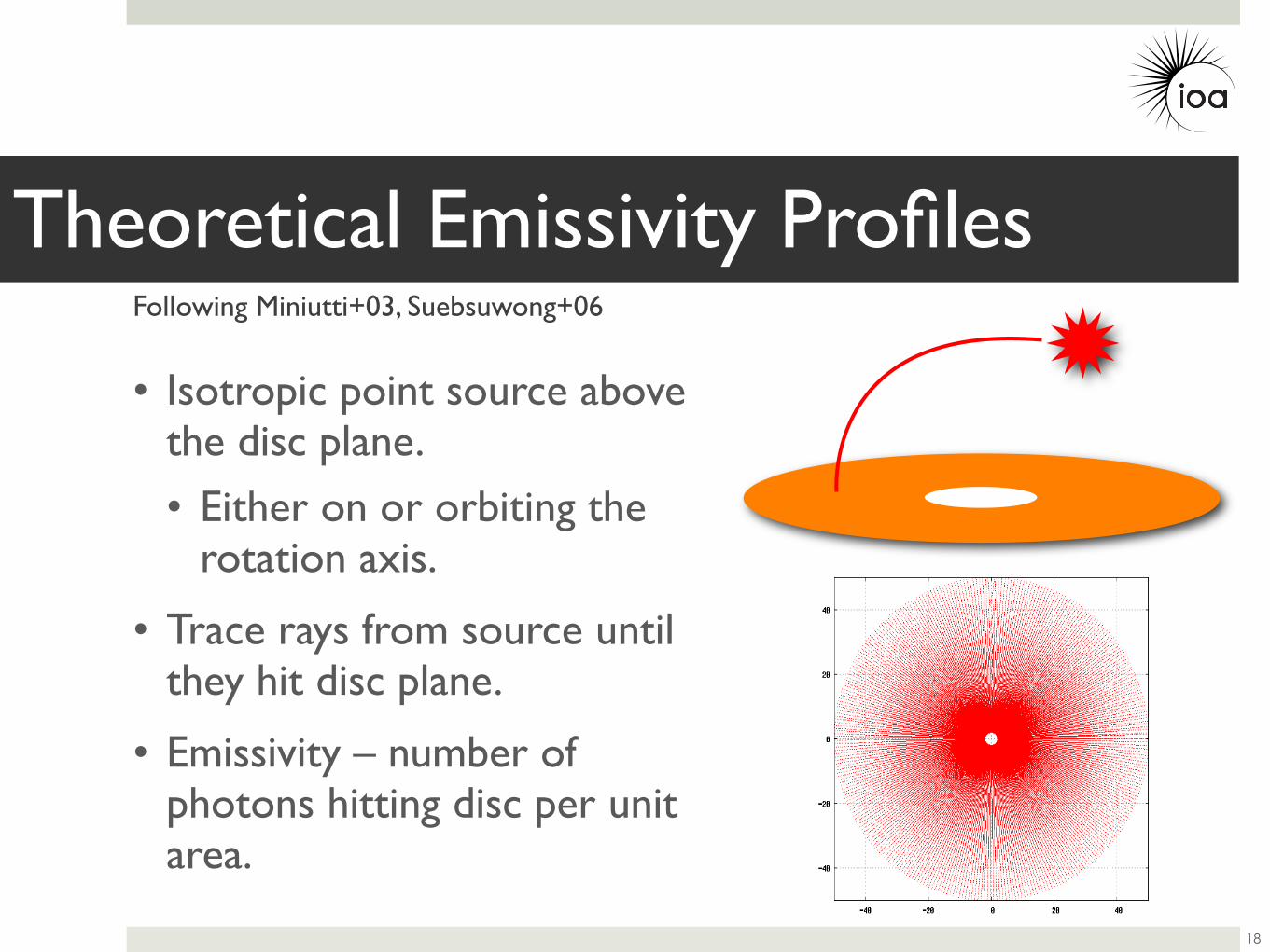
• Isotropic point source above the disc plane.
• Either on or orbiting the rotation axis.
• Trace rays from source until they hit disc plane.
• Emissivity – number of photons hitting disc per unit area.
18
Theoretical Emissivity ProfilesFollowing Miniutti+03, Suebsuwong+06
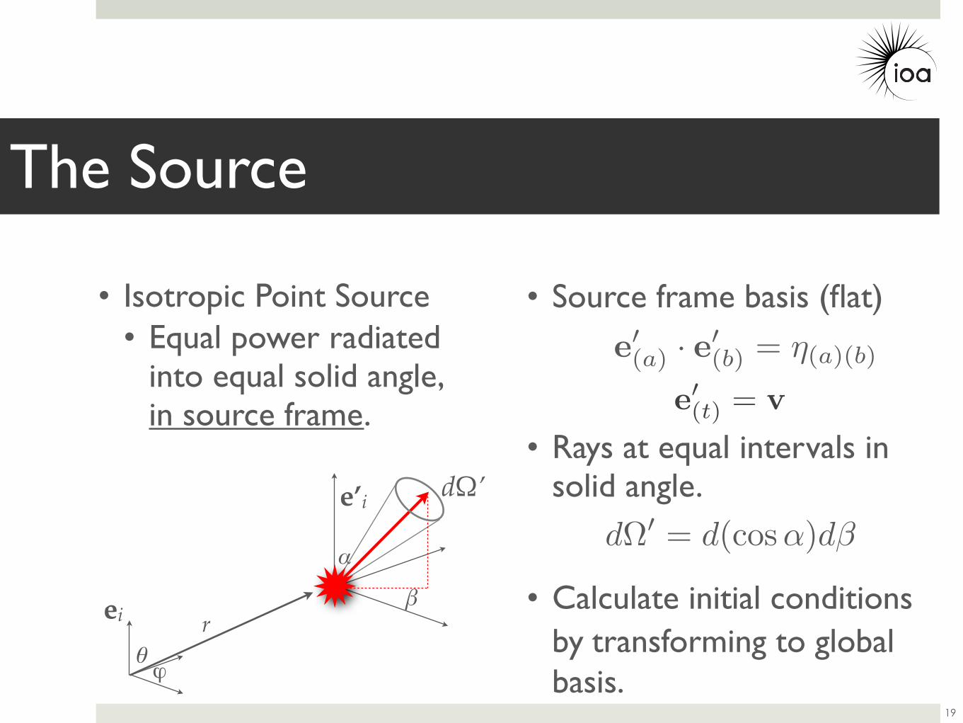
e(t) = v
The Source
19
e(a) · e
(b) = η(a)(b)
• Source frame basis (flat)
• Rays at equal intervals in solid angle.
• Calculate initial conditions by transforming to global basis.
• Isotropic Point Source• Equal power radiated
into equal solid angle, in source frame.
dΩ = d(cos α)dβα
βei
e’i
θϕ
r
dΩ’
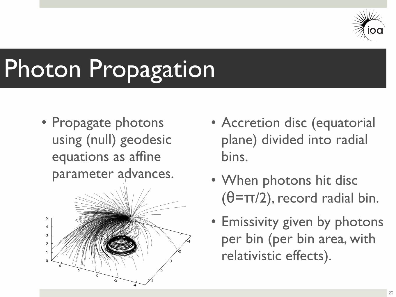
• Propagate photons using (null) geodesic equations as affine parameter advances.
Photon Propagation
20
• Accretion disc (equatorial plane) divided into radial bins.
• When photons hit disc (θ=π/2), record radial bin.
• Emissivity given by photons per bin (per bin area, with relativistic effects).
-4-2
0 2
4
-4
-2
0
2
4
0
1
2
3
4
5
1e-06
1e-05
0.0001
0.001
0.01
0.1
1 10 100r
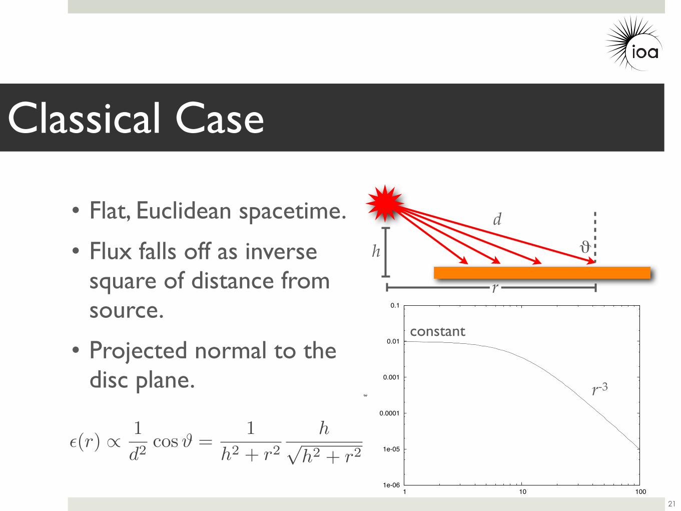
• Flat, Euclidean spacetime.
• Flux falls off as inverse square of distance from source.
• Projected normal to the disc plane.
Classical Case
21
(r) ∝ 1
d2cosϑ =
1
h2 + r2h√
h2 + r2
d
h
r
r-3
constant
ϑ
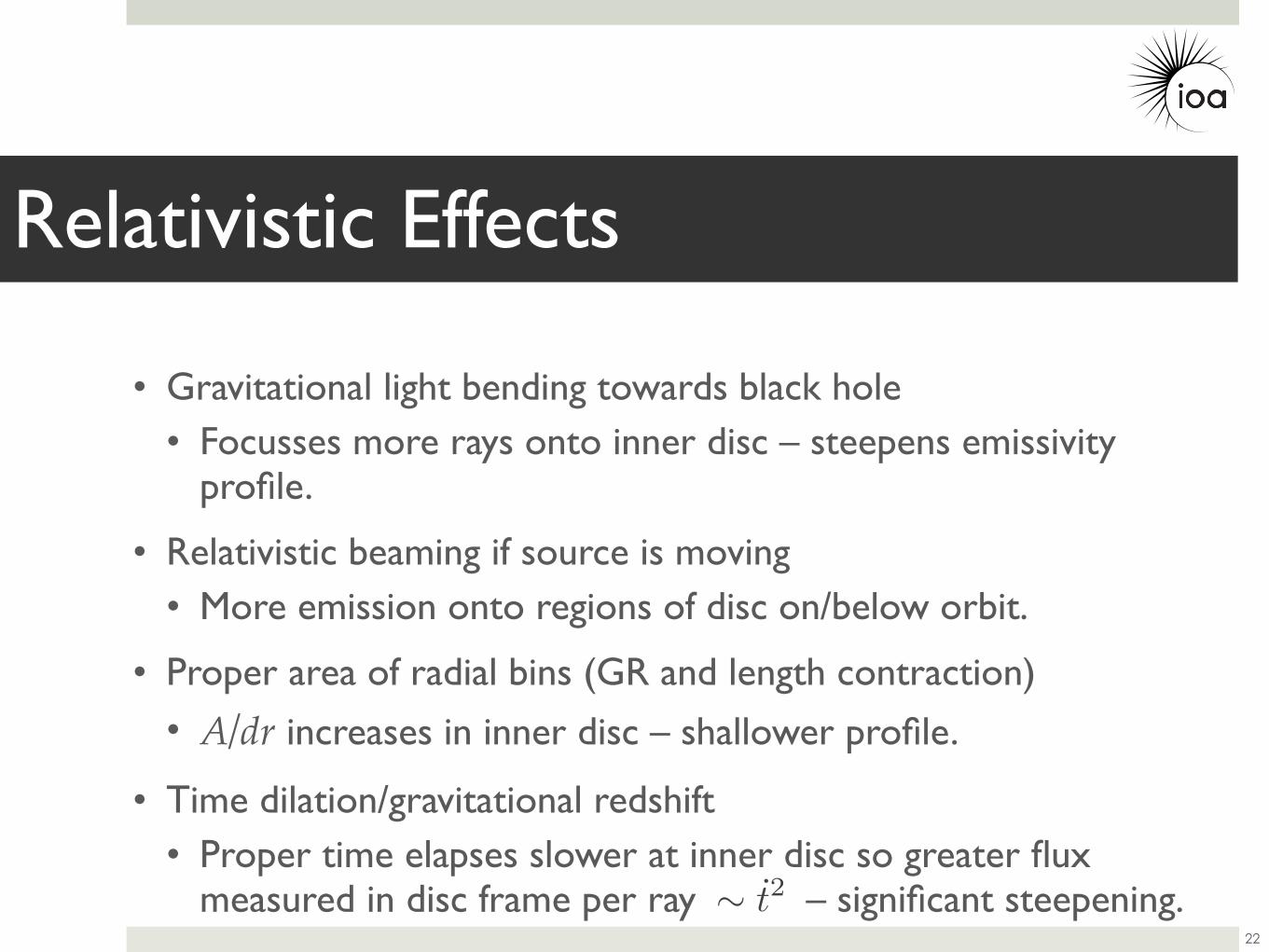
• Gravitational light bending towards black hole• Focusses more rays onto inner disc – steepens emissivity
profile.
• Relativistic beaming if source is moving• More emission onto regions of disc on/below orbit.
• Proper area of radial bins (GR and length contraction)
• A/dr increases in inner disc – shallower profile.
• Time dilation/gravitational redshift• Proper time elapses slower at inner disc so greater flux
measured in disc frame per ray – significant steepening.
Relativistic Effects
22
∼ t2
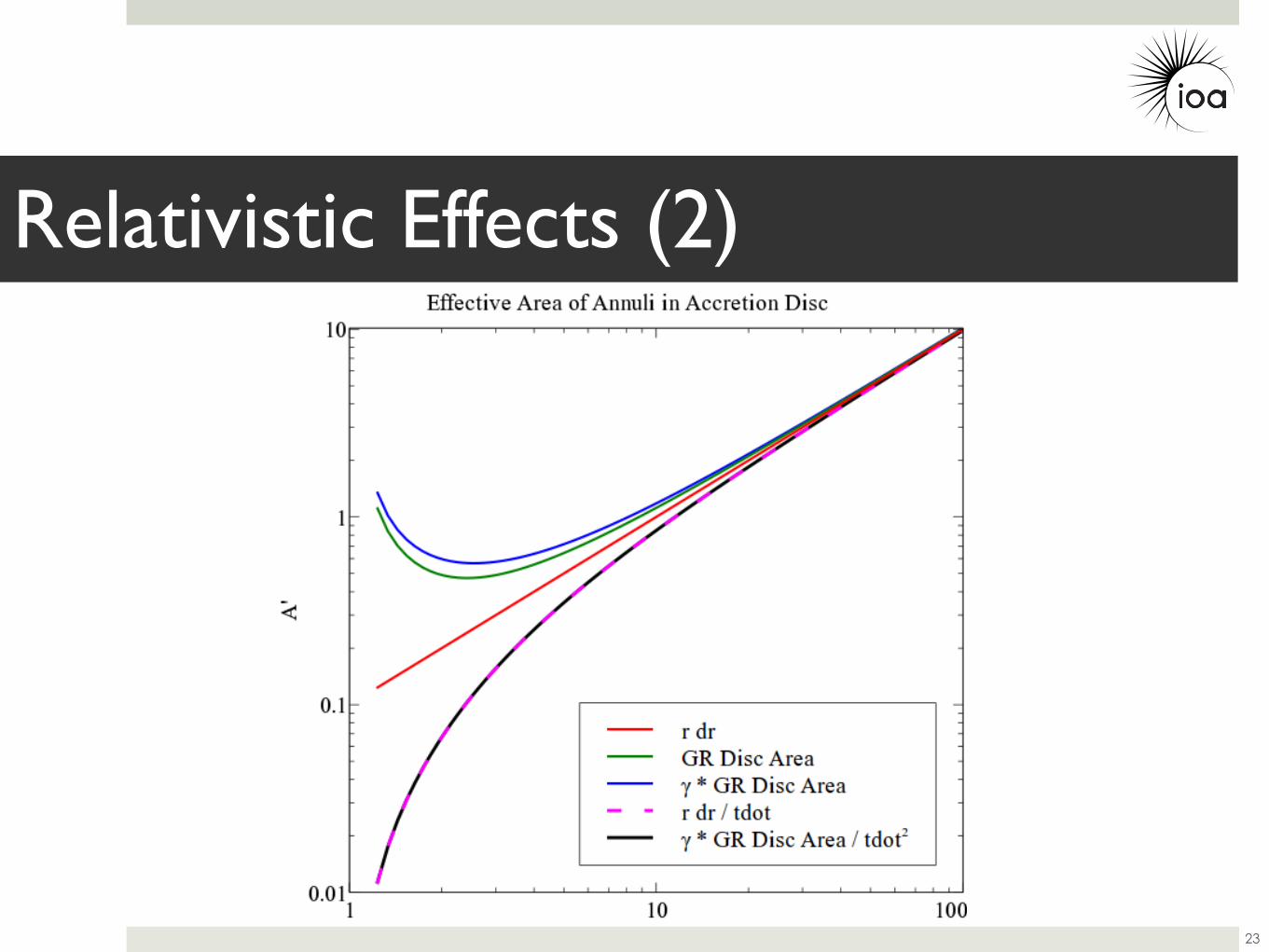
Relativistic Effects (2)
23
0.01
0.1
1
10
100
1000
10000
100000
1e+06
1 10 100 1000
/ ar
bitra
ry u
nits
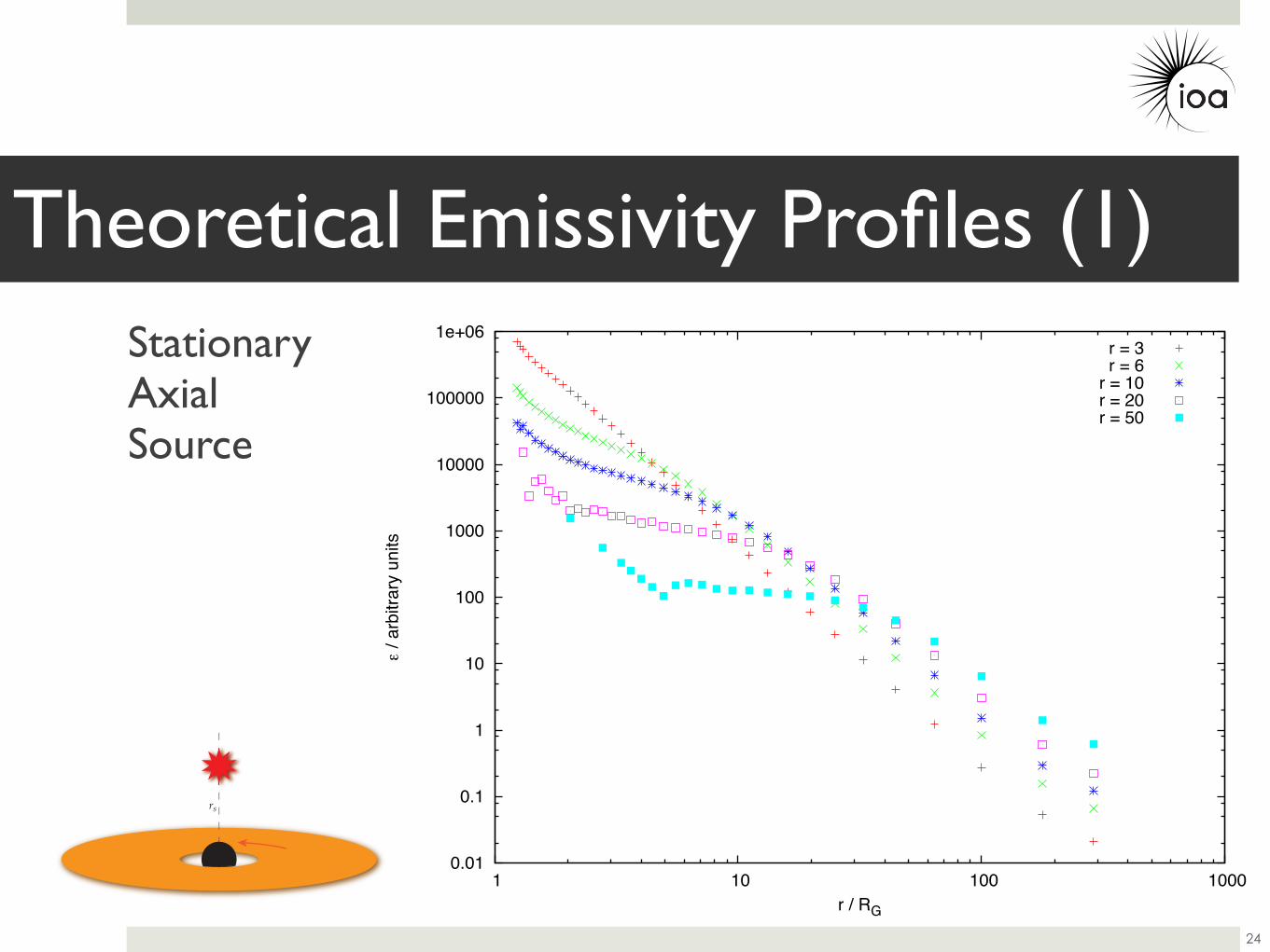
r / RG
r = 3r = 6
r = 10r = 20r = 50
rs
Theoretical Emissivity Profiles (1)
24
StationaryAxialSource
0.01
0.1
1
10
100
1000
10000
100000
1e+06
1 10 100 1000
/ ar
bitra
ry u
nits
r / RG
r = 3r = 6
r = 10r = 20r = 50
rs
Theoretical Emissivity Profiles (1)
24
StationaryAxialSource
α~7
α~3.3
0.01
0.1
1
10
100
1000
10000
100000
1e+06
1 10 100 1000
/ ar
bitra
ry u
nits
r / RG
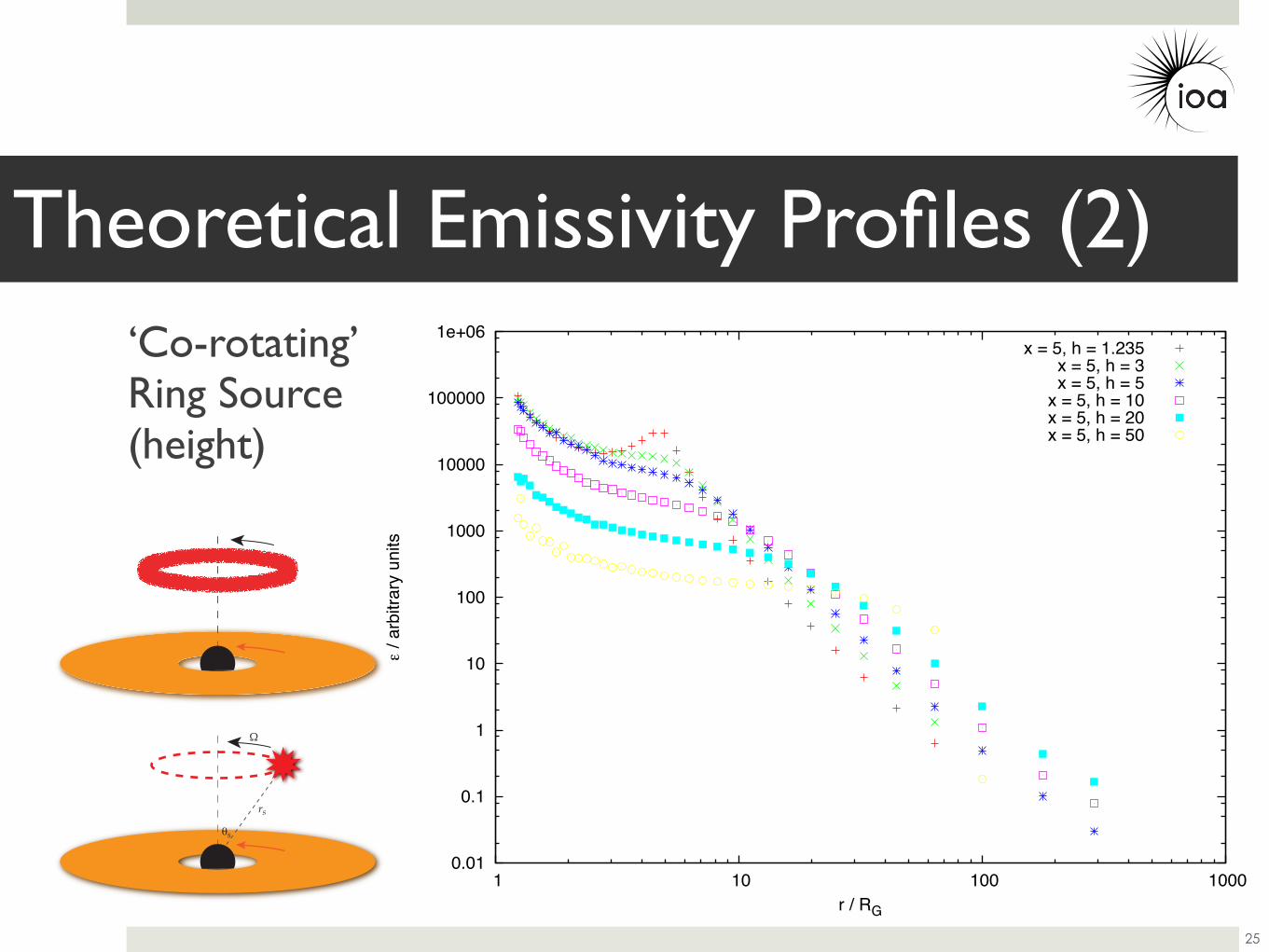
x = 5, h = 1.235x = 5, h = 3x = 5, h = 5
x = 5, h = 10x = 5, h = 20x = 5, h = 50
!"
"
Theoretical Emissivity Profiles (2)
25
‘Co-rotating’Ring Source(height)

0.01
0.1
1
10
100
1000
10000
100000
1e+06
1 10 100 1000
/ ar
bitra
ry u
nits
r / RG
x = 1.235, h = 5x = 3, h = 5x = 5, h = 5
x = 10, h = 5
Theoretical Emissivity Profiles (3)
26
!"
"
‘Co-rotating’Ring Source(radius)
0.01
0.1
1
10
100
1000
10000
1 10 100 1000
/ ar
bitra
ry u
nits
r / RG
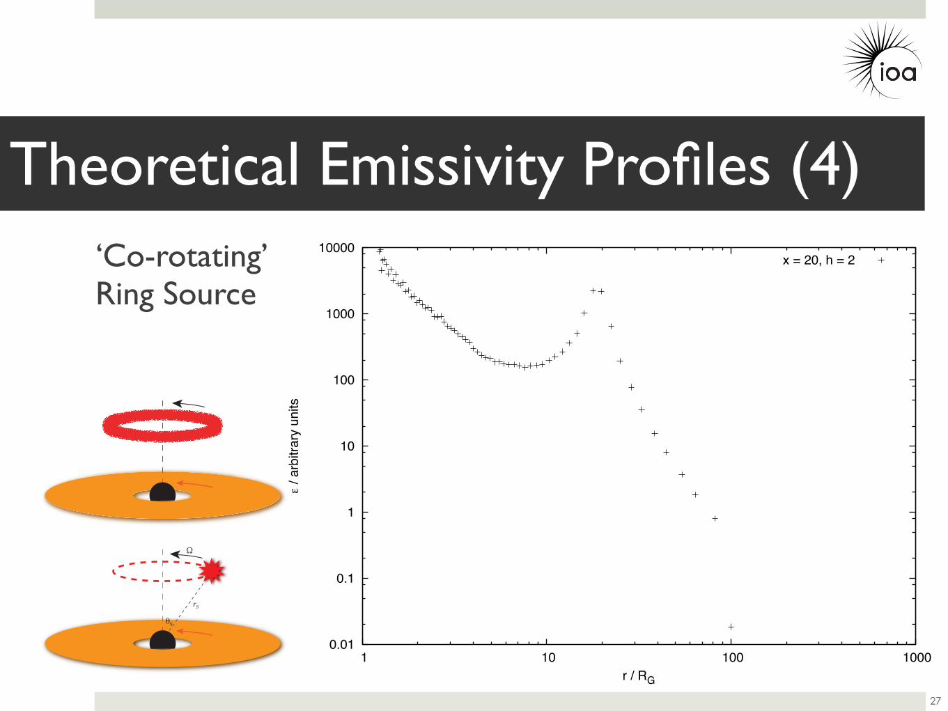
x = 20, h = 2
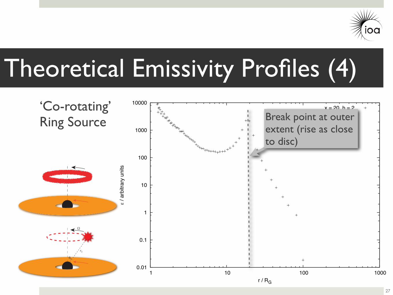
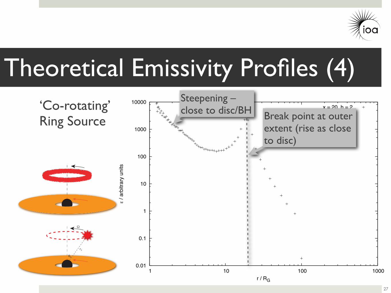
Theoretical Emissivity Profiles (4)
27
!"
"
‘Co-rotating’Ring Source
0.01
0.1
1
10
100
1000
10000
1 10 100 1000
/ ar
bitra
ry u
nits
r / RG
x = 20, h = 2
Theoretical Emissivity Profiles (4)
27
!"
"
‘Co-rotating’Ring Source Break point at outer
extent (rise as close to disc)
0.01
0.1
1
10
100
1000
10000
1 10 100 1000
/ ar
bitra
ry u
nits
r / RG
x = 20, h = 2
Theoretical Emissivity Profiles (4)
27
!"
"
‘Co-rotating’Ring Source Break point at outer
extent (rise as close to disc)
Steepening – close to disc/BH
• Simulations of point sources explain basic form of emissivity profile.
• Steep inner part due to time dilation/gravitational redshift.
• Flattening in middle region (h » r).• Constant index slightly steeper than classical (3).
Theoretical Results
28
• Outer break radius (flat to constant index outer disc) lies approximately below the source.
• Greater steepening at inner disc for sources closer to the black hole.
• Either source radius or height above disc.
Theoretical Results (2)
29

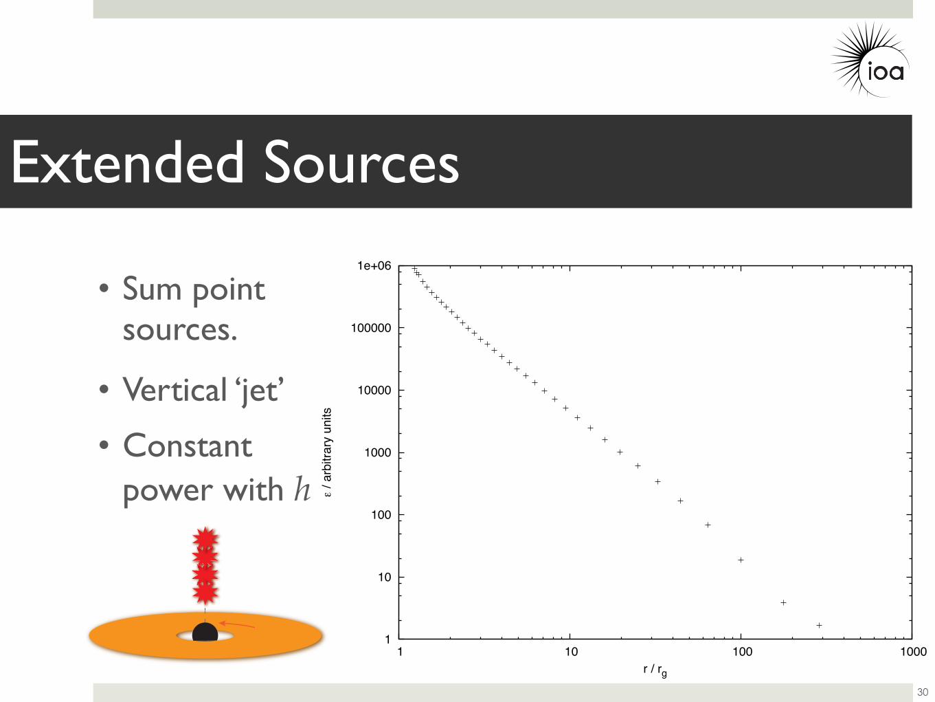
Extended Sources
30
• Sum point sources.
1
10
100
1000
10000
100000
1e+06
1 10 100 1000
/ ar
bitra
ry u
nits
r / rg
• Vertical ‘jet’
• Constant power with h
Extended Sources
30
• Sum point sources.
0.01
0.1
1
10
100
1000
10000
100000
1e+06
1 10 100 1000
/ ar
bitra
ry u
nits
r / rg
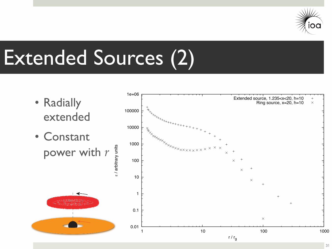
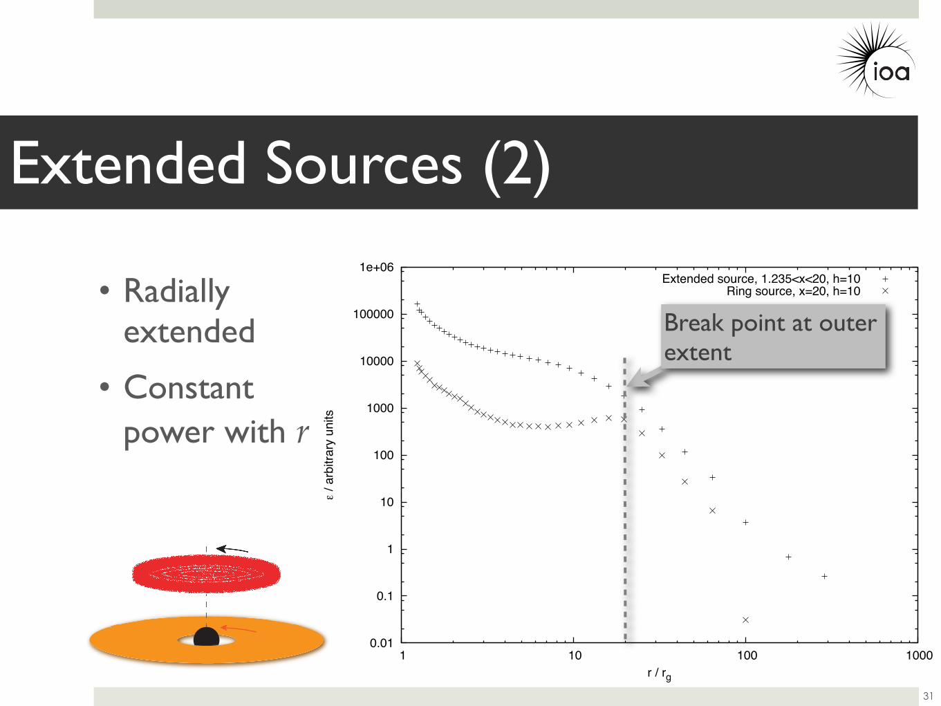
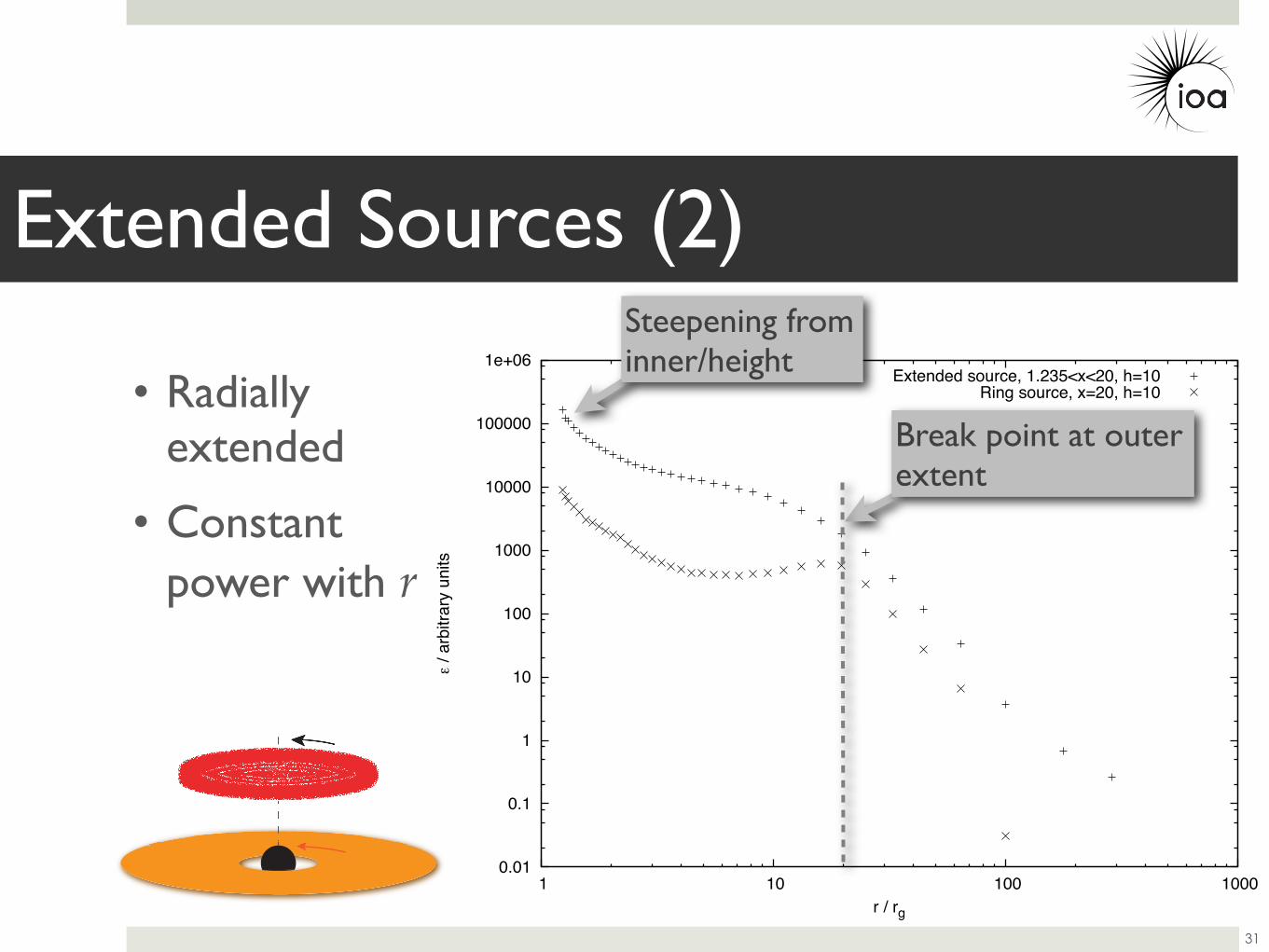
Extended source, 1.235<x<20, h=10Ring source, x=20, h=10• Radially
extended
• Constant power with r
Extended Sources (2)
31
0.01
0.1
1
10
100
1000
10000
100000
1e+06
1 10 100 1000
/ ar
bitra
ry u
nits
r / rg
Extended source, 1.235<x<20, h=10Ring source, x=20, h=10• Radially
extended
• Constant power with r
Extended Sources (2)
31
Break point at outer extent
0.01
0.1
1
10
100
1000
10000
100000
1e+06
1 10 100 1000
/ ar
bitra
ry u
nits
r / rg
Extended source, 1.235<x<20, h=10Ring source, x=20, h=10• Radially
extended
• Constant power with r
Extended Sources (2)
31
Break point at outer extent
Steepening from inner/height
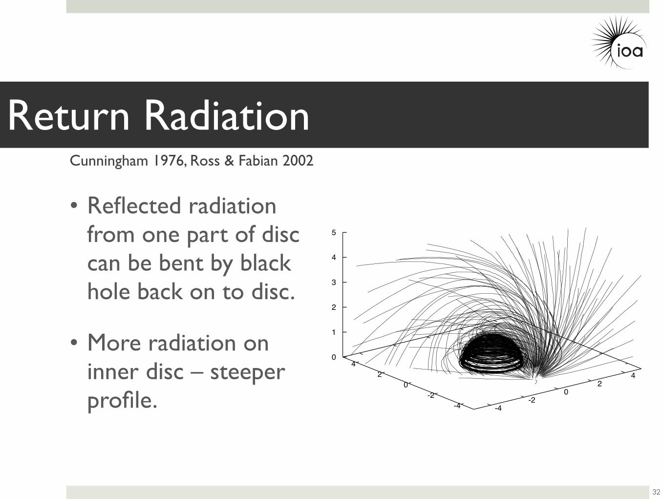
-4-2
0 2
4
-4-2
0 2
4 0
1
2
3
4
5
• Reflected radiation from one part of disc can be bent by black hole back on to disc.
• More radiation on inner disc – steeper profile.
Return Radiation
32
Cunningham 1976, Ross & Fabian 2002
• Determined emissivity profile of 1H 0707-495 without a priori assumption of its form.• Twice broken power law.• Steep (α~7.8) in inner disc, flat 5.6–34.8RG, α~3.3 over outer
disc.
• Consistent with XSPEC fit to reflection spectrum using one continuous emissivity profile.
• Form of emissivity profile agrees with theoretical prediction.• Understand form in terms of physics (relativistic effects).
• Can constrain properties of hard X-ray source...
Conclusions
33