Embed Size (px)
Citation preview
THE ELLIPSE CHUCK Introduction. The Ellipse Chuck as made by Holtzapffel & Co., comprises an Eccentric Chuck without a leadscrew. The movement of the slide is controlled by two straight steel pallets which embrace a bronze Cam-ring of about 4” outer diameter. The Cam-ring has a long backplate which is mounted on the front of the headstock and the ring may be adjusted horizontally, from concentricity with the mandrel to any eccentricity up to about 1½ inches to the left on the mandrel. The eccentricity of the Cam-ring is imparted to the pallets which cause the slide to move outwards to the chosen eccentricity and then back to concentricity twice during each rotation of the mandrel. Fitting and Adjusting should be carried out carefully to ensure minimum vibration and wear of the Chuck. First check that the two indentations on either side of the headstock are clean; then fit the cam-ring in the neutral position (i.e. with the scale set to zero). Take care not to distort the ring by over-tightening the thumb-screws. Set the pallets parallel and at 90º to the chuck slide and adjust them carefully so they bear on the ring all the way around without either play or tightness. The surface of the ring and the slide of the Chuck should be well-lubricated at all times. The chuck should never be run in the central (or neutral) position as this can cause a groove to be worn at the centre of each pallet. Rough-turn the workpiece to a cylinder, slightly larger than the desired major axis; preferably with the work-holding chuck mounted directly onto the mandrel to minimise overhang. If the piece is to be bored out elliptically, rough-bore it circularly slightly smaller than the desired minor axis. Mount the workpiece on the Ellipse Chuck with the cam ring removed (to avoid wear) and fix the chuck in its central position with the steady pin and turn the face, leaving a tiny pip for a datum so that the cutting tool may be adjusted exactly to centre and thereafter, to enable the accurate setting of distances from centre (e.g. to bore-out an ellipse with a minor axis of one inch, the cutter must be advanced by half-an-inch to left of the centre position). If the centre pip is to be cut away this datum position may be preserved either by fixing a fluting stop to the right of the tool-slide or, by positioning the slide-rest so that the central position may be returned to easily at any time. This may be done by setting the micrometer on the slide-rest leadscrew set to zero and the crank-handle hanging down. If the micrometer on your slide-rest cannot be adjusted it is quite easy to loosen the holding bolt of the slide-rest base and slide it transversely, tapping it into the central position using a soft-head mallet, so as to be able at any time to place cuts at a pre-determined radius from the zero or central position. The slide-rest must be locked to its cradle to preserve this position but, if the project necessitates unlocking the slide-r
Fig. 1.
est, and
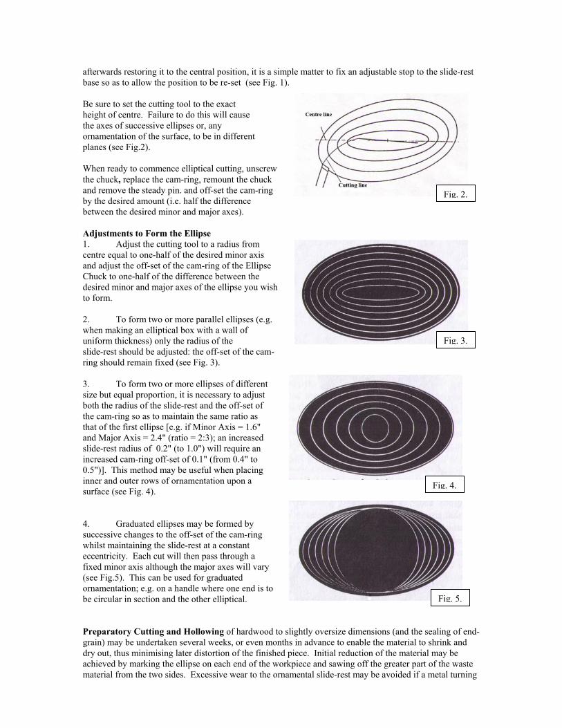
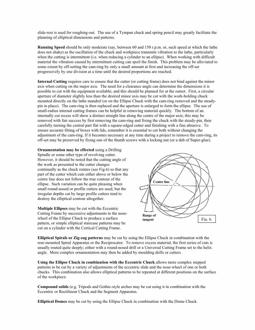
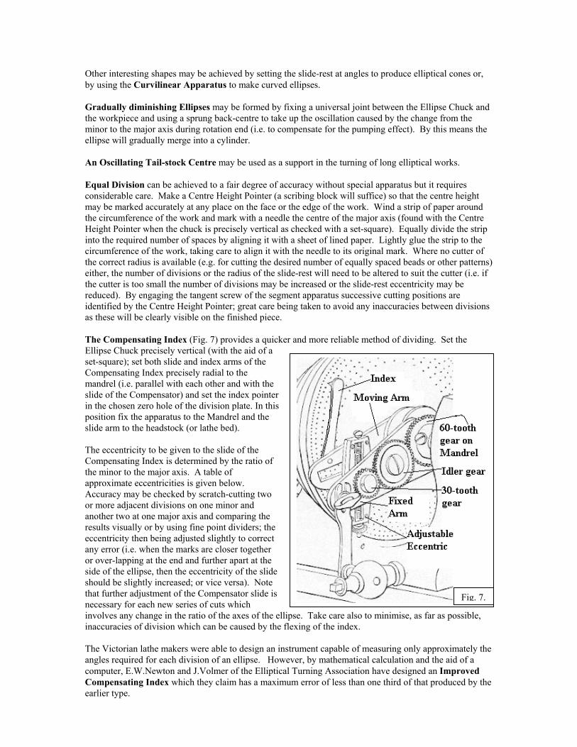
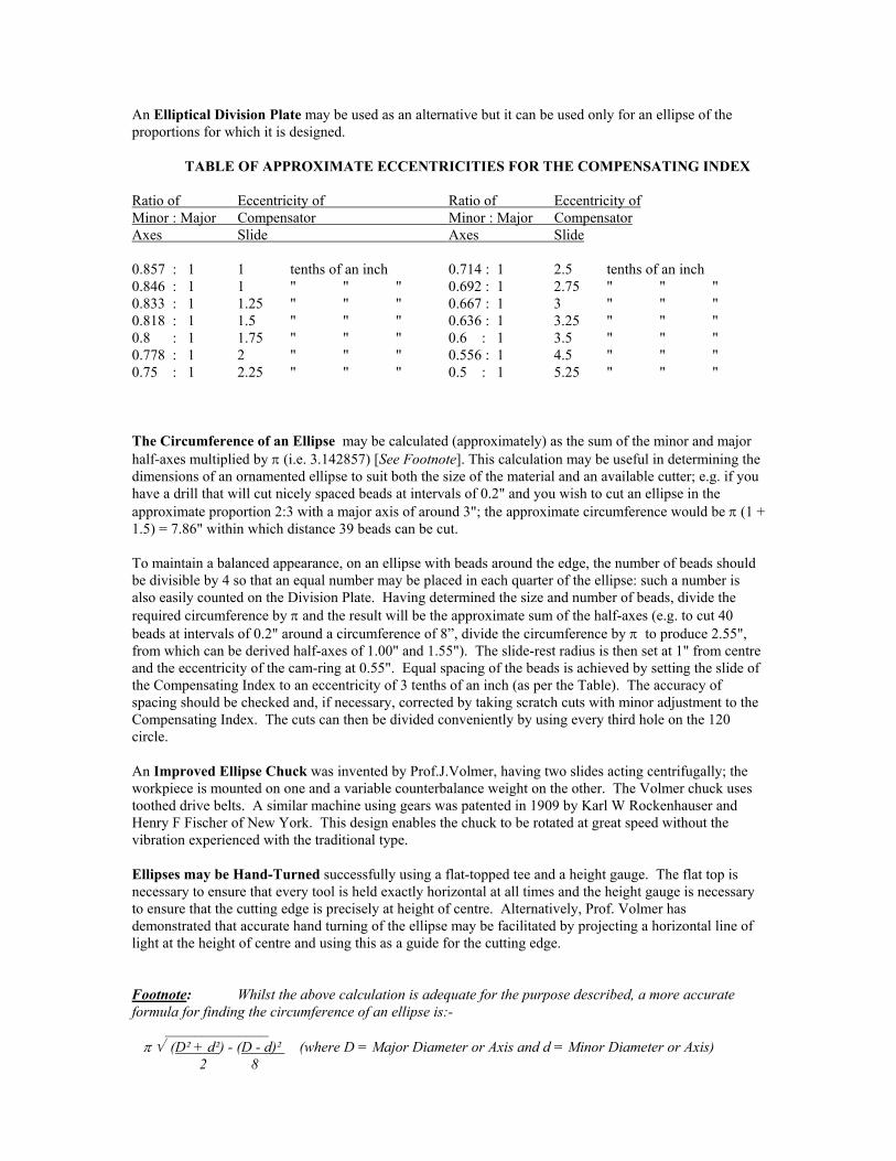
afterwards restoring it to the central position, it is a simple matter to fix an adjustable stop to the slide-rest base so as to allow the position to be re-set (see Fig. 1). Be sure to set the cutting tool to the exact height of centre. Failure to do this will cause the axes of successive ellipses or, any ornamentation of the surface, to be in different planes (see Fig.2). When ready to commence elliptical cutting, unscrew the chuck, replace the cam-ring, remount the chuck and remove the steady pin. and off-set the cam-ring by the desired amount (i.e. half the difference between the desired minor and major axes). Adjustments to Form the Ellipse 1. Adjust the cutting tool to a radius from centre equal to one-half of the desired minor axis and adjust the off-set of the cam-ring of the Ellipse Chuck to one-half of the difference between the desired minor and major axes of the ellipse you wish to form. 2. To form two or more parallel ellipses (e.g. when making an elliptical box with a wall of uniform thickness) only the radius of the slide-rest should be adjusted: the off-set of the cam-ring should remain fixed (see Fig. 3). 3. To form two or more ellipses of different size but equal proportion, it is necessary to adjust both the radius of the slide-rest and the off-set of the cam-ring so as to maintain the same ratio as that of the first ellipse [e.g. if Minor Axis = 1.6" and Major Axis = 2.4" (ratio = 2:3); an increased slide-rest radius of 0.2" (to 1.0") will require an increased cam-ring off-set of 0.1" (from 0.4" to 0.5")]. This method may be useful when placing inner and outer rows of ornamentation upon a surface (see Fig. 4). 4. Graduated ellipses may be formed by successive changes to the off-set of the cam-ring whilst maintaining the slide-rest at a constant eccentricity. Each cut will then pass through a fixed minor axis although the major axes will vary (see Fig.5). This can be used for graduated ornamentation; e.g. on a handle where one end is to be circular in section and the other elliptical. Preparatory Cutting and Hollowing of hardwood to slightly oversize dimensions (and the sealgrain) may be undertaken several weeks, or even months in advance to enable the material to shrdry out, thus minimising later distortion of the finished piece. Initial reduction of the material machieved by marking the ellipse on each end of the workpiece and sawing off the greater part of material from the two sides. Excessive wear to the ornamental slide-rest may be avoided if a me
Fig. 3.
Fig. 2.
Fig. 5.
Fig. 4.
ing of end-ink and ay be the waste tal turning
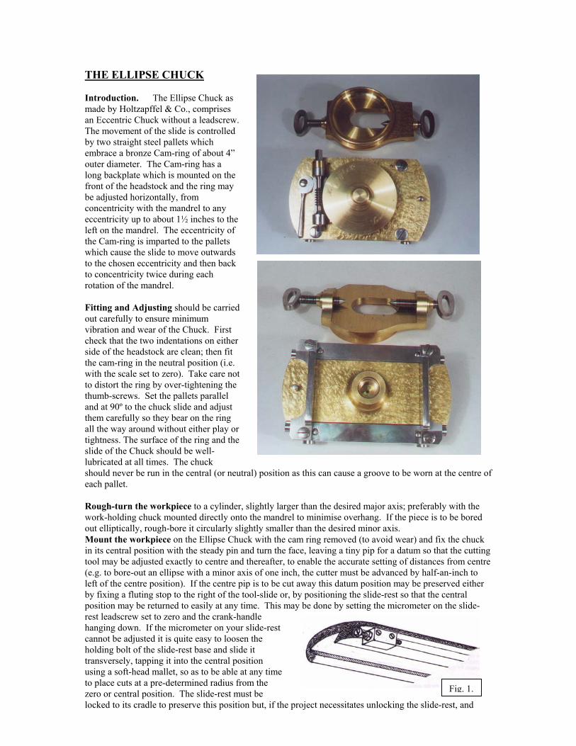
slide-rest is used for roughing-out. The use of a Tympan chuck and spring pencil may greatly facilitate the planning of elliptical dimensions and patterns. Running Speed should be only moderate (say, between 60 and 150 r.p.m. or, such speed at which the lathe does not shake) as the oscillation of the chuck and workpiece transmits vibration to the lathe, particularly when the cutting is intermittent (i.e. when reducing a cylinder to an ellipse). When working with difficult material the vibration caused by intermittent cutting can spoil the finish. This problem may be alleviated to some extent by off-setting the cam-ring by only a small amount at first and increasing the off-set progressively by one division at a time until the desired proportions are reached. Internal Cutting requires care to ensure that the cutter (or cutting frame) does not bind against the minor axis when cutting on the major axis. The need for a clearance angle can determine the dimensions it is possible to cut with the equipment available; and this should be planned for at the outset. First, a circular aperture of diameter slightly less than the desired minor axis may be cut with the work-holding chuck mounted directly on the lathe mandrel (or on the Ellipse Chuck with the cam-ring removed and the steady-pin in place). The cam-ring is then replaced and the aperture is enlarged to form the ellipse. The use of small-radius internal cutting frames can be helpful in removing material quickly. The bottom of an internally cut recess will show a distinct straight line along the centre of the major axis; this may be removed with fair success by first removing the cam-ring and fixing the chuck with the steady-pin, then carefully turning the central part flat with a square-edged cutter and finishing with a fine abrasive. To ensure accurate fitting of boxes with lids, remember it is essential to cut both without changing the adjustment of the cam-ring. If it becomes necessary at any time during a project to remove the cam-ring, its off-set may be preserved by fixing one of the thumb screws with a locking nut (or a dab of Super-glue). Ornamentation may be effected using a Drilling Spindle or some other type of revolving cutter. However, it should be noted that the cutting angle of the work as presented to the cutter changes continually as the chuck rotates (see Fig.6) so that any part of the cutter which cuts either above or below the centre line does not follow the true contour of the ellipse. Such variation can be quite pleasing when small round-nosed or profile cutters are used, but the irregular depths cut by large profile cutters tend to destroy the elliptical contour altogether. Multiple Ellipses may be cut with the Eccentric Cutting Frame by successive adjustments to the nose-wheel of the Ellipse Chuck to produce a surface pattern, or simple elliptical staircase patterns may be cut on a cylinder with the Certical Cutting Frame. Elliptical Spirals or Zig-zag patterns may be cut by usinrear-mounted Spiral Apparatus or the Reciprocator. To reusually routed quite deeply; either with a round-nosed driangle. More complex ornamentation may then be added b Using the Ellipse Chuck in combination with the Eccenpatterns to be cut by a variety of adjustments of the eccenchucks. This combination also allows elliptical patterns tof the workpiece. Compound solids (e.g. Tripods and Gothic-style arches mEccentric or Rectilinear Chuck and the Segment Apparatu Elliptical Domes may be cut by using the Ellipse Chuck
g the Ellipse Chuck in combination wmove excess material, the first series oll or a Universal Cutting Frame set to thy moulding drills or cutters.
tric Chuck allows more complex steptric slide and the nose-wheel of one or o be repeated at different positions on t
ay be cut using it in combination withs.
in combination with the Dome Chuck.
Fig. 6.
ith the f cuts is e helix
ped both he surface
the
Other interesting shapes may be achieved by setting the slide-rest at angles to produce elliptical cones or, by using the Curvilinear Apparatus to make curved ellipses. Gradually diminishing Ellipses may be formed by fixing a universal joint between the Ellipse Chuck and the workpiece and using a sprung back-centre to take up the oscillation caused by the change from the minor to the major axis during rotation end (i.e. to compensate for the pumping effect). By this means the ellipse will gradually merge into a cylinder. An Oscillating Tail-stock Centre may be used as a support in the turning of long elliptical works. Equal Division can be achieved to a fair degree of accuracy without special apparatus but it requires considerable care. Make a Centre Height Pointer (a scribing block will suffice) so that the centre height may be marked accurately at any place on the face or the edge of the work. Wind a strip of paper around the circumference of the work and mark with a needle the centre of the major axis (found with the Centre Height Pointer when the chuck is precisely vertical as checked with a set-square). Equally divide the strip into the required number of spaces by aligning it with a sheet of lined paper. Lightly glue the strip to the circumference of the work, taking care to align it with the needle to its original mark. Where no cutter of the correct radius is available (e.g. for cutting the desired number of equally spaced beads or other patterns) either, the number of divisions or the radius of the slide-rest will need to be altered to suit the cutter (i.e. if the cutter is too small the number of divisions may be increased or the slide-rest eccentricity may be reduced). By engaging the tangent screw of the segment apparatus successive cutting positions are identified by the Centre Height Pointer; great care being taken to avoid any inaccuracies between divisions as these will be clearly visible on the finished piece. The Compensating Index (Fig. 7) provides a quicker and more reliable method of dividing. Set the Ellipse Chuck precisely vertical (with the aid of a set-square); set both slide and index arms of the Compensating Index precisely radial to the mandrel (i.e. parallel with each other and with the slide of the Compensator) and set the index pointer in the chosen zero hole of the division plate. In this position fix the apparatus to the Mandrel and the slide arm to the headstock (or lathe bed). The eccentricity to be given to the slide of the Compensating Index is determined by the ratio of the minor to the major axis. A table of approximate eccentricities is given below. Accuracy may be checked by scratch-cutting two or more adjacent divisions on one minor and another two at one major axis and comparing the results visually or by using fine point dividers; the eccentricity then being adjusted slightly to correct any error (i.e. when the marks are closer together or over-lapping at the end and further apart at the side of the ellipse, then the eccentricity of the slide should be slightly increased; or vice versa). Note that further adjustment of the Compensator slide is necessary for each new series of cuts which involves any change in the ratio of the axes of the ellipse. Take care also to minimise, as far as poinaccuracies of division which can be caused by the flexing of the index. The Victorian lathe makers were able to design an instrument capable of measuring only approximangles required for each division of an ellipse. However, by mathematical calculation and the aidcomputer, E.W.Newton and J.Volmer of the Elliptical Turning Association have designed an ImpCompensating Index which they claim has a maximum error of less than one third of that producearlier type.
Fig. 7.
ssible,
ately the of a roved ed by the
An Elliptical Division Plate may be used as an alternative but it can be used only for an ellipse of the proportions for which it is designed. TABLE OF APPROXIMATE ECCENTRICITIES FOR THE COMPENSATING INDEX Ratio of Eccentricity of Ratio of Eccentricity of Minor : Major Compensator Minor : Major Compensator Axes Slide Axes Slide 0.857 : 1 1 tenths of an inch 0.714 : 1 2.5 tenths of an inch 0.846 : 1 1 " " " 0.692 : 1 2.75 " " " 0.833 : 1 1.25 " " " 0.667 : 1 3 " " " 0.818 : 1 1.5 " " " 0.636 : 1 3.25 " " " 0.8 : 1 1.75 " " " 0.6 : 1 3.5 " " " 0.778 : 1 2 " " " 0.556 : 1 4.5 " " " 0.75 : 1 2.25 " " " 0.5 : 1 5.25 " " " The Circumference of an Ellipse may be calculated (approximately) as the sum of the minor and major half-axes multiplied by π (i.e. 3.142857) [See Footnote]. This calculation may be useful in determining the dimensions of an ornamented ellipse to suit both the size of the material and an available cutter; e.g. if you have a drill that will cut nicely spaced beads at intervals of 0.2" and you wish to cut an ellipse in the approximate proportion 2:3 with a major axis of around 3"; the approximate circumference would be π (1 + 1.5) = 7.86" within which distance 39 beads can be cut. To maintain a balanced appearance, on an ellipse with beads around the edge, the number of beads should be divisible by 4 so that an equal number may be placed in each quarter of the ellipse: such a number is also easily counted on the Division Plate. Having determined the size and number of beads, divide the required circumference by π and the result will be the approximate sum of the half-axes (e.g. to cut 40 beads at intervals of 0.2" around a circumference of 8”, divide the circumference by π to produce 2.55", from which can be derived half-axes of 1.00" and 1.55"). The slide-rest radius is then set at 1" from centre and the eccentricity of the cam-ring at 0.55". Equal spacing of the beads is achieved by setting the slide of the Compensating Index to an eccentricity of 3 tenths of an inch (as per the Table). The accuracy of spacing should be checked and, if necessary, corrected by taking scratch cuts with minor adjustment to the Compensating Index. The cuts can then be divided conveniently by using every third hole on the 120 circle. An Improved Ellipse Chuck was invented by Prof.J.Volmer, having two slides acting centrifugally; the workpiece is mounted on one and a variable counterbalance weight on the other. The Volmer chuck uses toothed drive belts. A similar machine using gears was patented in 1909 by Karl W Rockenhauser and Henry F Fischer of New York. This design enables the chuck to be rotated at great speed without the vibration experienced with the traditional type. Ellipses may be Hand-Turned successfully using a flat-topped tee and a height gauge. The flat top is necessary to ensure that every tool is held exactly horizontal at all times and the height gauge is necessary to ensure that the cutting edge is precisely at height of centre. Alternatively, Prof. Volmer has demonstrated that accurate hand turning of the ellipse may be facilitated by projecting a horizontal line of light at the height of centre and using this as a guide for the cutting edge. Footnote: Whilst the above calculation is adequate for the purpose described, a more accurate formula for finding the circumference of an ellipse is:- ______________ π √ (D² + d²) - (D - d)² (where D = Major Diameter or Axis and d = Minor Diameter or Axis) 2 8

© John Edwards 01/10/10