Embed Size (px)
Citation preview

The Eljen Geotextile Sand Filter System

TRAINING COURSE: INTRODUCTION TO THE ELJEN GEOTEXTILE SAND FILTER SYSTEM
Through Title 25, Chapter 73, Section 73.72, DEP has classified the Eljen GSF as an advanced treatment system. The Eljen GSF is an available alternate on-lot sewage treatment system in the Commonwealth of Pennsylvania
The Eljen GSF Listing provides • Design Requirements • Minimum Maintenance Standards • Permitting Requirements for the alternate technology.
LESSON 1-1: The Eljen Geotextile Sand Filter System
An alternate on-lot sewage system is a method of demonstrated on-lot sewage treatment and disposal that is not defined in the regulations. (Title 25, Section 73.1)
Go to the On-lot Alternate Technology Listings on the PA DEP website to obtain the Eljen GSF Alternate Technology Classification Listing.
Eljen GSF modules with a lateral pipe on top of the modules.
Course content prepared by Eljen Corporation. Revision Date 11/2015 Unit 1 – Lesson 1 1102 PA Course #344-0007

TRAINING COURSE: INTRODUCTION TO THE ELJEN GEOTEXTILE SAND FILTER SYSTEM
Documents that Support the Eljen GSF Alternate Classification Listing PA Title 25, Chapter 73, Regulations • The Eljen GSF Listing refers to Title 25, Chapter 73, regulations. Specifications not described in the
classification or in the design manual must adhere to the regulations. Eljen GSF Pennsylvania Design and Installation Manual (Eljen Design Manual)
• The Eljen Design Manual provides additional information about the Eljen GSF System.
LESSON 1-1: The Eljen Geotextile Sand Filter System
Unit 1 – Lesson 1 1103
Go to www.pacode.com to obtain the PA Title 25, Chapter 73. The Eljen GSF Pennsylvania Design and Installation Manual can be obtained from www.eljen.com.
Course content prepared by Eljen Corporation. Revision Date 11/2015 PA Course #344-0007

TRAINING COURSE: INTRODUCTION TO THE ELJEN GEOTEXTILE SAND FILTER SYSTEM
How Does the Eljen GSF System Work The Eljen GSF is comprised primarily of a perforated pipe, a collection of GSF B43 modules, and a layer of sand underneath the modules. In viewing a cross-section of the Eljen GSF, the: 1) Perforated pipe is centered above the GSF B43 Module
2) Septic effluent is distributed over and into corrugations in
the cuspated core
3) Bio-Matt fabric filters the effluent
4) Open air channels support aerobic bacterial growth
5) The specified sand reduces oxygen demand in the soil, minimizing soil clogging from anaerobic bacteria.
LESSON 1-1: The Eljen Geotextile Sand Filter System
Unit 1 – Lesson 1 1104 Course content prepared by Eljen Corporation. Revision Date 11/2015 PA Course #344-0007

TRAINING COURSE: INTRODUCTION TO THE ELJEN GEOTEXTILE SAND FILTER SYSTEM
How Does the Eljen GSF System Work Specified Sand improves effluent quality Eljen GSF® Listing II.D Specified Sand along the side and under the modules provides the following treatment benefits. • Provides secondary treatment of the effluent
• Enhances the unsaturated flow conditions in the
absorption area
• Supports nitrification of the effluent
• Reduces oxygen demand in the soil
• Minimizes soil clogging from anaerobic bacteria
LESSON 1-1: The Eljen Geotextile Sand Filter System
Unit 1 – Lesson 1 1105
ASTM C33 SAND SPECIFICATION
Sieve Size Sieve Square Opening Size
Specification Percent Passing
(Wet Sieve) 3/8 inch 9.52 mm 100
No. 4 4.76 mm 95 - 100 No. 8 2.38 mm 80 - 100
No. 16 1.19 mm 50 - 85 No. 30 590 µm 25 - 60 No. 50 297 µm 5 - 30
No. 100 149 µm 0 - 10 No. 200 75 µm 0 - 5
Course content prepared by Eljen Corporation. Revision Date 11/2015 PA Course #344-0007
TRAINING COURSE: INTRODUCTION TO THE ELJEN GEOTEXTILE SAND FILTER SYSTEM
Where Can the Eljen GSF System be Used? Eljen GSF® Listing II.A The Eljen GSF System may be used with on-lot sewage systems for proposals . . .
• for the treatment of domestic strength wastewater • for either new construction on established lots or repairs
Eljen GSF® Listing II.E, G & I An Eljen GSF System may be used in the following types of absorption areas:
• In-ground absorption areas described in Title 25, Chapter 73
• alternate elevated absorption area • alternate shallow limiting zone elevated absorption area
LESSON 1-1: The Eljen Geotextile Sand Filter System
Smaller Absorption Areas, Steeper Slope Absorption areas that require percolation testing may be eligible for a reduction in the absorption area sizing if an Eljen GSF System is proposed. An Eljen GSF System may be placed on sites with slopes not exceeding 15 percent. These items will be covered in Lesson 2-1.
Unit 1 – Lesson 1 1106 Course content prepared by Eljen Corporation. Revision Date 11/2015 PA Course #344-0007

TRAINING COURSE: INTRODUCTION TO THE ELJEN GEOTEXTILE SAND FILTER SYSTEM
When Can An SEO Issue a Permit That Uses an Eljen GSF System? Eljen GSF® Listing IV An SEO can issue a permit for an Eljen GSF system if, An SEO who has successfully completed this web based training course; or An SEO who has received review delegation in writing from the DEP If an SEO has not had appropriate training or obtained delegation status, then the permit application must be submitted to the department for review and comments prior to issuing a permit
LESSON 1-1: The Eljen Geotextile Sand Filter System
Copies of the plans, specifications, and the design are to be attached to the sewage permit application for the applicant, SEO, and department.
Unit 1 – Lesson 1 1107 Course content prepared by Eljen Corporation. Revision Date 11/2015 PA Course #344-0007

TRAINING COURSE: INTRODUCTION TO THE ELJEN GEOTEXTILE SAND FILTER SYSTEM
Isolation Distances and Slope Isolation Distances
Title 25, Section 73.13
• Site must meet all isolation distance minimums listed in the regulations
• The Eljen GSF Listing does not specify any additional isolation distance requirements
Slope
Eljen GSF® Listing II.G.1 & II.I.1 • Eljen GSF Listing allows for sites with slopes not
exceeding 15 percent.
LESSON 2-1: On-Site Testing
Unit 2 – Lesson 1 2101
All absorption areas must be located at least 100 feet from a well.
An Eljen GSF System may be installed on sites with slopes up to 15 percent.
Course content prepared by Eljen Corporation. Revision Date 11/2015 PA Course #344-0007
TRAINING COURSE: INTRODUCTION TO THE ELJEN GEOTEXTILE SAND FILTER SYSTEM
Soil Testing Title 25, Section 73.14 and Eljen GSF® Listing II.E, II.G & II.I • The absorption areas must meet the minimum required limiting zone depths established by
either Chapter 73 or the Eljen listing.
Eljen GSF® Listing II.G & II.I • When designing an elevated Eljen absorption area based on percolation testing, the
minimum limiting zone requirement is 20 inches of soil profile between the bottom of the proposed absorption area and the limiting zone.
• When designing a shallow limiting zone elevated Eljen absorption area based on soil morphological analysis, the minimum limiting zone are as follows:
– 10 inches to a seasonal high water table – 16 inches to rock
LESSON 2-1: On-Site Testing
Unit 2 – Lesson 1 2102 Course content prepared by Eljen Corporation. Revision Date 11/2015 PA Course #344-0007

TRAINING COURSE: INTRODUCTION TO THE ELJEN GEOTEXTILE SAND FILTER SYSTEM
Percolation Testing and Absorption Area Size Reduction
LESSON 2-1: On-Site Testing
Unit 2 – Lesson 1 2103
Percolation Testing
Title 25, Section 73.15 & 73.16
Used to size all absorption areas except for the shallow limiting zone absorption area. Table A in Section 73.16 of the regulations uses percolation rates to determine the minimum square feet of required absorption area.
The graphic shows a six-hole percolation test for a single-family home.
Course content prepared by Eljen Corporation. Revision Date 11/2015 PA Course #344-0007

TRAINING COURSE: INTRODUCTION TO THE ELJEN GEOTEXTILE SAND FILTER SYSTEM
Absorption Area Size Reduction Eljen GSF® Listing II.D, II.E & II.G Areas that qualify for size reductions (40%)
– Sites with a minimum of 20 inches of suitable soil
– Percolation rate is in the range of 3 to 60 minutes per inch.
Where absorption area sizing reductions are proposed, they are not cumulative. No additional sizing reduction is allowed for an aerobic tank. When a sizing reduction is taken it is recommended that the downslope sand toe be a minimum of 3:1 in order to maximize the available absorption area. New Construction:
Must have sufficient suitable space available for the installation of a full sized absorption area
Still eligible for 40 percent reduction
LESSON 2-1: On-Site Testing
Unit 2 – Lesson 1 2104
If a 40 percent reduction is proposed for new construction, the site must have enough suitable space for a full-size absorption area.
Course content prepared by Eljen Corporation. Revision Date 11/2015 PA Course #344-0007
Full-Size Absorption Area
Proposed absorption area with a 40%
reduction

TRAINING COURSE: INTRODUCTION TO THE ELJEN GEOTEXTILE SAND FILTER SYSTEM
Soil Morphological Analysis Eljen GSF® Listing II.I For limiting zones less than 20 inches from the mineral soil surface: Use soil morphological analysis rather than a percolation test to size the absorption area Evaluation must be conducted by a qualified soil scientist
• as defined in the regulations • a soil scientist who is a professional member of the Pennsylvania
Association of Professional Soil Scientists (PAPSS) • A PAPSS member listing is available at www.papss.org
Absorption area dimensions will be determined by the soil morphological analysis and the Hydraulic Linear Loading Rate (HLLR) table in Table 1 of the listing. When sizing the absorption area, the characteristics of the most restrictive soil horizon above the limiting zone are used with the HLLR table.
LESSON 2-1: On-Site Testing
Title 25, Section 73.1 Qualified soil scientist: A person certified as a sewage enforcement officer and who has documented two years’ experience in the characterization, classification, mapping, and interpretation of soils as they relate to the function of on-lot sewage disposal systems and either a Bachelor of Science Degree in soil science from an accredited college or university or certification by the American Registry of Certified Professionals in Agronomy, Crops and Soils.
Unit 2 – Lesson 1 2105 Course content prepared by Eljen Corporation. Revision Date 11/2015 PA Course #344-0007

TRAINING COURSE: INTRODUCTION TO THE ELJEN GEOTEXTILE SAND FILTER SYSTEM
Soil Morphological Analysis Soil Test Probes Eljen GSF® Listing II.I.6.b Minimum of four soil test probes on sites exhibiting a limiting zone of less than 20 inches from the mineral surface of the soil. These four soil test probes consist of two soil profile evaluations on contour, bracketing the proposed absorption area, and two soil profile evaluations on contour, with the downgradient distance determined by the soil scientist.
LESSON 2-1: On-Site Testing
Unit 2 – Lesson 1 2106
On this site, a soil morphological analysis includes the evaluation of two probes on contour above the proposed shallow limiting zone elevated absorption area and two probes on contour downslope at a distance determined by the soil scientist
Course content prepared by Eljen Corporation. Revision Date 11/2015 PA Course #344-0007

TRAINING COURSE: INTRODUCTION TO THE ELJEN GEOTEXTILE SAND FILTER SYSTEM
Soil Morphological Analysis
Soil Test Probes Absorption Area Length Greater Than 100 Feet Eljen GSF® Listing II.I When the proposed absorption area is more than 100 feet in length, the two bracketing probes and additional soil probes are required along the top of the proposed absorption area and down gradient at a distance determined by the soil scientist to verify the soil morphology.
LESSON 2-1: On-Site Testing
Unit 2 – Lesson 1 2107
When the proposed shallow limiting zone absorption area is more than 100 feet long, additional soil test probes must be dug above the absorption area and down gradient at a distance determined by the soil scientist .
Course content prepared by Eljen Corporation. Revision Date 11/2015 PA Course #344-0007

TRAINING COURSE: INTRODUCTION TO THE ELJEN GEOTEXTILE SAND FILTER SYSTEM
All system components used with an on-lot system employing an Eljen GSF System must meet either the requirements of Title 25, Chapter 73 or the Eljen GSF Listing. The building sewer and all tanks used in an on-lot system must meet the requirements in Chapter 73.
LESSON 3-1: Eljen GSF System Components
Unit 3 – Lesson 1 3101
The building sewer, treatment tank(s), distribution method, and absorption area make up the basic components of an On-lot sewage system.
On-lot System Component Requirements
Course content prepared by Eljen Corporation. Revision Date 11/2015 PA Course #344-0007
TRAINING COURSE: INTRODUCTION TO THE ELJEN GEOTEXTILE SAND FILTER SYSTEM
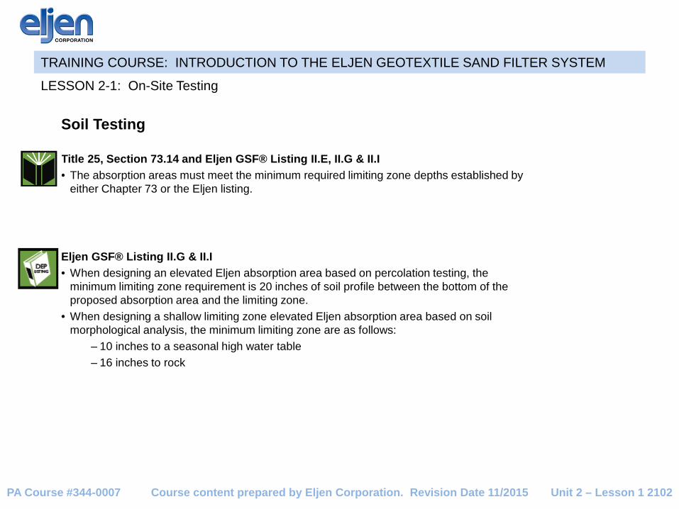
Treatment Tanks Eljen GSF® Listing II.B Tank Installations must be a rectangular two-compartment tank or two rectangular tanks in a series Round tanks are not permitted Installations in water table require control measures against floating tanks The outlet of the final tank or compartment must contain an effluent filter bearing the NSF seal
LESSON 3-1: Eljen GSF System Components
Unit 3 – Lesson 1 3102
An effluent filter with the NSF seal must be installed on the outlet of the last tank or compartment of the septic tank.
Round treatment tanks are not permitted with any alternate on-lot system.
Course content prepared by Eljen Corporation. Revision Date 11/2015 PA Course #344-0007
TRAINING COURSE: INTRODUCTION TO THE ELJEN GEOTEXTILE SAND FILTER SYSTEM
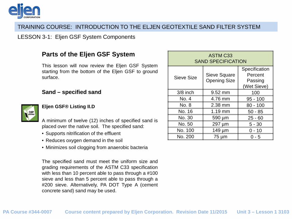
Parts of the Eljen GSF System
This lesson will now review the Eljen GSF System starting from the bottom of the Eljen GSF to ground surface. Sand – specified sand Eljen GSF® Listing II.D A minimum of twelve (12) inches of specified sand is placed over the native soil. The specified sand: • Supports nitrification of the effluent • Reduces oxygen demand in the soil • Minimizes soil clogging from anaerobic bacteria The specified sand must meet the uniform size and grading requirements of the ASTM C33 specification with less than 10 percent able to pass through a #100 sieve and less than 5 percent able to pass through a #200 sieve. Alternatively, PA DOT Type A (cement concrete sand) sand may be used.
LESSON 3-1: Eljen GSF System Components
Unit 3 – Lesson 1 3103
ASTM C33 SAND SPECIFICATION
Sieve Size Sieve Square Opening Size
Specification Percent Passing
(Wet Sieve) 3/8 inch 9.52 mm 100
No. 4 4.76 mm 95 - 100 No. 8 2.38 mm 80 - 100
No. 16 1.19 mm 50 - 85 No. 30 590 µm 25 - 60 No. 50 297 µm 5 - 30
No. 100 149 µm 0 - 10 No. 200 75 µm 0 - 5
Course content prepared by Eljen Corporation. Revision Date 11/2015 PA Course #344-0007

TRAINING COURSE: INTRODUCTION TO THE ELJEN GEOTEXTILE SAND FILTER SYSTEM
Parts of the Eljen GSF System
Eljen B43 GSF Modules Eljen GSF® Listing I
Only use Eljen B43 modules comprised of a cuspated plastic core that is woven with Bio-Matt geotextile fabric. This creates open-air channels within the module that support aerobic bacteria growth. Eljen GSF® Listing II.D
The dimensions of a B43 module: • 4 feet in length • 3 feet wide • 7 inches tall • Modules are placed end-to-end on top of specified
sand in an absorption area • A calculation must be done to determine the
number of modules that should be used in the filter system
• The modules may not be cut or otherwise resized
LESSON 3-1: Eljen GSF System Components
Unit 3 – Lesson 1 3104 Course content prepared by Eljen Corporation. Revision Date 11/2015 PA Course #344-0007

DISTRIBUTION PIPE Depending upon the absorption area established by the on-site testing results there may be up to two different distribution pipes required. In either gravity or pressure configurations a 4-inch- diameter standard perforated distribution pipe with holes
at the 4, 8 and optional 6 o’clock positions is centered above the modules and held in place with wire clamps. Gravity Flow Distribution A gravity flow system uses a 4-inch standard perforated distribution pipe with holes at the 4 and 8 o’clock positions only
LESSON 3-1: Eljen GSF System Components
Unit 3 – Lesson 1 3105
A 4-inch perforated distribution pipe is installed on top of the Eljen B43 modules.
TRAINING COURSE: INTRODUCTION TO THE ELJEN GEOTEXTILE SAND FILTER SYSTEM
Course content prepared by Eljen Corporation. Revision Date 11/2015 PA Course #344-0007

TRAINING COURSE: INTRODUCTION TO THE ELJEN GEOTEXTILE SAND FILTER SYSTEM
DISTRIBUTION PIPE Pressure Distribution A 1.5-inch low-pressure pipe must be inserted inside the 4-inch standard perforated distribution pipe Low-pressure pipe: • Conform to Title 25, Section 73.44 as clarified in the Eljen
design manual. • Orifice openings must be placed at the 12 o’clock position
on the low-pressure pipe • One 1/4-inch diameter drain hole must be drilled at the 6
o’clock position of each lateral • The distance from the last hole in the lateral to the end of
the lateral shall be equal to the distance from the edge of the first module to the first hole.
Pressure distribution is required in the following instances: 1. All elevated absorption area systems 2. When the percolation rate exceeds 60 min/in 3. All systems having a total absorption areas in excess
of 2,500 square feet
LESSON 3-1: Eljen GSF System Components
Unit 3 – Lesson 1 3106
Pipe and perforated pipe hole arrangement for pressure applications.
FROM PUMPCHAMBER
4" PERFORATED PIPE (SDR 35 OR BETTER)
90 DEGREECLEANOUT
GSF UNIT ATEND OF ROW
ASTM C33SAND
LOW PRESSUREPIPE
4" DIAMETER PERFORATED PIPE(SDR 35 OR BETTER)WITH HOLES AT 4, 6 & 8 O'CLOCK
LOW PRESSURE PIPE (SIZE PER DESIGN)
PRESSURE PIPE CROSS SECTION FOR ALL APPLICATIONS
ORIFICE
4" PERFORATED PIPE (SDR 35 OR BETTER)WITH HOLES AT 4, 6 & 8 O'CLOCK 4" END CAP
INSERT 1-1/2" SCH 40 PRESSURE LINE THROUGH END CAP
Course content prepared by Eljen Corporation. Revision Date 11/2015 PA Course #344-0007

TRAINING COURSE: INTRODUCTION TO THE ELJEN GEOTEXTILE SAND FILTER SYSTEM
DISTRIBUTION PIPE Distribution Pipe Perforations (pressure systems only) The 4 inch distribution pipe (SDR-35 or better) may have perforations that conform to either: Option 1) Pipe purchased from a manufacturer shall have a 3-hole perforation with 5/8” diameter holes
located at the 4 o’clock, 6 o’clock, and 8 o’clock positions
LESSON 3-1: Eljen GSF System Components
Unit 3 – Lesson 1 3107
B43 MODULEB43 MODULE B43 MODULE
5" 5" 5" 5" 5"5" 5" 5"
PERFORATIONSAT 6:00 POSITION
3-hole manufactured pipe
Course content prepared by Eljen Corporation. Revision Date 11/2015 PA Course #344-0007

TRAINING COURSE: INTRODUCTION TO THE ELJEN GEOTEXTILE SAND FILTER SYSTEM
DISTRIBUTION PIPE Distribution Pipe Perforations (pressure systems only)
Option 2) Pipe purchased from a manufacturer shall have
a 2-hole perforation with 5/8 diameter holes located at the 4 o’clock and 8 o’clock positions.
Additional perforations at the 6 o’clock position are acceptable provided that there are three 6 o’clock perforations in the pipe for each B43 module.
The perforations shall be placed such that the first hole be placed 8” from the end of the B43 module.
Subsequent perforations shall be placed 16” center to center.
The diameter of the perforations at the 6 o’clock shall be either 5/8 diameter or 3/4 diameter.
LESSON 3-1: Eljen GSF System Components
Unit 3 – Lesson 1 3108
8"
B43 MODULEB43 MODULE B43 MODULE
8" 16"16" 8" 8"
INSTALLER DRILLS PERFORATIONS AT 6:00POSITION MARKEDFROM EDGE OF EACH MODULE
2-hole manufactured pipe with holes drilled by contractor at 6 o’clock
Course content prepared by Eljen Corporation. Revision Date 11/2015 PA Course #344-0007
TRAINING COURSE: INTRODUCTION TO THE ELJEN GEOTEXTILE SAND FILTER SYSTEM
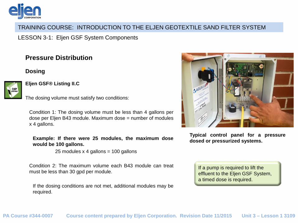
Pressure Distribution
Dosing
Eljen GSF® Listing II.C The dosing volume must satisfy two conditions:
Condition 1: The dosing volume must be less than 4 gallons per dose per Eljen B43 module. Maximum dose = number of modules x 4 gallons.
Example: If there were 25 modules, the maximum dose would be 100 gallons. 25 modules x 4 gallons = 100 gallons
Condition 2: The maximum volume each B43 module can treat must be less than 30 gpd per module.
If the dosing conditions are not met, additional modules may be required.
LESSON 3-1: Eljen GSF System Components
Unit 3 – Lesson 1 3109
Typical control panel for a pressure dosed or pressurized systems.
If a pump is required to lift the effluent to the Eljen GSF System, a timed dose is required.
Course content prepared by Eljen Corporation. Revision Date 11/2015 PA Course #344-0007

TRAINING COURSE: INTRODUCTION TO THE ELJEN GEOTEXTILE SAND FILTER SYSTEM
Parts of the Eljen GSF System Barrier material – anti-siltation fabrics An anti-siltation geotextile fabric covers the top and sides of the Eljen GSF modules. This geotextile fabric: • Protects the modules and specified sand from fines • Maintains effluent storage within the module • Provided by manufacturer
Cover material • Minimum of 8 inches deep • Meet the specifications in Title 25, Section 73.52(b)(14 and 15) • Protects the system and prevents erosion • If cover material is greater than 18 inches, the system requires
venting
LESSON 3-1: Eljen GSF System Components
Unit 3 – Lesson 1 3110
The anti-siltation geotextile fabric is installed over the distribution pipe and modules.
If a pump is required to lift the effluent to the Eljen GSF System, a timed dose is required.
The cover material has been placed over the absorption area and seeded.
Course content prepared by Eljen Corporation. Revision Date 11/2015 PA Course #344-0007
TRAINING COURSE: INTRODUCTION TO THE ELJEN GEOTEXTILE SAND FILTER SYSTEM
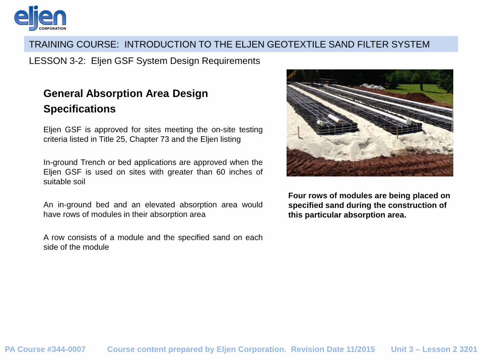
General Absorption Area Design Specifications
Eljen GSF is approved for sites meeting the on-site testing criteria listed in Title 25, Chapter 73 and the Eljen listing In-ground Trench or bed applications are approved when the Eljen GSF is used on sites with greater than 60 inches of suitable soil An in-ground bed and an elevated absorption area would have rows of modules in their absorption area A row consists of a module and the specified sand on each side of the module
LESSON 3-2: Eljen GSF System Design Requirements
Unit 3 – Lesson 2 3201
Four rows of modules are being placed on specified sand during the construction of this particular absorption area.
Course content prepared by Eljen Corporation. Revision Date 11/2015 PA Course #344-0007
TRAINING COURSE: INTRODUCTION TO THE ELJEN GEOTEXTILE SAND FILTER SYSTEM
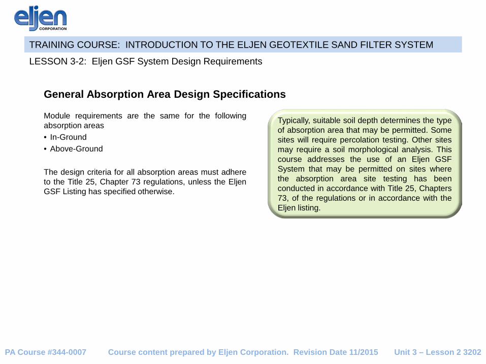
Module requirements are the same for the following absorption areas • In-Ground • Above-Ground The design criteria for all absorption areas must adhere to the Title 25, Chapter 73 regulations, unless the Eljen GSF Listing has specified otherwise.
LESSON 3-2: Eljen GSF System Design Requirements
Typically, suitable soil depth determines the type of absorption area that may be permitted. Some sites will require percolation testing. Other sites may require a soil morphological analysis. This course addresses the use of an Eljen GSF System that may be permitted on sites where the absorption area site testing has been conducted in accordance with Title 25, Chapters 73, of the regulations or in accordance with the Eljen listing.
Unit 3 – Lesson 2 3202
General Absorption Area Design Specifications
Course content prepared by Eljen Corporation. Revision Date 11/2015 PA Course #344-0007

TRAINING COURSE: INTRODUCTION TO THE ELJEN GEOTEXTILE SAND FILTER SYSTEM
LESSON 3-2: Eljen GSF System Design Requirements
Unit 3 – Lesson 2 3203
General Absorption Area Design Specifications .
Diagram of typical Eljen GSF installations for either an elevated or in-ground absorption area.
SPECIFIED SAND
SPECIFIED SAND
GEOTEXTILE FABRIC
ELEVATED ELJEN ABSORPTION AREA
IN GROUND TRENCH
Course content prepared by Eljen Corporation. Revision Date 11/2015 PA Course #344-0007

TRAINING COURSE: INTRODUCTION TO THE ELJEN GEOTEXTILE SAND FILTER SYSTEM
LESSON 3-2: Eljen GSF System Design Requirements
Unit 3 – Lesson 2 3204
General Absorption Area Design Specifications .
Diagram of typical Eljen GSF installations for either an elevated absorption area or in-ground absorption area.
SPECIFIED SAND
SPECIFIED SAND
ELEVATED ABSORPTION AREA
IN GROUND BED SYSTEM
Course content prepared by Eljen Corporation. Revision Date 11/2015 PA Course #344-0007

TRAINING COURSE: INTRODUCTION TO THE ELJEN GEOTEXTILE SAND FILTER SYSTEM
LIMITING ZONES ≥ 20 INCHES
Standard Eljen Configurations Percolation Rate = 3 to 60 min/in Minimum Specified Sand
• 12 inches under the modules • 6 inches at the ends of the modules • 6 inches on the sides of the modules
LESSON 3-2: Eljen GSF System Design Requirements
Unit 3 – Lesson 2 3205
The Eljen listing requires a minimum of two laterals per absorption area.
Standard Eljen Configurations for percolation rates ranging from 3 min/in to 60 min/in.
48"36"6" 6"
SPECIFIED SAND
GEOTEXTILE FABRICMIN 8"
OF COVER
7"
12"19"
Course content prepared by Eljen Corporation. Revision Date 11/2015 PA Course #344-0007
TRAINING COURSE: INTRODUCTION TO THE ELJEN GEOTEXTILE SAND FILTER SYSTEM
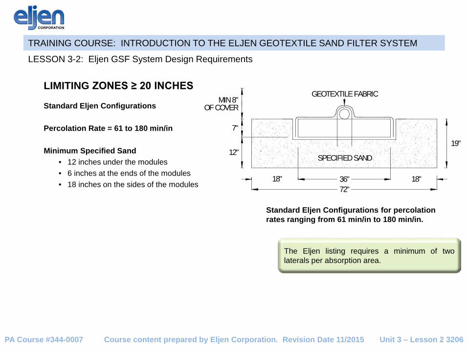
LIMITING ZONES ≥ 20 INCHES
Standard Eljen Configurations Percolation Rate = 61 to 180 min/in Minimum Specified Sand
• 12 inches under the modules • 6 inches at the ends of the modules • 18 inches on the sides of the modules
LESSON 3-2: Eljen GSF System Design Requirements
Unit 3 – Lesson 2 3206
Standard Eljen Configurations for percolation rates ranging from 61 min/in to 180 min/in.
72"36"18" 18"
SPECIFIED SAND
GEOTEXTILE FABRICMIN 8"
OF COVER
7"
12"19"
The Eljen listing requires a minimum of two laterals per absorption area.
Course content prepared by Eljen Corporation. Revision Date 11/2015 PA Course #344-0007

TRAINING COURSE: INTRODUCTION TO THE ELJEN GEOTEXTILE SAND FILTER SYSTEM
LIMITING ZONES ≥ 20 INCHES
Configuration of Beds Percolation Rate = 3 to 60 min/in
LESSON 3-2: Eljen GSF System Design Requirements
Unit 3 – Lesson 2 3207
The minimum depth of specified sand below the GSF module is 12 inches.
Minimum Specified Sand • 12 inches under the modules • 6 inches at the ends of the modules • 6 inches on the sides of the modules
(6 inches + 6 inches = 12 inches between rows of modules)
Course content prepared by Eljen Corporation. Revision Date 11/2015 PA Course #344-0007

TRAINING COURSE: INTRODUCTION TO THE ELJEN GEOTEXTILE SAND FILTER SYSTEM
LIMITING ZONES ≥ 20 INCHES
Configuration of Beds Percolation Rate = 61 to 180 min/in
LESSON 3-2: Eljen GSF System Design Requirements
Unit 3 – Lesson 2 3208
Minimum Specified Sand • 12 inches under the modules • 6 inches at the ends of the modules • 18 inches on sides of the modules
(18 inches + 18 inches = 36 inches between rows of modules)
The minimum depth of specified sand below the GSF module is 12 inches.
Course content prepared by Eljen Corporation. Revision Date 11/2015 PA Course #344-0007

TRAINING COURSE: INTRODUCTION TO THE ELJEN GEOTEXTILE SAND FILTER SYSTEM
LIMITING ZONES < 20 INCHES Shallow Limiting Zone Absorption Area Configuration (less than 20 inches of suitable soil) When siting the Eljen GSF on a shallow limiting elevated absorption area, the following criteria are applicable: A qualified soil scientist will use the Hydraulic Linear Loading Rate (HLLR) table found as Table 1 of the listing to determine the absorption area length and width A minimum of 6 inches of specified sand must be placed on the sides of the modules. If the 6 inches on each side of the module (12 inches total) and the 3-foot module do not equal the width determined by the HLLR chart, then additional sand must be added until the required width is reached. A minimum of 12 inches of specified sand must be placed underneath the modules. A minimum of 6 inches of specified sand must be placed at the ends of the modules.
LESSON 3-2: Eljen GSF System Design Requirements
Unit 3 – Lesson 2 3209 Course content prepared by Eljen Corporation. Revision Date 11/2015 PA Course #344-0007

TRAINING COURSE: INTRODUCTION TO THE ELJEN GEOTEXTILE SAND FILTER SYSTEM
General Absorption Area Design Specifications
SURFACE WATER DIVERSION Eljen GSF® Listing II.L The area surrounding the tanks and the absorption areas must be constructed to divert surface water away from the absorption area.
LESSON 3-2: Eljen GSF System Design Requirements
Unit 3 – Lesson 2 3210 Course content prepared by Eljen Corporation. Revision Date 11/2015 PA Course #344-0007

TRAINING COURSE: INTRODUCTION TO THE ELJEN GEOTEXTILE SAND FILTER SYSTEM
Calculating Number of Modules The number of modules required in a system will be calculated for sites with suitable soils of at least 20 inches and those with less than 20 inches.
≥ 20 inches of suitable soil To determine the number of modules required for an absorption area on a site with 20 inches or more of suitable soil, the total square feet of required absorption area is calculated using the Title 25, Section 73.16, Table A. The percolation rate (min/in) and the peak daily flow (gpd) from Title 25, Section 73.17 will be needed to perform this calculation.
LESSON 3-2: Eljen GSF System Design Requirements
Unit 3 – Lesson 2 3211
Calculating the Minimum Required Square Footage of an Absorption Area Title 25, Section 73.16, Table A Examples: #1) In-ground Bed
Percolation rate = 28 min/in Peak daily flow = 400 gpd (28 min/in - 15) x (0.040) + (1.19) = 1.71 sq ft/gal 1.71 sq ft/gal x 400 gpd = 684 sq ft
#2) Elevated Bed
Percolation rate = 62 min/in Peak daily flow = 400 gpd (62 min/in - 60) x (0.020) + (2.22) = 2.26 sq ft/gal 2.26 sq ft/gal x 400 gpd = 904 sq ft
Course content prepared by Eljen Corporation. Revision Date 11/2015 PA Course #344-0007

TRAINING COURSE: INTRODUCTION TO THE ELJEN GEOTEXTILE SAND FILTER SYSTEM
≥ 20 INCHES OF SUITABLE SOIL
A 40 Percent Absorption Area Size Reduction is allowed when the percolation rate is between 3 to 60 min/inch percolation rates
40% reduction taken off total square foot requirement is taken into account using the following formulas 40% reduction = total sq ft of absorption area x (1.00-0.40) OR 40% reduction = total sq ft of absorption area x 0.60
LESSON 3-2: Eljen GSF System Design Requirements
Unit 3 – Lesson 2 3212
Calculating 40 Percent Reduction in an Absorption Area Title 25, Section 73, Table A Examples: #1) In-ground Bed
Percolation rate = 28 min/in Peak daily flow = 400 gpd (28 min/in - 15) x (0.04) + (1.19) = 1.71 sq ft/gal 1.71 sq ft/gal x 400 gpd = 684 sq ft 684 sq ft x 0.60 = 411 sq ft
#2) Elevated Bed
Percolation rate = 62 min/in Peak daily flow = 400 gpd In this example, no reduction is allowed because the percolation rate is higher than the minimum 60 minutes per inch.
Course content prepared by Eljen Corporation. Revision Date 11/2015 PA Course #344-0007

TRAINING COURSE: INTRODUCTION TO THE ELJEN GEOTEXTILE SAND FILTER SYSTEM
Calculating Number of Modules (w/o size reduction)
≥ 20 INCHES OF SUITABLE SOIL Eljen GSF® Listing II.D Effective Bottom Absorption Area To calculate the minimum number of modules necessary for an Eljen GSF System, the total square feet of the absorption area is divided by the effective bottom absorption area of the modules. The value of the effective bottom absorption area depends on the percolation rate. It could be either:
• 16 square feet per module if the percolation rate is 3 to 60 min/in, or • 24 square feet per module if the percolation rate is 61 to 180 min/in
Minimum number of modules = absorption area square feet ÷ effective bottom absorption area of the modules Examples: (400 gpd peak daily flow)
1) Percolation rate = 28 min/in Total square feet = 684 sq ft Minimum number of modules = 684 sq ft ÷ 16 sq ft/module = 43 modules
2) Percolation rate = 62 min/in Total square feet = 904 sq ft Minimum number of modules = 904 sq ft ÷ 24 sq ft/module = 38 modules
LESSON 3-2: Eljen GSF System Design Requirements
Unit 3 – Lesson 2 3213
If the calculation used to determine the number of required modules comes out to a fraction, round up to the nearest whole number. Modules cannot be cut or otherwise resized.
Course content prepared by Eljen Corporation. Revision Date 11/2015 PA Course #344-0007
TRAINING COURSE: INTRODUCTION TO THE ELJEN GEOTEXTILE SAND FILTER SYSTEM
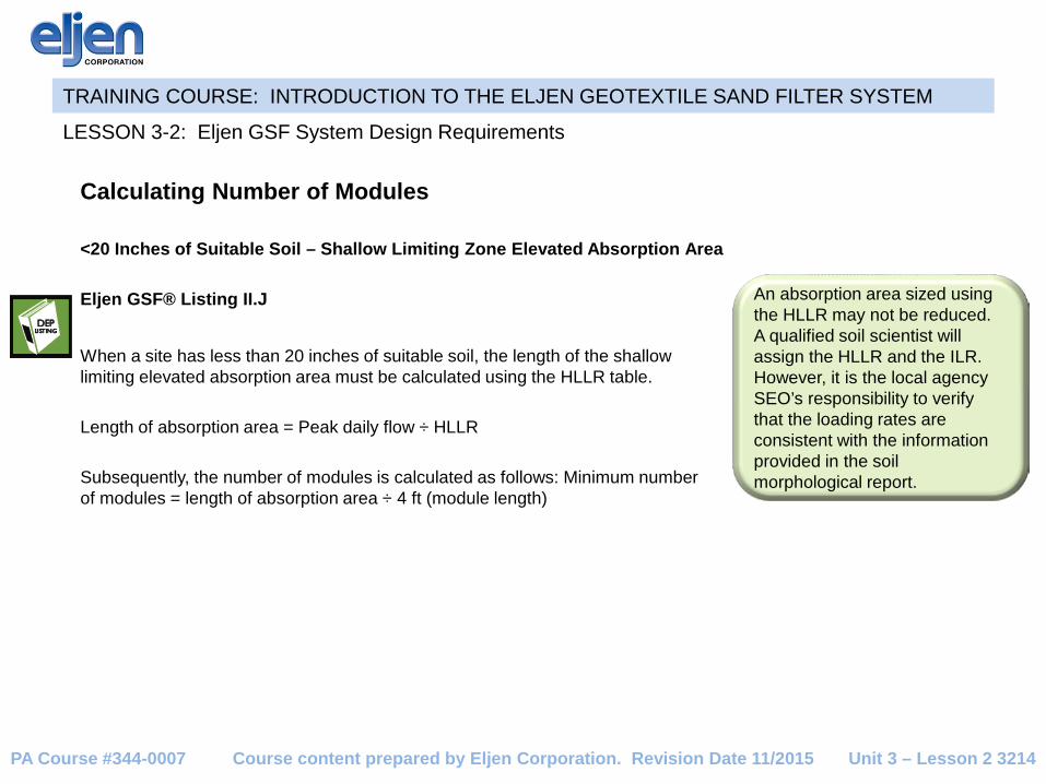
Calculating Number of Modules <20 Inches of Suitable Soil – Shallow Limiting Zone Elevated Absorption Area Eljen GSF® Listing II.J
LESSON 3-2: Eljen GSF System Design Requirements
Unit 3 – Lesson 2 3214
An absorption area sized using the HLLR may not be reduced. A qualified soil scientist will assign the HLLR and the ILR. However, it is the local agency SEO’s responsibility to verify that the loading rates are consistent with the information provided in the soil morphological report.
When a site has less than 20 inches of suitable soil, the length of the shallow limiting elevated absorption area must be calculated using the HLLR table. Length of absorption area = Peak daily flow ÷ HLLR Subsequently, the number of modules is calculated as follows: Minimum number of modules = length of absorption area ÷ 4 ft (module length)
Course content prepared by Eljen Corporation. Revision Date 11/2015 PA Course #344-0007

TRAINING COURSE: INTRODUCTION TO THE ELJEN GEOTEXTILE SAND FILTER SYSTEM
Calculating Number of Modules <20 Inches of Suitable Soil – Shallow Limiting Zone Elevated Absorption Area
LESSON 3-2: Eljen GSF System Design Requirements
Unit 3 – Lesson 2 3215
Example: HLLR = 3.5 gal/ft/day Peak daily flow = 400 gpd for three bedrooms
1) Length of absorption area = Peak daily flow ÷ HLLR 400 gpd ÷ 3.5 gal/ft/day = 114.3, round up to 115 linear feet
2) Minimum number of B43 modules = length of absorption area ÷ 4 ft (module length) 115 ft ÷ 4 ft = 28.75 modules, round to 29 modules
Course content prepared by Eljen Corporation. Revision Date 11/2015 PA Course #344-0007

TRAINING COURSE: INTRODUCTION TO THE ELJEN GEOTEXTILE SAND FILTER SYSTEM
DESIGN SUMMARY TABLE
LESSON 3-2: Eljen GSF System Design Requirements
Unit 3 – Lesson 2 3216
Percolation RateReduction Allowed
GSF Module Area (ft2)
Sand PerimeterSand at the
Ends of RowSand Between Module Rows
3 min/in to 60 min/in Up to 40% 16 Min 6" Min 6" Min 12"61 min/in to 180 min/in No 24 Min 18" Min 6" Min 36"
HLLR table Nocalculate using HLLR table
Total width of absorption area must be rounded up to nearest whole number
Min 6" Not Applicable
Course content prepared by Eljen Corporation. Revision Date 11/2015 PA Course #344-0007

TRAINING COURSE: INTRODUCTION TO THE ELJEN GEOTEXTILE SAND FILTER SYSTEM
Calculating Length and Width for Limiting Zone with ≥ 20 Inches of Suitable Soil
The final design square footage is dependent on the total number of required modules and corresponding specified sand dimensions. These requirements will determine the proposed absorption area’s length and width.
Length of the Absorption Area
To complete the final length calculation, the number of modules and the number of runs or rows must be known. This was covered in Lesson 3-2. The actual number of individual runs or rows will be determined by the proposed site and the corresponding area available for installation as well as the slope. The minimum length:width ratios for elevated systems are 4:1 for slopes > 8% but < 12% and 6:1 for slopes from 12 to 15%.
Gravity Flow and End Fed Pressure Distribution
Length of absorption area = number of modules x 4 ft (module length) + 1 ft (6 inches of specified sand on each lateral end) Example: 10 (modules) x 4 ft + 1 ft = 41 ft
Pressure Distribution and Central Manifold Distribution Length of absorption area =
number of modules x 4 ft (module length) + 1 ft (6 inches of specified sand on each lateral end) + .5 ft (manifold lateral offset if using center feed manifold) Example: 10 (modules) x 4 ft + 1 ft + .5 ft = 41.5 ft
LESSON 3-3: Eljen GSF System Absorption Area Configurations
Unit 3 – Lesson 3 3301 Course content prepared by Eljen Corporation. Revision Date 11/2015 PA Course #344-0007
TRAINING COURSE: INTRODUCTION TO THE ELJEN GEOTEXTILE SAND FILTER SYSTEM
Calculating Length and Width for Limiting Zone With >20 Inches of Suitable Soil Width of the run To complete the width calculation, the average percolation rate is used. The rate will determine the inches of specified sand that must be placed on each side of the module. This sand width added to the standard 3-foot width of the module will provide the total width of the run. The run will be either a minimum of 4 feet wide (if the percolation rate is 3 to 60 minutes per inch) or a minimum of 6 feet wide (if the percolation rate is 61 to 180 minutes per inch). To determine the bed width, multiply the row width by the number of rows. Percolation Rate 3-60 Minutes Per Inch
Minimum width of run = 4 feet 3 ft (module width) + 1 ft (6 inches of specified sand on each side of module)
Percolation Rate 61-180 Minutes Per Inch
Minimum width of run = 6 feet 3 ft (module width) + 3 ft (18 inches of specified sand on each side of module)
LESSON 3-3: Eljen GSF System Absorption Area Configurations
Unit 3 – Lesson 3 3302 Course content prepared by Eljen Corporation. Revision Date 11/2015 PA Course #344-0007

TRAINING COURSE: INTRODUCTION TO THE ELJEN GEOTEXTILE SAND FILTER SYSTEM
Calculating Length and Width for Limiting Zone With <20 Inches of Suitable soil
On sites with less than 20 inches of suitable soil, the shallow limiting zone elevated absorption area must be used. The soil morphological analysis and corresponding hydraulic linear loading rate (HLLR) table will determine the length and width of this absorption area. Minimum system length for a system design using the HLLR table is calculated by dividing peak daily flow (gpd) by the HLLR. The shallow limiting zone elevated absorption area must be pressure dosed. Pressure Distribution End Manifold Configuration - Length of absorption area =
number of modules in an absorption area x 4 ft (module length) + 1 ft (6 inches of specified sand on each lateral end)
Central Manifold Configuration - Length of absorption area =
number of modules in an absorption area x 4 ft (module length) + 1 ft (6 inches of specified sand on each lateral end) + .5 ft (manifold lateral offset)
LESSON 3-3: Eljen GSF System Absorption Area Configurations
Unit 3 – Lesson 3 3303 Course content prepared by Eljen Corporation. Revision Date 11/2015 PA Course #344-0007

TRAINING COURSE: INTRODUCTION TO THE ELJEN GEOTEXTILE SAND FILTER SYSTEM
Calculating Length and Width for Limiting Zone <20 Inches of Suitable soil
LESSON 3-3: Eljen GSF System Absorption Area Configurations
Unit 3 – Lesson 3 3304
The HLLR and the ILR will be provided by the qualified soil scientist. However, it is the local agency SEO’s responsibility to verify that the loading rates are consistent with the information provided in the soil morphological report.
Pressure Distribution Width of absorption area
The HLLR and the infiltration loading rate (ILR) from the HLLR table will provide the minimum width of the absorption area. If the width that results from the table is less than 4 feet, the required 6 inches of sand on both sides of the module must still be used. Therefore, the minimum absorption area width is 4 feet. If the width is more than 4 feet, then additional sand will be required to meet the width required by the HLLR table. Example: Required width (according to HLLR) = 4.5 feet Round to nearest whole number Required minimum width = 5 feet 5.0 ft. - 3 ft module = 2.0 ft of additional sand
Course content prepared by Eljen Corporation. Revision Date 11/2015 PA Course #344-0007

TRAINING COURSE: INTRODUCTION TO THE ELJEN GEOTEXTILE SAND FILTER SYSTEM
Example #1: An Elevated Absorption Area Pressure Dosing Design Percolation Rate – 31 min/in House size – 3 bedrooms Design Flow – 400 gpd (Chapter 73.17)
A) Determine the square feet of Absorption Area per gallon per day: Absorption area (ft2) based on the percolation rate and peak daily flow For a percolation rate of 31 min/in: ((Avg. Perc Rate - 30) x (0.026) + 1.50)) = 1.53 ft2 per gallon (gal) Absorption area for 3 bedroom: 400 gal/day x 1.53 ft2 /gal = 612 ft2 Reduce Absorption Area by 40%: 610 ft2 x (1 – 0.4) = 368 ft2.
B) Determine number of modules: The B43 Module Basal Area is 16 ft2 for percolation rates between 3 min/in – 60 min/in Number of Modules = Reduced Trench Area ÷ B43 Basal Area: 368 ft2 ÷ 16 ft2 = 23.0, use a minimum of 23 Modules
LESSON 3-3: Eljen GSF System Absorption Area Configurations
Unit 3 – Lesson 3 3305 Course content prepared by Eljen Corporation. Revision Date 11/2015 PA Course #344-0007

TRAINING COURSE: INTRODUCTION TO THE ELJEN GEOTEXTILE SAND FILTER SYSTEM
Example #1: An Elevated Absorption Area Pressure Dosing Design (End feed)
C) Calculate Absorption Area Length: (# of Mod ÷ # of Rows x 4 ft) + 1 ft of Specified Sand = Absorption Area Length End feed: 2 Rows: 23 Mods ÷ 2 Rows = 11.5 Mods, use 12 Modules: 12 Mods x 4 ft + 1 ft = 49 ft Absorption Area Length
D) Calculate Approximate Run Width (For this example, we decided to use two rows): The minimum width is 4 ft per row for percolation rates 3 – 60 min/in. Since this system uses two rows, the minimum width is 4 ft x 2 rows = 8 ft.
LESSON 3-3: Eljen GSF System Absorption Area Configurations
Unit 3 – Lesson 3 3306
SEPTIC
TANK
SPECIFIED SAND
4" DISTRIBUTION PIPE
PUMP
CHAMBER
6"
B43 / 36"
49'
PRESSURE LINE PER CODE
8'
The minimum length:width ratios for elevated systems are 4:1 for slopes > 8% but < 12% and 6:1 for slopes from 12 to 15%.
Course content prepared by Eljen Corporation. Revision Date 11/2015 PA Course #344-0007

TRAINING COURSE: INTRODUCTION TO THE ELJEN GEOTEXTILE SAND FILTER SYSTEM
Example #1: An Elevated Absorption Area Pressure Dosing Design (Central Manifold)
C) Calculate Absorption Area Length: (# of Mod ÷ # of Rows x 4 ft) + 1 ft of Specified Sand + 0.5 ft (Lateral Offset) = Absorption Area Length Central Manifold: 2 Rows: 23 Mods ÷ 2 Rows = 11.5 Mods, use 12 Modules: 12 Mods x 4 ft + 1 ft + 0.5 ft = 49.5 ft Absorption Area Length
D) Calculate Approximate Absorption Area Width (For this example, we decided to use two rows): The minimum width is 4 ft per row for percolation rates 3 – 60 min/in. Since this system uses two rows, the minimum width is 4 ft x 2 rows = 8 ft.
LESSON 3-3: Eljen GSF System Absorption Area Configurations
Unit 3 – Lesson 3 3307
SEPTIC
TANKSPECIFIED SAND
PUMP
CHAMBER
6"
B43 / 36"
3" MIN
49.5'
4' 8'
6" MIN
2'
PRESSURE LINE PER CODE4" DISTRIBUTION PIPE
Eljen GSF units sit on either a 4 foot bench or 6 foot step depending on the percolation rate. For percolation rates < 60 mpi, use a 4 foot step.
Course content prepared by Eljen Corporation. Revision Date 11/2015 PA Course #344-0007

TRAINING COURSE: INTRODUCTION TO THE ELJEN GEOTEXTILE SAND FILTER SYSTEM
Example #2: Shallow Limiting Zone Absorption Area (Less than 20 Inches from Limiting Horizon) House size – 3 bedrooms Design Flow – 400 gpd (Chapter 73.17) Slope on the Limiting Horizon – 12% Distance from Limiting Horizon – 15 in Soil Characteristics Texture - Silt Loam (SIL) Structure Shape - Fine – Sub angular - Blocky(BK) Grade - Friable - Weak (1)
A) Determine the Infiltration Loading Rate (gal/ft2/day): Refer to the Hydraulic Linear Loading Rate Table 1 of the Eljen listing to determine the Infiltration Loading Rate. Use the Soil Characteristics to determine the rate. 0.6 gal/ft2/day
B) Determine the Hydraulic Linear Loading Rate (gal/ft/day): Refer to the Hydraulic Linear Loading Rate Table 1 of the Eljen listing to determine the Hydraulic Linear Loading Rate. Use the Infiltration Loading Rate and information about the Limiting Horizon to determine the rate. 3.5 gal/ft/day
LESSON 3-3: Eljen GSF System Absorption Area Configurations
Unit 3 – Lesson 3 3308 Course content prepared by Eljen Corporation. Revision Date 11/2015 PA Course #344-0007

TRAINING COURSE: INTRODUCTION TO THE ELJEN GEOTEXTILE SAND FILTER SYSTEM
LESSON 3-3: Eljen GSF System Absorption Area Configurations
Unit 3 – Lesson 3 3309
C) Determine Required Length of Bed: (Design Flow ÷ Hydraulic Linear Loading Rate) (400 gpd ÷ 3.5 gpd/ft) = 114.3 ft, round up to 115 ft D) Determine Width of Bed: Hydraulic Linear Loading Rate ÷ Infiltration Loading Rate Bed width cannot be less than 4 ft. If the required trench width is smaller, increase to a 4 ft width, otherwise round up to the nearest whole foot. 3.5 gpd/ft ÷ 0.6 gpd/ft2 = 5.8 ft, round up to 6 ft E) Calculate the Number of Modules: Number of Modules = Trench Length ÷ 4 ft/module Number of Modules = 115 ÷ 4 ft = 28.75 Modules, round up to 29
Course content prepared by Eljen Corporation. Revision Date 11/2015 PA Course #344-0007

TRAINING COURSE: INTRODUCTION TO THE ELJEN GEOTEXTILE SAND FILTER SYSTEM
LESSON 3-3: Eljen GSF System Absorption Area Configurations
Unit 3 – Lesson 3 3310
312
112" MIN
12" MIN6.0'
2.5'
SPECIFIED SAND
12 % SLOPE
6" MIN
SEPTIC
TANK
PUMP CHAMBERPRESSURE LINE PER CODE
SPECIFIED SAND 4" DISTRIBUTION PIPE
6'36"
6" MINON ENDS
117'
48"
End feed Calculations F) Determine Actual Trench Length: Modules x Length of Module + 1 ft of Specified Sand at row ends = 29 Modules x 4 ft + 1 ft = 117 ft G) Actual Absorption Area: Actual trench length x Width of Trench 117 ft x 6 ft = 702 ft2
Course content prepared by Eljen Corporation. Revision Date 11/2015 PA Course #344-0007

TRAINING COURSE: INTRODUCTION TO THE ELJEN GEOTEXTILE SAND FILTER SYSTEM
LESSON 3-3: Eljen GSF System Absorption Area Configurations
Unit 3 – Lesson 3 3311
312
112" MIN
12" MIN6.0'
2.5'
SPECIFIED SAND
12 % SLOPE
6" MIN
36"
4'
SEPTIC
TANK
SPECIFIED SAND
117.5'
6'
PUMP CHAMBER
6" MINON ENDS
4" DISTRIBUTION PIPEPRESSURE LINE PER CODE
Central Manifold Calculations F) Determine Actual Trench Length: Modules x Length of Module + 1 ft of Specified Sand at row ends + 0.5 ft Lateral Offset = 29 Modules x 4 ft + 1 ft + 0.5 ft = 117.5 ft G) Actual Absorption Area: Actual trench length x Width of Trench 117.5 ft x 6 ft = 705 ft2
Course content prepared by Eljen Corporation. Revision Date 11/2015 PA Course #344-0007
TRAINING COURSE: INTRODUCTION TO THE ELJEN GEOTEXTILE SAND FILTER SYSTEM
Calculating the Length, Width, and Final Square Feet of Absorption Areas Actual Absorption Area configurations Common Approved GSF Installation Options in Pennsylvania
1) Elevated absorption area, pressure distribution 2) Shallow limiting zone elevated absorption area 3) Trench, gravity distribution 4) Trench, pressure distribution 5) In ground bed, gravity distribution 6) In ground bed, pressure distribution
LESSON 3-3: Eljen GSF System Absorption Area Configurations
Unit 3 – Lesson 3 3312 Course content prepared by Eljen Corporation. Revision Date 11/2015 PA Course #344-0007

TRAINING COURSE: INTRODUCTION TO THE ELJEN GEOTEXTILE SAND FILTER SYSTEM
Absorption Area Installation STEP 1: Scarify Receiving Soil
• Scarify the receiving layer
• Absorption area should not be obstructed by stumps or other obstacles and shall be roughed or plowed parallel with the contour to a maximum depth of 6 inches (73.55b.(2))
• Avoid walking or any type of travel over the scarified soil before placing the specified sand to avoid soil compaction.
LESSON 4-1: Installation
Unit 4 – Lesson 1 4101
As with any other absorption area, the moisture level of the soil should be checked prior to installation.
The receiving layer of the absorption area is scarified by hand or with a backhoe. If system is installed below grade, use a hand rake to scarify absorption area side walls.
The receiving layer of the soil refers to the bottom of an excavated trench or seepage bed or the natural soil surface for an above ground absorption area.
Course content prepared by Eljen Corporation. Revision Date 11/2015 PA Course #344-0007

TRAINING COURSE: INTRODUCTION TO THE ELJEN GEOTEXTILE SAND FILTER SYSTEM
Absorption Area Installation STEP 2: Place specified sand
• Place 6 inches of specified sand and compact
• Place another 6 inches of specified sand on top and compacted
• A hand-tamping tool or vibrating compactor are both acceptable to use for compacting the sand
• The depth of compacted specified sand below the Eljen GSF modules must be a minimum of 12 inches
• The specified sand must be level
LESSON 4-1: Installation
Unit 4 – Lesson 1 4102
Twelve (12) inches of specified sand has been placed at the bottom of the system area and is compacted in 6 inch lifts by a vibratory plate compactor, hand tamping tool, or approved equivalent.
Course content prepared by Eljen Corporation. Revision Date 11/2015 PA Course #344-0007

TRAINING COURSE: INTRODUCTION TO THE ELJEN GEOTEXTILE SAND FILTER SYSTEM
Absorption Area Installation STEP 3: Place Eljen GSF Modules
• Place units end-to-end
• White Stripe up
LESSON 4-1: Installation
Unit 4 – Lesson 1 4103
Eljen B43 modules placed end-to-end in a bed configuration.
Course content prepared by Eljen Corporation. Revision Date 11/2015 PA Course #344-0007

TRAINING COURSE: INTRODUCTION TO THE ELJEN GEOTEXTILE SAND FILTER SYSTEM
Absorption Area Installation STEP 4: Install Distribution Pipe
LESSON 4-1: Installation
Unit 4 – Lesson 1 4104
One Eljen wire clamp per module is placed over the 4-inch distribution pipe to hold it in .
• Center the 4-inch perforated distribution pipe lengthwise over the modules
• Orifices are at the 4, 6 and 8 o’clock positions
• Secure pipe to module using Wire Clamp
Course content prepared by Eljen Corporation. Revision Date 11/2015 PA Course #344-0007
TRAINING COURSE: INTRODUCTION TO THE ELJEN GEOTEXTILE SAND FILTER SYSTEM
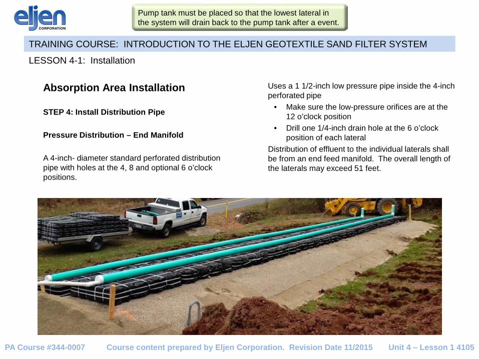
Absorption Area Installation STEP 4: Install Distribution Pipe Pressure Distribution – End Manifold A 4-inch- diameter standard perforated distribution pipe with holes at the 4, 8 and optional 6 o’clock positions.
LESSON 4-1: Installation
Unit 4 – Lesson 1 4105
Uses a 1 1/2-inch low pressure pipe inside the 4-inch perforated pipe
• Make sure the low-pressure orifices are at the 12 o’clock position
• Drill one 1/4-inch drain hole at the 6 o’clock position of each lateral
Distribution of effluent to the individual laterals shall be from an end feed manifold. The overall length of the laterals may exceed 51 feet.
Pump tank must be placed so that the lowest lateral in the system will drain back to the pump tank after a event.
Course content prepared by Eljen Corporation. Revision Date 11/2015 PA Course #344-0007

TRAINING COURSE: INTRODUCTION TO THE ELJEN GEOTEXTILE SAND FILTER SYSTEM
Absorption Area Installation STEP 4: Install Distribution Pipe Pressure Distribution – Central Manifold A 4-inch- diameter standard perforated distribution pipe with holes at the 4, 8 and optional 6 o’clock positions. Uses a 1 1/2-inch low pressure pipe inside the 4-inch perforated pipe
• Make sure the low-pressure orifices are at the 12 o’clock position
• Drill one 1/4-inch drain hole at the 6 o’clock position of each lateral
Distribution of effluent to the individual laterals shall be by a central manifold extending into the absorption area from the delivery pipe. The overall length of the laterals may exceed 51 feet.
LESSON 4-1: Installation
Unit 4 – Lesson 1 4106
LOW PRESSUREPIPE
4" DIAMETER PERFORATED PIPE(SDR 35 OR BETTER)WITH HOLES AT 4, 6 & 8 O'CLOCK
LOW PRESSURE PIPE (SIZE PER DESIGN)
ORIFICE
4" PERFORATED PIPE (SDR 35 OR BETTER)
Pump tank must be placed so that the lowest lateral in the system will drain back to the pump tank after a event.
Course content prepared by Eljen Corporation. Revision Date 11/2015 PA Course #344-0007

TRAINING COURSE: INTRODUCTION TO THE ELJEN GEOTEXTILE SAND FILTER SYSTEM
Absorption Area Installation STEP 5: Place barrier material To properly install the cover fabric:
A) Center the fabric over the perforated pipe and drape it over both sides
B) Shovel on specified sand directly over the distribution pipe
C) Repeat this step while moving along the pipe
D) Place specified sand along edges of modules to hold fabric in place
LESSON 4-1: Installation
Unit 4 – Lesson 1 4107
The cover fabric provided by the manufacturer is laid over the distribution pipe and modules.
Specified sand is placed along the sides of the perforated pipe and over the modules.
Course content prepared by Eljen Corporation. Revision Date 11/2015 PA Course #344-0007
TRAINING COURSE: INTRODUCTION TO THE ELJEN GEOTEXTILE SAND FILTER SYSTEM
Absorption Area Installation
STEP 6: Additional Construction Specifications
The absorption area shall be chisel plowed across the slope and under the berm as described in 73.55(b)(2).
The construction of the absorption area should also include a minimum slope of 2:1 on all sides of the sand.
In pressure configurations, the absorption area must be constructed using pressure-dosed distribution with lateral end cleanouts.
When the limiting zone is greater than or equal to 20 inches, the absorption area must also be sized in accordance with the requirements of 73.16(c), Table A, column labeled subsurface sand filters & elevated sand mounds.
Placing absorption areas in stacking configuration for new construction is prohibited. Berms are required to meet the requirements of Sections 73.55(b)(7), 73.55(d)(3), and 73.55(d)(4).
For elevated absorption areas only The recommended minimum length to width ratio for slopes ranging from 8 percent to 12 percent is 4:1 while slopes ranging from 12 percent to 15 percent may utilize a 6:1 length to width ratio or greater.
LESSON 4-1: Installation
Unit 4 – Lesson 1 4108 Course content prepared by Eljen Corporation. Revision Date 11/2015 PA Course #344-0007

TRAINING COURSE: INTRODUCTION TO THE ELJEN GEOTEXTILE SAND FILTER SYSTEM
Absorption Area Installation STEP 7: Place Cover Material Section 73.52(b)(14 & 15) • Place a minimum of 8 inches of soil cover over the
barrier material
• Make sure the soil cover material consists of soil suitable for the growth of vegetation
• Apply the cover material from the upslope side
• Do not use wheeled equipment over the absorption area. A light track machine may be used with caution.
• Avoid crushing or shifting any of the distribution pipes
• Seed and mulch to establish vegetative cover and control erosion
LESSON 4-1: Installation
Unit 4 – Lesson 1 4109
The local agency SEO must conduct a final inspection before the soil cover is placed over the system.
The cover material has been graded and seeded to prevent erosion. There is a vent pipe at the distal end of this absorption area. Venting is required when there is more than 18 inches of soil cover over the Eljen GSF filters.
Course content prepared by Eljen Corporation. Revision Date 11/2015 PA Course #344-0007
TRAINING COURSE: INTRODUCTION TO THE ELJEN GEOTEXTILE SAND FILTER SYSTEM
SEO Final Inspection The SEO must check the system to verify that it was installed according to the approved design. This final inspection must be done prior to placing the soil cover over the system. The Eljen Pennsylvania GSF Design and Installation Manual has a checklist to use during the final inspection.
LESSON 4-1: Installation
Go to www.eljen.com to obtain the Eljen Pennsylvania GSF Design and Installation Manual. The inspection checklist is included in the design and installation manual.
Unit 4 – Lesson 1 4110 Course content prepared by Eljen Corporation. Revision Date 11/2015 PA Course #344-0007

TRAINING COURSE: INTRODUCTION TO THE ELJEN GEOTEXTILE SAND FILTER SYSTEM
SEO Final Inspection Absorption Areas With Gravity Flow The items in the list below must be checked during the final inspection of the Eljen GSF System: 1) Verify each line or row of modules is level.
2) Ensure that the painted white stripes on the module are facing up.
3) Verify there is a minimum 12 inches of specified sand underneath each module in the system.
4) Based on the system design, verify the appropriate amount of specified sand is installed between module
rows in bed systems and along the 4-foot module length in trench systems.
5) Verify there is 6 inches of specified sand at the beginning and end of the module in a row or a trench configuration.
6) Verify the 4-inch perforated pipe on top of the modules is SDR-35 or equivalent.
7) Verify the pipe’s orifices are in accordance with the design.
8) Verify one wire clamp per module is installed over the 4-inch distribution pipe.
9) Verify the cover fabric is placed over the 4-inch perforated distribution pipe and draped over the sides of each module before specified sand is placed around the modules. The cover fabric must NOT be pulled tightly away from the 4-inch perforated pipe, because this causes tenting.
LESSON 4-1: Installation
Unit 4 – Lesson 1 4111 Course content prepared by Eljen Corporation. Revision Date 11/2015 PA Course #344-0007

TRAINING COURSE: INTRODUCTION TO THE ELJEN GEOTEXTILE SAND FILTER SYSTEM
SEO Final Inspection Absorption Areas With Pressure Distribution In addition to all the items previously covered in the gravity flow list, the following items must be verified during the final inspection of an Eljen GSF System when used with pressure distribution:
1) Verify the 1½ -inch low-pressure pipe has at least one 1/4-inch-diameter drain hole at the 6 o’clock position for
each lateral
2) Verify the 1 ½ -inch low-pressure pipe orifices are at the 12 o’clock position.
3) Verify the pipe’s orifices are in accordance with the design.
4) Confirm the on-lot system has 3 feet of head at the terminal end of the lateral.
5) For elevated absorption areas, verify the length and width ratio is a minimum of 4:1 for slopes ranging from 8 percent to 12 percent or 6:1 for slopes ranging 12 percent to 15 percent.
6) Verify there is minimum 2:1 approved sand slope on all sides or elevated systems.
7) Verify the berms meet the requirements of Section 73.55(b)(7), 73.55(d)(3), and 73.55(d)(4).
8) Verify the inclusion of lateral end cleanout.
LESSON 4-1: Installation
Unit 4 – Lesson 1 4112 Course content prepared by Eljen Corporation. Revision Date 11/2015 PA Course #344-0007

TRAINING COURSE: INTRODUCTION TO THE ELJEN GEOTEXTILE SAND FILTER SYSTEM
System Start-up Requirements • Manufacturer’s representative must schedule a meeting with the property owner in first month of start-up
• Explain Operation and Maintenance
• Location of all parts of the system
• Recommend that the manufacturer be contacted if the pump alarm is activated
• Provide a copy of the GSF Septic System Owner’s Manual
• Written commitment that Eljen will investigate and troubleshoot system problems when notified
LESSON 4-1: Installation
Unit 4 – Lesson 1 4113 Course content prepared by Eljen Corporation. Revision Date 11/2015 PA Course #344-0007

TRAINING COURSE: INTRODUCTION TO THE ELJEN GEOTEXTILE SAND FILTER SYSTEM
Minimum Required Maintenance Standards A maintenance agreement is not a requirement for Eljen permit issuance and the manufacturer should determine the frequency of maintenance activities as specified in the Eljen System owner’s manual. Eljen recommends that the maintenance activities and frequency for Geotextile Sand Filter systems be equal to the maintenance activities and frequency specified by the local agency for Elevated Sand mounds. Homeowner Inspection Eljen GSF® Listing III.C The property owner must inspect an on-lot system with an Eljen GSF System every six months. During this inspection, the property owner should verify that there is no ponding of effluent around the absorption area and no down gradient seepage.
LESSON 5-1: Maintenance
Unit 5 – Lesson 1 5001
Every six months the property owner must inspect the area around the absorption area to ensure that there is no ponding or seepage. No evidence of ponding is shown in this photo of a shallow limiting zone elevated absorption area.
Course content prepared by Eljen Corporation. Revision Date 11/2015 PA Course #344-0007

TRAINING COURSE: INTRODUCTION TO THE ELJEN GEOTEXTILE SAND FILTER SYSTEM
Manufacturer Information The Eljen B43 GSF module is manufactured by the Eljen Corporation based in Connecticut. For additional information, questions, technical assistance, or distributor locations, please contact: Eljen Corporation 125 McKee St. East Hartford, CT 06108 Tel: 800-444-1359 Fax: 860-610-0427 Email: [email protected] http://www.eljen.com
LESSON 5-1: Maintenance
Unit 5 – Lesson 1 5002 Course content prepared by Eljen Corporation. Revision Date 11/2015 PA Course #344-0007