Embed Size (px)
Citation preview

1
Vol. 8 No. 4, 2008
In This Issue Back to Basics - Defrost 1-13
Upcoming Ammonia Classes 2
Noteworthy 2
IRC Staff Director Doug Reindl 608/265-3010 or 608/262-6381 [email protected] Assistant Director Todd Jekel 608/265-3008 [email protected] Research Staff Dan Dettmers 608/262-8221 [email protected]
BACK TO BASICS - DEFROST In the last issue of the Cold Front (Vol. 8 No. 3) we reviewed basic mechanisms involved with the accumulation of frost on air-cooling evaporators operating at low temperatures. In this article, we focus on techniques for removing accumulated frost on air-cooling evaporators in industrial refrigeration applications. Although we review alternative approaches to defrosting coils, our focus is on the use of hot-gas for defrost – including sequences of operation during defrost. The article concludes with a discussion of the parasitic energy effects associated with the defrost process with an eye toward using this information to optimize systems. The defrost techniques and valve group arrangements included in this article are common in industrial ammonia refrigeration systems. Because of incidents that have occurred in the past, alternative defrost approaches and valve group designs are being sought with the aim of improving plant safety. Look for coverage of this topic in our next issue.
IRC Contact Information Mailing Address Toll-free 1-866-635-4721 1415 Engineering Drive Phone 608/262-8220 Room 2342 FAX 608/262-6209 Madison, WI 53706-1607 e-mail [email protected] Web Address www.irc.wisc.edu
The Electronic Newsletter of The Industrial Refrigeration Consortium
ITcrrtTimgcddrob Ehwascbrfsscahdastoi
IntroduThe accumulcoolers” (ASHresults in a drequiring theto avoid a coThe removalnitiating a d
means availagas, electric,continuous ddesiccants. Wdesiccant oprequire interoperation toby melting.
Electric defroheating elemwarm the coaccumulatedspaces with acoolers > 38°be used to mrefrigerant fefans. Secondseparate fluisecondary flucoil to raise tand melt acchigh pressurdirected to taccumulatedsystems, thetechnique fooffers advann Table 1
NNNooottt Mark
Madi Send
uction lation of frosHRAE 2006)
decrease in ce periodic reomplete loss of frost fromefrost proce
able for defr off-cycle, se
defrost throuWith the exc
ption, all of trrupting the
o allow it to b
ost relies onments interlaoil surfaces sd frost. For eair temperat°F [3.3°C]), h
melt accumueed while codary fluid ded circuit wituid is circulathe evaporacumulated fre superheathe coil to wa
d frost. For ie use of hot-gor defrost. Etages and d.
ttteeewwwooorrrk your calendason.
d items of note
st on “forcedor “air-cool
cooling capaemoval of ac of refrigeram a coil is acess. There arosting coils econdary fluugh the use ception of thhese defrostcoil’s norma
be warmed f
the use of raced throughufficiently toevaporators tures above
heat from thlated frost b
ontinuing to efrost involvethin the evapated throughtor’s surfacerost. In a hoted refrigeraarm and meindustrial refgas is the moach of theseisadvantage
rrrttthhhyyyars now for th
e for next new
Vol. 8
d-circulationing evaporatbility; therecumulated ftion capacit
ccomplishedre a numberincluding: ho
uid, water, anof sprayed l
he liquid t strategies al cooling mofor frost rem
resistance hout the coilo melt operating infreezing (e.e room air c
by cycling offoperate the
es the use oporator. A wh the “defrose temperatuot-gas defros
nt vapor is elt the frigeration ost widely ue strategies s as highligh
y he 2009 IR
wsletter to To
No. 4, 2
2
n air tors” by, frost ty. d by r of ot-nd iquid
ode moval
l to
n g.
can f the e f a
warm st”
ure st,
sed
hted
RC R&T Fo
odd Jekel
Pro
Amm
Intr
Amm
Des
Intr
Prin
Inte
Seeinfor
008
orum (May 1
l, tbjekel@w
UUUpppcccooommmCCC
cess Safety January 14-1
monia RefrigeOpportunitieImprovemenFebruary 11-
oduction to March 4-6, 2
monia RefrigeApril 7-9, 200
sign of NH3 RPeak PerformSeptember 2
oduction to October 7-9,
nciples & PraIntegrity forSystems November 4-
ermediate AmDecember 3-
e www.irc.wisrmation.
13-14, 2009)
wisc.edu.
mmmiiinnnggg AAAmmmCCCooouuurrrssseee
Managemen16, 2009
eration: Unces for Energnts -13, 2009
Ammonia Re009
eration Syst09
Refrigerationmance and E
21-25, 2009
Ammonia Re2009
ctices of Mer Industrial R
-6, 2009
mmonia Refri-5, 2009
sc.edu/educa
in
mmmmmmooonnniiiaaaesss
nt Audits Madison
covering gy Efficiency
Madison
efrigeration Madison
tem Safety Madison
n Systems foEfficiency
Madison
efrigeration Madison
echanical Refrigeration
Madison
geration Madison
ation/ for mor
n, WI
n, WI
n, WI
n, WI
or
n, WI
n, WI
n, WI
n, WI
re

Vol. 8 No. 4, 2008
3
Table 1: Advantages and disadvantages of various defrost alternatives.
Defrost Approach
Applications Advantages Disadvantages
Hot-gas
Widely used in all industrial and commercial refrigeration systems (direct-refrigerant)
Able to achieve effective defrosts
Utilizes lower grade of energy (“waste heat” from the refrigeration system itself)
Can be effective at scavenging and returning oil that may have accumulated in an evaporator
Increased safety risks due to hydraulic hammering from vapor-propelled liquid slugs if defrost sequences are not properly managed and proper piping practices not implemented
Extremely high pressures (for CO2 refrigerant)
Increased parasitic energy consumption with improper valve group design and mis-adjustment
Electric
Used in some commercial refrigeration systems and in industrial refrigeration systems where CO2 is used as a cascade refrigerant or secondary loop phase change fluid
Decreased risk of damage from events such as hydraulic hammer
Minimizes parasitic load
Avoid extreme refrigerant-side pressure (CO2 refrigerants)
Poor use of high grade primary energy (electricity)
High maintenance due to frequent failure of resistance heating elements
Not effective at removing oil accumulation from evaporators
Off-cycle
Used in industrial and commercial refrigeration systems for spaces operating above freezing point
Efficient means of defrost
Simple implementation
Inherently safe
Lower capital and maintenance costs
Not relevant in applications where space temperatures are below freezing
Not effective at removing oil accumulation from evaporators
Water
Found in some low temperature freezing systems where defrost is integrated into the normal clean-up operations
Applies heat directly to the accumulated frost
The defrost process may be integrated into a normal sanitation cycle
Difficult to apply during “defrost on the fly” for low temperature applications
Not effective at removing oil accumulation from evaporators
Extremely high water usage
Secondary fluid (indirect)
An alternative to electric defrost in CO2 cascade and secondary phase change systems
Efficient means of defrost
Conceptually simple
Avoids risks of hydraulic hammering on refrigerant-side of coil
Additional secondary fluid system and circuiting
Not effective at removing oil accumulation from evaporators
Because of its widespread use, our focus in this article will be on the use of hot-gas for coil defrosting. Let’s first look at the steps involved with executing a typical sequence for defrost then we explore energy considerations associated with the entire cooling & defrost processes.

Vol. 8 No. 4, 2008
4
Defrost Sequence of Control Once it has been determined that a coil requires defrosting, a control sequence is triggered to initiate and complete the defrost process. The following individual steps are typical of the sequences used for defrosting forced air circulation evaporators. STEP 1: PUMP-OUT The pump-out period is used to prepare the coil for receiving hot-gas. The purpose of the pump-out period is to evaporate the residual cold liquid refrigerant contained within the coil prior to supplying hot-gas to the coil. By removing residual liquid refrigerant, the hot-gas will more quickly and completely melt accumulated frost. The pump-out period begins by commanding closed the evaporator’s liquid feed solenoid valve while the suction stop valve remains open and the unit’s fans operate as shown in Figure 1. Heat from the fan motors and room (or product) causes residual liquid refrigerant within the coil to evaporate and return to the engine room via the connected suction line.
Figure 1: Valve positions and fan operation during pump-out for a typical liquid overfed coil.
The amount of time scheduled for pump-out will vary from an extremely short duration, as typical for gravity flooded recirculation and direct-expansion unit designs (0-5 minutes), to a longer period for liquid overfed unit designs (10 to 20 minutes). The short pump-out period for a gravity flooded evaporator is made possible because the low refrigerant-side pressure drop of the coil allows any residual liquid refrigerant (and liquid condensate) to be readily cleared when hot-gas is supplied to the
Regulated hot gas
Wet Suction Return
Pumped Liquid Supply
Defrost return (medium pressure)
A4AK
Suction Stop Valve
Recirculated liquid/vapor return
Recirculated liquid supply
Defrost hot gas supply
Defrost condensate
Defrost reliefregulator
[Closed]
[Closed]
[Closed]
Hot Gas Solenoid
[Closed]
Soft Gas Solenoid
Liquid Feed Solenoid
Suction Stop Pilot Solenoid
Hand valve
BleedSolenoid
Pilot PressureRegulator
[Open]
[Closed]
Mode Valve(s) Positio
Pump-out
Suction stop valve Open
Suction stop pilot solenoid Closed
Bleed solenoid Closed
Liquid feed solenoid Closed
Soft gas solenoid Closed
Hot gas solenoid Closed
[Evaporator fans – on]
Vol. 8 No. 4, 2008
5
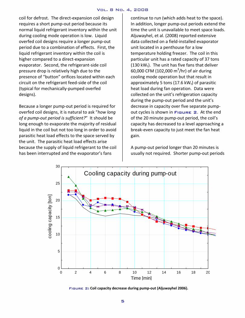
coil for defrost. The direct-expansion coil design requires a short pump-out period because its normal liquid refrigerant inventory within the unit during cooling mode operation is low. Liquid overfed coil designs require a longer pump-out period due to a combination of effects. First, the liquid refrigerant inventory within the coil is higher compared to a direct-expansion evaporator. Second, the refrigerant-side coil pressure drop is relatively high due to the presence of “button” orifices located within each circuit on the refrigerant feed-side of the coil (typical for mechanically-pumped overfed designs). Because a longer pump-out period is required for overfed coil designs, it is natural to ask “how long of a pump-out period is sufficient?” It should be long enough to evaporate the majority of residual liquid in the coil but not too long in order to avoid parasitic heat load effects to the space served by the unit. The parasitic heat load effects arise because the supply of liquid refrigerant to the coil has been interrupted and the evaporator’s fans
Figure 2: Coil capacity decrease during pump-out (Aljuwayhel 2006).
0 2 4 6 8 10 12 14 16 18 200
5
10
15
20
25
30
Time [min]
cool
ing
capa
city
[ton
]
Cooling capacity during pump-out
continue to run (which adds heat to the space). In addition, longer pump-out periods extend the time the unit is unavailable to meet space loads. Aljuwayhel, et al. (2008) reported extensive data collected on a field-installed evaporator unit located in a penthouse for a low temperature holding freezer. The coil in this particular unit has a rated capacity of 37 tons (130 kWt). The unit has five fans that deliver 60,000 CFM (102,000 m3/hr) of air during cooling mode operation but that result in approximately 5 tons (17.6 kWt) of parasitic heat load during fan operation. Data were collected on the unit’s refrigeration capacity during the pump-out period and the unit’s decrease in capacity over five separate pump-out cycles is shown in Figure 2. At the end of the 20 minute pump-out period, the coil’s capacity has decreased to a level approaching a break-even capacity to just meet the fan heat gain. A pump-out period longer than 20 minutes is usually not required. Shorter pump-out periods

Vol. 8 No. 4, 2008
6
should be validated by observing the frost melt pattern on the coil during the hot-gas supply period of the defrost sequence. Assuming the coil is top-fed with hot-gas, an adequate pump-out period is likely established when the bottom rows of the coil completely release their frost during the hot-gas dwell period and when no audible effects of hydraulic hammering are observed on the coil and its connected piping during the early part of the hot-gas supply period. STEP 2: SOFT-GAS
The use of a soft-gas step in the defrost sequence is recommended for coils with capacities of 15 tons (53 kWt) or greater (Briley 2004). The soft-gas period of the defrost sequence begins by cycling off the evaporator fans and actuating the pilot solenoid for the suction stop valve. The pilot solenoid applies hot-gas pressure to the top of the suction stop valve’s piston forcing the valve closed (typically a CK2 or CK5 type valve). With the coil now isolated from the system’s suction pressure, a small ported (e.g. ½”) “soft-gas solenoid valve” is opened to allow a low flow rate of hot-gas into the coil via the drain pan warming circuit; thereby, slowly raising the pressure of refrigerant in the coil. The soft-gas cycle is intended to reduce the risk of hydraulic hammer that can occur on the coil itself or connected piping by reducing the pressure difference between the coil and the hot-gas main. The reduced pressure difference will decrease the rapid in-rush of hot-gas when the larger main hot-gas solenoid opens. Briley (2004) recommends sizing the soft-gas solenoid at 20-25% of the main hot-gas solenoid valve. Figure 3 shows the valve positions and the evaporator fan state during the soft-gas period. In many installations, the soft-gas dwell time is set to last for a period ranging from 2 to 4 minutes.
Figure 3: Valve positions and fan operation during the soft-gas period for a typical liquid overfed coil.
Regulated hot gas
Wet Suction Return
Pumped Liquid Supply
Defrost return (medium pressure)
A4AK
Suction Stop Valve
Recirculated liquid/vapor return
Recirculated liquid supply
Defrost hot gas supply
Defrost reliefregulator
[Closed]
[Open]
[Closed]
Hot Gas Solenoid
[Open]
Soft Gas Solenoid
Liquid Feed Solenoid
Suction Stop Pilot Solenoid
Hand valve
BleedSolenoid
Pilot PressureRegulator
[Closed]
[Closed]
Mode Valve(s) Position
Soft gas
Suction stop valve Closed
Suction stop pilot solenoid Open
Bleed solenoid Closed
Liquid feed solenoid Closed
Soft gas solenoid Open
Hot gas solenoid Closed
[Evaporator fans – off]
Defrost condensate

Vol. 8 No. 4, 2008
7
Soft gas dwell periods up to 20 minutes may be required for larger evaporators or applications having large operating pressure differences between the hot-gas main and the evaporator. The soft-gas dwell period is adjusted to raise the evaporator pressure to approximately 35-40 psig (2.4-2.75 barg) before moving to the next mode in the sequence of defrost operation. It should be noted that not all evaporators have a soft-gas solenoid. While it is beneficial for all evaporators, it is more common on larger capacity evaporators. STEP 3: HOT-GAS Thus far, the individual segments of the defrost sequence have focused on preparing the coil to receive hot-gas in order to melt the accumulated frost. In this portion of the defrost sequence, the larger “hot-gas solenoid” opens to deliver hot-gas first through the coil’s drain pan and then the evaporator coil as shown in Figure 4. During the hot-gas supply period, the smaller soft-gas solenoid can either remain open or close since the majority of gas flow will now occur through the main hot-gas valve.
Figure 4: Valve positions and fan operation during the hot-gas period for a typical liquid overfed coil.
As high-pressure superheated refrigerant vapor flows first through the piping in the drain pan circuit and then into the coil, the high pressure vapor condenses as it gives up its latent heat to warm both the drain pan and the evaporator coil surfaces. A warm drain pan will help prevent re-freezing of the water draining from the coil to the pan. As the coil surfaces warm, the accumulated layer of frost will begin to melt – flowing by gravity down the coil and into the pan before leaving the unit through a drain line. The condensed liquid refrigerant is directed from the coil to a lower pressure
Regulated hot gas
Wet Suction Return
Pumped Liquid Supply
Defrost return (medium pressure)
A4AK
Suction Stop Valve
Recirculated liquid/vapor return
Recirculated liquid supply
Defrost hot gas supply
Defrost reliefregulator
[Closed]
[Open]
[Open]
Hot Gas Solenoid
[Closed]
Soft Gas Solenoid
Liquid Feed Solenoid
Suction Stop Pilot Solenoid
Hand valve
BleedSolenoid
Pilot PressureRegulator
[Closed]
[Closed]
Mode Valve(s) Positio
Hot gas
Suction stop valve Closed
Suction stop pilot solenoid Open
Bleed solenoid Closed
Liquid feed solenoid Closed
Soft gas solenoid Closed
Hot gas solenoid Open
[Evaporator fans – off]
Defrost condensate

Vol. 8 No. 4, 2008
8
level in the plant through a “defrost relief regulating valve.” The defrost relief regulator is factory set at a user-specified pressure – usually 70-90 psig (4.8-6.2 barg) (equivalent to a saturation temperature of 47-58°F [8-14°C] for ammonia). The defrost relief regulator will modulate its position to maintain the evaporator at the regulator’s pressure setting and it will fully reseat at the conclusion of the hot-gas dwell period. A check valve is required on the outlet of the defrost relief regulator when the defrost condensate return is piped to a suction pressure higher than the evaporator’s normal operating pressure. How long should I set the hot-gas supply period? The dwell period of the hot-gas supply needs to be sufficient to allow all the accumulated frost on the coil to melt but not excessive to avoid creating a parasitic heat load both external (to the space) and internal (to the refrigeration system) by returning uncondensed hot-gas back to suction through the defrost relief regulator. Aljuwayhel (2006) collected data on a penthouse-mounted evaporator during both cooling mode and defrost mode of operation. For the evaporator defrost control as-found, the hot-gas dwell period was 40 minutes. Figure 5 shows both model-predicted and field-measured average air temperatures within the penthouse during the hot-gas and subsequent bleed periods of the defrost sequence. In this situation, the coil was completely cleared of accumulated frost in less than 11 minutes during the hot-gas supply; however, the actual hot-gas dwell time lasted for 40 minutes. Within 15 minutes of the main hot-gas valve opening, the average penthouse air temperature reached a balmy 68°F (20°C) and that temperature was maintained for 25 of the 40 minutes which suggests that the continued supply of hot-gas to the coil was not resulting in the full condensing of the refrigerant vapor. Rather, a significant portion of the hot-gas was flowing back to suction and creating a parasitic load (internal) on the compressors. The parasitic effect of excessive hot-gas dwell periods presents an opportunity for improving the system’s energy efficiency by simply modifying the hot-gas dwell period.
Figure 5: Measured and predicted average penthouse air temperatures during hot-gas defrost and bleed periods
(Aljuwayhel 2006).

Vol. 8 No. 4, 2008
9
STEP 4: BLEED At the conclusion of the hot-gas dwell period, a “bleed” or “equalize” sequence is initiated. During the bleed period, the hot-gas solenoid valve (and soft-gas solenoid if open) is closed and a small “bleed solenoid valve” opens to slowly depressurize the coil by relieving the pressure in the coil back to suction. The bleed solenoid valve is typically 3-4 sizes smaller than the main suction stop valve but not less than ½” (Hansen 2006). An optional hand valve in the bleed line can be used to field-adjust the rate of coil depressurization as shown in Figure 6.
Figure 6: Valve positions and fan operation during the bleed period for a typical liquid overfed coil.
A bleed period is necessary, particularly on large coils (with capacities greater than 15 tons [53 kWt]), to prevent what would be a very rapid depressurization of the coil when the suction stop valve opens. Rapid coil depressurization increases the potential for hydraulic hammering to the coil itself and the connected suction piping. The bleed period also prevents rapid swings in suction pressure and compressor loading that would normally result as the engine room responds to maintain a constant suction pressure. The duration of the bleed period is installation-dependent and should be adjusted so no audible hammering occurs and the time is sufficient to decrease the coil pressure to within 10 psid (70 kPa) or less of the normal cooling mode evaporator pressure. Generally, the bleed period will last 5-10 minutes. At the conclusion of the bleed period, the suction stop pilot solenoid is de-energized to allow the main valve to open. As configured in the evaporator schematics, the pilot pressure regulator located in a branch line taken from the suction side of the coil will hold the main suction stop valve for the coil closed until the set pressure of the pilot regulator is reached. This pilot regulator should be set to a pressure difference no greater than 10 psid (70 kPa). The addition of this valve (and other valve designs that provide similar function) is a critical safety measure to avoid hydraulic
Regulated hot gas
Wet Suction Return
Pumped Liquid Supply
Defrost return (medium pressure)
A4AK
Suction Stop Valve
Recirculated liquid/vapor return
Recirculated liquid supply
Defrost hot gas supply
Defrost reliefregulator
[Closed]
[Open]
[Closed]
Hot Gas Solenoid
[Closed]
Soft Gas Solenoid
Liquid Feed Solenoid
Suction Stop Pilot Solenoid
Hand valve
BleedSolenoid
Pilot PressureRegulator
[Closed]
[Open]
Mode Valve(s) Positio
Bleed
Suction stop valve Closed
Suction stop pilot solenoid Open
Bleed solenoid Open
Liquid feed solenoid Closed
Soft gas solenoid Closed
Hot gas solenoid Closed
[Evaporator fans – off]
Defrost condensate

Vol. 8 No. 4, 2008
10
hammer that is likely to occur from a rapid opening of the suction stop valve when the coil is under pressure. It is important to note that if the bleed period is too short, the coil pressure will remain high and the suction stop valve will be held closed for an extended period of time by the pilot pressure regulator bleeding pressure from coil to the top of the suction stop valve’s piston. If the suction stop valve does not open, it becomes impossible to prepare the coil for re-chilling. At first glance, it appears that the small pilot regulator is redundant since the bleed solenoid provides the slow depressurization of the coil to within 10 psid (or less) (70 kPa) of normal evaporator pressure. This is true under normal circumstances; however, the rapid opening of the suction stop valve will occur if the coil is in the hot-gas dwell period and a power outage occurs causing all solenoids to go to their normal positions. In this situation the suction stop pilot solenoid (which is holding the suction stop valve closed by pressurizing the top of the valve’s piston) will close; thereby, allowing the suction stop valve to rapidly open as it returns to its normal position. The net result is an increased likelihood of hydraulic hammering with the risk of failure of the evaporator or connected piping. In the next Cold Front, we will discuss causes of both hydraulic hammer and condensation-induced shock that can lead to catastrophic failures and techniques for their prevention. STEP 4: RE-CHILL With the coil depressurized and the suction stop valve open, it is ready to return to refrigeration mode. In the re-chill mode, the liquid feed solenoid is opened to allow cold liquid refrigerant to flow into the coil. Early in the re-chill period, the cold liquid supply will more rapidly evaporate as it absorbs heat from the coil mass as it reduces the coil temperature. The fans on the unit will usually remain off. Some plants will short-cycle (bump) the fans on and off to allow any remaining water on the external surfaces of the coil to re-freeze while preventing the carryover of liquid water into the space that would normally occur if the fans were allowed to run at their full flow. Figure 7 shows the valve positions during the re-chill period which generally lasts 3-5 minutes. Now that we have discussed the sequences of operation associated with initiating defrost of an air-cooling evaporator, let’s look at the energy consequences of this process. Net Cooling Optimization As we discussed in the last issue of the Cold Front, the accumulation of frost on a coil progressively decreases its cooling capacity; thereby, necessitating a defrost cycle. The defrost cycle itself is a source of efficiency loss to the system but necessary to restore the coil’s capacity by removing the accumulated frost. This fact raises the question: What is the appropriate balance between tolerating the capacity loss for accumulated frost and the parasitic load effects attributable to the defrost cycle? Figure 8 is an illustration of the time-dependent energy flows associated with the operation of a forced air circulation evaporator for both cooling mode and defrost mode operation. The operation of the coil from point a to b is reflective of the diminishing cooling capacity of the unit due to frosting during normal cooling mode operation. At point b the pump-out period begins and the unit’s capacity drops rapidly as the coil is “starved” and the residual refrigerant within the coil is removed by evaporation. Following the pump-out period, the coil’s capacity actually becomes negative (it is heating rather than cooling) as hot-gas is supplied to warm the coil and melt accumulated frost. After the hot-gas flow is terminated (point c), the coil will gradually cool down during re-chill until it reaches the point at which it can begin normal cooling mode operation (point d).

Vol. 8 No. 4, 2008
11
Figure 7: Valve positions and fan operation during the re-chill period for a typical liquid overfed coil.
Figure 8: An illustration of the time-dependent energy flows for cooling mode and defrost mode of operation
(Note: this graphic is not to scale in either capacity or time) (adapted from Aljuwayhel 2006b).
Regulated hot gas
Wet Suction Return
Pumped Liquid Supply
Defrost return (medium pressure)
A4AK
Suction Stop Valve
Recirculated liquid/vapor return
Recirculated liquid supply
Defrost hot gas supply
Defrost reliefregulator
[Open]
[Closed]
[Closed]
Hot Gas Solenoid
[Closed]
Soft Gas Solenoid
Liquid Feed Solenoid
Suction Stop Pilot Solenoid
Hand valve
BleedSolenoid
Pilot PressureRegulator
[Open]
Mode Valve(s) Positio
Re-chill
Suction stop valve Open
Suction stop pilot solenoid Closed
Bleed solenoid Open
Liquid feed solenoid Open
Soft gas solenoid Closed
Hot gas solenoid Closed
[Evaporator fans – Off]
Defrost condensate
[Open]
time
Evap
orat
or c
apac
ity
Coil initial condition (no frost)
Coil capacity decreases as frost continues to form
Coil capacity drops rapidly as refrigerant flow is stoppedand the “pump out” process proceeds preparing the coilfor defrost
Parasitic energy is attributed to warming the coil mass and both sensible and latent losses to the space
Hot gas defrost terminates and coil begins to cool down
Coil transitions from a temperature warmer than the space to a temperature cooler than the space so useful refrigeration is now restored
a
b
c
d

Vol. 8 No. 4, 2008
12
Net cooling optimization aims to maximize the integrated heat removal capability of the evaporator during an entire operational cycle: cooling mode to defrost and back to cooling mode. This integrated heat removal capacity is represented by the blue shaded region in Figure 8. The red hatched area above the operating capacity line represents the integrated cooling deficit below the coil’s rated capacity due to both frost accumulation and the fact that the coil is unavailable during the actual defrost sequence. The red shaded portion of the illustration below the line of zero coil capacity represents the parasitic effects of the coil actually heating the space during the hot-gas dwell period. Aljuwayhel (2006) explored the prospect of optimizing the entire cooling and defrost mode operation – i.e. maximizing the blue shaded portion under the cooling curve shown in Figure 8. Aljuwayhel defined a dimensionless Defrost Number as:
[ ]condensate
min d
VDefrost numberA L
where Vcondensate (ft3) represents the volume of water condensate produced at the conclusion of a defrost cycle, Amin (ft2) represents the minimum area available for air to flow through the coil (coil face area minus the fin face area and the tube projected area) and Ld (ft) represents the depth of the coil in the direction of air flow. Aljuwayhel found that a Defrost number of 0.03 yielded a maximum in net cooling capacity. Figure 9 shows the net cooling optimization results using “Overall system efficiency” as a figure of merit over a range of space latent loads.
Figure 9: Net cooling optimization results (Aljuwayhel 2006).
Aljuwayhel defines the overall system efficiency as the ratio of the actual integrated evaporator coil cooling capacity to the ideal cooling capacity during an entire operational cycle. The ideal cooling capacity is assumed to be equivalent to the coil’s clean capacity maintained during the entire cycle. Aljuwayhel found that the Defrost number was a useful figure of merit because it scales the volume of water condensate a coil produced during defrost to the volume of frost the coil is capable of holding. The finding of net cooling optimization for a Defrost number of 0.03 translates to a coil accumulating

Vol. 8 No. 4, 2008
13
approximately 3% of a representative volume before initiating a defrost sequence. Techniques to field-measure the Defrost number will be discussed in a future edition of the Cold Front. Conclusions In this article, we review the basic sequences of operation for defrosting forced-air cooling evaporators. The most common defrost sequence involves five steps including: pump-out, soft-gas, hot-gas, bleed, and re-chill modes. Some of these steps may be omitted from defrost sequences based on the coil’s refrigerant feed configuration or size. A key consideration in field-tuning defrost sequence time settings is obtaining both a functional defrost but one that does not result in audible hammering of the coil or its connected piping. We also introduced some key features relating to the function of the suction stop valve to prevent its rapid opening when there is greater than a 10 psi (or lower) (70 kPa) pressure difference between the evaporator and suction. There is an opportunity to improve the energy performance of many defrosting evaporators. One of the easiest adjustments to consider for improving the efficiency of the defrost process is the adjustment of the hot-gas dwell period. In general, hot-gas dwell periods in excess of 15 minutes in duration may be candidates for efficiency improvement by decreasing the dwell period. The concept of net cooling optimization is introduced. Net cooling optimization involves maximizing the time-dependent heat extraction capability of an air-cooling evaporator during both cooling and defrost modes. Aljuwayhel found that a Defrost number of 0.3 yielded optimum performance.
References Aljuwayhel, N.F., Reindl, D.T. Klein, S.A., Nellis, G.F., “Experimental investigation of the performance of
industrial evaporator coils operating under frosting conditions”, International Journal of Refrigeration, Volume 31, No. 1, pp. 98-106, (2008).
Aljuwayhel, N.F., “Numerical and Experimental Study of the Influence of Frost Formation and Defrosting on the Performance of Industrial Evaporator Coils”, Ph.D. Thesis, University of Wisconsin-Madison, (2006).
Aljuwayhel, N.F., “Optimizing Air-Cooling Evaporators”, presented at the IRC Research and Technology Forum, Madison, WI, (2006b).
ASHRAE, ASHRAE Handbook - Refrigeration, Chapter 42, American Society of Heating, Refrigerating, and Air conditioning Engineers, Atlanta GA, (2006).
Briley, G. C., “Optimizing Defrost Systems, Part 3”, Process Cooling and Equipment, January (2004).
Hansen Technologies, “Collection of Instructions, Hansen Technologies Corporation, pg. 78, Burr Ridge, IL (2006).


![Industrial Refrigeration Handbook[1]](https://img.pdfslide.us/doc/110x75/54a1447eac7959b5708b46fc/industrial-refrigeration-handbook1.jpg)