Embed Size (px)
Citation preview
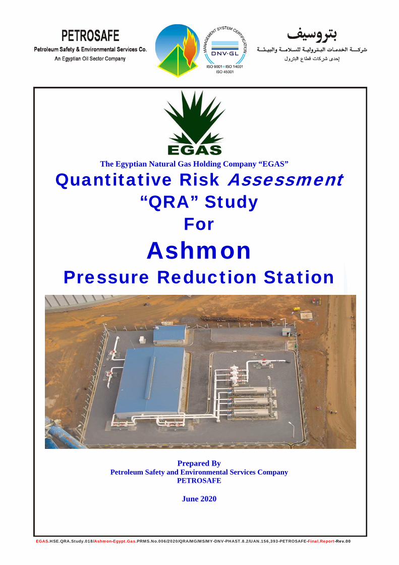
The Egyptian Natural Gas Holding Company “EGAS”
Quantitative Risk Assessment “QRA” Study
For Ashmon
Pressure Reduction Station
Prepared By
Petroleum Safety and Environmental Services Company PETROSAFE
June 2020
EGAS.HSE.QRA.Study.018/Ashmon-Egypt.Gas.PRMS.No.006/2020/QRA/MG/MS/MY-DNV-PHAST.8.2/UAN.156,393-PETROSAFE-Final.Report-Rev.00

Page 1 of 119
Egyptian Natural Gas Holding Company “EGAS”
Prepared By: PETROSAFE
Date: June 2020
Document Title: Quantitative Risk Assessment “QRA” Study For Ashmon Pressure Reduction & Metering Station
EGAS.HSE.QRA.Study.018/Ashmon-Egypt.Gas.PRMS.No.006/2020/QRA/MG/MS/MY-DNV-PHAST.8.2/UAN.156,393-PETROSAFE-Final.Report-Rev.00
Title Quantitative Risk Assessment Study For Ashmon New Pressure Reduction Station – El-Monofia Governorate
Customer Egyptian Natural Gas Holding Company “EGAS” Customer Reference EGAS/QRA/02/2015-MG/MS Confidentiality, Copyright and Reproduction
This document has been prepared by PETROSAFE in connection with a contract to supply services and is submitted only on the basis of strict confidentiality. The contents must not be disclosed to third parties other than in accordance with the terms of the contract.
Report Number EGAS.HSE.QRA.Study.018/Ashmon-Egypt.Gas/PRMS.No.006/2020/QRA/MG/MS/MY-DNV-
PHAST.8.2/UAN.156,393-PETROSAFE-Final.Report-Rev.00 Report Status Revision 00 PETROSAFE
6w/4 Hassan Nassar St. - Takseem El-Laselky - New Maadi, Cairo, Egypt Telephone: +(202) 2517 6935 / 2517 6936 / 2517 6937 Facsimile: +(202) 2517 6938 / 2517 6958 e-mail: [email protected]
[email protected] / [email protected] Name Signature Date Team Work Eng. Mohamad Yousry
PETROSAFE /06/2020 Loss Prevention Specialist Chem. Mohamad Samy PETROSAFE /06/2020 Safety Affairs Asst. Gen. Mgr. Geo. Mohamad Al-Ghazaly PETROSAFE /06/2020 Saf. & Env. Affairs Gen. Mgr. Reviewed by Dr. Emad Kelany
EGAS /06/2020 Safety Asst. Gen. Mgr. Eng. Ahmad Farag EGAS /06/2020 World Bank Project Gen. Mgr. Approved by Sameh Abd Al Razek
EGAS /06/2020 Asst. Chairman for Health & Safety
Eng. Ahmed Mahmoud EGAS /06/2020 Vice Chairman for Planning &
Gas Projects Distribution • Client: EGAS • File: EGAS / PETROSAFE • Library: EGAS / PETROSAFE

Page 2 of 119
Egyptian Natural Gas Holding Company “EGAS”
Prepared By: PETROSAFE
Date: June 2020
Document Title: Quantitative Risk Assessment “QRA” Study For Ashmon Pressure Reduction & Metering Station
EGAS.HSE.QRA.Study.018/Ashmon-Egypt.Gas.PRMS.No.006/2020/QRA/MG/MS/MY-DNV-PHAST.8.2/UAN.156,393-PETROSAFE-Final.Report-Rev.00
CONTENTS
Executive Summary 08/119 Introduction 18/119 Technical Definitions 19/119 Objectives 24/119 Quantitative Risk Assessment Study Scope 25/119 Quantitative Risk Assessment “QRA” Studies 26/119 Method of Assessment 26/119 1.0- General Method Used 26/119 2.0- Risk Assessment 26/119 Modeling the Consequences 28/119 Criterion for Risk Tolerability 29/119 Personnel Vulnerability and Structural Damage 32/119 Quantification of the Frequency of Occurrence 35/119 Identification of Scenarios Leading to Selected Failures 35/119 Relevant Weather Data for the Study 36/119
- Weather Data 36/119 - Stability Categories 40/119
Ashmon PRMS Description 41/119 Background 41/119 The PRMS & Off-Take Location Coordinates 41/119 PRMS Brief Description and Components 41/119 Ashmon PRMS Units 42/119 Process Condition Data 50/119
Gas Odorant Specifications 51/119
Health Hazards 51/119
Inhalation 51/119
Skin Contact 51/119
Page 3 of 119
Egyptian Natural Gas Holding Company “EGAS”
Prepared By: PETROSAFE
Date: June 2020
Document Title: Quantitative Risk Assessment “QRA” Study For Ashmon Pressure Reduction & Metering Station
EGAS.HSE.QRA.Study.018/Ashmon-Egypt.Gas.PRMS.No.006/2020/QRA/MG/MS/MY-DNV-PHAST.8.2/UAN.156,393-PETROSAFE-Final.Report-Rev.00
Eye Contact 51/119
Ingestion 51/119
Hygiene Standards and Limits 51/119
Fire and Explosion Hazards 51/119
Fire Fighting and Protection Systems and Facilities 52/119
Emergency Response Plan “ERP” 52/119
Analytical Results of Consequence Modeling 53/119
1.0- Pressure Reduction Station Inlet Pipeline (4 inch) 53/119
1/1- Consequence Modeling for 1 inch (Pin Hole) Gas Release 53/119
1/2- Consequence Modeling for 2 inch (Half Rup.) Gas Release 56/119
1/3- Consequence Modeling for 4 inch (Full Rup.) Gas Release 60/119
2.0- Pressure Reduction Station Outlet Pipeline (6 inch) 64/119
2/1- Consequence Modeling for 1 inch (Pin Hole) Gas Release 64/119
2/2- Consequence Modeling for 3 inch (Half Rup.) Gas Release 67/119
2/3- Consequence Modeling for 6 inch (Full Rup.) Gas Release 71/119
3.0- Pressure Reduction Station Odorant Tank (Spotleak) 76/119
4.0- Gas Heater (Water Bath Heating System) 83/119
5.0- Pressure Reduction Station Off-take Pipeline (4 inch) 89/119
5/1- Consequence Modeling for 1 inch (Pin Hole) Gas Release 89/119
5/2- Consequence Modeling for 2 inch (Half Rup.) Gas Release 92/119
5/3- Consequence Modeling for 4 inch (Full Rup.) Gas Release 95/119
Individual Risk Evaluation 98/119
• Risk Calculation 98/119
• Event Tree Analysis 101/119
Summary of Modeling Results and Conclusion 112/119
Recommendations 118/119

Page 4 of 119
Egyptian Natural Gas Holding Company “EGAS”
Prepared By: PETROSAFE
Date: June 2020
Document Title: Quantitative Risk Assessment “QRA” Study For Ashmon Pressure Reduction & Metering Station
EGAS.HSE.QRA.Study.018/Ashmon-Egypt.Gas.PRMS.No.006/2020/QRA/MG/MS/MY-DNV-PHAST.8.2/UAN.156,393-PETROSAFE-Final.Report-Rev.00
Tables Table (1) Description of Modeling of the Different Scenario 28/119 Table (2) Proposed Individual Risk (IR) Criteria (per person/year) 30/119 Table (3) Criteria for Personnel Vulnerability & Structural Damage 32/119 Table (4) Heat Radiation Effects on Structures (World Bank) 33/119 Table (5) Heat Radiation Effects on People 33/119 Table (6) Effects of Overpressure 34/119
Table (7) Annual Average Temperature, Relative Humidity and Wind Speed / Direction 36/119
Table (8) Mean of Monthly Air Temperature (°C) 37/119 Table (9) Mean of Monthly Wind Speed (m/sec) 37/119 Table (10) Mean of Monthly Average Relative Humidity 37/119 Table (11) Pasqual Stability Categories 40/119 Table (12) Relationship between Wind Speed and Stability 40/119 Table (13) Sets of Weather Conditions Initially Selected for this Study 40/119 Table (14) Ashmon PRMS Units 42/119 Table (15) Process Conditions / Gas Components & Specifications 50/119 Table (16) Dispersion Modeling for Inlet – 1” / 4” Gas release 53/119 Table (17) Dispersion Modeling for Inlet – 2” / 4” Gas release 56/119 Table (18) Dispersion Modeling for Inlet – 4” Gas release 60/119 Table (19) Dispersion Modeling for Outlet – 1” / 6” Gas release 64/119 Table (20) Dispersion Modeling for Outlet – 3” / 6” Gas release 67/119 Table (21) Dispersion Modeling for Outlet – 6” Gas release 71/119 Table (22) Dispersion Modeling for Odorant Tank (Spotleak) 76/119 Table (23) Dispersion Modeling for Heater Tank 83/119 Table (24) Dispersion Modeling for Off-take – 1” / 4” Gas release 89/119 Table (25) Dispersion Modeling for Off-take – 2” / 4” Gas release 92/119 Table (26) Dispersion Modeling for Off-take – 4” Gas release 95/119 Table (27) Failure Frequency for Each Scenario 100/119
Table (28) Inlet 4” / Outlet 6” / Off-Take 4” / Pipeline & Gas Heater Scenarios (Pin Hole Crack – 1” Release) – ETA 103/119
Page 5 of 119
Egyptian Natural Gas Holding Company “EGAS”
Prepared By: PETROSAFE
Date: June 2020
Document Title: Quantitative Risk Assessment “QRA” Study For Ashmon Pressure Reduction & Metering Station
EGAS.HSE.QRA.Study.018/Ashmon-Egypt.Gas.PRMS.No.006/2020/QRA/MG/MS/MY-DNV-PHAST.8.2/UAN.156,393-PETROSAFE-Final.Report-Rev.00
Table (29) Inlet 4” / Outlet 6” / Off-Take 4” Pipeline Scenarios (Half Rupture Release) – ETA 104/119
Table (30) Off-Take 4” / Inlet 4” / Outlet 6” Pipeline Scenarios (Full Rupture Release) – ETA 105/119
Table (31) Odorant Tank Release – ETA 106/119 Table (32) Total Frequencies for Each Scenario 107/119 Table (33) Summarize the Risk on Workers / Public Exposure 107/119 Table (34) Individual Risk (IR) Calculation for PRMS Workers 109/119
Table (35) Individual Risk (IR) Calculation for the Public Near to the PRMS 110/119
Figures Figure (1) Risk Assessment Framework 27/119 Figure (2) Criteria for Individual Risk Tolerability 29/119 Figure (3) Proposed Individual Risk Criteria 30/119
Figure (4) Monthly Variations of the Maximum Temperature for Ashmon Area 37/119
Figure (5) Monthly Variations of the Wind Speed for Ashmon Area 38/119 Figure (6) Wind Rose for Ashmon Area 38/119
Figure (7) Monthly Variations of the Sunny, Cloudy and Precipitation days for Ashmon Area 39/119
Figure (8) Ashmon Pressure Reduction and Metering Station “PRMS” General Layout (Egypt Gas Data) 44/119
Figure (9) Ashmon PRMS Piping and Instrumentation Diagram “P&ID” for Inlet & Filter Separator Section 45/119
Figure (10) Ashmon PRMS Piping and Instrumentation Diagram “P&ID” for Odorant System Section 46/119
Figure (11) Ashmon PRMS Piping and Instrumentation Diagram “P&ID” for Meter, Regulator and Outlet Section 47/119
Figure (12) Ashmon PRMS and Surroundings Plotted on Google Earth Photo 48/119
Figure (13) Ashmon Offtake and Surroundings Plotted on Google Earth Photo 49/119
Page 6 of 119
Egyptian Natural Gas Holding Company “EGAS”
Prepared By: PETROSAFE
Date: June 2020
Document Title: Quantitative Risk Assessment “QRA” Study For Ashmon Pressure Reduction & Metering Station
EGAS.HSE.QRA.Study.018/Ashmon-Egypt.Gas.PRMS.No.006/2020/QRA/MG/MS/MY-DNV-PHAST.8.2/UAN.156,393-PETROSAFE-Final.Report-Rev.00
Figure (14) Gas Cloud Side View (UFL/LFL) (1” hole in 4” Inlet Pipeline) 54/119
Figure (15) Heat Radiation Contours from Jet Fire (1” hole in 4” Inlet Pipeline) 55/119
Figure (16) Gas Cloud Side View (UFL/LFL) (2” hole in 4” Inlet Pipeline) 57/119
Figure (17) Heat Radiation Contours from Jet Fire (2” hole in 4” Inlet Pipeline) 58/119
Figure (18) Late Explosion Overpressure Waves (2” hole in 4” Inlet Pipeline) 59/119
Figure (19) Gas Cloud Side View (UFL/LFL) (4” Inlet Pipeline Full Rupture) 61/119
Figure (20) Heat Radiation Contours from Jet Fire (4” Inlet Pipeline Full Rupture) 62/119
Figure (21) Late Explosion Overpressure Waves (4” Inlet Pipeline Full Rupture) 63/119
Figure (22) Gas Cloud Side View (UFL/LFL) (1” hole in 6” Outlet Pipeline) 65/119
Figure (23) Heat Radiation Contours from Jet Fire (1” hole in 6” Outlet Pipeline) 66/119
Figure (24) Gas Cloud Side View (UFL/LFL) (3” hole in 6” Outlet Pipeline) 68/119
Figure (25) Heat Radiation Contours from Jet Fire (3” hole in 6” Outlet Pipeline) 69/119
Figure (26) Late Explosion Overpressure Waves (3” hole in 6” Outlet Pipeline) 70/119
Figure (27) Gas Cloud Side View (UFL/LFL) (6” Outlet Pipeline Full Rupture) 72/119
Figure (28) Heat Radiation Contours from Jet Fire (6” Outlet Pipeline Full Rupture) 73/119
Figure (29) Late Explosion Overpressure Waves (6” Outlet Pipeline Full Rupture) 74/119
Figure (30) Heat Radiation Contours from Fireball (6” Outlet Pipeline Full Rupture) 75/119
Figure (31) Vapor Cloud (UFL/LFL) Side View Graph (Odorant leak) 77/119

Page 7 of 119
Egyptian Natural Gas Holding Company “EGAS”
Prepared By: PETROSAFE
Date: June 2020
Document Title: Quantitative Risk Assessment “QRA” Study For Ashmon Pressure Reduction & Metering Station
EGAS.HSE.QRA.Study.018/Ashmon-Egypt.Gas.PRMS.No.006/2020/QRA/MG/MS/MY-DNV-PHAST.8.2/UAN.156,393-PETROSAFE-Final.Report-Rev.00
Figure (32) Cloud Footprint (UFL/LFL) on site (Odorant leak) 77/119
Figure (33) Heat Radiation Contours - Jet Fire Graph (Odorant Leak) 79/119
Figure (34) Heat Radiation Contours - Jet Fire on Site (Odorant Leak)
Figure (35) Late Explosion Overpressure Waves Graph (Odorant Leak) 81/119
Figure (36) Late Explosion Overpressure Waves on Site (Odorant Leak)
Figure (37) Vapor Cloud (UFL/LFL) Side View Graph (Gas Heater) 84/119
Figure (38) Heat Radiation Contours - Fire Graph (Gas Heater) 85/119
Figure (39) Heat Radiation Contours - Fire on Site (Gas Heater)
Figure (40) Late Explosion Overpressure Waves Graph (Gas Heater) 87/119
Figure (41) Late Explosion Overpressure Waves on Site (Gas Heater)
Figure (42) Gas Cloud Side View (UFL/LFL) (1” hole in 4” Off-take Pipeline) 90/119
Figure (43) Heat Radiation Contours from Jet Fire (1” hole in 4” Off-take Pipeline) 90/119
Figure (44) Gas Cloud Side View (UFL/LFL) (2” hole in 4” Off-take Pipeline) 93/119
Figure (45) Heat Radiation Contours from Jet Fire (2” hole in 4” off-take Pipeline) 94/119
Figure (46) Gas Cloud Side View (UFL/LFL) (4” off-take Pipeline Full Rupture) 96/119
Figure (47) Heat Radiation Contours from Jet Fire (4” off-take Pipeline Full Rupture) 97/119
Figure (48) Evaluation of Individual Risk 111/119
Page 8 of 119
Egyptian Natural Gas Holding Company “EGAS”
Prepared By: PETROSAFE
Date: June 2020
Document Title: Quantitative Risk Assessment “QRA” Study For Ashmon Pressure Reduction & Metering Station
EGAS.HSE.QRA.Study.018/Ashmon-Egypt.Gas.PRMS.No.006/2020/QRA/MG/MS/MY-DNV-PHAST.8.2/UAN.156,393-PETROSAFE-Final.Report-Rev.00
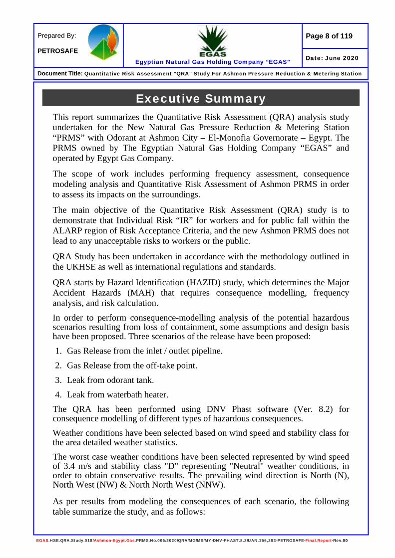
Executive Summary This report summarizes the Quantitative Risk Assessment (QRA) analysis study undertaken for the New Natural Gas Pressure Reduction & Metering Station “PRMS” with Odorant at Ashmon City – El-Monofia Governorate – Egypt. The PRMS owned by The Egyptian Natural Gas Holding Company “EGAS” and operated by Egypt Gas Company.
The scope of work includes performing frequency assessment, consequence modeling analysis and Quantitative Risk Assessment of Ashmon PRMS in order to assess its impacts on the surroundings.
The main objective of the Quantitative Risk Assessment (QRA) study is to demonstrate that Individual Risk “IR” for workers and for public fall within the ALARP region of Risk Acceptance Criteria, and the new Ashmon PRMS does not lead to any unacceptable risks to workers or the public.
QRA Study has been undertaken in accordance with the methodology outlined in the UKHSE as well as international regulations and standards.
QRA starts by Hazard Identification (HAZID) study, which determines the Major Accident Hazards (MAH) that requires consequence modelling, frequency analysis, and risk calculation. In order to perform consequence-modelling analysis of the potential hazardous scenarios resulting from loss of containment, some assumptions and design basis have been proposed. Three scenarios of the release have been proposed: 1. Gas Release from the inlet / outlet pipeline. 2. Gas Release from the off-take point. 3. Leak from odorant tank. 4. Leak from waterbath heater.
The QRA has been performed using DNV Phast software (Ver. 8.2) for consequence modelling of different types of hazardous consequences. Weather conditions have been selected based on wind speed and stability class for the area detailed weather statistics. The worst case weather conditions have been selected represented by wind speed of 3.4 m/s and stability class "D" representing "Neutral" weather conditions, in order to obtain conservative results. The prevailing wind direction is North (N), North West (NW) & North North West (NNW).
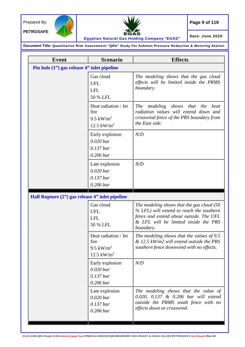
As per results from modeling the consequences of each scenario, the following table summarize the study, and as follows:
Page 9 of 119
Egyptian Natural Gas Holding Company “EGAS”
Prepared By: PETROSAFE
Date: June 2020
Document Title: Quantitative Risk Assessment “QRA” Study For Ashmon Pressure Reduction & Metering Station
EGAS.HSE.QRA.Study.018/Ashmon-Egypt.Gas.PRMS.No.006/2020/QRA/MG/MS/MY-DNV-PHAST.8.2/UAN.156,393-PETROSAFE-Final.Report-Rev.00
Event Scenario Effects Pin hole (1”) gas release 4” inlet pipeline
Gas cloud UFL LFL 50 % LFL
The modeling shows that the gas cloud effects will be limited inside the PRMS boundary.
Heat radiation / Jet fire 9.5 kW/m2
12.5 kW/m2
The modeling shows that the heat radiation values will extend down and crosswind fence of the PRS boundary from the East side.
Early explosion 0.020 bar 0.137 bar 0.206 bar
N/D
Late explosion 0.020 bar 0.137 bar 0.206 bar
N/D
Half Rupture (2”) gas release 4” inlet pipeline Gas cloud
UFL LFL 50 % LFL
The modeling shows that the gas cloud (50 % LFL) will extend to reach the southern fence and extend about outside. The UFL & LFL will be limited inside the PRS boundary.
Heat radiation / Jet fire 9.5 kW/m2
12.5 kW/m2
The modeling shows that the values of 9.5 & 12.5 kW/m2 will extend outside the PRS southern fence downwind with no effects.
Early explosion 0.020 bar 0.137 bar 0.206 bar
N/D
Late explosion 0.020 bar 0.137 bar 0.206 bar
The modeling shows that the value of 0.020, 0.137 & 0.206 bar will extend outside the PRMS south fence with no effects down or crosswind.
Page 10 of 119
Egyptian Natural Gas Holding Company “EGAS”
Prepared By: PETROSAFE
Date: June 2020
Document Title: Quantitative Risk Assessment “QRA” Study For Ashmon Pressure Reduction & Metering Station
EGAS.HSE.QRA.Study.018/Ashmon-Egypt.Gas.PRMS.No.006/2020/QRA/MG/MS/MY-DNV-PHAST.8.2/UAN.156,393-PETROSAFE-Final.Report-Rev.00
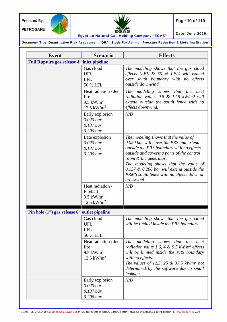
Event Scenario Effects Full Rupture gas release 4” inlet pipeline Gas cloud
UFL LFL 50 % LFL
The modeling shows that the gas cloud effects (LFL & 50 % LFL) will extend over south boundary with no effects outside downwind.
Heat radiation / Jet fire 9.5 kW/m2
12.5 kW/m2
The modeling shows that the heat radiation values 9.5 & 12.5 kW/m2 will extend outside the south fence with no effects downwind.
Early explosion 0.020 bar 0.137 bar 0.206 bar
N/D
Late explosion 0.020 bar 0.137 bar 0.206 bar
The modeling shows that the value of 0.020 bar will cover the PRS and extend outside the PRS boundary with no effects outside and covering parts of the control room & the generator. The modeling shows that the value of 0.137 & 0.206 bar will extend outside the PRMS south fence with no effects down or crosswind.
Heat radiation / Fireball 9.5 kW/m2
12.5 kW/m2
N/D
Pin hole (1”) gas release 6” outlet pipeline Gas cloud
UFL LFL 50 % LFL
The modeling shows that the gas cloud will be limited inside the PRS boundary.
Heat radiation / Jet fire 9.5 kW/m2
12.5 kW/m2
The modeling shows that the heat radiation value 1.6, 4 & 9.5 kW/m2 effects will be limited inside the PRS boundary with no effects. The values of 12.5, 25 & 37.5 kW/m2 not determined by the software due to small leakage.
Early explosion 0.020 bar 0.137 bar 0.206 bar
N/D

Page 11 of 119
Egyptian Natural Gas Holding Company “EGAS”
Prepared By: PETROSAFE
Date: June 2020
Document Title: Quantitative Risk Assessment “QRA” Study For Ashmon Pressure Reduction & Metering Station
EGAS.HSE.QRA.Study.018/Ashmon-Egypt.Gas.PRMS.No.006/2020/QRA/MG/MS/MY-DNV-PHAST.8.2/UAN.156,393-PETROSAFE-Final.Report-Rev.00
Event Scenario Effects Late explosion
0.020 bar 0.137 bar 0.206 bar
N/D
Half Rupture (3”) gas release 6” outlet pipeline Gas cloud
UFL LFL 50 % LFL
The modeling shows that the gas cloud (UFL & LFL) will be limited inside the PRS boundary. While the 50% LFL will extend outside the PRS fence from the south side with no effects downwind.
Heat radiation / Jet fire 9.5 kW/m2
12.5 kW/m2
The modeling shows that the heat radiation values of 9.5, 12.5, 25 & 37.5 kW/m2 will extend outside the PRS boundary south side with no effects downwind.
Early explosion 0.020 bar 0.137 bar 0.206 bar
N/D
Late explosion 0.020 bar 0.137 bar 0.206 bar
The modeling shows that the value of 0.020 bar will cover the PRS and extend outside the PRS boundary with no effects outside and covering parts of the control room & the generator. The values of 0.137 & 0.206 bar will be extended outside the PRS boundary with no effect down or crosswind.
Full Rupture gas release 6” outlet pipeline Gas cloud
UFL LFL 50 % LFL
The modeling shows that the gas cloud effects will be limited inside the PRS boundary.
Heat radiation / Jet fire 9.5 kW/m2
12.5 kW/m2
The modeling shows that the heat radiation values 9.5, 12.5, 25 & 37.5 kW/m2 will extend outside the south fence with no effects down and crosswind.
Early explosion 0.020 bar 0.137 bar 0.206 bar
N/D

Page 12 of 119
Egyptian Natural Gas Holding Company “EGAS”
Prepared By: PETROSAFE
Date: June 2020
Document Title: Quantitative Risk Assessment “QRA” Study For Ashmon Pressure Reduction & Metering Station
EGAS.HSE.QRA.Study.018/Ashmon-Egypt.Gas.PRMS.No.006/2020/QRA/MG/MS/MY-DNV-PHAST.8.2/UAN.156,393-PETROSAFE-Final.Report-Rev.00
Event Scenario Effects Late explosion
0.020 bar 0.137 bar 0.206 bar
The modeling shows that the value of 0.020 bar will cover the PRS and extend outside the PRS boundary with no effects outside and covering the control room and the generator. The values of 0.137 & 0.206 bar will be extended outside the PRS boundary with no effect down or crosswind.
Heat radiation / Fireball 9.5 kW/m2
12.5 kW/m2
The modeling shows that the heat radiation values of 4, 12.5 & 37.5 kW/m2 will limited inside the PRS boundary affecting the PRS facilities with some extension (4 kW/m2) down and crosswind to reach parts of the control room.
Odorant tank 1” leak Gas cloud
UFL LFL 50 % LFL
The modeling shows that the vapor cloud will extend outside the PRS fence from the south side with no effects downwind. Consideration should be taken when deal with liquid, vapors and smokes according to the MSDS for the material.
Heat radiation / Jet fire 9.5 kW/m2
12.5 kW/m2
The modeling shows that all values of heat radiation 9.5, 12.5, 25 & 37.5 kW/m2 will be limited inside the PRS boundary down and crosswind.
Early explosion 0.020 bar 0.137 bar 0.206 bar
N/D
Late explosion 0.020 bar 0.137 bar 0.206 bar
The modeling shows that the value of 0.020 bar will cover the PRS and extend outside the PRS boundary with no effects outside and covering the control room and the generator. The values of 0.137 & 0.206 bar will be extended outside the PRS boundary with no effect down or crosswind.
Gas heater (water bath heating system) Gas cloud
UFL LFL 50 % LFL
The modeling shows that the vapor cloud will extend inside the PRS boundary downwind.
Heat radiation / Jet fire 9.5 kW/m2
The modeling shows that the heat radiation value 1.6, 4, 9.5 & 12.5 kW/m2 effects will be limited inside the PRS

Page 13 of 119
Egyptian Natural Gas Holding Company “EGAS”
Prepared By: PETROSAFE
Date: June 2020
Document Title: Quantitative Risk Assessment “QRA” Study For Ashmon Pressure Reduction & Metering Station
EGAS.HSE.QRA.Study.018/Ashmon-Egypt.Gas.PRMS.No.006/2020/QRA/MG/MS/MY-DNV-PHAST.8.2/UAN.156,393-PETROSAFE-Final.Report-Rev.00
Event Scenario Effects 12.5 kW/m2 boundary with no effects.
The values of 25 & 37.5 kW/m2 not determined by the software due to small leakage.
Early explosion 0.020 bar 0.137 bar 0.206 bar
N/D
Late explosion 0.020 bar 0.137 bar 0.206 bar
The modeling shows that the value of 0.020 bar will extend outside the PRS fence from the east side with no effects outside. The value of 0.137 & 0.206 bar will be limited inside the PRS boundary and reach parts of the PRS components.
Pin hole (1”) gas release 4” off-take pipeline Gas cloud
UFL LFL 50 % LFL
The modeling shows that the gas cloud effects will be limited inside the offtake boundary.
Heat radiation / Jet fire 9.5 kW/m2
12.5 kW/m2
The modeling shows that the heat radiation value of 1.6 kW/m2 will be limited inside the offtake boundary, while the 4 kW/m2 will cover the offtake boundary and extends outside it with no effects. The values of 9.5, 12.5, 25 & 37.5 kW/m2 not determined by the software as they are very small values.
Early explosion 0.020 bar 0.137 bar 0.206 bar
N/D
Late explosion 0.020 bar 0.137 bar 0.206 bar
N/D
Half Rupture (2”) gas release 4” off-take pipeline Gas cloud
UFL LFL 50 % LFL
The modeling shows that the gas cloud effects will be limited inside the Offtake boundary.

Page 14 of 119
Egyptian Natural Gas Holding Company “EGAS”
Prepared By: PETROSAFE
Date: June 2020
Document Title: Quantitative Risk Assessment “QRA” Study For Ashmon Pressure Reduction & Metering Station
EGAS.HSE.QRA.Study.018/Ashmon-Egypt.Gas.PRMS.No.006/2020/QRA/MG/MS/MY-DNV-PHAST.8.2/UAN.156,393-PETROSAFE-Final.Report-Rev.00
Event Scenario Effects Heat radiation / Jet
fire 9.5 kW/m2
12.5 kW/m2
The modeling shows that the heat radiation values of 1.6 & 4 kW/m2 will cover the offtake boundary and extend outside it with no effects. The values of 9.5, 12.5, 25 & 37.5 kW/m2 not determined by the software as they are very small values.
Early explosion 0.020 bar 0.137 bar 0.206 bar
N/D
Late explosion 0.020 bar 0.137 bar 0.206 bar
N/D
Full Rupture gas release 4” off-take pipeline Gas cloud
UFL LFL 50 % LFL
The modeling shows that the gas cloud will be limited inside the Offtake boundary with some extension outside from south side downwind.
Heat radiation / Jet fire 9.5 kW/m2
12.5 kW/m2
The modeling shows that the heat radiation values of 1.6 & 4 kW/m2 will cover the offtake boundary and extend outside it with no effects. The values of 9.5, 12.5, 25 & 37.5 kW/m2 not determined by the software as they are very small values.
Early explosion 0.020 bar 0.137 bar 0.206 bar
N/D
Late explosion 0.020 bar 0.137 bar 0.206 bar
N/D
Heat radiation / Fireball 9.5 kW/m2
12.5 kW/m2
N/D
The previous table shows that there are no direct effects on PRMS workers or surrounding public, so it will be assumed that one person (as public) works as farmer for 1 hour / day light, And one operator (as worker) for operation / maintenance inside the PRS boundary for 2 hours / day light. The major hazards that extend over site boundary and/or effect on workers / public were used for Risk Calculations.

Page 15 of 119
Egyptian Natural Gas Holding Company “EGAS”
Prepared By: PETROSAFE
Date: June 2020
Document Title: Quantitative Risk Assessment “QRA” Study For Ashmon Pressure Reduction & Metering Station
EGAS.HSE.QRA.Study.018/Ashmon-Egypt.Gas.PRMS.No.006/2020/QRA/MG/MS/MY-DNV-PHAST.8.2/UAN.156,393-PETROSAFE-Final.Report-Rev.00
Event Tree Analysis (ETA) is an analysis technique for identifying and evaluating the sequence of events in a potential accident scenario following the occurrence of an initiating event. ETA utilizes a visual logic tree structure known as an event tree (ET). ETA provides a Probabilistic Risk Assessment (PRA) of the risk associated with each potential outcome. ETA has been used for scenario development. The following data and assumptions have been considered in the Event tree analysis (ETA): • Failure frequency data (mainly E&P Forum/OGP), • Risk reduction factors (if available), • Ignition probabilities (both immediate and delayed), • Vulnerability data.
Risks have been assessed for workers / public using International Risk Management Guidelines as a reference. The resulting risks have been compared with International Risk Acceptance Criteria. Risk evaluation for Individual Risk “IR” for the major hazards presented in the following tables:
Individual Risk (IR) Calculation for PRMS Workers
Scenario Event People Individual Risk “IR”
Acceptability Criteria
Gas Release from 1”/ 3” Gas Heater Jet Fire Outdoor
8.23E-07
Acceptable (√)
Gas Release from 1”/ 3” Gas Heater Explosion Outdoor 3.53E-07 Acceptable (√)
Gas Release from 6” outlet pipeline Jet Fire Outdoor 3.61E-08 Acceptable (√)
Odorant tank 1” leak Jet Fire Outdoor 6.89E-07 Acceptable (√)
TOTAL Risk for Worker 1.90E-06 Acceptable (√)

Page 16 of 119
Egyptian Natural Gas Holding Company “EGAS”
Prepared By: PETROSAFE
Date: June 2020
Document Title: Quantitative Risk Assessment “QRA” Study For Ashmon Pressure Reduction & Metering Station
EGAS.HSE.QRA.Study.018/Ashmon-Egypt.Gas.PRMS.No.006/2020/QRA/MG/MS/MY-DNV-PHAST.8.2/UAN.156,393-PETROSAFE-Final.Report-Rev.00
Individual Risk (IR) Calculation for the Public Near to the PRMS
Scenario Event People Individual Risk “IR”
Acceptability Criteria
Gas Release from 3”/6” outlet pipeline
Jet Fire Outdoor
4.12E-07
Acceptable (√)
Gas Release from 4” inlet pipeline
Jet Fire Outdoor 1.81E-08 Acceptable (√) Gas Release from 6” outlet pipeline
Gas Release from 2”/4” inlet pipeline
Explosion Outdoor 1.76E-07 Acceptable (√) Gas Release from 3”/6” outlet pipeline Gas Release from 4” inlet pipeline
Explosion Outdoor 7.74E-09 Acceptable (√) Gas Release from 6” outlet pipeline
Odorant tank 1” leak Explosion Outdoor 1.48E-07 Acceptable (√)
TOTAL Risk for Worker 7.61E-07 Acceptable (√)
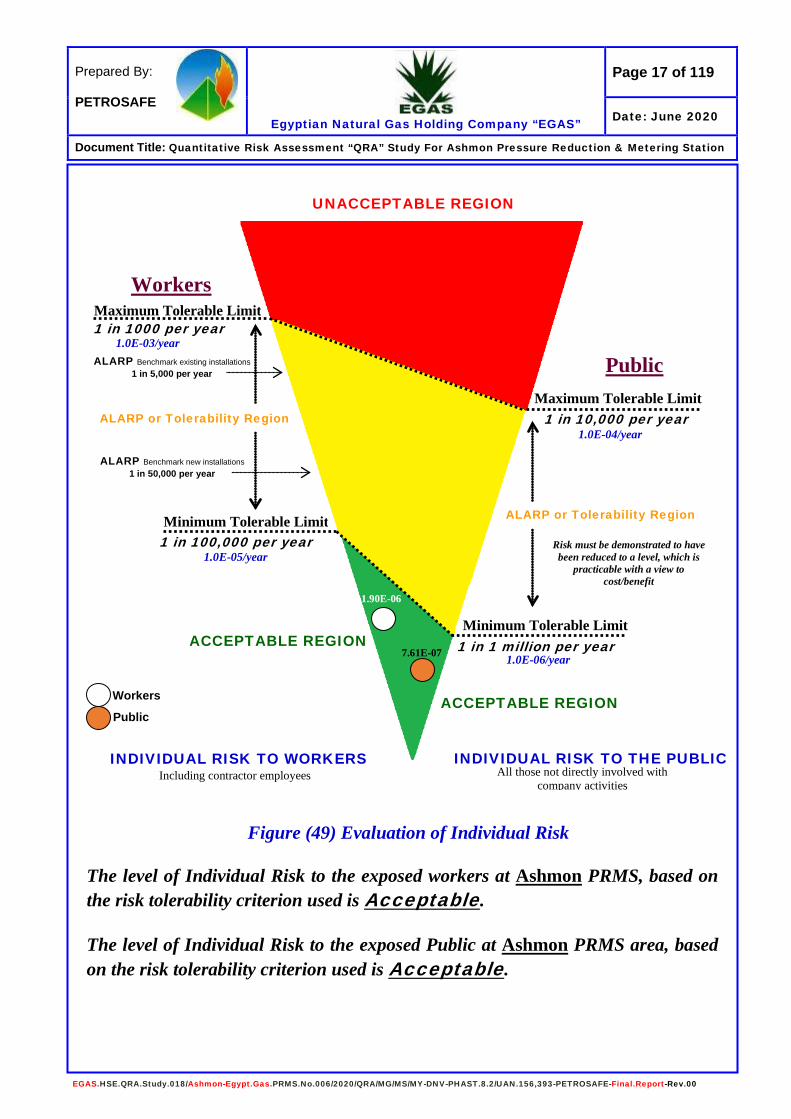
The previous table shows that there is some of direct effects on PRMS workers, and as there is no direct effects on public around the PRMS or the off-take point. Therefore, it will be assumed that one person (as public) works as farmer for 1 hour / day light, And one operator (as worker) for operation / maintenance inside the PRS boundary for 2 hours / day light. (Refer to table 33). Regarding to the results from risk calculations; the risk to PRMS Workers and Public found in Acceptable Region, so there are some points need to be considered to keep the risk tolerability and this will be described in the following recommendations. The following figure shows the Individual Risk “IR” for Ashmon PRMS and Off-Take point:
Page 17 of 119
Egyptian Natural Gas Holding Company “EGAS”
Prepared By: PETROSAFE
Date: June 2020
Document Title: Quantitative Risk Assessment “QRA” Study For Ashmon Pressure Reduction & Metering Station
EGAS.HSE.QRA.Study.018/Ashmon-Egypt.Gas.PRMS.No.006/2020/QRA/MG/MS/MY-DNV-PHAST.8.2/UAN.156,393-PETROSAFE-Final.Report-Rev.00
Figure (49) Evaluation of Individual Risk The level of Individual Risk to the exposed workers at Ashmon PRMS, based on the risk tolerability criterion used is Acceptable. The level of Individual Risk to the exposed Public at Ashmon PRMS area, based on the risk tolerability criterion used is Acceptable.
1.90E-06
Maximum Tolerable Limit
Minimum Tolerable Limit
Workers
1 in 1000 per year
ALARP or Tolerability Region
Minimum Tolerable Limit
Maximum Tolerable Limit
1 in 100,000 per year
1 in 10,000 per year
1 in 1 million per year
Public
Risk must be demonstrated to have been reduced to a level, which is
practicable with a view to cost/benefit
ACCEPTABLE REGION
ACCEPTABLE REGION
ALARP or Tolerability Region
INDIVIDUAL RISK TO THE PUBLIC All those not directly involved with
company activities
INDIVIDUAL RISK TO WORKERS Including contractor employees
UNACCEPTABLE REGION
ALARP Benchmark existing installations 1 in 5,000 per year
ALARP Benchmark new installations 1 in 50,000 per year
1.0E-03/year
1.0E-05/year
1.0E-04/year
1.0E-06/year
Workers
Public
7.61E-07

Page 18 of 119
Egyptian Natural Gas Holding Company “EGAS”
Prepared By: PETROSAFE
Date: June 2020
Document Title: Quantitative Risk Assessment “QRA” Study For Ashmon Pressure Reduction & Metering Station
EGAS.HSE.QRA.Study.018/Ashmon-Egypt.Gas.PRMS.No.006/2020/QRA/MG/MS/MY-DNV-PHAST.8.2/UAN.156,393-PETROSAFE-Final.Report-Rev.00
Introduction The Egyptian Natural Gas Holding Company “EGAS” has engaged Petroleum
Safety and Environmental Services Company “PETROSAFE” to identify and
evaluate hazards generated from the “New Natural Gas Pressure Reduction and
Odorant Station – PRMS” at Ashmon City – El-Monofia Governorate – Egypt.
The PRMS operated by Egypt Gas Company in order to advice protective
measures for minimizing risk up to acceptable level.
As part of this review, a QRA study conducted for the following objectives:
• Identify hazardous scenarios related to the most critical unexpected
event(s).
• Determine the likelihood of the identified scenarios;
• Model the potential consequences of the identified scenarios;
• Determine the Potential risk of fatality resulting from the identified
hazardous scenarios.
The proposed study should also identify existing arrangements for the
prevention of major accidents and their mitigation. This would involve
emergency plan and procedure for dealing with such events.
PETROSAFE selected to carry out this study, as it has the experience in
conducting this type of work.
PETROSAFE is also empowered by the Egyptian General Petroleum
Corporation “EGPC” to identify and evaluate factors that relate to Occupational
Health & Safety and Environmental Protection.
Page 19 of 119
Egyptian Natural Gas Holding Company “EGAS”
Prepared By: PETROSAFE
Date: June 2020
Document Title: Quantitative Risk Assessment “QRA” Study For Ashmon Pressure Reduction & Metering Station
EGAS.HSE.QRA.Study.018/Ashmon-Egypt.Gas.PRMS.No.006/2020/QRA/MG/MS/MY-DNV-PHAST.8.2/UAN.156,393-PETROSAFE-Final.Report-Rev.00
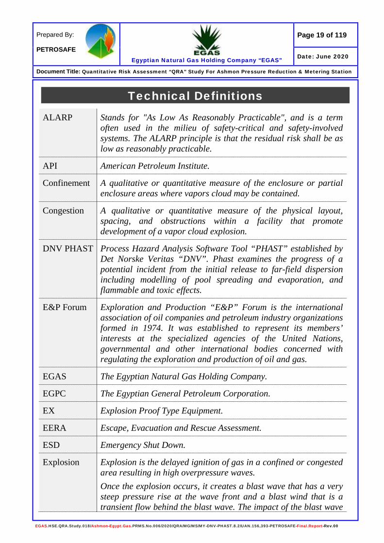
Technical Definitions
ALARP Stands for "As Low As Reasonably Practicable", and is a term often used in the milieu of safety-critical and safety-involved systems. The ALARP principle is that the residual risk shall be as low as reasonably practicable.
API American Petroleum Institute.
Confinement A qualitative or quantitative measure of the enclosure or partial enclosure areas where vapors cloud may be contained.
Congestion A qualitative or quantitative measure of the physical layout, spacing, and obstructions within a facility that promote development of a vapor cloud explosion.
DNV PHAST Process Hazard Analysis Software Tool “PHAST” established by Det Norske Veritas “DNV”. Phast examines the progress of a potential incident from the initial release to far-field dispersion including modelling of pool spreading and evaporation, and flammable and toxic effects.
E&P Forum Exploration and Production “E&P” Forum is the international association of oil companies and petroleum industry organizations formed in 1974. It was established to represent its members’ interests at the specialized agencies of the United Nations, governmental and other international bodies concerned with regulating the exploration and production of oil and gas.
EGAS The Egyptian Natural Gas Holding Company.
EGPC The Egyptian General Petroleum Corporation.
EX Explosion Proof Type Equipment.
EERA Escape, Evacuation and Rescue Assessment.
ESD Emergency Shut Down.
Explosion Explosion is the delayed ignition of gas in a confined or congested area resulting in high overpressure waves. Once the explosion occurs, it creates a blast wave that has a very steep pressure rise at the wave front and a blast wind that is a transient flow behind the blast wave. The impact of the blast wave

Page 20 of 119
Egyptian Natural Gas Holding Company “EGAS”
Prepared By: PETROSAFE
Date: June 2020
Document Title: Quantitative Risk Assessment “QRA” Study For Ashmon Pressure Reduction & Metering Station
EGAS.HSE.QRA.Study.018/Ashmon-Egypt.Gas.PRMS.No.006/2020/QRA/MG/MS/MY-DNV-PHAST.8.2/UAN.156,393-PETROSAFE-Final.Report-Rev.00
on structure near the explosion known as blast loading. The two important aspects of the blast loading concern are the prediction of the magnitude of the blast and of the pressure loading onto the local structures. Pressure loading predication as result of a blast; resemble a pulse of trapezoidal or triangular shape. They normally have duration of between approximately 40 msec and 400 msec. The time to maximum pressure is typically 20 msec. Primary damage from an explosion may result from several events: 1. Overpressure - the pressure developed between the expanding
gas and its surrounding atmosphere. 2. Pulse - the differential pressure across a plant as a pressure
wave passes might cause collapse or movement, both positive and negative.
3. Missiles and Shrapnel - are whole or partial items that are thrown by the blast of expanding gases that might cause damage or event escalation. In general, these “missiles” from atmospheric vapor cloud explosions cause minor impacts to process equipment since insufficient energy is available to lift heavy objects and cause major impacts. Small projectile objects are still a hazard to personnel and may cause injuries and fatalities. Impacts from rupture incidents may produce catastrophic results.
(ETA) Event Tree Analysis
Is a forward, bottom up, logical modeling technique for both success and failure that explores responses through a single initiating event and lays a path for assessing probabilities of the outcomes and overall system analysis. This analysis technique used to analyze the effects of functioning or failed systems, given that an event has occurred.
Failure Rate Is the frequency with which an engineered system or component fails, expressed in failures per unit of time. It is highly used in reliability engineering.
GASCO The Egyptian Natural Gas Company.
Gas Cloud Dispersion
Gas cloud air dilution naturally reduces the concentration to below the LEL or no longer considered ignitable (typically defined as 50 % of the LEL).
Page 21 of 119
Egyptian Natural Gas Holding Company “EGAS”
Prepared By: PETROSAFE
Date: June 2020
Document Title: Quantitative Risk Assessment “QRA” Study For Ashmon Pressure Reduction & Metering Station
EGAS.HSE.QRA.Study.018/Ashmon-Egypt.Gas.PRMS.No.006/2020/QRA/MG/MS/MY-DNV-PHAST.8.2/UAN.156,393-PETROSAFE-Final.Report-Rev.00
HSE Policy Health, Safety and Environmental Policy.
Hazard An inherent physical or chemical characteristic (flammability, toxicity, corrosively, stored chemical or mechanical energy) or set of conditions that has the potential for causing harm to people, property, or the environment.
(HAZOP) Hazard And Operability Study
Is a structured and systematic examination of a planned or existing process or operation in order to identify and evaluate problems that may represent risks to personnel or equipment, or prevent efficient operation. The HAZOP technique is qualitative, and aims to stimulate the imagination of participants to identify potential hazards and operability problems; structure and completeness given by using guideword prompts.
(HAZID) Hazard Identification Study
Is a tool for hazard identification, used early in a project as soon as process flow diagrams, draft heat and mass balances, and plot layouts are available. Existing site infrastructure, weather, and Geotechnical data also required, these being a source of external hazards.
(HAC) Hazardous Area Classification
When electrical equipment is used in, around, or near an atmosphere that has flammable gases or vapors, flammable liquids, combustible dusts, ignitable fibers or flying’s, there is always a possibility or risk that a fire or explosion might occur. Those areas where the possibility or risk of fire or explosion might occur due to an explosive atmosphere and/or mixture is often called a hazardous (or classified) location/area.
(IR) Individual Risk
The risk to a single person inside a particular building. Maximum individual risk is the risk to the most-exposed person and assumes that the person is exposed.
Jet Fire A jet fire is a pressurized stream of combustible gas or atomized liquid (such as a high-pressure release from a gas pipe or wellhead blowout event) that is burning. If such a release is ignited soon after it occurs, (i.e., within 2 - 3 minutes), the result is an intense jet flame. This jet fire stabilizes to a point that is close to the source of release, until the release stopped. A jet fire is usually a very localized, but very destructive to anything close to it. This is partly because as well as producing thermal radiation, the jet fire causes considerable convective heating in the region
Page 22 of 119
Egyptian Natural Gas Holding Company “EGAS”
Prepared By: PETROSAFE
Date: June 2020
Document Title: Quantitative Risk Assessment “QRA” Study For Ashmon Pressure Reduction & Metering Station
EGAS.HSE.QRA.Study.018/Ashmon-Egypt.Gas.PRMS.No.006/2020/QRA/MG/MS/MY-DNV-PHAST.8.2/UAN.156,393-PETROSAFE-Final.Report-Rev.00
beyond the tip of the flame. The high velocity of the escaping gas entrains air into the gas "jet" causing more efficient combustion to occur than in pool fires. Consequentially, a much higher heat transfer rate occurs to any object immersed in the flame, i.e., over 200 kW/m2 (62,500 Btdsq. ft) for a jet fire than in a pool fire flame. Typically, the first 10% of a jet fire length is conservatively considered un-ignited gas, as a result of the exit velocity causing the flame to lift off the gas point of release. This effect has been measured on hydrocarbon facility flares at 20% of the jet length, but a value of 10% is used to account for the extra turbulence around the edges of a real release point as compared to the smooth gas release from a flare tip. Jet flames have a relatively cool core near the source. The greatest heat flux usually occurs at impingement distances beyond 40% of the flame length, from its source. The greatest heat flux is not necessarily on the directly impinged side.
kW/m2 Kilowatt per square meter – unit for measuring the heat radiation (or heat flux).
LFL / LEL Lower Flammable Limit / Lower Explosive Limit - The lowest concentration (percentage) of a gas or a vapor in air capable of producing a flash of fire in presence of an ignition source.
MSDS Material Safety Data Sheet.
mm Hg A millimeter of mercury is a manometeric unit of pressure, formerly defined as the extra pressure generated by a column of mercury one millimeter high.
MEL Maximum Exposure Limit.
NFPA National Fire Protection Association.
N North Direction.
NE Northern East Direction.
NW Northern West Direction.
N/D Not Determined.
Page 23 of 119
Egyptian Natural Gas Holding Company “EGAS”
Prepared By: PETROSAFE
Date: June 2020
Document Title: Quantitative Risk Assessment “QRA” Study For Ashmon Pressure Reduction & Metering Station
EGAS.HSE.QRA.Study.018/Ashmon-Egypt.Gas.PRMS.No.006/2020/QRA/MG/MS/MY-DNV-PHAST.8.2/UAN.156,393-PETROSAFE-Final.Report-Rev.00
N/R Not Reached.
OGP Oil and Gas Producers.
ppm Part Per Million.
PRMS Pressure Reduction and Metering Station.
P&ID’s Piping and Instrumentation Diagrams.
PETROSAFE Petroleum Safety and Environmental Services Company.
QRA Quantitative Risk Assessment Study is a formal and systematic approach to estimating the likelihood and consequences of hazardous events, and expressing the results quantitatively as risk to people, the environment or your business.
Risk Relates to the probability of exposure to a hazard, which could result in harm to personnel, the environment or public. Risk is a measure of potential for human injury or economic loss in terms of both the incident likelihood and the magnitude of the injury / loss.
Risk Assessment
The identification and analysis, either qualitative or quantitative, of the likelihood and outcome of specific events or scenarios with judgments of probability and consequences.
scm/hr Standard Cubic Meter Per Hour. SCBA Self-Contained Breathing Apparatus. SE Southern East Direction. SW Southern West Direction. TWA Time Weighted Averages. UFL/UEL Upper flammable limit, the flammability limit describing the
richest flammable mixture of a combustible gas. UVCE When a flammable vapor is released, its mixture with air will form
a flammable vapor cloud. If ignited, the flame speed may accelerate to high velocities and produce significant blast overpressure.
V Volume.
Vapor Cloud Explosion (VCE)
An explosion in air of a flammable material cloud.
Page 24 of 119
Egyptian Natural Gas Holding Company “EGAS”
Prepared By: PETROSAFE
Date: June 2020
Document Title: Quantitative Risk Assessment “QRA” Study For Ashmon Pressure Reduction & Metering Station
EGAS.HSE.QRA.Study.018/Ashmon-Egypt.Gas.PRMS.No.006/2020/QRA/MG/MS/MY-DNV-PHAST.8.2/UAN.156,393-PETROSAFE-Final.Report-Rev.00
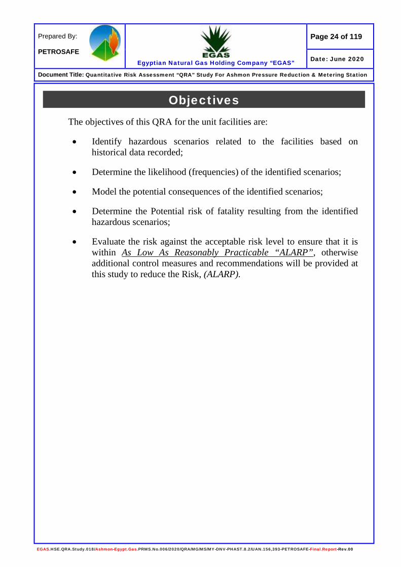
Objectives The objectives of this QRA for the unit facilities are:
• Identify hazardous scenarios related to the facilities based on historical data recorded;
• Determine the likelihood (frequencies) of the identified scenarios;
• Model the potential consequences of the identified scenarios;
• Determine the Potential risk of fatality resulting from the identified hazardous scenarios;
• Evaluate the risk against the acceptable risk level to ensure that it is within As Low As Reasonably Practicable “ALARP”, otherwise additional control measures and recommendations will be provided at this study to reduce the Risk, (ALARP).
Page 25 of 119
Egyptian Natural Gas Holding Company “EGAS”
Prepared By: PETROSAFE
Date: June 2020
Document Title: Quantitative Risk Assessment “QRA” Study For Ashmon Pressure Reduction & Metering Station
EGAS.HSE.QRA.Study.018/Ashmon-Egypt.Gas.PRMS.No.006/2020/QRA/MG/MS/MY-DNV-PHAST.8.2/UAN.156,393-PETROSAFE-Final.Report-Rev.00
Quantitative Risk Assessment Study Scope The scope of work of this QRA study is limited to the following:
• Identification of the Most Critical Event(s) or scenarios that may lead to fatal accidents as well as to ensure that the expected risk will not exceed the Acceptable Risk Level as per national and international standards;
• To assess and quantify the risks associated with Ashmon PRMS and the off-take point on the neighboring / surrounding community;
• The study determines Frequencies, Consequences (Including Associated Effect Contours) and Potential Risk of Fatality for the identified hazardous scenarios;
• Normal operation of the facilities (e.g. Construction and specific maintenance activities) are excluded from this analysis.

Page 26 of 119
Egyptian Natural Gas Holding Company “EGAS”
Prepared By: PETROSAFE
Date: June 2020
Document Title: Quantitative Risk Assessment “QRA” Study For Ashmon Pressure Reduction & Metering Station
EGAS.HSE.QRA.Study.018/Ashmon-Egypt.Gas.PRMS.No.006/2020/QRA/MG/MS/MY-DNV-PHAST.8.2/UAN.156,393-PETROSAFE-Final.Report-Rev.00
Quantitative Risk Assessment “QRA” Studies Method of Assessment
1.0- General Method Used Attention mainly focussed on those accidents where a gross failure of containment could result in the generation of a large vapour cloud of flammable or toxic material. The approach adopted has involved the following stages:
• Identification of hazardous materials, • Establishment of maximum total inventories and location.
During the site visit by the study team, the overall functioning of the site discussed in some detail and the Companies asked to provide a complete list of holdings of hazardous materials. A preliminary survey notes was issued by the team, as a private communication to the company concerned, and this formed the basis for subsequent more discussion and analysis. From the PRMS design model provided by the client, it was impractical to examine in depth all possible failure modes for all parts within the time allowed for this study. Instead, only those potential failures, which might contribute, either directly or indirectly, to off-site risks were examined.
2.0- Risk Assessment As the PRMS designed and prepared for construction, so it was therefore necessary for the study team to identify and analyse the hazards potential from first principles the routes by which a single or multiple accident could affect the community or neighbouring. The terms of reference required the team to investigate and determine the overall risk to health and safety both from individual installations and then foreseeable interactions. The assessment of risk in a complex situation is difficult. No method is perfect as all have advantages and limitations. It was agreed that the quantitative approach was the most meaningful way of comparing and evaluating different risks. The risk assessment framework shown in Figure (1) used for the study.

Page 27 of 119
Egyptian Natural Gas Holding Company “EGAS”
Prepared By: PETROSAFE
Date: June 2020
Document Title: Quantitative Risk Assessment “QRA” Study For Ashmon Pressure Reduction & Metering Station
EGAS.HSE.QRA.Study.018/Ashmon-Egypt.Gas.PRMS.No.006/2020/QRA/MG/MS/MY-DNV-PHAST.8.2/UAN.156,393-PETROSAFE-Final.Report-Rev.00
Figure (1) Risk Assessment Framework
Data Identify Hazards
Failure Case Definition
Scenario Development
Analysis of Consequences
Impact Assessment
Estimate / Measure Risks
Evaluate Risks
Decide Risk Reduction Measures
Verify
Tolerability Criteria
Frequency Analysis

Page 28 of 119
Egyptian Natural Gas Holding Company “EGAS”
Prepared By: PETROSAFE
Date: June 2020
Document Title: Quantitative Risk Assessment “QRA” Study For Ashmon Pressure Reduction & Metering Station
EGAS.HSE.QRA.Study.018/Ashmon-Egypt.Gas.PRMS.No.006/2020/QRA/MG/MS/MY-DNV-PHAST.8.2/UAN.156,393-PETROSAFE-Final.Report-Rev.00
Modeling the Consequences Modeling of the consequences is one of the key steps in Quantitative Risk Assessment “QRA”, as it provides the link between hazard identification (in this study Potential Loss of Containment Incidents) and the determination of possible impact of those incidents on People (Worker / Public), Asset and the Environment. In this study, Natural Gas (Mainly Methane CH4) was considered. There are several types of consequences to be considered for modelling, these include Gas Dispersion (UFL - LFL - 50 % LFL) / Heat Radiation / Explosion Overpressure modeling, also each of these scenarios described in the following table:
Table (1) Description of Modeling of the Different Scenario
Discharge Modeling Modeling of the mass release rate and its variation overtime.
Radiation Modeling Modeling of the Thermal radiation from fires.
Dispersion Modeling Modeling of the Gas and two-phase releases.
Overpressure Associated with explosions or pressure burst.
Toxic hazards are considered as result of releases / loss of containment for which discharge modeling and gas dispersion modeling are required. The hazard ranges are dependent upon the condition of the release pressure and rate of release. There are a number of commercial software for modeling gas dispersion, fire, explosion and toxic releases. PETROSAFE select the DNV PHAST Ver. 8.2 Software package in modeling scenarios. The software developed by DNV in order to provide a standard and validated set of consequence models that can be used to predict the effects of a release of hydrocarbon or chemical liquid or vapour. (Results of the modeling presented in pages from 53 to 97)
Page 29 of 119
Egyptian Natural Gas Holding Company “EGAS”
Prepared By: PETROSAFE
Date: June 2020
Document Title: Quantitative Risk Assessment “QRA” Study For Ashmon Pressure Reduction & Metering Station
EGAS.HSE.QRA.Study.018/Ashmon-Egypt.Gas.PRMS.No.006/2020/QRA/MG/MS/MY-DNV-PHAST.8.2/UAN.156,393-PETROSAFE-Final.Report-Rev.00
Criterion for Risk Tolerability The main function of this phase of the work was to assess the effectiveness of the proposed arrangement for managing risks against performance standards. In order to do this, we need firstly to define a performance standard and secondly, to be able to analyse the effectiveness of the arrangements in a manner which permits a direct comparison with these standards. The defining of performance standards undertakes at the following three levels:
• Policy-based • System • Technical
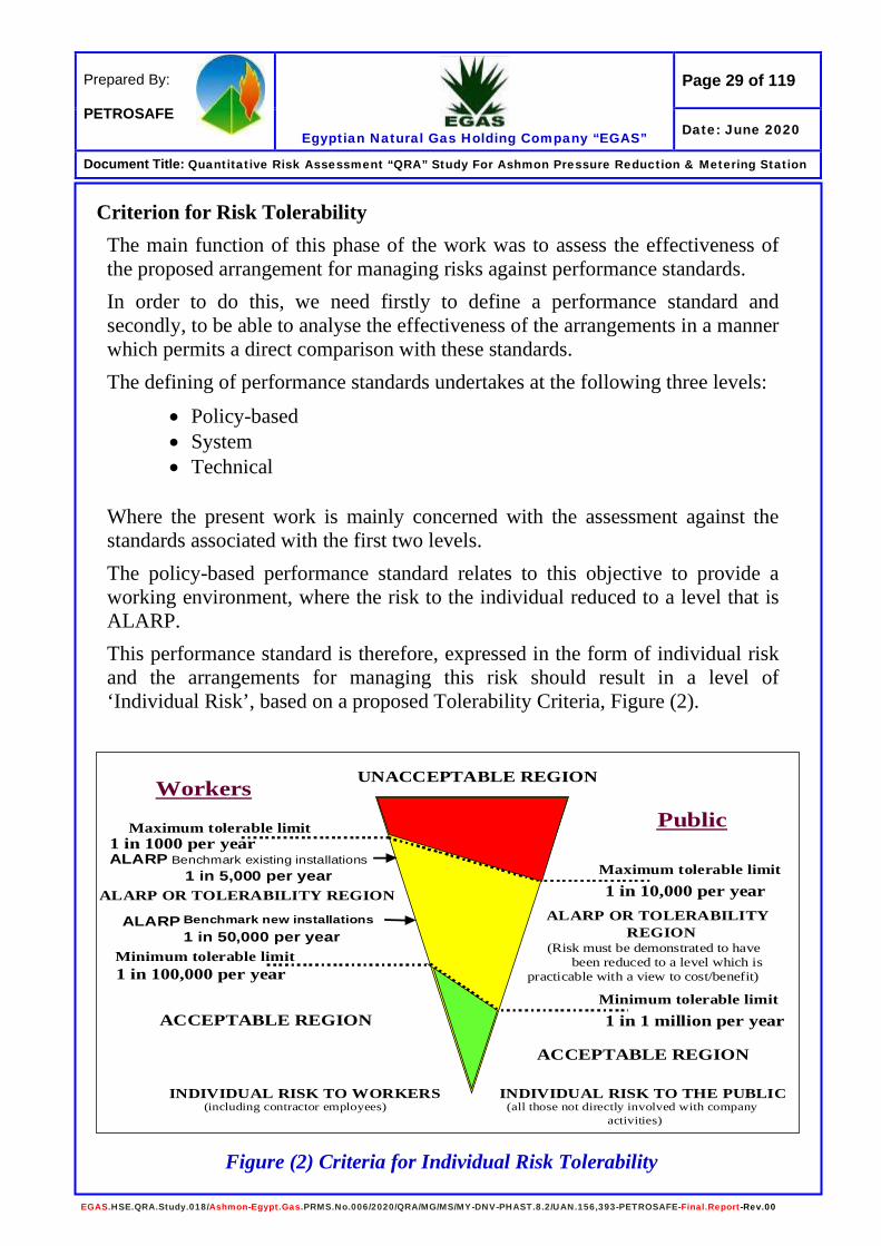
Where the present work is mainly concerned with the assessment against the standards associated with the first two levels. The policy-based performance standard relates to this objective to provide a working environment, where the risk to the individual reduced to a level that is ALARP. This performance standard is therefore, expressed in the form of individual risk and the arrangements for managing this risk should result in a level of ‘Individual Risk’, based on a proposed Tolerability Criteria, Figure (2).
Figure (2) Criteria for Individual Risk Tolerability
UNACCEPTABLE REGION
ACCEPTABLE REGION
ACCEPTABLE REGION
(Risk must be demonstrated to have been reduced to a level which is
practicable with a view to cost/benefit)
INDIVIDUAL RISK TO WORKERS(including contractor employees)
INDIVIDUAL RISK TO THE PUBLIC(all those not directly involved with company
activities)
ALARP Benchmark existing installations1 in 5,000 per year
ALARP Benchmark new installations 1 in 50,000 per year
ALARP OR TOLERABILITY REGIONALARP OR TOLERABILITY
REGION
Maximum tolerable limit1 in 1000 per year
Maximum tolerable limit1 in 10,000 per year
Minimum tolerable limit1 in 1 million per year
Minimum tolerable limit1 in 100,000 per year
WorkersPublic

Page 30 of 119
Egyptian Natural Gas Holding Company “EGAS”
Prepared By: PETROSAFE
Date: June 2020
Document Title: Quantitative Risk Assessment “QRA” Study For Ashmon Pressure Reduction & Metering Station
EGAS.HSE.QRA.Study.018/Ashmon-Egypt.Gas.PRMS.No.006/2020/QRA/MG/MS/MY-DNV-PHAST.8.2/UAN.156,393-PETROSAFE-Final.Report-Rev.00
The criterion for IR tolerability for workers and to the public outlined in Table (2) and Figure (3). It should be noted that these criteria proposed only as a guideline. Risk assessment is no substitute to professional judgement.
Table (2) Proposed Individual Risk (IR) Criteria (per person/year)
Risk Level Workers Public
Intolerable > 10-3 per person/yr. > 10-4 per person/yr.
Negligible > 10-5 per person/yr. > 10-6 per person/yr.
Figure (3) Proposed Individual Risk Criteria
Workers would include the Company employees and contractors. The public includes the public, visitors, and any third party who is not directly involved in the Company work activities. On this basis, we have chosen to set our level of intolerability at Individual Risk for workers of 1 in 1,000 per year, and we define an individual risk of 1 in 100,000 per year as broadly acceptable. Consequently, our ALARP region is between 1 in 1,000 and 1 in 100,000 per person/year. It is important to ensure that conflict between these subordinate standards and those stemming from international codes and standards are avoided and that any subordinate standards introduced are at least on a par with or augment those standards, which are associated with compliance with these international requirements. These system level performance standards are included as part of
ALARP Region
1 in 10,000
ALARP Region
1 in 1000
1 in 100,000 1 in 1 miillion
Individual Risk to Personnel Individual Risk to the Public
Page 31 of 119
Egyptian Natural Gas Holding Company “EGAS”
Prepared By: PETROSAFE
Date: June 2020
Document Title: Quantitative Risk Assessment “QRA” Study For Ashmon Pressure Reduction & Metering Station
EGAS.HSE.QRA.Study.018/Ashmon-Egypt.Gas.PRMS.No.006/2020/QRA/MG/MS/MY-DNV-PHAST.8.2/UAN.156,393-PETROSAFE-Final.Report-Rev.00
the summaries from the QRA. These used as the basis for assessing the suitability and sufficiency of Egypt Gas Site arrangements for both protecting personnel on site and members of public from major hazards and securing effective response in an emergency. Failure to meet acceptance criteria at this level results in the identification of remedial measures for assessment both qualitatively and quantitatively. The analytical work uses a system analysis approach and divided into a number of distinct phases:
• Data collection, including results from site-based qualitative assessments.
• Definition of arrangements. • Qualitative evaluation of arrangements against a catalogue of fire and
explosion hazards from other major accident hazards. • Preparing of event tree analysis models. • Consolidation of list of design events. • Analysis of the effect of design events on fire, explosion and toxic
hazard management and emergency response arrangements.
• Quantification of that impact in terms of individual risk. The main model would base on a systems approach, and it takes the following form:
• Estimates of incremental individual risk (IIR) per person/yr. • Is caused-consequences based. • Uses event tree analysis to calculate the frequency of occurrence. • Estimates incremental individual risk utilizing event tree analysis,
based on modeling the emergency response arrangements from detection through to recovery to a place of safety.

Page 32 of 119
Egyptian Natural Gas Holding Company “EGAS”
Prepared By: PETROSAFE
Date: June 2020
Document Title: Quantitative Risk Assessment “QRA” Study For Ashmon Pressure Reduction & Metering Station
EGAS.HSE.QRA.Study.018/Ashmon-Egypt.Gas.PRMS.No.006/2020/QRA/MG/MS/MY-DNV-PHAST.8.2/UAN.156,393-PETROSAFE-Final.Report-Rev.00
Personnel Vulnerability and Structural Damage A criterion used in the QRA study for the calculation of personnel vulnerability and structural / asset damage because of fire, explosion and toxic release shown in Table (3). The criteria shown below provide some assumptions for the impairment effects of hydrocarbon releases on personnel and structures, which based on Health and Safety Executive: Methods of approximation and determination of human vulnerability for offshore major accident hazard assessment.
Table (3) Criteria for Personnel Vulnerability and Structural Damage
Event Type Threshold of Fatality Asset/Structural Damage
Jet and Diffusive Fire
Impingement
6.3 kW/ m2 (1)
12.5 kW/m2 (2)
- Flame impingement 10 minutes.
- 300 - 500 kW/m2
Structural Failure within 20 minutes.
Pool Fire Impingement 6.3 kW/ m2 (1)
12.5 kW/m2 (2)
- Flame impingement 20 minutes
- 100 - 150 kW/m2
Structural Failure within 30 minutes.
Smoke 2.3% v/v (3)
15% v/v (4)
Explosion Overpressure 300 mbar 100 mbar
(1) Fatality within 1 - 2 minutes (2) Fatal < 1 minute (3) Above 2.3%, escape possible but difficult (4) No escape possible, fatal in a few seconds
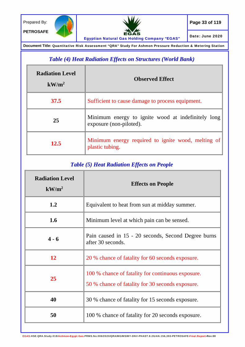
The effects of exposure to fire expressed in terms of heat radiation (kW/m2) and overpressure waves shown in Tables (4), (5) and (6).
Page 33 of 119
Egyptian Natural Gas Holding Company “EGAS”
Prepared By: PETROSAFE
Date: June 2020
Document Title: Quantitative Risk Assessment “QRA” Study For Ashmon Pressure Reduction & Metering Station
EGAS.HSE.QRA.Study.018/Ashmon-Egypt.Gas.PRMS.No.006/2020/QRA/MG/MS/MY-DNV-PHAST.8.2/UAN.156,393-PETROSAFE-Final.Report-Rev.00
Table (4) Heat Radiation Effects on Structures (World Bank)
Radiation Level
kW/m2 Observed Effect
37.5 Sufficient to cause damage to process equipment.
25 Minimum energy to ignite wood at indefinitely long exposure (non-piloted).
12.5 Minimum energy required to ignite wood, melting of plastic tubing.
Table (5) Heat Radiation Effects on People
Radiation Level
kW/m2 Effects on People
1.2 Equivalent to heat from sun at midday summer.
1.6 Minimum level at which pain can be sensed.
4 - 6 Pain caused in 15 - 20 seconds, Second Degree burns after 30 seconds.
12 20 % chance of fatality for 60 seconds exposure.
25 100 % chance of fatality for continuous exposure.
50 % chance of fatality for 30 seconds exposure.
40 30 % chance of fatality for 15 seconds exposure.
50 100 % chance of fatality for 20 seconds exposure.

Page 34 of 119
Egyptian Natural Gas Holding Company “EGAS”
Prepared By: PETROSAFE
Date: June 2020
Document Title: Quantitative Risk Assessment “QRA” Study For Ashmon Pressure Reduction & Metering Station
EGAS.HSE.QRA.Study.018/Ashmon-Egypt.Gas.PRMS.No.006/2020/QRA/MG/MS/MY-DNV-PHAST.8.2/UAN.156,393-PETROSAFE-Final.Report-Rev.00
Table (6) Effects of Overpressure
Pressure Effects / Damage
bar psig
0.002 0.03 Occasional breakage of glass windows.
0.006 0.1 Breakage of some small windows.
0.021 0.3 Probability of serious damage beyond this point = 0.05.
10 % glass broken.
0.027 0.4 Minor structural damage of buildings.
0.068 1.0 Partial collapse of walls and roofs, possible injuries.
0.137 2.0 Some severe injuries, death unlikely.
0.206 3.0 Steel frame buildings distorted / pulled from foundation.
0.275 4.0 Oil storage tanks ruptured.
0.344 5.0 Wooden utilities poles snapped / Fatalities.
0.41 6.0 Nearly complete destruction of building.
0.48 7.0 Loaded wagon train overturned.
0.689 10.0 Total destruction of buildings.

Page 35 of 119
Egyptian Natural Gas Holding Company “EGAS”
Prepared By: PETROSAFE
Date: June 2020
Document Title: Quantitative Risk Assessment “QRA” Study For Ashmon Pressure Reduction & Metering Station
EGAS.HSE.QRA.Study.018/Ashmon-Egypt.Gas.PRMS.No.006/2020/QRA/MG/MS/MY-DNV-PHAST.8.2/UAN.156,393-PETROSAFE-Final.Report-Rev.00
Quantification of the Frequency of Occurrence The probability of a sequence of events leading to a major hazard is dependent on the probability of each event in a sequence occurring; usually these probabilities may be multiplied together to obtain the end event probability or frequency. The technique of Quantified Risk Assessment ‘QRA’ requires data in the form of probability or frequency to be estimated for each input event. Ideally, data relating to hardware failures and human error that are specific to each plant should be obtained from the company’s maintenance and historical records. Unfortunately, records available were not in the form that allows data relevant to this study to be obtained. Therefore, other sources of data were used as a basis for failure/error scenarios. The sources of information and data are shown in the References section of this report.
Identification of Scenarios Leading to Selected Failures
For each selected failure scenario, the potential contributory factors were examined, taking into account any protective features available. Typically, the factors examined included:
• Operator error • Metallurgical fatigue or ageing of materials • Internal or external Corrosion • Loss of process control, e.g. pressure, temperature or flow, etc. • Overfilling of vessels • Introduction of impurities • Fire and/or explosion • Missiles • Flooding
Account was taken at this stage of those limited releases, which, although in themselves did not constitute a significant off-site hazard could, under some circumstances, initiate a sequence leading to a larger release, as a knock-on effect. It was noted that the proposed criterion for risk tolerability was used in Egypt by the following organizations: British Gas / British Petroleum / Shell / Total.
Page 36 of 119
Egyptian Natural Gas Holding Company “EGAS”
Prepared By: PETROSAFE
Date: June 2020
Document Title: Quantitative Risk Assessment “QRA” Study For Ashmon Pressure Reduction & Metering Station
EGAS.HSE.QRA.Study.018/Ashmon-Egypt.Gas.PRMS.No.006/2020/QRA/MG/MS/MY-DNV-PHAST.8.2/UAN.156,393-PETROSAFE-Final.Report-Rev.00
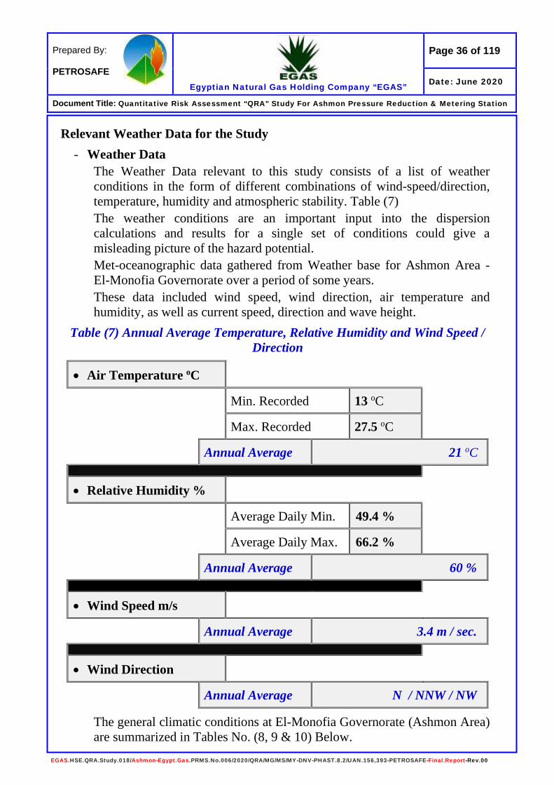
Relevant Weather Data for the Study - Weather Data
The Weather Data relevant to this study consists of a list of weather conditions in the form of different combinations of wind-speed/direction, temperature, humidity and atmospheric stability. Table (7) The weather conditions are an important input into the dispersion calculations and results for a single set of conditions could give a misleading picture of the hazard potential. Met-oceanographic data gathered from Weather base for Ashmon Area - El-Monofia Governorate over a period of some years. These data included wind speed, wind direction, air temperature and humidity, as well as current speed, direction and wave height.
Table (7) Annual Average Temperature, Relative Humidity and Wind Speed / Direction
• Air Temperature oC
Min. Recorded 13 oC
Max. Recorded 27.5 oC
Annual Average 21 oC
• Relative Humidity %
Average Daily Min. 49.4 %
Average Daily Max. 66.2 %
Annual Average 60 %
• Wind Speed m/s
Annual Average 3.4 m / sec.
• Wind Direction
Annual Average N / NNW / NW
The general climatic conditions at El-Monofia Governorate (Ashmon Area) are summarized in Tables No. (8, 9 & 10) Below.
Page 37 of 119
Egyptian Natural Gas Holding Company “EGAS”
Prepared By: PETROSAFE
Date: June 2020
Document Title: Quantitative Risk Assessment “QRA” Study For Ashmon Pressure Reduction & Metering Station
EGAS.HSE.QRA.Study.018/Ashmon-Egypt.Gas.PRMS.No.006/2020/QRA/MG/MS/MY-DNV-PHAST.8.2/UAN.156,393-PETROSAFE-Final.Report-Rev.00
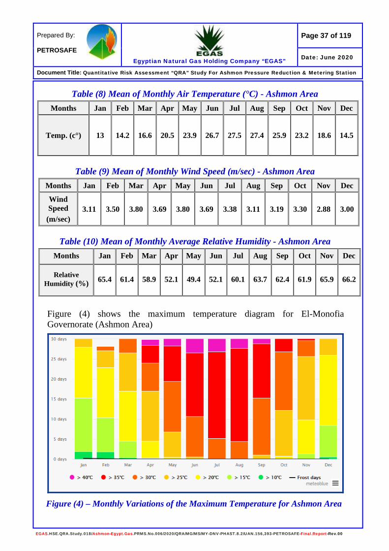
Table (8) Mean of Monthly Air Temperature (°C) - Ashmon Area
Table (9) Mean of Monthly Wind Speed (m/sec) - Ashmon Area Months Jan Feb Mar Apr May Jun Jul Aug Sep Oct Nov Dec
Wind Speed (m/sec)
3.11 3.50 3.80 3.69 3.80 3.69 3.38 3.11 3.19 3.30 2.88 3.00
Table (10) Mean of Monthly Average Relative Humidity - Ashmon Area
Figure (4) shows the maximum temperature diagram for El-Monofia Governorate (Ashmon Area)
Months Jan Feb Mar Apr May Jun Jul Aug Sep Oct Nov Dec
Temp. (c°) 13 14.2 16.6 20.5 23.9 26.7 27.5 27.4 25.9 23.2 18.6 14.5
Months Jan Feb Mar Apr May Jun Jul Aug Sep Oct Nov Dec
Relative Humidity (%)
65.4 61.4 58.9 52.1 49.4 52.1 60.1 63.7 62.4 61.9 65.9 66.2
Figure (4) – Monthly Variations of the Maximum Temperature for Ashmon Area

Page 38 of 119
Egyptian Natural Gas Holding Company “EGAS”
Prepared By: PETROSAFE
Date: June 2020
Document Title: Quantitative Risk Assessment “QRA” Study For Ashmon Pressure Reduction & Metering Station
EGAS.HSE.QRA.Study.018/Ashmon-Egypt.Gas.PRMS.No.006/2020/QRA/MG/MS/MY-DNV-PHAST.8.2/UAN.156,393-PETROSAFE-Final.Report-Rev.00
Figures (5 & 6) show the monthly variations of the wind speed as well as wind rose for El-Monofia Governorate (Ashmon Area) respectively.
Figure (6) –Wind Rose for Ashmon Area
Figure (5) – Monthly Variations of the Wind Speed for Ashmon Area
Page 39 of 119
Egyptian Natural Gas Holding Company “EGAS”
Prepared By: PETROSAFE
Date: June 2020
Document Title: Quantitative Risk Assessment “QRA” Study For Ashmon Pressure Reduction & Metering Station
EGAS.HSE.QRA.Study.018/Ashmon-Egypt.Gas.PRMS.No.006/2020/QRA/MG/MS/MY-DNV-PHAST.8.2/UAN.156,393-PETROSAFE-Final.Report-Rev.00
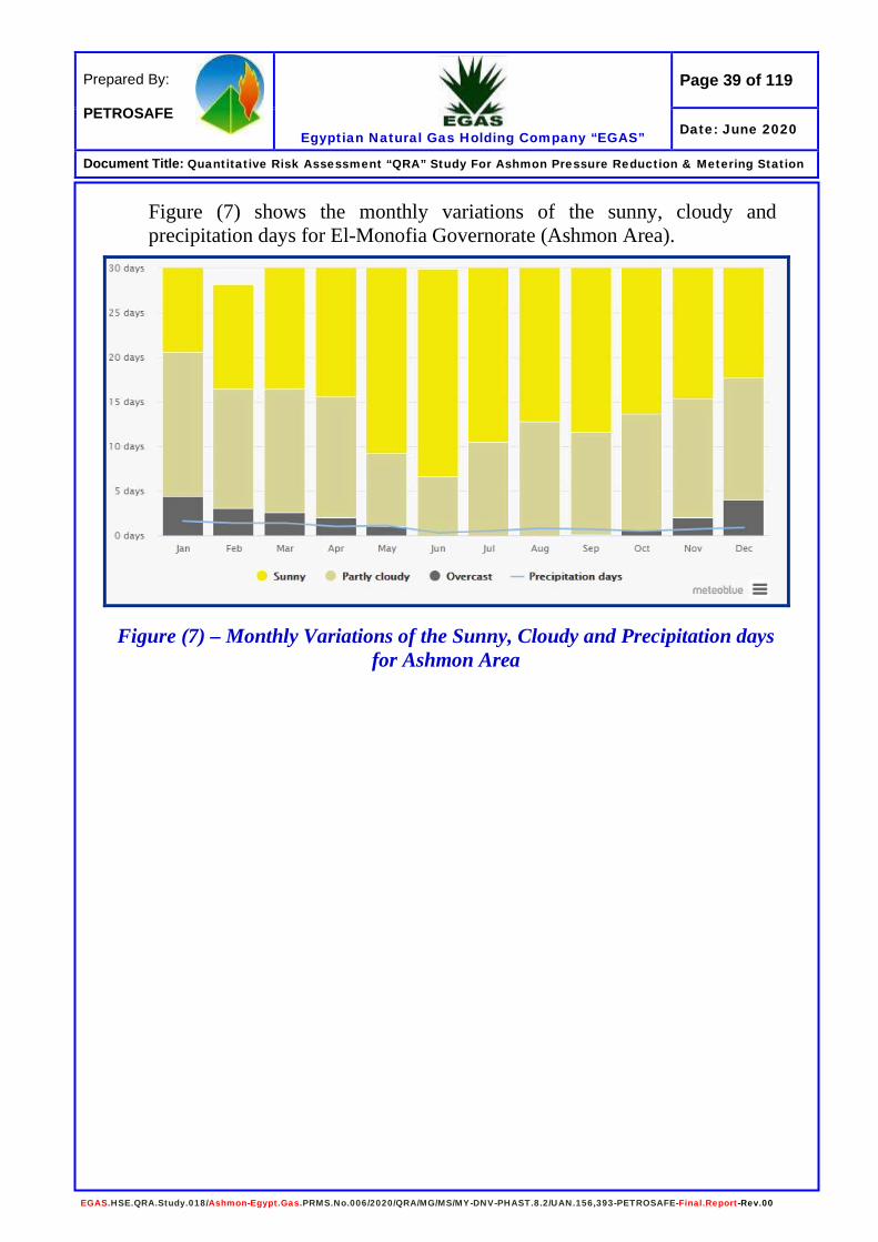
Figure (7) shows the monthly variations of the sunny, cloudy and precipitation days for El-Monofia Governorate (Ashmon Area).
Figure (7) – Monthly Variations of the Sunny, Cloudy and Precipitation days for Ashmon Area

Page 40 of 119
Egyptian Natural Gas Holding Company “EGAS”
Prepared By: PETROSAFE
Date: June 2020
Document Title: Quantitative Risk Assessment “QRA” Study For Ashmon Pressure Reduction & Metering Station
EGAS.HSE.QRA.Study.018/Ashmon-Egypt.Gas.PRMS.No.006/2020/QRA/MG/MS/MY-DNV-PHAST.8.2/UAN.156,393-PETROSAFE-Final.Report-Rev.00
- Stability Categories The two most significant variables, which would affect the dispersion calculations, are Wind-speed and atmospheric stability. The stability class is a measure of the atmospheric turbulence caused by thermal gradients. Pasqual Stability identifies six main categories, which shown in the Tables (11 & 12) and summarized in Table (13).
Table (11) Pasqual Stability Categories
A B C D E F
Very Unstable
Unstable Moderately Unstable
Neutral Moderately Stable
Stable
Neutral conditions correspond to a vertical temperature gradient of about 1o C per 100 m.
Table (12) Relationship between Wind Speed and Stability Wind speed
Day-time Solar Radiation
Night-time Cloud Cover
(m/s)
Strong
Medium
Slight
Thin <3/8
Medium >3/8
Overcast >4/5
<2 A A-B B - - D
2-3 A-B B C E F D
3-5 B B-C C D E D
5-6 C C-D D D D D
>6 C D D D D D
Table (13) Sets of Weather Conditions Initially Selected for this Study
Set for Wind Speed and Stability
Wind speed Stability
3.4 m/sec. D

Page 41 of 119
Egyptian Natural Gas Holding Company “EGAS”
Prepared By: PETROSAFE
Date: June 2020
Document Title: Quantitative Risk Assessment “QRA” Study For Ashmon Pressure Reduction & Metering Station
EGAS.HSE.QRA.Study.018/Ashmon-Egypt.Gas.PRMS.No.006/2020/QRA/MG/MS/MY-DNV-PHAST.8.2/UAN.156,393-PETROSAFE-Final.Report-Rev.00
Ashmon PRMS Description Background
Ashmon Pressure Reduction and Metering Station Operated by Egypt Gas Company. It is located about 7 km South direction from Ashmon City downtown. The PRMS will provide the natural gas to Ashmon and surrounding area public housing. The PRMS feeding will be from the National Gas Pipeline owned by GASCO and the off-take point will be at distance of 250 m from the PRS boundary. The off-take point pressure will be from 25 to 70 bar, and then the pressure reduced to 4/7 bar at the PRMS facilities with adding odorant, and then connected to the internal distribution network to public housing at Ashmon and surrounding area.
The PRMS & Off-Take Point Location Coordinates (Egypt Gas Data) PRMS Off-take Point
Point North (N) East (E) North (N) East (E) 1 30°13'42.98" 30°58'40.81" 30°13'40.11" 30°58'49.76" 2 30°13'41.51" 30°58'41.60" 30°13'39.80" 30°58'49.87" 3 30°13'40.97" 30°58'39.83" 30°13'39.70" 30°58'49.52" 4 30°13'42.44" 30°58'39.05" 30°13'40.02" 30°58'49.40"
PRMS Brief Description and Components (Egypt Gas Data) The PRMS will be surround by 3 m height fence and mainly consist of the followings: (Ref. Figures 8, 9, 10 and 11) - Inlet module: which contains 4” # 600 manual isolation valve. - Filter module: two identical streams each contain inlet and outlet
isolation valves. - Heating system module: two identical. - Metering module: two identical. - Regulating module: two identical regulating lines. - Outlet module: it contains manual outlet isolation valve. - Odorant module: 600 lit. capacity bulk tank / 50 lit. daily use. - Off-take point will be from up-ground room surrounded by 3 m height
brick wall fence containing connection pipes and isolation valves with GASCO underground pipeline 32”, connected to 4” PRMS feeding pipeline.
- Security Office (one floor) - Administration office (one floor) - Firefighting Facilities (Fire Water Tank / Pumps / Fire water Network)

Page 42 of 119
Egyptian Natural Gas Holding Company “EGAS”
Prepared By: PETROSAFE
Date: June 2020
Document Title: Quantitative Risk Assessment “QRA” Study For Ashmon Pressure Reduction & Metering Station
EGAS.HSE.QRA.Study.018/Ashmon-Egypt.Gas.PRMS.No.006/2020/QRA/MG/MS/MY-DNV-PHAST.8.2/UAN.156,393-PETROSAFE-Final.Report-Rev.00
Ashmon PRMS Units (Egypt Gas Data) Table (14) Ashmon PRMS Units
No
PRMS Units Capacity Size 1 Inlet unit
Inlet valve 10000 scmh 4"
Inlet valve bypass (ball + plug) 2500 scmh 2"
2 Filter units
Line Fl 5000 scmh 3" X 2"
Line F2 5000 scmh 3" X 2"
Line F3 (only two valves) 5000 scmh 3" X 2"
Line F3 (only blind flange)
Line F4 (only blind flange)
3 Meter unit
Line Ml 5000 scmh 2" X 3" X 2"
Line M2 5000 scmh 2" X 3" X 2"
Line M3 (only two valves) 5000 scmh 2" X 2"
Line M3 (only blind flange)
Line M4 (only blind flange)
One extension ball valve on outlet header (future heater) 10000 scmh 3"
One ball valve full bore for heater bypass 10000 scmh 3"
4 Regulator unit
Line Rl 5000 scmh 2" X 4"
Line R2 5000 scmh 2" X 4"
Line R3(only two valves) 5000 scmh 2" X 4"
Line R3(only blind flange)

Page 43 of 119
Egyptian Natural Gas Holding Company “EGAS”
Prepared By: PETROSAFE
Date: June 2020
Document Title: Quantitative Risk Assessment “QRA” Study For Ashmon Pressure Reduction & Metering Station
EGAS.HSE.QRA.Study.018/Ashmon-Egypt.Gas.PRMS.No.006/2020/QRA/MG/MS/MY-DNV-PHAST.8.2/UAN.156,393-PETROSAFE-Final.Report-Rev.00
Line R4(only blind flange)
One extension ball valve on inlet header (future heater) 10000 scmh 3"
5 Odorant unit
Electrical pumps
Lapping system
6 Outlet unit
Outlet valve 10000 scmh 6"
Extension valve (future)
7 Monitoring and Control unit
8 Generator (15 KVA)
9 UPS

Page 44 of 119
Egyptian Natural Gas Holding Company “EGAS”
Prepared By: PETROSAFE
Date: June 2020
Document Title: Quantitative Risk Assessment “QRA” Study For Ashmon Pressure Reduction & Metering Station
EGAS.HSE.QRA.Study.018/Ashmon-Egypt.Gas.PRMS.No.006/2020/QRA/MG/MS/MY-DNV-PHAST.8.2/UAN.156,393-PETROSAFE-Final.Report-Rev.00
Figure (8) Ashmon Pressure Reduction and Metering Station “PRMS” General Layout (Egypt Gas Data)
PRMS
Inlet Point
Outlet Point
Control Room
Generator
Heater
Gas Feeding Pipeline
Firewater Tank
Firewater Pumps
50 m
50 m
50 m
50 m
G.R
Main Entrance
Escape Gate

Page 45 of 119
Egyptian Natural Gas Holding Company “EGAS”
Prepared By: PETROSAFE
Date: June 2020
Document Title: Quantitative Risk Assessment “QRA” Study For Ashmon Pressure Reduction & Metering Station
EGAS.HSE.QRA.Study.018/Ashmon-Egypt.Gas.PRMS.No.006/2020/QRA/MG/MS/MY-DNV-PHAST.8.2/UAN.156,393-PETROSAFE-Final.Report-Rev.00
Figure (9) Ashmon PRMS Piping and Instrumentation Diagram “P&ID” for Inlet & Filter Separator Section (Egypt Gas Data)
Page 46 of 119
Egyptian Natural Gas Holding Company “EGAS”
Prepared By: PETROSAFE
Date: June 2020
Document Title: Quantitative Risk Assessment “QRA” Study For Ashmon Pressure Reduction & Metering Station
EGAS.HSE.QRA.Study.018/Ashmon-Egypt.Gas.PRMS.No.006/2020/QRA/MG/MS/MY-DNV-PHAST.8.2/UAN.156,393-PETROSAFE-Final.Report-Rev.00
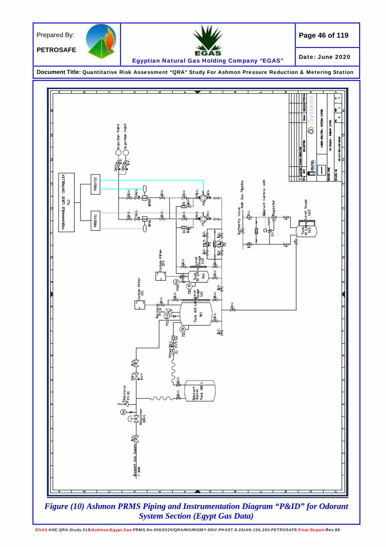
Figure (10) Ashmon PRMS Piping and Instrumentation Diagram “P&ID” for Odorant
System Section (Egypt Gas Data)
Page 47 of 119
Egyptian Natural Gas Holding Company “EGAS”
Prepared By: PETROSAFE
Date: June 2020
Document Title: Quantitative Risk Assessment “QRA” Study For Ashmon Pressure Reduction & Metering Station
EGAS.HSE.QRA.Study.018/Ashmon-Egypt.Gas.PRMS.No.006/2020/QRA/MG/MS/MY-DNV-PHAST.8.2/UAN.156,393-PETROSAFE-Final.Report-Rev.00
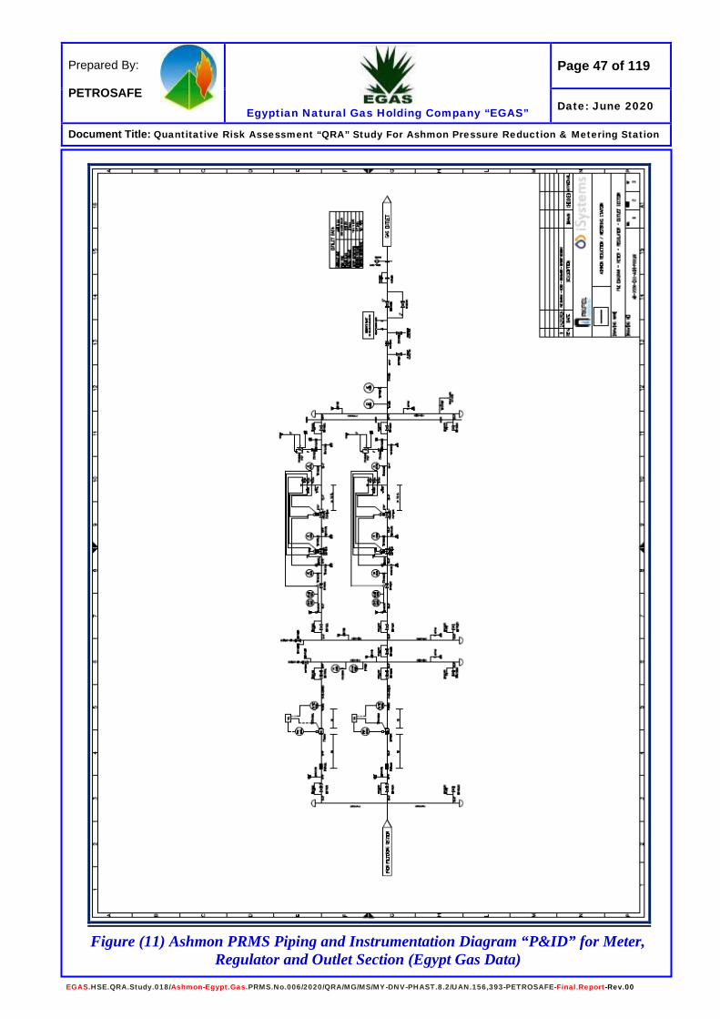
Figure (11) Ashmon PRMS Piping and Instrumentation Diagram “P&ID” for Meter, Regulator and Outlet Section (Egypt Gas Data)

Page 48 of 119
Egyptian Natural Gas Holding Company “EGAS”
Prepared By: PETROSAFE
Date: June 2020
Document Title: Quantitative Risk Assessment “QRA” Study For Ashmon Pressure Reduction & Metering Station
EGAS.HSE.QRA.Study.018/Ashmon-Egypt.Gas.PRMS.No.006/2020/QRA/MG/MS/MY-DNV-PHAST.8.2/UAN.156,393-PETROSAFE-Final.Report-Rev.00
Figure (12) Ashmon PRMS and Surroundings Plotted on Google Earth Photo
(1) PRMS Facility (A) Offtake (B) Main Road to PRS (C) Ezbet Sidi Ibrahim (D) Residential Building (E) Residential Building
PRS
Offtake
Distances Description (1) To (A) = 250 m (1) To (B) = 272 m (1) To (C) = 256 m (1) To (D) = 197 m (1) To (E) = 179 m
(1)
(A)
(B)
(C)
(D)
(E)
Page 49 of 119
Egyptian Natural Gas Holding Company “EGAS”
Prepared By: PETROSAFE
Date: June 2020
Document Title: Quantitative Risk Assessment “QRA” Study For Ashmon Pressure Reduction & Metering Station
EGAS.HSE.QRA.Study.018/Ashmon-Egypt.Gas.PRMS.No.006/2020/QRA/MG/MS/MY-DNV-PHAST.8.2/UAN.156,393-PETROSAFE-Final.Report-Rev.00
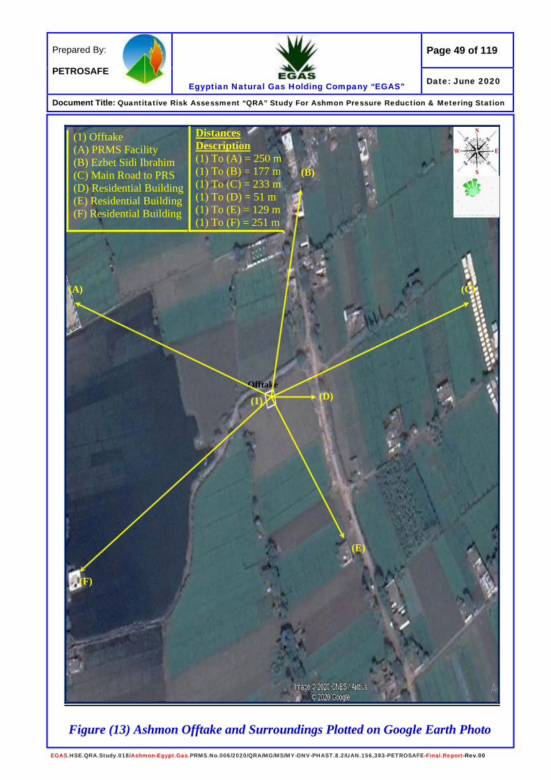
Figure (13) Ashmon Offtake and Surroundings Plotted on Google Earth Photo
Offtake
(1) Offtake (A) PRMS Facility (B) Ezbet Sidi Ibrahim (C) Main Road to PRS (D) Residential Building (E) Residential Building (F) Residential Building
Distances Description (1) To (A) = 250 m (1) To (B) = 177 m (1) To (C) = 233 m (1) To (D) = 51 m (1) To (E) = 129 m (1) To (F) = 251 m
(A)
(B)
(C)
(D)
(E)
(F)
(1)
Page 50 of 119
Egyptian Natural Gas Holding Company “EGAS”
Prepared By: PETROSAFE
Date: June 2020
Document Title: Quantitative Risk Assessment “QRA” Study For Ashmon Pressure Reduction & Metering Station
EGAS.HSE.QRA.Study.018/Ashmon-Egypt.Gas.PRMS.No.006/2020/QRA/MG/MS/MY-DNV-PHAST.8.2/UAN.156,393-PETROSAFE-Final.Report-Rev.00
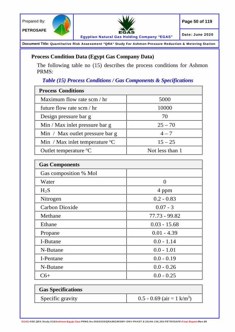
Process Condition Data (Egypt Gas Company Data) The following table no (15) describes the process conditions for Ashmon PRMS:
Table (15) Process Conditions / Gas Components & Specifications
Process Conditions Maximum flow rate scm / hr 5000 future flow rate scm / hr 10000 Design pressure bar g 70 Min / Max inlet pressure bar g 25 – 70 Min / Max outlet pressure bar g 4 – 7 Min / Max inlet temperature oC 15 – 25 Outlet temperature oC Not less than 1
Gas Components Gas composition % Mol Water 0 H2S 4 ppm Nitrogen 0.2 - 0.83 Carbon Dioxide 0.07 - 3 Methane 77.73 - 99.82 Ethane 0.03 - 15.68 Propane 0.01 - 4.39 I-Butane 0.0 - 1.14 N-Butane 0.0 - 1.01 I-Pentane 0.0 - 0.19 N-Butane 0.0 - 0.26 C6+ 0.0 - 0.25
Gas Specifications Specific gravity 0.5 - 0.69 (air = 1 k/m3)

Page 51 of 119
Egyptian Natural Gas Holding Company “EGAS”
Prepared By: PETROSAFE
Date: June 2020
Document Title: Quantitative Risk Assessment “QRA” Study For Ashmon Pressure Reduction & Metering Station
EGAS.HSE.QRA.Study.018/Ashmon-Egypt.Gas.PRMS.No.006/2020/QRA/MG/MS/MY-DNV-PHAST.8.2/UAN.156,393-PETROSAFE-Final.Report-Rev.00
Gas Odorant Specifications The odorant supplied with a Hazard Data Sheet and identified as Spotleak 1009. Spotleak is an aliphatic mixture in clear liquid form that is extremely flammable, with the following characteristics:
- Boiling Range 60-70o C - Flash Point -17.8o C - Freezing Point -45.5o C - Density (H2O = 1) 0.812 @ 15.5o C - Vapor Density 3.0 (air = 1) - Vapor Pressure (mm Hg) 6.6 @ 37.8o C
Health Hazards
Spotleak is not carcinogenic, but the major health hazards as a result of exposure to Spotleak include the following: Inhalation • Short-term exposure: Irritation and central nervous system effects • Long-term exposure: Irritation
Skin Contact • Short-term: Irritation • Long-term: Dermatitis
Eye Contact • Short-term: Irritation and tearing • Long-term: Irritation
Ingestion • Short-term: nausea, vomiting, central nervous system effects • Long-term: no effects are known
Hygiene Standards and Limits
Occupational Exposure Limit for Spotleak to all components is 45 ppm, and the long-term “MEL” should be below 12 ppm (8 hrs. “TWA”).
Fire and Explosion Hazards Spotleak is a severe fire hazard. Vapor/air mixtures are explosive. Vapor is 3 times heavier than air. Vapor may ignite at distant ignition sources and flash back. Thermal decomposition products include oxides of sulphur and hydrogen sulphide.

Page 52 of 119
Egyptian Natural Gas Holding Company “EGAS”
Prepared By: PETROSAFE
Date: June 2020
Document Title: Quantitative Risk Assessment “QRA” Study For Ashmon Pressure Reduction & Metering Station
EGAS.HSE.QRA.Study.018/Ashmon-Egypt.Gas.PRMS.No.006/2020/QRA/MG/MS/MY-DNV-PHAST.8.2/UAN.156,393-PETROSAFE-Final.Report-Rev.00
Fire Fighting and Protection Systems and Facilities As per minutes of the coordination meeting dated 20/07/2016 with Civil Protection, the PRMS will provided by the following fire protection facilities:
• Firewater tank with a capacity of 40 cum. • Firewater pumps (1 electrical & 1 diesel with capacity of 250 gpm
each). • Firewater main with a diameter of 4 inch. • Firewater hydrants 1.5 inch X 1 / each. • Firewater monitors. • Smoke detector in all admin rooms & FM200 firefighting system for
the control room. • Heat detectors in buffet rooms. • Smoke detectors in control rooms according to the area. • Different sizes of fire extinguishers will be distributed at PRMS site.
Emergency Response Plan “ERP” - Need to be provided by Egypt Gas The Emergency Response Plan “ERP” for Ashmon PRS not provided by Egypt Gas, so it must be prepared (if not) to include all related items including all scenarios has been identified by this QRA study.

Page 53 of 119
Egyptian Natural Gas Holding Company “EGAS”
Prepared By: PETROSAFE
Date: June 2020
Document Title: Quantitative Risk Assessment “QRA” Study For Ashmon Pressure Reduction & Metering Station
EGAS.HSE.QRA.Study.018/Ashmon-Egypt.Gas.PRMS.No.006/2020/QRA/MG/MS/MY-DNV-PHAST.8.2/UAN.156,393-PETROSAFE-Final.Report-Rev.00
Analytical Results of Consequence Modeling 1.0- Pressure Reduction Station Inlet Pipeline (4 inch)
1/1- Consequence Modeling for 1 inch (Pin Hole) Gas Release The following table no. (16) Show that:
Table (16) Dispersion Modeling for Inlet - 1” / 4” Gas Release Gas Release (Inlet / PRV “High Pressure”)
Wind Category Flammability Limits Distance (m) Height (m) Cloud Width (m)
3.4 D
UFL 1.4 1.06 0.12 @ 1.1 m
LFL 5.4 1.26 0.52 @ 3.5 m
50 % LFL 9.4 0 – 1.52 1.52 @ 6.00 m
Jet Fire
Wind Category
Flame Length
(m)
Heat Radiation (kW/m2)
Distance Downwind
(m)
Distance Crosswind
(m)
Lethality Level (%)
3.4 D 9.00
1.6 13.5 8.38 0
4 11.3 4.94 0
9.5 9.3 2.37 0
12.5 8.8 1.64 20% /60 sec.
25 Not Reached Not Reached 80.34
37.5 Not Reached Not Reached 98.74
Unconfined Vapor Cloud Explosion - UVCE (Open Air)
Wind Category
Pressure Value (bar)
Over Pressure Radius (m) Overpressure Waves
Effect / Damage Early Late
3.4 D
0.020 N/D N/D 0.021 bar
Probability of serious damage beyond this point = 0.05 - 10 % glass broken
0.137 N/D N/D 0.137 bar
Some severe injuries, death unlikely
0.206 N/D N/D 0.206 bar
Steel frame buildings distorted / pulled from foundation
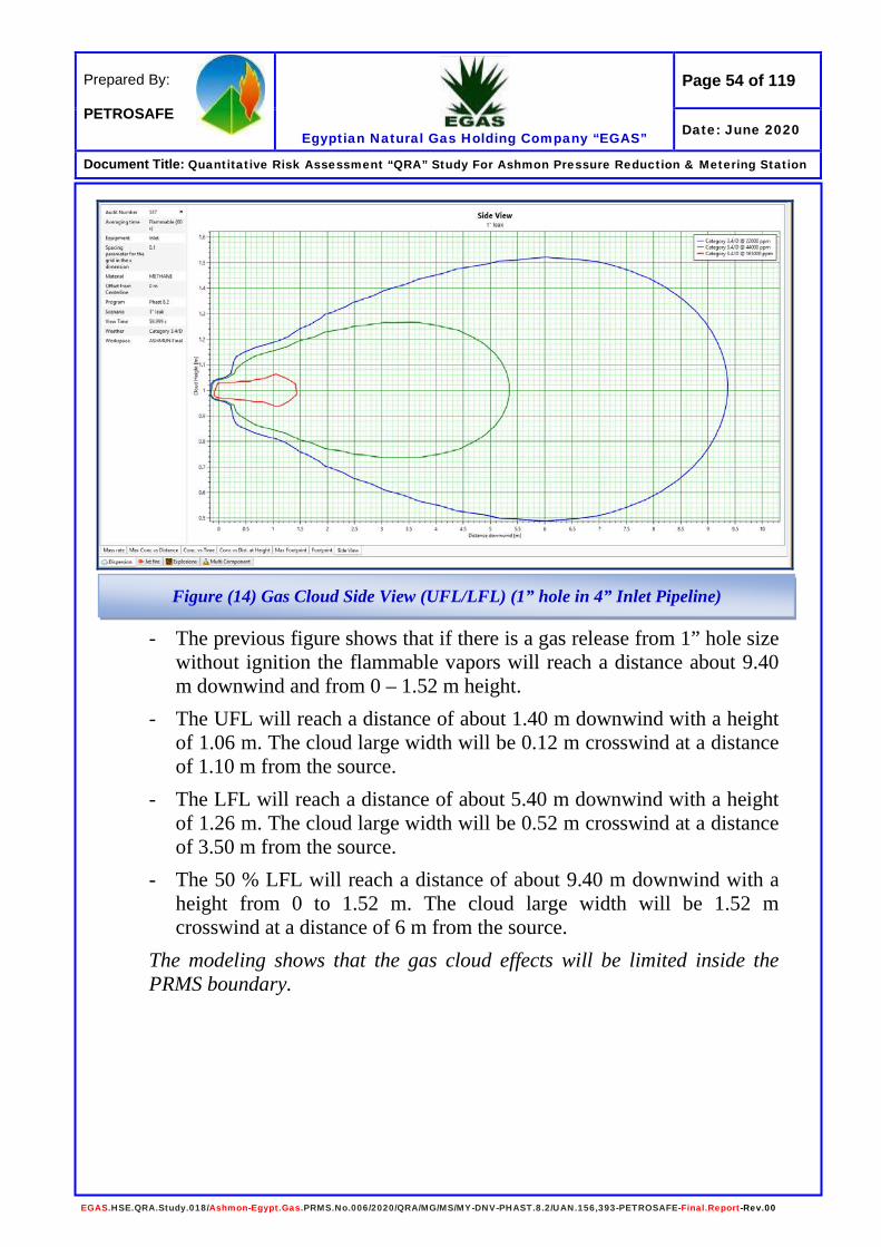
Page 54 of 119
Egyptian Natural Gas Holding Company “EGAS”
Prepared By: PETROSAFE
Date: June 2020
Document Title: Quantitative Risk Assessment “QRA” Study For Ashmon Pressure Reduction & Metering Station
EGAS.HSE.QRA.Study.018/Ashmon-Egypt.Gas.PRMS.No.006/2020/QRA/MG/MS/MY-DNV-PHAST.8.2/UAN.156,393-PETROSAFE-Final.Report-Rev.00
- The previous figure shows that if there is a gas release from 1” hole size without ignition the flammable vapors will reach a distance about 9.40 m downwind and from 0 – 1.52 m height.
- The UFL will reach a distance of about 1.40 m downwind with a height of 1.06 m. The cloud large width will be 0.12 m crosswind at a distance of 1.10 m from the source.
- The LFL will reach a distance of about 5.40 m downwind with a height of 1.26 m. The cloud large width will be 0.52 m crosswind at a distance of 3.50 m from the source.
- The 50 % LFL will reach a distance of about 9.40 m downwind with a height from 0 to 1.52 m. The cloud large width will be 1.52 m crosswind at a distance of 6 m from the source.
The modeling shows that the gas cloud effects will be limited inside the PRMS boundary.
Figure (14) Gas Cloud Side View (UFL/LFL) (1” hole in 4” Inlet Pipeline)

Page 55 of 119
Egyptian Natural Gas Holding Company “EGAS”
Prepared By: PETROSAFE
Date: June 2020
Document Title: Quantitative Risk Assessment “QRA” Study For Ashmon Pressure Reduction & Metering Station
EGAS.HSE.QRA.Study.018/Ashmon-Egypt.Gas.PRMS.No.006/2020/QRA/MG/MS/MY-DNV-PHAST.8.2/UAN.156,393-PETROSAFE-Final.Report-Rev.00
- The previous figure shows that if there is a gas release from 1” hole size and ignited the expected flame length is about 9.00 meters downwind.
- The 4 kW/m2 heat radiation contours extend about 11.30 meters downwind and 4.94 meters crosswind.
- The 9.5 kW/m2 heat radiation contours extend about 9.30 meters downwind and 2.37 meters crosswind.
- The 12.5 kW/m2 heat radiation contours extend about 8.80 meters downwind 1.64 meters crosswind.
- The 25 kW/m2 heat radiation not reached. The modeling shows that the heat radiation values will extend down and crosswind fence of the PRS boundary from the East side.
Figure (15) Heat Radiation Contours from Jet Fire (1” hole in 4” Inlet Pipeline)
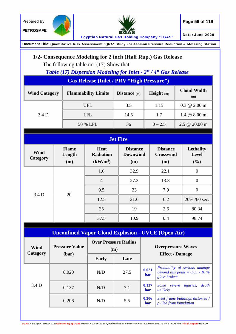
Page 56 of 119
Egyptian Natural Gas Holding Company “EGAS”
Prepared By: PETROSAFE
Date: June 2020
Document Title: Quantitative Risk Assessment “QRA” Study For Ashmon Pressure Reduction & Metering Station
EGAS.HSE.QRA.Study.018/Ashmon-Egypt.Gas.PRMS.No.006/2020/QRA/MG/MS/MY-DNV-PHAST.8.2/UAN.156,393-PETROSAFE-Final.Report-Rev.00
1/2- Consequence Modeling for 2 inch (Half Rup.) Gas Release The following table no. (17) Show that:
Table (17) Dispersion Modeling for Inlet - 2” / 4” Gas Release Gas Release (Inlet / PRV “High Pressure”)
Wind Category Flammability Limits Distance (m) Height (m) Cloud Width (m)
3.4 D
UFL 3.5 1.15 0.3 @ 2.00 m
LFL 14.5 1.7 1.4 @ 8.00 m
50 % LFL 36 0 – 2.5 2.5 @ 20.00 m
Jet Fire
Wind Category
Flame Length
(m)
Heat Radiation (kW/m2)
Distance Downwind
(m)
Distance Crosswind
(m)
Lethality Level (%)
3.4 D 20
1.6 32.9 22.1 0
4 27.3 13.8 0
9.5 23 7.9 0
12.5 21.6 6.2 20% /60 sec.
25 19 2.6 80.34
37.5 10.9 0.4 98.74
Unconfined Vapor Cloud Explosion - UVCE (Open Air)
Wind Category
Pressure Value (bar)
Over Pressure Radius (m) Overpressure Waves
Effect / Damage Early Late
3.4 D
0.020 N/D 27.5 0.021 bar
Probability of serious damage beyond this point = 0.05 - 10 % glass broken
0.137 N/D 7.1 0.137 bar
Some severe injuries, death unlikely
0.206 N/D 5.5 0.206 bar
Steel frame buildings distorted / pulled from foundation

Page 57 of 119
Egyptian Natural Gas Holding Company “EGAS”
Prepared By: PETROSAFE
Date: June 2020
Document Title: Quantitative Risk Assessment “QRA” Study For Ashmon Pressure Reduction & Metering Station
EGAS.HSE.QRA.Study.018/Ashmon-Egypt.Gas.PRMS.No.006/2020/QRA/MG/MS/MY-DNV-PHAST.8.2/UAN.156,393-PETROSAFE-Final.Report-Rev.00
- The previous figure shows that if there is a gas release from 2” hole size without ignition the flammable vapors will reach a distance about 36 m downwind and from 0 to 2.50 m height.
- The UFL will reach a distance of about 3.50 m downwind with a height of 1.15 m. The cloud large width will be 0.30 m crosswind at a distance of 2 m from the source.
- The LFL will reach a distance of about 14.50 m downwind with a height from 1.70 m. The cloud large width will be 1.40 m crosswind at a distance of 8 m from the source.
- The 50 % LFL will reach a distance of about 36 m downwind with a height from 0 to 2.50 m. The cloud large width will be 2.50 m crosswind at a distance of 20 m from the source.
The modeling shows that the gas cloud (50 % LFL) will extend to reach the southern fence and extend about outside. The UFL & LFL will be limited inside the PRS boundary.
Figure (16) Gas Cloud Side View (UFL/LFL) (2” hole in 4” Inlet Pipeline)

Page 58 of 119
Egyptian Natural Gas Holding Company “EGAS”
Prepared By: PETROSAFE
Date: June 2020
Document Title: Quantitative Risk Assessment “QRA” Study For Ashmon Pressure Reduction & Metering Station
EGAS.HSE.QRA.Study.018/Ashmon-Egypt.Gas.PRMS.No.006/2020/QRA/MG/MS/MY-DNV-PHAST.8.2/UAN.156,393-PETROSAFE-Final.Report-Rev.00
- The previous figure shows that if there is a gas release from 2” hole size and ignited the expected flame length is about 20 meters downwind.
- The 9.5 kW/m2 heat radiation contours extend about 23 meters downwind and 7.90 meters crosswind.
- The 12.5 kW/m2 heat radiation contours extend about 21.60 meters downwind and 6.20 meters crosswind.
- The 25 kW/m2 heat radiation contours extend about 19 meters downwind and 2.60 meters crosswind.
- The 37.5 kW/m2 heat radiation contours extend about 10.90 meters downwind and 0.40 meters crosswind.
The modeling shows that the values of 4, 9.5, 12.5 & 25 kW/m2 will extend outside the PRS southern fence downwind with no effects.
Figure (17) Heat Radiation Contours from Jet Fire (2” hole in 4” Inlet Pipeline)

Page 59 of 119
Egyptian Natural Gas Holding Company “EGAS”
Prepared By: PETROSAFE
Date: June 2020
Document Title: Quantitative Risk Assessment “QRA” Study For Ashmon Pressure Reduction & Metering Station
EGAS.HSE.QRA.Study.018/Ashmon-Egypt.Gas.PRMS.No.006/2020/QRA/MG/MS/MY-DNV-PHAST.8.2/UAN.156,393-PETROSAFE-Final.Report-Rev.00
- The previous figure shows that if there is a gas release from 2” hole size and late ignited this will give an explosion with different values of overpressure waves.
- The 0.020 bar overpressure waves will extend about 27.50 meters downwind.
- The 0.137 bar overpressure waves will extend about 7.10 meters downwind.
- The 0.206 bar overpressure waves will extend about 5.50 meters downwind.
The modeling shows that the value of 0.020, 0.137 & 0.206 bar will extend outside the PRMS south fence with no effects down or crosswind.
Figure (18) Late Explosion Overpressure Waves (2” hole in 4” Inlet Pipeline)

Page 60 of 119
Egyptian Natural Gas Holding Company “EGAS”
Prepared By: PETROSAFE
Date: June 2020
Document Title: Quantitative Risk Assessment “QRA” Study For Ashmon Pressure Reduction & Metering Station
EGAS.HSE.QRA.Study.018/Ashmon-Egypt.Gas.PRMS.No.006/2020/QRA/MG/MS/MY-DNV-PHAST.8.2/UAN.156,393-PETROSAFE-Final.Report-Rev.00
1/3- Consequence Modeling for 4 inch (Full Rupture) Gas Release The following table no. (18) Show that:
Table (18) Dispersion Modeling for Inlet - 4” Gas Release Gas Release
Wind Category Flammability Limits Distance (m) Height (m) Cloud Width (m)
3.4 D
UFL 8.5 1.4 0.8 @ 5.00 m
LFL 49 0 – 3.10 3.10 @ 30.00 m
50 % LFL 88 0 – 5.80 5.80 @ 65.00 m
Jet Fire
Wind Category
Flame Length
(m)
Heat Radiation (kW/m2)
Distance Downwind
(m)
Distance Crosswind
(m)
Lethality Level (%)
3.4 D 41.3
1.6 72.4 50 0 4 58.4 31.3 0
9.5 48.3 18.6 0 12.5 44.8 15.1 20 %/60 sec. 25 39.4 7.6 80.34
37.5 31.6 4.3 98.74
Unconfined Vapor Cloud Explosion - UVCE (Open Air)
Wind Category
Pressure Value (bar)
Over Pressure Radius (m) Overpressure Waves
Effect / Damage Early Late
3.4 D
0.020 N/D 81.7 0.021 bar
Probability of serious damage beyond this point = 0.05 - 10 % glass broken
0.137 N/D 17.7 0.137 bar
Some severe injuries, death unlikely
0.206 N/D 13.7 0.206 bar
Steel frame buildings distorted / pulled from foundation
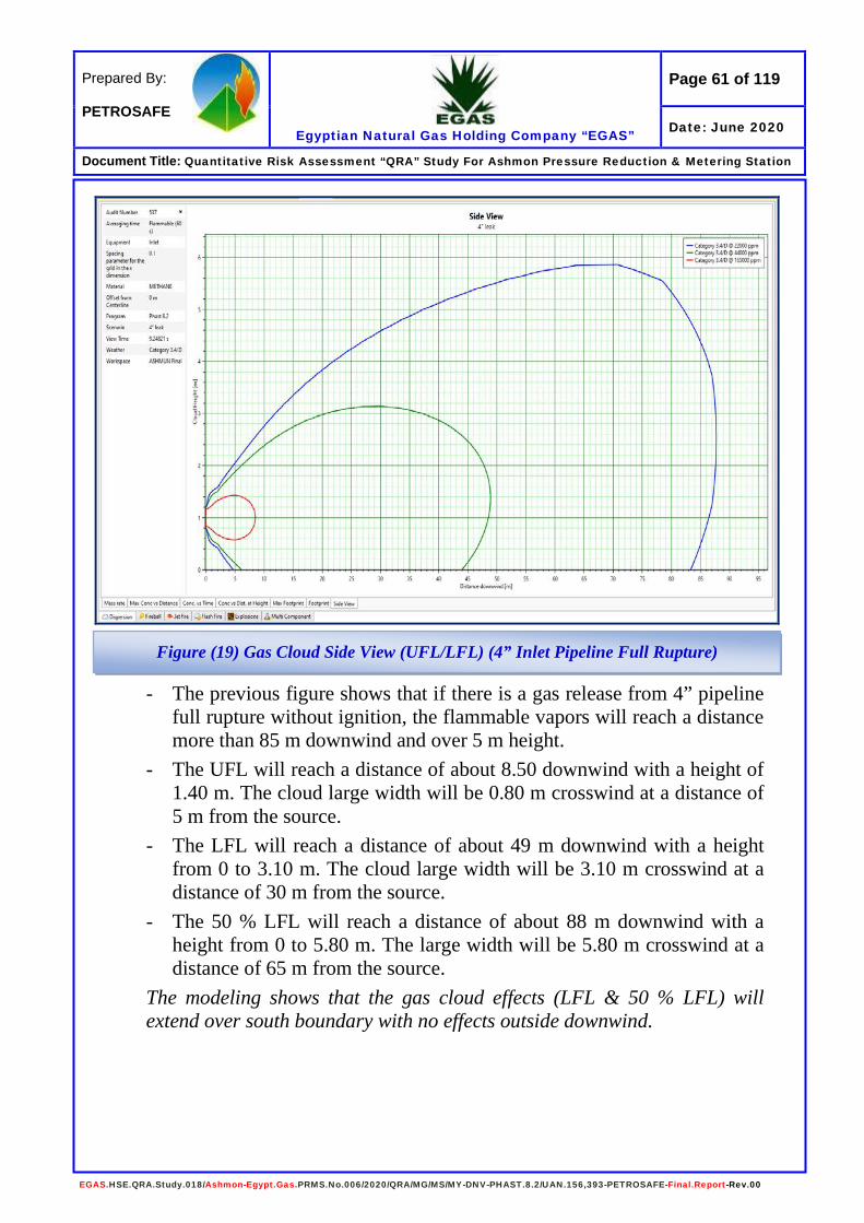
Page 61 of 119
Egyptian Natural Gas Holding Company “EGAS”
Prepared By: PETROSAFE
Date: June 2020
Document Title: Quantitative Risk Assessment “QRA” Study For Ashmon Pressure Reduction & Metering Station
EGAS.HSE.QRA.Study.018/Ashmon-Egypt.Gas.PRMS.No.006/2020/QRA/MG/MS/MY-DNV-PHAST.8.2/UAN.156,393-PETROSAFE-Final.Report-Rev.00
- The previous figure shows that if there is a gas release from 4” pipeline full rupture without ignition, the flammable vapors will reach a distance more than 85 m downwind and over 5 m height.
- The UFL will reach a distance of about 8.50 downwind with a height of 1.40 m. The cloud large width will be 0.80 m crosswind at a distance of 5 m from the source.
- The LFL will reach a distance of about 49 m downwind with a height from 0 to 3.10 m. The cloud large width will be 3.10 m crosswind at a distance of 30 m from the source.
- The 50 % LFL will reach a distance of about 88 m downwind with a height from 0 to 5.80 m. The large width will be 5.80 m crosswind at a distance of 65 m from the source.
The modeling shows that the gas cloud effects (LFL & 50 % LFL) will extend over south boundary with no effects outside downwind.
Figure (19) Gas Cloud Side View (UFL/LFL) (4” Inlet Pipeline Full Rupture)

Page 62 of 119
Egyptian Natural Gas Holding Company “EGAS”
Prepared By: PETROSAFE
Date: June 2020
Document Title: Quantitative Risk Assessment “QRA” Study For Ashmon Pressure Reduction & Metering Station
EGAS.HSE.QRA.Study.018/Ashmon-Egypt.Gas.PRMS.No.006/2020/QRA/MG/MS/MY-DNV-PHAST.8.2/UAN.156,393-PETROSAFE-Final.Report-Rev.00
- The previous figure shows that if there is a gas release from 4” pipeline full rupture and ignited the expected flame length is about 41.30 meters downwind.
- The 9.5 kW/m2 heat radiation contours extend about 48.30 meters downwind and 18.60 meters crosswind.
- The 12.5 kW/m2 heat radiation contours extend about 44.80 meters downwind and 15.10 meters crosswind.
- The 25 kW/m2 heat radiation contours extend about 39.40 meters downwind and 7.60 meters crosswind.
- The 37.5 kW/m2 heat radiation contours extend about 31.60 meters downwind and 4.30 meters crosswind.
The modeling shows that the heat radiation values 9.5, 12.5, 25 & 37.5 kW/m2 will extend outside the south fence with no effects downwind.
Figure (20) Heat Radiation Contours from Jet Fire (4” Inlet Pipeline Full Rupture)
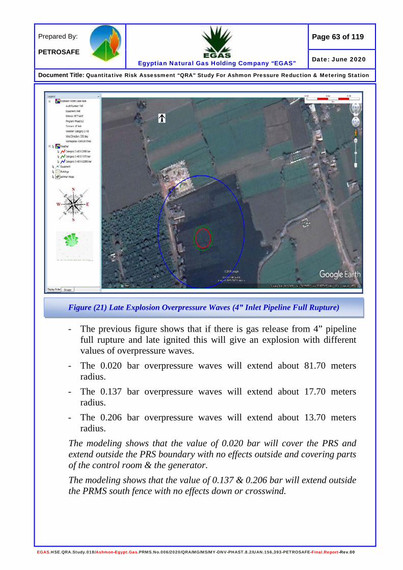
Page 63 of 119
Egyptian Natural Gas Holding Company “EGAS”
Prepared By: PETROSAFE
Date: June 2020
Document Title: Quantitative Risk Assessment “QRA” Study For Ashmon Pressure Reduction & Metering Station
EGAS.HSE.QRA.Study.018/Ashmon-Egypt.Gas.PRMS.No.006/2020/QRA/MG/MS/MY-DNV-PHAST.8.2/UAN.156,393-PETROSAFE-Final.Report-Rev.00
- The previous figure shows that if there is gas release from 4” pipeline full rupture and late ignited this will give an explosion with different values of overpressure waves.
- The 0.020 bar overpressure waves will extend about 81.70 meters radius.
- The 0.137 bar overpressure waves will extend about 17.70 meters radius.
- The 0.206 bar overpressure waves will extend about 13.70 meters radius.
The modeling shows that the value of 0.020 bar will cover the PRS and extend outside the PRS boundary with no effects outside and covering parts of the control room & the generator. The modeling shows that the value of 0.137 & 0.206 bar will extend outside the PRMS south fence with no effects down or crosswind.
Figure (21) Late Explosion Overpressure Waves (4” Inlet Pipeline Full Rupture)
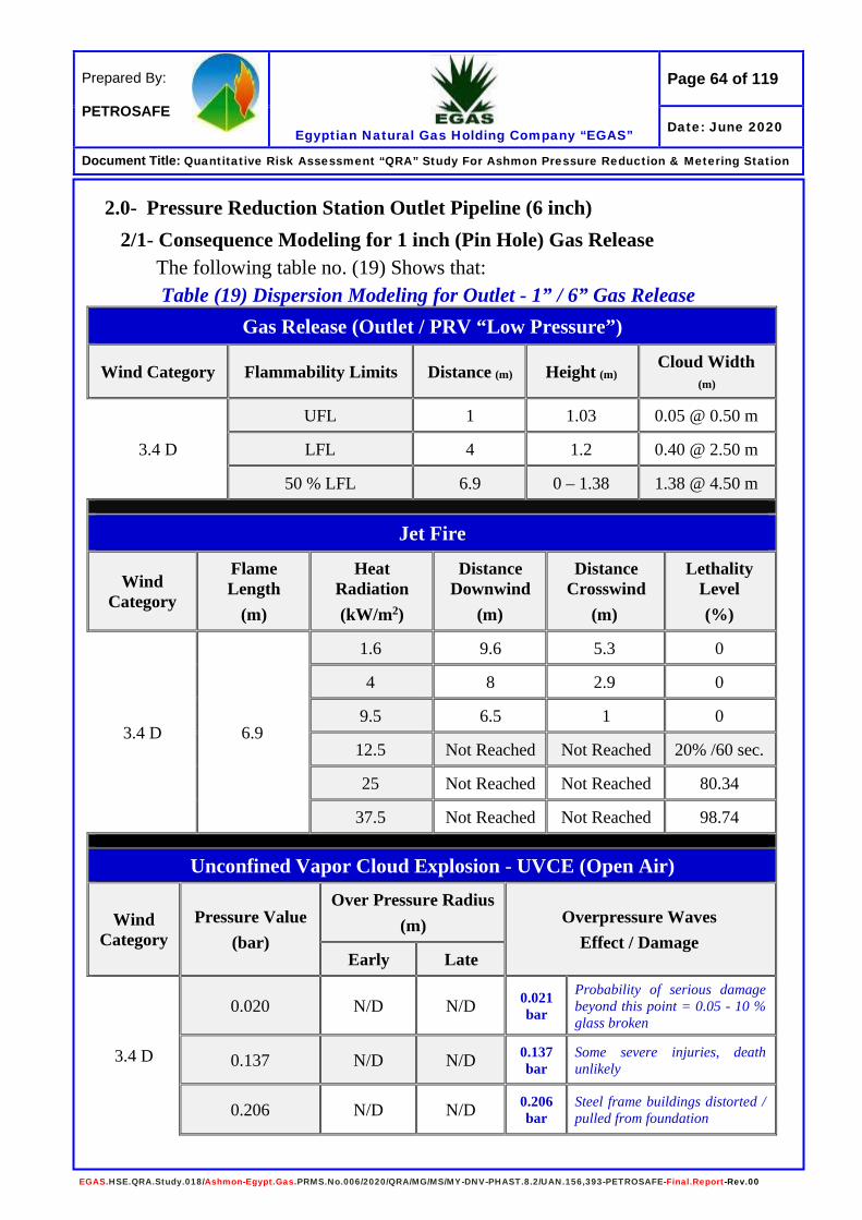
Page 64 of 119
Egyptian Natural Gas Holding Company “EGAS”
Prepared By: PETROSAFE
Date: June 2020
Document Title: Quantitative Risk Assessment “QRA” Study For Ashmon Pressure Reduction & Metering Station
EGAS.HSE.QRA.Study.018/Ashmon-Egypt.Gas.PRMS.No.006/2020/QRA/MG/MS/MY-DNV-PHAST.8.2/UAN.156,393-PETROSAFE-Final.Report-Rev.00
2.0- Pressure Reduction Station Outlet Pipeline (6 inch) 2/1- Consequence Modeling for 1 inch (Pin Hole) Gas Release
The following table no. (19) Shows that: Table (19) Dispersion Modeling for Outlet - 1” / 6” Gas Release
Gas Release (Outlet / PRV “Low Pressure”)
Wind Category Flammability Limits Distance (m) Height (m) Cloud Width (m)
3.4 D
UFL 1 1.03 0.05 @ 0.50 m
LFL 4 1.2 0.40 @ 2.50 m
50 % LFL 6.9 0 – 1.38 1.38 @ 4.50 m
Jet Fire
Wind Category
Flame Length
(m)
Heat Radiation (kW/m2)
Distance Downwind
(m)
Distance Crosswind
(m)
Lethality Level (%)
3.4 D 6.9
1.6 9.6 5.3 0
4 8 2.9 0
9.5 6.5 1 0
12.5 Not Reached Not Reached 20% /60 sec.
25 Not Reached Not Reached 80.34
37.5 Not Reached Not Reached 98.74
Unconfined Vapor Cloud Explosion - UVCE (Open Air)
Wind Category
Pressure Value (bar)
Over Pressure Radius (m) Overpressure Waves
Effect / Damage Early Late
3.4 D
0.020 N/D N/D 0.021 bar
Probability of serious damage beyond this point = 0.05 - 10 % glass broken
0.137 N/D N/D 0.137 bar
Some severe injuries, death unlikely
0.206 N/D N/D 0.206 bar
Steel frame buildings distorted / pulled from foundation
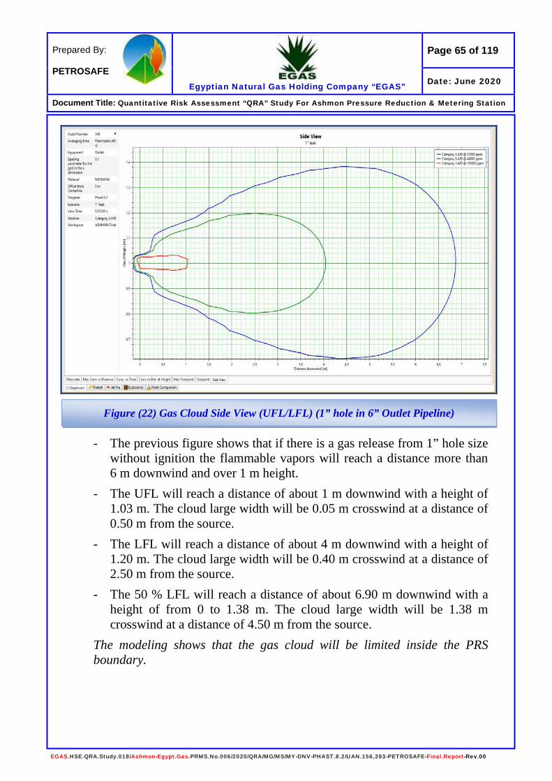
Page 65 of 119
Egyptian Natural Gas Holding Company “EGAS”
Prepared By: PETROSAFE
Date: June 2020
Document Title: Quantitative Risk Assessment “QRA” Study For Ashmon Pressure Reduction & Metering Station
EGAS.HSE.QRA.Study.018/Ashmon-Egypt.Gas.PRMS.No.006/2020/QRA/MG/MS/MY-DNV-PHAST.8.2/UAN.156,393-PETROSAFE-Final.Report-Rev.00
- The previous figure shows that if there is a gas release from 1” hole size without ignition the flammable vapors will reach a distance more than 6 m downwind and over 1 m height.
- The UFL will reach a distance of about 1 m downwind with a height of 1.03 m. The cloud large width will be 0.05 m crosswind at a distance of 0.50 m from the source.
- The LFL will reach a distance of about 4 m downwind with a height of 1.20 m. The cloud large width will be 0.40 m crosswind at a distance of 2.50 m from the source.
- The 50 % LFL will reach a distance of about 6.90 m downwind with a height of from 0 to 1.38 m. The cloud large width will be 1.38 m crosswind at a distance of 4.50 m from the source.
The modeling shows that the gas cloud will be limited inside the PRS boundary.
Figure (22) Gas Cloud Side View (UFL/LFL) (1” hole in 6” Outlet Pipeline)

Page 66 of 119
Egyptian Natural Gas Holding Company “EGAS”
Prepared By: PETROSAFE
Date: June 2020
Document Title: Quantitative Risk Assessment “QRA” Study For Ashmon Pressure Reduction & Metering Station
EGAS.HSE.QRA.Study.018/Ashmon-Egypt.Gas.PRMS.No.006/2020/QRA/MG/MS/MY-DNV-PHAST.8.2/UAN.156,393-PETROSAFE-Final.Report-Rev.00
- The previous figure shows that if there is a gas release from 1” hole size and ignited the expected flame length is about 6.90 meters downwind.
- The 1.6 kW/m2 heat radiation contours extend about 9.60 meters downwind and 5.30 meters crosswind.
- The 4 kW/m2 heat radiation contours extend about 8 meters downwind and 2.90 meters crosswind.
- The 9.5 kW/m2 heat radiation contours extend about 6.50 meters downwind and 1 meters crosswind.
- The 12.5 kW/m2 heat radiation not reached. - The 25 kW/m2 heat radiation not reached. - The 37.5 kW/m2 heat radiation not reached. The modeling shows that the heat radiation value 1.6, 4 & 9.5 kW/m2 effects will be limited inside the PRS boundary with no effects. The values of 12.5, 25 & 37.5 kW/m2 not determined by the software due to small leakage.
Figure (23) Heat Radiation Contours from Jet Fire (1” hole in 6” Outlet Pipeline)

Page 67 of 119
Egyptian Natural Gas Holding Company “EGAS”
Prepared By: PETROSAFE
Date: June 2020
Document Title: Quantitative Risk Assessment “QRA” Study For Ashmon Pressure Reduction & Metering Station
EGAS.HSE.QRA.Study.018/Ashmon-Egypt.Gas.PRMS.No.006/2020/QRA/MG/MS/MY-DNV-PHAST.8.2/UAN.156,393-PETROSAFE-Final.Report-Rev.00
2/2- Consequence Modeling for 3 inch (Half Rup.) Gas Release The following table no. (20) Show that: Table (20) Dispersion Modeling for Outlet - 3” / 6” Gas Release
Gas Release
Wind Category Flammability Limits Distance (m) Height (m) Cloud Width (m)
3.4 D
UFL 3.25 1.15 0.3 @ 2.00 m
LFL 11.4 1.65 1.30 @ 8.00 m
50 % LFL 13.8 0 – 2.15 2.15 @ 10.40 m
Jet Fire
Wind Category
Flame Length
(m)
Heat Radiation (kW/m2)
Distance Downwind
(m)
Distance Crosswind
(m)
Lethality Level (%)
3.4 D 23.1
1.6 38.1 25.5 0
4 31.4 16 0
9.5 26.6 9.2 0
12.5 25 7.4 20% /60 sec.
25 22 3.2 80.34
37.5 15 1.3 98.74
Unconfined Vapor Cloud Explosion - UVCE (Open Air)
Wind Category
Pressure Value (bar)
Over Pressure Radius (m) Overpressure Waves
Effect / Damage Early Late
3.4 D
0.020 N/D 23.75 0.021 bar
Probability of serious damage beyond this point = 0.05 - 10 % glass broken
0.137 N/D 2.7 0.137 bar
Some severe injuries, death unlikely
0.206 N/D 2 0.206 bar
Steel frame buildings distorted / pulled from foundation
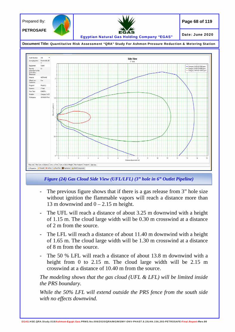
Page 68 of 119
Egyptian Natural Gas Holding Company “EGAS”
Prepared By: PETROSAFE
Date: June 2020
Document Title: Quantitative Risk Assessment “QRA” Study For Ashmon Pressure Reduction & Metering Station
EGAS.HSE.QRA.Study.018/Ashmon-Egypt.Gas.PRMS.No.006/2020/QRA/MG/MS/MY-DNV-PHAST.8.2/UAN.156,393-PETROSAFE-Final.Report-Rev.00
- The previous figure shows that if there is a gas release from 3” hole size without ignition the flammable vapors will reach a distance more than 13 m downwind and 0 – 2.15 m height.
- The UFL will reach a distance of about 3.25 m downwind with a height of 1.15 m. The cloud large width will be 0.30 m crosswind at a distance of 2 m from the source.
- The LFL will reach a distance of about 11.40 m downwind with a height of 1.65 m. The cloud large width will be 1.30 m crosswind at a distance of 8 m from the source.
- The 50 % LFL will reach a distance of about 13.8 m downwind with a height from 0 to 2.15 m. The cloud large width will be 2.15 m crosswind at a distance of 10.40 m from the source.
The modeling shows that the gas cloud (UFL & LFL) will be limited inside the PRS boundary. While the 50% LFL will extend outside the PRS fence from the south side with no effects downwind.
Figure (24) Gas Cloud Side View (UFL/LFL) (3” hole in 6” Outlet Pipeline)
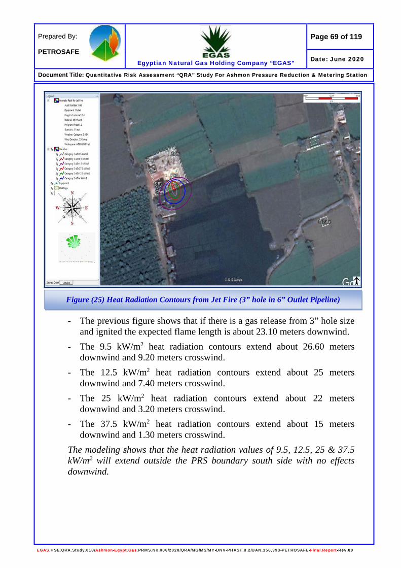
Page 69 of 119
Egyptian Natural Gas Holding Company “EGAS”
Prepared By: PETROSAFE
Date: June 2020
Document Title: Quantitative Risk Assessment “QRA” Study For Ashmon Pressure Reduction & Metering Station
EGAS.HSE.QRA.Study.018/Ashmon-Egypt.Gas.PRMS.No.006/2020/QRA/MG/MS/MY-DNV-PHAST.8.2/UAN.156,393-PETROSAFE-Final.Report-Rev.00
- The previous figure shows that if there is a gas release from 3” hole size and ignited the expected flame length is about 23.10 meters downwind.
- The 9.5 kW/m2 heat radiation contours extend about 26.60 meters downwind and 9.20 meters crosswind.
- The 12.5 kW/m2 heat radiation contours extend about 25 meters downwind and 7.40 meters crosswind.
- The 25 kW/m2 heat radiation contours extend about 22 meters downwind and 3.20 meters crosswind.
- The 37.5 kW/m2 heat radiation contours extend about 15 meters downwind and 1.30 meters crosswind.
The modeling shows that the heat radiation values of 9.5, 12.5, 25 & 37.5 kW/m2 will extend outside the PRS boundary south side with no effects downwind.
Figure (25) Heat Radiation Contours from Jet Fire (3” hole in 6” Outlet Pipeline)

Page 70 of 119
Egyptian Natural Gas Holding Company “EGAS”
Prepared By: PETROSAFE
Date: June 2020
Document Title: Quantitative Risk Assessment “QRA” Study For Ashmon Pressure Reduction & Metering Station
EGAS.HSE.QRA.Study.018/Ashmon-Egypt.Gas.PRMS.No.006/2020/QRA/MG/MS/MY-DNV-PHAST.8.2/UAN.156,393-PETROSAFE-Final.Report-Rev.00
- The previous figure shows that if there is a gas release from 3” hole size and late ignited this will give an explosion with different values of overpressure waves.
- The 0.020 bar overpressure waves will extend about 23.75 meters radius.
- The 0.137 bar overpressure waves will extend about 2.70 meters radius.
- The 0.206 bar overpressure waves will extend about 2 meters radius.
The modeling shows that the value of 0.020 bar will cover the PRS and extend outside the PRS boundary with no effects outside and covering parts of the control room & the generator. The values of 0.137 & 0.206 bar will be extended outside the PRS boundary with no effect down or crosswind.
Figure (26) Late Explosion Overpressure Waves (3” hole in 6” Outlet Pipeline)

Page 71 of 119
Egyptian Natural Gas Holding Company “EGAS”
Prepared By: PETROSAFE
Date: June 2020
Document Title: Quantitative Risk Assessment “QRA” Study For Ashmon Pressure Reduction & Metering Station
EGAS.HSE.QRA.Study.018/Ashmon-Egypt.Gas.PRMS.No.006/2020/QRA/MG/MS/MY-DNV-PHAST.8.2/UAN.156,393-PETROSAFE-Final.Report-Rev.00
2/3- Consequence Modeling for 6 inch (Full Rup.) Gas Release The following table no. (21) Show that:
Table (21) Dispersion Modeling for Outlet - 6” Gas Release Gas Release
Wind Category Flammability Limits Distance (m) Height (m) Cloud Width (m)
3.4 D UFL 4.1 1.2 0.4 @ 2.00 m LFL 8.3 1.7 1.4 @ 6.00 m
50 % LFL 9.1 0 – 1.95 1.95 @ 7.00 m
Jet Fire
Wind Category
Flame Length
(m)
Heat Radiation (kW/m2)
Distance Downwind
(m)
Distance Crosswind
(m)
Lethality Level (%)
3.4 D 44.5
1.6 78 53.6 0 4 63 33.6 0
9.5 52 20.1 0 12.5 48.2 16.3 20% /60 sec. 25 42.5 8.3 80.34
37.5 34.4 4.8 98.74
Unconfined Vapor Cloud Explosion - UVCE (Open Air)
Wind Category
Pressure Value (bar)
Over Pressure Radius (m) Overpressure Waves
Effect / Damage Early Late
3.4 D
0.020 N/D 32.4 0.021 bar
Probability of serious damage beyond this point = 0.05 - 10 % glass broken
0.137 N/D 8.4 0.137 bar
Some severe injuries, death unlikely
0.206 N/D 6.5 0.206 bar
Steel frame buildings distorted / pulled from foundation
Fireball Wind
Category Heat Radiation
(kW/m2) Distance
(m) Heat Radiation (kW/m2) Effects
on People & Structures
3.4 D
4 20 12.5
20 % Chance of fatality for 60 sec exposure
25 100 % Chance of fatality for continuous exposure 50 % Chance of fatality for 30 sec exposure
37.5 Sufficient of cause process equipment damage
12.5 11
37.5 5.4

Page 72 of 119
Egyptian Natural Gas Holding Company “EGAS”
Prepared By: PETROSAFE
Date: June 2020
Document Title: Quantitative Risk Assessment “QRA” Study For Ashmon Pressure Reduction & Metering Station
EGAS.HSE.QRA.Study.018/Ashmon-Egypt.Gas.PRMS.No.006/2020/QRA/MG/MS/MY-DNV-PHAST.8.2/UAN.156,393-PETROSAFE-Final.Report-Rev.00
- The previous figure shows that if there is a gas release from 6” pipeline full rupture without ignition the flammable vapors will reach a distance more than 9 m downwind and from 0 to 1.95 m height.
- The UFL will reach a distance of about 4.10 m downwind with a height of 1.20 m. The cloud large width will be 0.4 m crosswind at a distance of 2 m from the source.
- The LFL will reach a distance of about 8.30 m downwind with a height of 1.70 m. The cloud large width will be 1.40 m crosswind at a distance of 6 m from the source.
- The 50 % LFL will reach a distance of about 9.10 m downwind with a height from 0 to 1.95 m. The cloud large width will be 1.95 m crosswind at a distance of 7 m from the source.
The modeling shows that the gas cloud effects will be limited inside the PRS boundary.
Figure (27) Gas Cloud Side View (UFL/LFL) (6” Outlet Pipeline Full Rupture)

Page 73 of 119
Egyptian Natural Gas Holding Company “EGAS”
Prepared By: PETROSAFE
Date: June 2020
Document Title: Quantitative Risk Assessment “QRA” Study For Ashmon Pressure Reduction & Metering Station
EGAS.HSE.QRA.Study.018/Ashmon-Egypt.Gas.PRMS.No.006/2020/QRA/MG/MS/MY-DNV-PHAST.8.2/UAN.156,393-PETROSAFE-Final.Report-Rev.00
- The previous figure shows that if there is a gas release from 6” pipeline full rupture and ignited the expected flame length is about 44.50 meters downwind.
- The 9.5 kW/m2 heat radiation contours extend about 52 meters downwind and 20.10 meters crosswind.
- The 12.5 kW/m2 heat radiation contours extend about 48.20 meters downwind and 16.30 meters crosswind.
- The 25 kW/m2 heat radiation contours extend about 42.50 meters downwind and 8.30 meters crosswind.
- The 37.5 kW/m2 heat radiation contours extend about 34.40 meters downwind and 4.80 meters crosswind.
The modeling shows that the heat radiation values 9.5, 12.5, 25 & 37.5 kW/m2 will extend outside the south fence with no effects down and crosswind.
Figure (28) Heat Radiation Contours from Jet Fire (6” Outlet Pipeline Full Rupture)
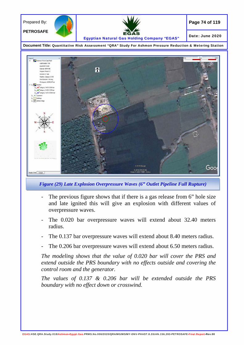
Page 74 of 119
Egyptian Natural Gas Holding Company “EGAS”
Prepared By: PETROSAFE
Date: June 2020
Document Title: Quantitative Risk Assessment “QRA” Study For Ashmon Pressure Reduction & Metering Station
EGAS.HSE.QRA.Study.018/Ashmon-Egypt.Gas.PRMS.No.006/2020/QRA/MG/MS/MY-DNV-PHAST.8.2/UAN.156,393-PETROSAFE-Final.Report-Rev.00
- The previous figure shows that if there is a gas release from 6” hole size and late ignited this will give an explosion with different values of overpressure waves.
- The 0.020 bar overpressure waves will extend about 32.40 meters radius.
- The 0.137 bar overpressure waves will extend about 8.40 meters radius.
- The 0.206 bar overpressure waves will extend about 6.50 meters radius.
The modeling shows that the value of 0.020 bar will cover the PRS and extend outside the PRS boundary with no effects outside and covering the control room and the generator. The values of 0.137 & 0.206 bar will be extended outside the PRS boundary with no effect down or crosswind.
Figure (29) Late Explosion Overpressure Waves (6” Outlet Pipeline Full Rupture)
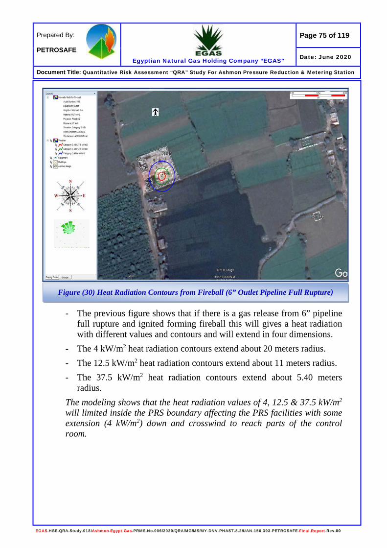
Page 75 of 119
Egyptian Natural Gas Holding Company “EGAS”
Prepared By: PETROSAFE
Date: June 2020
Document Title: Quantitative Risk Assessment “QRA” Study For Ashmon Pressure Reduction & Metering Station
EGAS.HSE.QRA.Study.018/Ashmon-Egypt.Gas.PRMS.No.006/2020/QRA/MG/MS/MY-DNV-PHAST.8.2/UAN.156,393-PETROSAFE-Final.Report-Rev.00
- The previous figure shows that if there is a gas release from 6” pipeline full rupture and ignited forming fireball this will gives a heat radiation with different values and contours and will extend in four dimensions.
- The 4 kW/m2 heat radiation contours extend about 20 meters radius. - The 12.5 kW/m2 heat radiation contours extend about 11 meters radius. - The 37.5 kW/m2 heat radiation contours extend about 5.40 meters
radius. The modeling shows that the heat radiation values of 4, 12.5 & 37.5 kW/m2 will limited inside the PRS boundary affecting the PRS facilities with some extension (4 kW/m2) down and crosswind to reach parts of the control room.
Figure (30) Heat Radiation Contours from Fireball (6” Outlet Pipeline Full Rupture)
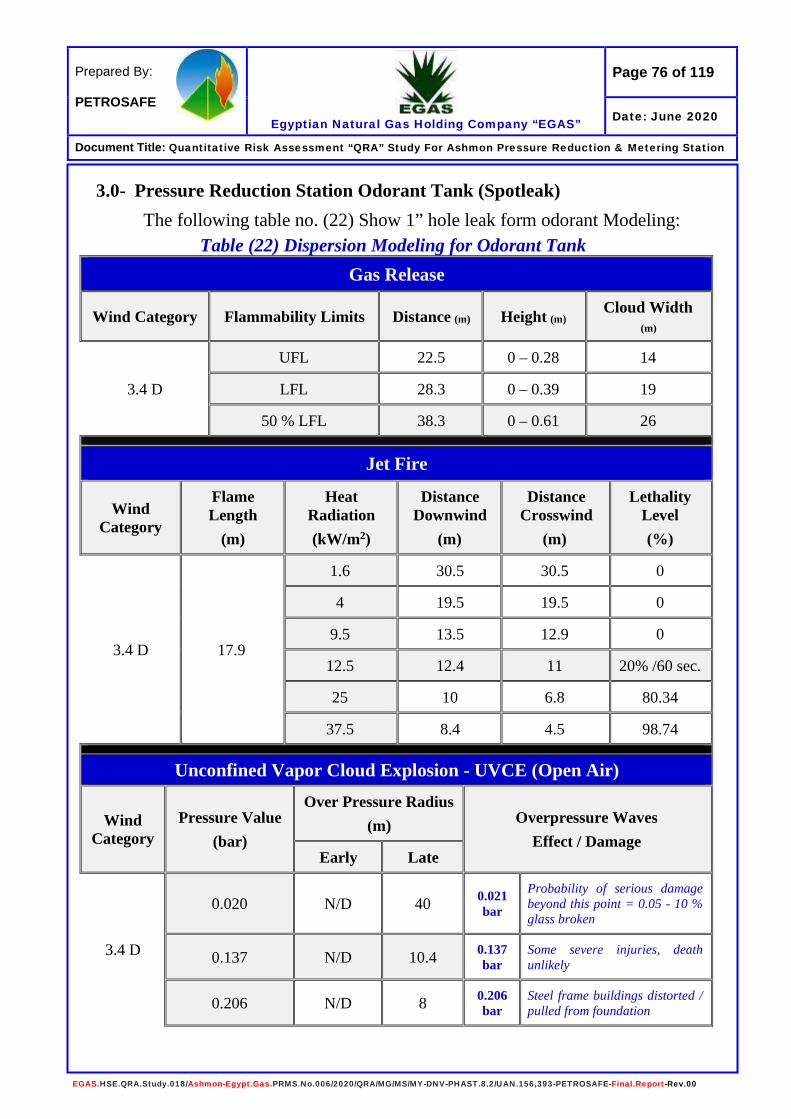
Page 76 of 119
Egyptian Natural Gas Holding Company “EGAS”
Prepared By: PETROSAFE
Date: June 2020
Document Title: Quantitative Risk Assessment “QRA” Study For Ashmon Pressure Reduction & Metering Station
EGAS.HSE.QRA.Study.018/Ashmon-Egypt.Gas.PRMS.No.006/2020/QRA/MG/MS/MY-DNV-PHAST.8.2/UAN.156,393-PETROSAFE-Final.Report-Rev.00
3.0- Pressure Reduction Station Odorant Tank (Spotleak) The following table no. (22) Show 1” hole leak form odorant Modeling:
Table (22) Dispersion Modeling for Odorant Tank Gas Release
Wind Category Flammability Limits Distance (m) Height (m) Cloud Width (m)
3.4 D
UFL 22.5 0 – 0.28 14
LFL 28.3 0 – 0.39 19
50 % LFL 38.3 0 – 0.61 26
Jet Fire
Wind Category
Flame Length
(m)
Heat Radiation (kW/m2)
Distance Downwind
(m)
Distance Crosswind
(m)
Lethality Level (%)
3.4 D 17.9
1.6 30.5 30.5 0
4 19.5 19.5 0
9.5 13.5 12.9 0
12.5 12.4 11 20% /60 sec.
25 10 6.8 80.34
37.5 8.4 4.5 98.74
Unconfined Vapor Cloud Explosion - UVCE (Open Air)
Wind Category
Pressure Value (bar)
Over Pressure Radius (m) Overpressure Waves
Effect / Damage Early Late
3.4 D
0.020 N/D 40 0.021 bar
Probability of serious damage beyond this point = 0.05 - 10 % glass broken
0.137 N/D 10.4 0.137 bar
Some severe injuries, death unlikely
0.206 N/D 8 0.206 bar
Steel frame buildings distorted / pulled from foundation
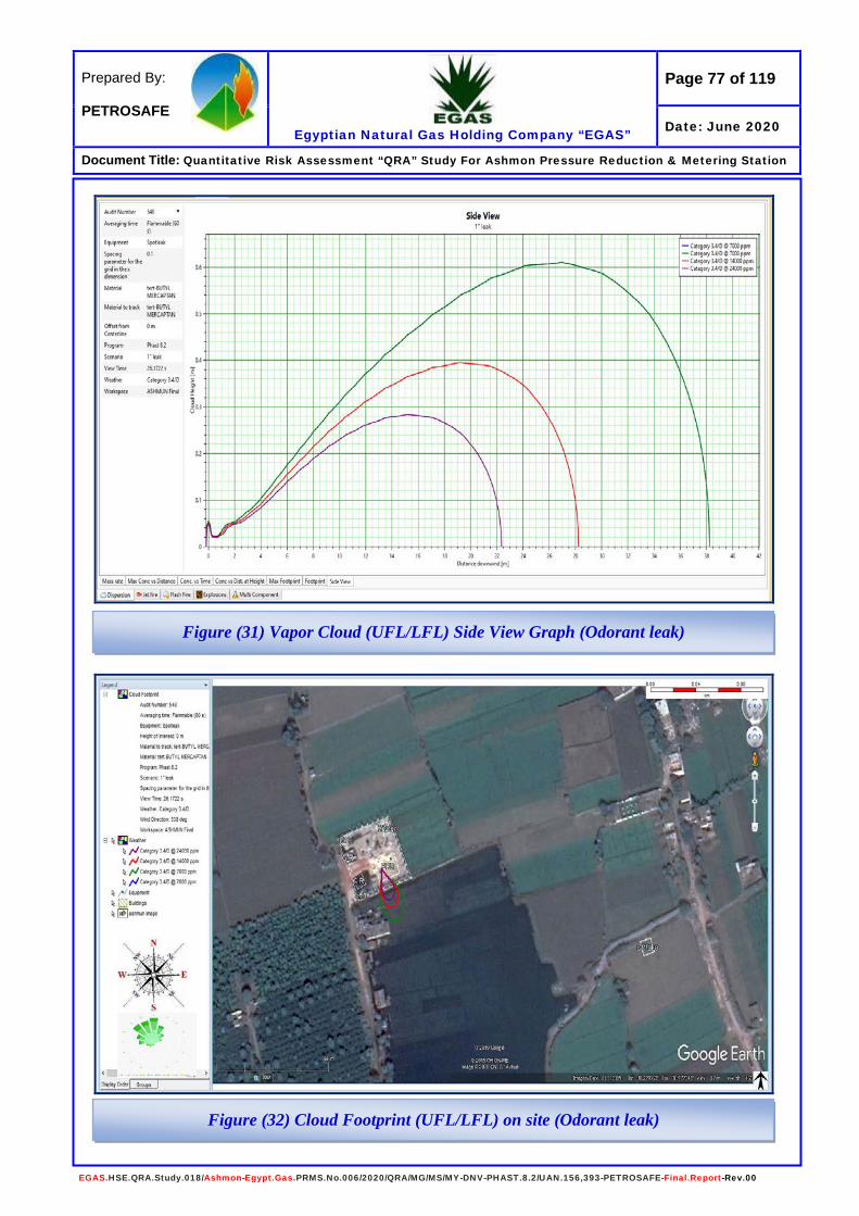
Page 77 of 119
Egyptian Natural Gas Holding Company “EGAS”
Prepared By: PETROSAFE
Date: June 2020
Document Title: Quantitative Risk Assessment “QRA” Study For Ashmon Pressure Reduction & Metering Station
EGAS.HSE.QRA.Study.018/Ashmon-Egypt.Gas.PRMS.No.006/2020/QRA/MG/MS/MY-DNV-PHAST.8.2/UAN.156,393-PETROSAFE-Final.Report-Rev.00
Figure (31) Vapor Cloud (UFL/LFL) Side View Graph (Odorant leak)
Figure (32) Cloud Footprint (UFL/LFL) on site (Odorant leak)

Page 78 of 119
Egyptian Natural Gas Holding Company “EGAS”
Prepared By: PETROSAFE
Date: June 2020
Document Title: Quantitative Risk Assessment “QRA” Study For Ashmon Pressure Reduction & Metering Station
EGAS.HSE.QRA.Study.018/Ashmon-Egypt.Gas.PRMS.No.006/2020/QRA/MG/MS/MY-DNV-PHAST.8.2/UAN.156,393-PETROSAFE-Final.Report-Rev.00
- The previous figures show that if there is a leak from odorant tank without ignition the flammable vapors will reach a distance more than 38 m downwind and from 0 to 0.61 m height (the vapors heavier than air).
- The UFL (2.4E+04 ppm) will reach a distance of about 22.50 m downwind with a height from 0 to 0.28 m. The cloud large width will be 14 m crosswind.
- The LFL (1.4E+04 ppm) will reach a distance of about 28.30 m downwind with a height from 0 to 0.39 m. The cloud large width will be 19 m crosswind.
- The 50 % LFL (7000 ppm) will reach a distance of about 38.30 m downwind with a height from 0 to 0.61 m. The cloud large width will be 26 m crosswind.
The modeling shows that the vapor cloud will extend outside the PRS fence from the south side with no effects downwind. Consideration should be taken when deal with liquid, vapors and smokes according to the MSDS for the material.

Page 79 of 119
Egyptian Natural Gas Holding Company “EGAS”
Prepared By: PETROSAFE
Date: June 2020
Document Title: Quantitative Risk Assessment “QRA” Study For Ashmon Pressure Reduction & Metering Station
EGAS.HSE.QRA.Study.018/Ashmon-Egypt.Gas.PRMS.No.006/2020/QRA/MG/MS/MY-DNV-PHAST.8.2/UAN.156,393-PETROSAFE-Final.Report-Rev.00
Figure (33) Heat Radiation Contours - Jet Fire Graph (Odorant Leak)
Figure (34) Heat Radiation Contours - Jet Fire on Site (Odorant Leak)

Page 80 of 119
Egyptian Natural Gas Holding Company “EGAS”
Prepared By: PETROSAFE
Date: June 2020
Document Title: Quantitative Risk Assessment “QRA” Study For Ashmon Pressure Reduction & Metering Station
EGAS.HSE.QRA.Study.018/Ashmon-Egypt.Gas.PRMS.No.006/2020/QRA/MG/MS/MY-DNV-PHAST.8.2/UAN.156,393-PETROSAFE-Final.Report-Rev.00
- The previous figures show that if there is a leak from the odorant tank and ignited the expected flame length is about 17.90 meters downwind.
- The 9.5 kW/m2 heat radiation contours extend about 13.50 meters downwind and 12.90 meters crosswind.
- The 12.5 kW/m2 heat radiation contours extend about 12.40 meters downwind and 11 meters crosswind.
- The 25 kW/m2 heat radiation contours extend about 10 meters downwind and 6.80 meters crosswind.
- The 37.5 kW/m2 heat radiation contours extend about 8.40 meters downwind and 4.50 meters crosswind.
The modeling shows that all values of heat radiation 9.5, 12.5, 25 & 37.5 kW/m2 will be limited inside the PRS boundary down and crosswind.

Page 81 of 119
Egyptian Natural Gas Holding Company “EGAS”
Prepared By: PETROSAFE
Date: June 2020
Document Title: Quantitative Risk Assessment “QRA” Study For Ashmon Pressure Reduction & Metering Station
EGAS.HSE.QRA.Study.018/Ashmon-Egypt.Gas.PRMS.No.006/2020/QRA/MG/MS/MY-DNV-PHAST.8.2/UAN.156,393-PETROSAFE-Final.Report-Rev.00
Figure (35) Late Explosion Overpressure Waves Graph (Odorant Leak)
Figure (36) Late Explosion Overpressure Waves on Site (Odorant Leak)
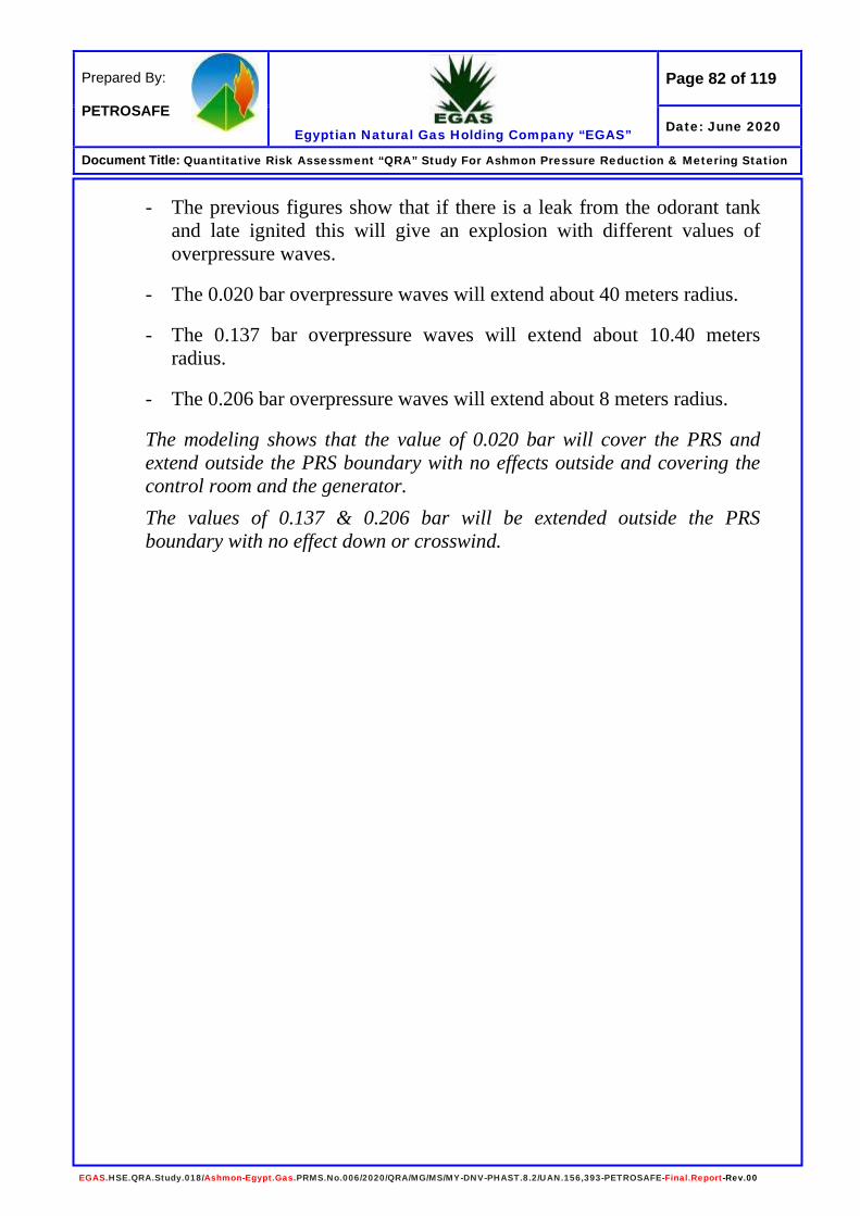
Page 82 of 119
Egyptian Natural Gas Holding Company “EGAS”
Prepared By: PETROSAFE
Date: June 2020
Document Title: Quantitative Risk Assessment “QRA” Study For Ashmon Pressure Reduction & Metering Station
EGAS.HSE.QRA.Study.018/Ashmon-Egypt.Gas.PRMS.No.006/2020/QRA/MG/MS/MY-DNV-PHAST.8.2/UAN.156,393-PETROSAFE-Final.Report-Rev.00
- The previous figures show that if there is a leak from the odorant tank and late ignited this will give an explosion with different values of overpressure waves.
- The 0.020 bar overpressure waves will extend about 40 meters radius.
- The 0.137 bar overpressure waves will extend about 10.40 meters radius.
- The 0.206 bar overpressure waves will extend about 8 meters radius.
The modeling shows that the value of 0.020 bar will cover the PRS and extend outside the PRS boundary with no effects outside and covering the control room and the generator. The values of 0.137 & 0.206 bar will be extended outside the PRS boundary with no effect down or crosswind.

Page 83 of 119
Egyptian Natural Gas Holding Company “EGAS”
Prepared By: PETROSAFE
Date: June 2020
Document Title: Quantitative Risk Assessment “QRA” Study For Ashmon Pressure Reduction & Metering Station
EGAS.HSE.QRA.Study.018/Ashmon-Egypt.Gas.PRMS.No.006/2020/QRA/MG/MS/MY-DNV-PHAST.8.2/UAN.156,393-PETROSAFE-Final.Report-Rev.00
4.0- Gas Heater (Water Bath Heating System) The following table no. (23) Show 1” hole leak form the heater Modeling:
Table (23) Dispersion Modeling for Heater Tank Gas Release
Wind Category Flammability Limits Distance (m) Height (m) Cloud Width (m)
3.4 D
UFL 2 2.08 0.30 @ 1.00 m
LFL 7.5 2.35 0.70 @ 4.00 m
50 % LFL 12.6 0 – 2.7 2.70 @ 8.00 m
Jet Fire
Wind Category
Flame Length
(m)
Heat Radiation (kW/m2)
Distance Downwind
(m)
Distance Crosswind
(m)
Lethality Level (%)
3.4 D 11.9
1.6 18.7 12 0
4 15.2 7 0
9.5 12 3.3 0
12.5 11.2 2 20% /60 sec.
25 Not Reached Not Reached 80.34
37.5 Not Reached Not Reached 98.74
Unconfined Vapor Cloud Explosion - UVCE (Open Air)
Wind Category
Pressure Value (bar)
Over Pressure Radius (m) Overpressure Waves
Effect / Damage
Early Late
3.4 D
0.020 N/D 14.7 0.021 bar
Probability of serious damage beyond this point = 0.05 - 10 % glass broken
0.137 N/D 3.8 0.137 bar
Some severe injuries, death unlikely
0.206 N/D 3 0.206 bar
Steel frame buildings distorted / pulled from foundation

Page 84 of 119
Egyptian Natural Gas Holding Company “EGAS”
Prepared By: PETROSAFE
Date: June 2020
Document Title: Quantitative Risk Assessment “QRA” Study For Ashmon Pressure Reduction & Metering Station
EGAS.HSE.QRA.Study.018/Ashmon-Egypt.Gas.PRMS.No.006/2020/QRA/MG/MS/MY-DNV-PHAST.8.2/UAN.156,393-PETROSAFE-Final.Report-Rev.00
- The previous figure shows that if there is a gas release from heater pipe without ignition the flammable vapors will reach a distance about 12.60 m downwind and from 0 to 2.70 m height.
- The UFL will reach a distance of about 2 m downwind with a height of 2.08 m. The cloud large width will be 0.30 m.
- The LFL will reach a distance of about 7.50 m downwind with a height of 2.35 m. The cloud large width will be 0.70 m.
- The 50 % LFL will reach a distance of about 12.60 m downwind with a height from 0 to 2.70 m. The cloud large width will be 2.70 m.
The modeling shows that the vapor cloud will extend inside the PRS boundary downwind.
Figure (37) Vapor Cloud (UFL/LFL) Side View Graph (Gas Heater)

Page 85 of 119
Egyptian Natural Gas Holding Company “EGAS”
Prepared By: PETROSAFE
Date: June 2020
Document Title: Quantitative Risk Assessment “QRA” Study For Ashmon Pressure Reduction & Metering Station
EGAS.HSE.QRA.Study.018/Ashmon-Egypt.Gas.PRMS.No.006/2020/QRA/MG/MS/MY-DNV-PHAST.8.2/UAN.156,393-PETROSAFE-Final.Report-Rev.00
Figure (38) Heat Radiation Contours - Fire Graph (Gas Heater)
Figure (39) Heat Radiation Contours - Fire on Site (Gas Heater)
Page 86 of 119
Egyptian Natural Gas Holding Company “EGAS”
Prepared By: PETROSAFE
Date: June 2020
Document Title: Quantitative Risk Assessment “QRA” Study For Ashmon Pressure Reduction & Metering Station
EGAS.HSE.QRA.Study.018/Ashmon-Egypt.Gas.PRMS.No.006/2020/QRA/MG/MS/MY-DNV-PHAST.8.2/UAN.156,393-PETROSAFE-Final.Report-Rev.00
- The previous figures show that if there is a leak from the heater and ignited the expected flame length is about 11.90 meters downwind.
- The 1.6 kW/m2 heat radiation contours extend about 18.70 meters downwind and 12 meters crosswind.
- The 4 kW/m2 heat radiation contours extend about 15.20 meters downwind and 7 meters crosswind.
- The 9.5 kW/m2 heat radiation contours extend about 12 meters downwind and 3.30 meters crosswind.
- The 12.5 kW/m2 heat radiation contours extend about 11.20 meters downwind and 2 meters crosswind.
- The 25 kW/m2 heat radiation not reached. - The 37.5 kW/m2 heat radiation not reached. The modeling shows that the heat radiation value 1.6, 4, 9.5 & 12.5 kW/m2 effects will be limited inside the PRS boundary with no effects. The values of 25 & 37.5 kW/m2 not determined by the software due to small leakage.

Page 87 of 119
Egyptian Natural Gas Holding Company “EGAS”
Prepared By: PETROSAFE
Date: June 2020
Document Title: Quantitative Risk Assessment “QRA” Study For Ashmon Pressure Reduction & Metering Station
EGAS.HSE.QRA.Study.018/Ashmon-Egypt.Gas.PRMS.No.006/2020/QRA/MG/MS/MY-DNV-PHAST.8.2/UAN.156,393-PETROSAFE-Final.Report-Rev.00
Figure (40) Late Explosion Overpressure Waves Graph (Gas Heater)
Figure (41) Late Explosion Overpressure Waves on Site (Gas Heater)
Page 88 of 119
Egyptian Natural Gas Holding Company “EGAS”
Prepared By: PETROSAFE
Date: June 2020
Document Title: Quantitative Risk Assessment “QRA” Study For Ashmon Pressure Reduction & Metering Station
EGAS.HSE.QRA.Study.018/Ashmon-Egypt.Gas.PRMS.No.006/2020/QRA/MG/MS/MY-DNV-PHAST.8.2/UAN.156,393-PETROSAFE-Final.Report-Rev.00
- The previous figures show that if there is a leak from the heater and late ignited this will give an explosion with different values of overpressure waves.
- The 0.020 bar overpressure waves will extend about 14.70 meters radius.
- The 0.137 bar overpressure waves will extend about 3.80 meters radius.
- The 0.206 bar overpressure waves will extend about 3 meters radius.
The modeling shows that the value of 0.020 bar will extend outside the PRS fence from the east side with no effects outside. The value of 0.137 & 0.206 bar will be limited inside the PRS boundary and reach parts of the PRS components.
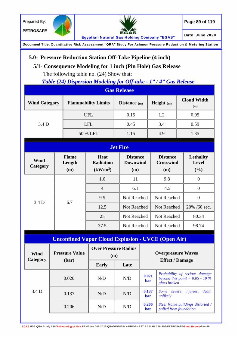
Page 89 of 119
Egyptian Natural Gas Holding Company “EGAS”
Prepared By: PETROSAFE
Date: June 2020
Document Title: Quantitative Risk Assessment “QRA” Study For Ashmon Pressure Reduction & Metering Station
EGAS.HSE.QRA.Study.018/Ashmon-Egypt.Gas.PRMS.No.006/2020/QRA/MG/MS/MY-DNV-PHAST.8.2/UAN.156,393-PETROSAFE-Final.Report-Rev.00
5.0- Pressure Reduction Station Off-Take Pipeline (4 inch) 5/1- Consequence Modeling for 1 inch (Pin Hole) Gas Release
The following table no. (24) Show that: Table (24) Dispersion Modeling for Off-take - 1” / 4” Gas Release
Gas Release
Wind Category Flammability Limits Distance (m) Height (m) Cloud Width (m)
3.4 D
UFL 0.15 1.2 0.95
LFL 0.45 3.4 0.59
50 % LFL 1.15 4.9 1.35
Jet Fire
Wind Category
Flame Length
(m)
Heat Radiation (kW/m2)
Distance Downwind
(m)
Distance Crosswind
(m)
Lethality Level (%)
3.4 D 6.7
1.6 11 9.8 0
4 6.1 4.5 0
9.5 Not Reached Not Reached 0
12.5 Not Reached Not Reached 20% /60 sec.
25 Not Reached Not Reached 80.34
37.5 Not Reached Not Reached 98.74
Unconfined Vapor Cloud Explosion - UVCE (Open Air)
Wind Category
Pressure Value (bar)
Over Pressure Radius (m) Overpressure Waves
Effect / Damage Early Late
3.4 D
0.020 N/D N/D 0.021 bar
Probability of serious damage beyond this point = 0.05 - 10 % glass broken
0.137 N/D N/D 0.137 bar
Some severe injuries, death unlikely
0.206 N/D N/D 0.206 bar
Steel frame buildings distorted / pulled from foundation
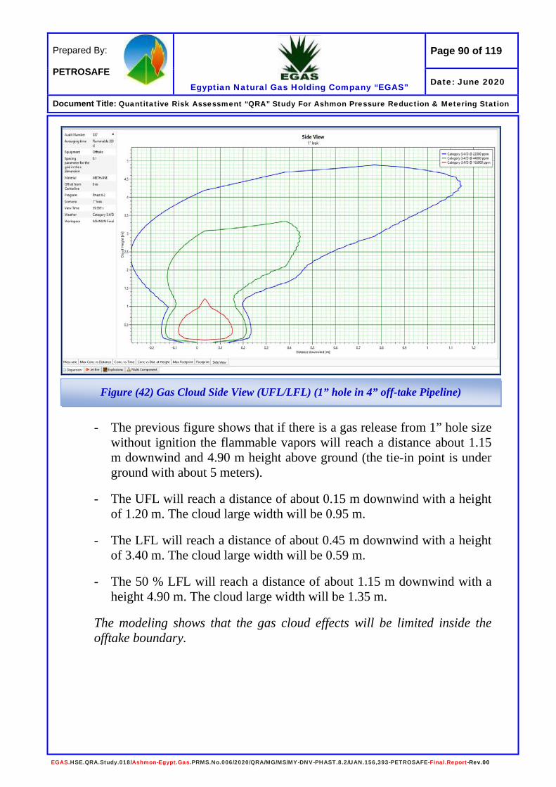
Page 90 of 119
Egyptian Natural Gas Holding Company “EGAS”
Prepared By: PETROSAFE
Date: June 2020
Document Title: Quantitative Risk Assessment “QRA” Study For Ashmon Pressure Reduction & Metering Station
EGAS.HSE.QRA.Study.018/Ashmon-Egypt.Gas.PRMS.No.006/2020/QRA/MG/MS/MY-DNV-PHAST.8.2/UAN.156,393-PETROSAFE-Final.Report-Rev.00
- The previous figure shows that if there is a gas release from 1” hole size without ignition the flammable vapors will reach a distance about 1.15 m downwind and 4.90 m height above ground (the tie-in point is under ground with about 5 meters).
- The UFL will reach a distance of about 0.15 m downwind with a height of 1.20 m. The cloud large width will be 0.95 m.
- The LFL will reach a distance of about 0.45 m downwind with a height of 3.40 m. The cloud large width will be 0.59 m.
- The 50 % LFL will reach a distance of about 1.15 m downwind with a height 4.90 m. The cloud large width will be 1.35 m.
The modeling shows that the gas cloud effects will be limited inside the offtake boundary.
Figure (42) Gas Cloud Side View (UFL/LFL) (1” hole in 4” off-take Pipeline)

Page 91 of 119
Egyptian Natural Gas Holding Company “EGAS”
Prepared By: PETROSAFE
Date: June 2020
Document Title: Quantitative Risk Assessment “QRA” Study For Ashmon Pressure Reduction & Metering Station
EGAS.HSE.QRA.Study.018/Ashmon-Egypt.Gas.PRMS.No.006/2020/QRA/MG/MS/MY-DNV-PHAST.8.2/UAN.156,393-PETROSAFE-Final.Report-Rev.00
- The previous figure shows that if there is a gas release from 1” hole size and ignited the expected flame length is about 6.70 meters height.
- The 1.6 kW/m2 heat radiation contours extend about 11 meters downwind and 9.80 meters crosswind.
- The 4 kW/m2 heat radiation contours extend about 6.10 meters downwind and 4.50 meters crosswind.
- The 9.5 kW/m2 heat radiation not determined. - The 12.5 kW/m2 heat radiation not determined. - The 25 kW/m2 heat radiation not determined. - The 37.5 kW/m2 heat radiation not determined. The modeling shows that the heat radiation value of 1.6 kW/m2 will be limited inside the offtake boundary, while the 4 kW/m2 will cover the offtake boundary and extends outside it with no effects. The values of 9.5, 12.5, 25 & 37.5 kW/m2 not determined by the software as they are very small values.
Figure (43) Heat Radiation Contours from Jet Fire (1” hole in 4” off-take Pipeline)
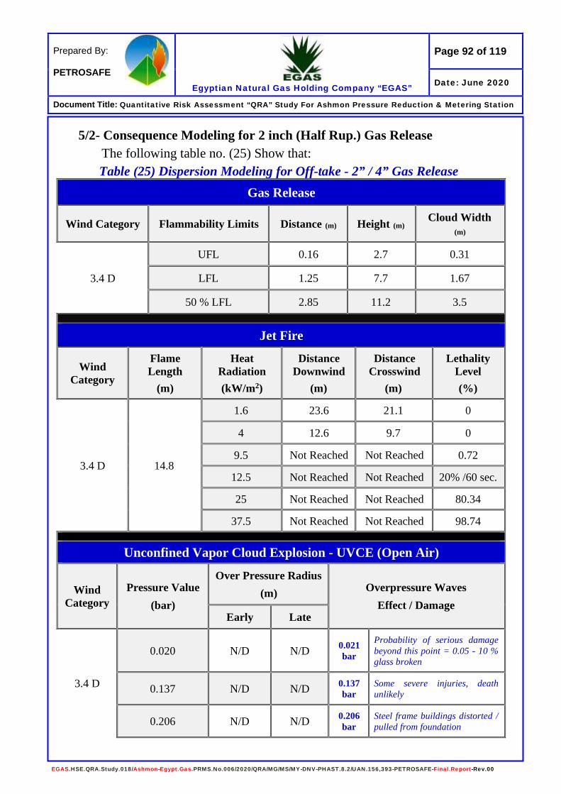
Page 92 of 119
Egyptian Natural Gas Holding Company “EGAS”
Prepared By: PETROSAFE
Date: June 2020
Document Title: Quantitative Risk Assessment “QRA” Study For Ashmon Pressure Reduction & Metering Station
EGAS.HSE.QRA.Study.018/Ashmon-Egypt.Gas.PRMS.No.006/2020/QRA/MG/MS/MY-DNV-PHAST.8.2/UAN.156,393-PETROSAFE-Final.Report-Rev.00
5/2- Consequence Modeling for 2 inch (Half Rup.) Gas Release The following table no. (25) Show that: Table (25) Dispersion Modeling for Off-take - 2” / 4” Gas Release
Gas Release
Wind Category Flammability Limits Distance (m) Height (m) Cloud Width (m)
3.4 D
UFL 0.16 2.7 0.31
LFL 1.25 7.7 1.67
50 % LFL 2.85 11.2 3.5
Jet Fire
Wind Category
Flame Length
(m)
Heat Radiation (kW/m2)
Distance Downwind
(m)
Distance Crosswind
(m)
Lethality Level (%)
3.4 D 14.8
1.6 23.6 21.1 0
4 12.6 9.7 0
9.5 Not Reached Not Reached 0.72
12.5 Not Reached Not Reached 20% /60 sec.
25 Not Reached Not Reached 80.34
37.5 Not Reached Not Reached 98.74
Unconfined Vapor Cloud Explosion - UVCE (Open Air)
Wind Category
Pressure Value (bar)
Over Pressure Radius (m) Overpressure Waves
Effect / Damage Early Late
3.4 D
0.020 N/D N/D 0.021 bar
Probability of serious damage beyond this point = 0.05 - 10 % glass broken
0.137 N/D N/D 0.137 bar
Some severe injuries, death unlikely
0.206 N/D N/D 0.206 bar
Steel frame buildings distorted / pulled from foundation

Page 93 of 119
Egyptian Natural Gas Holding Company “EGAS”
Prepared By: PETROSAFE
Date: June 2020
Document Title: Quantitative Risk Assessment “QRA” Study For Ashmon Pressure Reduction & Metering Station
EGAS.HSE.QRA.Study.018/Ashmon-Egypt.Gas.PRMS.No.006/2020/QRA/MG/MS/MY-DNV-PHAST.8.2/UAN.156,393-PETROSAFE-Final.Report-Rev.00
- The previous figure shows that if there is a gas release from 2” hole size without ignition the flammable vapors will reach a distance about 2.85 m downwind and 11.20 m height above ground (the tie-in point is under ground with about 5 meters).
- The UFL will reach a distance of about 0.16 m downwind with a height of 2.70 m. The cloud large width will be 0.31 m.
- The LFL will reach a distance of about 1.25 m downwind with a height of 7.70 m. The cloud large width will be 1.67 m.
- The 50 % LFL will reach a distance of about 2.85 m downwind with a height 11.20 m. The cloud large width will be 3.50 m.
The modeling shows that the gas cloud effects will be limited inside the Offtake boundary.
Figure (44) Gas Cloud Side View (UFL/LFL) (2” hole in 4” off-take Pipeline)

Page 94 of 119
Egyptian Natural Gas Holding Company “EGAS”
Prepared By: PETROSAFE
Date: June 2020
Document Title: Quantitative Risk Assessment “QRA” Study For Ashmon Pressure Reduction & Metering Station
EGAS.HSE.QRA.Study.018/Ashmon-Egypt.Gas.PRMS.No.006/2020/QRA/MG/MS/MY-DNV-PHAST.8.2/UAN.156,393-PETROSAFE-Final.Report-Rev.00
- The previous figure shows that if there is a gas release from 2” hole size and ignited the expected flame length is about 14.80 meters height.
- The 1.6 kW/m2 heat radiation contours extend about 23.60 meters downwind and 21.10 meters crosswind.
- The 4 kW/m2 heat radiation contours extend about 12.60 meters downwind and 9.70 meters crosswind.
- The 9.5 kW/m2 heat radiation not determined. - The 12.5 kW/m2 heat radiation not determined. - The 25 kW/m2 heat radiation not determined. - The 37.5 kW/m2 heat radiation not determined. The modeling shows that the heat radiation values of 1.6 & 4 kW/m2 will cover the offtake boundary and extend outside it with no effects. The values of 9.5, 12.5, 25 & 37.5 kW/m2 not determined by the software as they are very small values.
Figure (45) Heat Radiation Contours from Jet Fire (2” hole in 4” off-take Pipeline)

Page 95 of 119
Egyptian Natural Gas Holding Company “EGAS”
Prepared By: PETROSAFE
Date: June 2020
Document Title: Quantitative Risk Assessment “QRA” Study For Ashmon Pressure Reduction & Metering Station
EGAS.HSE.QRA.Study.018/Ashmon-Egypt.Gas.PRMS.No.006/2020/QRA/MG/MS/MY-DNV-PHAST.8.2/UAN.156,393-PETROSAFE-Final.Report-Rev.00
5/3- Consequence Modeling for 4 inch (Full Rup.) Gas Release The following table no. (26) Shows that:
Table (26) Dispersion Modeling for Off-take - 4” Gas Release Gas Release
Wind Category Flammability Limits Distance (m) Height (m) Cloud Width (m)
3.4 D
UFL 0.5 6.5 0.8
LFL 3.1 18 4.1
50 % LFL 7.4 26 8.9
Jet Fire
Wind Category
Flame Length
(m)
Heat Radiation (kW/m2)
Distance Downwind
(m)
Distance Crosswind
(m)
Lethality Level (%)
3.4 D 32.4
1.6 49.5 44.7 0
4 25.3 20.5 0
9.5 Not reached Not reached 0
12.5 Not reached Not reached 20% /60 sec.
25 Not reached Not reached 80.34
37.5 Not reached Not reached 98.74
Unconfined Vapor Cloud Explosion - UVCE (Open Air)
Wind Category
Pressure Value (bar)
Over Pressure Radius (m) Overpressure Waves
Effect / Damage
Early Late
3.4 D
0.020 N/D N/D 0.021 bar
Probability of serious damage beyond this point = 0.05 - 10 % glass broken
0.137 N/D N/D 0.137 bar
Some severe injuries, death unlikely
0.206 N/D N/D 0.206 bar
Steel frame buildings distorted / pulled from foundation
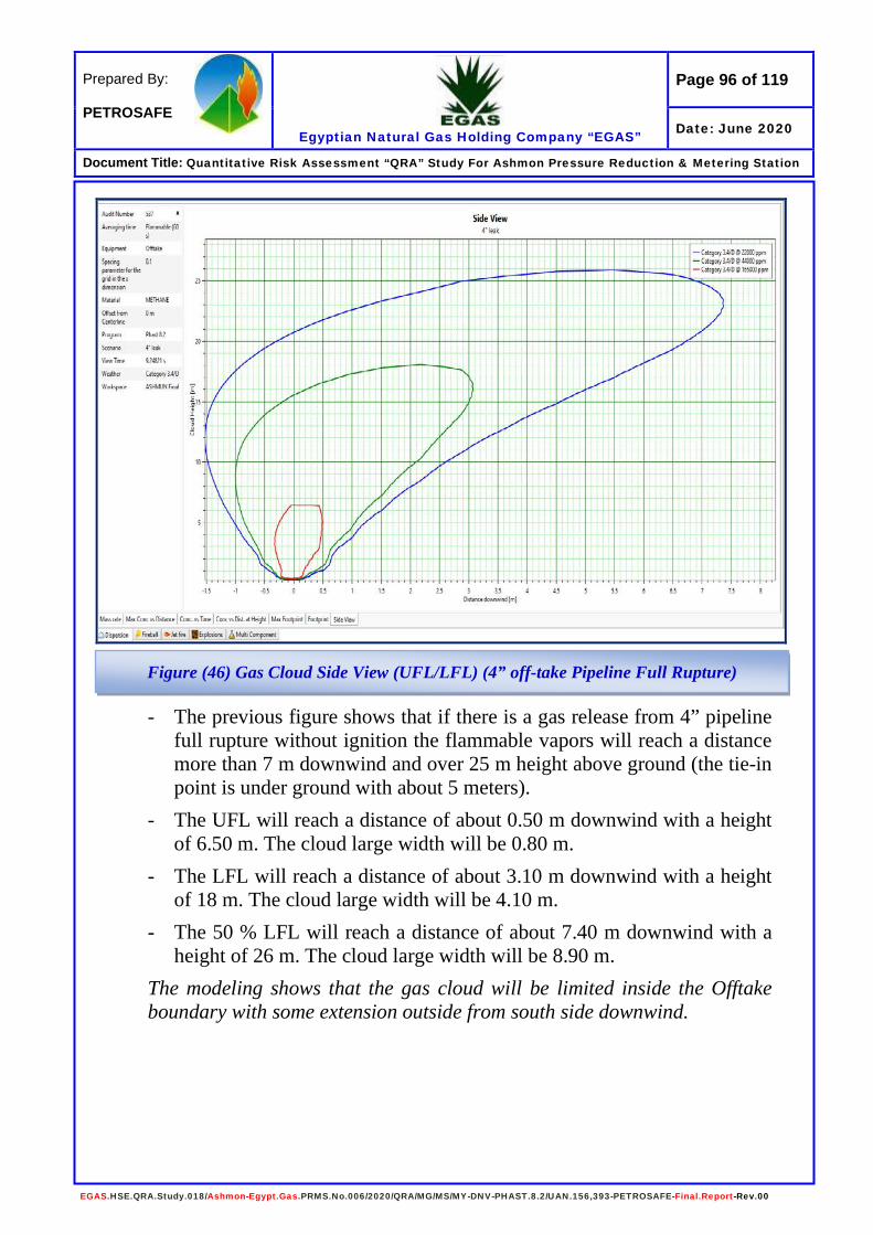
Page 96 of 119
Egyptian Natural Gas Holding Company “EGAS”
Prepared By: PETROSAFE
Date: June 2020
Document Title: Quantitative Risk Assessment “QRA” Study For Ashmon Pressure Reduction & Metering Station
EGAS.HSE.QRA.Study.018/Ashmon-Egypt.Gas.PRMS.No.006/2020/QRA/MG/MS/MY-DNV-PHAST.8.2/UAN.156,393-PETROSAFE-Final.Report-Rev.00
- The previous figure shows that if there is a gas release from 4” pipeline full rupture without ignition the flammable vapors will reach a distance more than 7 m downwind and over 25 m height above ground (the tie-in point is under ground with about 5 meters).
- The UFL will reach a distance of about 0.50 m downwind with a height of 6.50 m. The cloud large width will be 0.80 m.
- The LFL will reach a distance of about 3.10 m downwind with a height of 18 m. The cloud large width will be 4.10 m.
- The 50 % LFL will reach a distance of about 7.40 m downwind with a height of 26 m. The cloud large width will be 8.90 m.
The modeling shows that the gas cloud will be limited inside the Offtake boundary with some extension outside from south side downwind.
Figure (46) Gas Cloud Side View (UFL/LFL) (4” off-take Pipeline Full Rupture)

Page 97 of 119
Egyptian Natural Gas Holding Company “EGAS”
Prepared By: PETROSAFE
Date: June 2020
Document Title: Quantitative Risk Assessment “QRA” Study For Ashmon Pressure Reduction & Metering Station
EGAS.HSE.QRA.Study.018/Ashmon-Egypt.Gas.PRMS.No.006/2020/QRA/MG/MS/MY-DNV-PHAST.8.2/UAN.156,393-PETROSAFE-Final.Report-Rev.00
- The previous figure shows that if there is a gas release from 4” pipeline full rupture and ignited the expected flame length is about 32.40 meters height.
- The 1.6 kW/m2 heat radiation contours extend about 49.50 meters downwind and 44.70 meters crosswind.
- The 4 kW/m2 heat radiation contours extend about 25.30 meters downwind and 20.50 meters crosswind.
- The 9.5 kW/m2 heat radiation not determined. - The 12.5 kW/m2 heat radiation not determined. - The 25 kW/m2 heat radiation not determined. - The 37.5 kW/m2 heat radiation not determined. The modeling shows that the heat radiation values of 1.6 & 4 kW/m2 will cover the offtake boundary and extend outside it with no effects. The values of 9.5, 12.5, 25 & 37.5 kW/m2 not determined by the software as they are very small values.
Figure (47) Heat Radiation Contours from Jet Fire (4” off-take Pipeline Full Rupture)
Page 98 of 119
Egyptian Natural Gas Holding Company “EGAS”
Prepared By: PETROSAFE
Date: June 2020
Document Title: Quantitative Risk Assessment “QRA” Study For Ashmon Pressure Reduction & Metering Station
EGAS.HSE.QRA.Study.018/Ashmon-Egypt.Gas.PRMS.No.006/2020/QRA/MG/MS/MY-DNV-PHAST.8.2/UAN.156,393-PETROSAFE-Final.Report-Rev.00
Individual Risk Evaluation • Risk Calculation
All identified hazards should be subject to an evaluation for risk potential. This means analyzing the hazard for its probability to actually progress to loss event, as well as likely consequences of this event.
There are four steps to calculate risk, which determined as follows:
1- Identify failure frequency (International Data Base)
2- Calculating the frequency against control measures at site by using Event Tree Analysis “ETA”.
3- Identify scenarios probability.
4- Calculated risk to people regarding to the vulnerability of life loses.
Basically, risk will be calculated as presented in the following equation:
Risk to people (Individual Risk – IR) =
Total Risk (Σ Frequency of fire/explosion) x Occupancy x Vulnerability
Where:
Total risk Is the sum of contributions from all hazards exposed to (fire / explosion).
Occupancy Is the proportion of time exposed to work hazards. (Expected that x man the most exposed person to fire/explosion hazards on site. He works 8 hours shift/day)
Vulnerability Is the probability that exposure to the hazard will result in fatality.
As shown in tables (5 & 6) – (Page: 33 & 34) the vulnerability of people to heat radiation starting from 12.5 kW/m2 will lead to fatality accident for 60 sec. Exposure and for explosion over pressure starting from 0.137 bar.

Page 99 of 119
Egyptian Natural Gas Holding Company “EGAS”
Prepared By: PETROSAFE
Date: June 2020
Document Title: Quantitative Risk Assessment “QRA” Study For Ashmon Pressure Reduction & Metering Station
EGAS.HSE.QRA.Study.018/Ashmon-Egypt.Gas.PRMS.No.006/2020/QRA/MG/MS/MY-DNV-PHAST.8.2/UAN.156,393-PETROSAFE-Final.Report-Rev.00
The modeling of the different scenarios shows that the heat radiation and explosion overpressure waves would be a result from release scenarios for all sizes of crack and according to the space size for the PRMS, all of the sequence will be determined for three values release (small, medium and large).
Calculating frequencies needs a very comprehensive calculation which needs a lot of data collecting related to failure of equipment’s and accident reporting with detailed investigation to know the failure frequency rates in order to calculate risks from scenarios.
In this study, it is decided to use an International Data Bank for major hazardous incident data.
The following table (27) shows the frequency for each failure that can be raised in pressure reduction station operations:

Page 100 of 119
Egyptian Natural Gas Holding Company “EGAS”
Prepared By: PETROSAFE
Date: June 2020
Document Title: Quantitative Risk Assessment “QRA” Study For Ashmon Pressure Reduction & Metering Station
EGAS.HSE.QRA.Study.018/Ashmon-Egypt.Gas.PRMS.No.006/2020/QRA/MG/MS/MY-DNV-PHAST.8.2/UAN.156,393-PETROSAFE-Final.Report-Rev.00
Table (27) Failure Frequency for Each Scenario Scenario Release Size
Gas Release from 1”/4”- 6” Pipeline / 3” Gas Heater
Small
Failure Cause Failure Rate Internal Corrosion 1.19E-05
External Corrosion 3.55E-06
Maintenance Error 2.28E-05
Corrosive Liquid or Gas 4.84E-04
Total 5.22E-04 Gas Release from 2”/4”&3”/6” Pipeline
Medium
Failure Cause Failure Rate
Internal Corrosion 2.71E-05
External Corrosion 8.24E-06
Erosion 4.85E-04
Total 5.20E-04 Gas Release from 4” / 6” Pipeline Full Rupture
Large
Failure Cause Failure Rate
Internal Corrosion 5.53E-06
External Corrosion 1.61E-06
Weld Crack 4.34E-06
Earthquake 1.33E-07
Total 1.16E-05 Spotleak (Odorant Tank)
Medium
As a package Failure Rate Reference: Taylor Associates ApS - 2006
(Hazardous Materials Release and Accident Frequencies for Process Plant - Volume II / Process Unit Release Frequencies - Version 1 Issue 7)
1.25E-05
Page 101 of 119
Egyptian Natural Gas Holding Company “EGAS”
Prepared By: PETROSAFE
Date: June 2020
Document Title: Quantitative Risk Assessment “QRA” Study For Ashmon Pressure Reduction & Metering Station
EGAS.HSE.QRA.Study.018/Ashmon-Egypt.Gas.PRMS.No.006/2020/QRA/MG/MS/MY-DNV-PHAST.8.2/UAN.156,393-PETROSAFE-Final.Report-Rev.00
• Event Tree Analysis An event tree is a graphical way of showing the possible outcomes of a hazardous event, such as a failure of equipment or human error. An ETA involves determining the responses of systems and operators to the hazardous event in order to determine all possible alternative outcomes. The result of the ETA is a series of scenarios arising from different sets of failures or errors. These scenarios describe the possible accident outcomes in terms of the sequence of events (successes or failures of safety functions) that follow the initial hazardous event. Event trees shall be used to identify the various escalation paths that can occur in the process. After these escalation paths are identified, the specific combinations of failures that can lead to defined outcomes can then be determined. This allows identification of additional barriers to reduce the likelihood of such escalation. The results of an ETA are the event tree models and the safety system successes or failures that lead to each defined outcome. Accident sequences represents in an event tree represent logical and combinations of events; thus, these sequences can be put into the form of a fault tree model for further qualitative analysis. These results may be used to identify design and procedural weaknesses, and normally to provide recommendations for reducing the likelihood and/or consequences of the analyzed potential accidents. Using ETA requires knowledge of potential initiating events (that is, equipment failures or system upsets that can potentially cause an accident), and knowledge of safety system functions or emergency procedures that potentially mitigate the effects of each initiating event. The equipment failures, system upsets and safety system functions shall be extracted from the likelihood data presented before.

Page 102 of 119
Egyptian Natural Gas Holding Company “EGAS”
Prepared By: PETROSAFE
Date: June 2020
Document Title: Quantitative Risk Assessment “QRA” Study For Ashmon Pressure Reduction & Metering Station
EGAS.HSE.QRA.Study.018/Ashmon-Egypt.Gas.PRMS.No.006/2020/QRA/MG/MS/MY-DNV-PHAST.8.2/UAN.156,393-PETROSAFE-Final.Report-Rev.00
In the case of hydrocarbon release, the event tree first branch is typically representing "Early Ignition". These events are represented in the risk analysis as jet fire events. This is because sufficient time is unlikely to elapse before ignition for a gas/air mixture to accumulate and cause either a flash fire or a gas hazard. Subsequent branches for these events represent gas detection, fire detection, inventory isolation (or ESD) or deluge activation. Delayed ignitions are typically represented by the fifth branch event. This is because, in the time taken for an ignition to occur, sufficient time is more likely to elapse for gas detection and inventory isolation. The scenario development shall be performed for the following cases:
- Without any control measures - With control measures
The event tree analysis outcomes can be classified into three main categories as follows:
“Limited Consequence” Indicates that the release has been detected and the inventory source has been isolated automatically.
“Controlled Consequence” Indicates that the release has been detected but the source has not been isolated automatically. [Needs human intervention].
“Escalated Consequence” Indicates that the release has not been detected and consequently the source has not been isolated.
The event trees analysis for each scenario are presented in the below pages:

Page 103 of 119
Egyptian Natural Gas Holding Company “EGAS”
Prepared By: PETROSAFE
Date: June 2020
Document Title: Quantitative Risk Assessment “QRA” Study For Ashmon Pressure Reduction & Metering Station
EGAS.HSE.QRA.Study.018/Ashmon-Egypt.Gas.PRMS.No.006/2020/QRA/MG/MS/MY-DNV-PHAST.8.2/UAN.156,393-PETROSAFE-Final.Report-Rev.00
ESD
System (3)
5.22E-04 0.02 0.6 0.978 0.97 0.02
0.970.6
0.03
0.020.4
5.22E-04 0.978
0.0220.98
0.02
0.98
Table (28) Inlet 4” / Outlet 6” / Off-Take 4”/ Waterbath 3” Pipeline Scenarios (Pin Hole Crack – 1” Release) – Event Tree Analysis
Release of Flammable Materials (1)
Immediate Ignition (2) Fire Detection (3) Fire Protec. (3) Delayed Ignition (2)
Outcomes Frequency
Controlled Jet fire 1.01E-05
Not controlled jet fire 3.13E-07
Escalated jet fire 4.18E-06
Limited release -------------
Large release 1.13E-05
Escalated jet fire 1.02E-05
Escalated release 5.01E-04(1) Refer to QRA Study Page 94. (Taylor Associates ApS - 2006)
(2) Ref. Handbook Failure Frequencies 2009.TOTAL 1.47E-05
(3) Ref. OGP – Report No. 434 – A1 / 2010.
Yes
No
Yes
Yes
Yes
Yes
No
No
No
No

Page 104 of 119
Egyptian Natural Gas Holding Company “EGAS”
Prepared By: PETROSAFE
Date: June 2020
Document Title: Quantitative Risk Assessment “QRA” Study For Ashmon Pressure Reduction & Metering Station
EGAS.HSE.QRA.Study.018/Ashmon-Egypt.Gas.PRMS.No.006/2020/QRA/MG/MS/MY-DNV-PHAST.8.2/UAN.156,393-PETROSAFE-Final.Report-Rev.00
ESD
System (3)
5.20E-04 0.02 0.6 0.978 0.97 0.02
0.970.6
0.03
0.020.4
5.20E-04 0.978
0.0220.98
0.02
0.98
Table (29) Inlet 4” / Outlet 6” / Off-Take 4” Pipeline Scenarios (Half Rupture Release) – Event Tree Analysis
Release of Flammable Materials (1)
Immediate Ignition (2) Fire Detection (3) Fire Protec. (3) Delayed Ignition (2)
Outcomes Frequency
Controlled Jet fire 1.01E-05
Not controlled jet fire 3.12E-07
Escalated jet fire 4.16E-06
Limited release -------------
Large release 1.12E-05
Escalated jet fire 1.02E-05
Escalated release 4.99E-04(1) Refer to QRA Study Page 94. (Taylor Associates ApS - 2006)
(2) Ref. Handbook Failure Frequencies 2009.TOTAL 1.47E-05
(3) Ref. OGP – Report No. 434 – A1 / 2010.
Yes
No
Yes
Yes
Yes
Yes
No
No
No
No
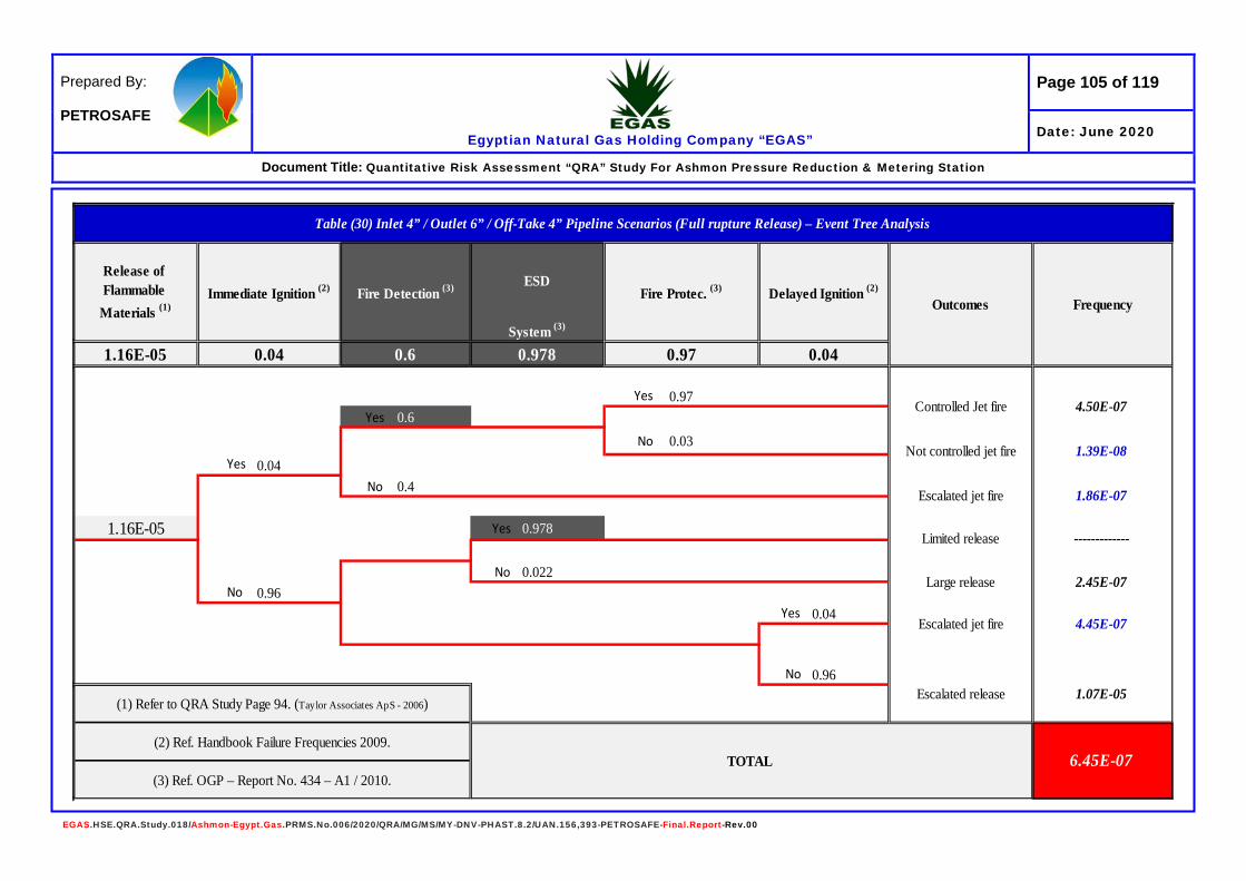
Page 105 of 119
Egyptian Natural Gas Holding Company “EGAS”
Prepared By: PETROSAFE
Date: June 2020
Document Title: Quantitative Risk Assessment “QRA” Study For Ashmon Pressure Reduction & Metering Station
EGAS.HSE.QRA.Study.018/Ashmon-Egypt.Gas.PRMS.No.006/2020/QRA/MG/MS/MY-DNV-PHAST.8.2/UAN.156,393-PETROSAFE-Final.Report-Rev.00
ESD
System (3)
1.16E-05 0.04 0.6 0.978 0.97 0.04
0.970.6
0.03
0.040.4
1.16E-05 0.978
0.0220.96
0.04
0.96
Table (30) Inlet 4” / Outlet 6” / Off-Take 4” Pipeline Scenarios (Full rupture Release) – Event Tree Analysis
Release of Flammable Materials (1)
Immediate Ignition (2) Fire Detection (3) Fire Protec. (3) Delayed Ignition (2)
Outcomes Frequency
Controlled Jet fire 4.50E-07
Not controlled jet fire 1.39E-08
Escalated jet fire 1.86E-07
Limited release -------------
Large release 2.45E-07
Escalated jet fire 4.45E-07
Escalated release 1.07E-05(1) Refer to QRA Study Page 94. (Taylor Associates ApS - 2006)
(2) Ref. Handbook Failure Frequencies 2009.TOTAL 6.45E-07
(3) Ref. OGP – Report No. 434 – A1 / 2010.
Yes
No
Yes
Yes
Yes
Yes
No
No
No
No

Page 106 of 119
Egyptian Natural Gas Holding Company “EGAS”
Prepared By: PETROSAFE
Date: June 2020
Document Title: Quantitative Risk Assessment “QRA” Study For Ashmon Pressure Reduction & Metering Station
EGAS.HSE.QRA.Study.018/Ashmon-Egypt.Gas.PRMS.No.006/2020/QRA/MG/MS/MY-DNV-PHAST.8.2/UAN.156,393-PETROSAFE-Final.Report-Rev.00
ESD
System (3)
1.25E-05 0.065 0.6 0.978 0.97 0.07
0.970.6
0.03
0.0650.4
1.25E-05 0.978
0.0220.935
0.07
0.93
Table (31) Odorant Tank Release – Event Tree Analysis
Release of Flammable Materials (1)
Immediate Ignition (2) Fire Detection (3) Fire Protec. (3) Delayed Ignition (2)
Outcomes Frequency
Controlled Jet fire 7.88E-07
Large fire 2.44E-08
Escalated jet fire 3.25E-07
Limited leak -------------
Large leak 2.57E-07
Escalated jet fire 8.18E-07
Escalated leak 1.09E-05(1) Refer to QRA Study Page 94. (Taylor Associates ApS - 2006)
(2) Ref. Handbook Failure Frequencies 2009.TOTAL 1.23E-05
(3) Ref. OGP – Report No. 434 – A1 / 2010.
Yes
No
Yes
Yes
Yes
Yes
No
No
No
No

Page 107 of 119
Egyptian Natural Gas Holding Company “EGAS”
Prepared By: PETROSAFE
Date: June 2020
Document Title: Quantitative Risk Assessment “QRA” Study For Ashmon Pressure Reduction & Metering Station
EGAS.HSE.QRA.Study.018/Ashmon-Egypt.Gas.PRMS.No.006/2020/QRA/MG/MS/MY-DNV-PHAST.8.2/UAN.156,393-PETROSAFE-Final.Report-Rev.00
The following table (32) shows the total frequency for each scenario from ETA - Tables (28 to 31):
Table (32) Total Frequencies for Each Scenario
Source of Release Total Frequency (ETA) 1” / 4” Inlet Pipeline Pin Hole
1.47E-05 1” / 4” Off-Take Pipeline Pin Hole 1” / 6” Outlet Pipeline Pin Hole 1” / 3” Gas Heater Pin Hole
2” / 4” Inlet Pipeline Half Rupture 1.47E-05 2” / 4” Off-Take Pipeline Half Rupture
3” / 6” Outlet Pipeline Half Rupture
4” Inlet Pipeline Full Rupture 6.45E-07 4” Off-Take Pipeline Full Rupture
6” Outlet Pipeline Full Rupture
Odorant Tank 1” hole Leak 1.23E-05 The following table (33) summarize the risk events on workers / public, and as there is no direct effects on public from any of the scenarios it will be assumed that one person (as public) works as farmer for 1 hour / day light, And one operator (as worker) for operation / maintenance inside the PRS boundary for 2 hours / day light.
Table No. (33) Summarize the Risk on Workers / Public (Occupancy) Inlet 4” Pipeline Release Scenarios
Event Jet / Pool Fire (12.5 kW/m2) Explosion Overpressure (0.137 bar) Exposure Workers Public Workers Public
Pin Hole 1” None None None None Half Rupture 2” None None None 1 for 1 h (0.04) Full Rupture 4” None 1 for 1 h (0.04) None 1 for 1 h (0.04)
Outlet 6” Pipeline Release Scenarios Pin Hole 1” None None None None
Half Rupture 3” None 1 for 1 h (0.04) None 1 for 1 h (0.04) Full Rupture 6” 1 for 2 h (0.08) 1 for 1 h (0.04) None 1 for 1 h (0.04)
Odorant Tank Release Scenario Small Leak 1” 1 for 2 h (0.08) None None 1 for 1 h (0.04)
Gas heater (water bath heating system) Pin Hole 1” 1 for 2 h (0.08) None 1 for 2 h (0.08) None
Off-Take 4” Pipeline Release Scenarios Pin Hole 1” None None None None
Half Rupture 2” None None None None Full Rupture 4” None None None None
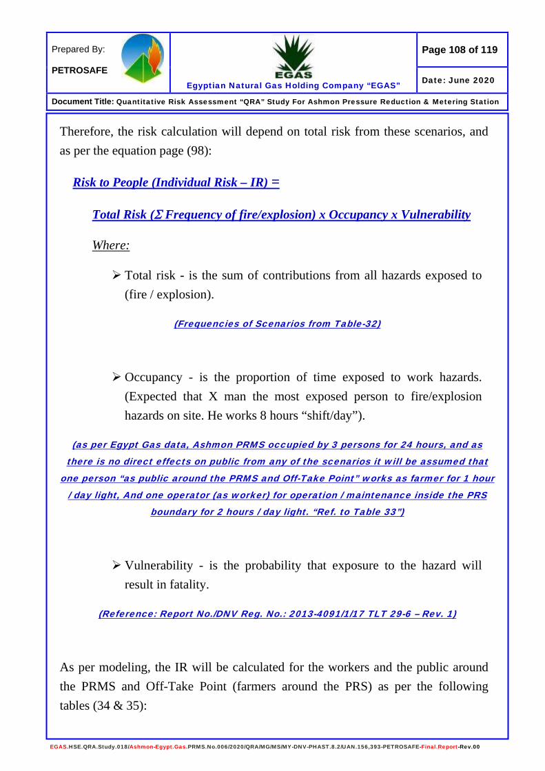
Page 108 of 119
Egyptian Natural Gas Holding Company “EGAS”
Prepared By: PETROSAFE
Date: June 2020
Document Title: Quantitative Risk Assessment “QRA” Study For Ashmon Pressure Reduction & Metering Station
EGAS.HSE.QRA.Study.018/Ashmon-Egypt.Gas.PRMS.No.006/2020/QRA/MG/MS/MY-DNV-PHAST.8.2/UAN.156,393-PETROSAFE-Final.Report-Rev.00
Therefore, the risk calculation will depend on total risk from these scenarios, and as per the equation page (98):
Risk to People (Individual Risk – IR) =
Total Risk (Σ Frequency of fire/explosion) x Occupancy x Vulnerability
Where:
Total risk - is the sum of contributions from all hazards exposed to (fire / explosion).
(Frequencies of Scenarios from Table-32)
Occupancy - is the proportion of time exposed to work hazards. (Expected that X man the most exposed person to fire/explosion hazards on site. He works 8 hours “shift/day”).
(as per Egypt Gas data, Ashmon PRMS occupied by 3 persons for 24 hours, and as
there is no direct effects on public from any of the scenarios it will be assumed that
one person “as public around the PRMS and Off-Take Point” works as farmer for 1 hour
/ day light, And one operator (as worker) for operation / maintenance inside the PRS boundary for 2 hours / day light. “Ref. to Table 33”)
Vulnerability - is the probability that exposure to the hazard will result in fatality.
(Reference: Report No./DNV Reg. No.: 2013-4091/1/17 TLT 29-6 – Rev. 1)
As per modeling, the IR will be calculated for the workers and the public around the PRMS and Off-Take Point (farmers around the PRS) as per the following tables (34 & 35):

Page 109 of 119
Egyptian Natural Gas Holding Company “EGAS”
Prepared By: PETROSAFE
Date: June 2020
Document Title: Quantitative Risk Assessment “QRA” Study For Ashmon Pressure Reduction & Metering Station
EGAS.HSE.QRA.Study.018/Ashmon-Egypt.Gas.PRMS.No.006/2020/QRA/MG/MS/MY-DNV-PHAST.8.2/UAN.156,393-PETROSAFE-Final.Report-Rev.00
Table (34) Individual Risk (IR) Calculation for the Workers Near to the PRMS
Source of Event
Frequency 1
Heat Radiation
(kW/m2) &
Overpressure (Bar)
Vulnerability 2
Time Exposed
3
IR =
1 x 2 x 3
Gas Release from 1”/ 3” Gas Heater
1.47E-05 Jet Fire 12.5
0.7 (Outdoor) 0.08 1 Pers.
8.23E-07
Gas Release from 1”/ 3” Gas Heater
1.47E-05 Explosion 0.137
0.3 (Outdoor) 0.08 1 Pers. 3.53E-07
Gas Release from 6” outlet pipeline
6.45E-07 Jet Fire 12.5
0.7 (Outdoor) 0.08 1 Pers. 3.61E-08
Odorant tank 1” leak 1.23E-05 Jet Fire
12.5 0.7
(Outdoor) 0.08 1 Pers. 6.89E-07
TOTAL Risk for the Workers 1.90E-06
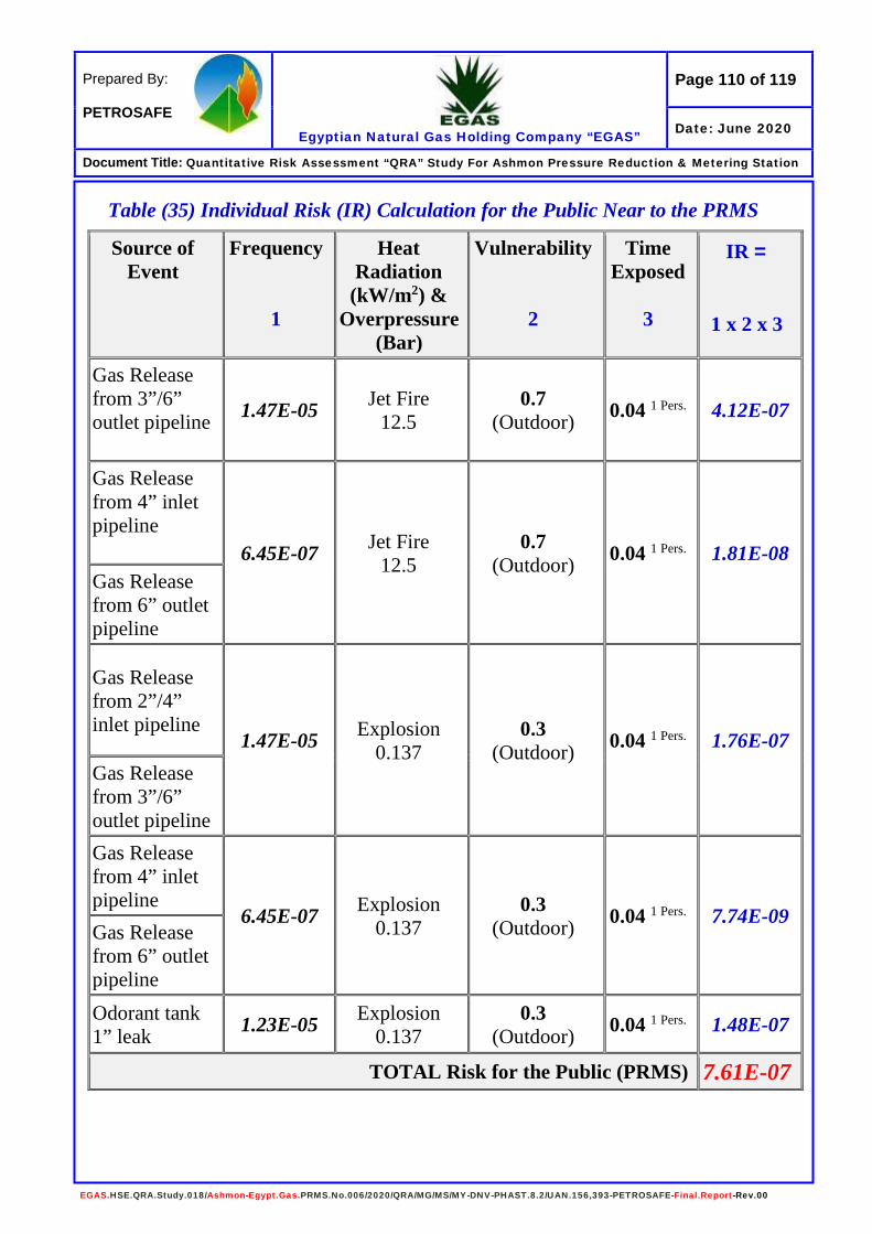
Page 110 of 119
Egyptian Natural Gas Holding Company “EGAS”
Prepared By: PETROSAFE
Date: June 2020
Document Title: Quantitative Risk Assessment “QRA” Study For Ashmon Pressure Reduction & Metering Station
EGAS.HSE.QRA.Study.018/Ashmon-Egypt.Gas.PRMS.No.006/2020/QRA/MG/MS/MY-DNV-PHAST.8.2/UAN.156,393-PETROSAFE-Final.Report-Rev.00
Table (35) Individual Risk (IR) Calculation for the Public Near to the PRMS
Source of Event
Frequency 1
Heat Radiation
(kW/m2) &
Overpressure (Bar)
Vulnerability 2
Time Exposed
3
IR =
1 x 2 x 3
Gas Release from 3”/6” outlet pipeline
1.47E-05 Jet Fire 12.5
0.7 (Outdoor) 0.04 1 Pers.
4.12E-07
Gas Release from 4” inlet pipeline 6.45E-07 Jet Fire
12.5 0.7
(Outdoor) 0.04 1 Pers. 1.81E-08 Gas Release from 6” outlet pipeline
Gas Release from 2”/4” inlet pipeline
1.47E-05 Explosion 0.137
0.3 (Outdoor) 0.04 1 Pers. 1.76E-07
Gas Release from 3”/6” outlet pipeline Gas Release from 4” inlet pipeline
6.45E-07 Explosion 0.137
0.3 (Outdoor) 0.04 1 Pers. 7.74E-09
Gas Release from 6” outlet pipeline Odorant tank 1” leak 1.23E-05 Explosion
0.137 0.3
(Outdoor) 0.04 1 Pers. 1.48E-07
TOTAL Risk for the Public (PRMS) 7.61E-07

Page 111 of 119
Egyptian Natural Gas Holding Company “EGAS”
Prepared By: PETROSAFE
Date: June 2020
Document Title: Quantitative Risk Assessment “QRA” Study For Ashmon Pressure Reduction & Metering Station
EGAS.HSE.QRA.Study.018/Ashmon-Egypt.Gas.PRMS.No.006/2020/QRA/MG/MS/MY-DNV-PHAST.8.2/UAN.156,393-PETROSAFE-Final.Report-Rev.00
Figure (49) Evaluation of Individual Risk The level of Individual Risk to the exposed workers at Ashmon PRMS, based on the risk tolerability criterion used is Acceptable. The level of Individual Risk to the exposed Public at Ashmon PRMS area, based on the risk tolerability criterion used is Acceptable.
1.90E-06
Maximum Tolerable Limit
Minimum Tolerable Limit
Workers
1 in 1000 per year
ALARP or Tolerability Region
Minimum Tolerable Limit
Maximum Tolerable Limit
1 in 100,000 per year
1 in 10,000 per year
1 in 1 million per year
Public
Risk must be demonstrated to have been reduced to a level, which is
practicable with a view to cost/benefit
ACCEPTABLE REGION
ACCEPTABLE REGION
ALARP or Tolerability Region
INDIVIDUAL RISK TO THE PUBLIC All those not directly involved with
company activities
INDIVIDUAL RISK TO WORKERS Including contractor employees
UNACCEPTABLE REGION
ALARP Benchmark existing installations 1 in 5,000 per year
ALARP Benchmark new installations 1 in 50,000 per year
1.0E-03/year
1.0E-05/year
1.0E-04/year
1.0E-06/year
Workers
Public
7.61E-07

Page 112 of 119
Egyptian Natural Gas Holding Company “EGAS”
Prepared By: PETROSAFE
Date: June 2020
Document Title: Quantitative Risk Assessment “QRA” Study For Ashmon Pressure Reduction & Metering Station
EGAS.HSE.QRA.Study.018/Ashmon-Egypt.Gas.PRMS.No.006/2020/QRA/MG/MS/MY-DNV-PHAST.8.2/UAN.156,393-PETROSAFE-Final.Report-Rev.00
Summary of Modeling Results and Conclusion As per results from modeling the consequences of each scenario, the following table summarize the study, and as follows:
Event Scenario Effects Pin hole (1”) gas release 4” inlet pipeline
Gas cloud UFL LFL 50 % LFL
The modeling shows that the gas cloud effects will be limited inside the PRMS boundary.
Heat radiation / Jet fire 9.5 kW/m2
12.5 kW/m2
The modeling shows that the heat radiation values will extend down and crosswind fence of the PRS boundary from the East side.
Early explosion 0.020 bar 0.137 bar 0.206 bar
N/D
Late explosion 0.020 bar 0.137 bar 0.206 bar
N/D
Half Rupture (2”) gas release 4” inlet pipeline Gas cloud
UFL LFL 50 % LFL
The modeling shows that the gas cloud (50 % LFL) will extend to reach the southern fence and extend about outside. The UFL & LFL will be limited inside the PRS boundary.
Heat radiation / Jet fire 9.5 kW/m2
12.5 kW/m2
The modeling shows that the values of 9.5 & 12.5 kW/m2 will extend outside the PRS southern fence downwind with no effects.
Early explosion 0.020 bar 0.137 bar 0.206 bar
N/D

Page 113 of 119
Egyptian Natural Gas Holding Company “EGAS”
Prepared By: PETROSAFE
Date: June 2020
Document Title: Quantitative Risk Assessment “QRA” Study For Ashmon Pressure Reduction & Metering Station
EGAS.HSE.QRA.Study.018/Ashmon-Egypt.Gas.PRMS.No.006/2020/QRA/MG/MS/MY-DNV-PHAST.8.2/UAN.156,393-PETROSAFE-Final.Report-Rev.00
Event Scenario Effects Late explosion
0.020 bar 0.137 bar 0.206 bar
The modeling shows that the value of 0.020, 0.137 & 0.206 bar will extend outside the PRMS south fence with no effects down or crosswind.
Full Rupture gas release 4” inlet pipeline Gas cloud
UFL LFL 50 % LFL
The modeling shows that the gas cloud effects (LFL & 50 % LFL) will extend over south boundary with no effects outside downwind.
Heat radiation / Jet fire 9.5 kW/m2
12.5 kW/m2
The modeling shows that the heat radiation values 9.5 & 12.5 kW/m2 will extend outside the south fence with no effects downwind.
Early explosion 0.020 bar 0.137 bar 0.206 bar
N/D
Late explosion 0.020 bar 0.137 bar 0.206 bar
The modeling shows that the value of 0.020 bar will cover the PRS and extend outside the PRS boundary with no effects outside and covering parts of the control room & the generator. The modeling shows that the value of 0.137 & 0.206 bar will extend outside the PRMS south fence with no effects down or crosswind.
Heat radiation / Fireball 9.5 kW/m2
12.5 kW/m2
N/D
Pin hole (1”) gas release 6” outlet pipeline Gas cloud
UFL LFL 50 % LFL
The modeling shows that the gas cloud will be limited inside the PRS boundary.
Heat radiation / Jet fire 9.5 kW/m2
12.5 kW/m2
The modeling shows that the heat radiation value 1.6, 4 & 9.5 kW/m2 effects will be limited inside the PRS boundary with no effects. The values of 12.5, 25 & 37.5 kW/m2 not determined by the software due to small leakage.

Page 114 of 119
Egyptian Natural Gas Holding Company “EGAS”
Prepared By: PETROSAFE
Date: June 2020
Document Title: Quantitative Risk Assessment “QRA” Study For Ashmon Pressure Reduction & Metering Station
EGAS.HSE.QRA.Study.018/Ashmon-Egypt.Gas.PRMS.No.006/2020/QRA/MG/MS/MY-DNV-PHAST.8.2/UAN.156,393-PETROSAFE-Final.Report-Rev.00
Event Scenario Effects Early explosion
0.020 bar 0.137 bar 0.206 bar
N/D
Late explosion 0.020 bar 0.137 bar 0.206 bar
N/D
Half Rupture (3”) gas release 6” outlet pipeline Gas cloud
UFL LFL 50 % LFL
The modeling shows that the gas cloud (UFL & LFL) will be limited inside the PRS boundary. While the 50% LFL will extend outside the PRS fence from the south side with no effects downwind.
Heat radiation / Jet fire 9.5 kW/m2
12.5 kW/m2
The modeling shows that the heat radiation values of 9.5, 12.5, 25 & 37.5 kW/m2 will extend outside the PRS boundary south side with no effects downwind.
Early explosion 0.020 bar 0.137 bar 0.206 bar
N/D
Late explosion 0.020 bar 0.137 bar 0.206 bar
The modeling shows that the value of 0.020 bar will cover the PRS and extend outside the PRS boundary with no effects outside and covering parts of the control room & the generator. The values of 0.137 & 0.206 bar will be extended outside the PRS boundary with no effect down or crosswind.
Full Rupture gas release 6” outlet pipeline Gas cloud
UFL LFL 50 % LFL
The modeling shows that the gas cloud effects will be limited inside the PRS boundary.
Heat radiation / Jet fire 9.5 kW/m2
12.5 kW/m2
The modeling shows that the heat radiation values 9.5, 12.5, 25 & 37.5 kW/m2 will extend outside the south fence with no effects down and crosswind.
Early explosion 0.020 bar 0.137 bar 0.206 bar
N/D
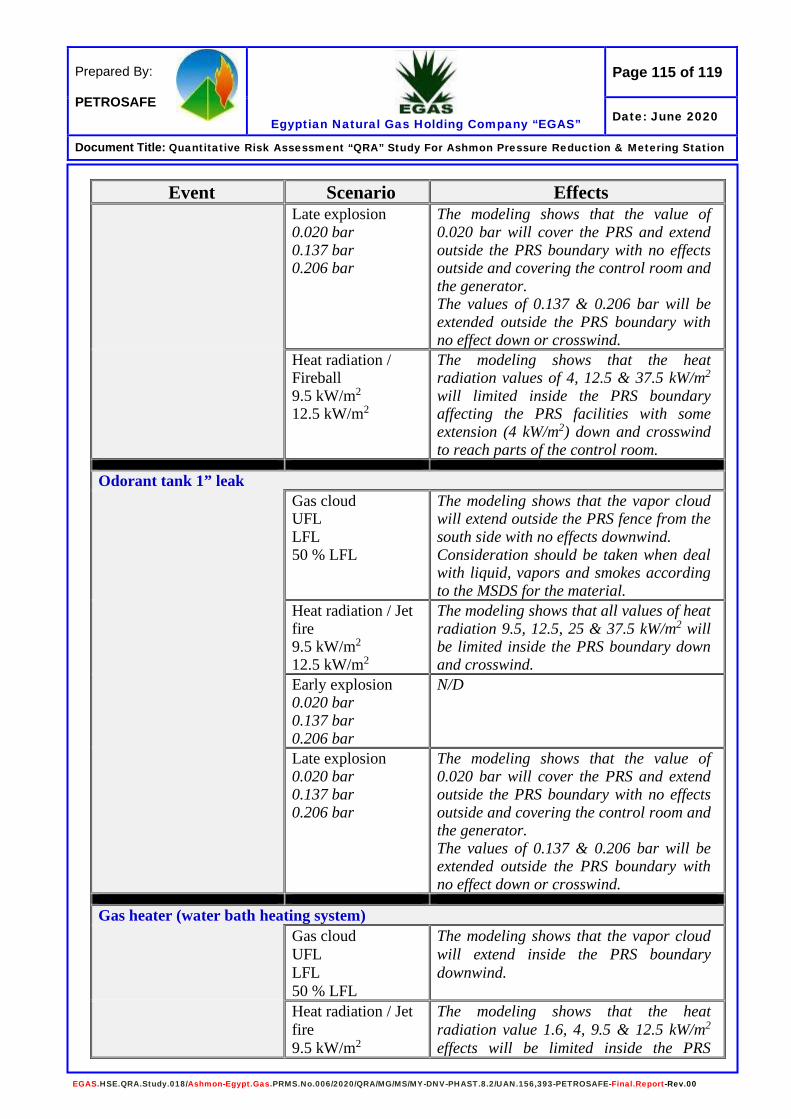
Page 115 of 119
Egyptian Natural Gas Holding Company “EGAS”
Prepared By: PETROSAFE
Date: June 2020
Document Title: Quantitative Risk Assessment “QRA” Study For Ashmon Pressure Reduction & Metering Station
EGAS.HSE.QRA.Study.018/Ashmon-Egypt.Gas.PRMS.No.006/2020/QRA/MG/MS/MY-DNV-PHAST.8.2/UAN.156,393-PETROSAFE-Final.Report-Rev.00
Event Scenario Effects Late explosion
0.020 bar 0.137 bar 0.206 bar
The modeling shows that the value of 0.020 bar will cover the PRS and extend outside the PRS boundary with no effects outside and covering the control room and the generator. The values of 0.137 & 0.206 bar will be extended outside the PRS boundary with no effect down or crosswind.
Heat radiation / Fireball 9.5 kW/m2
12.5 kW/m2
The modeling shows that the heat radiation values of 4, 12.5 & 37.5 kW/m2 will limited inside the PRS boundary affecting the PRS facilities with some extension (4 kW/m2) down and crosswind to reach parts of the control room.
Odorant tank 1” leak Gas cloud
UFL LFL 50 % LFL
The modeling shows that the vapor cloud will extend outside the PRS fence from the south side with no effects downwind. Consideration should be taken when deal with liquid, vapors and smokes according to the MSDS for the material.
Heat radiation / Jet fire 9.5 kW/m2
12.5 kW/m2
The modeling shows that all values of heat radiation 9.5, 12.5, 25 & 37.5 kW/m2 will be limited inside the PRS boundary down and crosswind.
Early explosion 0.020 bar 0.137 bar 0.206 bar
N/D
Late explosion 0.020 bar 0.137 bar 0.206 bar
The modeling shows that the value of 0.020 bar will cover the PRS and extend outside the PRS boundary with no effects outside and covering the control room and the generator. The values of 0.137 & 0.206 bar will be extended outside the PRS boundary with no effect down or crosswind.
Gas heater (water bath heating system) Gas cloud
UFL LFL 50 % LFL
The modeling shows that the vapor cloud will extend inside the PRS boundary downwind.
Heat radiation / Jet fire 9.5 kW/m2
The modeling shows that the heat radiation value 1.6, 4, 9.5 & 12.5 kW/m2 effects will be limited inside the PRS
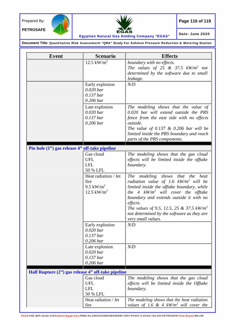
Page 116 of 119
Egyptian Natural Gas Holding Company “EGAS”
Prepared By: PETROSAFE
Date: June 2020
Document Title: Quantitative Risk Assessment “QRA” Study For Ashmon Pressure Reduction & Metering Station
EGAS.HSE.QRA.Study.018/Ashmon-Egypt.Gas.PRMS.No.006/2020/QRA/MG/MS/MY-DNV-PHAST.8.2/UAN.156,393-PETROSAFE-Final.Report-Rev.00
Event Scenario Effects 12.5 kW/m2 boundary with no effects.
The values of 25 & 37.5 kW/m2 not determined by the software due to small leakage.
Early explosion 0.020 bar 0.137 bar 0.206 bar
N/D
Late explosion 0.020 bar 0.137 bar 0.206 bar
The modeling shows that the value of 0.020 bar will extend outside the PRS fence from the east side with no effects outside. The value of 0.137 & 0.206 bar will be limited inside the PRS boundary and reach parts of the PRS components.
Pin hole (1”) gas release 4” off-take pipeline Gas cloud
UFL LFL 50 % LFL
The modeling shows that the gas cloud effects will be limited inside the offtake boundary.
Heat radiation / Jet fire 9.5 kW/m2
12.5 kW/m2
The modeling shows that the heat radiation value of 1.6 kW/m2 will be limited inside the offtake boundary, while the 4 kW/m2 will cover the offtake boundary and extends outside it with no effects. The values of 9.5, 12.5, 25 & 37.5 kW/m2 not determined by the software as they are very small values.
Early explosion 0.020 bar 0.137 bar 0.206 bar
N/D
Late explosion 0.020 bar 0.137 bar 0.206 bar
N/D
Half Rupture (2”) gas release 4” off-take pipeline Gas cloud
UFL LFL 50 % LFL
The modeling shows that the gas cloud effects will be limited inside the Offtake boundary.
Heat radiation / Jet fire
The modeling shows that the heat radiation values of 1.6 & 4 kW/m2 will cover the

Page 117 of 119
Egyptian Natural Gas Holding Company “EGAS”
Prepared By: PETROSAFE
Date: June 2020
Document Title: Quantitative Risk Assessment “QRA” Study For Ashmon Pressure Reduction & Metering Station
EGAS.HSE.QRA.Study.018/Ashmon-Egypt.Gas.PRMS.No.006/2020/QRA/MG/MS/MY-DNV-PHAST.8.2/UAN.156,393-PETROSAFE-Final.Report-Rev.00
Event Scenario Effects 9.5 kW/m2
12.5 kW/m2 offtake boundary and extend outside it with no effects. The values of 9.5, 12.5, 25 & 37.5 kW/m2 not determined by the software as they are very small values.
Early explosion 0.020 bar 0.137 bar 0.206 bar
N/D
Late explosion 0.020 bar 0.137 bar 0.206 bar
N/D
Full Rupture gas release 4” off-take pipeline Gas cloud
UFL LFL 50 % LFL
The modeling shows that the gas cloud will be limited inside the Offtake boundary with some extension outside from south side downwind.
Heat radiation / Jet fire 9.5 kW/m2
12.5 kW/m2
The modeling shows that the heat radiation values of 1.6 & 4 kW/m2 will cover the offtake boundary and extend outside it with no effects. The values of 9.5, 12.5, 25 & 37.5 kW/m2 not determined by the software as they are very small values.
Early explosion 0.020 bar 0.137 bar 0.206 bar
N/D
Late explosion 0.020 bar 0.137 bar 0.206 bar
N/D
Heat radiation / Fireball 9.5 kW/m2
12.5 kW/m2
N/D
The previous table shows that there is some of direct effects on PRMS workers, and as there is no direct effects on public around the PRMS or the off-take point. Therefore, it will be assumed that one person (as public) works as farmer for 1 hour / day light, And one operator (as worker) for operation / maintenance inside the PRS boundary for 2 hours / day light. (Refer to table 33).

Page 118 of 119
Egyptian Natural Gas Holding Company “EGAS”
Prepared By: PETROSAFE
Date: June 2020
Document Title: Quantitative Risk Assessment “QRA” Study For Ashmon Pressure Reduction & Metering Station
EGAS.HSE.QRA.Study.018/Ashmon-Egypt.Gas.PRMS.No.006/2020/QRA/MG/MS/MY-DNV-PHAST.8.2/UAN.156,393-PETROSAFE-Final.Report-Rev.00
Recommendations Regarding to the modeling scenarios and risk calculations to workers / public which found in Acceptable region (workers and public), therefore there are some points need to be considered to maintain the risk tolerability in its region and this will be describe in the following recommendations:
Recommendation Timeline Phases
Egypt Gas Remarks
• Ensure that
- All PRMS facilities specifications referred to the national and international codes and standards.
Design
- Inspection and maintenance plans and programs are according to the manufacturers guidelines to keep all facility parts in a good condition.
Operation
- All operations are according to standard operating procedures for the PRMS operations and training programs in-place for operators.
Operation
- Emergency shutdown detailed procedure including emergency gas isolation points at the PRMS and Off-Take Point in place.
Operation
- Surface drainage system is suitable for containment any odorant spillage.
Design
• Considering that all electrical equipment, facilities and connections are according to the hazardous area classification for natural gas facilities.
Design
• Preparing an emergency response plan and for the PRS including all scenarios in this study and other needs like: (Not Provided by EG)
Operation
- Firefighting brigades, mutual aids, emergency communications and fire detection / protection systems.
Operation
- Dealing with the external road in case of major fires.
Operation

Page 119 of 119
Egyptian Natural Gas Holding Company “EGAS”
Prepared By: PETROSAFE
Date: June 2020
Document Title: Quantitative Risk Assessment “QRA” Study For Ashmon Pressure Reduction & Metering Station
EGAS.HSE.QRA.Study.018/Ashmon-Egypt.Gas.PRMS.No.006/2020/QRA/MG/MS/MY-DNV-PHAST.8.2/UAN.156,393-PETROSAFE-Final.Report-Rev.00
Recommendation Timeline Phases
Egypt Gas Remarks
- First aid including dealing with the odorant according to the MSDS for it, with respect of means of water supply for emergency showers, eye washers and cleaning.
Operation
- Safe exits in building according to the modeling in this study, and to the PRS from other side beside the designed exit in layout provided.
Design
• Provide the site with SCBA “Self-Contained Breathing Apparatus (at least two sets) and arrange training programs for operators.
Operation
• Cooperation should be done with the concerned parties before planning for housing projects around the PRMS area.
Operation / Design / Construction
• Raising and pavement of the sub-route leading to the PRMS to a suitable level to protect the PRMS area against floodings.
Construction