Embed Size (px)
Citation preview

H
The effects of dirty connectors on laser based MMF links
IEEE 802.3z Plenary MeetingMarch, 1997
Irvine, CA
Mark Nowell & David CunninghamHewlett-Packard Laboratories,
Filton Road Bristol BS12 6QZ
H
Outline
Purpose of work
Dirty connectors
'real' dirt
'artificial' dirt
Splice defects
Conclusions
H
Purpose of this work
Concern has been raised about what the effects of dirty connectors and/or splices with defects have on system performance
it is perceived that this may be a problem for sources which underfill the fiber
Need to try to understandis this a real (likely) problem?if it is a real problem - how much of a
problem is it?

H
Specific issues addressed
In the 1/97 interim meeting the following specific issues were raised about dirty connectors:
systems which use a low mode fill are highly sensitive to dirty connectors while high mode fill is insensitive
measurements of loss for systems using low mode fill are difficult and require specialized equipment
This contribution will show:in a 'real world' test, dirt was seen to have little effect on systems
regardless of mode-fill or wavelengthwhen dirt did cause a penalty it was quite small (the short
wavelength, high mode fill, system generally experienced higher penalties).
If dirt is present (which it shouldn't be) it is easily detected using an EIA/TIA measurement standard which requires no more than a power meter
H
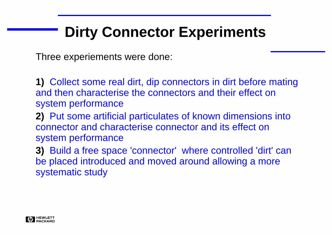
Dirty Connector Experiments
Three experiements were done:
1) Collect some real dirt, dip connectors in dirt before mating and then characterise the connectors and their effect on system performance2) Put some artificial particulates of known dimensions into connector and characterise connector and its effect on system performance3) Build a free space 'connector' where controlled 'dirt' can be placed introduced and moved around allowing a more systematic study

H
Real dirt
Dirt was collected from around our lab/office>100 dirty connectors were mated and
characterised foroverfilled loss at 850nm using LEDoverfilled loss at 1300nm using LEDunderfilled loss at 1300nm using laserreflections *effect on laser RIN *system penalty *
* not measured on every connector

H
Experimental set up
1300nmLED
850nmLED
1300nmHP CoaxialFP Laser
850nmFP
laser
12m 50MMF
Connectorunder test
Fiber shaker(system tests only)
Powermeter
VariableAttenuator
Receiver &Error
detector
RINMeasurement
OTDR
TemperatureRamping
(system tests only)
Fiber shaker and temperature ramping were used in system measurements to ensure modal noise was induced if present

H
Loss results
1300nm OFL loss (dB)
850nm OFL loss vs 1300nm OFL loss
0.01
0.1
1
10
0.01 0.1 1 10
850n
m O
FL
loss
(d
B)
1300nm OFL loss vs RML loss
0.01
0.1
1
10
0.01 0.1 1 101300nm OFL loss (dB)
1300
nm
RM
L lo
ss (
dB
)
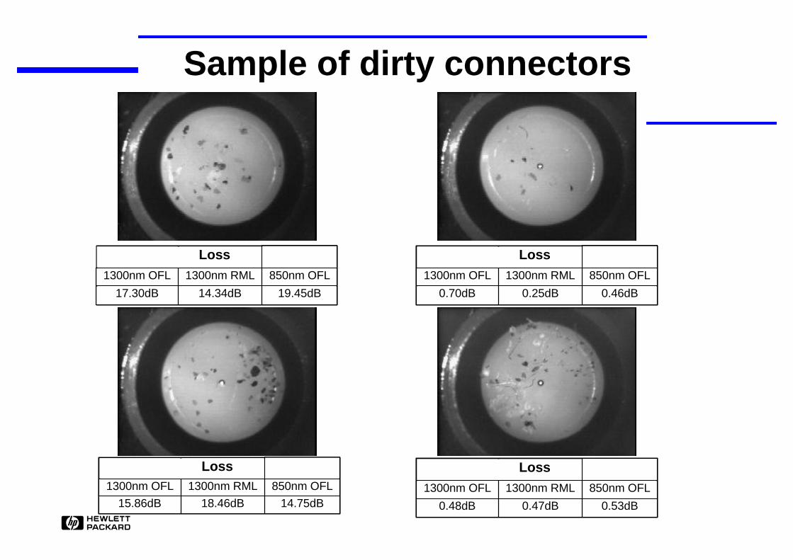
Before mating, each connector was checked to be dirty. Often dipping the connector in the dirt did not result in any dirt staying on the connector. A smear of finger grease was found to solve this problem. Therefore even this experiment is an extreme sample of the values that can be expected.
H
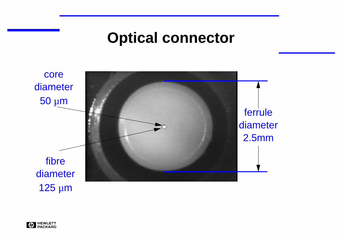
Optical connector
ferrulediameter2.5mm
corediameter
50 µm
fibrediameter125 µm
H
Sample of dirty connectors
Loss
1300nm OFL 1300nm RML 850nm OFL
17.30dB 14.34dB 19.45dB
Loss
1300nm OFL 1300nm RML 850nm OFL
0.70dB 0.25dB 0.46dB
Loss
1300nm OFL 1300nm RML 850nm OFL
15.86dB 18.46dB 14.75dB
Loss
1300nm OFL 1300nm RML 850nm OFL
0.48dB 0.47dB 0.53dB

H
Sample of dirty connectors: II
Loss
1300nm OFL 1300nm RML 850nm OFL
0.63dB 0.48dB 0.75dB
Loss
1300nm OFL 1300nm RML 850nm OFL
0.95dB 0.81dB 0.95dB
Loss
1300nm OFL 1300nm RML 850nm OFL
0.59dB 0.23dB 0.71dB
Loss
1300nm OFL 1300nm RML 850nm OFL
4.01dB 3.43dB 3.80dB

H
RML vs. OFL loss
1300nm OFL vs RML loss
0.01
0.1
1
10
0.01 0.1 1 10
1300nm OFL loss (dB)
1300
nm
RM
L lo
ss (
dB
)
Loss measured with an RML source or OFL source were similar.
shaded area would be considered in specification if measured with an LED
µOFL lossRML loss
.
= 093
H
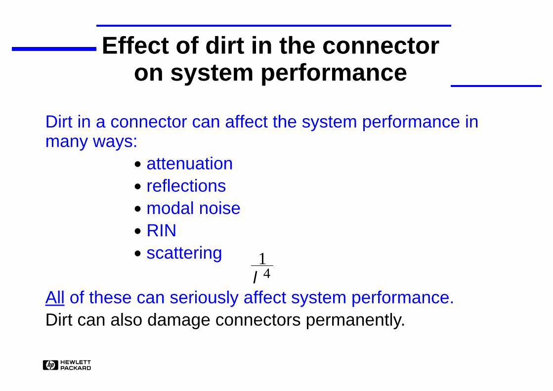
Effect of dirt in the connector on system performance
Dirt in a connector can affect the system performance in many ways:
attenuationreflectionsmodal noiseRINscattering
All of these can seriously affect system performance.Dirt can also damage connectors permanently.
∝ 14λ

H
Power penalties
0.01
0.1
1
10
0.01 0.1 1 10
1300nm OFL loss (dB)
1300
nm
RM
L lo
ss (
dB
)
1300nm OFL
1300nm RML
850nm OFL
850nm 1300nm
0.37 0.71 0.43 0.6 0.10.3 0.68 0.41 0.1 0.12.20 2.30 2.27 0.4 0.10.83 1.06 0.73 - 0.11.11 2.0 1.26 0.5 0.25
Loss (dB) Penalty (dB)
850nm source for system measurements was FP laser which overfilled the fiber. 1300nm source was HP coaxial laser which underfilled the fiber
Power penalties were measured using the modal noise procedure which includes temperature ramping and fiber shaking to ensure modal noise was induced if present.
Reference curves were measured with clean connectors.
measured points shown in red
H
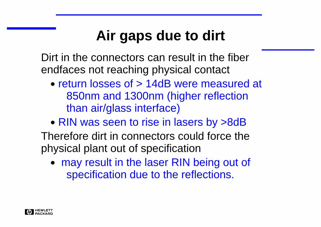
Air gaps due to dirt
Dirt in the connectors can result in the fiber endfaces not reaching physical contact
return losses of > 14dB were measured at 850nm and 1300nm (higher reflection than air/glass interface)
RIN was seen to rise in lasers by >8dBTherefore dirt in connectors could force the physical plant out of specification
may result in the laser RIN being out of specification due to the reflections.

H
What to do if you have dirty connectors
To clean connectors ideally you would use a lint-free cloth and some cleaning solution (isopropyl alcohol)
BUTyou could just wipe it with your finger (not a recommendation!)
1300nm OFL
1300nm RML
850nm OFL
1300nm OFL
1300nm RML
850nm OFL
6.3 6.4 6.1 0.05 0.04 0.0715.47 10.9 16.0 0.03 0.05 0.0717.87 17.77 19.48 0.06 0.05 0.082.0 2.0 2.3 0.07 0.06 0.090.89 0.51 1.02 0.42 0.59 0.6712.2 11.97 15.76 0.48 0.50 0.5415.84 18.46 14.75 0.14 0.06 0.06
Loss with dirt present(dB)
Loss after wipe with finger (dB)

H
Connector damage
Connectors can become permanently damaged by dirt. Once damaged they have to be replaced.
During this experiment, the patchcords had to be replaced 4 times due to damage
This would be a major problem in an installation which is why keeping connectors clean is standard practice.

H
Artificial dirt
To increase the chance of seeing a small speck of dirt in the beam, fused alumina particulates (particle mean size 5µm) were mixed with index matching gel and smeared on the connector endface before mating.
1300nm OFL
1300nm RML
850nm OFL
850nm 1300nm
0.81 1.31 0.67 1.5 1.0
Loss (dB) Penalty (dB)
H
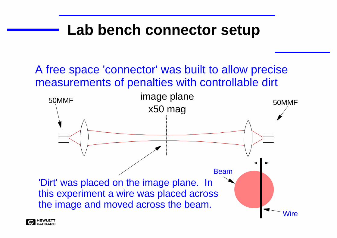
Lab bench connector setup
A free space 'connector' was built to allow precise measurements of penalties with controllable dirt
image planex50 mag
Beam
Wire
50MMF 50MMF
'Dirt' was placed on the image plane. In this experiment a wire was placed across the image and moved across the beam.
H
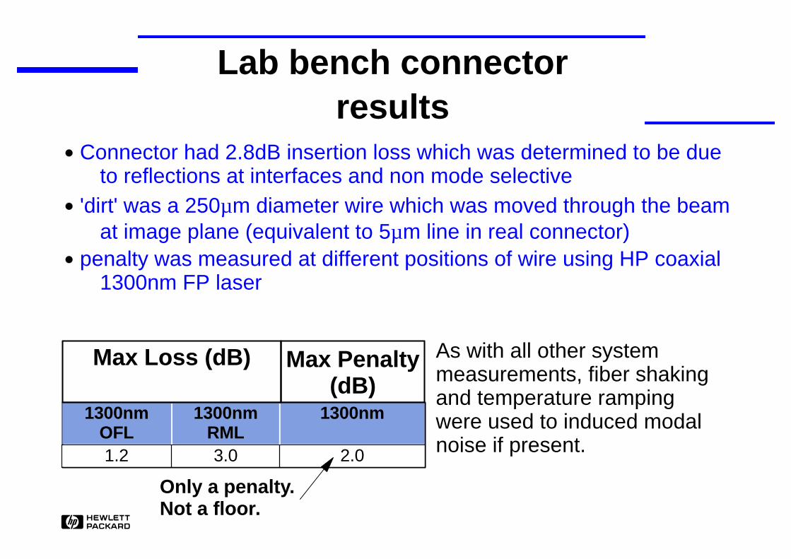
Lab bench connectorresults
Connector had 2.8dB insertion loss which was determined to be due to reflections at interfaces and non mode selective
'dirt' was a 250µm diameter wire which was moved through the beam at image plane (equivalent to 5µm line in real connector)
penalty was measured at different positions of wire using HP coaxial 1300nm FP laser
1300nm OFL
1300nm RML
1300nm
1.2 3.0 2.0
Max Loss (dB) Max Penalty (dB)
Only a penalty. Not a floor.
As with all other system measurements, fiber shaking and temperature ramping were used to induced modal noise if present.

H
Measurement of cable plant (dirty connectors)
EIA/TIA OFSTP-14A has just closed ballotaddresses measuring the cable plant loss
specifically for laser based systemsrecommends using source with class of launch
similar to that of the system transmitterimplies that the network can be diagnosed for
lossy connectors using only the network transmitter and a power meter

H
Fusion Splicing
To obtain a good fusion splice you must have:perpendicular cleave of the fiber endsclean ends before fusing
Modern cleaversprovide very consistent perpendicular cleavesare automated (manual devices are less
consistent)come integrated onto many modern fusion
splicers

H
Fusion SplicingModern fusion splicers
use short burst of arc to plasma clean the fiber endfaces - very efficient form of cleaning.
automated and programmable - can be optimised for SMF or MMF.
allow re-fusing of splice to improve and splices before splice protection is added.
primarily designed for SMF usersin SMF the kind of defects we are worried
about would severely affect the system therefore the possibility of their occurance is designed out.

H
Splices defectsOver 50 fusion splices were made to try to observe the types of defects we are worried about.I was only able to make bad splices if I:
turned off pre-fusion cleaning and eitherdeliberately introduced dirtmade a bad manual cleave (i.e. with penknife)
Resultswas unable to make a splice which was in spec for loss and which caused a
penalty of > 0.25 dB if bubbles were present re-fusing always reduced their loss
a bubble which induced 14dB loss was reduced to 0.8 dB loss through re-fusing (system penalty was then measured to be 0.2dB)
ConclusionIt is VERY difficult to make a bad splice which is within spec and will cause system degradation using common installation practices

H
Summary
>100 dirty connectors made and characterisedno significant penalties measureddirt can result in penalties due to:
attenuationreflectionsmodal noiseRINscattering
if dirt is present and causing problems it can easily be solved (as long as it hasn't caused physical damage).

H
Summary
It is conceivable that there may exist a pathalogical piece of dirt which can cause various system penalties BUT
it is not specific to any wavelength or launchit has a very low probability of occuring

H
Conclusion
Dirty connectors have a very low probability of being both undetected and capable of causing significant system penalties.
This is not a real world issue.