Embed Size (px)
Citation preview

The Effect of X Bracing System Addition in
Reinforced Concrete Structure as Earthquake
Resistant Element
Hendramawat Aski Safarizki
Universitas Veteran Bangun Nusantara
Sukoharjo, Indonesia
Abstract—The Indonesian government has tried to
overcome the emergence of casualties by making regulations
about earthquake resistant structures. Various ways are used
to reduce building damage due to the earthquake. One of them
is by adding bracing system as lateral stiffeners. In this study,
an analysis was conducted between concrete buildings without
X braces and after the addition of X braces by using static
equivalent analysis based on SNI 1726-2012. Then a
comparison is made between the displacements that occur to
determine the effectiveness of using X braces on reinforced
concrete structures. The aim of this study is to evaluating the
effect of the earthquake on multi storied reinforced concrete
structure before and after using X bracing system. The seismic
effect like shear force, story drift, and displacement in
reinforced concrete structure before and after using X bracing
system was evaluated. The result shows that shear force on
each floor was increase before and after the addition of braces
on each floor between 8-13%. It appears that the displacement
will decrease significantly with the addition of X bracing. The
floor displacement before and after the addition of bracing X
reduce evenly almost 50%.
Keywords—bracing, displacement, earthquake, shear force
I. INTRODUCTION
Indonesia is an earthquake-prone area because it is located at the confluence of the Earth's plate. Earthquake events in Indonesia often cause losses both in terms of material and casualties. The Indonesian government has tried to overcome the emergence of casualties by making regulations about earthquake resistant structures. Earthquake Resistance Planning Standards for Building Structure and Non-Building that applies today are SNI 1726-2012. SNI 1726-2012 refers to earthquake with a 2500 year return period in contrast to SNI 1726-2002 which is based on an earthquake with a 500-year return period. In SNI 1726-2012 the Indonesia territory was mapped based on differences in peak ground acceleration (PGA).
Various ways are used to reduce building damage due to the earthquake. One of them is by adding bracing system as lateral stiffeners. Steel braces can be used as lateral supports in static nonlinear earthquakes based on FEMA 356 and FEMA 440 [1]. Various braces can be used as lateral stiffeners such as the X type, V type, inverted V type and Knee type bracing. The X braces and Knee can reduce lateral forces more effective compared to other types of bracing system [2]. X-Bracing effectively also increases lateral stiffness and reduces displacement due to earthquake loads [3]. After the analysis of the structure with different types of
structural systems, the displacement of the structure decreases after the application of bracing system [4].
In this study, an analysis was conducted between concrete buildings without X braces and after the addition of X braces by using static equivalent analysis based on SNI 1726-2012. Then a comparison is made between the displacements that occur to determine the effectiveness of using X braces on reinforced concrete structures. 1. Evaluating the effect of the earthquake on multi storied reinforced concrete structure before and after using X bracing system. 2. Evaluating the seismic effect like shear force, story drift, and displacement in reinforced concrete structure before and after using X bracing system. 3. Determine the effectiveness of using X bracing on reinforced concrete structures.
II. METHODS
This study uses the equivalent static analysis method based on SNI 1726-2012 using ETABS software. The analysis is performed by first calculating the weight of the structure as the basis of static equivalent analysis. Effective seismic structure weight must include all dead loads, live loads and other loads acting on the structure. The location and type of soil also need to be considered in the analysis process.
III. RESULTS AND DISCUSSION The structure model must be made in such a way as to
determine the structural element force and the displacement of the structure from the applied load and all displacements imposed. The model must include the rigidity and strength of the elements that are significant to the distribution of forces and deformations in the structure and represent the distribution of mass and spatial rigidity in the entire structure [5].
The structure being reviewed is a five-story concrete structure as shown in Figure 1, located in Sukoharjo under moderate soil conditions. The structure is used as a school building. According to SNI 1726-2012 school building is included in the Risk Category IV.
Seismic variables are obtained from the Indonesian spectra design application by entering the location of the building and the appropriate soil conditions. Seismic variables are reviewed according to the location and type of soil as shown in Figure 2.
International Conference on Applied Science and Engineering (ICASE 2018)
Copyright © 2018, the Authors. Published by Atlantis Press. This is an open access article under the CC BY-NC license (http://creativecommons.org/licenses/by-nc/4.0/).
Advances in Engineering Research, volume 175
129
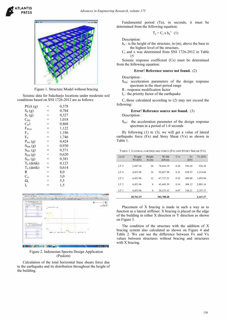
Figure 1. Structure Model without bracing
Seismic data for Sukoharjo locations under moderate soil conditions based on SNI 1726-2012 are as follows:
PGA (g) = 0,378
SS (g) = 0,784
S1 (g) = 0,327
CRS = 1,018
CR1 = 0,868
FPGA = 1,122
FA = 1,186
FV = 1,746
PSA (g) = 0,424
SMS (g) = 0,930
SM1 (g) = 0,571
SDS (g) = 0,620
SD1 (g) = 0,381
T0 (detik) = 0,123
TS (detik) = 0,614
R = 8,0
Cd = 3,0
Ω0 = 5,5
Ie = 1,5
Figure 2. Indonesian Spectra Design Application (Puskim)
Calculation of the total horizontal base shears force due to the earthquake and its distribution throughout the height of the building.
Fundamental period (Ta), in seconds, it must be determined from the following equation:
Ta = Ct x hnx (1)
Description: hn : is the height of the structure, in (m), above the base to
the highest level of the structure, Ct and x was determined from SNI 1726-2012 in Table
15 Seismic response coefficient (Cs) must be determined
from the following equation:
Error! Reference source not found. (2)
Description : SDS: acceleration parameters of the design response
spectrum in the short period range R : response modification factor Ie : the priority factor of the earthquake
Cs those calculated according to (2) may not exceed the following:
Error! Reference source not found. (3) Description :
SD1: the acceleration parameter of the design response spectrum in a period of 1.0 seconds
By following (1) to (3), we will get a value of lateral earthquake force (Fx) and Story Shear (Vx) as shown in Table 1.
TABLE 1. LATERAL EARTHQUAKE FORCE (FX) AND STORY SHEAR (VX)
Level Weight
Wi (kN)
Height
hi (m)
Wi hik
(kN.m)
Cvx Fx
(kN)
Vx (kN)
LT 5
2,947.36 20
78,436.19 0.26 556.28 556.28
LT 4
4,453.96 16
92,827.98 0.31 658.35 1,214.64
LT 3
4,453.96 12
67,737.21 0.22 480.40 1,695.04
LT 2
4,453.96 8
43,445.59 0.14 308.12 2,003.16
LT 1
4,453.96 4
20,333.52 0.07 144.21 2,147.37
20,763.19
302,780.48 2,147.37
Placement of X bracing is made in such a way as to function as a lateral stiffener. X bracing is placed on the edge of the building in either X direction or Y direction as shown on Figure 3.
The condition of the structure with the addition of X bracing system also calculated as shown on Figure 4 and Table 2. We can see the difference between Fx and Vx values between structures without bracing and structures with X bracing.
Advances in Engineering Research, volume 175
130

Figure 3. Placement of Bresing on X Direction
TABLE 2. LATERAL EARTHQUAKE FORCE (FX) AND STORY SHEAR (VX)
STRUCTURE WITH X BRACING
Level Weight
Wi (kN)
Height
hi (m)
Wi hik
(kN.m)
Cvx Fx
(kN)
Vx (kN)
LT 5 2,968.92 20 79,010.01 0.26 838.41 838.41
LT 4 4,475.52 16 93,277.38 0.31 989.81 1,828.22
LT 3 4,475.52 12 68,065.13 0.22 722.27 2,550.49
LT 2 4,475.52 8 43,655.92 0.14 463.25 3,013.74
LT 1 4,475.52 4 20,431.96 0.07 216.81 3,230.56
20,871.00 304,440.40 3,230.56
The analysis is continued by performing load combination to get the seismic effect such as shear force, story drift, and displacements in reinforced concrete structure before and after using X bracing system.
Shear force on each floor as shown in Figure 5. It can be seen that there is an increase in shear force before and after the addition of braces on each floor between 8-13%.
Figure 4. Structure Model with X bracing
Figure 5. Shear Force before and after addition of braces
Lateral shear force from the earthquake will cause floor displacement as shown in Figure 6. It appears that the displacement will decrease significantly with the addition of X bracing. The floor displacement before and after the addition of bracing X reduce evenly almost 50% as shown in the Table 3 and Figure 7.
TABLE 3. FLOOR DISPLACEMENET
FLOOR Displacement (m) Derivation
% Without Bracing Using X Bracing
STORY1 0.0214 0.0101 47.20
STORY2 0.0466 0.0226 48.50
STORY3 0.0680 0.0345 50.74
STORY4 0.0832 0.0445 53.49
STORY5 0.0905 0.0513 56.69
Story drift that occurs also decreases along with the reduction in diplacement after adding the X bracing. Story drift decrease on each floor between 46,94% - 92,59% as shown in the Table 4.
Figure 6. Displacement
Advances in Engineering Research, volume 175
131
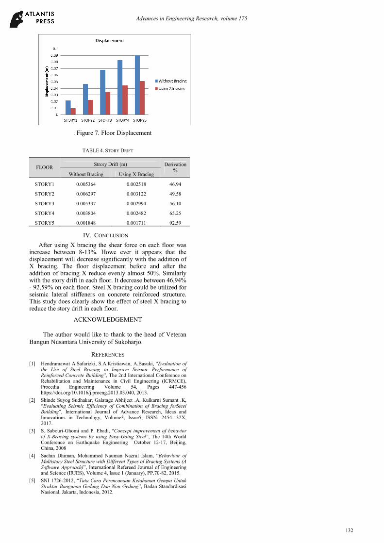
. Figure 7. Floor Displacement
TABLE 4. STORY DRIFT
FLOOR Strory Drift (m) Derivation
% Without Bracing Using X Bracing
STORY1 0.005364 0.002518 46.94
STORY2 0.006297 0.003122 49.58
STORY3 0.005337 0.002994 56.10
STORY4 0.003804 0.002482 65.25
STORY5 0.001848 0.001711 92.59
IV. CONCLUSION
After using X bracing the shear force on each floor was increase between 8-13%. Howe ever it appears that the displacement will decrease significantly with the addition of X bracing. The floor displacement before and after the addition of bracing X reduce evenly almost 50%. Similarly with the story drift in each floor. It decrease between 46,94% - 92,59% on each floor. Steel X bracing could be utilized for seismic lateral stiffeners on concrete reinforced structure. This study does clearly show the effect of steel X bracing to reduce the story drift in each floor.
ACKNOWLEDGEMENT
The author would like to thank to the head of Veteran
Bangun Nusantara University of Sukoharjo.
REFERENCES
[1] Hendramawat A.Safarizki, S.A.Kristiawan, A.Basuki, “Evaluation of the Use of Steel Bracing to Improve Seismic Performance of Reinforced Concrete Building”, The 2nd International Conference on Rehabilitation and Maintenance in Civil Engineering (ICRMCE), Procedia Engineering Volume 54, Pages 447-456 https://doi.org/10.1016/j.proeng.2013.03.040, 2013.
[2] Shinde Suyog Sudhakar, Galatage Abhijeet .A, Kulkarni Sumant .K, “Evaluating Seismic Efficiency of Combination of Bracing forSteel Building”, International Journal of Advance Research, Ideas and Innovations in Technology, Volume3, Issue5, ISSN: 2454-132X, 2017.
[3] S. Sabouri-Ghomi and P. Ebadi, “Concept improvement of behavior of X-Bracing systems by using Easy-Going Steel”, The 14th World Conference on Earthquake Engineering October 12-17, Beijing, China, 2008
[4] Sachin Dhiman, Mohammed Nauman Nazrul Islam, “Behaviour of Multistory Steel Structure with Different Types of Bracing Systems (A Software Approach)”, International Refereed Journal of Engineering and Science (IRJES), Volume 4, Issue 1 (January), PP.70-82, 2015.
[5] SNI 1726-2012, “Tata Cara Perencanaan Ketahanan Gempa Untuk Struktur Bangunan Gedung Dan Non Gedung”, Badan Standardisasi Nasional, Jakarta, Indonesia, 2012.
Advances in Engineering Research, volume 175
132