Embed Size (px)
Citation preview
The Effect of Wind catcher Geometry on the Indoor Thermal Behavior
M. Hossein Ghadiri1, N. Lukman N. Ibrahim2, R. Aayani3 1, 2
Department of Architecture, Universiti Kebangsaan Malaysia (UKM) 3Department of Mechanical Engineering, Shiraz University, Shiraz, Iran
ABSTRACT: The wide spread use of air conditioning to meet the high load of cooling for buildings in hot - arid
climate regions has become a real problem. Since these systems have a high impact on the peak electricity load, and cause environmental problem associated with ozone depletion, global warming, urban heat island and deterioration of the indoor air quality. Recently, as means to reduce energy consumption of air conditioning systems, wind towers have been used as an alternative solution to meet summer thermal cooling. The ventilation structures called "Badgirs" or wind towers were the most important means by which the interior was cooled in Iranian desert region. These wind towers or wind catchers can be found in Iranian cities with hot-dry and hot-humid climates. This paper is a synopsis of the results of a research on the wind catcher element in the traditional architecture of Iran. A review of the wind towers' characteristics with emphasis on their morphology is provided and categorization of the wind towers based on their physical attributes and parameters are thus proposed. This paper also presents a limited thermal simulation results which shows the influence of different wind catcher’s plan geometry on the indoor air temperature. The simulations carried out using a 3-D computational fluid dynamics (CFD) software called FLUENT, demonstrate the effect of two different square wind catchers on the indoor thermal performance. Conference theme: sustainability issues. Keywords— Wind Catcher, Natural Cooling System, Wind catcher’s Blade, fluent software.
INTRODUCTION
Wind tower is one of the vernacular elements which are widely used in hot, hot dry and hot humid climates especially in countries like Iran [1]. They are tall towers on the building’s roof tops with several vents to capture wind for cooling the interior spaces. This is one of the most beautiful connections between the architectural design and natural environment for conserving energy on the basis of sustainability principle [1]. Wind catcher openings are usually positioned facing desired wind directions. Wind catcher functions based on pressure difference between leeward and windward which is positive in inlet opening and negative in outlet vent. Venturi effect causes air to come down through the wind catcher channel at a higher velocity and lower pressure. The desert areas experience cool nights and hot days and the temperature difference between night and day is high. Therefore, during the night when the outdoor temperature is low the walls temperature falls down and helps to cool the interior space during the next day. Wind catchers operate well when the wind velocity is more than 3 m/s. When the wind velocity is less than 3 m/s, the heat released by the wind catcher heats up the air inside it and drives the heat upward and outside the building.
PREVIOUS WORKS
Recently huge attention has been drawn towards sustainability with the aim to counter with energy crisis. There are several reports available about the performance of wind catcher and the design of modern wind catchers [2]. Elmualim has investigated the performance of wind catchers by different modeling techniques including wind tunnel testing, salt bath, computational fluid dynamics (CFD) [3]. Elmualim and Awbi [4] also carried out experimental investigation and CFD simulations to evaluate the performance of square and circular plan wind catchers. Results show that the efficiency of four-sided wind catcher is much higher than that of the circular one under the same wind speed. They explained that this is due to the sharp edges of the square tower creating a large region of flow separation and higher pressure difference across the device. Bahadori detected the pressure difference between the inlet and outlet opening by conducting flow fluid analysis. He also designed two new wind catchers which utilize evaporation cooling through wet surfaces and wet columns [5-7]. Yasmina Bouchahm analyzed the performance of wind catcher in an actual office building in Ouargla city of Algeria (hot and arid climate). In the investigation, the interior air temperature and humidity of air are measured and compared with the outdoor values [8]. Measurements were performed under two conditions ―with and without evaporative potential‖. A mathematical model of the wind tower was developed and validated using the measured data. The amount of heat absorbed in the process of water evaporation is very high in comparison with other modes of heat transfer common in building. This investigation by Bouchman to demonstrates the efficiency of wind tower with passive evaporative cooling strategy in hot and arid
regions of Algeria. So the wind tower with no humidification provides only sensible cooling. Therefore humidification strategy would be required in this condition. When water is introduced into the wind catcher system, evaporative cooling occurs. As air flows through the conduits, water evaporates into the air stream adiabatically, and the moisture content or humidity ratio of air increases by dividing the height of the column into smaller sections, surface heat and mass transfer will increase if constant moister content within each section is assumed. Thus, much lower temperature and higher humidity would be obtained. A 500mm square wind catcher system connected to the room has been modeled for different wind speeds in the range of 0.5–6 m/s and four different wind directions [9]. The numerical results generally agree with the published experimental results of a wind tunnel experiment. The numerical results demonstrate that the wind catcher performance is greatly influenced by the external wind speed and direction with respect to the wind catcher quadrants. In all cases studied, the maximum velocity of air entering the room is close to the external wind speed and the wind catcher system is found to be an efficient way of channeling fresh air into the room. The study also shows that the airflow rate of the air entering the room increases with the wind speed and slightly decreases with the wind incidence angle when the wind speed is lower than 3 m/s. The performance of a cooling tower was studied for different climatic regions of Jordan, such as the desert areas, Jordan valley (Ghor) and Aqaba, where air conditioning is needed most [10]. It was found that under those climates, the height of the tower necessary to create proper air flow is less than 9m. This is in contrast to the traditional design which may reach up to 15m in height. The common behavior for the three zones is that relative humidity of air leaving the tower steadily increases with the height until a certain value of height (about 9m) is reached. Any further increase in height will not significantly increase humidity because air approaches saturation.
CATEGORIZATION OF WIND CATCHERS BASED ON ORIENTATION
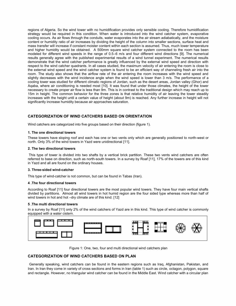
Wind catchers are categorized into five groups based on their direction (figure 1).
1. The one directional towers
These towers have sloping roof and each has one or two vents only which are generally positioned to north-west or north. Only 3% of the wind towers in Yazd were unidirectional [11].
2. The two directional towers
This type of tower is divided into two shafts by a vertical brick partition. These two vents wind catchers are often referred to base on direction, such as north-south towers. In a survey by Roaf [11], 17% of the towers are of this kind in Yazd and all are found on the ordinary houses.
3. Three-sided wind-catcher
This type of wind-catcher is not common, but can be found in Tabas (Iran).
4 .The four directional towers
According to Roaf [11] four directional towers are the most popular wind towers. They have four main vertical shafts divided by partitions. Almost all wind towers in hot humid region are the four sided type whereas more than half of wind towers in hot and hot –dry climate are of this kind. [12]
5 .The multi directional towers
In a survey by Roaf [11] only 2% of the wind catchers of Yazd are in this kind. This type of wind catcher is commonly equipped with a water cistern.
Figure 1: One, two, four and multi directional wind catchers plan
CATEGORIZATION OF WIND CATCHERS BASED ON PLAN
Generally speaking, wind catchers can be found in the eastern regions such as Iraq, Afghanistan, Pakistan, and
Iran. In Iran they come in variety of cross sections and forms in Iran (table 1) such as circle, octagon, polygon, square
and rectangle. However, no triangular wind catcher can be found in the Middle East. Wind catcher with a circular plan
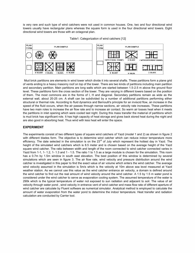
is very rare and such type of wind catchers were not used in common houses. One, two and four directional wind
towers usually have rectangular plans whereas the square form is used in the four directional wind towers. Eight
directional wind towers are those with an octagonal plan.
Table1: Categorization of wind catchers [12]
Mud brick partitions are elements in wind tower which divide it into several shafts. These partitions form a plane grid
of vents ending to a heavy masonry roof on top of the tower. There are two kinds of partitions including main partition
and secondary partition. Main partitions are long walls which are started between 1.5-2.5 m above the ground floor
level. These partitions form the cross section of the tower. They are varying in different towers based on the position
of them. The most commons are in the forms of I, H and diagonal. Secondary partitions remain as wide as the
external wall, about 20-25 cm. A shaft can be subdivided by a number of additional partitions performing either
structural or thermal role. According to fluid dynamics and Bernoulli's principle for an inviscid flow, an increase in the
speed of the fluid occurs, when the air passes through narrow sections, air velocity rate increases. These partitions
have two main roles to increase the air flow rate and to increase air contact. So warm air losses heat when it meets
the partitions in inlet opening which were cooled last night. During this mass transfer the material of partitions which
is mud brick has significant role. It has high capacity of heat storage and gives back stored heat during the night and
are also good in absorbing heat. Thus wind with less heat will enter the space.
EXPERIMENT
The experiments consist of two different types of square wind catchers of Yazd (model 1 and 2) as shown in figure 2
with different blades form. The objective is to determine wind catcher which can reduce indoor temperature more
efficiency. The date selected in the simulation is on the 23rd
of July which represent the hottest day in Yazd. The
height of the simulated wind catchers which is 8.5 meter and is chosen based on the average height of the Yazd
square wind catcher. The ratio between width and length of the room connected to wind catcher connected varies in
Yazd from 1-1, 1- 1.2, 1- 1.3 and 1 - 1.5. The ratio 1 to 1.5 as a large module is chosen for the simulation. This room
has a 0.7m by 1.5m window in south east elevation. The best position of this window is determined by several
simulations which are seen in figure 3. The air flow rate, wind velocity and pressure distribution around the wind
catcher is investigated in this paper to find the exact value of air volume which enters the wind catcher. The average
wind velocity assumed in the simulation is 5m/s which is the velocity at 10m above sea level measured at Yazd
weather station. As we cannot use this value as the wind catcher entrance air velocity, a domain is defined around
the wind catcher to find out the real amount of wind velocity around the wind catcher. A 1.5 by 1.5 m water pond is
considered under the wind catcher to serve as evaporation cooling system. The assumed temperature of the water is
290k which is the typical temperature of water not exposed to sun radiation and adjacent to soil. The value of air
velocity through water pond , wind velocity in entrance vent of wind catcher and mass flow rate of different aperture of
wind catcher are calculate by Fluent software as numerical simulator. Analytical method is employed to calculate the
amount of water evaporation from the water pond to determine the indoor temperature. Heat transfer and radiation
calculation are conducted by Carrier tool.
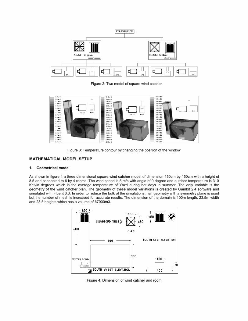
Figure 2: Two model of square wind catcher
Figure 3: Temperature contour by changing the position of the window
MATHEMATICAL MODEL SETUP
1. Geometrical model
As shown in figure 4 a three dimensional square wind catcher model of dimension 150cm by 150cm with a height of 8.5 and connected to 6 by 4 rooms. The wind speed is 5 m/s with angle of 0 degree and outdoor temperature is 310 Kelvin degrees which is the average temperature of Yazd during hot days in summer. The only variable is the geometry of the wind catcher plan. The geometry of these model variations is created by Gambit 2.4 software and simulated with Fluent 6.3. In order to reduce the bulk of the simulations, half geometry with a symmetry plane is used but the number of mesh is increased for accurate results. The dimension of the domain is 100m length, 23.5m width and 28.5 heights which has a volume of 67000m3.
Figure 4: Dimension of wind catcher and room
2. Mesh design and boundary condition
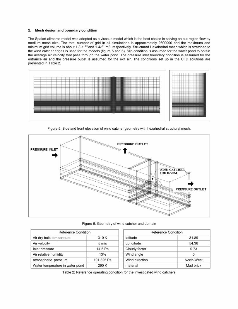
The Spalart allmaras model was adopted as a viscous model which is the best choice in solving an out region flow by medium mesh size. The total number of grid in all simulations is approximately 2600000 and the maximum and
minimum grid volume is about 1.8 𝑒−06and 1.4𝑒01 m3, respectively. Structured Hexahedral mesh which is stretched to the wind catcher edges is used for the models (figure 5 and 6). Slip condition is assumed for the water pond to obtain the average air velocity that pass through the water pond. The pressure inlet boundary condition is assumed for the entrance air and the pressure outlet is assumed for the exit air. The conditions set up in the CFD solutions are presented in Table 2.
Figure 5: Side and front elevation of wind catcher geometry with hexahedral structural mesh.
Figure 6: Geometry of wind catcher and domain
Reference Condition
Reference Condition
Air dry bulb temperature 310 K latitude 31.89
Air velocity 5 m/s Longitude 54.36
Inlet pressure 14.5 Pa Cloudy factor 0.73
Air relative humidity 13% Wind angle 0
atmospheric pressure 101.325 Pa Wind direction North-West
Water temperature in water pond 290 K material Mud brick
Table 2: Reference operating condition for the investigated wind catchers
GOVERNING EQUATIONS IN ANALYTICAL METHOD
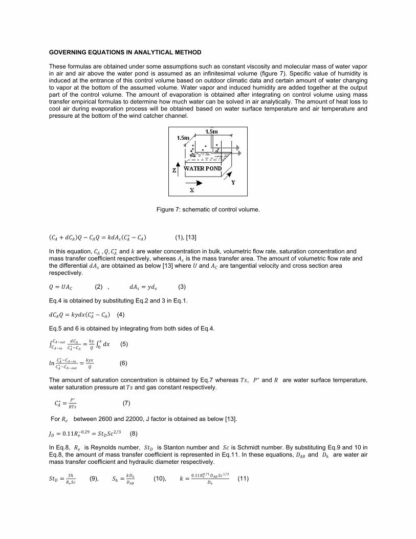
These formulas are obtained under some assumptions such as constant viscosity and molecular mass of water vapor in air and air above the water pond is assumed as an infinitesimal volume (figure 7). Specific value of humidity is induced at the entrance of this control volume based on outdoor climatic data and certain amount of water changing to vapor at the bottom of the assumed volume. Water vapor and induced humidity are added together at the output part of the control volume. The amount of evaporation is obtained after integrating on control volume using mass transfer empirical formulas to determine how much water can be solved in air analytically. The amount of heat loss to cool air during evaporation process will be obtained based on water surface temperature and air temperature and pressure at the bottom of the wind catcher channel.
Figure 7: schematic of control volume.
𝐶𝐴 + 𝑑𝐶𝐴 𝑄 − 𝐶𝐴𝑄 = 𝑘𝑑𝐴𝑠 𝐶𝐴∗ − 𝐶𝐴 (1), [13]
In this equation, 𝐶𝐴 ,𝑄,𝐶𝐴 ∗ and 𝑘 are water concentration in bulk, volumetric flow rate, saturation concentration and
mass transfer coefficient respectively, whereas 𝐴𝑠 is the mass transfer area. The amount of volumetric flow rate and
the differential 𝑑𝐴𝑠 are obtained as below [13] where 𝑈 and 𝐴𝐶 are tangential velocity and cross section area
respectively.
𝑄 = 𝑈𝐴𝐶 (2) , 𝑑𝐴𝑠 = 𝑦𝑑𝑥 (3)
Eq.4 is obtained by substituting Eq.2 and 3 in Eq.1.
𝑑𝐶𝐴𝑄 = 𝑘𝑦𝑑𝑥 𝐶𝐴∗ − 𝐶𝐴 (4)
Eq.5 and 6 is obtained by integrating from both sides of Eq.4.
𝑑𝐶𝐴
𝐶𝐴∗−𝐶𝐴
=𝑘𝑦
𝑄
𝐶𝐴−𝑜𝑢𝑡
𝐶𝐴−𝑖𝑛 𝑑𝑥𝑥
0 (5)
𝑙𝑛𝐶𝐴∗−𝐶𝐴−𝑖𝑛
𝐶𝐴∗−𝐶𝐴−𝑜𝑢𝑡
=𝑘𝑦𝑥
𝑄 (6)
The amount of saturation concentration is obtained by Eq.7 whereas 𝑇𝑠, 𝑃∗ and 𝑅 are water surface temperature,
water saturation pressure at 𝑇𝑠 and gas constant respectively.
𝐶𝐴∗ =
𝑃∗
𝑅𝑇𝑠 (7)
For 𝑅𝑒 between 2600 and 22000, J factor is obtained as below [13].
𝐽𝐷 = 0.11𝑅𝑒−0.29 = 𝑆𝑡𝐷𝑆𝑐
2 3 (8)
In Eq.8, 𝑅𝑒 is Reynolds number, 𝑆𝑡𝐷 is Stanton number and 𝑆𝑐 is Schmidt number. By substituting Eq.9 and 10 in
Eq.8, the amount of mass transfer coefficient is represented in Eq.11. In these equations, 𝐷𝐴𝐵 and 𝐷 are water air
mass transfer coefficient and hydraulic diameter respectively.
𝑆𝑡𝐷 =𝑆
𝑅𝑒𝑆𝑐 (9), 𝑆 =
𝑘𝐷
𝐷𝐴𝐵 (10), 𝑘 =
0.11𝑅𝑒0.71𝐷𝐴𝐵 𝑆𝑐
1 3
𝐷 (11)
Stanton number is obtained as Eq.12. For flow in a pipe or tube, the Reynolds number is generally defined as Eq.12. For shapes such as squares, rectangular or annular ducts the characteristic dimension for internal flow situations is taken to be the hydraulic diameter, Dh, defined as Eq.14.
𝑆𝑐 =𝑣
𝐷𝐴𝐵 (12), 𝑅𝑒 =
𝜌𝑈𝐷
𝜇 (13), 𝐷 =
4𝐴𝐶
𝑃 (14)
In these equations,𝑣, 𝜌, 𝜇, 𝑈, 𝐴𝐶 and 𝑃 are kinematic viscosity, air density, dynamic viscosity of the fluid, tangential
velocity, cross section area and perimeter respectively. Water-air mass transfer coefficient is obtained by Eq.15 whereas 𝑃 is pressure and 𝑇𝑠 is water surface temperature [14].
𝐷𝐴𝐵 =0.926
𝑃
𝑇𝑠2.5
𝑇𝑠+245 (15)
By substituting the amount of Eq.12-15 in Eq.11, the amount of k is achieved so the amount of 𝐶𝐴−𝑜𝑢𝑡 in Eq.6 is
acquired. Water vapor mass flow rate in air is represented in Eq.16 where M is molecular weight. The amount of heat exchange is obtained in Eq.17 where 𝑓𝑔 is enthalpy of phase change.
𝐶𝐴−𝑜𝑢𝑡 × 𝑄 × 𝑀 = 𝑚 𝑤𝑎𝑡𝑒𝑟 𝑖𝑛 𝑎𝑖𝑟 (16) 𝑚 𝑤𝑎𝑡𝑒𝑟 𝑖𝑛 𝑎𝑖𝑟 𝑓𝑔 = ∆𝑞 (17)
RESULT
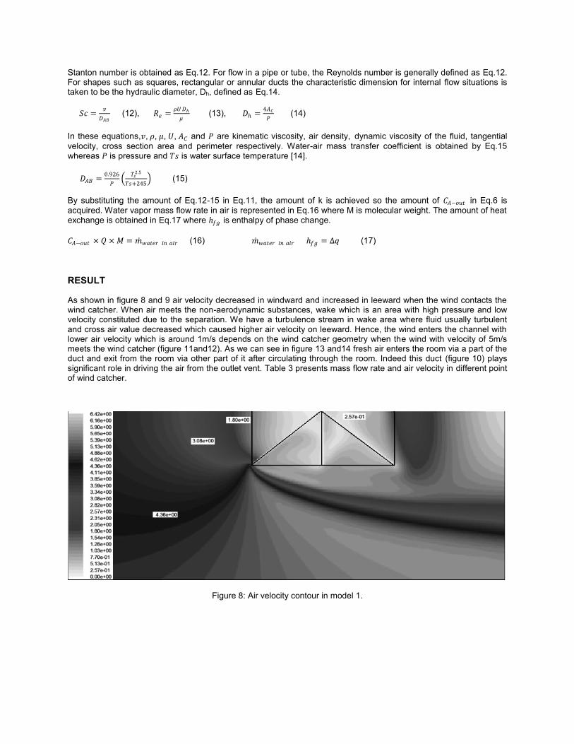
As shown in figure 8 and 9 air velocity decreased in windward and increased in leeward when the wind contacts the wind catcher. When air meets the non-aerodynamic substances, wake which is an area with high pressure and low velocity constituted due to the separation. We have a turbulence stream in wake area where fluid usually turbulent and cross air value decreased which caused higher air velocity on leeward. Hence, the wind enters the channel with lower air velocity which is around 1m/s depends on the wind catcher geometry when the wind with velocity of 5m/s meets the wind catcher (figure 11and12). As we can see in figure 13 and14 fresh air enters the room via a part of the duct and exit from the room via other part of it after circulating through the room. Indeed this duct (figure 10) plays significant role in driving the air from the outlet vent. Table 3 presents mass flow rate and air velocity in different point of wind catcher.
Figure 8: Air velocity contour in model 1.
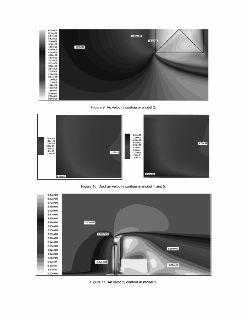
Figure 9: Air velocity contour in model 2.
Figure 10: Duct air velocity contour in model 1 and 2.
Figure 11: Air velocity contour in model 1.
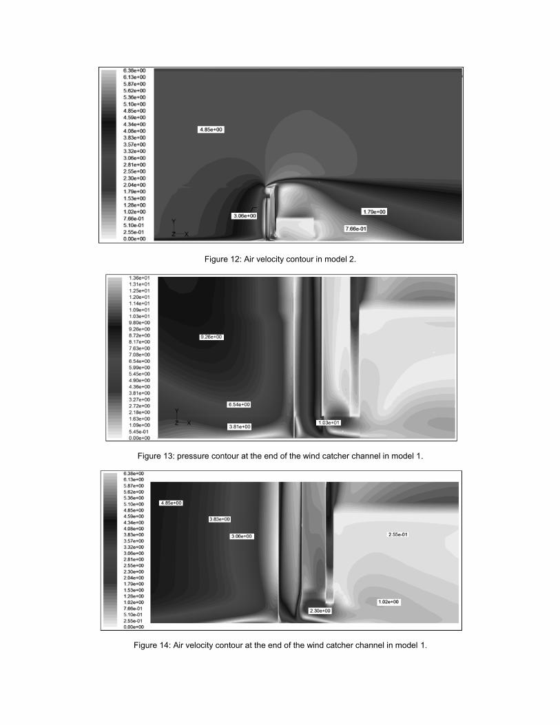
Figure 12: Air velocity contour in model 2.
Figure 13: pressure contour at the end of the wind catcher channel in model 1.
Figure 14: Air velocity contour at the end of the wind catcher channel in model 1.
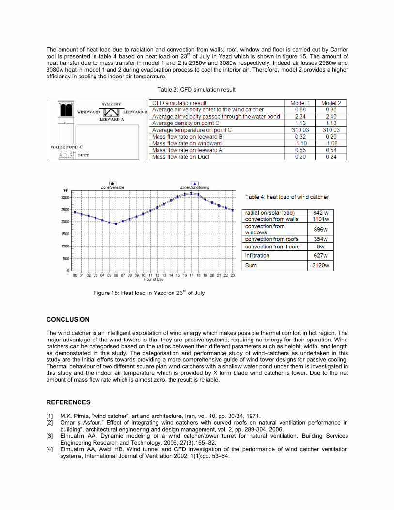
The amount of heat load due to radiation and convection from walls, roof, window and floor is carried out by Carrier tool is presented in table 4 based on heat load on 23
rd of July in Yazd which is shown in figure 15. The amount of
heat transfer due to mass transfer in model 1 and 2 is 2980w and 3080w respectively. Indeed air losses 2980w and 3080w heat in model 1 and 2 during evaporation process to cool the interior air. Therefore, model 2 provides a higher efficiency in cooling the indoor air temperature.
Table 3: CFD simulation result.
Figure 15: Heat load in Yazd on 23rd
of July
CONCLUSION
The wind catcher is an intelligent exploitation of wind energy which makes possible thermal comfort in hot region. The major advantage of the wind towers is that they are passive systems, requiring no energy for their operation. Wind catchers can be categorised based on the ratios between their different parameters such as height, width, and length as demonstrated in this study. The categorisation and performance study of wind-catchers as undertaken in this study are the initial efforts towards providing a more comprehensive guide of wind tower designs for passive cooling. Thermal behaviour of two different square plan wind catchers with a shallow water pond under them is investigated in this study and the indoor air temperature which is provided by X form blade wind catcher is lower. Due to the net amount of mass flow rate which is almost zero, the result is reliable.
REFERENCES
[1] M.K. Pirnia, ―wind catcher‖, art and architecture, Iran, vol. 10, pp. 30-34, 1971. [2] Omar s Asfour,‖ Effect of integrating wind catchers with curved roofs on natural ventilation performance in
building", architectural engineering and design management, vol. 2, pp. 289-304, 2006. [3] Elmualim AA. Dynamic modeling of a wind catcher/tower turret for natural ventilation. Building Services
Engineering Research and Technology. 2006; 27(3):165–82. [4] Elmualim AA, Awbi HB. Wind tunnel and CFD investigation of the performance of wind catcher ventilation
systems, International Journal of Ventilation 2002; 1(1):pp. 53–64.
[5] M.N. Bahadori, M. Mazidi, A.R. Dehghani, Experimental investigation of new designs of Wind Towers, Renewable Energy 33 (2008) 2273–2281.
[6] M.N. Bahadori, An improved design of Wind Towers for natural ventilation and passive cooling, Solar Energy 35 (2) (1985) 119–129.
[7] M.N. Bahadori, Pressure coefficients to evaluate air flow pattern in Wind Towers, in: Proceedings of the International passive and Hybrid cooling conference, American section of the ISES, Miami Beach, Florida, (1981), pp. 206–210.
[8] Yasmina Bouchahm, Ahmed Djouima, The experimentation of improved evaporative cooling wind tower in real office building ,PLEA 2008 – 25th Conference on Passive and Low Energy Architecture, Dublin, 22nd to 24th October.
[9] Liu Lia, C.M. Makb, The assessment of the performance of a wind catcher system using computational fluid dynamics, Building and Environment 42 (2007),pp.1135-1142.
[10] Ali A. Badran, Performance of cool towers under various climates in Jordan, Energy and Building 35 (2003), pp.1031-1035
[11] Roaf, S, ―The Wind catchers of Yazd‖, PhD. Thesis, Oxford Polytechnic, 1988. [12] M. Mahmudi, ―Analyze on Iranian Wind Catcher and its Effect on Natural Ventilation as a solution toward
Sustainable Architecture‖, world Academy of science, Engineering and Technology, pp. 574-579, 2009. [13] Robert E. Treybal, ―Mass transfer operations‖, MacGraw-Hill Book Company, 1980. [14] Thomas K. Sherwood , Robert L. Pigford and Charles R.Wilke, ―Mass transfer‖, MacGraw-Hill Book Company,
1975 .