Embed Size (px)
Citation preview

THE EFFECT Of UNDERWATER EXPLOSIONS
ON SHIP AND SUBMARINE: HULLS ~ .•..
by
J. M. MASSARD
Approved by
J. E. STAllMEYER
and
N. M. NEWMARK
EXPERIMENTAL PROGRAM
FINAL TECHNICAL REPORT
to
BUREAU OF SHIPS
DEPARTMENT OF THE NAVY
Contract NObs 622 50
Index No. NS 724-017
December, i 956
UNIVERSITY OF ILLINOIS
URBANA, ILLINOIS

FL~al Teclli~ical Report on the Experimental Program
TEE EFFECT OF lJNDERWATER EXPLOSIONS ON SHIP AND SUBMlliINE HULLS
Contract NObs 62250 Index No. 724017
by
1;,;1. M. M:!.ssard
Approved by
J. E. stallmeyel'
3.:ld
N. M. Newmark
A Report of a Project in Cooperation irrith
::EE BUREAU OF SHIPS; DEPARrMENT OF THE NA VY
and
TEE UNIVERSITY OF ILLINOIS DKPA..FaMENT OF CIVIL ENGINEERING
li>rDal'..a.) Tll inois :I)ecembel" 1956

THE EFFIDr OF UNDERWATER EL"DLOSIONS
ON SHIP AND SUBMARINE lfu.l.aLS
CONTENrS
:A~30DUCTION .
I..""1troduct ion.
2 - Ac~~owledgment.
3.X:?SRIMEm'AL weRle PRESENrED PREVIOUSLY
:;.
/0
static ~~d Qynamic Tests of Segments of Stiffened Steel Shells.
Static Diametral Loading Tests of Stiffened Steel B."'lells.
S-~atic and D,ynamic External Pressure Tests of Ring Stiffened Cylindrical Shells.
5232~TAL WORK NOJ.: PRESENTED PREVIOUSLY.
7:-~s~~c Vibration Tests of Ring Stiffened ::;--.:... ~ ~d:2.cal Shells.
:::3-:.c.~~2.C ~d Dynamic Tests of Various Steels.
2.. ::D::~:rcx5..uction .
Tes-:'i:ng Apparatus.
_. Ge~eral Discussio~ of ~ield~ 3ehaYio~.
~es:.ll-::;s of M:::te~ial studies.
.?SSULTs OF EXPERIMENTAL PROGRAM
1
1
3
4
4
5
6
9
9
9
10
10
11
l2
15
19
19
23
LIST OF TABLES
Table No.
~. Chemical Compositions of Specimen Steels .
LIST OF FIGURES
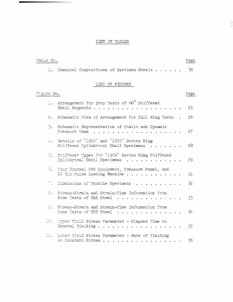
Arrangement fOT Drop Tests of 600 Stiffened Shell Segments . 25
20 Schematic View of Arrangement for Full Ring Tests 26
3. Schematic Representation of Static and Dynamic ?:ressure Tank
l-.....
/0
./ 0
De-tails of :11954:: and ::l955'; Series Ring S~iffe~ed Cylindrical Shell Specimens
St=-fferre:- T:ypes fOT :1195411 Series Ring Stiffened 8y:i~dTical Shell SpecL~ens
::::'8::::- C:~a.---:nel eRO E~uipment, Pressure Panel, and 28 Kip ?clse Loading Machine .
~~~e~siorrs of Tensile SpecL~ens
S~::-ess-Strain and Strain-Time Information from S03e Tests of REA Steel
S~::-ess-StTain and Strain-Time Information from S:=e ?ests of ~!:: Steel
~~?e::- ~ie~d Stress Parameter - Elapsed Time to :~~eral Yielding .
:::"8" ... -er ~ie':'d. S~Tess ?arameter - Rate of Yielding 2.-:, ::;o:::sta.'l.t St:-ess .
27
28
29
31
32
33
35
L"ltroductioD.
TEE Efi',ii'RCT OF UNDERWATER EXPLOSIONS OI~ SB:1P Al~D Sli}3M{lliINE ill Ii J .s
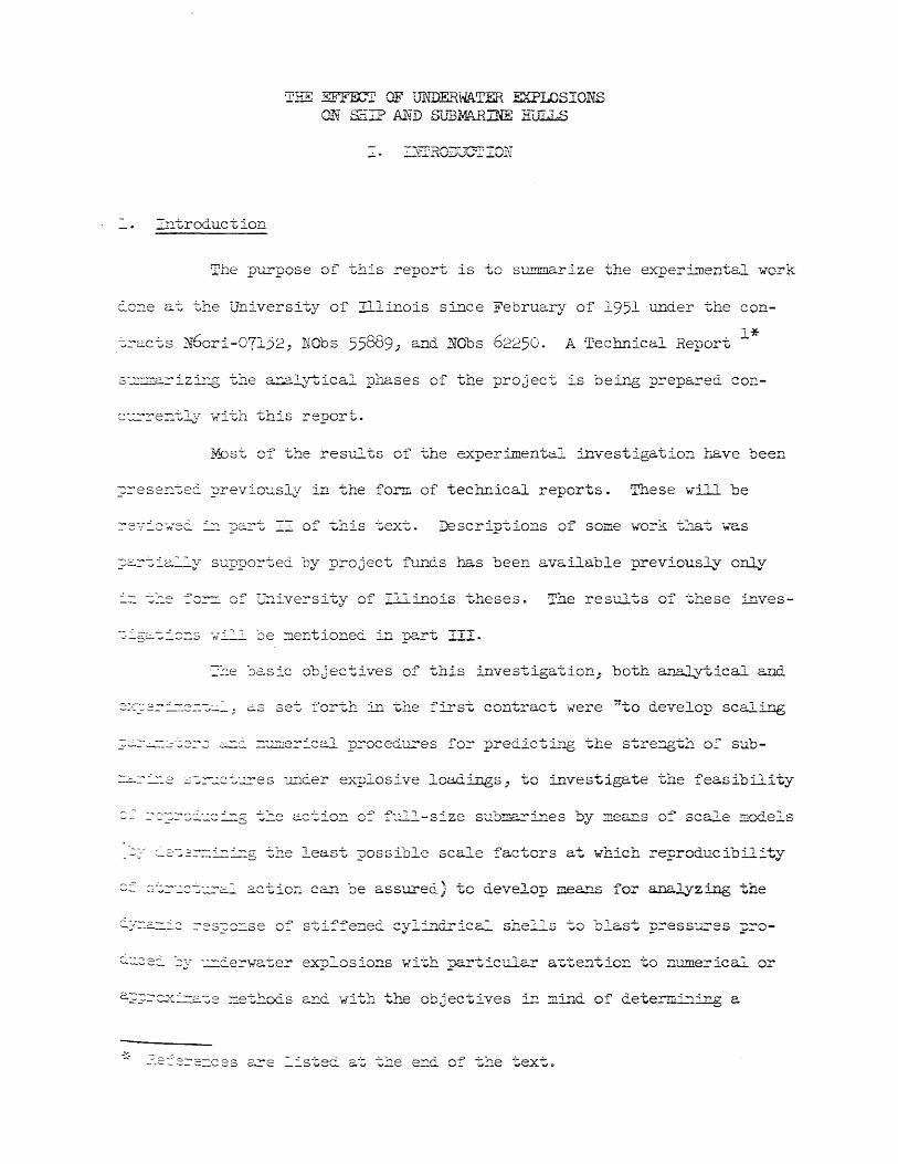
The purpose of this report is to summarize the experimental work
c..8::J.e at the University of lllinois since February of 1951 under the con-
N6ori-07132, NObs 55889; ~~ NObs 62250. A Technical Report 1*
s-..:.:.~::a::-izir~ the a::plytical phases of the project is bei...'1g prepared. co~-
c~re::tly with this report.
Most of the results of the experimental investigation have been
?rese~te~ previously in the form of technical reports. These will be
Descriptions of some work ~na~ w~s
?srti~::y sup~orted by project flh~ds ~zs been available previously only
G::.iveysity 0 7' .. Illinois theseso The resul~s of these :L~ves-
=2e ~csic objectives o? this investigation, both ~~tical and
2Z::;:2=-=--::'::::::::,.:"':'_; CS set forth ill the f-irst contract were ~to develop scaling
~=-~=--:2 s-:.~..:ct~es "Und.er eA.rplosive loadings, to investigate the feasibility
f:.::.ll-size sub'::"!'..p ~-i "'1es by of scale m.odels
-' ~2-:2~i=-=-=g the least possible scale factors at -which reproducibility
S-~~-":'2~~c.=- actio;.] can be assured) to develop means :for a.na.lyzing the
C;::-'.22::" "2y :.::::.:ie:-wc.:te::- explosions with particular attention to numerical or
-:::-

2
~ee~ obtained or which are likely to be developed in the future; and to
ceterm~~e the patterns of force on various types of structures at various
~spects due to the underwater detonation of explosives.~ These were the
stc~ed objec~ives. The expe~imental program at the University of illinois
as l~ developed WdS concerned with the following questions.
:L'1lportant i~ scaljng the behavior
s~b~~L~e pressure hulls?
2. ~~~t is the smallest scale at which reproducibility of ~lJl-
scale behavior car:. be obtained?
rapid loading as compared with those important under slow loading~
~hese were the ~jor ~uestions to be answered by the expe=imentel p=ogram.
:IiJ..:'-i-rg -~he cou:rse of the expeTilnental investigation some related.
These were:
==~e ac~~:::'o~ of Cl shock wave during its impingement upon 2.
2. ~--:D ---- deve::2dence of tl'1e lower na tu..re.l f::-equencies of
=2e slow a~ rapid ~iaxial stress behavior of materials repre-
se~~t:::'ve c~ those fro2 which sub~rlne pTessn~e hulls are currently fabri-
~f ~~e various phases of tbe investigGtion state~ above only the
="2.8'::; s:=.e J ~:::e "je:~.z.v=-or of materials l.L.~e!' slowly and. rapidly appliec. stresses J
- . -~2-:'2.=-_

3
2. Acknowledgment
The work described in this report was performed by the University
of Illinois in cooperation with the Office of Naval Research; and the
Department of the Navy 1 Bureau of' Ships. The work was performed in the
structural Research Laboratory of the Civil Engineering Department which
is under the general direction of N. M. Newmark, Professor of Civil Engi
neering. J. E. sta11meyer, Research Assistant Professor of Civil Engi
neering, bad the responsibility for the general supervision of the entire
program, while supervisors of the experimental program have been W. J.
Hall, and J. M. )l1.ssard, currently Research Assistant Professors of Civil
Engineering.
Other persons who have contributed Significantly to the investi
gation are H. E. stevens then Lt. USN, F. E. Anderson then Capt. USA, E. D.
Patterson, then Capt. USA, W. A. Wails, then Lt. USN, F. L. Howland, L. B.
Smith, and J. W. storm,a.li of whom were then Research Assistants in Civil
Engineer i.ng .
The instrumentation used during the conduct of the investigation
was the direct responsibility of V. J. M:!Donald, Research Assistant Professor
of Civil Engineering, and his assistant, R. J. Craig, Laboratory Technician.

4
II. EXPERIMENTAL WORK PRESENTED PREVIOUSLY
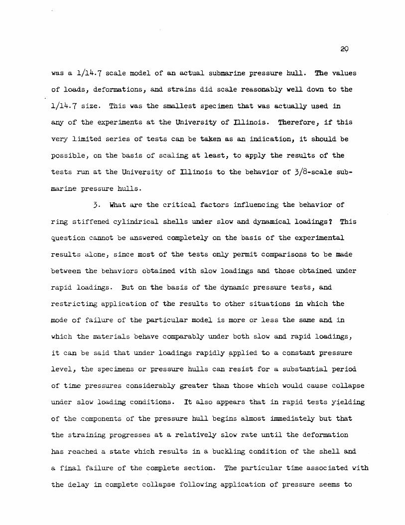
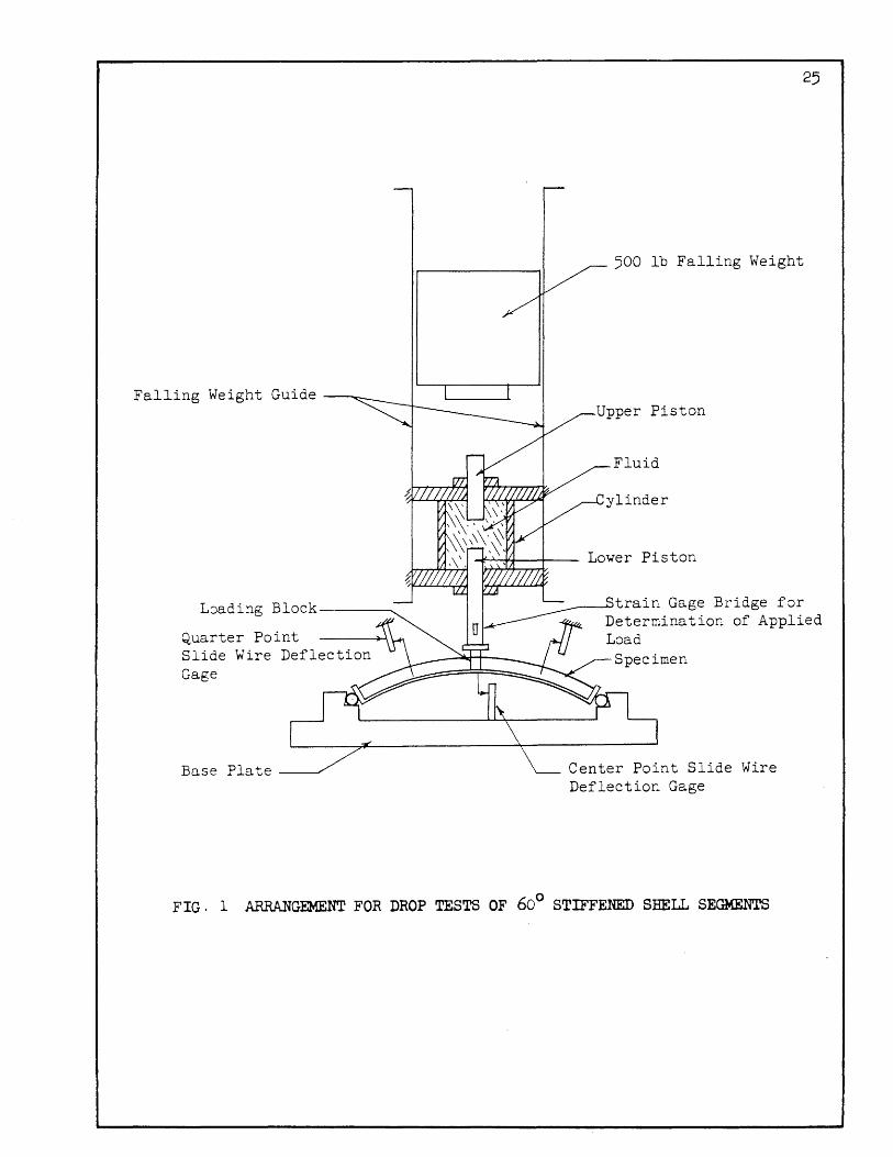
3. static and Dynamic Tests of Segments of Stiffened Steel Shells 4
At the beginning of the experimental program a simple procedure
was sought for determining the relative behavior of ring-stiffened cylin
drical shells under both slow and rapid loadings. This procedure was
desired so that comparisons could be made of the behaviors of various
stiffener sections representative of variations in the parameters con
sidered to be important in the behavior of ring-stiffened cylindrical
shells. The form of specimen finally decided upon was a 60-degree segment
of a full-ring section which was two bays wide with two stiffeners sym
metrically placed about the circumferential center line of the specimen.
The ends of a segment were attached by hinges to a supposedly nonyielding
support. Several of these segments were tested under slow loading and a
companion series was also tested under dynamic loading applied in a drop
testing machine (see Fig. 1). For the first few specimens tested the
loading was applied directly to the top of the stiffeners, but in later
tests it was applied by means of a loading block directly to the crown of
the arch shell between the stiffeners.
The results of the slow tests of the shell segments seemed to
indicate that an H-Section stiffener could be represented fairly well by
a rectangular stiffener having the same area, major moment of inertia,
and area of the composite section as that of the specimen having the H
stiffener. In the drop tests the results are not as clear. Of the speci
mens having bar type stiffeners, those with the same single stiffener area,

5
composite section area, and major moment of inertia. of the composite sec-
tion the same as that of the H-5ectibn behaved most nearly the same as
the H -Section stiffener specimen.
4. Static Diametral Loading Tests of Stiffened Steel Shells5
Another early series of tests was performed on full-ring sections
of ring-stiffened cylindrical shells of three sizes: a 3/8,.,sca.le mcxlel
of a full-size submarine pressure hull, a 1/8 scale, and a 1/14.7 scale
representation of a submarine pressure hull·. These :full-ring sections
were tested under statically applied diametral loading (see Fig. 2). The
purpose of the test series was to determine how well the behavior scaled
down to a size of specimen that was the largest that could be tested in
the dynamic pressure tank then under consideration. The results of these
tests are reported in the Third Technical Report5 for the project. The
summary of this report says that U(l) for the simple loading used the
maximum loads (and the manner of failure) obtained experimentally in the
tvo scale models agreed well with that obtained from the 'prototype' when
2 the comparison was made using the proper power (F ) of the basic scale
factors (F) that had been obtained from consideration of the moments of
inertia of the 'effective sections' obtained by the method of H. Bleich.
However, the results would have been virtually the same had the scale
factors been obtained using the moments of inertia of the 'as measured'
section or those of the 'effective section' computed using the method of
B. ThurlimRnn= (2) For the specimens that seemed to be relatively free
of detrimental residual stress (that is those in which the experimental
behavior was in fair agreement with elementary theory) the elastic regions
of the experimental load-deflection and load-strain curves lay between

6
the corresponding theoretical elastic curves computed from the effective
sections obtained using Bleich's or Thfirlimann's procedure and those ob-
tained assuming that the effective width of the shell beyond the edges of
the inner flanges of the external stiffeners was zero."
5. Static and Dynamic External Pressure Tests of Ring Stiffened Cylindrical
Shells2,3,6
It became apparent during the course of the drop tests of the small
arches that the method had many shortcomings. Therefore, it was decided to
construct a dynamic pressure tank with which controlled long duration ex-
ternal (or internal) pressure loading could be applied rapidly to complete
cylindrical shell models. The dynamic pressure tank, which is described in
2 its early stages of development in the First Technical Report produced
under the contract, is shown schematically in Fig. 3.
After the initial development phases, which were carried on in
the laboratory, indicated that it was necessary to place the tank in a
protective shelter in a rather open area so that the blast resulting from
its operation would not endanger personnel or cause destruction to the sur-
rounding area, a considerable delay was incurred while the funds for con-
structing the testing shelter were obtained and the shelter was constructed.
After the dynamic pressure tank was placed in operation in its new
location, three series of slow and rapid pressure tests of cylindrical shells
were performed. The types of specimens tested in the last two series are de-
scribed in Figs. 4 and 5. Using the dynamic pressure tank it was possible
to apply levels of external pressure to the cylindrical shells in times
as short as 3 or 4 milliseconds. With respect to-the lowest natural

7
frequency of the specimens these were really statical loadings. However,
with res~ct to the behavior of the cylindrical shell model as regards the
properties of the material under rapid loading and also as regards the
buckling behavior of the shell, the loadings were rapid enough that they
could be considered dynamic.
The specimen series, the testing techniques, and the results of
6 the tests are presented in the Fifth Technical Report. The summary of
results given in this report states: "(1) It cannot be said that the
types of failure obtained in the dynamic tests were similar to those
obtained under static testing. The relative stiffener strength had little
effect upon the shell yield failures obtained in most of the static tests
but apparently did influence the time to collapse of the specimens tested
dynamically. (2) The results of these tests indicate that the cylindri-
cal shell specimens withstood for short periods dynamic external pressures
considerably greater than those producing static collapse. (3) In the
cylindrical shell spec imens tested there was little if any delay in the
commencement of shell yielding following the application of dynamic
pressures in excess of those producing yielding under static conditions.
(4) However, in the dynamic tests an appreciable time was required for
the failure process to progress from an initial yielding of the shell to
the point of shell buckling and subsequent failure of the stif'feners. In
the tests of spec :imens baving H-stiffeners the main delay in spec imen col-
lapse apparently was connected with the relatively gradual yielding of the
shell that seems to bear some relation to the rate of yielding phenomena
common to most mild steels. (5) The test results indicate that specimens
which are similar except for the stiffeners and. their spa.cing will behave

&
8
comparably in both static and dynamic testing, providing the effective
clear widths of the shells between the stiffeners are similar) and pro
viding that the major moments of inertia and areas of the stiffeners
alone are similar. n A general comment follows which states that "the
results listed above were obtained in tests of specimens made of mild
steel which had a marked rate of yielding behavior but a delayed yielding
behavior considerably less pronounced than that normal in most mild
steels. Furthermore) the specimens had geometrical proportions and
material properties such that the initial stages of failure were asso
ciated with extensive yielding of the shell. It is not suggested that
these results would be directly applicable to similar structures made of
materials less time sensitive or to those in which the mode of failure
was not equivalent. It

9
ill. EXPERIMENI'AL ~RK Nor PRESmrED PREVIOUSLY -j>
Other work that has been wholly or partially supported by project
.funds but which has not been presented previously in the form of technical
reports is described in this section.
6. Drop Testing Pulse Attenuator
In connection with the drop tests of small shell segment speci-
mens attenuation of the loading pulse was necessary. A device having a
relatively high effective spring constant but a virtual ma.ss as low as
possible was required. The device finally decided upon was a double dis-
placement piston arrangement in which the compressibility of water was
used to achieve the desired spring constant. This unit was interposed
between the falling weight and the crow of the segment being tested. The
calibration of the dynamometer piston of this unit is described in a M. s. . 1
dissertation by F. L. Howland. The test series performed using this
device is described in reference 3.
7. Elastic Vibration Tests of Ring stiffened Cylindrical Shells
One of the sideline investigations mentioned earlier was the
basis for a M. S. dissertation by R. K. Gregory, University of Illinois
1954~ which was entitled, "Determination of the Natural Frequencies of a
8 Ring-stiffened Cylindrical Shell Under External Pressure. ~ Mr. Gregory's
dissertation is being revised concurrently with this report for presenta
tion as a technical report9 under the project.

r i ~ 10 f.
8. Static and Oynamic Tests of Vdrious Steels
a. Introduction •
In the course of the investigation concerned with differences in
the behavior of ring-stiffened cylindrical shells under rapid loading a.s
compared with their behavior under slow loading, it became evident that
information concerning the uniaxial stress behavior of materials under
rapid loading would be of considerable value in understanding the shell
test results. An apparatus with which such testing could be performed
. til was developed as a part of a Ph.D. thesis proJec supported mainly by
University funds. However, approval was given by project monitors to
defray from project funds a part of the cost of preparing and testing spec-
imens.
Following the development of the rapid loading equipment, three
series of tests were performed as a service to the government agencies
requesting them. The results of these tests have been described previously
only in the form of memoranda distributed to the various agencies involved,
13, 14, 15 so pertinent information will be included in this report.
Tvo other thesis investigations were partially supported by this
project. These are described in Reference 10, "A Device to Permit Reversed
Loading in the University of illinois 20 kip Pulse Loading Michine, It by
L. B. Snithj an:i Reference 12, "A .Device for the Rapid Loading of' Small
Beams in the University of illinois 20 Kip Pulse Loading M:lchine," by J. W.
Storm.
A brief description of the material. studies will be given in the
following sections.

11
b. Testing Apparatus
The 20 kip rapid loading machine is a piston device in which the
load output is the result of differential pressure obtained using compressed
nitrogen or helium as the energy source. The load application and release
are achieved using solenoid triggered slide valves to obtain timed pressure
release from the two chambers of the device .. Control of the time required
for load application and release is possible by variation of the orifice
areas. The device is a general purpose unit which permits the application
of a loading pulse to any structural component to which it may be attached.
The applied pulse may begin from a static level ranging from 20 kips tension
to 20 kips compression, undergo a rapid change of plus or minus 20 kips with
the restriction that the prepulse load plus the dynamic change in load can
not exceed the limits of plus or minus 20 kips, and then return rapidly to
zero. The rise and decay times of the loading pulse are controllable from
a minimum of approxima. tely 5 or 6 milliseconds to a maximum of several min
utes. The duration of the peak load may be varied from a few milliseconds
to an indefinite period.
Essentially, the device produces a loading pulse (that is, a pulse
which is nearly independent of specimen response) so that the desired load
ing can be achieved without the need of accurate knowledge of the specimen's
response characteristics. This is true for the particular specimen type
which vas used in most of the studies, since the resulting machine-spec~en
system WdS such that the most rapid loadings of which the machine VdS cap
able without tmpact were virtually static in the mechanical sense of the
word. In use with a specimen which when combined in the machine system
would result in a much lower elastic fundamental frequency, account would

r r t
12
have to be taken of the inertia forces produced a.s a. result of truly
"dynamic" excitation. However, by measuring the resistance of the speci-
men with a dynamometer attached to the end of the specimen opposite that
to which the load was a.pplied, inertia effects would be taken into account,
at least in a nominal way, since these loadings are slow enough that wave
phenomena. are not considered influential. A general view of the rapid
loading apparatus is given in Fig. 6, and the form of tensile specimen
used is shown in Fig. 7 ~
In the early tests cathode ray oscillogra.phs which were virtually
flat in amplitude of response and linear in phase shift to 30 kc were used.
As a result of these tests it was seen that magnetic oscillographic equip-
ment available in the labora.tory would have response cba.ra.cterist:ies quite
adequate for the accurate recording of the test results with the consider-
able advantages of better stability and greater ease of use. This equip-
ment ~s used for the majority of the testing.
c. General Discussion of Yielding Behavior of Mlld and Low Alloy
Steels
The apparatus described in the previous section has been used to
test several steels in slow and rapid uniaxial tension. In general, the
tests were of two types; (1) slow tests at nearly constant rates of nominal
straining, and (2) rapid loading (0.006 sec.) to constant levels of nominal
stress. The chemical compositions of the steels for which results are
included in this report are listed in Table 1.
The nature of the informs.tion obtained from the uniaxial tests
is indicated in Figs. 8 and 9 which show respectively the stress-strain and
strain-time information for a few tests of mild steel (Fig. 8) and high strength

13
steel (Fig. 9). To clarify the writer's interpretation of the results of
the tests represented by such information, a few introductory remarks may
be helpful.
It is a characteristic of mild and low alloy steels that under
a slow relatively constant rate of nominal uni~ial straining at room
temperatures their resistance goes through four rather arbitrary stages:
(1) the elastic range terminating in (2) microstraining followed by the
development of a condition of (3) general yielding (in which the level of
resistance is a function mainly of the rate of straining) which in turn is
terminated by the advent of (4) strain hardening and subsequent fracture.
The four stages in the nominal resistance-deformation characteristics of
these metals are quite evident in the slow straining rate tests, but, of
course, are no less present in tests run under other conditions, such as
slow constant rate of increase in nominal stress.
Of these four stages the middle two, microstraining and general
yielding, are quite time sensitive; the elastic range is almost insensitive
to time; and the range beyond the commencement of strain hardening is only
slightly time sensitive.
The time sensitivity associated with the microstraining phenomonon
" • t1 16 al d d has been termed the delayed Yleld effect . This is best reve e un er
tests involving rapid stressing to a constant stress level such as can be
performed in the University of Illinois 20 kip pulse loading machine. In
the material studies presented in this report the time delay in yielding
is defined arbitrarily as the interval between the time at which the stress
first reaches a value corresponding to the lowest upper yield stress
obtained in slow tests, and the time at which yielding has become general

14
enough that the apparent modulus (nominal stress/nominal strain) has dropped
6 to about 25 .x 10 psi. Delay time so defined has engineering significance
in that it is related at one end to a stress level high enough to result
in yielding under slow loading or deforming conditions, and at the other
end to a parameter involving both stress and strain which has an arbitrary
value indicative of an amount of yielding sufficient to mark the beginning
of general yielding.
The rate of general yielding effect (usually termed somewhat
ambiguously the strain rate effect17) is most evident perhaps in tests per-
formed at various constant rates of nominal strain, but it also will be
apparent, of course, in tests in which nominal stress rather than nominal
strain is the factor most nearly independent of specimen behavior. Such is
the case ::iIl the rapid loading to constant stress level tests. After gen-
eral yielding bas begun (following the delay in yielding if present) the
specimen will deform at a rate which is dependent upon the stress level
being IlE.intained by the pneUJIlE;l.tic loading unit. Since the several tests
are run at different constant stress levels, both delayed yield and rate
of general yielding inf9rmation can be obtained from a single test series.
The sharpness of the transition between the general yielding con-
dition (flat yield region in the constant rate of straining test) and the
region of strain hardening is somewhat more gradual than that between the
other stages. (Of course, the "gradualness" is mainly dependent upon the
time resolution possible with the recording techniques used.) However,
the tests run at the University of Illinois on mild and low alloy steels
indicate that for a particular steel the transition begins at about the
same total strain regardless of the rates involved.

15
In a test to a constant stress level the straining finally ceases
at a total strain which usually agrees well with that corresponding to the
strain obtained at the same nominal stress under slow loading or deforming
conditions.
d. Results of Material Studies
The results of tests performed at the University of D.1.inois (and
elsewhere16) indicate that when subjected to rapid loading to a constant
stress level mild steels (SUCh as REA and SPA) begin to deform almost ilnme-
diately but the straining is limited in extent until sufficient time has
passed and/or microstraining has occurred to result in a condition of gen
eral yielding. This phenomenall-has' been termed delayed yielding by Clark16.
For rapid loadings used at the University of ILlinois in the investigation
of mild steels (rise times of load ranging from 0.005 to 0.5 sec.) the
delayed yield condition can be expressed in terms of the stress at the time
of general yielding and the interval between the time at which the loading
passed a critical level and that at which general yielding began. This
result is illustrated in Fig.IO. It is not believed that such a yield con-
dition which virtually neglects stress history would apply to all types of
loading, particularly those associated with fluctuations in stress.
For mild steels, general yielding once begun continues at a rate
which bears a definite relationship to the instantaneous stress level (see
Fig.ll), until the total strain is about that at which strain hardening
begins under So slowly applied loading. Then the rate- of yielding gradually
decreases until straining virtually ceases at a total deformation which
agrees well with that obtained under slow loading to the same stress level.
(See Fig. 8)

The slow and dynamic properties of the materials representing the
pressure hulls of PAPOOSE and SQUAW (Series :NN and NL respectively) were
somewhat different fram those typical of mild steel. In general there WdS
a delayed yield behavior of sorts. As to the rate of general yielding
behavior, this cannot be indicated very definitely, since, at that time,
overall strain of the gage region was measured only by SR-4 gages, so that
once yielding had progressed to one per cent or so, no further measurement
was possible. But on the basis of the static straining tests which indi-
cated a flat yield region a fairly pronounced rate of general yielding
behavior would be expected.
In the tests of the BY-SO material there was virtually no delayed
yielding nor any very definite rate of general yield behavior as can be seen
from Fig. 9. In general, therefore, this material is not very time sensi-
tive and it is to be expected that compured with mild steel (Fig. 8) there
would be very little increase in resistance of the BY-80 material under
rapid loadings corresponding to those used in the coupon tests.
As was indicated by the theses titles mentioned earlier, a
10 few reversed loading tests were performed on mild steel coupons. A delay
of one or two or so minutes occurred before rapid reversal of stress. Thus,
there is a possibility that some strain ageing occurred. However, the
results did indicate that after havir~ been yielded by a stress pulse
applied in one direction, no (or only a very greatly diminished) delayed
yield behavior was evident upon rapid reversal of stress. The tests were
too limited in extent to signify whether or not the rate of general yield-
ins behavior was affected significantly by a previous history of yielding
under a stress of the opposite sense.

17
Another brief series of material studies that was perfor.med as
a thesis investigation was concerned with slow and rapid loading tests of
12 beams of rect~ section under pure flexure • The loadings were
achieved by an attachment to the 20 kip pulse loading machine with which
third point loadings could be applied to the beams. There were some instru-
mentation difficulties connected with these tests so that the results are
somewhat questionable. Still, it is clear that the resistance obtained at
any particular deformation produced rapidly was substantially greater than
that obtained under the same deformation produced slowly.
An attempt was made to correlate the behavior of these small
beanlli under flexure with the known uniaxial stress properties of the mate-
rial from which the beams were made. In the correlation it was necessary
to assume that the distribution of strains was linear throughout the depth
of the beam section and that the material behaved the same in both tension
and compression. ~king these assumptions and proceeding from the measured
strains and deflections of the beam, resistances in the region of pure
flexure ..... ere computed using the instantaneously measured values of the defor-
mations and the known delayed yielding and rate of yielding behaviors of
the materials from which the beams were made. The resistances obtained by
this cOOlputation were always less than those that were determined from the
loads ~s me~sured by the dynamometers with respect to time. (Of course,
in the elastic region the resistances computed from. the measured deforma.-
tions using the "static" stress-strain relationship agreed quite well with
measured resistance-time information.) The discrepancy in resistance men-
tioned above was on the order of 8 or so per cent for outer fiber strains
in the regions of three times the elastic limit strain to approximately 10

18
times the elastic limit strain. Beyond this, the discrepancy increased l
until in the slow test it was approximately 25 per cent at an outer fiber
stra.in of approximately 100 times the elastic limit stra.in.
In trying to arrive at the reason or reasons for the discrepancy,
there are at least four possibilities to be considered: (1) that there
are possible errors in measurements in either the uniaxial stress tests or
the flexural stress tests, (2) that the material did not behave the same
in tension and compression (on the basis of the coupon tests in both ten-
sion and compression the difference in behavior is insignificant), (3)
that the distribution of strain is not linear through the depth of the sec-
tion, and (4) that the uniaxial stress coupons were not really representa-
tive of the material in the beams. Of these possibilities only (1) and
(3) seem significant.
could be obtained by adjusting the assumed distribution of strain was made
by assuming the distribution to be square or uniform through the depth of
the sectionj this should be the bounding case of maximum resistance cam-
puted on the basis of measured outer fiber strains. The resistances com-
puted using this assumption still were not quite as great as the measured
resistances although they approached them much more qlosely. Therefore
it is reasonable toot there were errors in measurement. The flexural
tests, therefore, cannot be considered as being very conclusive but there
is a definite indication at least that substantial increases in resistances
are obtained in rapid versus slow .flexure, and that a partial explanation
of this increase can be achieved through consideration of the delayed and
rate of yielding behavior of the material from which the specimens were made.

IV. SUMMARY OF RESULTS OF EXPERDElfrAL PROOBAM
9 • Summary of Results
A restatement of the questions which were the basis of the
exper:ilnental investigation follows along with the tla.nsW'ers n obtained.
19
1. What factors are important in scaling the behavior of ring
stiffened cylindrical pressure hullst On the basis of the shell segment
tests results obtained under both slow and rapid loading, and the series
9f cylindrical shells which were tested in the dynamic pressure tank, it
appears that for comparable behaviors H-section stiffeners can be replaced
by bar-type stiffeners baving the same areas and major moments of inertia.
For other behaviors to be comparable, particularly in spec imens which fail
by shell yielding, the effective widths of the shells must be the same
between stiffeners. In the stiffener types which did not have correspond
ing tiXeas and'moments of inertia different behaviors were obtained in both
the slo~ tests and the ~c tests. Therefore, it seems reasonable to
assume that these are major factors affecting the behavior of the ring
stiffened cylindrical shells to both static and dynamical loadings.
2. What is the smallest scale size which will faithfully dupli
cate the behavior of the prototype under both slow and dynamic conditions?
This question cannot be answered positively, since the only experiments
that were performed at the University of Illinois which would apply to this
question were three tests of full-ring pressure hull sections under static
diametral loading. In these particular tests the prototype was a 3/8 scale
model of an actual submarine pressure hull, and the smallest model tested
was a 1/14.7 scale model of an actual submarine pressure hull. The values
of loads, deformations, and. strains did scale reasonably well down to the
1/14.7 size. This was the smallest specimen that was actually used in
any of the experiments at the University of Illinois. Therefore, if this
very limited series of tests can be taken as an iDdication, it should be
possible, on the basis of scaling at least, to app~ the results of the
tes.ts run at the University of Illinois to the behavior of 3/8-scale sub
marine pressure hulls.
3. What are the critical factors influencing the behavior of
ring stiffened cylindrical shells under slow and dynamical loadings? This
question cannot be answered completely on the basis of the experimental
results alone, since most of the tests only permit comparisons to be made
between the behaviors obtained with slow loadings and those obtained under
rapid loadings. But on the basis of the dynamic pressure tests, and
restricting application of the results to other situations in which the
mode of failure of the particular model is more or less the same and in
which the materials behave comparably under both slow and rapid loadings,
it can be said that under loadings rapidly ~pplied to a constant pressure
level, the spec~ens or pressure hulls can resist for a substantial period
of time pressures considerably greater than those which would cause collapse
under slow loading conditions. It also appears that in rapid tests y~elding
of the components of the pressure hull begins almost immediately but that
the straining progresses at a relatively slow rate until the deformation
has reached a state which results in a buckling condition of the shell and
a final failure of the complete section. The particular time associated with
the delay in complete collapse following application of pressure seems to

2l
be relatable to the rate of general yielding behavior of the mild steels
from which were made the shells of the partIcular specimens tested. The
few specimens on which strains were measured as a function of time began
to yield almost immediately, therefore it is not believed that delayed
yielding alone has a very significant effect upon the del~ in actual
collapse of the specimens obtained under the rapid pressure loadings.
It is possible, however, as indicated by the analytical phases
of the project and work by Hofr18, that a major factor contributing to
the time required for collapse to occur following the application of pres
sure is associated with the time required for buckling to occur as a dyna.-
mic process independent of the effect of time sensitive properties of
material. Whether or not the buckling effect or the time required for
buckling to occur can be divorced from the material properties cannot be
stated conclusively at this time. (This could be settled, perhaps, by
running tests of geometrically similar specimens, some made of a material
known to be time sensitive, and others, of a material relatively insensi
tive to time effects in the r~es concerned.) The fact that a delay in
collapse does occur seems to be the really significant thing and indicates
that any theories of failure which are predicated upon collapse following
immediately the initiation of yielding are not applicable to~these tests.
4. )hterial studies. For-the low alloy steels which have been
tested at the University of Illinois (PAPOOSE and SQUAW shell material)
the delayed yielding and rate of yielding behavior is somewhat less pro-
nounced than that which is characteristic of most mild structural steels.
The BY-So material tested has virtually no delayed yield or rate of gen-
eral yieJ.ding behavior, and apparently behaves nearly the same regardless

22
of the rate of loading (at least within the range of load-time relation
ships which were used in the investigation conducted by the University of
illinois).

23
REFERENCES
1. Newmark, N. M., stallmeyer, J. E., and Brooks, J. A., "The Effect of Underwater Explos ions on Ship and SUbmar ine Hulls," Contrac t NOb s 62250, Final Report on Analytical Program, To be presented. as a University of Illinois, Struct. Res. Series Report.
2. Mlssard, J. M., "A Pressure Tank for the Dynamic Testing of Cylindrical Shells," Contract NObs 55889, First Technical Report, University of Illinois struct. Res. Series No. 39 (November 1952).
3. Mlssard, J. M., and Hall, W. J., twA Pressure Tank for the Iqna.mic Testing of Cylindrical Shells, II Fifth Symposium on Underwater Research, Bureau of Ships Report 1953-3 (January 1953).
4. Hall, W. J., and )tl.ssard, J. M., "static and Dynamic Tests of Segments of Stiffened steel Shells," Contract NObs 62250, Second Technical Report, U. of Ill. Struct. Res. Series No. 87 (November 1954), CONFIDENrIAL.
5. M3.ssard, J. M., and Hall, W. J., "The Behavior of stiffened Full Ring Shells Under static Diametral Loading,." Contract NObs 62250, Third Technical Report, U. of Ill. Struct. Res. Series No. 88 (November 1954), CONFIDENl'IAL •
6. }tbssard, J. M., "Static and Iqna.mic External Pressure Tests of Ring Stiffened Cylindrical Sheils," Contract NObs 62250, Fifth Technical Report, U. of Ill. struct. Res. Series No. 111 (August 1955), COHFIDEllrIAL.
7. Howland, F. L., "The Development of an Apparatus .for Applying Pulse Loads to structures," M.S. Thesis, University of IllinoiS (June 1952).
8. Gregory, R. K., tiNa tural Frequency Measurements of a Ring-Stiffened Cylinder, It M. S. Thesis, University o.f Illinois (June 1954).
9. Gregory, R. K., "Natural Frequency ~asurements of a Ring-Stiffened CyliIrlrical Shell, n To be presented as a University of illinois, Struct. Res. Series Report.
10. Smith, L. B., "A Device to Permit Reversed Loading in the University ~ D.linois 20 Kip Pulse Loading M3.chine, ft M.S. TheSis, University of Illinois (February 1955).
11. lthssard, J. M., liThe stress-De.formation Characteristics of Some Mild Steels Subjected to Various Rapid Uniaxial stresstngs," Ph.D. Thesis, University of Illinois (June 1955).

24
12. storm, J. W. J "A ~vice for the Rapid Loading of Snall Beams in the University of Illinois 20 Kip Pulse Loading M3.chine," M.S. Thesis, University of Illinois (September 1955).
13. M:i.ssard, J. M., "Tests of Delayed Yield on M3.terial for the Papoose Program," Contract NObs 62250, ~orandum to UERD (18 September 1954) CONFIDElfrIAL •
14. }wt3.ssard, J. M., "Tests o.f !):layed Yield on M3.terial for SQUAW Program," Contract NObs 62250, M:!morandum to I1l'MB (1 October 1954) CONFIDENTIAL.
15. M:1ssard, J. M., "Rapid Loading Tests of HY-80 Specimens," Contract NObs 62250, Memorandum to Bu Ships Code 423 (13 M3.y 1955) CONFIDENrIAL.
16. Clark, D. S., "The Behavior of ~tals Under Dynamic Loading, U Trans. ASM, Vol. 46 (1954) p. 34.
11. M3.njoine, M. J., and Na.da.i, A., "High Speed Tension Tests at Elevated Temperatures, It Prec. AsrM, Vol. 40 (1940), p. 822.
18. Hoff, N. J., "Buckling and stab ili ty ," J. Roy. Aero. Soc., Vol. 58, No. 1 (January 1954), p. 3.
Falling Weight Guide -~
L~ading Block-------
Quarter Point Slide Wire Deflection Gage
Base Plate ---"'"
25
500 lb Falling Weight
Upper Piston
~~~-+--- Lower Piston
____ --train Gage Bridge for Determination of Applied Load
Center Point Slide Wire Deflection Gage
FIG. 1 ARRANGEJw1ENT FOR DROP TESTS OF 60° STIFFENED SHELL SEGMENTS

D
c=======~~~====~~======~==~======~--Shell
SR-4 Strain Gage
Typical Strain Gage Layout (Sections A,B,C,D)
p L Loading Block
Horizontal Diameter ~ B
FIG. 2 SCHEMATIC VIEW OF ARRANGEMENT FOR FULL RING TESTS
., I
26

Double Diaphragm Release System
Overpressure Mechanisms -~~~~--.--~
40"
I I - --~~ ~.~-~-
Inner Chamber outer C bamber
J.r-}J >, " >, 5} ') 'Y » » » )7 7) }7 77 ); 77 ;; 77 ;; j} ;) ;, ~''/
Section A-A
Double Diaphragm Release System
FIG. 3 SCHEMATIC REPRESENTATION OF THE STATIC AND DYNAMIC PRESSURE TANK
f\)
-.:J

J I _
l4.55 5 at 2.56 = 12.80 1~~' -lit
- fo---
- r-- -
Keel
All dimensions are in inches
Shells Rolled from 14 ga.. (0.072) x 17.9 x 51.52 sheet (Includes allowance for 1/16 gap after rolling.)
Stiffenerss Machined from 18 o. D. "pipe"
Keel: ~4 x 3/4 x 17.9
Assemblyz Metallic arc (reversed polarity) using 3/32 rod. (AWS - ASTM E6ol2 and E6013) (After assembly specimens were trimmed in 1::mld saW' to length given above.)
FIG. 4 DETAIIB OF "1954" AND "1955" SERIES RING STIF'F'ENEO CYLINDRICAL SHELL SP~!MENS f\)
co

r- 0.:524 ---1-±-i 22 n .7.4 a ~.~i.f T
0.064 ~ If''\
• o t'l.{"\
c:--. o
O.081--W 1 ~ If''\ . 0
_1 TYPE I TYPE II TYPE III
-1 0•190!-~~I
0' N If''\ • o
~l TYPE IV
All dim.ensions are in inches
0.120-1
The inside diameter of all stiffeners = 16.40
I r-
T 0"-N If''\ •
0
~
TYPE V
All stiffeners \lere machined from 18 O.D. x linch wll "pipe".
~ !\ ~8. g.t: I
II III
IV
V
--• HC'j N (\j * I I ft...l 0 CD 0 0 o rl +l rl rl "&l +l ~ ~ .. X ~ e-...t asfN f N. ."a . ~!! ~ <4 !l ~~ ;l o orf
4.7 0.23 23.2
4.8 0.23 23.3 4.8 0.14 23.3
10.0 0.23 28.5
6.3 0.15 24.8
*Refers to composite section of stiffener plus portion of shell one bay wide (0.072 x 2.56)
FlU. 5 STIFFENER TYPES FOR tt 1954" SERIES RING STIF'F'EBED CYLINDRICAL SHELL S~IMEBS
(" 1955" Series Specimens ba ve Type I Stiffeners)
.. . ~ ,
Q) CH 0 +lOM erf Ol -+> to<
~~. 00;1 O~
0.51
0.90
0.59 0.83
0.58
ro \0

steel b"'pecimen Desig.· Checked
RBA 2SRBA.28
SPA 2SSPALll
NN NNLll
NL HLTl
NHY NHYL2
TABLE 1 CHEMICAL COMPOSITIONS OF S~IMEN ffrEELS
Chemical Composition (Check Analysis) Description C Mn p S 81 Cu Ni Cr N M:> Ti Va
Rimmed Steel 0.29 0.35 0.021 0.052 0.01 0.014 ~-Hot Rolled 1" q> bar
Semi-killed 0.27 0·51 0.03) 0.036 0.03 0.013 Hot Rolled 1" plate
3/16" Plate 0.18 1.01 0.042 0.039 0.22 0.10 None 0.11 0.017 Representing PAPOOSE
1" Plate 0.16 l.ll 0.027 0.029 0.23 0.33 None 0~13 0.016 Representing ~W
HI80 steel 0.13 0.19 0.006 O.Oll 0.05 None 2.32 1.34 0.010 0.11 Bone 0.05
\..).I
o

FIG. 6 FOUR CHANNEL CRO EQUIPMENT, PRESSURE PANEL, AND 20 KIP PULSE LOADING MACHlliE
(As arranged for testing ten6ion~compre8sion coupons) (L. B. Smith in Photograph)
31

-.-~----~- 8"
1 1/4"1 1 1/4" .f. 2 1/4" --~-t 11/4"-:j t~~: __ r;
7/8 NF-14
Extensometer
3" R.
. Q
I..l\ o l1"\
o
FIG. 7 DIMENSIONS OF TENSILE SP~~
(Except 3/16" Plate Series, NN)
1/8 NF-14
\.}J F\)

~ ~.! , .. - -l-_.;. + -- . - u' ___ . t--. ~ .--i- - -.,.... .. 1- .~-.. - - .-. --r---r--- -~-------r ;-----+-~-~-~- ----- --r·---+-- ----~ -+-1---1-- - ------l--+---+---+--+-+---+~
_ 2, -----t--- .;- - t --h-~+-- - r·- -t- . I--j-+j
-- -- --1--t-i-1.0 10-3 10-2 10-1
Strain (Specimen Deformation), in./in.
lo&~0_-3 __ ~ __ ~~~~~~1~O_-2 ____ ~~~~~~TITO_-_l __ ~ __ ~~~~.,,100 I :; I I : : !II li! II r I i I· ! I I
! ! I! [I I
80~ ____ -++;-+;~+i~I~!4l+-__ ~I __ ~~4-~i' +,~~---+1--+-+-~~-H /
i : I; i I I ~ I i r I ! 1 I ; I· : ; i : I Ii! !
3 I 1
I [ I
I I i i
FIG. 8 TYPICAL STRESS -STRAIN AND STRAIN -TIME RELATIONSHIPS FOR MIID STEEL (MRBA 2, 3, 4, 5, and 10)

103
, 102~~~~·~~~~~~~···~-~--E~~~~~~_~·~_~~~~·~_~r~. __ ~ .. ~.~.l.~ .. I=._t-lif+j·-E·~~~~=1·~~.~.~-jr-~.~~~El~~4 I ~'-----+---4--+-+-~~++------+---+--4--+~~~~~=-------~--+-~-+~~~ I 1
'1 '---~4-~~~------+---~=-~~-~~-'.-+~+'-~~----+---~~~~~~ -~ --.... ---I I ..:t. .j_-.... -+~-:::-..--........... ~-=----.--~. r--- - - - --~f---+--+--+-+-+--
2 L 101 ..:-,.~ ~ 10 I . -1-. .---. r-
I .-'---. --~-.- • lLC[l ·l-~ 2.e-:'c~ '- - . r- -.
-+----.. r-.. ·r-.---'/t- - .-.-+-.~----.--- .... - .. - .. ~ '·-1 .--f-- -r· ~~~ ----·r-'r-- --;{ofio~2"-+--+-+- +-+-+---._.--- +--f---+'-+--+-i-+-i
~ -.----.-1- .... -+ .. -'-- .-.- +-r-f-- .. _-t--fl.-+---t--+-+-+-+--+---.-~-.. --+-
o 100 ~ ... i . i . I . I I I : o -. -$ -.:i:.--+. ,..- ·f . " -. ... t--+- .- --1-.
Cf.l -- .. ---1" I --t.- .1 --f-.
, ,=-:-:-:.---=L--~~=r~ ~-t~. --:-.:--1----1 ---if-~_ - -1== ! _le---
L-: i -. ---h -r1--j-1 -,--- -~--___+_I--+---+---+--+--+-+-+-i
~ 10 r-' -t- - . ..... j. •.. --. f-- - f-I·---f~ -+>-- .--~ .. - ..... t-. --... .s ,..... -. --- t· . -. -.. ~ . -- .. -~ tl·- ----t-:=!_ --r+-- ·---r·- r·_·· -.-r-. .-r- - r - -t - I :+---+--+--+--+-~-+-+----
\-4 o , i--t-.J I 1 1
------+--' .- i===f II, 1J~ -f-·-+f-+---+---+-IJ' ~ 10-
2 ----~---n1 / V 7-- ,-r-r-e------- I
:=-. ~·-::±:-7~· --::~
r---' .-r - -...- . ...:."_ -------I-----+--+-+-+.-+-+-+-+----.4-----+---+.....---1f--t--+--+-+-f ~ I -t- ·--- ... -+-.. l· ..... l-+-i--·~t ~.---+---+-- --f---~-,..-+-~++------~--~-_+_~_+_~~
_:1\ i I IiI 10 10-3 10-2 10-1
Strain (Specimen Deformation), in./in. 10-2 10~1
I I , . ~ I I I -----k ~~ 10' ....
... ~ I-~ • ~, I I : I ~ ..
! 1 1 , , I I _ ......
. .. I Ii£-~~ ~ l~.,.. .... - '\
:~t-r- .. ~ , \ 1 .~
, U~
I·
i I \ I
i I I
I ,
I' i iii i i I I
I iii I
! : I : I ! I I 'I : , ' I
or-! 80 co
.!14 ... ---.
4) u ,
60 to or-! co QJ p:::;.
/ : i ! ;
I I I i i
/ I
! ! t
I
! I
~
] 40 u d> P.
tf) -- : !
I I Ul
~ I 1 j
i I I I
i I i
co ~ 20 +'
Cf.l
I
I ,
I o FIG. 9 TYPICAL STRESS-STRAIN ArID STRAm-TIME RELATIONSHIPS FOR HY80 MATERIAL
(NHYL 12, 18, 19, 2C, and 22)

I II "I I I 1111111 I I Test Series C1 *,ksl
uy
0·5 ----- -Rimmed Steel, Longitudinal Semi-killed Steel, Longitudinal Semi-killed Steel, Transverse Papoose Steel, Longitudinal Papoose Steel, Transvers.e
0.4 . Squaw Steel, Longitudinal Squaw Steel, Transverse
• DY80 Steel, Longitudinal ~ nBG Steel, Trans verse
b ........... ........ • ~
b O.3r---~~~~-+~-+~~~--~~~
~ t) ~
•
II
-$-Il
0.1 ~
o 10.-3
-e-
10-2
-8--$-10-1
MRBA SPAL SPAT NNL NNr NLL HLT NHYL HIfiT
lOU
o <l> -a-II d \I t> ij] -e
48.1 31·5
------ 38.2 5.5·7 53·1 51·9 56.0
----.....;.-. 80.2 ------ 84.1
'c:.::c:J
lOoL
t I: Elapsed Time to General Ile1ding (tJ / ~ • 25 x 106
ps i) in seconds I (t -0 when a • auy*) y y ~
FID. '10 UPPER YIELD BrRESS PARAMm'ER - ELAPSED TINE TO GDERAL YIELDlB}
-
-
\.J4 \J1

Test Series
0·5
0.4
lImA
SPAL
SPAT
.~ I ; I
tJ i I I ........... ,.....,. • ~ 0·3 I I
b I
1 i ~ I
b '-"
o ~
-e-
0ly *,k.si
37·5 32·7
--- -- 35·0
I I
I ., ;,)
• ~ 0.2
Y 'I
i i I I :
/!
I ! I
I
-e- ' ~
/-&! ,........~ I i
I ' . 0.1 . I "':-1 I
r ~:
tr' I~I IIA'II o .JI:.~...,..._~~, ~i '~~-3
i I I
! I
10-2 10-1
Rate of General Yielding, in./in./sec.
l'lG. 11 toWER YIELD fJrRESS PAlWE.rER - RATE OF YIELDlBG AT CC»i8l'AJfr fIrRESS
'\
100
\..N CJ\

DISTRIBUTION LIST
for
Technical and Final Reports Issued Under Contract NObs 62250, Index No. NS 724-017
I. Administrative, Reference and Liaison Activities
Chief of Naval Research Department of the Navy Washington 25, D. C. Attn: Code 438
Code 432 Code 466 (via Code 108)
Director, Naval Research Lab. Washington 25, D. C. Attn: Tech. Info. Officer
Technical Library Mechanics Division
Commanding Officer Office of Naval Research Branch Office 495 Summer Street Boston 10, Massachusetts
Commanding Officer Office of Naval Research Branch Office 346 Broadw-ay
(2) (1) (1)
(2)
Commanding Officer Office of Naval Research Branch Office 1000 Geary Street San Francisco 9, California
Commanding Officer ~ffice of Naval Research Branch Office 1030 Green Street Pasadena, California
Officer in Charge Office of Naval Research Branch Office, London Navy No. 100 FPO, New York, New York
Commanding Officer Office of Naval Research The John Crerar Library Bldg. Tenth Floor, 86 E. Randolph St.
(1)
(1)
New York 13, New York (1) Chicago 1, Illinois (1)
Library of Congress Washington 25, D. C. Attn: Navy Research Section (2)
II. Department of Defense and Other Interested Government Activities
(a) General
Research and Development Board Department of Defense Pentagon Building Washington 25, D. C. Attn: Library (Code 3D-1075) (1)
Armed Forces Special Weapons Pro. P. O. Box 2610' Washington, D. C. Attn: Col. D. L. Lay {2)

Distribution List
(b) Army
Chief of Staff Department of the Army Research and Development Division Washington 25, D. C. Attn: Chief of Res. and Dev. (1)
Engineering Research and Development Laboratory Fort Belvoir, Virginia Attn: Structures Branch (1)
Office of the Chief of Engineers Asst. Chief for Military Operations Department of the Army Bldg. T-7, Gravelly Point Washington 25, D. C. Attn: Structures Development
Branch (W. F. Woollard) (1)
The Commanding General Sandia Base, P. o. Box 5100 Albu~uer~ue, New Mexico Attn: Col. Canterbury (1)
Office of the Chief of Ordnance Office of Ordnance Research Department of the Army The Pentagon Annex No. 2 Washington 25, D. C. Attn: ORDTB-PS (1)
(c) Navy
Chief of Naval Operations Department of the Navy Washington 25, D. C. Attn: OP-31 (1)
-- ~/"~ I~\ U~-)O) \~)
Director David Taylor Model Basin Department of Navy Washington 7, D. C. Attn: Code 720, Structures Div. (1)
Code 740, Hi-8peed Dynamics Div. (1)
ii
Office of the Chief of Engineers Assistant Chief for Public Works Department of the Army Bldg. T -7, Gravelly Point Washington 25, D. c. (1) Attn: Struc. Branch, R. L. Bloor
Office of the Chief of Engineers Asst. Chief for Military Const. Department of the Army Bldg. T-3., Gravelly Point Washington 25, D. C. Attn: Structures Branch
(M. F. Cary) (1) Protective Construction Branch {M. D. Kirkpatrick) (1)
U. S. Army Waterways Exp. Station P. O. Box 631 Halls Ferry Road. Vicksburg, Mississippi Attn: . Col. C. H. Dunn (1)
Operations Research Officer Department of the Army Ft. Lesley J. McNair Washington 25, D. C. Attn: Howard Brackney
Ballistics Research Laboratory Aberdeen Proving Ground Aberdeen, Maryland
(1)
Attn: Dr. C. W. Lampson (1)
Chief of the Bureau of Ships Department of the Navy Washington 25, D. C. Attn: Code 310
Code 423 Code 442 Code 421 Code 312 Code 376 Code 537
Commander Portsmouth Naval Shipyard Portsmouth, N. H. Attn- np~ion niv;~;nn

Distribution List
Commanding Officer Underwater Explosions Research Div. Code 270 Norfolk Naval Shipyard Portsmouth, Virginia (2)
Naval Ordnance Laboratory Whi te oak, Maryland RFD 1, Silver Spring, Maryland Attn: Mechanics Division (1)
Explosive Division (1) Mech. EvalWttion Div. (1)
Naval Ordnance Test Station Underwater Ordnance Division Pasadena, California Attn: structures Division (1)
Superintendent U. S. Naval Post Graduate School Monterey, California (1)
Mr. F. X. Finnigan ONR Local Representative 1209 West Illinois Street Urbana, Illinois (1)
Commanding Officer U. S. Naval Training School Massachusetts Institute of Technology Cambridge, Massachusetts (1)
(d) Air Forces
Commanding General U. S. Air Force The Pentagon Washington 25, D. C. Attn: Res. and Develop. Div.
Commander Air Force Special Weapons Center Attn: SWRS,r Mr. Eric Wang
(1)
Kirtland Air Force Base, New Mexico (1)
(e) Other Government Agencies
U. S. Atomic Energy Commission Division of Research Washington, D. C. (1)
iii
Director, Materials Laboratory New York Naval Shipyard Brooklyn 1, New York (1)
Chief of Bureau of Ordnance DejlaJrt,ment of the Navy Washington 25, D. C. Attn: Ad-3, Technical Library (~)
Rec, P. H. Girouard (1)
Commander U.S. Naval Ordnance Test Station Inyokern, California Post Office--China Lake, Calif.
. Attn: Scientific Officer (1)
Chief of Bureau of Aeronautics Department of the Navy Washington 25, D. C. Attn: TD-41, Technical. Library (1)
Officer in Charge Naval Civil Eng. Res. and Eval. Lab. Naval. Station Port Hueneme, California (1)
Superintendent U. S. Naval Academy (Dept. of Marine Engineering) Annapolis, Maryland (1)
Deputy Chief of Staff, Operations Air Targets Division Headquarters, U. S. Air Forces Washington 25, D. C. Attn: AFOIN-3J3 (1)
Director, Nat'l Bureau of Standards Washington, D. C. Attn: Dr. W. H. Ramberg (1)

Distribution List
. Dr. J. H. Hollomon General Electric Research Labs. 1 River Road. Schenectady, New York
(unclassified only) (1)
Dr. W. H. Hoppman Dept. of Applied Mechanics Johns Hopkins University BaJ. timore'·, Maryland
Professor L. S. Jacobsen Dept. of Mechanical Engineering Stanford University
(1)
Stanford, California (1)
Professor J. Kempner Dept. of Aero. Eng. and Applied Mech. Polyte~hnic Inst. of Brooklyn 85 Livingston Street Brooklyn 1, New York (1)
Professor George Lee Dept. of Mechanics Rens~alaer Polyteehnic Institute Troy, New York
(unclassified only) (1)
Professor Paul Lieber Dept. of Aeronautical Engineering Renssalaer Polytechnic Institute Troy, New York (1)
Professor R. D. Mlndlin Dapt. of Civil Engineering Columbia University New York, New York (1)
Professor Glen Murphy, Head Dept. of Aeronautical Engineering Iowa State College .Ames, Iowa
(unclassified only) (1)
Professor N. M. Newmark Dept. of Civil Engineering University of Illinois Urbana, Illinois (2)
Professor Jesse Ormondroyd University of Michigan Ann Arbor, Michigan
. (unclassified only)
Dr. W. R. Osgood
v
(1)
Department of Mechanics Rensselaer Polytechnic Institute Trqy, New York
(unclassified only) (1)
Dr. A. Phillips School of Engineering Stanford University Stanford, California
(unclassified only)
Dr. W. Prager, Chairman Grad. Div. of Applied Math. Brown University Providence 12, Rhode Island
Professor E. Reissner Dept. of Mathematics Mass. Inst. of Technology Cambridge 39, Mass.
(unclassified only)
Professor M. G. Salvadori Dept. of Civil Engineering Columbia University Broadway at ll7th Street New York 27, New York
(unclassified only)
Webb Institute Glen Cove Long Island, New York
Professor D. S. Clark
(1)
(1)
(1)
(1)
Dept. of Mechanical Engineering California Institute of Technology Pasadena, California
(unclassified only)