Embed Size (px)
Citation preview
The effect of the front-to-rear wheel torque distribution on vehicle handling: an experimental assessment
BUCCHI, Francesco, LENZO, Basilio <http://orcid.org/0000-0002-8520-7953>, FRENDO, Francesco, DE NIJS, Wouter and SORNIOTTI, Also
Available from Sheffield Hallam University Research Archive (SHURA) at:
http://shura.shu.ac.uk/15981/
This document is the author deposited version. You are advised to consult the publisher's version if you wish to cite from it.
Published version
BUCCHI, Francesco, LENZO, Basilio, FRENDO, Francesco, DE NIJS, Wouter and SORNIOTTI, Also (2017). The effect of the front-to-rear wheel torque distribution on vehicle handling: an experimental assessment. In: IAVSD 2017 : 25th International Symposium on Dynamics of Vehicles on Roads and Tracks, Rockhampton, Queensland, 14-18 August 2017. (In Press)
Copyright and re-use policy
See http://shura.shu.ac.uk/information.html
Sheffield Hallam University Research Archivehttp://shura.shu.ac.uk
1 INTRODUCTION
The handling characteristics of a vehicle are key factors for safety and performance. Since the 1970s vehicle cornering response has been studied through simulation models. The first studies were based on linearized single-track vehicle models for steady-state cornering conditions, un-der the hypothesis of small slip angles and steering angles, and introduced the concepts of han-dling diagram and understeer coefficient (Pacejka 1973). These analyses were complemented by the characterization of the transient vehicle response through the single-track model, and by the progressive introduction of more advanced simulators, including consideration of non-linear tire force characteristics and suspension elasto-kinematics.
Later on the science of vehicle dynamics focused on direct yaw moment control (DYC) (Shibahata 1993, van Zanten 2000), i.e., a technique aimed at enhancing vehicle handling by controlling the brake or drive torques of each wheel. This allows generating a yaw moment through the difference in longitudinal tire forces on the left- and right-hand sides of the vehicle. Initially DYC was applied to stability control in extreme transient conditions, through the actua-tion of the friction brakes during emergency maneuvers. More recently, several authors (for ex-ample, De Novellis et al. 2014, De Novellis et al. 2015, Lenzo et al. 2016, Lenzo et al., in press) proposed continuously active DYC algorithms, with the specific purpose of designing the vehi-cle handling characteristic according to multiple driving modes selectable by the user. These advanced controllers were experimentally assessed on electric vehicles with multiple motors.
The effect of the front-to-rear wheel torque distribution on vehicle handling: an experimental assessment
F. Bucchi Dipartimento di Ingegneria Civile e Industriale, Università di Pisa, Pisa, Italy
B. Lenzo Department of Engineering and Mathematics, Sheffield Hallam University, Sheffield, UK
F. Frendo Dipartimento di Ingegneria Civile e Industriale, Università di Pisa, Pisa, Italy
W. De Nijs Flanders MAKE, Lommel, Belgium
A. Sorniotti Centre for Automotive Engineering, University of Surrey, Guildford, UK
ABSTRACT: The front-to-rear wheel torque distribution influences vehicle handling and, ulti-mately, affects key factors such as vehicle safety and performance. At a glance, as part of the available tire-road friction is used for traction on the driven axle, a Front-Wheel-Drive (FWD) vehicle would be expected to be more understeering than a Rear-Wheel-Drive (RWD) vehicle with equivalent characteristics. However, in specific conditions such effect may be counter-balanced, or even reversed, by the yaw moment caused by the lateral contribution, in the vehicle reference system, of the traction forces at the front wheels. This paper discusses the experi-mental assessment of the phenomenon in steady-state cornering, for a fully electric vehicle with multiple motors, allowing different front-to-rear wheel torque distributions. The results confirm that the yaw moment effect of the front traction forces is significant, especially at low vehicle speeds and high lateral accelerations. In particular, in the case study maneuvers, the RWD con-figuration of the vehicle resulted more understeering than the FWD one at the speed of 30 km/h.
Also in more conventional vehicle layouts, depending on the differential typology and opera-ting condition, the longitudinal tire forces affect the cornering response, as discussed in (Frendo et al. 2006, Frendo et al. 2007). In particular, (Bucchi & Frendo 2016) proposed a detailed yaw moment analysis, assessing the influence of the individual yaw moment contributions, e.g., those related to the lateral tire forces and longitudinal tire forces, on the level of vehicle under-steer and oversteer. Interestingly, they found significant differences among the cornering re-sponses of the Front-Wheel-Drive, Rear-Wheel-Drive and All-Wheel-Drive architectures (re-spectively indicated as FWD, RWD and AWD in the remainder) implemented on the same vehicle plant. In particular, with reference to a skid pad maneuver, the RWD vehicle resulted more understeering than the FWD and AWD configurations, which is the opposite of the com-mon belief (Osborn & Shim 2006). The reduced level of understeer of the FWD configuration is caused by the destabilizing yaw moment of the lateral component (in the vehicle reference sys-tem) of the front longitudinal tire forces in traction. These findings were only supported by multibody model simulations, while an experimental proof is missing in the literature, to the knowledge of the authors.
The contribution of this paper is the experimental validation of the analysis proposed in (Bucchi & Frendo 2016). Several ramp steer maneuvers were performed with a fully electric vehicle demonstrator with four on-board motors, allowing the controlled implementation of any front-to-rear or left-to-right wheel torque distribution. The effects of the FWD, RWD and AWD layouts on the experimentally measured handling diagrams at constant speed are presented and discussed.
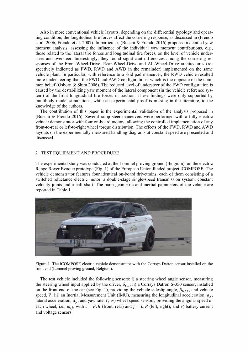
2 TEST EQUIPMENT AND PROCEDURE The experimental study was conducted at the Lommel proving ground (Belgium), on the electric Range Rover Evoque prototype (Fig. 1) of the European Union funded project iCOMPOSE. The vehicle demonstrator features four identical on-board drivetrains, each of them consisting of a switched reluctance electric motor, a double-stage single-speed transmission system, constant velocity joints and a half-shaft. The main geometric and inertial parameters of the vehicle are reported in Table 1.
Figure 1. The iCOMPOSE electric vehicle demonstrator with the Corrsys Datron sensor installed on the front end (Lommel proving ground, Belgium).
The test vehicle included the following sensors: i) a steering wheel angle sensor, measuring the steering wheel input applied by the driver, ; ii) a Corrsys Datron S-350 sensor, installed on the front end of the car (see Fig. 1), providing the vehicle sideslip angle, , and vehicle speed, ; iii) an Inertial Measurement Unit (IMU), measuring the longitudinal acceleration, , lateral acceleration, , and yaw rate, ; iv) wheel speed sensors, providing the angular speed of each wheel, i.e., , with , (front, rear) and , (left, right); and v) battery current and voltage sensors.
The tests consisted of ramp steer maneuvers executed at 30 km/h, 60 km/h and 80 km/h. The FWD layout, RWD layout and AWD layout with 50:50 front-to-rear wheel torque distribution were emulated through the appropriate control of the electric drivetrains. In particular, the torque distributions were set through the dSPACE AutoBox system installed on the vehicle. In all cases the wheel torques were evenly distributed among the left- and right-hand side wheels. The desired vehicle speed was maintained throughout the maneuvers by means of a PI (Propor-tional Integral) speed tracking feedback controller, comparing the reference speed with the actu-al speed. The tests were executed according to the following procedure: i) the vehicle was ac-celerated from standstill to the reference speed in straight line, using the PI speed tracking controller; ii) when the reference speed was reached, a ramp in steering wheel angle was applied by the driver with approximately constant rate (~2 deg/s). The low value of steering wheel rate made the vehicle operate close to its steady-state condition; iii) the test was considered to be completed when the vehicle yaw rate reached its saturation level, i.e., when the yaw acceleration dropped to zero. Steps i)-iii) were repeated for the three vehicle speeds and three wheel torque distributions.
Table 1. Main vehicle parameters. _______________________________________________________________
Symbol Name and unit Value _______________________________________________________________
Mass (kg) 2290 Front semi-wheelbase (m) 1.365
Wheelbase (m) 2.665 Transmission ratio (-) 10.56
Wheel radius (m) 0.364 Track width (m) 1.616
_______________________________________________________________
3 RESULTS AND DISCUSSION
3.1 Data post processing
The relevant vehicle dynamics variables were obtained from the measurements and the geome-try of the vehicle, by using a simple single-track model (Genta 1997) and the adapted ISO sign convention (Pacejka 2006). Each measured signal was adequately filtered to reduce the effect of measurement noise.
The value of sideslip angle at the center of mass of the vehicle, (this location is the most commonly used in the literature), was obtained by combining with and , which is the longitudinal component of the velocity of the vehicle center of mass (Genta 1997, Guiggiani 2014): tan tan (1) where is the longitudinal distance between the front axle of the vehicle and the Datron sensor.
As the steering ratio of the car is not constant, a non-linear map was used to obtain the stee-ring angles of the left and right wheels (respectively, and ) as functions of . Starting from the average of and , i.e. defining the steering angle , the single-track model was adopted to estimate the dynamic steering angle, , i.e., the difference between the slip angles of the front and rear axles.
3.2 Handling diagram and vehicle response analysis
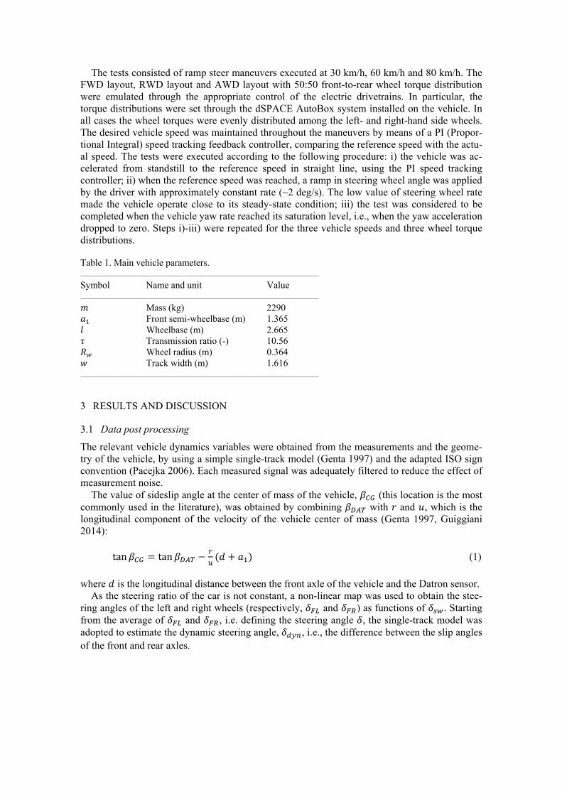
Figure 2 reports the dynamic steering wheel angle as a function of lateral acceleration for the considered vehicle speeds. In general, the resulting characteristics are very similar for the three vehicle configurations at 60 km/h and 80 km/h.
A perceivable difference in the handling behavior of the three vehicle configurations is ob-served at 30 km/h and high , with the RWD configuration being more understeering than the FWD one. This result is caused by the front longitudinal tire forces, provoking a destabilizing yaw moment because of the steering angle at the front wheels. To quantify this effect, the front longitudinal tire forces and are estimated from the front motor torque demands,
and , the efficiency of the drivetrain, , the gear ratio, , and the wheel radius, , which is assumed constant. The yaw moment contribution associated with and is: sin sin (2)
As a consequence, increases with , and . This justifies the variation of the han-dling diagram at low speed and high lateral acceleration. In fact, at low the same lateral acce-leration is achieved with a higher value of , which implies a more significant effect of . Al-so, the longitudinal traction force increases with , because of the losses caused by the lateral tire slip.
Figure 2. Dynamic steering angle as a function of lateral acceleration.
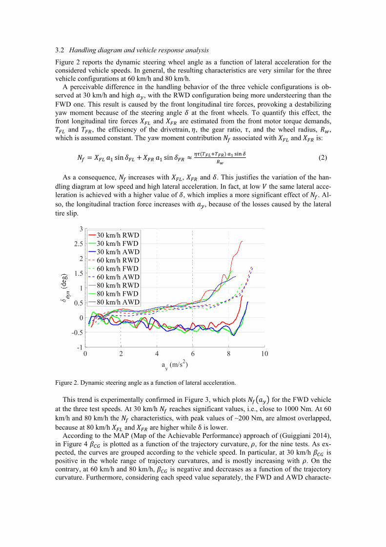
This trend is experimentally confirmed in Figure 3, which plots for the FWD vehicle
at the three test speeds. At 30 km/h reaches significant values, i.e., close to 1000 Nm. At 60 km/h and 80 km/h the characteristics, with peak values of ~200 Nm, are almost overlapped, because at 80 km/h and are higher while δ is lower.
According to the MAP (Map of the Achievable Performance) approach of (Guiggiani 2014), in Figure 4 is plotted as a function of the trajectory curvature, , for the nine tests. As ex-pected, the curves are grouped according to the vehicle speed. In particular, at 30 km/h is positive in the whole range of trajectory curvatures, and is mostly increasing with . On the contrary, at 60 km/h and 80 km/h, is negative and decreases as a function of the trajectory curvature. Furthermore, considering each speed value separately, the FWD and AWD characte-
0 2 4 6 8 10ay (m/s2)
-1
-0.5
0
0.5
1
1.5
2
2.5
330 km/h RWD30 km/h FWD30 km/h AWD60 km/h RWD60 km/h FWD60 km/h AWD80 km/h RWD80 km/h FWD80 km/h AWD
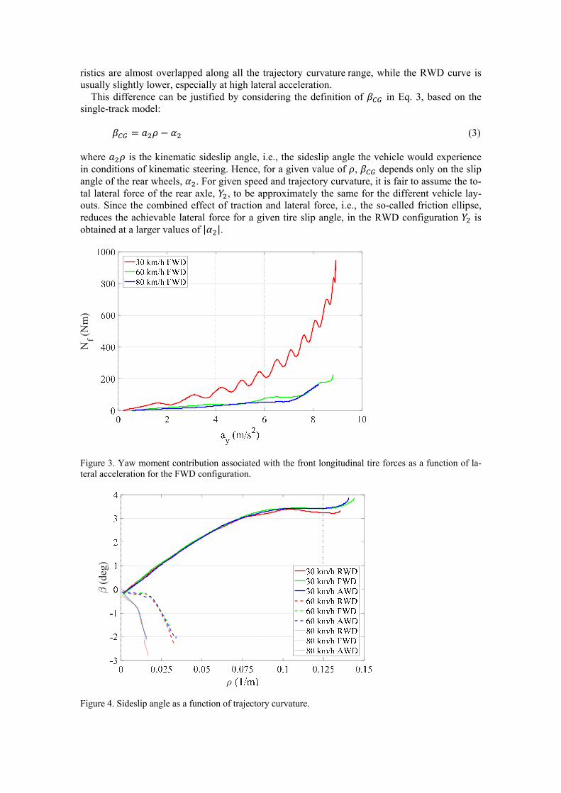
ristics are almost overlapped along all the trajectory curvaturerange, while the RWD curve is usually slightly lower, especially at high lateral acceleration.
This difference can be justified by considering the definition of in Eq. 3, based on the single-track model:
(3) where is the kinematic sideslip angle, i.e., the sideslip angle the vehicle would experience in conditions of kinematic steering. Hence, for a given value of , depends only on the slip angle of the rear wheels, . For given speed and trajectory curvature, it is fair to assume the to-tal lateral force of the rear axle, , to be approximately the same for the different vehicle lay-outs. Since the combined effect of traction and lateral force, i.e., the so-called friction ellipse, reduces the achievable lateral force for a given tire slip angle, in the RWD configuration is obtained at a larger values of | |.
Figure 3. Yaw moment contribution associated with the front longitudinal tire forces as a function of la-teral acceleration for the FWD configuration.
Figure 4. Sideslip angle as a function of trajectory curvature.
(deg
)
Nf(N
m)
4 CONCLUSION
The experimental study of this paper highlighted the effect of the front-to-rear wheel torque dis-tribution on the cornering behavior of an electric vehicle with multiple motors. In particular, the main factor is the yaw moment generated by the lateral component of the traction forces. This contribution is an increasing function of the steering angle. For the case study vehicle demon-strator, at the speed of 30 km/h and large values of lateral acceleration the RWD configuration resulted more understeering than the FWD one. Such effect is independent of the presence of a direct yaw moment controller.
Future studies will analyze the effect of all the individual yaw moment contributions, i.e., in-cluding those related to the lateral tire forces and self-aligning torques.
5 ACKNOWLEDGEMENT
The research leading to these results has received funding from the European Union Seventh Framework Programme FP7/2007-2013 under Grant Agreement No. 608897 (iCOMPOSE pro-ject).
REFERENCES
Bucchi F., Frendo F. 2016. A new formulation of the understeer coefficient to relate yaw torque and vehi-cle handling. Vehicle System Dynamics, 54(6): 831-847.
De Novellis, Sorniotti A., Gruber P. 2014. Design and comparison of the handling performance of differ-ent electric vehicle layouts. Proceedings of the Institution of Mechanical Engineers, Part D: Journal of
Automobile Engineering, 228(2): 218-232. De Novellis L., Sorniotti A., Gruber P., Orus J., Fortun J. M. R., Theunissen J., De Smet J. 2015. Direct
yaw moment control actuated through electric drivetrains and friction brakes: Theoretical design and experimental assessment. Mechatronics, 26: 1-15.
Frendo F., Greco G., Guiggiani M. 2006. Critical review of handling diagram and understeer gradient for vehicles with locked differential. Vehicle System Dynamics, 44(6): 431–447.
Frendo F., Greco G., Guiggiani M., Sponziello A. 2007. The handling surface: a new perspective in vehi-cle dynamics. Vehicle System Dynamics, 45(11): 1001-1016.
Genta G. 1997. Motor vehicle dynamics: modeling and simulation. Singapore: World Scientific. Guiggiani M. 2014. The science of vehicle dynamics: handling, braking, and ride of road and race cars.
London: Springer Science & Business Media. Lenzo B., Sorniotti A., De Filippis G., Gruber P., Sannen K. 2016. Understeer characteristics for energy-
efficient fully electric vehicles with multiple motors. EVS29 International Battery, Hybrid and Fuel
Cell Electric Vehicle Symposium Proceedings. Lenzo B., Sorniotti A., Gruber P., Sannen K. 2017. On the experimental analysis of single input single
output control of yaw rate and sideslip angle. International Journal of Automotive Technology, in press.
Osborn R. P., Shim T. 2006. Independent control of all-wheel-drive torque distribution. Vehicle System
Dynamics, 44(7): 529–546. Pacejka, H. B. 1973. Simplified analysis of steady-state turning behaviour of motor vehicles. Part 1. Han-
dling diagrams of simple systems. Vehicle System Dynamics, 2(3): 161–172. Pacejka H. B. 2006. Tyre and vehicle dynamics. Oxford: Butterworth-Heinemann. Shibahata Y., Shimada K., Tomari T. 1993. Improvement of vehicle maneuverability by direct yaw mo-
ment control. Vehicle System Dynamics, 22(5–6): 465–481. Van Zanten, A. T. 2000. Bosch ESP systems: 5 years of experience. SAE Technical Paper, 2000-01-1633.