Embed Size (px)
Citation preview
The effect of texture shape on the friction coefficient and stiffnessof gas-lubricated parallel slider bearings
Mingfeng Qiu, Bret R. Minson, Bart Raeymaekers n
Department of Mechanical Engineering, University of Utah, Salt Lake City, UT 84112, USA
a r t i c l e i n f o
Article history:Received 18 June 2013Received in revised form6 August 2013Accepted 7 August 2013Available online 20 August 2013
Keywords:Parallel slider bearingsHydrodynamic lubricationCompressible lubricantSurface texturing
a b s t r a c t
Surface texturing is used to increase hydrodynamic pressure and reduce friction and wear between gas-lubricated parallel sliding surfaces in a variety of applications. The shape, geometry, and density of thepatterned microtexture features (“dimples”) play a key role in the tribological performance of texturedslider bearings. In this paper we evaluate the friction coefficient and stiffness of gas-lubricated texturedparallel slider bearings as a function of six different texture shapes. The texture geometry and density areoptimized in terms of minimum friction coefficient and maximum bearing stiffness for each individualtexture shape, and then compared relative to each other. The ellipsoidal shape is found to yield theminimum friction coefficient and the highest bearing stiffness, independent of the operating conditions.
& 2013 Elsevier Ltd. All rights reserved.
1. Introduction
Enhancing the tribological performance of two surfaces inrelative motion is of primary importance in developing mechanicalsystems with, for instance, increased durability and energy efficiency.Friction force and wear increase dramatically when surfaces interactwithout the benefit of a lubricant film separating them. Surfacetexturing can be used to form micro- or nanoscale cavities or pockets(typically called “dimples”) in an arrayed pattern on one of thesliding surfaces. Several fabrication techniques can be used tomanufacture this type of texture, such as vibro-rolling [1], reactiveion etching [2], abrasive jet machining [3], LIGA [4], vibromechanicaltexturing [5] and laser surface texturing [6]. Experimental resultsindicate that surface texture acts like miniature hydrodynamicbearings and generate a net pressure increase in the thin lubricantfilm separating the sliding surfaces. This additional pressureincreases the separation between the sliding surfaces and corres-pondingly reduces friction and wear. Applications of surface textur-ing include mechanical seals [7], gas seals [8,9], thrust bearings[10,11], journal bearings [12], piston rings [13], magnetic tape guides[14,15] and hydraulic systems [16]. While several publications reporton the increased load carrying capacity of textured bearings[10,17,18], limited information is available on the effect of differentsurface texture shapes and geometries on the bearing stiffness andthe friction coefficient between the bearing surfaces.
Most experimental studies concerning the friction coefficientof textured bearings only explore a limited range of texture geometriesusing an incompressible lubricant [3,4,19,20]. Wakuda et al. [3] testedsteel pins sliding on textured ceramic plates and suggested that thereduction of the friction coefficient greatly depends on the size anddensity of the texture features. Stephens et al. [4] used a LIGA processto create a micro-asperity texture on a surface and measured slidingfriction against different specimens. They concluded that the geometryof the asperity texture can be optimized to greatly reduce the frictioncoefficient. Modeling work has also mostly focused on (incompres-sible) liquid lubricated bearings [21–25]. Sahlin et al. [24] solved theNavier–Stokes equations to optimize the geometry and shape of asingle groove on a surface, to maximize load carrying capacity andminimize the friction coefficient. The same approach was used byCupillard et al. [21] to find the optimal texture depth and density ofspherical texture shapes, and minimize the friction coefficient in ajournal bearing. Pascovici et al. [25] analyzed a one-dimensionalpartially textured parallel slider bearing by directly solving theReynolds equation. They found that the optimal texture geometriesfor maximum load carrying capacity and minimum friction coefficientare almost identical. Siripuram and Stephens [26] studied concavedimples with seven different shapes and investigated the effect oftexture density on the friction coefficient between bearing surfacesseparated by an incompressible lubricant. They concluded that thetexture density rather than the texture shape is critical to reduce thefriction coefficient. However, the depth of different texture shapeswas kept constant in their study, potentially preventing each shapefrom reaching its optimal geometry, since the optimum for differentgeometries and/or shapes may not necessarily be achieved for aconstant dimple depth.
Contents lists available at ScienceDirect
journal homepage: www.elsevier.com/locate/triboint
Tribology International
0301-679X/$ - see front matter & 2013 Elsevier Ltd. All rights reserved.http://dx.doi.org/10.1016/j.triboint.2013.08.004
n Corresponding author. Tel.: þ1 8015857594.E-mail address: [email protected] (B. Raeymaekers).
Tribology International 67 (2013) 278–288
Other studies have dealt with compressible lubricants. Murthyet al. [27] solved the compressible Reynolds equation with rarefactioneffects to analyze an inclined plane slider bearing textured withspherical dimples. They found that the stiffness of the compressiblelubricant film increased with decreasing clearance of the inclinedplane slider bearing, but they did not address the relationship betweentexture geometry, texture shape and bearing stiffness. Raeymaekerset al. [15] demonstrated the effectiveness of surface texturing toreduce the friction coefficient between a cylindrical guide surfaceand a magnetic tape in magnetic tape drives. They also brieflydiscussed the non-linear stiffness of the textured gas bearing. Finally,Feldman et al. [28] simulated a partially textured hydrostatic gasbearing and optimized the geometry of spherical dimples for max-imum bearing stiffness. Their results suggest that the geometry of thetexture has a significant effect on the bearing performance.
No systematic study detailing the effect of texture shape andgeometry on the friction coefficient and stiffness of textured parallelgas bearings appears to exist in the open literature. Previous studiesare focused on one specific texture shape [28], or constrain one ormore geometric parameters when comparing the tribological perfor-mance of different texture shapes [17,26], thus, not comparing theoptimized geometries of different texture shapes. In a previous paper[18], we have optimized the load carrying capacity for six differenttexture shapes without constraining the texture geometry, and wehave compared the results relative to each other. The ellipsoidaltexture shape was found to result in the maximum load carryingcapacity. However, while of critical importance in bearing design, theeffect of texture shape on the friction coefficient and the bearingstiffness has not yet been examined. Therefore, the objective of thispaper is to perform a systematic study of the effect of texture shapeand geometry on the friction coefficient and the stiffness of gas-lubricated parallel slider bearings.
2. Methods
2.1. Analytical model
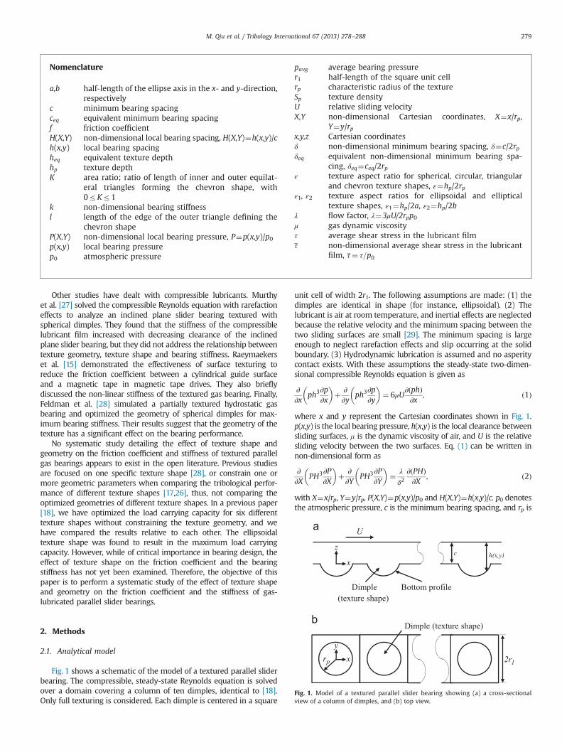
Fig. 1 shows a schematic of the model of a textured parallel sliderbearing. The compressible, steady-state Reynolds equation is solvedover a domain covering a column of ten dimples, identical to [18].Only full texturing is considered. Each dimple is centered in a square
unit cell of width 2r1. The following assumptions are made: (1) thedimples are identical in shape (for instance, ellipsoidal). (2) Thelubricant is air at room temperature, and inertial effects are neglectedbecause the relative velocity and the minimum spacing between thetwo sliding surfaces are small [29]. The minimum spacing is largeenough to neglect rarefaction effects and slip occurring at the solidboundary. (3) Hydrodynamic lubrication is assumed and no asperitycontact exists. With these assumptions the steady-state two-dimen-sional compressible Reynolds equation is given as
∂∂x
ph3∂p∂x
� �þ ∂∂y
ph3∂p∂y
� �¼ 6μU
∂ðphÞ∂x
; ð1Þ
where x and y represent the Cartesian coordinates shown in Fig. 1.p(x,y) is the local bearing pressure, h(x,y) is the local clearance betweensliding surfaces, m is the dynamic viscosity of air, and U is the relativesliding velocity between the two surfaces. Eq. (1) can be written innon-dimensional form as
∂∂X
PH3∂P∂X
� �þ ∂∂Y
PH3∂P∂Y
� �¼ λ
δ2∂ðPHÞ∂X
; ð2Þ
with X¼x/rp, Y¼y/rp, P(X,Y)¼p(x,y)/p0 and H(X,Y)¼h(x,y)/c. p0 denotesthe atmospheric pressure, c is the minimum bearing spacing, and rp is
Nomenclature
a,b half-length of the ellipse axis in the x- and y-direction,respectively
c minimum bearing spacingceq equivalent minimum bearing spacingf friction coefficientH(X,Y) non-dimensional local bearing spacing, H(X,Y)¼h(x,y)/ch(x,y) local bearing spacingheq equivalent texture depthhp texture depthK area ratio; ratio of length of inner and outer equilat-
eral triangles forming the chevron shape, with0rKr1
k non-dimensional bearing stiffnessl length of the edge of the outer triangle defining the
chevron shapeP(X,Y) non-dimensional local bearing pressure, P¼p(x,y)/p0p(x,y) local bearing pressurep0 atmospheric pressure
pavg average bearing pressurer1 half-length of the square unit cellrp characteristic radius of the textureSp texture densityU relative sliding velocityX,Y non-dimensional Cartesian coordinates, X¼x/rp,
Y¼y/rpx,y,z Cartesian coordinatesδ non-dimensional minimum bearing spacing, δ¼c/2rpδeq equivalent non-dimensional minimum bearing spa-
cing, δeq¼ceq/2rpε texture aspect ratio for spherical, circular, triangular
and chevron texture shapes, ε¼hp/2rpε1, ε2 texture aspect ratios for ellipsoidal and elliptical
texture shapes, ε1¼hp/2a, ε2¼hp/2bλ flow factor, λ¼3μU/2rpp0μ gas dynamic viscosityτ average shear stress in the lubricant filmτ non-dimensional average shear stress in the lubricant
film, τ¼ τ=p0
Bottom profile
U
cx
zh(x,y)
Dimple (texture shape)
xy
rp 2r1
Dimple (texture shape)
Fig. 1. Model of a textured parallel slider bearing showing (a) a cross-sectionalview of a column of dimples, and (b) top view.
M. Qiu et al. / Tribology International 67 (2013) 278–288 279
the characteristic radius of the texture shape (see Figs. 1 and A1). Theoperating conditions for the simulation are expressed by the flowfactor λ¼3mU/2rpp0 and the minimum spacing in non-dimensionalform δ¼c/2rp. Atmospheric pressure is maintained at the inlet andoutlet of the solution domain. The presence of adjacent dimples in thespan-wise flow direction (lateral edge) is accounted for with sym-metric boundary conditions, i.e.,
P �r1rp;Y
� �¼ P N�1
2
� �2r1rp
;Y� �
¼ 1; ð3aÞ
∂P∂Y
X;�r1rp
� �¼ ∂P∂Y
X;r1rp
� �¼ 0; ð3bÞ
where N represents the number of unit cells in the column of dimples,and r1 is half the width of a unit cell (see Fig. 1). Eqs. (2), (3a) and (3b)are solved numerically using the finite difference method with centraldiscretization on a staggered grid, and with an over-relaxation factorof 1.4. An error criterion of 0.01% change of pressure at each nodebetween iterations is used to ensure convergence.
2.2. Friction coefficient and bearing stiffness
The friction in the air bearing operating in the hydrodynamiclubrication regime is entirely driven by the shear stress in thelubricant film. The average shear stress is approximated as
τ¼ μUceq
; ð4Þ
where ceq is the equivalent minimum bearing spacing, defined as
ceq ¼ cþheq: ð5Þc represents the minimum bearing spacing (see Fig. 1), and heq is theequivalent texture depth, calculated as the volume of a dimple dividedby the area of its unit cell, (2r1)2. The extra bearing spacing due to thepresence of the texture is thus averaged over the entire bearing
surface. This treatment captures the global effect of reducing thefriction coefficient by means of the texture on an average level, andeffectively predicts the magnitude and trend of the friction coefficientas demonstrated in [15]. A more sophisticated model could includecalculating the local shear stress from the strain rate near the slidingsurface based on the solution of the Reynolds equation, but the formermethod is used since simplicity is preferred here. When definingδeq¼ceq/2rp, Eq. (4) can be re-written in non-dimensional form as
τ¼ λ
3δeq; ð6Þ
where τ¼ τ=p0. Finally, the friction coefficient f can be expressed asthe ratio of the shear stress and the average bearing pressure,
f ¼ τ
pavg�p0¼ τ
Pavg�1: ð7Þ
The stiffness of the air bearing is defined as the derivative ofthe load carrying capacity with respect to the bearing spacing, orin non-dimensional form,
k¼ ∂ðPavg�1Þ∂δ
; ð8Þ
where the load carrying capacity is expressed as the non-dimensional average gauge pressure. To calculate k, the Reynoldsequation is solved to find the average gauge pressure as a functionof bearing spacing δ, and the slope of the curve is determined in adiscrete set of points by a central finite difference scheme.
2.3. Comparison of different texture shapes
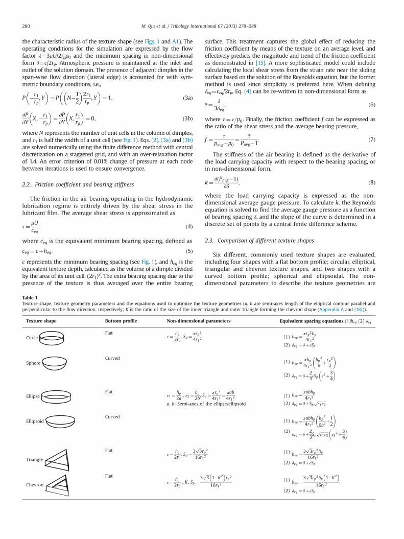
Six different, commonly used texture shapes are evaluated,including four shapes with a flat bottom profile; circular, elliptical,triangular and chevron texture shapes, and two shapes with acurved bottom profile; spherical and ellipsoidal. The non-dimensional parameters to describe the texture geometries are
Table 1Texture shape, texture geometry parameters and the equations used to optimize the texture geometries (a, b are semi-axes length of the elliptical contour parallel andperpendicular to the flow direction, respectively; K is the ratio of the size of the inner triangle and outer triangle forming the chevron shape (Appendix A and [18])).
Texture shape Bottom profile Non-dimensional parameters Equivalent spacing equations (1)heq (2) δeq
CircleFlat
ε¼ hp2rp
, Sp ¼πrp2
4r12(1) heq ¼
πrp2hp
4r12
(2) δeq ¼ δþεSp
SphereCurved
(1) heq ¼πhp
4r12hp
2
6þrp2
2
!
(2) δeq ¼ δþ23εSp ε2þ3
4
� �
EllipseFlat
ε1 ¼hp
2a, ε2 ¼
hp2b
, Sp ¼πrp2
4r12¼ πab4r12
(1) heq ¼πabhp4r12
(2) δeq ¼ δþSpffiffiffiffiffiffiffiffiffiε1ε2
pa, b: Semi-axes of the ellipse/ellipsoid
EllipsoidCurved
(1) heq ¼πabhp4r12
hp2
6b2þ12
!
(2)δeq ¼ δþ2
3Sp
ffiffiffiffiffiffiffiffiffiε1ε2
pε2
2þ34
� �
Triangle
Flatε¼ hp
2rp, Sp ¼
3ffiffiffi3
prp2
16r12(1) heq ¼
3ffiffiffi3
prp2hp
16r12
(2) δeq ¼ δþεSp
Chevron
Flatε¼ hp
2rp, K , Sp ¼
3ffiffiffi3
p1�K2� �
rp2
16r12(1) heq ¼
3ffiffiffi3
prp2hp 1�K2
� �16r12
(2) δeq ¼ δþεSp
M. Qiu et al. / Tribology International 67 (2013) 278–288280
the texture aspect ratio ε, defined as the ratio of the depth and thecharacteristic diameter of the texture feature, and the texturedensity Sp, defined as the ratio of the area covered by the textureand the total area of a unit cell. Two texture aspect ratios, ε1 and ε2,are used for elliptical and ellipsoidal shapes, and an area ratio K isused for the chevron shape (see Appendix A and [18]). All textureshapes with the non-dimensional parameters describing theirgeometry and corresponding equivalent spacing are summarizedin Table 1. The operating conditions in this study are fixed asδ¼0.002 and λ¼2.0�10�5, conditions relevant to several bearingapplications including magnetic tape drives. For each textureshape, the friction coefficient and bearing stiffness are calculatedfor a range of different geometries (ε, Sp) from the numericalsolution of the Reynolds equation. The optimized texture geome-tries resulting in minimum friction coefficient and maximumbearing stiffness, respectively, are identified from the numericalresults for each texture shape and compared relative to each other.
3. Optimization of the geometry of individual texture shapes
3.1. Circular, spherical and triangular texture shapes
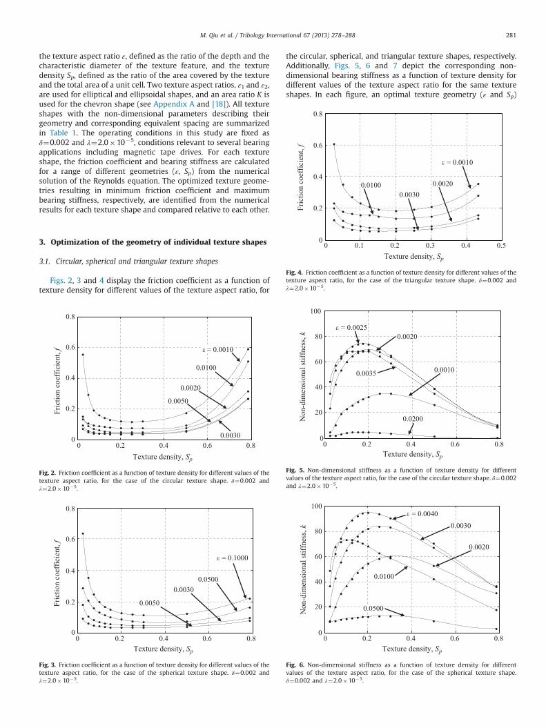
Figs. 2, 3 and 4 display the friction coefficient as a function oftexture density for different values of the texture aspect ratio, for
the circular, spherical, and triangular texture shapes, respectively.Additionally, Figs. 5, 6 and 7 depict the corresponding non-dimensional bearing stiffness as a function of texture density fordifferent values of the texture aspect ratio for the same textureshapes. In each figure, an optimal texture geometry (ε and Sp)
0 0.2 0.4 0.6 0.80
0.2
0.4
0.6
0.8
Texture density, Sp
Fric
tion
coef
ficie
nt, f
� = 0.0010
0.0100
0.0020
0.0030
0.0050
Fig. 2. Friction coefficient as a function of texture density for different values of thetexture aspect ratio, for the case of the circular texture shape. δ¼0.002 andλ¼2.0�10�5.
0 0.2 0.4 0.6 0.80
0.2
0.4
0.6
0.8
Texture density, Sp
Fric
tion
coef
ficie
nt, f
0.05000.0030
0.0050
Fig. 3. Friction coefficient as a function of texture density for different values of thetexture aspect ratio, for the case of the spherical texture shape. δ¼0.002 andλ¼2.0�10�5.
0 0.2 0.4 0.6 0.80
20
40
60
80
100
Texture density, Sp
Non
-dim
ensi
onal
stiff
ness
, k
� = 0.0040
0.0020
0.0100
0.0030
0.0500
Fig. 6. Non-dimensional stiffness as a function of texture density for differentvalues of the texture aspect ratio, for the case of the spherical texture shape.δ¼0.002 and λ¼2.0�10�5.
0 0.2 0.4 0.6 0.80
20
40
60
80
100
Texture density, Sp
Non
-dim
ensi
onal
stiff
ness
, k
0.0020 � = 0.0025
0.0200
0.0010 0.0035
Fig. 5. Non-dimensional stiffness as a function of texture density for differentvalues of the texture aspect ratio, for the case of the circular texture shape. δ¼0.002and λ¼2.0�10�5.
0 0.1 0.2 0.3 0.4 0.50
0.2
0.4
0.6
0.8
Texture density, Sp
Fric
tion
coef
ficie
nt, f
� = 0.0010
0.0020 0.0030
0.0100
Fig. 4. Friction coefficient as a function of texture density for different values of thetexture aspect ratio, for the case of the triangular texture shape. δ¼0.002 andλ¼2.0�10�5.
M. Qiu et al. / Tribology International 67 (2013) 278–288 281
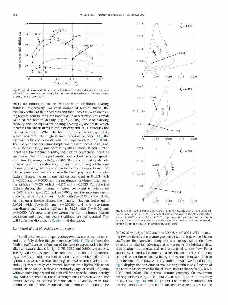
exists for minimum friction coefficient or maximum bearingstiffness, respectively. For each individual texture shape, thefriction coefficient first decreases and then increases with increas-ing texture density, for a constant texture aspect ratio. For a smallvalue of the texture density (e.g., Spo0.05), the load carryingcapacity and the equivalent bearing spacing δeq are small, whichincreases the shear stress in the lubricant and, thus, increases thefriction coefficient. When the texture density exceeds Sp¼0.150,which generates the highest load carrying capacity [18], thefriction coefficient remains low until approximately Sp¼0.300.This is due to the increasing dimple volume with increasing Sp and,thus, increasing δeq and decreasing shear stress. When furtherincreasing the texture density, the friction coefficient increasesagain as a result of the significantly reduced load carrying capacityof textured bearings with Sp40.300. The effect of texture densityon bearing stiffness is directly correlated to the change of the loadcarrying capacity, because a higher load carrying capacity requiresa larger pressure increase to change the bearing spacing. For circulartexture shapes, the minimum friction coefficient is 0.0371 withSp¼0.200 and ε¼0.0030, and the maximum non-dimensional bear-ing stiffness is 74.29 with Sp¼0.175 and ε¼0.0025. For sphericaltexture shapes, the minimum friction coefficient is determinedas 0.0323 with Sp¼0.250 and ε¼0.0050, and the maximum non-dimensional bearing stiffness is 99.05 with Sp¼0.175 and ε¼0.0060.For triangular texture shapes, the minimum friction coefficient is0.0534 with Sp¼0.150 and ε¼0.0030, and the maximumnon-dimensional bearing stiffness is 74.65 with Sp¼0.150 andε¼0.0030. We note that the geometries for minimum frictioncoefficient and maximum bearing stiffness are not identical. Thiswill be further discussed in Section 4 of this paper.
3.2. Elliptical and ellipsoidal texture shapes
The elliptical texture shape requires two texture aspect ratios, ε1and ε2, to fully define the geometry (see Table 1). Fig. 8 shows thefriction coefficient as a function of the texture aspect ratios for theelliptical texture shape, for Sp¼0.175, 0.350 and 0.500, respectively.The Sp values presented here minimize the friction coefficient(Sp¼0.350), and additionally display one case on either side of thisoptimum (Sp¼0.175, 0.500). The range of possible combinations of ε1and ε2 is theoretically constrained because an elliptical/ellipsoidaltexture shape cannot achieve an arbitrarily large or small ε1/ε2 ratiowithout extending beyond the unit cell for a specific texture density[18], which is denoted by the solid straight lines. For each value of thetexture density, an optimal combination of ε1 and ε2 exists thatminimizes the friction coefficient. The optimum is found to be
f¼0.0279 with Sp¼0.350 and ε1¼0.0048, ε2¼0.0021. With increas-ing texture density the texture geometry that minimizes the frictioncoefficient first stretches along the axis orthogonal to the flowdirection to take full advantage of compressing the lubricant flow,thus placing the longitudinal axis orthogonal to the flow. For aspecific Sp the optimal geometry reaches the lateral edge of the unitcell and, when further increasing Sp, the geometry must stretch inthe direction of the flow, which is similar to what we found in [18].Fig. 9 displays the non-dimensional bearing stiffness as a function ofthe texture aspect ratios for the elliptical texture shape, for Sp¼0.175,0.350 and 0.500. The optimal texture geometry for maximumbearing stiffness is Sp¼0.350 and ε1¼0.0029, ε2¼0.0013, resultingin k¼90.67. Figs. 10 and 11 present the friction coefficient andbearing stiffness as a function of the texture aspect ratios for the
0 0.1 0.2 0.3 0.4 0.50
20
40
60
80
100
Texture density, Sp
Non
-dim
ensi
onal
stiff
ness
, k � = 0.0030
0.0020 0.0035
0.0100
0.0010
Fig. 7. Non-dimensional stiffness as a function of texture density for differentvalues of the texture aspect ratio, for the case of the triangular texture shape.δ¼0.002 and λ¼2.0�10�5.
ε2
ε 1
0 0.005 0.010 0.015 0.0200
0.005
0.010
0.015
0.020
ε2
ε 1
0 0.005 0.010 0.015 0.0200
0.005
0.010
0.015
0.020
ε2
ε 1
0 0.005 0.010 0.015 0.0200
0.005
0.010
0.015
0.020
Sp = 0.175
0.034
Sp = 0.350
0.040
0.028
Sp = 0.500
0.050
0.034
Fig. 8. Friction coefficient as a function of different texture aspect ratio combina-tions ε1 and ε2 for Sp¼0.175, 0.350 and 0.500, for the case of the elliptical textureshape. δ¼0.002 and λ¼2.0�10�5. The optimum for each texture density isindicated by “þ”. The range of combinations of ε1 and ε2 that constrains thedimple within the unit cell is denoted by solid lines.
M. Qiu et al. / Tribology International 67 (2013) 278–288282
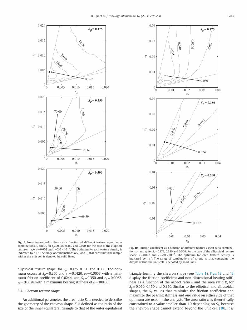
ellipsoidal texture shape, for Sp¼0.175, 0.350 and 0.500. The opti-mum occurs at Sp¼0.350 and ε1¼0.0120, ε2¼0.0053 with a mini-mum friction coefficient of 0.0244, and Sp¼0.350 and ε1¼0.0062,ε2¼0.0028 with a maximum bearing stiffness of k¼108.00.
3.3. Chevron texture shape
An additional parameter, the area ratio K, is needed to describethe geometry of the chevron shape. K is defined as the ratio of thesize of the inner equilateral triangle to that of the outer equilateral
triangle forming the chevron shape (see Table 1). Figs. 12 and 13display the friction coefficient and non-dimensional bearing stiff-ness as a function of the aspect ratio ε and the area ratio K, forSp¼0.050, 0.150 and 0.350. Similar to the elliptical and ellipsoidalshapes, the Sp values that minimize the friction coefficient andmaximize the bearing stiffness and one value on either side of thatoptimum are used in the analysis. The area ratio K is theoreticallyconstrained to a value smaller than 1.0 depending on Sp, becausethe chevron shape cannot extend beyond the unit cell [18]. It is
ε2
ε 1
0 0.005 0.010 0.015 0.0200
0.005
0.010
0.015
0.020
ε2
ε 1
0 0.005 0.010 0.015 0.0200
0.005
0.010
0.015
0.020
ε2
ε 1
0 0.005 0.010 0.015 0.0200
0.005
0.010
0.015
0.020
Sp= 0.175
87.62
Sp= 0.350
90.67
70.00
Sp= 0.500
69.59
50.00
Fig. 9. Non-dimensional stiffness as a function of different texture aspect ratiocombinations ε1 and ε2 for Sp¼0.175, 0.350 and 0.500, for the case of the ellipticaltexture shape. δ¼0.002 and λ¼2.0�10�5. The optimum for each texture density isindicated by “þ”. The range of combinations of ε1 and ε2 that constrains the dimplewithin the unit cell is denoted by solid lines.
ε2
ε 1
0 0.01 0.02 0.03 0.040
0.01
0.02
0.03
0.04
ε2
ε 1
0 0.01 0.02 0.03 0.040
0.01
0.02
0.03
0.04
ε2
ε 1
0 0.01 0.02 0.03 0.040
0.01
0.02
0.03
0.04
Sp = 0.175
0.030
Sp = 0.350
0.024
Sp = 0.500
0.030
0.027
Fig. 10. Friction coefficient as a function of different texture aspect ratio combina-tions ε1 and ε2 for Sp¼0.175, 0.350 and 0.500, for the case of the ellipsoidal textureshape. δ¼0.002 and λ¼2.0�10�5. The optimum for each texture density isindicated by “þ”. The range of combinations of ε1 and ε2 that constrains thedimple within the unit cell is denoted by solid lines.
M. Qiu et al. / Tribology International 67 (2013) 278–288 283
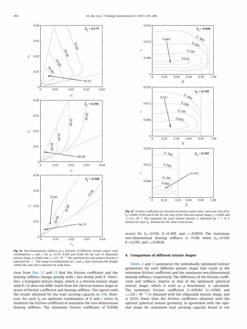
clear from Figs. 12 and 13 that the friction coefficient and thebearing stiffness change quickly with ε but slowly with K. There-fore, a triangular texture shape, which is a chevron texture shapewith K¼0, does not differ much from the chevron texture shape interms of friction coefficient and bearing stiffness. This agrees withthe results obtained for the load carrying capacity in [18]. How-ever, for each Sp an optimum combination of K and ε exists tominimize the friction coefficient or maximize the non-dimensionalbearing stiffness. The minimum friction coefficient of 0.0506
occurs for Sp¼0.150, K¼0.300, and ε¼0.0035. The maximumnon-dimensional bearing stiffness is 75.86 when Sp¼0.150,K¼0.250, and ε¼0.0030.
4. Comparison of different texture shapes
Tables 2 and 3 summarize the individually optimized texturegeometries for each different texture shape that result in theminimum friction coefficient and the maximum non-dimensionalbearing stiffness, respectively. The difference of the friction coeffi-cient and stiffness relative to that of the optimized sphericaltexture shape, which is used as a benchmark, is calculated.The minimum friction coefficient f¼0.0244 (δ¼0.002 andλ¼2.0�10�5) is obtained with the ellipsoidal texture shape, andis 24.5% lower than the friction coefficient obtained with theoptimal spherical texture geometry, in agreement with the opti-mal shape for maximum load carrying capacity found in our
ε2
ε 1
0 0.01 0.02 0.03 0.040
0.01
0.02
0.03
0.04
ε2
ε 1
0 0.01 0.02 0.03 0.040
0.01
0.02
0.03
0.04
ε2
ε 1
0 0.01 0.02 0.03 0.040
0.01
0.02
0.03
0.04
Sp = 0.350
108.00
Sp = 0.175
99.58
Sp = 0.500
70.00
96.19
Fig. 11. Non-dimensional stiffness as a function of different texture aspect ratiocombinations ε1 and ε2 for Sp¼0.175, 0.350 and 0.500, for the case of ellipsoidaltexture shape. δ¼0.002 and λ¼2.0�10�5. The optimum for each texture density isindicated by “þ”. The range of combinations of ε1 and ε2 that constrains the dimplewithin the unit cell is denoted by solid lines.
K
ε
0 0.20 0.40 0.60 0.80 1.000
0.006
0.012
0.018
Kε
0 0.20 0.40 0.60 0.85 1.000
0.006
0.012
0.018
K
ε
0 0.20 0.43 0.60 0.80 1.000
0.006
0.012
0.018
Sp = 0.050
0.064
0.051
Sp = 0.150
0.076
Sp = 0.350
Fig. 12. Friction coefficient as a function of texture aspect ratio ε and area ratio K forSp¼0.050, 0.150 and 0.350, for the case of the chevron texture shape. δ¼0.002 andλ¼2.0�10�5. The optimum for each texture density is indicated by “þ”. K islimited for each Sp, denoted by the solid vertical line.
M. Qiu et al. / Tribology International 67 (2013) 278–288284
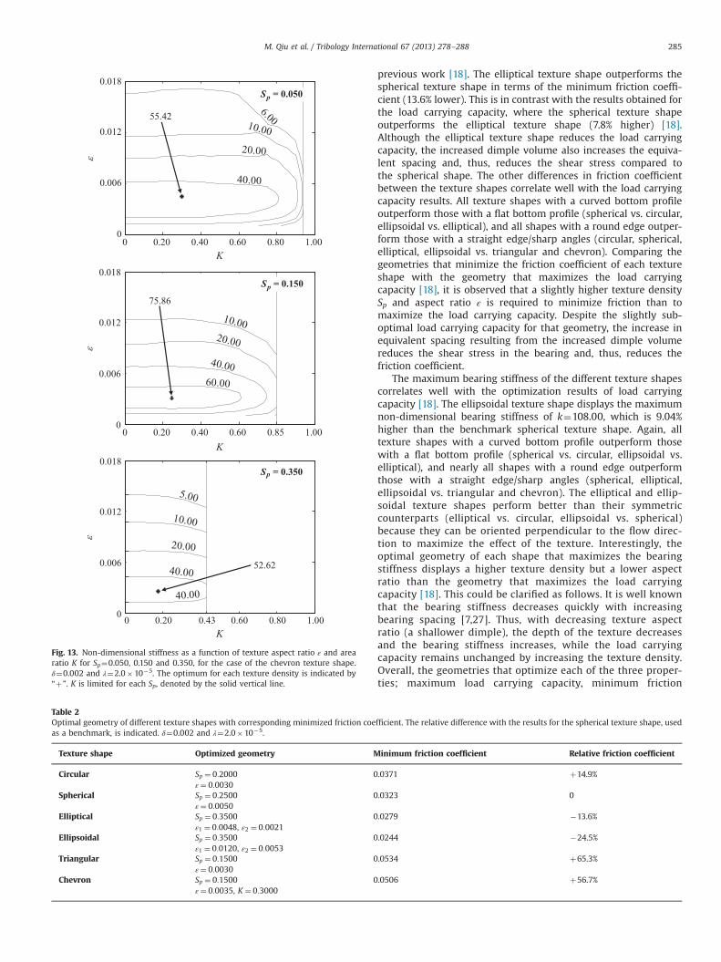
previous work [18]. The elliptical texture shape outperforms thespherical texture shape in terms of the minimum friction coeffi-cient (13.6% lower). This is in contrast with the results obtained forthe load carrying capacity, where the spherical texture shapeoutperforms the elliptical texture shape (7.8% higher) [18].Although the elliptical texture shape reduces the load carryingcapacity, the increased dimple volume also increases the equiva-lent spacing and, thus, reduces the shear stress compared tothe spherical shape. The other differences in friction coefficientbetween the texture shapes correlate well with the load carryingcapacity results. All texture shapes with a curved bottom profileoutperform those with a flat bottom profile (spherical vs. circular,ellipsoidal vs. elliptical), and all shapes with a round edge outper-form those with a straight edge/sharp angles (circular, spherical,elliptical, ellipsoidal vs. triangular and chevron). Comparing thegeometries that minimize the friction coefficient of each textureshape with the geometry that maximizes the load carryingcapacity [18], it is observed that a slightly higher texture densitySp and aspect ratio ε is required to minimize friction than tomaximize the load carrying capacity. Despite the slightly sub-optimal load carrying capacity for that geometry, the increase inequivalent spacing resulting from the increased dimple volumereduces the shear stress in the bearing and, thus, reduces thefriction coefficient.
The maximum bearing stiffness of the different texture shapescorrelates well with the optimization results of load carryingcapacity [18]. The ellipsoidal texture shape displays the maximumnon-dimensional bearing stiffness of k¼108.00, which is 9.04%higher than the benchmark spherical texture shape. Again, alltexture shapes with a curved bottom profile outperform thosewith a flat bottom profile (spherical vs. circular, ellipsoidal vs.elliptical), and nearly all shapes with a round edge outperformthose with a straight edge/sharp angles (spherical, elliptical,ellipsoidal vs. triangular and chevron). The elliptical and ellip-soidal texture shapes perform better than their symmetriccounterparts (elliptical vs. circular, ellipsoidal vs. spherical)because they can be oriented perpendicular to the flow direc-tion to maximize the effect of the texture. Interestingly, theoptimal geometry of each shape that maximizes the bearingstiffness displays a higher texture density but a lower aspectratio than the geometry that maximizes the load carryingcapacity [18]. This could be clarified as follows. It is well knownthat the bearing stiffness decreases quickly with increasingbearing spacing [7,27]. Thus, with decreasing texture aspectratio (a shallower dimple), the depth of the texture decreasesand the bearing stiffness increases, while the load carryingcapacity remains unchanged by increasing the texture density.Overall, the geometries that optimize each of the three proper-ties; maximum load carrying capacity, minimum friction
K
ε
0 0.20 0.40 0.60 0.80 1.000
0.006
0.012
0.018
K
ε
0 0.20 0.40 0.60 0.85 1.000
0.006
0.012
0.018
K
ε
0 0.20 0.43 0.60 0.80 1.000
0.006
0.012
0.018
Sp = 0.050
55.42
Sp = 0.150
75.86
Sp = 0.350
52.62
Fig. 13. Non-dimensional stiffness as a function of texture aspect ratio ε and arearatio K for Sp¼0.050, 0.150 and 0.350, for the case of the chevron texture shape.δ¼0.002 and λ¼2.0�10�5. The optimum for each texture density is indicated by“þ”. K is limited for each Sp, denoted by the solid vertical line.
Table 2Optimal geometry of different texture shapes with corresponding minimized friction coefficient. The relative difference with the results for the spherical texture shape, usedas a benchmark, is indicated. δ¼0.002 and λ¼2.0�10�5.
Texture shape Optimized geometry Minimum friction coefficient Relative friction coefficient
Circular Sp ¼ 0:2000 0.0371 þ14.9%ε¼ 0:0030
Spherical Sp ¼ 0:2500 0.0323 0ε¼ 0:0050
Elliptical Sp ¼ 0:3500 0.0279 �13.6%ε1 ¼ 0:0048, ε2 ¼ 0:0021
Ellipsoidal Sp ¼ 0:3500 0.0244 �24.5%ε1 ¼ 0:0120, ε2 ¼ 0:0053
Triangular Sp ¼ 0:1500 0.0534 þ65.3%ε¼ 0:0030
Chevron Sp ¼ 0:1500 0.0506 þ56.7%ε¼ 0:0035, K ¼ 0:3000
M. Qiu et al. / Tribology International 67 (2013) 278–288 285
coefficient and maximum bearing stiffness are similar but notidentical, consistent with the conclusion of [25].
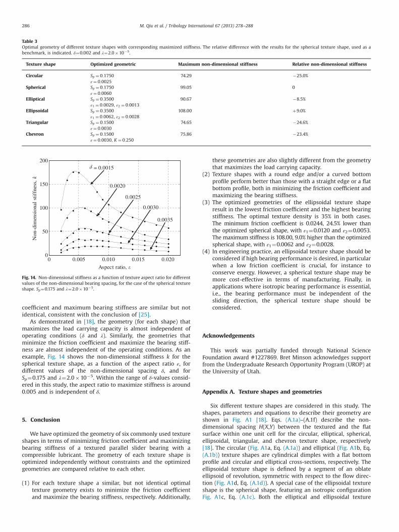
As demonstrated in [18], the geometry (for each shape) thatmaximizes the load carrying capacity is almost independent ofoperating conditions (δ and λ). Similarly, the geometries thatminimize the friction coefficient and maximize the bearing stiff-ness are almost independent of the operating conditions. As anexample, Fig. 14 shows the non-dimensional stiffness k for thespherical texture shape, as a function of the aspect ratio ε, fordifferent values of the non-dimensional spacing δ, and forSp¼0.175 and λ¼2.0�10�5. Within the range of δ-values consid-ered in this study, the aspect ratio to maximize stiffness is around0.005 and is independent of δ.
5. Conclusion
We have optimized the geometry of six commonly used textureshapes in terms of minimizing friction coefficient and maximizingbearing stiffness of a textured parallel slider bearing with acompressible lubricant. The geometry of each texture shape isoptimized independently without constraints and the optimizedgeometries are compared relative to each other.
(1) For each texture shape a similar, but not identical optimaltexture geometry exists to minimize the friction coefficientand maximize the bearing stiffness, respectively. Additionally,
these geometries are also slightly different from the geometrythat maximizes the load carrying capacity.
(2) Texture shapes with a round edge and/or a curved bottomprofile perform better than those with a straight edge or a flatbottom profile, both in minimizing the friction coefficient andmaximizing the bearing stiffness.
(3) The optimized geometries of the ellipsoidal texture shaperesult in the lowest friction coefficient and the highest bearingstiffness. The optimal texture density is 35% in both cases.The minimum friction coefficient is 0.0244, 24.5% lower thanthe optimized spherical shape, with ε1¼0.0120 and ε2¼0.0053.The maximum stiffness is 108.00, 9.0% higher than the optimizedspherical shape, with ε1¼0.0062 and ε2¼0.0028.
(4) In engineering practice, an ellipsoidal texture shape should beconsidered if high bearing performance is desired, in particularwhen a low friction coefficient is crucial, for instance toconserve energy. However, a spherical texture shape may bemore cost-effective in terms of manufacturing. Finally, inapplications where isotropic bearing performance is essential,i.e., the bearing performance must be independent of thesliding direction, the spherical texture shape should beconsidered.
Acknowledgements
This work was partially funded through National ScienceFoundation award #1227869. Bret Minson acknowledges supportfrom the Undergraduate Research Opportunity Program (UROP) atthe University of Utah.
Appendix A. Texture shapes and geometries
Six different texture shapes are considered in this study. Theshapes, parameters and equations to describe their geometry areshown in Fig. A1 [18]. Eqs. (A.1a)–(A.1f) describe the non-dimensional spacing H(X,Y) between the textured and the flatsurface within one unit cell for the circular, elliptical, spherical,ellipsoidal, triangular, and chevron texture shape, respectively[18]. The circular (Fig. A1a, Eq. (A.1a)) and elliptical (Fig. A1b, Eq.(A.1b)) texture shapes are cylindrical dimples with a flat bottomprofile and circular and elliptical cross-sections, respectively. Theellipsoidal texture shape is defined by a segment of an oblateellipsoid of revolution, symmetric with respect to the flow direc-tion (Fig. A1d, Eq. (A.1d)). A special case of the ellipsoidal textureshape is the spherical shape, featuring an isotropic configurationFig. A1c, Eq. (A.1c). Both the elliptical and ellipsoidal texture
Table 3Optimal geometry of different texture shapes with corresponding maximized stiffness. The relative difference with the results for the spherical texture shape, used as abenchmark, is indicated. δ¼0.002 and λ¼2.0�10�5.
Texture shape Optimized geometric Maximum non-dimensional stiffness Relative non-dimensional stiffness
Circular Sp ¼ 0:1750 74.29 �25.0%ε¼ 0:0025
Spherical Sp ¼ 0:1750 99.05 0ε¼ 0:0060
Elliptical Sp ¼ 0:3500 90.67 �8.5%ε1 ¼ 0:0029, ε2 ¼ 0:0013
Ellipsoidal Sp ¼ 0:3500 108.00 þ9.0%ε1 ¼ 0:0062, ε2 ¼ 0:0028
Triangular Sp ¼ 0:1500 74.65 �24.6%ε¼ 0:0030
Chevron Sp ¼ 0:1500 75.86 �23.4%ε¼ 0:0030, K ¼ 0:250
0 0.005 0.010 0.015 0.0200
50
100
150
200
Aspect ratio, �
Non
-dim
ensi
onal
sti
ffne
ss, k
0.0020
= 0.0015
0.0025
0.0030
0.0035
Fig. 14. Non-dimensional stiffness as a function of texture aspect ratio for differentvalues of the non-dimensional bearing spacing, for the case of the spherical textureshape. Sp¼0.175 and λ¼2.0�10�5.
M. Qiu et al. / Tribology International 67 (2013) 278–288286
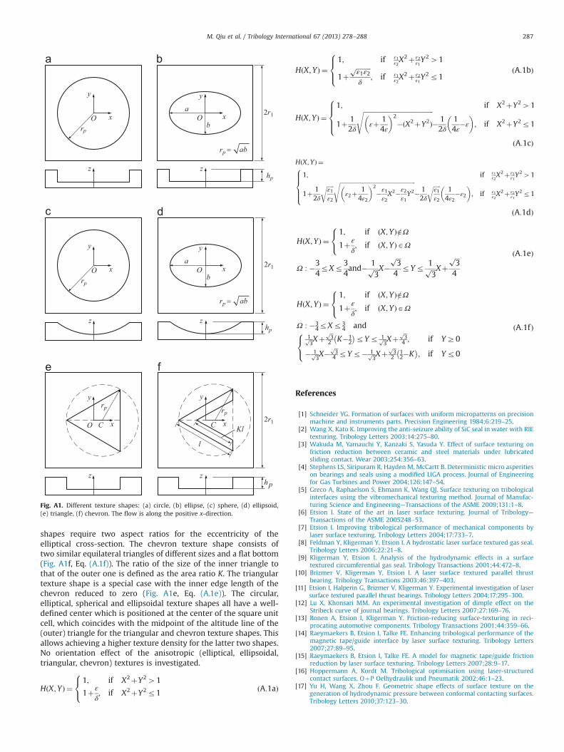
shapes require two aspect ratios for the eccentricity of theelliptical cross-section. The chevron texture shape consists oftwo similar equilateral triangles of different sizes and a flat bottom(Fig. A1f, Eq. (A.1f)). The ratio of the size of the inner triangle tothat of the outer one is defined as the area ratio K. The triangulartexture shape is a special case with the inner edge length of thechevron reduced to zero (Fig. A1e, Eq. (A.1e)). The circular,elliptical, spherical and ellipsoidal texture shapes all have a well-defined center which is positioned at the center of the square unitcell, which coincides with the midpoint of the altitude line of the(outer) triangle for the triangular and chevron texture shapes. Thisallows achieving a higher texture density for the latter two shapes.No orientation effect of the anisotropic (elliptical, ellipsoidal,triangular, chevron) textures is investigated.
HðX;YÞ ¼1; if X2þY241
1þε
δ; if X2þY2r1
8<: ðA:1aÞ
HðX;YÞ ¼1; if ε1
ε2X2þ ε2
ε1Y241
1þffiffiffiffiffiffiffiffiffiε1ε2
pδ
; if ε1ε2X2þ ε2
ε1Y2r1
8><>: ðA:1bÞ
HðX;YÞ ¼1; if X2þY241
1þ 12δ
ffiffiffiffiffiffiffiffiffiffiffiffiffiffiffiffiffiffiffiffiffiffiffiffiffiffiffiffiffiffiffiffiffiffiffiffiffiffiffiffiffiffiffiffiεþ 1
4ε
� �2
�ðX2þY2Þs
� 12δ
14ε
�ε
� �; if X2þY2r1
8>><>>:
ðA:1cÞ
HðX;YÞ ¼1; if ε1
ε2X2þ ε2
ε1Y241
1þ 12δ
ffiffiffiffiffiε1ε2
r ffiffiffiffiffiffiffiffiffiffiffiffiffiffiffiffiffiffiffiffiffiffiffiffiffiffiffiffiffiffiffiffiffiffiffiffiffiffiffiffiffiffiffiffiffiffiffiffiffiffiffiffiffiε2þ
14ε2
� �2
�ε1ε2X2�ε2
ε1Y2
s� 12δ
ffiffiffiffiffiε1ε2
r14ε2
�ε2
� �; if ε1
ε2X2þ ε2
ε1Y2r1
8>>><>>>:
ðA:1dÞ
HðX;YÞ ¼1; if ðX;YÞ=2Ω1þε
δ; if ðX;YÞAΩ
8<:
Ω : �34rXr3
4and� 1ffiffiffi
3p X�
ffiffiffi3
p
4rYr 1ffiffiffi
3p Xþ
ffiffiffi3
p
4
ðA:1eÞ
HðX;YÞ ¼1; if ðX;YÞ=2Ω1þε
δ; if ðX;YÞAΩ
8<:
Ω : �34rXr3
4 and1ffiffi3
p Xþffiffi3
p2 K�1
2
� �rYr 1ffiffi
3p Xþ
ffiffi3
p4 ; if YZ0
� 1ffiffi3
p X�ffiffi3
p4 rYr� 1ffiffi
3p Xþ
ffiffi3
p2
12�K� �
; if Yr0
8<:
ðA:1fÞ
References
[1] Schneider YG. Formation of surfaces with uniform micropatterns on precisionmachine and instruments parts. Precision Engineering 1984;6:219–25.
[2] Wang X, Kato K. Improving the anti-seizure ability of SiC seal in water with RIEtexturing. Tribology Letters 2003;14:275–80.
[3] Wakuda M, Yamauchi Y, Kanzaki S, Yasuda Y. Effect of surface texturing onfriction reduction between ceramic and steel materials under lubricatedsliding contact. Wear 2003;254:356–63.
[4] Stephens LS, Siripuram R, Hayden M, McCartt B. Deterministic micro asperitieson bearings and seals using a modified LIGA process. Journal of Engineeringfor Gas Turbines and Power 2004;126:147–54.
[5] Greco A, Raphaelson S, Ehmann K, Wang QJ. Surface texturing on tribologicalinterfaces using the vibromechanical texturing method. Journal of Manufac-turing Science and Engineering—Transactions of the ASME 2009;131:1–8.
[6] Etsion I. State of the art in laser surface texturing. Journal of Tribology—Transactions of the ASME 2005248–53.
[7] Etsion I. Improving tribological performance of mechanical components bylaser surface texturing. Tribology Letters 2004;17:733–7.
[8] Feldman Y, Kligerman Y, Etsion I. A hydrostatic laser surface textured gas seal.Tribology Letters 2006;22:21–8.
[9] Kligerman Y, Etsion I. Analysis of the hydrodynamic effects in a surfacetextured circumferential gas seal. Tribology Transactions 2001;44:472–8.
[10] Brizmer V, Kligerman Y, Etsion I. A laser surface textured parallel thrustbearing. Tribology Transactions 2003;46:397–403.
[11] Etsion I, Halperin G, Brizmer V, Kligerman Y. Experimental investigation of lasersurface textured parallel thrust bearings. Tribology Letters 2004;17:295–300.
[12] Lu X, Khonsari MM. An experimental investigation of dimple effect on theStribeck curve of journal bearings. Tribology Letters 2007;27:169–76.
[13] Ronen A, Etsion I, Kligerman Y. Friction-reducing surface-texturing in reci-procating automotive components. Tribology Transactions 2001;44:359–66.
[14] Raeymaekers B, Etsion I, Talke FE. Enhancing tribological performance of themagnetic tape/guide interface by laser surface texturing. Tribology Letters2007;27:89–95.
[15] Raeymaekers B, Etsion I, Talke FE. A model for magnetic tape/guide frictionreduction by laser surface texturing. Tribology Letters 2007;28:9–17.
[16] Hoppermann A, Kordt M. Tribological optimisation using laser-structuredcontact surfaces. OþP Oelhydraulik und Pneumatik 2002;46:1–23.
[17] Yu H, Wang X, Zhou F. Geometric shape effects of surface texture on thegeneration of hydrodynamic pressure between conformal contacting surfaces.Tribology Letters 2010;37:123–30.
rp
O x
y
z
O x
y
b
a
hp
2r1
z
rp =
rp
O x
y
z
O x
y
b
a
hp
2r1
z
rp =
rp
O x
y
z
C x
y
rp
l
hp
2r1
z
C Kl
ab
ab
Fig. A1. Different texture shapes: (a) circle, (b) ellipse, (c) sphere, (d) ellipsoid,(e) triangle, (f) chevron. The flow is along the positive x-direction.
M. Qiu et al. / Tribology International 67 (2013) 278–288 287
[18] Qiu M, Delic A, Raeymaekers B. The effect of texture shape on the load-carrying capacity of gas-lubricated parallel slider bearings. Tribology Letters2012;48:315–27.
[19] Nakano M, Korenaga A, Korenaga A, Miyake K, Murakami T, Ando Y, et al.Applying micro-texture to cast iron surfaces to reduce the friction coefficientunder lubricated conditions. Tribology Letters 2007;28:131–7.
[20] Galda L, Pawlus P, Sep J. Dimples shape and distribution effect on character-istics of Stribeck curve. Tribology International 2009;42:1505–12.
[21] Cupillard S, Glavatskih S, Cervantes MJ. Computational fluid dynamics analysisof a journal bearing with surface texturing. Proceedings of the Institution ofMechanical Engineers Part J Journal of Engineering Tribology 2008;222:97–107.
[22] Dobrica MB, Fillon M, Pascovici MD, Cicone T. Optimizing surface texture forhydrodynamic lubricated contacts using a mass-conserving numericalapproach. Proceedings of the Institution of Mechanical Engineers Part JJournal of Engineering Tribology 2010;224:737–50.
[23] Ma C, Zhu H. An optimum design model for textured surface with elliptical-shaped dimples under hydrodynamic lubrication. Tribology International2011;44:987–95.
[24] Sahlin F, Glavatskih SB, Almqvist T, Larsson R. Two-dimensional CFD-analysisof micro-patterned surfaces in hydrodynamic lubrication. Journal of Tribology—Transactions of the ASME 2005;127:96–102.
[25] Pascovici MD, Cicone T, Fillon M, Dobrica MB. Analytical investigation of apartially textured parallel slider. Proceedings of the Institution of MechanicalEngineers Part J Journal of Engineering Tribology 2009;223:151–8.
[26] Siripuram RB, Stephens LS. Effect of deterministic asperity geometry onhydrodynamic lubrication. Journal of Tribology—Transactions of the ASME,126; 527–34.
[27] Murthy AN, Etsion I, Talke FE. Analysis of surface textured air bearing sliderswith rarefaction effects. Tribology Letters 2007;28:251–61.
[28] Feldman Y, Kligerman Y, Etsion I. Stiffness and efficiency optimization of ahydrostatic laser surface textured gas seal. Journal of Tribology—Transactionsof the ASME, 129; 407–10.
[29] Raeymaekers B, Etsion I, Talke FE. The influence of operating and designparameters on the magnetic tape/guide friction coefficient. Tribology Letters2006;25:161–71.
M. Qiu et al. / Tribology International 67 (2013) 278–288288