Embed Size (px)
Citation preview
ILASS – Europe 2010, 23rd Annual Conference on Liquid Atomization and Spray Systems, Brno, Czech Republic, September 2010
1
The Effect of Swirl on Air / Fuel Mixing in a 4 Valve GDI Engine
G. Pitcher1, G. Wigley2, P. Stansfield3, R. Patel1 1. Lotus Engineering Ltd, Hethel, Norwich, UK,
2. Aeronautical and Automotive Engineering, Loughborough University, Leicestershire, UK 3. Mahle Powertrain Ltd, Northampton, UK
Abstract The effect on fuel consumption and emissions of switching from two-valve to single-valve EIVC operation in order to generate swirl intake structures in a four-valve, pent-roof gasoline direct injection (GDI) engine has been investigated. Mie imaging of the fuel spray propagation, along with PIV measurements of the intake flow field have been taken in an optical engine, and fuel economy and emissions measurements have been made on a thermodynamic engine with identical geometry and ancillary systems. The measurements show that fuel economy can be improved substantially when EIVC valve operation is em-ployed, and results differ when only a single inlet valve is activated. Bulk swirl structures are generated in the engine cylinder which affect the atomisation and transportation of the fuel spray and engine performance. For fuel injection after the inlet valve closing point, the reduction in shear forces and mixing from the intake air structures is sufficient to cause engine misfires.
Introduction During the 1990s, the European Commission secured voluntary agreements with European car manufactur-
ers (ACEA) to reduce CO2 emissions from new vehicles to 140 g/km from 2008/09 [1] . Fully variable valve timing (FVVT) can help to improve engine efficiency by reducing the pumping losses during the engine cycle under part load operation.
One FVVT strategy to reduce the throttling losses at part load is Early Inlet Valve Closing (EIVC) [3]. This allows the engine to operate with a wider open throttle during a restricted valve opening period to limit the total mass of air inducted. Furthermore, FVVT offers the possibility to de-activate one of the inlet valves in a multiple inlet valve engine during the induction stroke. This offers the possibility of load control alongside the generation of a swirling intake air motion in the cylinder, in contrast to the usual tumble structures.
The spray plume development and penetration from an engine’s direct injection fuel injectors are known to be highly dependent upon the in-cylinder air structures and hence the spray propagation. Therefore, the fuel-air mixing characteristics and engine performance are likely to be significantly affected by changes in the valve tim-ing profiles [4].
This study aims to investigate how the fuel consumption and emissions are affected when the valve profiles are switched from twin-valve to single-valve EIVC operation. The effect on the fuel spray development has been investigated by Mie imaging and the magnitude of the swirl structures induced has been quantified using the Particle Image Velocimetry (PIV) technique.
Research Engines Two research engines, one featuring extensive optical access and the other designed for analysing thermo-
dynamic performance, were fitted with identical combustion chamber geometries (Table 1) and identical inlet and exhaust systems. Engine diagnostic equipment was duplicated on both engines. These engines were used to study the effect of air intake structures on engine performance, fuel consumption and emissions. These engines have been described by Stansfield et al. (2007) [1].
Table 1: Research Engines
Bore: 88.0 mm Stroke: 82.1 mm Compression Ratio: 10:1 Speed: 2000 rpm Load: 2.7 bar IMEP720 AFR Stoichiometric Injection: 6-Stream Direct Injection Gasoline
_____________________________ * Corresponding author: [email protected]
ILASS – Europe 2010 The Effect of Swirl on Air / Fuel Mixing in a 4 Valve GDI Engine
2
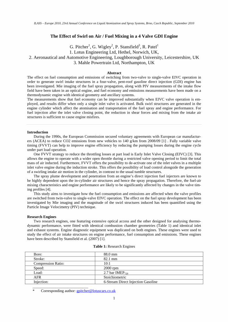
The two engines were operated at the same speed load point of 2000 rpm and 2.7 bar IMEP720° under EIVC conditions with a wide open throttle. The valve profiles, which were calculated on a 1D engine simulation code and verified on both engines, are shown in Figure 1. The conventional intake and exhaust profiles, were both identical featuring a maximum lift of 9.35 mm and duration of 240 CAD. For two valve EIVC operation, the duration was reduced to 115 CAD and correspondingly the lift to 1.7 mm. Similarly for single valve operation, the lift was restricted to 2.1 mm and duration to 137 CAD. These profiles provided sufficient time area for the engine to operate un-throttled at the required speed and load point of 2000 rev/min 2.7 bar IMEP. The savings which can be realised from controlling the engine load with valve events instead of a throttle are clearly demon-strated in Figure 2, which shows the much smaller pumping loops on the pressure/volume diagram with early inlet valve closing.
0123456789
10
0 90 180 270 360 450 540 630 720Crank Angle Duration [CAD]
Valv
e Li
ft [m
m]
9.1 mm 240 CADExhaust9.1 mm 240 CADIntake2.1 mm 137 CAD
1.7 mm 115 CAD
0.1
1
10
100
10 100 1000
Cylinder Volume [cc]
Cyl
inde
r Pre
ssur
e [b
ar]
9.1 mm V1+V3
2.1 mm V1
1.7 mm V1+V3
Figure 1. Valve Profiles Figure 2. Pressure/volume diagrams
Thermodynamic Engine Measurements The thermodynamic engine, which ran a mechanical valve train, was used to measure fuel consumption,
emissions and indicated power for a range of fuel injection timings. Fuel consumption was evaluated using an AVL 733 gravimetric fuel balance with a sampling time of 3 minutes. The exhaust gas was sampled 250 mm downstream of the manifold in the exhaust plenum and a thermostatically controlled heated sample line was used to transmit the exhaust gas to the analysis equipment. Standard bench emissions were measured these being NOx, THC and CO. At each engine condition, the fuel pulse width was adjusted to achieve for stoichiometric combustion as indicated by a heated oxygen sensor mounted in the exhaust plenum. Spark advance was adjusted for Minimum advance for best torque (MBT). Cylinder pressure measurements were made using a Kistler 6041A pressure transducer mounted on the periphery of the combustion chamber in between the intake and exhaust valves. 300 combustion cycles were recorded in order to obtain suitably representative data for the conditions investigated. Cylinder pressure was pegged at TDC valve-overlap with a water cooled transducer mounted in the exhaust manifold. Fuel pressure was maintained at 120 bar for all tests conducted by an independently driven pump.
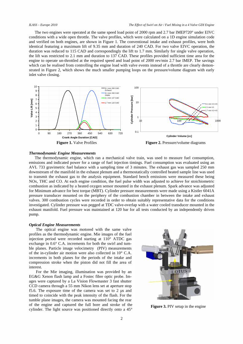
Optical Engine Measurements The optical engine was motored with the same valve
profiles as the thermodynamic engine. Mie images of the fuel injection period were recorded starting at 110° ATDC gas exchange in 0.6° C.A. increments for both the swirl and tum-ble planes. Particle image velocimetry (PIV) measurements of the in-cylinder air motion were also collected in 10° C.A. increments in both planes for the periods of the intake and compression stroke when the piston did not fill the area of interest.
For the Mie imaging, illumination was provided by an EG&G Xenon flash lamp and a Fostec fibre optic probe. Im-ages were captured by a La Vision Flowmaster 3 fast shutter CCD camera through a 55 mm Nikon lens set at aperture stop f5.6. The exposure time of the camera was set to 2 µs and timed to coincide with the peak intensity of the flash. For the tumble plane images, the camera was mounted facing the rear of the engine and captured the full bore and stroke of the cylinder. The light source was positioned directly onto a 45°
Figure 3. PIV setup in the engine
ILASS – Europe 2010 The Effect of Swirl on Air / Fuel Mixing in a 4 Valve GDI Engine
3
mirror positioned between the struts of the bifurcated piston to allow light to enter the cylinder from below through a 56 mm diameter sapphire window in the piston crown. For the swirl plane measurements, the camera was positioned facing the 45° mirror and the flash panel was directed through the cylinder liner.
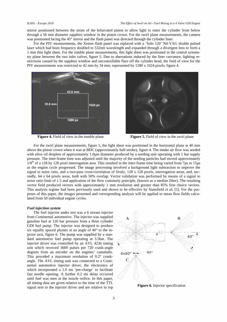
For the PIV measurements, the Xenon flash panel was replaced with a ‘Solo 120’ Nd-YAG double pulsed laser which had been frequency doubled to 532nm wavelength and expanded through a divergent lens to form a 1 mm thin light sheet. For the tumble plane measurements, this light sheet was positioned in the central symme-try plane between the two inlet valves, figure 5. Due to aberrations induced by the liner curvature, lighting re-strictions caused by the sapphire window and uncontrollable flare off the cylinder head, the field of view for the PIV measurements was restricted to 42 mm by 34 mm, represented by 1280 x 1024 pixels, figure 4.
Figure 4. Field of view in the tumble plane Figure 5. Field of view in the swirl plane
For the swirl plane measurements, figure 5, the light sheet was positioned in the horizontal plane at 40 mm
above the piston crown when it was at BDC (approximately half stroke), figure 4. The intake air flow was seeded with olive oil droplets of approximately 1.0µm diameter produced by a seeding unit operating with 1 bar supply pressure. The inter-frame time was adjusted until the majority of the seeding particles had moved approximately 1/8th of a 128 by 128 pixel interrogation area. This resulted in the inter-frame time being varied from 7µs to 15µs as the engine cycle progressed. The image processing involved a background light subtraction to improve the signal to noise ratio, and a two-pass cross-correlation of firstly, 128 x 128 pixels, interrogation areas, and, sec-ondly, 64 x 64 pixels areas, both with 50% overlap. Vector validation was performed by means of a signal to noise ratio limit of 1.5 and application of the flow continuity principle, (known as a median filter). The resulting vector field produced vectors with approximately 1 mm resolution and greater than 85% first choice vectors. This analysis regime had been previously used and shown to be effective by Stansfield et al, [5]. For the pur-poses of this paper, the images presented and corresponding analysis will be applied to mean flow fields calcu-lated from 50 individual engine cycles.
Fuel injection system The fuel injector under test was a 6 stream injector
from Continental automotive. The injector was supplied gasoline fuel at 120 bar pressure from a three cylinder GDI fuel pump. The injector was designed to produce six equally spaced plumes at an angle of 40° to the in-jector axis, figure 6. The pump was supplied by a stan-dard automotive fuel pump operating at 3.5bar. The injector driver was controlled by an AVL 4236 timing unit which received 3600 pulses per 720 crank-angle degrees from an encoder on the engines’ camshafts. This provided a maximum resolution of 0.2° crank-angle. The AVL timing unit was connected to a Conti-nental automotive injector driver, the electronics of which incorporated a 1.0 ms ‘pre-charge’ to facilitate fast needle opening. A further 0.2 ms delay occurred until fuel was seen at the nozzle orifice. In this paper, all timing data are given relative to the time of the TTL signal sent to the injector driver and are relative to top
6x60° 90°
40°
A
C
B
Figure 6. Injector specification
ILASS – Europe 2010 The Effect of Swirl on Air / Fuel Mixing in a 4 Valve GDI Engine
4
dead centre compression. To compare the effect of swirl on the fuel spray, Mie
images were first taken on an atmospheric spray bench into quiescent air. These results have been reported by Stans-field et al, [4]. The images show the two outermost plumes in the focal plane of the camera, and two plumes, one propagating towards and one propagating away from the camera, on each side of the injector axis, figure 7.
This view corresponds to the orientation in the optical engine, with the exception of the 10° off-vertical mounting angle, present in the packaging of the injector within the engine’s cylinder head, which directed the plumes towards the camera.
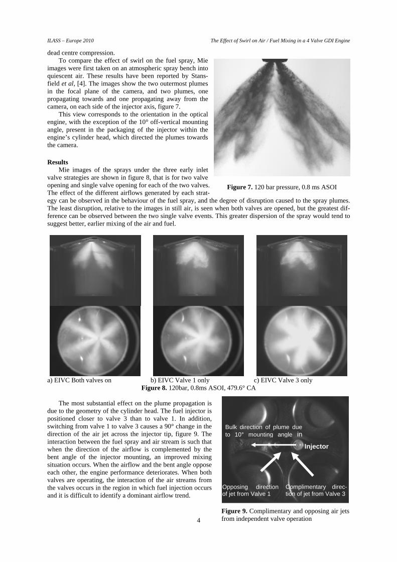
Results Mie images of the sprays under the three early inlet
valve strategies are shown in figure 8, that is for two valve opening and single valve opening for each of the two valves. The effect of the different airflows generated by each strat-egy can be observed in the behaviour of the fuel spray, and the degree of disruption caused to the spray plumes. The least disruption, relative to the images in still air, is seen when both valves are opened, but the greatest dif-ference can be observed between the two single valve events. This greater dispersion of the spray would tend to suggest better, earlier mixing of the air and fuel.
a) EIVC Both valves on b) EIVC Valve 1 only c) EIVC Valve 3 only
Figure 8. 120bar, 0.8ms ASOI, 479.6° CA
The most substantial effect on the plume propagation is due to the geometry of the cylinder head. The fuel injector is positioned closer to valve 3 than to valve 1. In addition, switching from valve 1 to valve 3 causes a 90° change in the direction of the air jet across the injector tip, figure 9. The interaction between the fuel spray and air stream is such that when the direction of the airflow is complemented by the bent angle of the injector mounting, an improved mixing situation occurs. When the airflow and the bent angle oppose each other, the engine performance deteriorates. When both valves are operating, the interaction of the air streams from the valves occurs in the region in which fuel injection occurs and it is difficult to identify a dominant airflow trend.
Figure 7. 120 bar pressure, 0.8 ms ASOI
Complimentary direc-tion of jet from Valve 3
Bulk direction of plume due to 10° mounting angle in
Opposing direction of jet from Valve 1
Injector
Figure 9. Complimentary and opposing air jets from independent valve operation
ILASS – Europe 2010 The Effect of Swirl on Air / Fuel Mixing in a 4 Valve GDI Engine
5
Valve 1 On Only Both Valves On Valve 3 On Only
444.8°
454.8°
464.8°
474.8°
484.8°
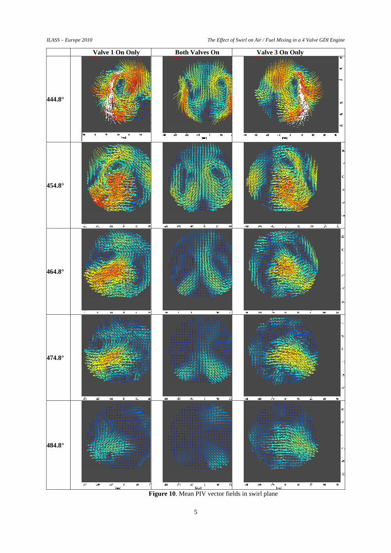
Figure 10. Mean PIV vector fields in swirl plane
ILASS – Europe 2010 The Effect of Swirl on Air / Fuel Mixing in a 4 Valve GDI Engine
6
The flow fields associated with each strategy, at several crank-angle positions are shown in figure 10. The opposite swirling flow directions for each single valve can be clearly identified, with the two valve strategy showing two counter rotating vortices. One of the significant differences between the single valve and two valve strategies is that for two valves the mean flow decays earlier in the engine cycle and this is turn means that the turbulent kinetic energy generated from this decay will dissipate earlier in the cycle leaving less available at the time of combustion. This would be expected to have an effect on the combustion behaviour in the engine and this was investigated using the thermodynamic engine.
The PIV technique produces mean flow fields which can be used to quantify the level of swirl generated in the cylinder. A common technique to achieve this is the calculation of the swirl ratio. Several techniques are available for calculating the swirl ratio, [6], of which one of the most common assumes conservation of angular momentum.
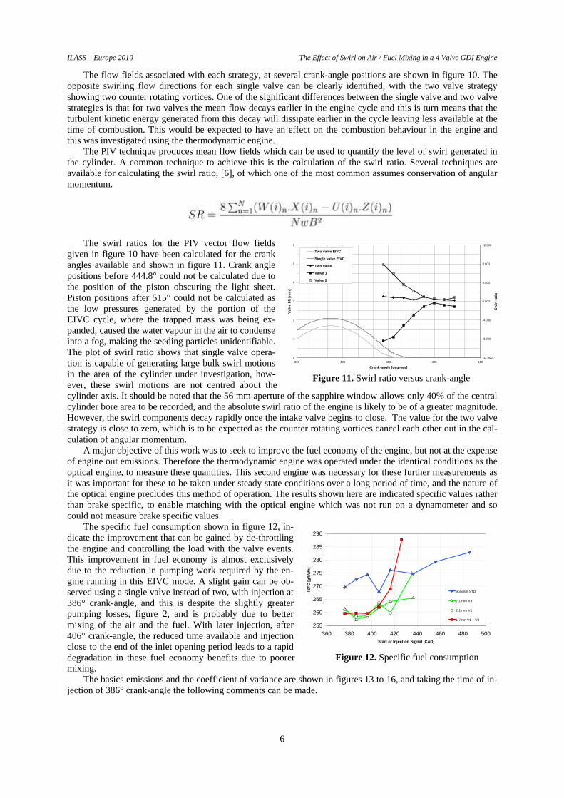
The swirl ratios for the PIV vector flow fields given in figure 10 have been calculated for the crank angles available and shown in figure 11. Crank angle positions before 444.8° could not be calculated due to the position of the piston obscuring the light sheet. Piston positions after 515° could not be calculated as the low pressures generated by the portion of the EIVC cycle, where the trapped mass was being ex-panded, caused the water vapour in the air to condense into a fog, making the seeding particles unidentifiable. The plot of swirl ratio shows that single valve opera-tion is capable of generating large bulk swirl motions in the area of the cylinder under investigation, how-ever, these swirl motions are not centred about the cylinder axis. It should be noted that the 56 mm aperture of the sapphire window allows only 40% of the central cylinder bore area to be recorded, and the absolute swirl ratio of the engine is likely to be of a greater magnitude. However, the swirl components decay rapidly once the intake valve begins to close. The value for the two valve strategy is close to zero, which is to be expected as the counter rotating vortices cancel each other out in the cal-culation of angular momentum.
A major objective of this work was to seek to improve the fuel economy of the engine, but not at the expense of engine out emissions. Therefore the thermodynamic engine was operated under the identical conditions as the optical engine, to measure these quantities. This second engine was necessary for these further measurements as it was important for these to be taken under steady state conditions over a long period of time, and the nature of the optical engine precludes this method of operation. The results shown here are indicated specific values rather than brake specific, to enable matching with the optical engine which was not run on a dynamometer and so could not measure brake specific values.
The specific fuel consumption shown in figure 12, in-dicate the improvement that can be gained by de-throttling the engine and controlling the load with the valve events. This improvement in fuel economy is almost exclusively due to the reduction in pumping work required by the en-gine running in this EIVC mode. A slight gain can be ob-served using a single valve instead of two, with injection at 386° crank-angle, and this is despite the slightly greater pumping losses, figure 2, and is probably due to better mixing of the air and the fuel. With later injection, after 406° crank-angle, the reduced time available and injection close to the end of the inlet opening period leads to a rapid degradation in these fuel economy benefits due to poorer mixing.
The basics emissions and the coefficient of variance are shown in figures 13 to 16, and taking the time of in-jection of 386° crank-angle the following comments can be made.
Figure 11. Swirl ratio versus crank-angle
0
1
2
3
4
5
6
360 405 450 495 540
Crank-angle [degrees]
Valv
e lif
t [m
m]
-12.000
-8.000
-4.000
0.000
4.000
8.000
12.000
Swirl
ratio
Two valve EIVC
Single valve EIVC
Two valve
Valve 1
Valve 2
255
260
265
270
275
280
285
290
360 380 400 420 440 460 480 500Start of Injection Signal [CAD]
ISFC
[g/k
Wh]
9.35mm STD
2.1 mm V3
2.1 mm V1
1.7mm V1 + V3
Figure 12. Specific fuel consumption
ILASS – Europe 2010 The Effect of Swirl on Air / Fuel Mixing in a 4 Valve GDI Engine
7
2
3
4
5
6
7
8
9
360 380 400 420 440 460 480 500 520 540Start of Injection Signal [CAD]
ISTH
C [g
/kW
h]
9.1 mm V1+V3
2.1 mm V3
2.1 mm V1
1.7 mm V1+V3
05
101520253035404550
360 380 400 420 440 460 480 500 520 540Start of Injection Signal [CAD]
ISC
O [g
/kW
h]
9.35mm STD
1.7mm V1 + V3
2.1 mm V3
2.1 mm V1
Figure 13. Total Hydro-Carbons Figure 14. Carbon Monoxide
0123456789
10
360 380 400 420 440 460 480 500 520 540Start of Injection Signal [CAD]
ISN
Ox
[g/k
Wh]
9.35mm STD
1.7mm V1 + V3
2.1 mm V3
2.1 mm V1
02468
101214161820
360 380 400 420 440 460 480 500 520 540Start of Injection Signal [CAD]
CoV
of I
MEP
[%]
9.35mm STD
1.7mm V1 + V3
2.1 mm V3
2.1 mm V1
Figure 15. Nitrous Oxides Figure 16. Coefficient of Variance
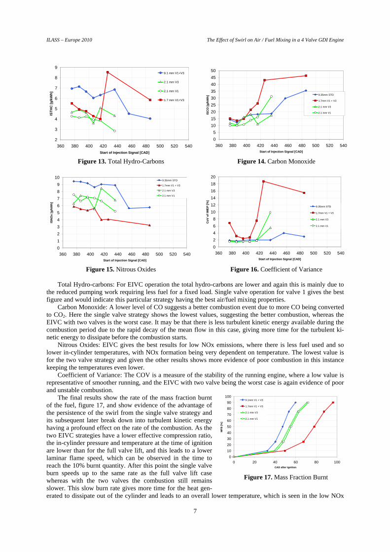
Total Hydro-carbons: For EIVC operation the total hydro-carbons are lower and again this is mainly due to
the reduced pumping work requiring less fuel for a fixed load. Single valve operation for valve 1 gives the best figure and would indicate this particular strategy having the best air/fuel mixing properties.
Carbon Monoxide: A lower level of CO suggests a better combustion event due to more CO being converted to CO2. Here the single valve strategy shows the lowest values, suggesting the better combustion, whereas the EIVC with two valves is the worst case. It may be that there is less turbulent kinetic energy available during the combustion period due to the rapid decay of the mean flow in this case, giving more time for the turbulent ki-netic energy to dissipate before the combustion starts.
Nitrous Oxides: EIVC gives the best results for low NOx emissions, where there is less fuel used and so lower in-cylinder temperatures, with NOx formation being very dependent on temperature. The lowest value is for the two valve strategy and given the other results shows more evidence of poor combustion in this instance keeping the temperatures even lower.
Coefficient of Variance: The COV is a measure of the stability of the running engine, where a low value is representative of smoother running, and the EIVC with two valve being the worst case is again evidence of poor and unstable combustion.
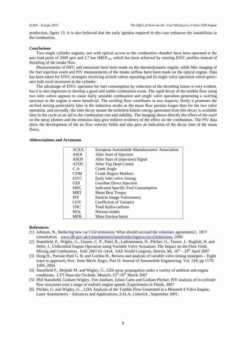
The final results show the rate of the mass fraction burnt of the fuel, figure 17, and show evidence of the advantage of the persistence of the swirl from the single valve strategy and its subsequent later break down into turbulent kinetic energy having a profound effect on the rate of the combustion. As the two EIVC strategies have a lower effective compression ratio, the in-cylinder pressure and temperature at the time of ignition are lower than for the full valve lift, and this leads to a lower laminar flame speed, which can be observed in the time to reach the 10% burnt quantity. After this point the single valve burn speeds up to the same rate as the full valve lift case whereas with the two valves the combustion still remains slower. This slow burn rate gives more time for the heat gen-erated to dissipate out of the cylinder and leads to an overall lower temperature, which is seen in the low NOx
0102030405060708090
100
0 20 40 60 80 100CAD after Ignition
MFB
[%]
9.1mm V1 + V3
1.7mm V1 + V3
2.1 mm V3
2.1 mm V1
Figure 17. Mass Fraction Burnt
ILASS – Europe 2010 The Effect of Swirl on Air / Fuel Mixing in a 4 Valve GDI Engine
8
production, figure 15. It is also believed that the early ignition required in this case enhances the instabilities in the combustion.
Conclusions Two single cylinder engines, one with optical access to the combustion chamber have been operated at the
part load point of 2000 rpm and 2.7 bar IMEP720, which has been achieved by running EIVC profiles instead of throttling of the intake flow.
Measurements of ISFC and emissions have been made on the thermodynamic engine, while Mie imaging of the fuel injection event and PIV measurements of the intake airflow have been made on the optical engine. Data has been taken for EIVC strategies involving a) both valves operating and b) single valve operation which gener-ates bulk swirl structures in the cylinder.
The advantage of EIVC operation for fuel consumption by reduction of the throttling losses is very evident, but it is also important to develop a good and stable combustion event. The rapid decay of the tumble flow using two inlet valves appears to cause fairly unstable combustion and single valve operation generating a swirling structure in the engine is more beneficial. The swirling flow contributes in two respects: firstly it promotes the air/fuel mixing particularly later in the induction stroke as the mean flow persists longer than for the two valve operation, and secondly, the later decay means the turbulent kinetic energy generated from this decay is available later in the cycle as an aid to the combustion rate and stability. The imaging shows directly the effect of the swirl on the spray plumes and the emission data give indirect evidence of the effect on the combustion. The PIV data show the development of the air flow velocity fields and also give an indication of the decay time of the mean flows.
Abbreviations and Acronyms
ACEA European Automobile Manufacturers' Association ASOI After Start of Injection ASOS After Start of (injection) Signal ATDC After Top Dead Centre C.A. Crank Angle CDM Crank Degree Markers EIVC Early inlet valve closing GDI Gasoline Direct Injection ISFC Indicated Specific Fuel Consumption MBT Mean Best Torque PIV Particle Image Velocimetry COV Coefficient of Variance THC Total hydro-carbons NOx Nitrous oxides MFB Mass fraction burnt
References [1] Johnson, N., Reducing new car CO2 emissions: What should succeed the voluntary agreements?, DFT
consultation, www.dft.gov.uk/consultations/closed/reducingnewcarco2emissions, 2006 [2] Stansfield, P., Wigley, G., Garner, C. P., Patel, R., Ladommatos, N., Pitcher, G., Turner, J., Nuglish, H. and
Helie, J., Unthrottled Engine Operation using Variable Valve Actuation: The Impact on the Flow Field, Mixing and Combustion, SAE 2007-01-1414, SAE World Congress, Detroit, Mi, 16th – 19th April 2007
[3] Hong H., Parvate-Patil G. B. and Gordon B., Review and analysis of variable valve timing strategies – Eight ways to approach, Proc. Instn Mech. Engrs. Part D: Journal of Automobile Engineering, Vol. 218, pp 1179-1200, 2004
[4] Stansfield P., Mojtabi M. and Wigley, G., GDI spray propagation under a variety of ambient and engine conditions, LTT Haus-der-Technik, Munich, 15th-16th March 2007
[5] Phil Stansfield, Graham Wigley, Tim Justham, Julian Catto and Graham Pitcher, PIV analysis of in-cylinder flow structures over a range of realistic engine speeds, Experiments in Fluids, 2007
[6] Pitcher, G. and Wigley, G.., LDA Analysis of the Tumble Flow Generated in a Motored 4 Valve Engine, Laser Anemometry - Advances and Applications, EALA, Limerick , September 2001.