Embed Size (px)
Citation preview
The Effect of Reduced Evaporator Air Flow on the Performance of a Residential Central Air Conditioner
Manivannan Palani Dr. Dennis O'Neal Dr. Jeff Haberl Energy Systems Laboratory
Mechanical Engineering Department Texas A&M University
ABSTRACT
This paper discusses the measured degradation in performance of a residential air conditioning system operating under reduced evaporator air flow. Experiments were conducted using a R-22 three-ton split-type cooling system with a short-tube orifice expansion device. Results are presented here for a series of tests in which the evaporator air flow was reduced from 25 to 90% below what is normally recommended for this air conditioner.
At present, very little information is available which quantifies the performance of a residential cooling system operating under degraded conditions such as reduced evaporator air flow. Degraded performance measurements can provide information which could help electric utilities evaluate the potential impact of system-wide maintenance programs.
INTRODUCTION
Energy use in heating and cooling systems represents 20% of the energy use in the residential sector[ I]. Approximately 30.7 million central system air conditioners are used in residences[2]. Each year, 4 million new units are installed[3]. The average life of a residential unit is about 15 years[4]. Equipment service and replacement costs represent 40% of residential HVAC trade. In 1988, alone $2.75 billion was spent on residential HVAC maintenance and repair. A typical hourly rate in the residential cooling market costs $40 per hour[5]. One of the major problems facing the residential cooling service industry is a lack of adequately trained service technicians[6]. At the root of the problem is the fact that diagnostic techniques are typically based on the experience of the service personnel and remedial measures vary widely with each individual's ba<.:kground.
The demand for morc efficient air conditioners is currently increasing, prompted by the fact that residential energy costs have increased by 200% in the last 15 years[7]. This trend was accelerated by the Appliance Minimum Efficiency Standard, which became effective in 1992[8]. Utilities are also being asked to increase and measure their demand-side savings. However, simply installing an high efficient air conditioner does not always mean reduced energy use. The net effect is that air conditioning installers and servicemen are being asked to look at much more than just installing and charging the system.
Air Conditionine Installation and Service The benefits from a high efficiency air conditioner will be
reduced unless it is properly installed and maintained. Field studies show that many of the existing installations are of poor
quality and require immediate service to save the equipment or to restore it to rated efficiency[9, 10]. Experts from air conditioning service industry also point out that manufacturers are not addressing the difficulties that arise in field installations[ll].
Need for Preventive Maintenance and Diaenosis System Current trends in the air conditioning service industry are
based on corrective maintenance procedures which are initiated only after a failure occurs. Preventive maintenance is rarely used. Some possible reasons include: (I) customers' reluctance to pay, and (2) contractors' lack of the necessary knowledge to . provide an effective preventive maintenance procedure.
Preventive maintenance can be primarily classified as [12]: (1) On Condition Maintenance (OCM) where degradation prior to functional failure can be detected by periodic inspections and evaluations, or (2) Condition Monitoring (CM) where degradation prior to functional failure can be detected in sufficient time by instrumentation(e.g., temperature or pressure).
Regardless of which approach is followed preventive maintenance is only effective when potential failures can be ascertained reliably and inexpensively and where the prevention of the failure more than pays for the diagnosis. To predict the shortfall between performance and standards, it is necessary to develop a criteria which are capable of re<.:ognizing the degraded conditions.
Objective of Current Investication Currently, very lillIe information is available which
describes the expected performance of air conditioners under degraded conditions. The air conditioning industry has shown a concern regarding this and several trade journal articles address this issue [13,14]. This problem is further compounded by a lack of consensus for developing proper service procedures[ 15].
The primary focus of this work is to measure energy consumption, cooling capacity and energy efficiency ratio (EER) during degraded conditions. A detailed discussion on the reduction in evaporator air flow is illustrated here as an example. The long term goal of this work is to classify degraded conditions ror the most widely experienced problems on a test bench so that eventually field diagnosis procedures can be developed.
BACKGROUND
Service and Failure Patterns Several studies have investigated HV AC service problems.
Karger and Carpenter discussed failure patterns of residential air conditioning units based on their survey of 531 failed units [16]. This is one of the first studies conducted on failed air
20
ESL-HH-92-05-04
Proceedings of the Eighth Symposium on Improving Building Systems in Hot and Humid Climates, Dallas, TX, May 13-14, 1992
conditioning systems. Their study indicated that failure rates for electrical controls and miscellaneous electrical devices represented 31.4% of the total number of failures and refrigerant leaks constituted 17.2% of the total failure. The failure rates of compressors was 13.5% and outdoor fans was about I 1.5%.
Lewis surveyed 492 large HVAC dealers to compile information on heat pump service life [5]. He discovered that refrigerant leaks were the major cause for failure, totaling 19% of failed units. Compressor motor circuits and mechanical part failures were 16% and 12% respectively.
Neal investigated the quality of residential air conditioning system installation and service in North Carolina [9]. His random survey of 10 units indicated that inadequate evaporator air now was present in 3 of the 10 units(30%) and improper charging prevailed in 7 units(70%). He concluded that a very high percentage of air conditioning units have installation or service problems that affect homeowner's energy bills and comfort.
Proctor tested fifteen homes in Fresno, CA which reported very high summertime energy consumption levels in the Appliance DocLOr Pilot Program, a project designed to investigate the causes for the high energy bills [10]. Proctor's results showed low evaporator air supply existed in 10 out of 15 sites(67%). Overcharging and undercharging was found in 8 locations(53%). Refrigerant leaks and kinked lines were present in 6 houses(40%). Remedial measures reduced cooling energy costs from 10 to 30%. He concluded through interviews and field tests that the HVAC contractors who maintained these systems were not identifying or solving the problems that lead to high energy bills.
Deeradation Studies Houcek studied the effect of improper charging by
conducting experiments on a 2-ton split system with 37 feet of interconnecting refrigerant lines (17]. Supply air entering the indoor coil was maintained at 80 0 F DBT and 67 0 F WBT. Air entering the outdoor unit was maintained at different conditions: 70° F, 82° F, 95" F and 100° F. Houcek's experiments showed that at 95° F outdoor conditions, overcharging by 23% decreases the operating cost by 0.5%. However, this was observed to cause a tloodback condition (Floodback describes a situation when liquid refrigerant enters the compressor. Compression of liquid refrigerant will cause mechanical failure of compressor). For undercharging, it was estimated that the operating cost increased by as much as 52%. He recommended a new device ( a Visual AccumulatorCharger) for charging air conditioners effectively.
Farzad studied the effect of undercharging and overcharging for three expansion devices: (i) a capillary tube, (ii) a short-tube orifice, and (iii) a thermostatic expansion valve [J 8]. He conducted his experiments under controlled conditions specified by DOE/ARI testing procedures for Unitary Air Conditioners. He varied the system charge from +20% to -20% for different outdoor temperatures. His study showed that capillary tube expansion is more sensitive to off-charge conditions than other types of expansion valves. For a 20% undercharge the Seasonal Energy Efficiency Ratio (SEER) was reduced by 20%, while overcharging by 20% produced an II % reduction in SEER. He found that the SEER was not very sensitive LO changes from
COMPONENT SPECIFICATION
COMPRESSOR Single Speed, 230 V, SOp A...A 17.1 and LRA 79.0 amps Employs internal line breaker(IOL) Internal Pressure Relief OPR) opens at 350 psig difference
STRAINER DRIER Discharge line WiUl sweat fitting 8 cubic inch, 3/8 X 3/8"
DRIER Liquid line after expansion valve 30 cubic inch, 1/4 X 1/4"
OUTDOOR FAN 3 Blade, Propeller lype 22 inclj Diameter 2735 CFM @ 0 in w.g 1/4 HP motor at 825 RPM
CONDENSER COIL Spine-fin lype, 20 fins per inch Face area of tile coil 20.94 sq. fl. Refrigerant tune size is 3/8 inch 00 Fan localed al lap of coil
EXPANSION VALVE Short-tube orifice restrictor 0.071 inch internal diameter
INDOOR BLOWER Centrifugal lype 1200 CFM delivered at 0.7 in. w.g. Power Consumplion 320 Walts
COOLING COlL Four row, four circuit vertical coil Refrigerant tube size is 3/8 inch Wavy Fin lype, 12 fins per inch Coil frontal area is 3.33 sq. fl. Design Cooling Capacity is 36000 Btu per hour
Table 1. List of Components
-20% to +20% of the correct charge when an orifice tube is used for an expansion device.
EXPERIMENTAL APPARATUS AND PROCEDURE
A review of the references showed uS that the following degraded tests represented the majority of degraded field conditions:
I. Insufficient evaporator air Dow 2. Insufficient condensing unit air now 3. System undercharging and overcharging 4. Non-condensable gases (such as air) in the system 5. Restrictions in the refrigerant lines.
Hence, a test bench was set up to study the effects of these conditions. This paper discusses the effect of insufficient evaporator air now on the performance of an air conditioner.
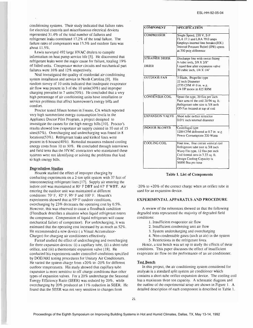
Test Bench In this project, the air conditioning system considered for
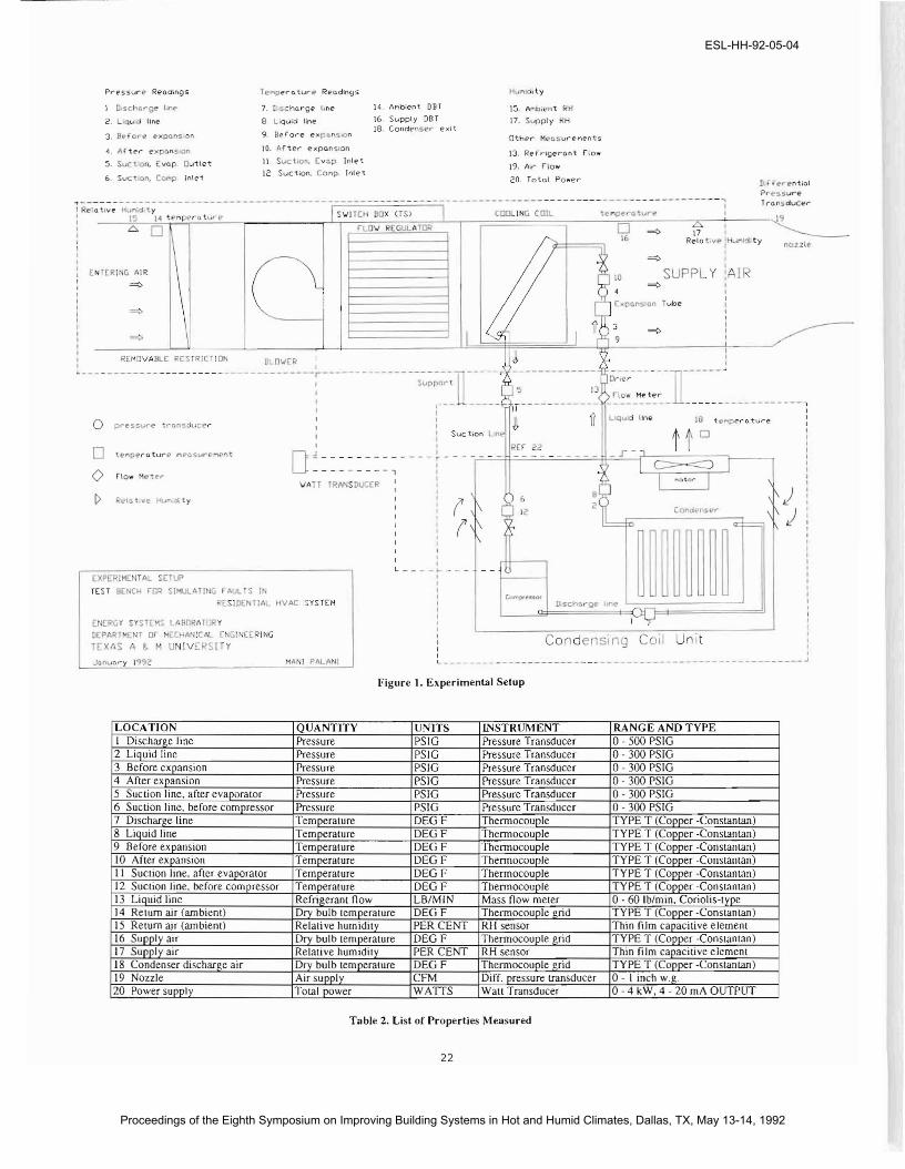
analysis is a standard split system air conditioner which contains a short-tube orifice expansion device. The cooling coil has a maximum three LOn capacity. A schematic diagram and the outline of the experimental setup are shown in Figure I. A detailed description of each component is described in Table 1.
21
ESL-HH-92-05-04
Proceedings of the Eighth Symposium on Improving Building Systems in Hot and Humid Climates, Dallas, TX, May 13-14, 1992
P,..eS5vr~ Reod:ngs Hun! .ty
1 D,scharge I: f?' 7. Dis hQrgfl' l,nE' )4. AMbien1. DDT 15. AMb,eni H
2. i l,..Il line 8 Llql"Aid line 16. Supply DBr 17. St.lpply Rn lB. Cond~!"5E'r E"xlt
3. B~ ore (>xponslon 9 R",(ore ex ClnS.On Other ME" 5urPMents
10. (lftE"r expon!tion'l. "fier €'xp nSlcn 13. Refrigerant rtow II Suct.on. [vQP Inlet5. S 'ctlon, rvon Ouilet 19, A,r flow 12 SuCiiOn. COt"'lp. Inlei
6. Suction, COr'lP intei 20. Total Po~er If e-r.niiQI P,..pssure TronsducerI R;'~ti~;-H~;;jd-~; - -- ----- ---- - - - - ----- --- - -I-S~~;(~-~X- ~;S~ ----1------- -C~~ I~~ -C-~: --- ----l-e~~:("~~~:t?- ----------~
: _--:\1~5_~I~.:-'tr":::'M:!:~T"rC;.~t::::.:.vr~"_,-_----,-S"":"'~r:;-Lr6\1~RE,":GU;;;U-;;IL'A~Tr.CRi>..LI-r::======::;----ro"l--:---Z"=---:-'----~ : .6 0 I ~ 17 I ______
: RE."IO .\If! :HL" Idity nozzle-
I NTERING AIR iriJ10 SUPPL Y :AJ: \ (\ ~~! : ~: ~ < ~ :
i~. ~-----I I I ~ ~.,.-:'~. :S
, I
t ~~~V:~~~~~~~~~~~~ ~_~~E~ ~,' --------------~~~;,o-:t-l1------. J!._5_-~-_-_-_-_~--_-~ '.~;~ ] J ~ U_~__ __ ~ ~~l_~_Mete,..__ _ I
: : \~ () line t.(-~pE'rn turl? :uquld 18o p ... essvre f""Qn5.:h.1Cl?r I '(> II : : Suct,on LIl.. tiD
o [l~========~----r----r-~~tR=E~r~-=~=-~-~-==~==~~r~--~L=~~~~~~I~----l o I>
EXPERIMLNTAL SETt.JP EST BENCH rOQ SI'1ULAT1NG rAUL S IN
RESID NTIAL HVA( -YSrEH
E [!>GY SYSTlMS L~B[l'1ATDoy
DEPART q; OJ HE..HA~:C.l -t,GI'ICCRING
TEXAS . e.. UNlv!:RSlTY
MANI PALANI
12
II
I I D.schcrgo ,,.," I I, IT I , I Co densin J Coil Unit
II IL _ I
--------------------~
Figure 1. ExperimenUiI Setup
LOCATION QUANTITY UNITS INSTRUMENT RANGE AND TYPE I Discharge line Pressure PSIG Pressure Transducer 0- 500 PSIG 2 Liquid line Pressure PSIG Pressure Transducer 0- 300 PSIG 3 Before expansion Pressure PSIG Pressure Transducer 0- 300 PSIG 4 After expansion Pressure PSIG Pressure Transducer 0- 300 PSIG 5 Suct.ion line. aft.er evaporator Pressure PSIG Pressure Transducer 0- 300 PSIG 6 Suction line. before compressor Pressure PSIG Pressure Transducer 0- 300 PSIG 7 Discharge line Temperature DEGF Thennocouple TYPE T (Copocr -Constantan) 8 Liquid line Temperature DEGF Thennocouple TYPE T (Copper -Constantan) 9 Before expansion Temperature DEGF Thcnnocouple TYPE T (Copper -Constantan) IO After expansion Temperature DEGF Thennocouple TYPE T (Copper -Constantan) II Suction line, after evaporator Temperature DEGF Thennocouple TYPE T (Copper -Constantan) 12 Suction line, before compressor Temperature DEGF Thennocouple TYPE T (Copper -Constantan) 13 Liquid line Refn.eerant flow LB/MIN Mass flow meIer o-60 Ib/min. Conolis-type 14 Return air (ambienl) Dry bulb lemperalure DEGF Thennocouple grid TYPE T (Copocr -Constantan) 15 Return air (ambienl) Relalive hUlllidily PER CENT RH sensor Thin film capacitive element 16 Supply air Dry bulb temperature DEGF Thennocouple j(rid TYPE T (Copper -Constantan) 17 Supply air Relative humidity PER CENT RH sensor Thin film capacitive element 18 Condenser discharge air Dry bulb temperature DEGF Thennocouple grid TYPE T (Copocr -Constantan) 19 Nozzle Air supply CFM Diff. pressure transducer 0- I inch w.g. 20 Power supply Total power WATTS Wall Transducer 0-4 kW, 4 - 20 rnA OlITPlIT
Table 2. List of Properties Measured
22
ESL-HH-92-05-04
Proceedings of the Eighth Symposium on Improving Building Systems in Hot and Humid Climates, Dallas, TX, May 13-14, 1992
Measurement A list of properties which were measured at the test bench is
shown in Table 2. A tOlal of 20 quantities were measured with a data acquisition system. Refrigerant pressures and temperatures were measured at six locations, as shown in Figure I. Properties measured on the air side included dry bulb temperature and relative humidity at outdoor conditions and supply conditions. Air temperature at the discharge of the condensing fan was also measured. Copper-constantan thermocouples were used to measure refrigerant and air temperatures. The refrigerant mass flow rate was measured at the liquid line before the expansion valve. A differential pressure transducer was used to measure the static pressure gain before the supply nozzle, which was converted into an air now rate. The total amount of power to run the compressor, blower and condenser fan was measured with a wall transducer.
Test Operatinl: Procedure The DOEIARI specifications indicate that steadY-Slate and
cyclic tests for Unitary Air Conditioners should be conducted in controlled environment for 30 minutes [19J. We found that the test bench reached steady-state within 4 minutes after switching on the unit. The coefficient of variation for the standard test was less than I% which was satisfactory for use in these tests. Another reason for using reduced test duration was to minimize damage to components during certain degraded tests.
De!:radation Simulation Reduction in evaporator air flow was simulated using a
plywood restriction board to cover the supply air duct. The plywood board was pre-drilled at several places to allow air flow from 100 CFM to 1000 CFM. Supply air now was varied by covering the appropriate holes.
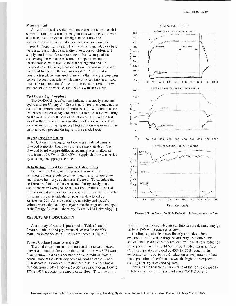
Data Reduction and Performance Calculations For each test 3 second time series data were taken for
refrigerant pressure, refrigeranttemperarure, air temperature and relative humidity, as shown in Figure 2. To calculate the performance factors, values measured during steady-state conditions were averaged for the last five minutes of the test. Refrigerant enthalpies at six locations were calculated using the refrigerant properly calculation program developed by Kartsounes[20J. Air-side enthalpy, humidity and specific volume were calculated by a psychrometric program developed at the Energy Systems Laboratory, Texas A&M University[2IJ.
RESULTS AND DISCUSSION
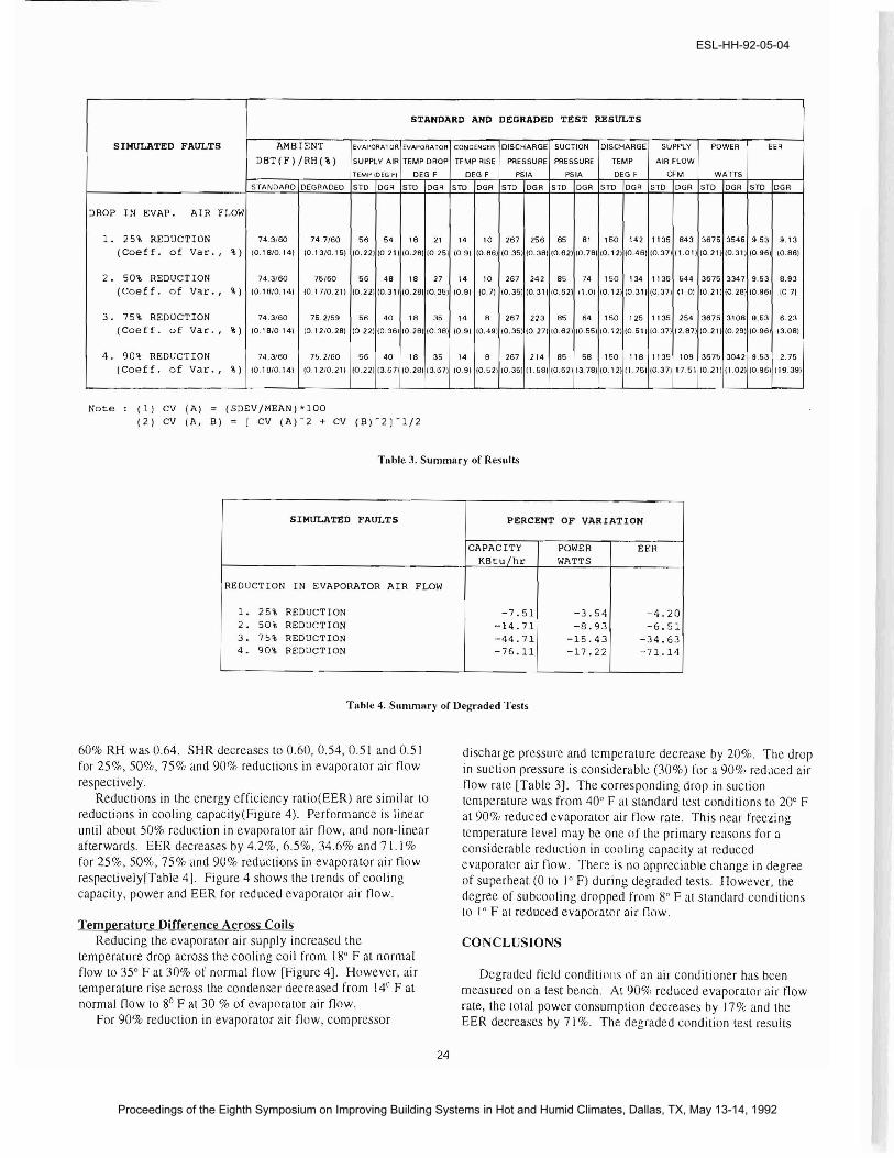
A summary of results is presented in Tables 3 and 4. Pressure-enthalpy and psychrometric charlS for the 90% reduction in evaporator air supply are shown in Figure 3.
Power, Coolin!: Capacity and EER The total power consumption for running the compressor,
blower and outdoor fan during the standard run was 3675 walls. Results shows that as evaporator air flow is reduced from a normal amount the electricity demand, cooling capacity and EER decrease. Power consumption decrease in a near linear fashion, from 3.54% at 25% reduction in evaporator air flow to 17% at 90% reduction in evaporator air flow. This may imply
STANDARD TEST REf'RIGERANT PRE:SSURE PROf'ILE
260 i------==;:::::=t====:::::::==::c--i 240
220
~200 to g 180
~ 160 ::> V)
~ 140
Cl. '" 120
100
BO
6 a L--.-~:::::::::::;:::~::::~:=:::!:.--,.-l a 100 200 300 400 500 600 700 BOO 900 1000
REf'RIGERANT TEMPERATURE PROf'ILE160 ,--__--'-''-'--'-'.;,:o.:=.:.'--.C...-,;.,;:,~~-'--'-:....::...-'-'-'.:.;..:,.::.::.,---_,
140
C'120 <.:> w o :: 100
'" 2 g 80 "::> ~ 60
40
20 ·,I--~-~--~--'.----.---.----.--~--I a 100 200 300 400 500 600 700 BOO 900 1000
AIR TEMPERATURE AND RH PROf'ILE 95 -,-----------,-------,-------,
90
V ~B5
:I:
'" r< BO'
8 co ClOT ..-.,~..,..... _I-~~---I-----_8-75
~ 270.. LU $UPf'\. Y 001 '" ~ 65
5 5 -1---,_~-=::::;:===;:::::==::;::=:::::;::::=.::::::::::!;:~~,,---1 a 100 200 300 400 500 600 700 800 900 1000
Time (Seconds)
Figure 2. Time Series for 90% Reduction in Evaporator air llow
that as utilities fix degraded air conditioners the demand may go up by 3-17% while usage goes down.
Cooling capacity decreases linearly until about 50% evaporator air now then dropped suddenly. Measurements showed that cooling capacity reduced by 7.5% at 25% reduction in evaporator air flow to 14.5% for 50% reduction in air flow. Cooling capacity decreased by 45% for 75% reduction in evaporator air flow. For 90% reduction in evaporator air flow, the degradation of performance was the highest, as expected; cooling capacity decreased by 76%.
The sensible heat ratio (SHR - ratio of the sensible capacity to total capacity) for the standard run at 75° F DBT and
23
ESL-HH-92-05-04
Proceedings of the Eighth Symposium on Improving Building Systems in Hot and Humid Climates, Dallas, TX, May 13-14, 1992
SIMULATED FAULTS
DROP IN EVAP. AIR FLOW
l. 2S% REDUCTION (Caef f. of Var"
2. SO% REDUCTION (Caeff. of Var. ,
3. 7S" REDUCTION (Caeff. of Var. ,
4. 90" REDUCTION (Caeff. of Var"
Note (1) CV (A) = (2) CV (A, B)
'I.)
'I.)
%)
")
(SDEV/MEAN)*100 = [ CV (1'1)'2 + CV (B)-2J'l/2
STANDARD AND DEGRADED TEST RESULTS
AMBIENT EVAPORATOR EVAPORATOR CO~DENSEA DISCHARGE SUCTION DISCHARGE SUPPLY POWER EER
DBT(F)/RH(%) SUPPLY AIR TEMP DROP TEMP RISE PRESSURE PRESSURE TEMP AIR FLOW
TEMP lDEG Fl DEG F DEG F PSIA PSIA DEG F CFM WAITS
STANDARD DEGRADED STD DGR STD DGR STD DGR STD DGR STD DGR srn DGR STD DGR STD DGR STD DGR
74.3/60 74.7/60 56 54 18 21 14 10 267 256 85 81 150 142 1135 843 3676 3546 9.53 9.13
(0.18/0.14} 10.13/0.16} /0.22} 10.21} 10.28} 10.251 /0.9} 10.86} (0.351 /0.381 fO.821 10.781 10.12} fO.46} (0.371 f1.01l /0.211 (0.311 fO.96} 10.86}
74.3/80 76/60 66 48 18 27 14 10 267 242 85 74 150 134 1136 644 3676 3347 9.53 8.93
(0.18/0.14} 10.17/0.211 10.221 10.311 10.281 10.351 10.91 10.71 10.351 10.311 10.62) 11.01 10.121 10.311 10.371 11.01 10.211 10.281 10.961 1071
74.3/60 76.2/59 56 40 18 35 ,4 8 267 223 85 64 150 125 1135 254 3875 3108 9.63 6.23
10.18/0141 10.12/0.281 10221 10.361 10.281 10.381 10.91 10.491 10.361 10.271 10.821 10.55} 10.121 10.61) 10.371 12.87} 10.211 10.291 10.961 13.081
74.3/60 75.2/60 56 40 18 35 14 8 267 214 85 58 150 118 1135 109 3675 3042 9.53 2.75
fO.18/0.141 (0.12/0.211 /0.221 13.671/0.281 13.67I fO.9} fO.52 } 10.351 (1.681 (0.62 113.78} 10.121(1.751 10.371 17.51 10.21 1(1.02110.96} (19.39}
REDUCTION
l. 2S% 2. SO% 3. 7S% 4. 90"
Table 3. Summary of Results
SIMULATED FAULTS PERCENT OF VARIATION
CAPACITY KBtu/hr
POWER WATTS
EER
IN EVAPORATOR AIR FLOW
REDUCTION REDUCTION REDUCTION REDUCTION
-7.S1 -14.71 -44.71 -76.11
-3.S4 -B.93
-lS.43 -17.22
-4.20 -6. Sl
-34.63 -71.14
Table 4. Summary of Deb'Taded Tests
60% RH was 0.64. SHR decreases to 0.60, 0.54, 0.51 and 0.51 for 25%,50%,75% and 90% reductions in evaporator air flow respectively.
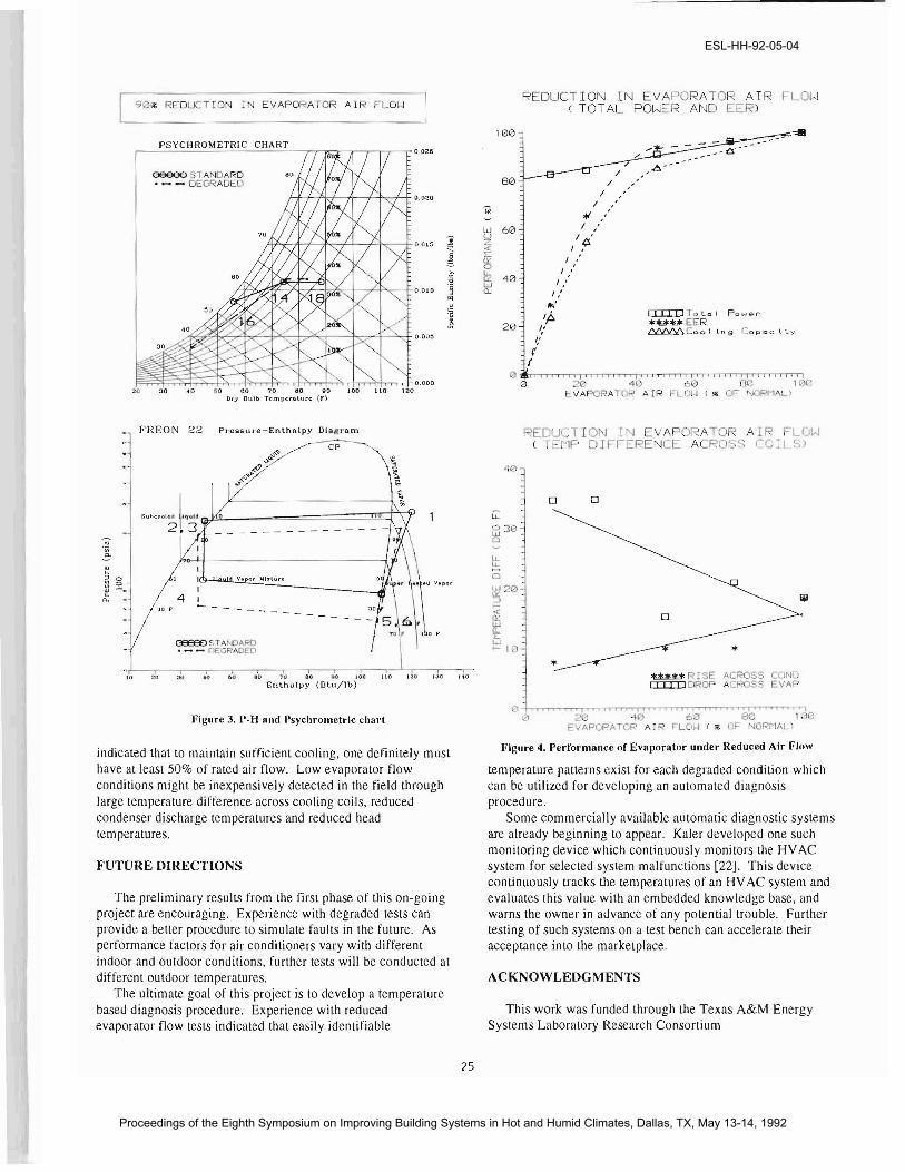
Reductions in the energy efficiency ratio(EER) are similar to reductions in cooling capacity(Figure 4). Performance is linear until about 50% reduction in evaporator air flow, and non-linear afterwards. EER decreases by 4.2%,6.5%,34.6% and 71.1 % for 25%,50%,75% and 90% reductions in evaporator air tlow respectively[Table 4]. Figure 4 shows the trends of cooling capacity, power and EER for reduced evaporator air flow.
Temperature Difference Across Coils Reducing the evaporator air sUjlply increased the
temperature drop across the cooling coil from 180 F at normal flow to 35° F at 30% of normal flow [Figure 4]. However, air temperature rise across the condenser decreased from 14° Fat normal (low to 8° F at 30 % of evaporator air flow.
For 90% reduction in evaporator air tlow, compressor
discharge pressure and temperature decrease by 20%. The drop in suction pressure is considerable (30'1'0) for a 90% reduced air flow rate lTable 3]. The corresponding drojl in suction temperature was from 40 0 F at standard test conditions to 200 F at90% reduced evaporator air flow rate. This near freezing temperature level may be one of the primary reasons for a considerable reduction in cooling capacity at reduced evaporator air flow. There is no ajljlreciable change in degree of superheat (0 to 1° F) during degraded tests. However, the degree of subcooling dropped from 80 F at standard conditions to I" F at reduced evaporator ai r flow.
CONCLUSIONS
Degraded field conditiollS of an air conditioner has been measured on a test bench. At 90% reduced evaporator air flow rate, the total power consumption decreases by 17% and the EER decreases by 71 %. The degraded condition test results
24
ESL-HH-92-05-04
Proceedings of the Eighth Symposium on Improving Building Systems in Hot and Humid Climates, Dallas, TX, May 13-14, 1992
.0
REDUCTION IN EVAPORATOR AIR FLOW 90~ REDUCTION IN EVAPORATOR AIR FLOW ( TOT AL POWER AND EER)
PSYCHROMETRIC CHART,......---'----------rr--=-r--.--,-,-,.-r 0.026
H+-I*i--fl----f---t-<d+ 0.020
N+7l-f-7I'<:--++--f-h:--l-o.O l5
~~~~~.~oooo
oeeeo STANOARD • - - DEGRADED
~
! "
>.
.~ " "' S j
30 .. 0 GO 00 70 60 90 100 110 120 D,".)' Dulb T("mIH:ro.lurc (f)
• FREON 22 Pt"cs:sul'e-Enlhatpy Diagram
CP
Suhcoollll!t jquld cJiL2 :3
d Vnpor Io1lxlur..
4 JO r
C3339:) sTAr ClARO ._- DEGRA ED
,0 20 60 &0 '0 00 ih) 100 110 i:.tO'0 Enthalpy (8tll/lb)
]1igure 3. P-H and Psychrometric chart
indicated that to maintain sufficient cooling, one definitely must have at least 50% of rated air flow. Low evaporator flow conditions might be inexpensively detected in the field through large temperature difference across cooling coils, reduced condenser discharge temperatures and reduced head tem peratures,
FUTURE DIRECTIONS
The preliminary results from the first phase of this on-going project are encouraging. Experience with degraded tests can provide a better procedure to simulate faults in the future. As performance factors for air conditioners vary with different indoor and outdoor conditions, further tests will be conducted at different outdoor temperatures,
The ultimate goal of this project is to develop a temperature based diagnosis procedure. Experience with reduced evaporator flow tests indicated that easily identifiable
__~=======l!JC:r\Y
25
100
/80 /
I , I ,
tp *' ,ld 60 ' I /
"i I '
-< lfi.... ~ 1 :
1/h1 40 1 : LU Il 1 :
III' EIII:DTo Lo I Po 1-1 6rIP. *uuEER20 I: ~Coo I Ln 9 Cop~c l Ly
1,' j'
/ , • I , , , , , f I i I f j • f \ iii' , I • iii Ii r iii .. I j, , • j " I I , • , f
2 4\) 60 80 1130 RA OF' AIR FL I..J (", OF NORMAL>
REDUCTION 11'J EVA ORATOR AIR FLOW ( TEMP DIFFERENCE ACROSS rOlLS)
o 0
tillj< R [SE ACROSS COND EIII:D DROP ACROSS EVAI'>
20 -40 '" 'iii' II II ", 'I 'i." i 'i, t 1 ,i,i ,i "1 ,i , .. ,,; i
60 80 1130 EVAPQP.ATOR AJR '-LOII ( so' OF NOPr-IAU
Figure 4. Performance of Evaporator under Reduced Air Flnw
temperature patterns exist for each degraded condition which can be utilized for developing an automated diagnosis procedure,
Some commercially available automatic diagnostic systems are already beginning to appear. Kaler developed one such monitoring device which continuously monitors the HVAC system for selected system malfunctions [22J. This device continuously tracks the temperatures of an HV AC system and evaluates this value with an embedded knowledge base, and warns the owner in advance of any potential trouble. Further testing of such systems on a test hench can accelerate their acceptance into the marketplace,
ACKNOWLEDGMENTS
This work was funded through the Texas A&M Energy Systems Laboratory Research Consortium
ESL-HH-92-05-04
Proceedings of the Eighth Symposium on Improving Building Systems in Hot and Humid Climates, Dallas, TX, May 13-14, 1992
REFERENCES;
[1] ElA, 1990. Monthly Energy Review, Energy Information Administration, June 1990.
[2] ElA, 1989. Household Energy Consumption and Expenditures 1987, DOE/EIA 032 I (87), 1989.
[3) Duffy, G.; 1991. "1991 Statistical Panorama", Air Conditioning Heating and Refrigeration News, April 1,1991.
[4] Mahoney, T. A.; 1989. "Six years of growth - it can be sustained to end of decade", Air Conditioning Heating and Refrigeration News, January 30 1989.
[5J Lewis, J. E.; 1987. "Survey of residential air-to-air heat pump service life and maintenance issues", ASHRAE Transactions, Vol. 93, Part 2, p. p. I II I - 1127.
[6J Silver, T.; 1989. "Training for the Future", Contracting Business, December 1989, p.p. 153 - 154.
[7J ACH&R News; ] 991. "Energy Prices Continue to Edge Upward", Air Conditioning Heating and Refrigeration News, April 8,1991.
[8J U.S. Public Law 100-l2-March 17, 1987, titled as "National Appliance Energy Conservation Act at' 1987", U. S. Government Documents, 1l,/87.
f9J Neal, C. L.; 1987. "Real Life Residential Air Conditioning", Refrigeration Service and Contracting, October 1987, p.p.24-27.
[IOJ Proctor, J.; 1990. "Pacific Gas and EJectric Heal Pump EffICIency and Super "Weatheriz.ation Pilot Project". Building Resources Management Corporation.
[II] Wheeler, J.; ]991. "How not to Charge Systems", Contracting Business, October, 199 J, p.p. 60-6 I.
[12] Anderson, R. T.; Neri, L.; 1990. Reliability-Centered Maintenance, Management and Engineering methods, Elsevier Applied Science Publi<.:ations.
[13] Neal, C. L.; 1986. Efficiency in Real Life Residential Air Conditioners, AEC-R-87-3, North Carolina Alternative Energy Corporation Staff Report, October 3, I9R6.
[14] Rutkowski, H.; Healy, J. H.; 1990. "Selecting Residential Air-Cooled Cooling Equipment based on Sensible and Latent Performance, ASHRAE Transactions, 1990, p.p. 851 - 855.
[15] Powell, P.; 1988. "Healthy debate or signs of confusion", Refrigeration Service and Contracting, May 1988, p.p. 18.
[16] Karger, H.; Carpenter, C. L.; 1978. "An analysis of failure patterns of 511 residential air conditioning units". ASH RAE Transactions, Vol. 84, Part 2, p.p. 462-474.
[17] Houcek, J.; and Thedford, M.; 1984. "A Research in to a New Method of Refrigeration Charging and the Effects of Improper Charging", Proceedings of the First Annual Symposium on Efficient Utilization of Energy in Residential and Commercial Buildings, Texas A&M University, August 1415,1984.
[18] Farzad, M.; O'Neal, L. D.; 1988. "An Evaluation of improper refrigerant charge on the performance of a split system air conditioner with capillary tube expansion". Energy Systems Laboratory Report. July J98R.
[19] U.S. Federal Register, 1979. "Test Procedures for Central Air Conditioners, Including Heat Pumps", Vol. 44, No. 249, December 27, J97l,/, .pp. 76700 - 76723.
[20] Kartsounes, G. T.; Erth, R. A.; 1971. "Computer Calculations of the Thermodynamic properties of Refrigerants 12,22, and 502", ASHRAE Transactions, 1971, p.p. 88-103.
[21] Katipamula, S.; 1991. "Air: Psychrometric Calculations", Version I.1, Energy Systems Laboratory, Texas A&M University.
[22] Kaler, G. M.; 1990. "Embedded expert system development for monitoring packaged HVAC equipment". ASHRAE Transactions, Vol. 96, Part 1.
[23] ASHRAE Standard 116-1983, "Methods of testing Seasonal efficiency of Unitary Air Conditioners and Heat pumps", Atlanta 1983.
BlBLlOGRAPHY
Air Conditioning and Refrigeration Institute; 1987. Refrigeration and Air conditioning, Second edition, ART Burkhardt, H. c.; 1959. Residential and Commercial Air conditioning, McGraw Hill Caristi, J. A.; 1991. Practical Air conditioning Equipment Repair, McGraw Hill. Doolin, J.; 1986. Doolin's trouble shooters bible. Doolco Publications. Geist, c.; 1982. How to solve your refrigeration and air conditioning service problems, Business News Publications. Langley, C. B.; 1986. Cooling Systems Troubleshooting Handbook, Prentice Hall. Langley, C. B.; 1980. Air conditioning and refrigeration Troubleshooting Handbook, Prentice Hall. Price, L. B., Price, T. J.; 1977. Central Heating and Air conditioning Repair Guide, TAB Books. Price, B.; Lemone W.;. How to repair Home and Auto Air conditioners, Tab Books Roman, P.; 1986. The service hot line handbook, Vol. l, II and III, Business News Publications. Russell, A.; ]977. Gelling started in heating and air conditioning service, Business News Publications. Swenson, D.; 1987. Trouble shooting and servicing air conditioning equipment, Business News Publications. Traister, E. J.; 1990. Residential Heating Ventilating and Air conditioning design and Application, Prentice Hall.
APPENDIX
Performance Parameters (ASHRA E Std. 116·1983)[23]
Air side enthalpy difference, toh (Btu/lb.) = (Enthalpy of air at 00 - Enthalpy of air at supply) ( I)
Coolin!: capacity (Btu/hr).
Cooling capacity = (60 X toh X Evaporator air now rate (CFM) ) / (Sp. vol. of air at supply conditions X (I + Sp.
Humidity)) (2)
Energy efficiency ratio (EER).
EER = Cooling capacity / Total power (3)
26
ESL-HH-92-05-04
Proceedings of the Eighth Symposium on Improving Building Systems in Hot and Humid Climates, Dallas, TX, May 13-14, 1992