Embed Size (px)
Citation preview
University of Central Florida University of Central Florida
STARS STARS
Electronic Theses and Dissertations, 2004-2019
2012
The Effect Of Magnetic Bearing On The Vibration And Friction Of The Effect Of Magnetic Bearing On The Vibration And Friction Of
A Wind Turbine A Wind Turbine
Mark Ryan Vorwaller University of Central Florida
Part of the Computer-Aided Engineering and Design Commons
Find similar works at: https://stars.library.ucf.edu/etd
University of Central Florida Libraries http://library.ucf.edu
This Masters Thesis (Open Access) is brought to you for free and open access by STARS. It has been accepted for
inclusion in Electronic Theses and Dissertations, 2004-2019 by an authorized administrator of STARS. For more
information, please contact [email protected].
STARS Citation STARS Citation Vorwaller, Mark Ryan, "The Effect Of Magnetic Bearing On The Vibration And Friction Of A Wind Turbine" (2012). Electronic Theses and Dissertations, 2004-2019. 2248. https://stars.library.ucf.edu/etd/2248
THE EFFECT OF MAGNETIC BEARING ON THE VIBRATION AND FRICTION
OF A WIND TURBINE
by
MARK RYAN VORWALLER B.S. Brigham Young University, 2011
A thesis submitted in partial fulfillment of the requirements for the degree of Master of Science
in the Department of Mechanical, Materials, and Aerospace Engineering in the College of Engineering and Computer Science
at the University of Central Florida Orlando, Florida
Summer Term 2012

ii
© 2012 Mark Ryan Vorwaller

iii
ABSTRACT
Demands for sustainable energy have resulted in increased interest in wind
turbines. Thus, despite widespread economic difficulties, global installed wind power
increased by over 20% in 2011 alone. Recently, magnetic bearing technology has been
proposed to improve wind turbine performance by mitigating vibration and reducing
frictional losses. While magnetic bearing has been shown to reduce friction in other
applications, little data has been presented to establish its effect on vibration and friction
in wind turbines. Accordingly, this study provides a functional method for experimentally
evaluating the effect of a magnetic bearing on the vibration and efficiency
characteristics of a wind turbine, along with associated results and conclusions.
The magnetic bearing under examination is a passive, concentric ring design.
Vibration levels, dominant frequency components, and efficiency results are reported for
the bearing as tested in two systems: a precision test fixture, and a small commercially
available wind turbine. Data is also presented for a geometrically equivalent ball
bearing, providing a benchmark for the magnetic bearing’s performance. The magnetic
bearing is conclusively shown to reduce frictional losses as predicted by the original
hypothesis. However, while reducing vibration in the precision test fixture, the magnetic
bearing demonstrates increased vibration in the small wind turbine. This is explained in
terms of the stiffness and damping of the passive test bearing. Thus, magnetic bearing
technology promises to improve wind turbine performance, provided that application
specific stiffness and damping characteristics are considered in the bearing design.
iv
ACKNOWLEDGMENTS
This work acknowledges the support of the Korea Research Foundation Grant
funded by the Korean Government (MEST) (KRF-2009-220-D00034) and Progress
Energy.
v
TABLE OF CONTENTS
LIST OF FIGURES ........................................................................................................ viii
LIST OF TABLES ............................................................................................................ x
CHAPTER 1: INTRODUCTION ....................................................................................... 1
CHAPTER 2: BACKGROUND ........................................................................................ 4
Rotating Machinery ...................................................................................................... 4
Wind Turbine Technology ............................................................................................ 5
Vibration Basics ........................................................................................................... 7
Magnetic Bearings ....................................................................................................... 9
CHAPTER 3: LITERATURE REVIEW ........................................................................... 11
Passive Magnetic Bearings ....................................................................................... 11
Vibration Analysis and Rotordynamics ...................................................................... 12
Wind Turbine Modeling .............................................................................................. 13
CHAPTER 4: EXPERIMENTAL METHODS .................................................................. 15
The Test Bearings ..................................................................................................... 15
Magnetic Bearing ................................................................................................... 15
Ball Bearing ............................................................................................................ 18
Experimental Testbed ................................................................................................ 18

vi
Fixture Components ............................................................................................... 20
Wind Simulation ..................................................................................................... 23
Vibration Measurements ........................................................................................ 26
Efficiency Measurements ....................................................................................... 28
Whisper 100 Wind Turbine ........................................................................................ 29
Turbine Components .............................................................................................. 29
Wind Simulation ..................................................................................................... 29
Vibration Measurement Methods ........................................................................... 31
Efficiency Measurement Methods .......................................................................... 31
CHAPTER 5: EXPERIMENTAL RESULTS ................................................................... 32
Testbed ...................................................................................................................... 32
Vibration Measurements ........................................................................................ 32
Efficiency Measurements ....................................................................................... 37
Whisper 100 Wind Turbine ........................................................................................ 39
Vibration Measurements ........................................................................................ 39
Efficiency Measurements ....................................................................................... 41
Reference Testing ..................................................................................................... 42
CHAPTER 6: ANALYTICAL MODELING ...................................................................... 45
vii
CHAPTER 7: CONCLUSIONS ...................................................................................... 48
APPENDIX A: ENGINEERING DRAWINGS ................................................................. 51
APPENDIX B: MATLAB CODE ..................................................................................... 58
LIST OF REFERENCES ............................................................................................... 62
viii
LIST OF FIGURES
Figure 1: Magnetic and Ball Bearing Test Subjects ......................................................... 2
Figure 2: Visual Representations of the Precision Test Fixture ....................................... 2
Figure 3: Commercially Available “Whisper 100” Wind Turbine ...................................... 3
Figure 4: Components of a generalized ball bearing ....................................................... 5
Figure 5: Components of Rotating Machinery Applied to Wind Turbine .......................... 5
Figure 6: Comparison of Horizontal and Vertical Axis Wind Turbines ............................. 6
Figure 7: Plane of Lateral Rotor Vibration ....................................................................... 7
Figure 8: Simple Mass, Spring, Damper System ............................................................. 8
Figure 9: Halbach Array Magnet Orientation and Arrangement .................................... 10
Figure 10: Geometry of the Passive Magnetic Bearing ................................................. 16
Figure 11: Magnetic Poles and Field Between Inner and Outer Ring Magnets ............. 16
Figure 12: Completely Assembled Magnetic Bearing in Shifted Position ...................... 17
Figure 13: Completely Assembled Magnetic Bearing Forced into Alignment ................ 17
Figure 14: Ball Bearing Used to Benchmark Magnetic Bearing Performance ............... 18
Figure 15: General Schematic of Experimental Test Set-up ......................................... 19
Figure 16: CAD Model of Fixture Assembly .................................................................. 21
Figure 17: Photo of Finished and Wired Assembly ....................................................... 21
Figure 18: Magnetic and Ball Bearing Shaft/Coupler Configuration .............................. 22
Figure 19: Reference Ball Bearing Shaft Configuration ................................................. 22
Figure 20: Single Bearing Configuration ........................................................................ 23

ix
Figure 21: Blade Orientation and Rotation Direction ..................................................... 24
Figure 22: Industrial Fan in Custom Housing ................................................................ 25
Figure 23: Wind Angle Definition ................................................................................... 25
Figure 24: Accelerometer Orientation............................................................................ 26
Figure 25: Circuit and Meters for Power Measurements ............................................... 29
Figure 26: Schematic of Wind Simulation for the Whisper 100 ..................................... 30
Figure 27: Photograph of Wind Simulation for the Whisper 100 .................................... 30
Figure 28: Magnetic and Ball Bearing Vibration Levels with No Wind Disturbance ....... 34
Figure 29: Frequency Plots for Magnetic and Ball Bearing Systems at 550 RPM ......... 35
Figure 30: Impulse Response of Magnetic and Ball Bearings to a 30 degree Gust ...... 36
Figure 31: Zoomed View of Bearing Impulse Response to a 30 degree Gust ............... 37
Figure 32: Comparison of Power Required by Ball and Magnetic Bearings .................. 39
Figure 33: Vibration Levels for Bearings on Whisper 100 Wind Turbine ....................... 41
Figure 34: Frequency Spectra for Bearings in the Whisper 100 Wind Turbine .............. 41
Figure 35: Model of an Overhung Rotating Rotor .......................................................... 45
Figure 36: Analytical Solution for an Overhung Disc Rotating at 350 RPM ................... 46
Figure 37: Analytical Solution for an Overhung Disc Rotating at 450 RPM ................... 47

x
LIST OF TABLES
Table 1: Component Details from Testbed in Figure 15 ................................................ 19
Table 2: Accelerometer Specifications .......................................................................... 27
Table 3: Signal Conditioner Specifications .................................................................... 27
Table 4: Sampling and Signal Processing Parameters ................................................. 28
Table 5: RMS Vibration Levels in X for Ball and Magnetic Bearing Systems ................ 33
Table 6: RMS Vibration Levels in Y for Ball and Magnetic Bearing Systems ................ 33
Table 7: Power Required by Motor for Ball and Magnetic Bearing-Rotor Systems ....... 38
Table 8: RMS Vibration Levels for Bearings in Whisper 100 Wind Turbine ................... 40
Table 9: Reference Testing Vibration Levels in X ......................................................... 42
Table 10: Reference Testing Vibration Levels in Y ....................................................... 42

1
CHAPTER 1: INTRODUCTION
World-wide demands for sustainable energy have resulted in increased interest
in wind turbine technology. Therefore, despite widespread economic difficulties, global
installed wind turbine power increased by over 20% in 2011 alone [1].
Magnetic bearing technology has recently been proposed to improve wind
turbine performance by mitigating vibration and reducing frictional losses. While
magnetic bearing has been shown to reduce friction in other applications, little data has
been presented to establish its effect on vibration and friction in wind turbines.
Therefore, the following study presents a functional method for experimentally
evaluating the effect of a magnetic bearing on the vibration and efficiency
characteristics of a wind turbine, along with associated results and conclusions.
The magnetic bearing under examination is a passive magnetic bearing based
on a design studied at NASA [2]. This bearing was manufactured at the University of
Central Florida by a group of mechanical engineering senior design students during the
2011-2012 academic year. Overall vibration levels, dominant frequency components,
and efficiency results are reported for this bearing, as well as for a geometrically
equivalent ball bearing, providing a benchmark for the magnetic bearing’s performance.
Figure 1 shows the magnetic and ball bearing test subjects.

2
Left: Magnetic bearing suspends rotor using magnetic repulsion Right: Ball bearing physically supports rotor
Figure 1: Magnetic and Ball Bearing Test Subjects
Experiments on these bearings were performed in two different systems: a
precision test fixture, and a small commercially available wind turbine. Figure 2 and
Figure 3 graphically illustrate the test fixture and small wind turbine respectively.
Left: Schematic of the precision test fixture Right: Photograph of the test fixture, equipped with motor and blades
Figure 2: Visual Representations of the Precision Test Fixture

3
Left: Photograph of full Whisper 100 wind turbine Right: Close-up of Whisper 100 hub and blades
Figure 3: Commercially Available “Whisper 100” Wind Turbine
Vibration and efficiency data is reported for both the magnetic and ball bearings
as tested in the test fixture and small wind turbine under various wind conditions. The
magnetic bearing is shown to reduce frictional losses as predicted by the original
hypothesis. However, while reducing vibration in the precision test fixture, the magnetic
bearing demonstrated increased vibration in the small wind turbine. This is explained in
terms of the low stiffness and damping of the passive magnetic bearing. Consequently,
it is concluded that application specific stiffness and damping characteristics must be
considered in the bearing design if magnetic bearing is to have the desired results.
Additional discussion of this study’s experimental methods, results, and
conclusions is now preceded by additional background and literary review sections,
facilitating a better understanding of the research for less-familiar readers.

4
CHAPTER 2: BACKGROUND
The following discussion provides background material related to topics
supporting a more complete understanding of this study. These topics include rotating
machinery, wind turbine technology, vibration basics, and magnetic bearing concepts.
Rotating Machinery
Rotating machinery can be generally described as any mechanical system
involving rotating parts, generally moving at high speeds. Examples include motors,
machine tools, and especially applicable to this study: turbines. Because of the rotating
parts, friction and vibration can be hazardous to proper machine operation. Common
terms associated with the components of rotating machinery include:
• Rotor – The rotating part of the machine
• Stator – The fixed part of the machine in which the rotor rotates
• Bearing – A mechanism that constrains the relative motion of moving parts
Ball Bearings are commonly used in rotating machinery to constrain the axis of rotation
of a rotor. Mechanically, this is accomplished by small balls that are allowed to roll
between concentric inner and outer tracks termed races. The general components of a
ball bearing are shown in Figure 4.

5
Figure 4: Components of a generalized ball bearing
Wind Turbine Technology
Wind turbines are an appropriate example of rotating machinery. The previously
discussed components of rotating machinery, as they apply to a common wind turbine
are identified below in Figure 5.
Figure 5: Components of Rotating Machinery Applied to Wind Turbine
Stator
Ball Bearing
Rotor (Hub and Blades attach here)
Outer Race
Inner Race
Ball
Unsealed Bearing Sealed Bearing

6
Wind turbines are used to transform wind energy into electricity. As wind action
causes the turbine blades to spin, an attached shaft provides the mechanical work
required for a generator to produce electricity. Wind turbines exist in a variety of forms,
most commonly classified into two main categories: horizontal and vertical axis wind
turbines. The wind turbines used in this study are horizontal axis wind turbines. Figure
6 visually demonstrates the difference between these two wind turbine types.
Left: Horizontal Axis Wind Turbine Right: Vertical Axis Wind Turbine
Figure 6: Comparison of Horizontal and Vertical Axis Wind Turbines
Horizontal Axis of Rotation
Vertical Axis of Rotation

7
Vibration Basics
Vibration involves mechanical oscillations about an equilibrium point, and
assuming a dynamically stable system, can continue only in the presence of a forcing
mechanism. In the case of rotating machinery, long-term forcing mechanisms are
always present at least in the form of mass unbalances in the rotor [3]. In wind turbines,
vibration is also influenced by gyroscopic effects and wind disturbances.
Wind turbine designers are concerned with vibration levels because of their effect
on turbine life. Potentially damaging peak vibration amplitudes induced by wind
disturbances must be considered. Thus, a means of analyzing and mitigating wind
turbine vibration over a wide range of operating speeds and wind conditions is essential.
The vibration studied in this research involves the orbital motion of the rotor spin
axis in the radial plane, known as lateral rotor vibration (LRV) [3]. Figure 7 identifies this
plane in which lateral rotor vibration occurs.
Figure 7: Plane of Lateral Rotor Vibration
Rotor
Plane of Lateral Rotor Vibration

8
The characteristics of a wind turbine’s LRV are significantly affected by dynamic beam
bending type deflections in the rotor. Generally, these bending type deflections are
most significant when the ratio of bearing to rotor stiffness is high [3]. Therefore, proper
selection of wind turbine bearings is essential to ensuring that vibration levels remain
within acceptable levels.
A simple single mass system helps provide a basic understanding of the
fundamental vibration concepts of stiffness and damping. Figure 8 gives an example of
such a system, including a spring with stiffness k, and damper with viscous damping
coefficient c.
Figure 8: Simple Mass, Spring, Damper System
The system’s stiffness describes the force associated with a displacement of the mass
from its equilibrium point. The system’s damping coefficient describes the force
mass
k
c
Displacement
Applied Force
9
associated with the velocity of the mass [4]. More complicated systems can also be
described in terms of their stiffness and damping characteristics.
Magnetic Bearings
Magnetic bearings use magnetic levitation forces to stabilize a rotor without any
material contact with the stator. This property not only reduces friction and wear, but
eliminates the need for bearing lubricant. Additionally, bearing stiffness and damping
properties can be designed to mitigate vibration effects [5]. Magnetic bearings can be
broadly classified based on their design and functionality into three categories. These
include active, passive, and hybrid magnetic bearings.
Active magnetic bearings use electromagnets to control the magnitude of the
magnetic suspension force. This is accomplished by supplying a time-varying current to
the electromagnets based on feedback from the rotor position. This allows active
control of the rotor. However active magnetic bearing control systems can be costly
and increase space requirements.
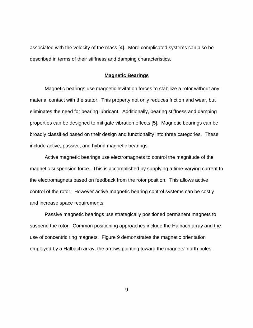
Passive magnetic bearings use strategically positioned permanent magnets to
suspend the rotor. Common positioning approaches include the Halbach array and the
use of concentric ring magnets. Figure 9 demonstrates the magnetic orientation
employed by a Halbach array, the arrows pointing toward the magnets’ north poles.

10
Figure 9: Halbach Array Magnet Orientation and Arrangement
Oriented as shown in Figure 9, the magnetic field cancels on the top side of the array,
and strengthens on the bottom side [6]. Hence, these arrays can be concentrically
wrapped around a rotor and stator such that a strong repulsive magnetic force is
created between them, creating an essentially frictionless bearing. Passive magnetic
bearings do not require the costly control equipment used in active magnetic bearings.
However, the strength of the magnetic field is fixed and cannot be actively modified to
accommodate varying operation conditions.
Hybrid magnetic bearings include bearings that employ both permanent and
electromagnets in stabilizing the rotor. In general, magnetic bearings are strong
candidates for improving the performance and efficiency of rotating machinery through
increased power output and reduced component fatigue.

11
CHAPTER 3: LITERATURE REVIEW
The following review discusses significant literature and previous work related to
the topic of passive magnetic bearings in wind turbines.
Passive Magnetic Bearings
Although the principles of magnetism have been applied to bearings for much
longer, magnetic bearings have only relatively recently been put into practical use.
Presently, dozens of companies, including Satcon Technology Corporation (Satcon),
Mechanical Technology Incorporated (MTI), and Waukesha Bearings Corporation
specialize in the commercial production of magnetic bearings. For example, Satcon has
developed magnetic bearings for refrigeration compressors under NASA and military
contracts [7]. Yet, the majority of these commercial bearings are actively controlled.
However, research on passive magnetic bearing applications has been
performed. A major example is the development of passive magnetic bearing systems
for flywheel energy storage. Ham, Burton, Lin, and Joo modeled the magnetic field of a
Halbach array passive magnetic bearing design for a flywheel [6]. Foster-Miller
Technologies studied the rotordynamics of a passive magnetic bearing system for
flywheels used in space energy storage systems [8]. NASA contributed to the research
effort by developing an experimental test rig for a concentric ring design passive
magnetic bearing [2]. Passive magnetic bearings have also found application in artificial
hearts [9].

12
Researchers have discussed the advantages and disadvantages of passive
magnetic bearings. Generally agreed strengths of passive magnetic bearings include
their near-zero friction, lower cost associated with the absence of a control system, and
overall ease of maintenance. However, research has also shown that passive magnetic
bearings can lack sufficient stiffness and damping to support high loads [10]. Therefore,
passive magnetic bearings have been suggested for use in applications such as micro
levitation systems [11].
Vibration Analysis and Rotordynamics
In general, an abundance of work has been done in the area of vibration analysis
of rotors. In addition to longstanding analytical rotor models such as the Jeffcott rotor,
finite element models have been proposed as a means of studying dynamic rotor
properties [12, 13].
Work has also been done to better understand vibration through physical testing.
Causes of rotor vibration have been shown to include misalignment, unbalance,
looseness, rubbing, resonance and component wear [14]. However, the frequency
spectra associated with these causes can be difficult to discern, as evidenced by
Ganeriwala, Patel, Hartung’s unsuccessful attempt to identify a unique frequency
spectrum associated with rotor misalignment [15]. Nonetheless, vibration patterns have
been shown to indicate design problems in rotating machinery [16].
Signal processing techniques have been discussed for optimal acquisition of
vibration signals. Liu, Liu, Sun, and Wei presented an accelerometer based design for

13
measuring vibration, including a discussion of a low-pass infinite impulse response
digital filter for denoising [17]. IRD Mechanalysis outlined the setup parameters that
must be considered in defining a fast Fourier transform (FFT) when processing a
vibration signal, including averaging type and number of averages [18].
Wind Turbine Modeling
A number of models have been developed in an effort to study the vibration of
wind turbines. These models vary in complexity and purpose, ranging from simple
representations of generalized masses, to intricate finite element models of wind turbine
geometry.
A wind turbine rotor can most simply be described by a model of a rotating
overhung disc with some degree mass unbalance. Olsson presented equations of
motion for this type of system [19]. However, this model does not describe the motion
of the wind turbine tower. A model of a wind turbine tower with a simplified mass
nacelle and rotor was studied by Nam and Yoon [20]. Coupled models including the
motion of both the wind turbine rotor and tower have been developed [21, 22].
Dozens of parameters, including blade pitch and design, can influence the
vibration experienced by a wind turbine. Models have been developed to include these
parameters, including a finite element model accounting for specific blade designs [23],
and a full turbine model considering electrical system effects [24]. Considering the large
number of parameters, data analysis methods have been studied to determine factors

14
having the most impact on wind turbine vibration. One such study found blade pitch to
have the most significant effect [25].

15
CHAPTER 4: EXPERIMENTAL METHODS
Vibration and efficiency data was experimentally obtained by two general
methods. First, data was recorded for the magnetic bearing housed in a specifically
designed test fixture. Second, data was recorded for the magnetic bearing housed in a
small commercially available wind turbine. Data from the small wind turbine offers a
means of comparison for the precision test fixture. Identical experiments were also
performed for a geometrically equivalent ball bearing traditionally used in wind turbines,
providing a benchmark for the magnetic bearing’s performance. A review of the bearing
test subjects, in addition to a detailed description of the experimental methods is given.
The Test Bearings
Two geometrically equivalent test bearings were examined by this research.
Specifically, this means that the surface areas between the inner and outer races of the
bearings are the same. In addition, their geometry allows them to fit into the same test
fixture and small wind turbine. For consistency, the bearings were coupled to the
electric motor using the same coupler.
Magnetic Bearing
The main test subject is a passive magnetic bearing. Concentric neodymium
rare earth ring magnets with axially magnetized poles generate a uniform repulsive

16
force between the inner and outer races of the bearing. Figures 10 and 11 depict the
magnetic bearing geometry and corresponding magnetic field respectively.
Figure 10: Geometry of the Passive Magnetic Bearing
Figure 11: Magnetic Poles and Field Between Inner and Outer Ring Magnets
This magnetic portion of the bearing is positioned adjacent to a single ball bearing on
one end. However, the bearing is still not axially stable, due to the tendency for the
opposite poles of the ring magnets to attract when not fixed in place. Thus, the
unrestrained bearing will prefer an orientation shifted by one ring magnet. Figure 12

17
shows the completely assembled magnetic bearing in this unrestrained shifted position,
while Figure 13 shows the bearing forced into proper alignment.
Figure 12: Completely Assembled Magnetic Bearing in Shifted Position
Figure 13: Completely Assembled Magnetic Bearing Forced into Alignment

18
Ball Bearing
The ball bearing test subject is composed of four adjacent deep-groove ball
bearings. This bearing represents the rolling-element bearings commonly found in
modern wind turbines. The bearing surface area of these four adjacent ball bearings is
geometrically equivalent to the magnetic and ball bearing surface area of the passive
magnetic bearing. Figure 14 depicts the ball bearing.
Figure 14: Ball Bearing Used to Benchmark Magnetic Bearing Performance
Experimental Testbed
A testbed was designed and assembled to experimentally measure the vibration
and efficiency characteristics of both the magnetic and ball bearing test subjects under
various wind conditions [26]. This testbed allows experiments to be performed in a
more controlled environment than that common to a larger wind turbine. A schematic of
the testbed is provided in Figure 15. Labeled items are identified in Table 1.

19
Figure 15: General Schematic of Experimental Test Set-up
Table 1: Component Details from Testbed in Figure 15
Label Item Details
A. Accelerometer ICP Accelerometer, Model #356B21
B. Bearing Housing 6061 Aluminum, Machined at University of Central Florida
C. Rotor 20 mm Diameter 1566 Steel Shaft
D. Electric Motor 50 Watt DC Motor, Rated at ~0.5 Amps
E. Signal Conditioner PCB Electronics, Model #482C05
F. BNC Cables BNC to BNC
G. USB Data Acquisition National Instruments USB9234
H. Computer Dell Inspiron 8600 with XP Pro 2002, 1.5 Ghz, 1 GB, loaded with Labview 2009
I. Fans Industrial Fan in Custom Box
J. Blades 16 inch Polyvinyl Chloride (PVC)
Angle along Floor
I
B
“Wind” C
A
DE
J
H
F
G

20
The bearing under examination is housed in an aluminum fixture, upon which is a
stud-mounted 3-axis accelerometer. The bearing supports an overhung rotor, which is
driven by an electric motor on its fixed end, and secured to three polyvinyl chloride
(PVC) blades on its free end. The blades are mounted such that the constant angular
velocity induced by the motor simulates the effect of a steady head wind. Additionally,
wind disturbances from different directions can be simulated by an appropriately placed
fan. The corresponding vibration is transferred to the accelerometer through the
bearing fixture, providing a functional means of measuring the vibration of the rotor-
bearing system. Data from the accelerometer is recorded in Labview via a signal
conditioner and a USB compatible data acquisition device.
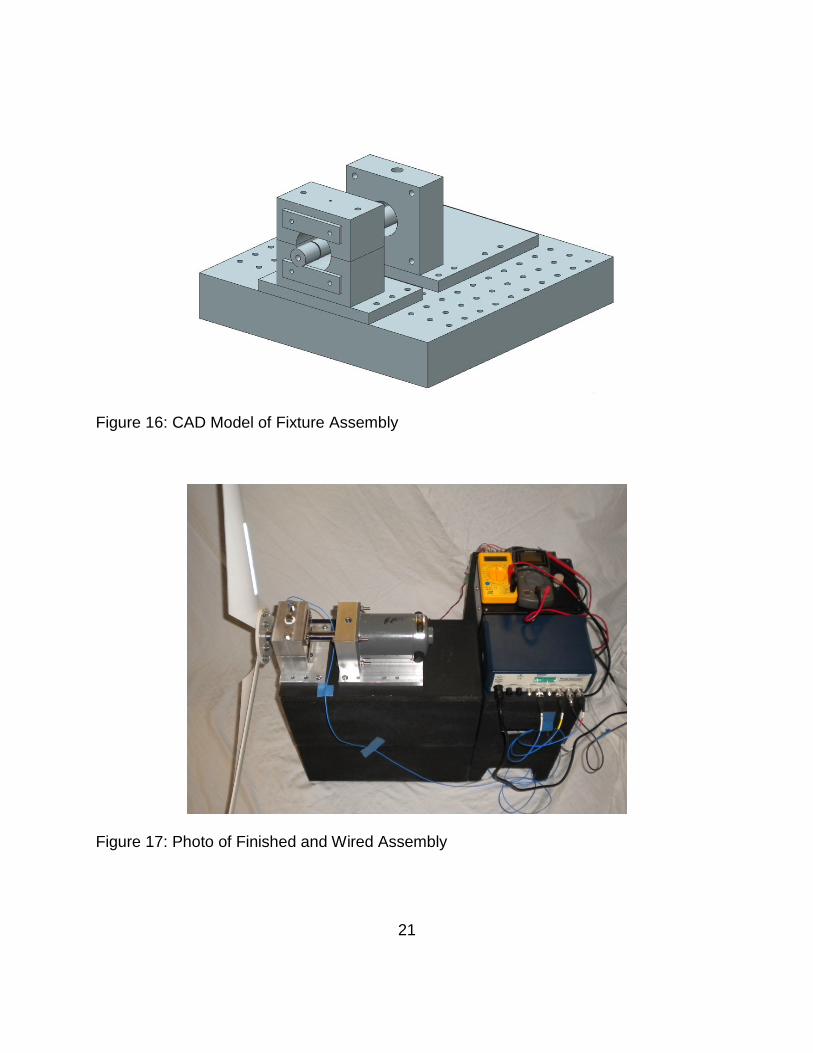
Fixture Components
The experimental testbed required the design and manufacture of a number of
custom fixture and assembly components. These components are critical for proper
motor, shaft, and bearing alignment, and include the bearing housing, motor mount, and
bearing specific shafts. Figure 16 and Figure 17 show the CAD model and finished
assembly of these particular components respectively.
21
Figure 16: CAD Model of Fixture Assembly
Figure 17: Photo of Finished and Wired Assembly

22
The components were modeled in Unigraphics NX 7.5, and manufactured at the
University of Central Florida’s machine shop. Component dimensions contributing to
proper alignment were machined to within five thousandths of an inch tolerance.
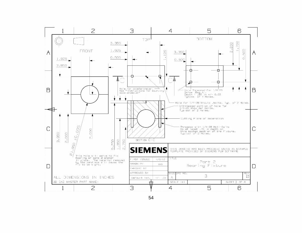
Engineering drawings for each specific part are provided in Appendix A.
Test specific shafts were machined for three general cases: magnetic bearing
and geometrically equivalent ball bearing testing, reference ball bearing testing, and
single bearing testing. Finished shafts in their appropriate configurations are shown in
Figures 18, 19, and 20.
Figure 18: Magnetic and Ball Bearing Shaft/Coupler Configuration
Figure 19: Reference Ball Bearing Shaft Configuration

23
Figure 20: Single Bearing Configuration
Each shaft is designed to properly align its associated bearing in the bearing housing,
decreasing the time required to switch between experiments. A set screw fixes the
shaft to the motor shaft.
Wind Simulation
As mentioned previously, the electric motor causes the PVC blades to rotate at a
constant rate, simulating a steady wind directed perpendicular to and towards the
forward facing plane of the blades. However, the blade positioning and direction of
motor rotation must be in agreement in order for this to be the case. Figure 21 shows
the proper blade position and associated motor rotation for the geometry of the blades
specific to this study.

24
Figure 21: Blade Orientation and Rotation Direction
Tests were performed at 350, 450, and 550 RPM. These test speeds are
justified by a calculation of an ideal tip speed ratio of five. The equation for tip speed
ratio is defined by Equation 1, where is the rotor spin speed, R is the blade radius,
and v is the wind velocity [20].
( 1 )
Assuming an approximate blade radius of one and a half feet, and an average wind of
ten miles per hour, the ideal rotor rate of rotation is 468 RPM. This falls approximately
in the center of the range of tested RPM.
In addition to measuring data for the system under the influence of a direct wind,
steady winds and wind gusts from different angles can be simulated. This is
accomplished by appropriately directing an industrial fan at the already rotating blades.
Concave side of blade faces out of the page, facing an oncoming wind
25
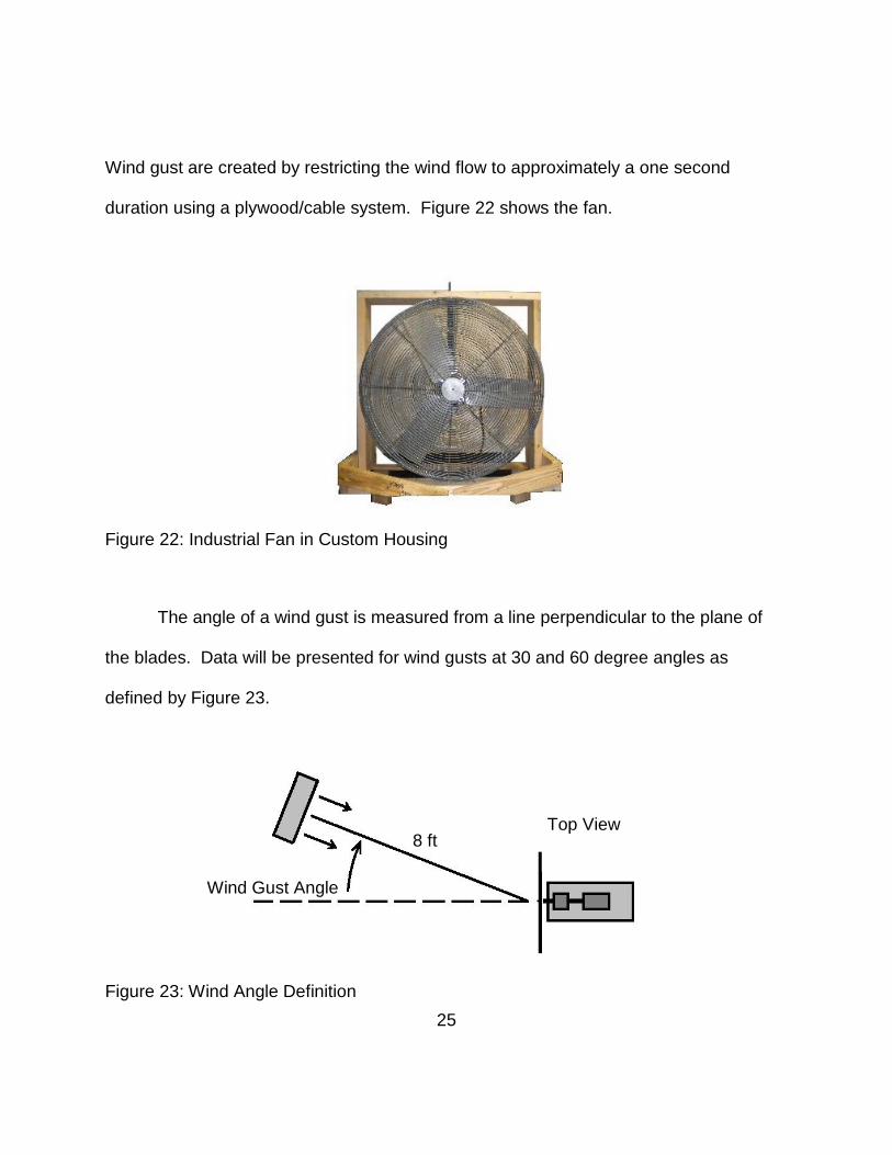
Wind gust are created by restricting the wind flow to approximately a one second
duration using a plywood/cable system. Figure 22 shows the fan.
Figure 22: Industrial Fan in Custom Housing
The angle of a wind gust is measured from a line perpendicular to the plane of
the blades. Data will be presented for wind gusts at 30 and 60 degree angles as
defined by Figure 23.
Figure 23: Wind Angle Definition
8 ft
Top View
Wind Gust Angle

26
Vibration Measurements
Measuring the vibration of the rotor-bearing system required the use of several
commercially available electronic devices, including a 3-axis accelerometer, a signal
conditioner, a USB compatible data acquisition device, and a Labview equipped
computer. The following sections provide additional detail regarding these components
of the measurement system.
The 3-axis accelerometer was mounted as to readily provide lateral rotor
vibration data. Figure 24 defines the Cartesian directions associated with the lateral
and axial components of the rotor-bearing system vibration. As lateral vibration is the
primary interest of this research, axial vibration data is not presented.
Figure 24: Accelerometer Orientation
The accelerometer requires a constant current excitation source to function
properly. This constant current is provided by connecting the accelerometer to a signal
Accelerometer

27
conditioner. Table 2 and Table 3 provide important specifications related to the
accelerometer and associated signal conditioner. These specifications provide an
understanding of the limitations of the measurement system, and thus effect the
interpretation of this research’s experimental results.
Table 2: Accelerometer Specifications
Specification English Units SI Units
Sensitivity 10.2 mV/g 1.040 mV/m/s2
Frequency Range (Y and Z) 2 to 10,000 Hz 2 to 10,000 Hz
Frequency Range (X) 2 to 7,000 Hz 2 to 7,000 Hz
Table 3: Signal Conditioner Specifications
Specification English Units SI Units
Constant Current Excitation 4 mA 4 mA
Voltage Gain 1:1 1:1
Output Range +/- 10 V +/- 10 V
Additionally, data acquired by an accelerometer is effected by the acquisition
process and subsequent signal processing. Thus, to maintain consistency, sampling
parameters and signal processing techniques were maintained between experiments on
the test fixture as described in Table 4:

28
Table 4: Sampling and Signal Processing Parameters
Parameter Value or Description
Number of Samples 40,000
Sampling Rate 10,000 Hz
Number of Loops 5
Filter Type Low Pass Infinite Impulse Response
Cut-off Frequency 50 Hz
Filter Topology Butterworth, order 5
FFT Type Magnitude - Peak
FFT Averaging 5 Linearly Weighted Averages
Efficiency Measurements
The efficiency of a bearing was defined in terms of the electrical power required
to drive the corresponding rotor under given conditions. The equation for power is given
in Equation 2.
P = IV ( 2 )
By this equation, power (P) is equal to the product of current (I) and voltage (V).
Measurements were taken for these values using meters integrated into the circuitry
between the motor and its power supply. This circuit is shown in Figure 25.

29
Figure 25: Circuit and Meters for Power Measurements
Whisper 100 Wind Turbine
The Whisper 100 wind turbine was used to experimentally test the magnetic and
ball bearings in a true-life wind turbine system, providing a method of analyzing and
validating the performance of the bearings in the precision test fixture.
Turbine Components
The Whisper 100 wind turbine is a self-contained small wind turbine. The
horizontal axis of rotor rotation stands five feet high and the blades have a three and a
half foot radius. The Whisper 100 was shown previously in Figure 3.
Wind Simulation
The wind simulation method used for the Whisper 100 wind turbine was slightly
different than that used for the test fixture. Because the Whisper 100 is free to rotate
about a vertical axis, it will naturally align itself with the direction of an oncoming wind.

30
For this reason, the influence of off-axis wind disturbances was not studied for the
Whisper 100 wind turbine. An additional fan is used to account for the larger size of the
turbine. Figure 26 and Figure 27 show the experimental setup associated with the
Whisper 100.
Figure 26: Schematic of Wind Simulation for the Whisper 100
Figure 27: Photograph of Wind Simulation for the Whisper 100
12 ft
31
Vibration Measurement Methods
The same 3-axis accelerometer was used as in the precision test fixture
experiments, oriented in the same manner. However, it was mounted using a wax
provided with the accelerometer. This was done as to not permanently alter the
Whisper 100 wind turbine.
Efficiency Measurement Methods
Efficiency measurements were not taken in the same manner as performed on
the precision test fixture. RPM values were recorded for the magnetic and ball bearings
in the Whisper 100 turbine subject to the same direct wind, giving an indication of
bearing friction effects.

32
CHAPTER 5: EXPERIMENTAL RESULTS
Overall vibration levels, dominant frequency components, and efficiency results
are reported for the precision testbed and small wind turbine experiments. The effects
of steady and impulse type wind disturbances are presented for the precision testbed.
These results are discussed in terms of the original hypothesis that magnetic bearing
will improve wind turbine performance by mitigating vibration induced by wind
disturbances and reducing frictional losses.
Testbed
RMS vibration levels in the lateral directions, dominant frequency components,
and efficiency results are reported for the magnetic and ball bearings as tested on the
precision testbed. The effects of steady and impulse type wind disturbances are also
reported.
Vibration Measurements
RMS vibration levels and dominant frequency components are reported for the
magnetic and ball bearing systems. Table 5 and Table 6 present RMS vibration levels
in terms of the horizontal and vertical components of lateral rotor vibration, denoted by
X and Y, respectively. RPM values indicate the undisturbed speed of the motor.

33
Table 5: RMS Vibration Levels in X for Ball and Magnetic Bearing Systems
X Direction RMS Vibration (g) RPM Wind Ball Bearing Magnetic Bearing % Decrease 350 Direct Wind 0.0126 0.0112 11.4 30o Steady 0.0159 0.0148 7.0 60o Steady 0.0130 0.0116 10.7 450 Direct Wind 0.0139 0.0134 3.4 30o Steady 0.0406 0.0309 24.0 60o Steady 0.0203 0.0186 8.3 550 Direct Wind 0.0153 0.0143 6.9 30o Steady 0.0315 0.0275 12.9 60o Steady 0.0225 0.0200 11.0
Table 6: RMS Vibration Levels in Y for Ball and Magnetic Bearing Systems
Y Direction RMS Vibration (g) RPM Wind Ball Bearing Magnetic Bearing % Decrease 350 Direct Wind 0.0088 0.0075 14.6 30o Steady 0.0101 0.0095 5.9 60o Steady 0.0090 0.0081 9.9 450 Direct Wind 0.0096 0.0079 17.6 30o Steady 0.0155 0.0107 30.8 60o Steady 0.0108 0.0094 13.6 550 Direct Wind 0.0102 0.0093 9.1 30o Steady 0.0196 0.0167 14.9 60o Steady 0.0117 0.0102 12.7
The data in Table 5 and Table 6 supports the original hypothesis that magnetic bearing
will improve wind turbine performance by mitigating vibration. Experimentally, the
magnetic bearing reduced horizontal and vertical components of lateral rotor vibration in
each case tested. The following observations can be made from the data:
34
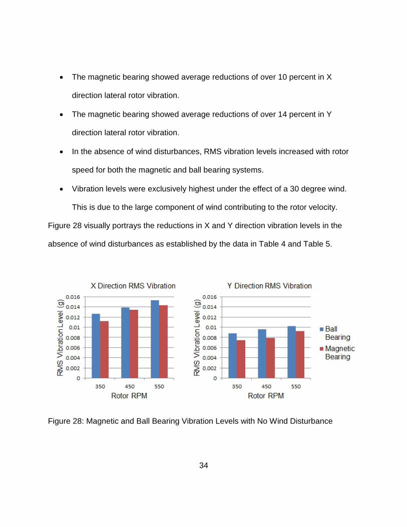
• The magnetic bearing showed average reductions of over 10 percent in X
direction lateral rotor vibration.
• The magnetic bearing showed average reductions of over 14 percent in Y
direction lateral rotor vibration.
• In the absence of wind disturbances, RMS vibration levels increased with rotor
speed for both the magnetic and ball bearing systems.
• Vibration levels were exclusively highest under the effect of a 30 degree wind.
This is due to the large component of wind contributing to the rotor velocity.
Figure 28 visually portrays the reductions in X and Y direction vibration levels in the
absence of wind disturbances as established by the data in Table 4 and Table 5.
Figure 28: Magnetic and Ball Bearing Vibration Levels with No Wind Disturbance

35
Frequency data was also recorded for the magnetic and ball bearing systems.
The resulting frequency plots confirm the trend in the RMS vibration level data, showing
clear reductions in the dominant frequency components for the magnetic bearing
system. Figure 29 demonstrates these reductions for the system running at 550 RPM
without wind disturbances.
Figure 29: Frequency Plots for Magnetic and Ball Bearing Systems at 550 RPM
36
Figure 29 shows significant reductions in the dominant frequency components for lateral
rotor vibration at 550 RPM. The frequency plots show the largest frequency component
at three times the rotor spin speed, corresponding to the three turbine blades.
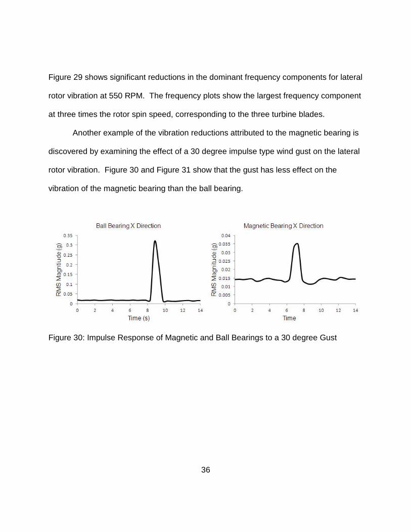
Another example of the vibration reductions attributed to the magnetic bearing is
discovered by examining the effect of a 30 degree impulse type wind gust on the lateral
rotor vibration. Figure 30 and Figure 31 show that the gust has less effect on the
vibration of the magnetic bearing than the ball bearing.
Figure 30: Impulse Response of Magnetic and Ball Bearings to a 30 degree Gust

37
Figure 31: Zoomed View of Bearing Impulse Response to a 30 degree Gust
As expected, Figure 30 and Figure 31 show higher initial RMS values for the ball
bearing, followed by a higher response to the wind gust. This gives added support to
the suggestion that magnetic bearing will improve wind turbine performance by
mitigating vibration due to wind disturbances.
Efficiency Measurements
Table 7 reports the power required by the motor to drive the ball bearing and
magnetic bearing-rotor systems. This data was recorded at the same time as the
previously reported vibration data.
38
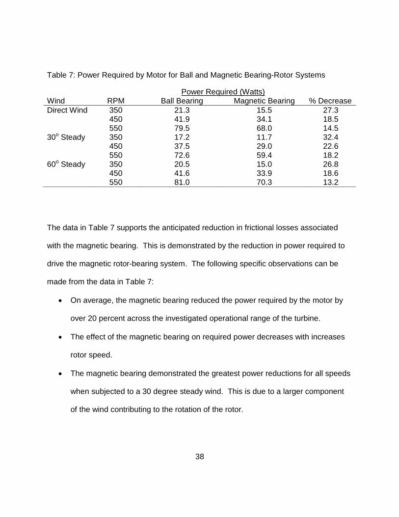
Table 7: Power Required by Motor for Ball and Magnetic Bearing-Rotor Systems
Power Required (Watts) Wind RPM Ball Bearing Magnetic Bearing % Decrease Direct Wind 350 21.3 15.5 27.3 450 41.9 34.1 18.5 550 79.5 68.0 14.5 30o Steady 350 17.2 11.7 32.4 450 37.5 29.0 22.6 550 72.6 59.4 18.2 60o Steady 350 20.5 15.0 26.8 450 41.6 33.9 18.6 550 81.0 70.3 13.2
The data in Table 7 supports the anticipated reduction in frictional losses associated
with the magnetic bearing. This is demonstrated by the reduction in power required to
drive the magnetic rotor-bearing system. The following specific observations can be
made from the data in Table 7:
• On average, the magnetic bearing reduced the power required by the motor by
over 20 percent across the investigated operational range of the turbine.
• The effect of the magnetic bearing on required power decreases with increases
rotor speed.
• The magnetic bearing demonstrated the greatest power reductions for all speeds
when subjected to a 30 degree steady wind. This is due to a larger component
of the wind contributing to the rotation of the rotor.

39
Figure 32 graphically portrays the decrease in power required to drive the magnetic
bearing under the tested wind conditions.
Figure 32: Comparison of Power Required by Ball and Magnetic Bearings
Whisper 100 Wind Turbine
Experimental RMS lateral rotor vibration and efficiency measurements are
reported for the Whisper 100 wind turbine.
Vibration Measurements
Table 8 presents vibration levels for the magnetic and ball bearings in the
Whisper 100 wind turbine under the effect of a direct wind.

40
Table 8: RMS Vibration Levels for Bearings in Whisper 100 Wind Turbine
RMS Vibration (g) Bearing Turbine RPM X Direction Y Direction Ball Bearing 250 0.029 0.032 Magnetic Bearing 270 0.060 0.081 Percent Increase 8 % 109.4 % 154.4 %
The data in Table 8 appears to oppose the hypothesis that the magnetic bearing will
mitigate vibration. This is in contrast to the results demonstrated on the precision test
fixture. Additionally, the following observations can be made from the data in Table 8:
• Although the magnetic bearing allowed the wind turbine to run at a slightly higher
speed, RMS vibration levels in X were over twice as large as those experienced
with the ball bearing.
• RMS vibration levels for the magnetic bearing in Y were over two and a half
times as large as those experienced with the ball bearing.
• RMS vibration levels were higher in Y than for X for both bearings, in contrast to
the results found on the test fixture.
Figure 33 demonstrates the substantial increase in vibration experienced by the wind
turbine with the magnetic bearing graphically.

41
Figure 33: Vibration Levels for Bearings on Whisper 100 Wind Turbine
Figure 34 confirms that the vibration is higher in the magnetic bearing system
based on the frequency spectra of the vibration in the Whisper 100.
Figure 34: Frequency Spectra for Bearings in the Whisper 100 Wind Turbine
Efficiency Measurements
Power measurements were not taken on the Whisper 100 turbine, due to
substantial coverage in previous research. However, it is noted that despite the higher
42
vibration level, the Whisper 100 ran at a higher speed with the passive magnetic
bearing, confirming the expected reduction of frictional losses.
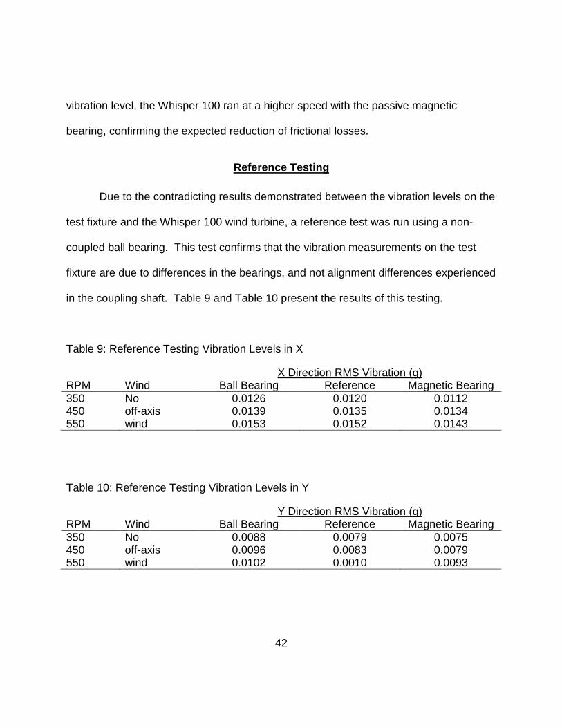
Reference Testing
Due to the contradicting results demonstrated between the vibration levels on the
test fixture and the Whisper 100 wind turbine, a reference test was run using a non-
coupled ball bearing. This test confirms that the vibration measurements on the test
fixture are due to differences in the bearings, and not alignment differences experienced
in the coupling shaft. Table 9 and Table 10 present the results of this testing.
Table 9: Reference Testing Vibration Levels in X
X Direction RMS Vibration (g) RPM Wind Ball Bearing Reference Magnetic Bearing 350 No 0.0126 0.0120 0.0112 450 off-axis 0.0139 0.0135 0.0134 550 wind 0.0153 0.0152 0.0143
Table 10: Reference Testing Vibration Levels in Y
Y Direction RMS Vibration (g) RPM Wind Ball Bearing Reference Magnetic Bearing 350 No 0.0088 0.0079 0.0075 450 off-axis 0.0096 0.0083 0.0079 550 wind 0.0102 0.0010 0.0093

43
Table 9 and Table 10 provide strong evidence that the RMS values measured on the
test fixture are accurate reflections of the test bearings, and not due to misalignment in
the shaft coupling. The reference bearing is on a continuous shaft, and thus would be
expected to have better alignment than the coupled ball bearing. This is confirmed by
the lower vibration levels in Tables 9 and 10. However, the coupled magnetic bearing
still exhibits even lower vibration than both the coupled and uncoupled ball bearings,
confirming the initial result that the magnetic bearing outperforms the ball bearing on the
precision test fixture.
These apparently contradictory results are explained in terms of the passive
magnetic bearing’s stiffness and damping characteristics. Passive magnetic bearings
have been shown to generally have much lower stiffness and damping than traditional
ball bearings [2, 7]. Thus, in lightly loaded systems where deflections are very small,
such as the precision test fixture, the lower stiffness of the magnetic bearing offers less
resistance to the deflections, thereby transferring less vibration to the bearing fixture.
The deflections are small enough that the bearing’s low damping does not become a
factor. This is supported by studies showing that relaxing bearing stiffness through
critical speeds can reduce machine structure vibration [7]. On the other hand, in
systems supporting higher loads where deflections may be large, such as the Whisper
100 wind turbine, the low damping provides insufficient energy dissipation. This allows
the deflections, and thus vibration, to become much larger than in the ball bearing
system. Therefore, magnetic bearings must be designed with wind turbine specific
44
stiffness and damping properties if they are to have the intended effect [10]. This can
be accomplished by modifying the number of magnets, changing the gap distance
between inner and outer races, or utilizing a hybrid or active magnetic bearing design.
Another discrepancy between the precision test fixture and the small wind turbine
involved the relative magnitudes of the X and Y components of lateral rotor vibration. In
the test fixture, the X component of vibration was shown to be consistently larger than
the Y component. However, the opposite was shown to be true in the Whisper 100
wind turbine. This is explained in terms of the structural characteristics of the two
systems. The precision test fixture does not allow motion associated with a wind turbine
tower, and is subsequently more constrained in the vertical (Y) direction. Nam and
Yoon showed tower and rotor vibration to be coupled [20].

45
CHAPTER 6: ANALYTICAL MODELING
A simple analytical model of a rotating overhung disc was used to assess the
experimental results presented in this study. A graphical depiction of this four degree of
freedom model is shown in Figure 35.
Figure 35: Model of an Overhung Rotating Rotor
The equations of motion for this model are provided in Equation 3. Parameter
definitions and a derivation of Equation 3 are given by Olsson [19].
( 3 )
z
x
y
Where:
φ = Angle about x
θ = Angle about y

46
Equation 3 is a system of four second-order ordinary differential equations in time.
However, it can be manipulated into a system of eight first-order ordinary differential
equations in time by using a state space approach. First-order derivatives are defined
as state variables. Then, second order derivatives can be defined as first order
derivatives of these state variables. This system of eight equations is well suited for
solution by Matlab’s ode45 function. The Matlab code for this system and solution
method is found in Appendix C. Figure 36 and Figure 37 show the analytical solutions
for an overhung disc rotating at 350 and 450 RPM respectively.
Figure 36: Analytical Solution for an Overhung Disc Rotating at 350 RPM

47
Figure 37: Analytical Solution for an Overhung Disc Rotating at 450 RPM
Although differences are noted due to simplifying assumptions, the analytical
model supports the experimental results. In agreement with this study, the model
shows increasing vibration levels with RPM. Additionally, the model shows a dominant
frequency component corresponding to one times the rotor spin speed. A three times
spin speed component would be seen if individual blade masses were included in the
model. In contrast to the experimental results, the model shows symmetric X and Y
direction vibration levels of the same magnitude. Harmonic frequency components in
the experimental frequency spectra also differ. This is explained in terms of bearing
and fixture specific characteristics not taken into account by the analytical model.
However, the model provides a baseline supporting the experimental results.

48
CHAPTER 7: CONCLUSIONS
A functional method for experimentally evaluating the effect of magnetic bearing
on wind turbine vibration and friction was successfully developed, and associated
results were presented for magnetic and ball bearing test subjects in a precision test
fixture and small wind turbine. Clear friction reductions, and vibration reductions
dependent on application specific bearing design, support the suggested use and
further study of magnetic bearing technology to improve wind turbine performance.
The data presented by this study decisively supports the expected reductions in
frictional losses associated with magnetic bearing. Compared to the traditional ball
bearing, the magnetic bearing was shown to significantly reduce friction in both the test
fixture and the small wind turbine. These results support the proposition that passive
magnetic bearings will make wind energy more economical.
Additionally, vibration results showed that magnetic bearing will mitigate wind
turbine vibration, provided that application specific stiffness and damping characteristics
are considered in the bearing design. For instance, while vibration due to wind
disturbances was reduced by the passive magnetic bearing in the precision test fixture,
vibration was shown to be higher for the magnetic bearing in the Whisper 100 wind
turbine. These results were explained in terms of the passive magnetic bearing’s
stiffness and damping properties. Therefore, rather than discounting the possible
vibration-related advantages of magnetic bearing, these results suggest the importance
of carefully designing magnetic bearing properties for their specific application. Thus,
49
turbine-specific magnetic bearing designs are recommended to ensure the intended
vibration mitigation. Suggested design variables to be considered include rotor loading,
bearing air-gap distance, number, size and type of magnets. These findings also
strongly advise the investigation of hybrid or active magnetic bearing designs, where
bearing stiffness and damping properties can be actively controlled.
Several other fascinating directions for future work are suggested by the findings
from this study. These demonstrate the value of the precision testbed to other vibration
related studies. The following examples are noted:
• A study of the effects of magnetic bearing on the vibration and friction of a wind
turbine using an active magnetic bearing test subject.
• Development of analytical stiffness and damping models for passive and active
magnetic bearing designs.
• Establishment of vibration models considering bearing stiffness, damping, and
loading relationships.
• Development of structural monitoring techniques using vibration data from the
precision testbed. For example, blade deflects could be inflicted and studied.
• A study of the effect of blade design on vibration using the precision testbed.
Magnetic bearing has been conclusively shown to reduce frictional losses in wind
turbine applications, and to reduce vibration provided application specific bearing
designs are considered. These findings support the suggested use of magnetic bearing

50
technology in the effort to improve wind turbine performance, and provide motivation for
continued research in the area of magnetic bearing design for wind turbines. Such
research will allow wind power to continue to advance as an increasingly competitive
and reliable form of alternative energy.

51
APPENDIX A: ENGINEERING DRAWINGS

52

53
54
3 3

55
4 4

56
5 5

57
6 6

58
APPENDIX B: MATLAB CODE

59
%Function defining the equations of motion for the rotor system function arrayofderivatives = SystemRotor2(t,y) m = 0.875; Jp = 46.055; Jd = 23.027; k1 = 5375000; k2 = 1238000; k3 = 379900; spin = 36.65; u = 0.05; %Load Data from txt file created by C++ Program % load rotorData.txt; % A = [1:8]; % A = rotorData(:,1); % A = single(A); %Create variables from loaded Data % m = A(1); % Jp = A(2); % Jd = A(3); % k1 = A(4); % k2 = A(5); % k3 = A(6); % spin = A(7); % u = A(8); %State-space representation of equations of motion arrayofderivatives(1) = y(2); arrayofderivatives(2) = (m*u*spin^2*cos(spin*t)+k2*y(7)-k3*y(1))/m; arrayofderivatives(3) = y(4); arrayofderivatives(4) = (m*u*spin^2*sin(spin*t)-k3*y(3)-k2*y(5))/m; arrayofderivatives(5) = y(6); arrayofderivatives(6) = (spin*-Jp*y(8)-k2*y(3)-k1*y(5))/Jd; arrayofderivatives(7) = y(8); arrayofderivatives(8) = (spin*Jp*y(6)+k2*y(1)-k1*y(7))/Jd; %Ensure arrayofderivatives is a column vector for use by ode45 arrayofderivatives = arrayofderivatives(:) ;

60
%Set up and call ode45 y0 = [0 ; 0 ; 0 ; 0 ; 0 ; 0 ; 0 ; 0]; endtime = 100; tspan = [0, endtime]; [t,y] = ode45('SystemRotor2', tspan, y0); % Plot of the solution whitebg('white') subplot(4,1,1), plot(t,y(:,1),'black') xlabel('Time') h = get(gca,'xlabel'); set(h,'FontName','Arial','FontSize',12) ylabel('Displacement (in)') i = get(gca,'ylabel'); set(i,'FontName','Arial','FontSize',12) title('X Direction Vibration of Overhung Rotor System') j = get(gca,'title'); set(j,'FontName','Arial','FontSize',12) % Plot of the solution subplot(4,1,2), plot(t,y(:,3),'black') xlabel('Time') k = get(gca,'xlabel'); set(k,'FontName','Arial','FontSize',12) ylabel('Displacement (in)') l = get(gca,'ylabel'); set(l,'FontName','Arial','FontSize',12) title('Y Direction Vibration of Overhung Rotor System') m = get(gca,'title'); set(m,'FontName','Arial','FontSize',12) % Next power of 2 from length of y1 y1 = y(:,1); %Change to do FFT on another solution {EX: y(:,3) is y disp} L = length(y(:,1)); %Change to do FFT on another solution Fs = L/endtime; NFFT = 2^nextpow2(L); Y = fft(y1,NFFT)/L; f = Fs/2*linspace(0,1,NFFT/2+1); % Next power of 2 from length of y3 y3 = y(:,3); %Change to do FFT on another solution {EX: y(:,3) is y disp} L3 = length(y(:,3)); %Change to do FFT on another solution

61
Fs3 = L3/endtime; NFFT3 = 2^nextpow2(L3); Y3 = fft(y3,NFFT3)/L; f3 = Fs3/2*linspace(0,1,NFFT3/2+1); % Plot single-sided amplitude spectrum for X subplot(4,1,3), plot(f,2*abs(Y(1:NFFT/2+1)),'black') title('X Direction Vibration Frequency Spectrum') n = get(gca,'title'); set(n,'FontName','Arial','FontSize',12) xlabel('Frequency (Hz)') o = get(gca,'xlabel'); set(o,'FontName','Arial','FontSize',12) ylabel('Amplitude') p = get(gca,'ylabel'); set(p,'FontName','Arial','FontSize',12) % Plot single-sided amplitude spectrum for Y subplot(4,1,4), plot(f3,2*abs(Y3(1:NFFT3/2+1)),'black') title('Y Direction Vibration Frequency Spectrum') q = get(gca,'title'); set(q,'FontName','Arial','FontSize',12) xlabel('Frequency (Hz)') r = get(gca,'xlabel'); set(r,'FontName','Arial','FontSize',12) ylabel('Amplitude') s = get(gca,'ylabel'); set(s,'FontName','Arial','FontSize',12) set(gcf,'Color','white') %Compute RMS Values columnVectorX = y(:,1); columnVectorY = y(:,3); rowVectorX = columnVectorX'; rowVectorY = columnVectorY'; sizeX = size(columnVectorX) sizeY = size(columnVectorY) numValues = sizeX(1) squareX = rowVectorX*columnVectorX squareY = rowVectorY*columnVectorY rmsX = sqrt(squareX/numValues) rmsY = sqrt(squareY/numValues)

62
LIST OF REFERENCES
[1] Sawyer, S., & Rave, K. (2012, March). Global wind report: annual market update
2011. Retrieved from http://www.gwec.net
[2] NASA. (2008). Permanent magnetic bearing for spacecraft applications. Cleveland,
OH: Morales, W., Fusaro, R., & Kascak, A.
[3] Adams, M. (2001). Rotating machinery vibration. New York: Marcel Dekker
Incorporated.
[4] Rao, S. (2004). Mechanical vibrations. Upper Saddle River, NJ: Pearson Education,
Incorporated.
[5] Genta,G. (2005). Dynamics of rotating systems. New York, NY: Springer Science
and Business Media Incorporated.
[6] Ham, C., Burton, M., Lin, K., & Joo, Y. (2011). Proceedings from the 15th World
Multi-Conference on Systemics, Cybernetics, and Informatics: Development of a
passive magnetic bearing system for a flywheel energy storage.
[7] Gibson, T. (2000). Magnetic bearings: an update. Retrieved from
http://motionsystemdesign.com
[8] Foster-Miller Technologies. (2004). Rotordynamics of a passive magnetic bearing
system. Albany, NY: Chen, H., Walter, T., Wheeler, T., & Lee, N.
[9] Shen, J., Tseng, K., Vilathgamuwa, D., & Chan, W. (2000). A novel compact PMSM
with magnetic bearing for artificial heart application. IEEE Transactions on
Industrial Applications, 36(4), 1061-1068.

63
[10] Hawkings, L. (2012). Magnetic bearings. Retrieved from http://www.calnetix.com
[11] Schweitzer, G., & Maslen, E. (Eds). (2009). Magnetic bearings. New York, NY:
Springer Publishing.
[12] ElMadany, M., & Abduljabbar, Z. (2004). Proceedings from the Mansoura 4th
International Conference: On the dynamic analysis of rotor-bearing systems
using finite elements.
[13] Xiang, J., Chen, D., Chen, X. & He, Z. (2009). A novel wavelet-based finite element
method in the analysis of rotor bearing systems. Finite Elements in Analysis and
Design, 45, 908-916.
[14] IRD Mechanalysis, Inc. (1994). Introduction to vibration technology. Columbus, OH:
Shreve, D.
[15] Spectraquest, Incorporated. (n.d.). The truth behind misalignment vibration spectra
of rotating machinery. Richmond, VA: Ganeriwala, S., Patel, S., & Hartung, A.
[16] U.S. Department of Energy. (1996). Vibration testing (Contract No. DE-AC36-
84CH0093). Retrieved from http://www.nrel.gov
[17] Liu, R., Liu, M., Sun, X., & Wei, Y. (2008). Proceedings from the 2008 International
Conference on Embedded Software and Systems: Signal processing and
accelerometer based design for portable small displacement measurement
device. Washington, DC: IEEE.
[18] IRD Mechanalysis, Incorporated. (1995). Signal processing for effective vibration
analysis. Columbus, OH: Shreve, D.
64
[19] Olsson, F. (2006). Rotordynamic model of a fibre refinery in BEAST. (Thesis).
Retrieved from Lulea University of Technology Publication Database.
[20] Nam, Y., & Yoon, T. (2008). Proceedings from 10th International Conference on
Control, Automation, Robotics, and Vision: Estimation of a nacelle dynamic
motion of a wind turbine. Hanoi, Vietnam: IEEE.
[21] Hansen, M. (2010). Wind turbine dynamics and aeroelasticity [Course Notes].
Retrieved by email.
[22] Kessentini, S., Choura, S., Najar, F., & Francher, M. (2010). Modeling and
dynamics of a horizontal wind turbine. Journal of Vibration and Control, 16(13),
2001-2021.
[23] Liu, C., Jiang, D., & Chen, J. (2010). Proceedings form the 2010 World Non-grid-
connected Wind Power and Energy Conference: Vibration characteristics of a
wind turbine rotor using modal and harmonic analysis of FEM.
[24] Fadaeinedjad, R., Moallem, M., & Moschopoulos, G. (2008). Simulation of a wind
turbine with doubly fed induction by FAST and Simulink. IEEE Transactions on
Energy Conversion, 23(2), 690-700.
[25] Kusiak, A., & Zhang, Z. (2010). Analysis of wind turbine vibrations based on
SCADA data. Journal of Solar Energy Engineering, 132, 1-12.
[26] Vorwaller, M., Lin, K., Gou, J., Ham, C., & Joo, Y. (2012). Testbed for a wind
turbine with magnetic bearing. Advanced Materials Research, 512, 657-660.