Embed Size (px)
Citation preview
Abstract—Recently, reliability is one of the serious
requirements of electronic systems. The numbers of system
failures, repair cost, guarantee and etc are estimated by
reliability prediction. In this paper, the reliability of a switching
power supply, which is used for personal computers, evaluates.
It will show that electrolytic capacitors, used in input and
output filters, play a significant role on the computer’s power
supply’s life time. Ambient temperature, derating, and
capacitance effect on the failure rate will discuss. The remedies
are recommended for more life time.
Index Terms—Electrolytic capacitor, reliability, SMPS, PC.
I. INTRODUCTION
Switch Mode Power Supplies (SMPSs) are used in
Personal Computers (PCs), because of their high efficiency
and low volume and weight. SMPSs are used in all PCs for
convert the voltage to different levels and establish it against
input voltage and load variations [1].
The efficiency of joinery SMPSs, are used in PCs, is about
70% and all the power consumption of PC produced by
subsystem. So they are the most critical point of PCs from
reliability lookout and almost 90% of PC failures belong to
their SMPSs.
Lifetime and failure rate of a system can be predicted by
reliability calculations. Recently, reliability became to a
prevalent issue in power electronic systems. The effect of
transformer leakage inductance on SMPSs reliability is
discussed in [2]. The effect of equivalent series resistance of
capacitors on the reliability of SMPSs is presented in [3].
Reliability modification of power electronic converter for full
cell and photovoltaic application are discussed [4]-[6].
Dissertation of operating mode (continuous and
discontinuous modes) with aim of reliability, for SMPSs,
presented in [7] and using a single integrated power module
(IPM) instead of paralleling power electronic devices are
given in [8].
The method of reliability calculation, for a PC’s SMPS, is
presented, and the most critical points are introduced in
previous work [9]. It is shown that electrolytic capacitors
have a major role in the SMPS’s reliability.
AC voltage is converted to DC via a rectifier and a bulk
capacitor in the input stage of a SMPS. At the output stage of
SMPSs, usually, an LC filter, which is composed of an
inductor and a capacitor, is placed to filter out the ripple
voltage and noises caused by the switching devices. So, it has
Manuscript received January 5, 2013; revised May 18, 2013. This work was supported in part by Damavand Branch, Islamic Azad
University.
The Authors are with Damavand Branch, Islamic Azad University, Damavand, Tehran, Iran (e-mail: [email protected]).
to be used some high capacitive capacitors in the input and
output stages of SMPSs. Due to its large capacity and low
cost, electrolytic capacitors with the abilities of energy
storage and voltage regulation are used for filters of SMPSs.
In order to reduce the size and cost, as well as to improve the
performance of the SMPSs, different ratings of electrolytic
capacitors are used in the design and construction process.
The performance of the electrolytic capacitor is highly
affected by its operation conditions such as voltage, current,
frequency, and temperature [10]-[12]. If the electrolytic
capacitor is used as a part of the LC filter, it must present a
low-impedance path for the ac current and act as a constant
voltage source to the load. Unfortunately, an aged electrolytic
capacitor will not be able to provide a low-impedance path
for the ac current and cannot be treated as a constant voltage
source anymore. Therefore, it will cause the increment of the
output ripple voltage. Eventually, it will cause the converter
to fail in the output voltage regulation, or it may even damage
the converter itself. On the other hand, among the power
stage components of switching-mode power converters,
electrolytic capacitors are most affected by the aging effect
[13], [14]. Consequently, the electrolytic capacitor plays a
very important role for the SMPS’s quality and reliability,
and it is very important to predict the expected lifetime of the
electrolytic capacitor.
The influence of electrolytic capacitors parameters on
SMPS’s reliability is given in this paper. In the reliability
point of view voltage derating, temperature, amount of
capacitance and their paralleling effect are some important
parameters which they are investigated here.
All of reliability definitions and discussions are according
to MIL-HDBK-217F [15], in this paper.
II. DEFINITION OF RELIABILITY
The probability of proper function of a system after a time
interval is referred to as its reliability.
It is dependent on the type and quality of the parts and
materials used in the device, tension of each part endures and
the ambient conditions which the devices are working. The
failure rate in most of the electronic systems is constant,
represented by λ; the reliability is expressed by:
tetR )( (1)
The mathematical mean of R (t) occurs at:
1t
(2)
Which is the amount of time that should elapses until the
first failure occurs. This is called the Mean Time to Failure
The Effect of Electrolytic Capacitors on SMPS’s Failure
Rate
B. Abdi, R. Ghasemi, and S. M. M. Mirtalaei, Member, IACSIT
International Journal of Machine Learning and Computing, Vol. 3, No. 3, June 2013
300DOI: 10.7763/IJMLC.2013.V3.326
(MTTF). The mean time to repair (MTTR) of the system is
negligible compared to MTTF, so the mean time between
failures (MTBF) of a system is expressed as:
1 MTTFMTTRMTBF (3)
The total rate of the system failure is the sum of the failure
rates of all parts of the system:
N
n
partsystem
1
(4)
Hence, the reliability of the system will be the product of
all the system components’ reliabilities [9]:
system partR R (5)
III. RELIABILITY OF PC’S SMPSS COMPONENTS
A case study power supply, used in PC, converts input
voltage (220V, 50Hz or 115V, 60Hz) to ±12, +5 and
+3.3VDC. It also regulates them against input voltage and
load variations. The output voltages can provide up to 300
watts continuously and up to 600 watts instantaneously. The
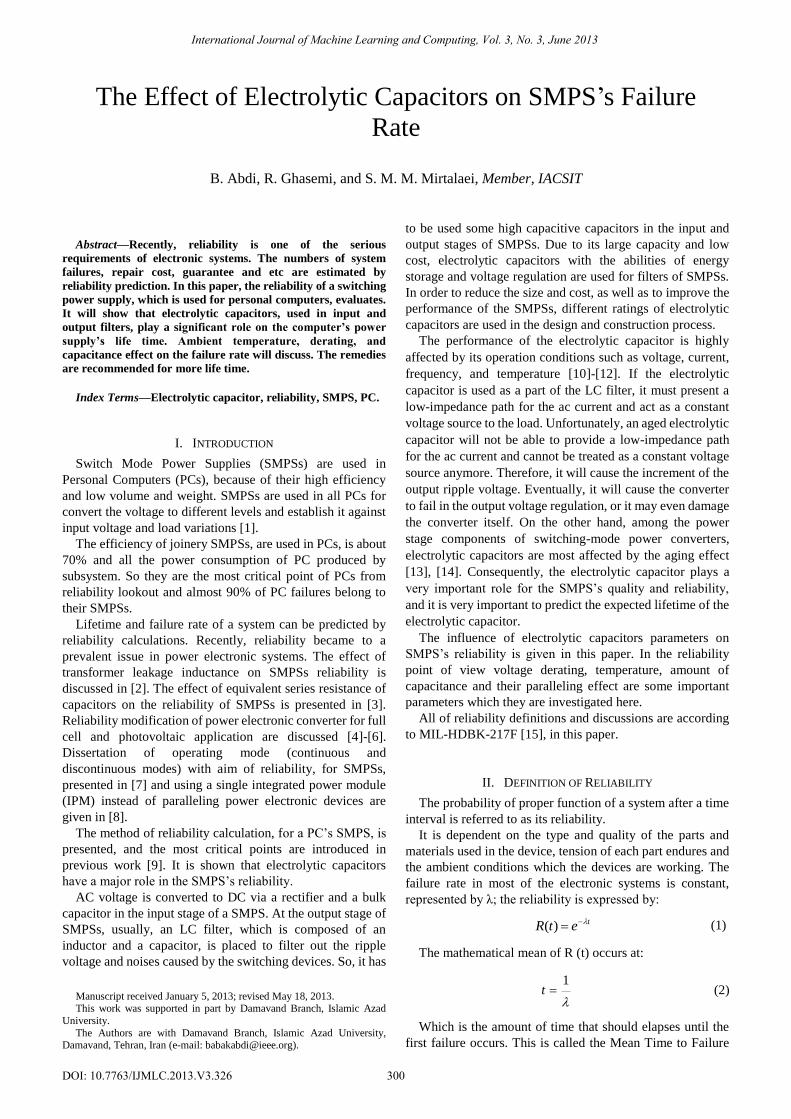
case study power supply and its block diagram are shown in
Fig. 1 and Fig. 2. They basically utilize from half bridge
topology which stabilizes output voltages using Pulse Width
Modulation (PWM) control [1].
Fig. 1. PC’s switch mode power supply.
In reliability calculation, there is a basic failure rate for
each device. It is shown by λb. The basic failure rate is
affected by quality factor of each device (πQ), stress factor (πs)
which is the ratio of operational to nominal parameters (like
voltage and current), temperature factor (πT) and working
ambient or environmental factor (πE). There are another
factors belong to specific devices. For example capacitance
factor (πc) belongs to capacitors.
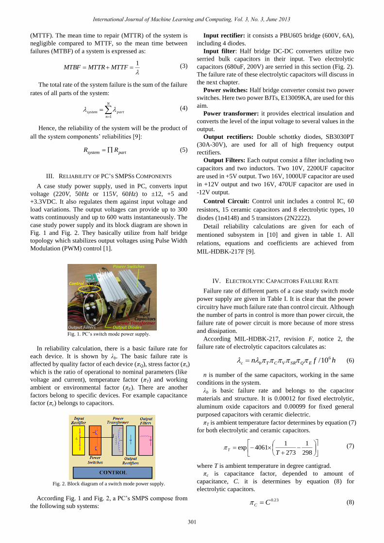
Fig. 2. Block diagram of a switch mode power supply.
According Fig. 1 and Fig. 2, a PC’s SMPS compose from
the following sub systems:
Input rectifier: it consists a PBU605 bridge (600V, 6A),
including 4 diodes.
Input filter: Half bridge DC-DC converters utilize two
serried bulk capacitors in their input. Two electrolytic
capacitors (680uF, 200V) are serried in this section (Fig. 2).
The failure rate of these electrolytic capacitors will discuss in
the next chapter.
Power switches: Half bridge converter consist two power
switches. Here two power BJTs, E13009KA, are used for this
aim.
Power transformer: it provides electrical insulation and
converts the level of the input voltage to several values in the
output.
Output rectifiers: Double schottky diodes, SB3030PT
(30A-30V), are used for all of high frequency output
rectifiers.
Output Filters: Each output consist a filter including two
capacitors and two inductors. Two 10V, 2200UF capacitor
are used in +5V output. Two 16V, 1000UF capacitor are used
in +12V output and two 16V, 470UF capacitor are used in
-12V output.
Control Circuit: Control unit includes a control IC, 60
resistors, 15 ceramic capacitors and 8 electrolytic types, 10
diodes (1n4148) and 5 transistors (2N2222).
Detail reliability calculations are given for each of
mentioned subsystem in [10] and given in table 1. All
relations, equations and coefficients are achieved from
MIL-HDBK-217F [9].
IV. ELECTROLYTIC CAPACITORS FAILURE RATE
Failure rate of different parts of a case study switch mode
power supply are given in Table I. It is clear that the power
circuitry have much failure rate than control circuit. Although
the number of parts in control is more than power circuit, the
failure rate of power circuit is more because of more stress
and dissipation.
According MIL-HDBK-217, revision F, notice 2, the
failure rate of electrolytic capacitors calculates as:
hfn EQSRVCTbc
610/ (6)
n is number of the same capacitors, working in the same
conditions in the system.
λb is basic failure rate and belongs to the capacitor
materials and structure. It is 0.00012 for fixed electrolytic,
aluminum oxide capacitors and 0.00099 for fixed general
purposed capacitors with ceramic dielectric.
πT is ambient temperature factor determines by equation (7)
for both electrolytic and ceramic capacitors.
298
1
273
14061exp
TT
(7)
πc is capacitance factor, depended to amount of
capacitance, C. it is determines by equation (8) for
electrolytic capacitors.
23.0CC (8)
International Journal of Machine Learning and Computing, Vol. 3, No. 3, June 2013
301
where T is ambient temperature in degree cantigrad.
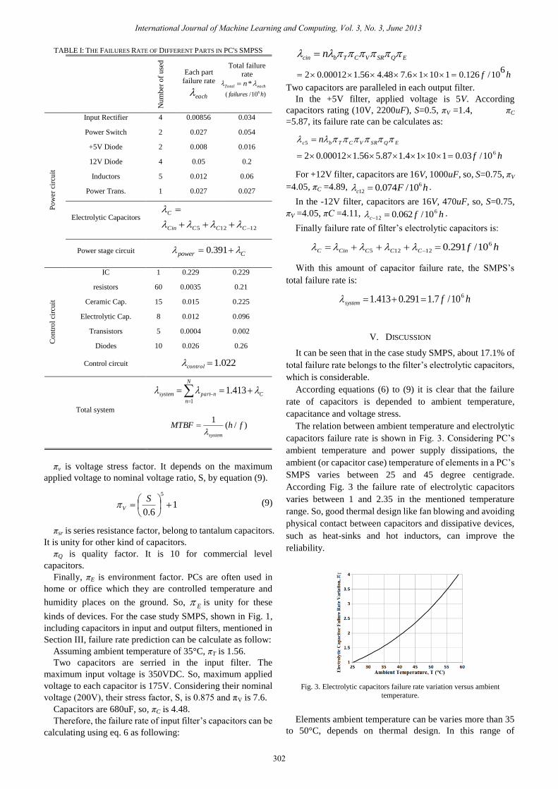
TABLE I: THE FAILURES RATE OF DIFFERENT PARTS IN PC'S SMPSS
Total failure
rate
eachTotal n *
)10/( 6 hfailures
Each part
failure rate
each
Nu
mber
of
use
d
0.034 0.00856 4 Input Rectifier
Po
wer
cir
cuit
0.054 0.027 2 Power Switch
0.016 0.008 2 +5V Diode
0.2 0.05 4 12V Diode
0.06 0.012 5 Inductors
0.027 0.027 1 Power Trans.
12125
CCCCin
C
Electrolytic Capacitors
0.391power C Power stage circuit
0.229 0.229 1 IC
Con
tro
l ci
rcuit
0.21 0.0035 60 resistors
0.225 0.015 15 Ceramic Cap.
0.096 0.012 8 Electrolytic Cap.
0.002 0.0004 5 Transistors
0.26 0.026 10 Diodes
022.1control Control circuit
C
N
n
npartsystem
413.11
Total system
)/(1
fhMTBFsystem
πv is voltage stress factor. It depends on the maximum
applied voltage to nominal voltage ratio, S, by equation (9).
16.0
5
SV (9)
πsr is series resistance factor, belong to tantalum capacitors.
It is unity for other kind of capacitors.
πQ is quality factor. It is 10 for commercial level
capacitors.
Finally, πE is environment factor. PCs are often used in
home or office which they are controlled temperature and
humidity places on the ground. So, E is unity for these
kinds of devices. For the case study SMPS, shown in Fig. 1,
including capacitors in input and output filters, mentioned in
Section III, failure rate prediction can be calculate as follow:
Assuming ambient temperature of 35°C, πT is 1.56.
Two capacitors are serried in the input filter. The
maximum input voltage is 350VDC. So, maximum applied
voltage to each capacitor is 175V. Considering their nominal
voltage (200V), their stress factor, S, is 0.875 and πV is 7.6.
Capacitors are 680uF, so, πC is 4.48.
Therefore, the failure rate of input filter’s capacitors can be
calculating using eq. 6 as following:
62 0.00012 1.56 4.48 7.6 1 10 1 0.126 /10
cin b T C V SR Q E
f h
n
Two capacitors are paralleled in each output filter.
In the +5V filter, applied voltage is 5V. According
capacitors rating (10V, 2200uF), S=0.5, πV =1.4, πC
=5.87, its failure rate can be calculates as:
hf
n EQSRVCTbc
6
5
10/03.011014.187.556.100012.02
For +12V filter, capacitors are 16V, 1000uF, so, S=0.75, πV
=4.05, πC =4.89, 6
12 0.074 /10c F h .
In the -12V filter, capacitors are 16V, 470uF, so, S=0.75,
πV =4.05, πC =4.11, hfc
6
12 10/062.0 .
Finally failure rate of filter’s electrolytic capacitors is:
hfCCCCinC
6
12125 10/291.0
With this amount of capacitor failure rate, the SMPS’s
total failure rate is:
hfsystem
610/7.1291.0413.1
V. DISCUSSION
It can be seen that in the case study SMPS, about 17.1% of
total failure rate belongs to the filter’s electrolytic capacitors,
which is considerable.
According equations (6) to (9) it is clear that the failure
rate of capacitors is depended to ambient temperature,
capacitance and voltage stress.
The relation between ambient temperature and electrolytic
capacitors failure rate is shown in Fig. 3. Considering PC’s
ambient temperature and power supply dissipations, the
ambient (or capacitor case) temperature of elements in a PC’s
SMPS varies between 25 and 45 degree centigrade.
According Fig. 3 the failure rate of electrolytic capacitors
varies between 1 and 2.35 in the mentioned temperature
range. So, good thermal design like fan blowing and avoiding
physical contact between capacitors and dissipative devices,
such as heat-sinks and hot inductors, can improve the
reliability.
Fig. 3. Electrolytic capacitors failure rate variation versus ambient
temperature.
Elements ambient temperature can be varies more than 35
to 50°C, depends on thermal design. In this range of
International Journal of Machine Learning and Computing, Vol. 3, No. 3, June 2013
302
temperature variation πT varies from 1.56 to 2.9 which causes
electrolytic capacitors failure rate variations from 0.291 to
o.56. This variation of capacitors failure rate causes variation
of total system failure rate from 1.7 to 1.97 failures per
million hours which means 15.8% more failures. Briefly,
15°C of temperature variations in electrolytic capacitors
ambient, which arises from thermal design, causes 15.8% less
life time.
The second effective parameter in capacitor’s life time is
capacitance factor. SMPS designer uses two or more
paralleled small electrolytic capacitor instead off one bulk
capacitor for equivalent series resistance (ESR) and
equivalent series inductance (ESL) minimization. But it will
be shown here that it can be decrease life time of the
converter. ESR and ESL can be developed by paralleling one
some nano-farad ceramic or other kind of capacitors which
almost effective less on the reliability.
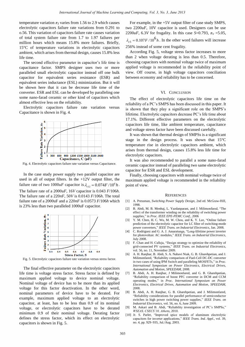
Electrolytic capacitors failure rate variation versus
Capacitance is shown in Fig. 4.
Fig. 4. Electrolytic capacitors failure rate variation versus Capacitance.
In the case study power supply two parallel capacitor are
used in all of output filters. In the +12V output filter, the
failure rate of two 1000uF capacitor is 6
12 0.074 /10c F h .
The failure rate of a 2000uF, 16V capacitor is 0.043 F/106h.
The failure rate of a 220nF, 50V is 0.0143 F/106h. The total
failure rate of a 2000uF and a 220nF is 0.0573 F/106h which
is 23% less than two paralleled 1000uF capacitor.
Fig. 5. Electrolytic capacitors failure rate variation versus stress factor.
The final effective parameter on the electrolytic capacitors
life time is voltage stress factor. Stress factor is defined by
maximum applied voltage to device nominal voltage.
Nominal voltage of device has to be more than its applied
voltage for this factor deactivation. In the other word,
nominal parameters of device have to be derated. For
example, maximum applied voltage to an electrolytic
capacitor, at least, has to be less than 0.9 of its nominal
voltage, or electrolytic capacitors have to be derated
minimum 0.9 of their nominal voltage. Derating factor
defines the stress factor, which its effect on electrolytic
capacitors is shown in Fig. 5.
For example, in the +5V output filter of case study SMPS,
two 2200uF, 10V capacitor is used. Designers can be use
2200uF, 6.3V for frugality. In this case S=0.793, πV =5.05,
5
60.107 /10c F h . In the other word failures will increase
256% instead of some cent frugality.
According Fig. 5, voltage stress factor increases to more
than 2 when voltage derating is less than 0.5. Therefore,
choosing capacitors with nominal voltage twice of maximum
applied voltage is recommended in the reliability point of
view. Off course, in high voltage capacitors conciliation
between economy and reliability has to be concerned.
VI. CONCLUSION
The effect of electrolytic capacitors life time on the
reliability of a PC’s SMPS has been discussed in this paper. It
is shown that they play a significant role on the SMPS’s
lifetime. Electrolytic capacitors decrease PC’s life time about
17.1%. Different effective parameters on the electrolytic
capacitors life time, like ambient temperature, capacitance
and voltage stress factor have been discussed carefully.
It was shown that thermal design of SMPSs is a significant
stage in the design process. It was shown that 15°C
temperature rise in electrolytic capacitors ambient, which
arises from thermal design, causes 15.8% less life time for
electrolytic capacitors.
It was also recommended to parallel a some nano-farad
ceramic capacitor instead of paralleling two same electrolytic
capacitor for ESR and ESL development.
Finally, choosing capacitors with nominal voltage twice of
maximum applied voltage is recommended in the reliability
point of view.
REFERENCES
[1] A. Pressman, Switching Power Supply Design, 2nd ed. McGraw-Hill,
1998.
[2] B. Abdi, M. B. Menhaj, L. Yazdanparast, and J. Milimonfared, “The effect of the transformer winding on the reliability of switching power
supplies,” in Proc. IEEE EPE-PEMC Conf., 2006
[3] Y. M. Chen, H. C. Wu, M. W. Chou, and K. Y. Lee, “Online failure prediction of the electrolytic capacitor for LC filter of switching-mode
power converters,” IEEE Trans. on Industrial Electronics, Jan. 2008.
[4] C. Rodriguez and G. A. J. Amaratunga, “Long-lifetime power inverter for photovoltaic AC modules,” IEEE Trans. on Industrial Electronics,
July 2008.
[5] F. Chan and H. Calleja, “Design strategy to optimize the reliability of grid-connected PV systems,” IEEE Trans. on Industrial Electronics,
vol. 56, no. 11, November 2009.
[6] A. H. Ranjbar, B. Abdi, S. A. Nabavi Niak, G. B. Gharehpetian, and J. Milimonfared, “Reliability comparison of Fuel-Cell DC-DC converter
in two cases of using IPM Switch and paralleling MOSFETs,” in Proc.
International Symposium on Power Electronics, Electrical Drives, Automation and Motion, SPEEDAM, 2008.
[7] B. Abdi, A. H. Ranjbar, J Milimonfared, and G. B. Gharehpetian, “Reliability comparison of boost PFC converter in DCM and CCM
operating modes,” in Proc. International Symposium on Power
Electronics, Electrical Drives, Automation and Motion, SPEEDAM, 2008.
[8] B. Abdi, A. H. Ranjbar, G. B. Gharehpetian, and J. Milimonfared,
“Reliability considerations for parallel performance of semiconductor
switches in high power switching power supplies,” IEEE Trans. on
Industrial Electronics, vol. 56, no. 6, June 2009.
[9] M. Askari and B. Abdi, “Reliability investigation of PC’s SMPSs,” WSEAS, CSECS’10, Athens, 2010.
[10] Jr. S. Parler, “Improved spice models of aluminum electrolytic
capacitors for inverter applications,” IEEE Trans. Ind. Appl., vol. 39, no. 4, pp. 929–935, Jul./Aug. 2003.
International Journal of Machine Learning and Computing, Vol. 3, No. 3, June 2013
303
[11] M. Gasperi, “Life prediction modeling of bus capacitors in AC variable
frequency drives,” IEEE Trans. Ind. Appl., vol. 41, no. 6, Nov./Dec.
2005.
[12] T.-Y. Chang, X. Wang, D. Evans, S. Roberson, and J. Zheng,
“Characterization of tantalum oxide-ruthenium oxide hybrid
capacitor,” IEEE Trans. Ind. Electron., vol. 51, no. 6, pp. 1313–1317, Dec. 2004.
[13] G. Chen, R. Burgos, Z. Liang, F. Lacaux, F. Wang, J. Wyk, W.
Odendaal, and D. Boroyevich, “Reliability-oriented design considerations for highpower converter modules,” in Proc. IEEE
Power Electron. Spec. Conf., 2004.
[14] P. Venet, H. Darnand, and G. Grellet, “Detection of faults of filter capacitors in a converter. Application to predictive maintenance,” in
Proc. IEEE Int. Telecommun. Energy Conf., 1993.
[15] “Reliability Prediction of Electronic Equipment,” MIL-HDBK-217F, notice 2, 1995.
Babak Abdi was born in Tehran in 1976. He received his M.S. and Ph.D. degree in electrical
engineering in 2005 and 2009 from Amirkabir
University of Technology (Tehran Polytechnic), Tehran, Iran, respectively. He is currently a member
of IEEE and a faculty member of Damavand branch,
Islamic Azad University, Tehran, Iran. His research interests include power electronics, application of
reliability in power electronics, Electromagnetic
Interferences (EMI), and electrical machines and drives.
Reza Ghasemi
was born in Tehran, Iran in 1979. He
received his B.Sc. degree
in Electrical engineering
from Semnan University in 2000. He received the M.Sc. and the Ph.D.
degree
in control engineering
from Amirkabir University of Technology, Tehran,
Iran
in 2004 and 2009, respectively. His research interests include large-Scale Systems, adaptive
control, robust control, nonlinear control, and
intelligent systems.
Reza Ghasemi joined the Department of Electrical Engineering, Damavand Branch, Islamic Azad
University, Tehran, Iran, where he is currently an assistant professor of
electrical engineering.
Sayyed Mohammad Mehdi Mirtalaei
was born in
Shahreza-Isfahan, Iran in 1983. He received his B.S.
degree in electrical engineering from Isfan University
of Technology, Iran in 2005. He received his M.S. and
Ph.D.
in electrical engineering from Amirkabir
University of Technology, Tehran, Iran in 2007 and
2012 respectively. His research interest are
power electronics, EMI/EMC and numerical method in
electromagnetic.
Author’s formal
photo
International Journal of Machine Learning and Computing, Vol. 3, No. 3, June 2013
304