Embed Size (px)
Citation preview
Procedia CIRP 4 ( 2012 ) 157 – 160
2212-8271 © 2012 The Authors. Published by Elsevier B.V. Selection and/or peer-review under responsibility of Prof. Eiji Shamotodoi: 10.1016/j.procir.2012.10.028
3rd CIRP Conference on Process Machine Interactions (3rd PMI)
The Effect of Cutting Parameters on Cutting Force During Turning Multiphase Microalloyed Steel
V.Sivaramana*, S.Sankaranb, L.Vijayaraghavanc* a,c Department of Mechanical Engineering, IIT Madras, Chennai 600 036, India
Department of Materials and Metallurgical Engineering, IIT Madras, Chennai 600 036, India * Corresponding author. Tel.:+91-44-22574687; fax: +91-44-22574652 .E-mail address: [email protected]
Abstract
The multiphase (ferrite-bainite-martensite) microalloyed steel was turned to study the effect of machining parameters such as cutting speed, feed and depth of cut on cutting forces. The mechanical properties of the multiphase microalloyed steels are analogues to the quenched and tempered steel. The analysis of variance (ANOVA) was performed to identify the significant contribution of machining parameters. The result shows that feed and depth of cut influence more on cutting force than cutting speed. The optimal cutting condition to machine the multiphase microalloyed steels were identified. © 2012 The Authors. Published by Elsevier B.V. Selection and/or peer-review under responsibility of Prof. Eiji Shamoto.
Keywords: Multiphase micro alloyed steel; machining; cutting force; ANOVA
1. Introduction
Microalloyed (MA) steels are widely used in automotive components such as engine, crankshaft, connecting rods, etc. [1]. They are cost effective in terms of processing as compared to quenched and tempered (Q&T) steels. Two step cooling (TSC) procedure after forging followed by annealing was adopted to produce multiphase (ferrite-bainite-martensite) microstructures and the mechanical properties were analogous to those of Q&T steels [2]. The study on machinability of this multiphase microalloyed steel having a yield strength of 1384 MPa is important due to the significant application in automotive industry. The cutting parameters like cutting speed, feed and depth of cut were varied for different levels to identify the influence of each parameters on cutting force.
The turning experiments were conducted in a high speed lathe with dry condition for about a length of 40 mm to assess the influence of machining parameters on cutting force (Fz). Taguchi L27 orthogonal array was used to design the number of experiment and smaller the better quality characteristics were chosen to find the signal to noise (SN) ratio [3],[4].
The chemical composition of the work material is C 0.38, Si 0.68, Mn 1.5, P 0.022, S 0.06, V 0.11, N 0.066, Cr 0.18 and Fe balance.
Uncoated P type tungsten carbide insert of SNMG 120408 was used to perform turning operation. Kistler dynamometer was used to measure the cutting force. The machining parameters and their levels are shown in table 1.
Table 1 Machining parameters and levels
Cutting Speed
(m/min)
Feed
(mm/rev)
Depth of cut
(mm)
60 0.05 0.1
70 0.16 0.2
80 0.25 0.3
2 Experimental Procedures
The schematic of the experimental setup is shown in figure 1. The forces developed during machining multiphase
Available online at www.sciencedirect.com
© 2012 The Authors. Published by Elsevier B.V. Selection and/or peer-review under responsibility of Prof. Eiji Shamoto
158 V.Sivaraman et al. / Procedia CIRP 4 ( 2012 ) 157 – 160
microalloyed steel were captured with the help of kistler dynamometer which uses force sensors that works with piezo electric principle and the charge amplifer converts the dynamometer output (electrical charge) in to voltage. A dynoware data acquisition system was used (DAQ) to visualize and to analyze the measured data.
Fig. 1 Schematic of experimental setup
2.1 Microstructure and Mechanical properties of multiphase microalloyed steel
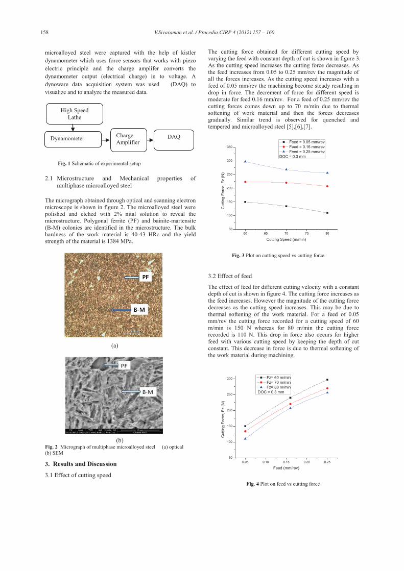
The micrograph obtained through optical and scanning electron microscope is shown in figure 2. The microalloyed steel were polished and etched with 2% nital solution to reveal the microstructure. Polygonal ferrite (PF) and bainite-martensite (B-M) colonies are identified in the microstructure. The bulk hardness of the work material is 40-43 HRc and the yield strength of the material is 1384 MPa.
(a)
(b) Fig. 2 Micrograph of multiphase microalloyed steel (a) optical (b) SEM
3. Results and Discussion
3.1 Effect of cutting speed
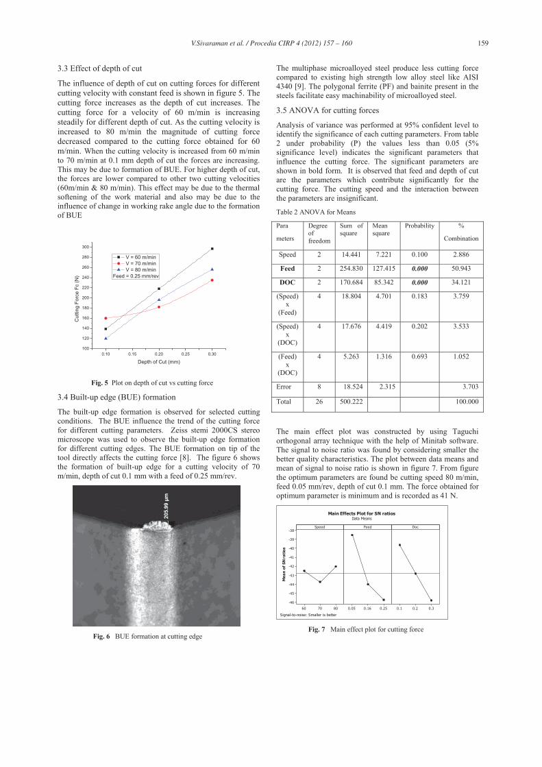
The cutting force obtained for different cutting speed by varying the feed with constant depth of cut is shown in figure 3. As the cutting speed increases the cutting force decreases. As the feed increases from 0.05 to 0.25 mm/rev the magnitude of all the forces increases. As the cutting speed increases with a feed of 0.05 mm/rev the machining become steady resulting in drop in force. The decrement of force for different speed is moderate for feed 0.16 mm/rev. For a feed of 0.25 mm/rev the cutting forces comes down up to 70 m/min due to thermal softening of work material and then the forces decreases gradually. Similar trend is observed for quenched and tempered and microalloyed steel [5],[6],[7].
60 65 70 75 8050
100
150
200
250
300
350
Cut
ting
Forc
e, F
z (N
)
Cutting Speed (m/min)
Feed = 0.05 mm/rev Feed = 0.16 mm/rev Feed = 0.25 mm/rev
DOC = 0.3 mm
Fig. 3 Plot on cutting speed vs cutting force.
3.2 Effect of feed
The effect of feed for different cutting velocity with a constant depth of cut is shown in figure 4. The cutting force increases as the feed increases. However the magnitude of the cutting force decreases as the cutting speed increases. This may be due to thermal softening of the work material. For a feed of 0.05 mm/rev the cutting force recorded for a cutting speed of 60 m/min is 150 N whereas for 80 m/min the cutting force recorded is 110 N. This drop in force also occurs for higher feed with various cutting speed by keeping the depth of cut constant. This decrease in force is due to thermal softening of the work material during machining.
0.05 0.10 0.15 0.20 0.2550
100
150
200
250
300
Cut
ting
Forc
e, F
z (N
)
Feed (mm/rev)
Fz= 60 m/min Fz= 70 m/min Fz= 80 m/min
DOC = 0.3 mm
Fig. 4 Plot on feed vs cutting force
Dynamometer Charge Amplifier
DAQ
High Speed Lathe
159 V.Sivaraman et al. / Procedia CIRP 4 ( 2012 ) 157 – 160
3.3 Effect of depth of cut
The influence of depth of cut on cutting forces for different cutting velocity with constant feed is shown in figure 5. The cutting force increases as the depth of cut increases. The cutting force for a velocity of 60 m/min is increasing steadily for different depth of cut. As the cutting velocity is increased to 80 m/min the magnitude of cutting force decreased compared to the cutting force obtained for 60 m/min. When the cutting velocity is increased from 60 m/min to 70 m/min at 0.1 mm depth of cut the forces are increasing. This may be due to formation of BUE. For higher depth of cut, the forces are lower compared to other two cutting velocities (60m/min & 80 m/min). This effect may be due to the thermal softening of the work material and also may be due to the influence of change in working rake angle due to the formation of BUE
0.10 0.15 0.20 0.25 0.30100
120
140
160
180
200
220
240
260
280
300
Cut
ting
Forc
e Fc
(N)
Depth of Cut (mm)
V = 60 m/min V = 70 m/min V = 80 m/min
Feed = 0.25 mm/rev
Fig. 5 Plot on depth of cut vs cutting force
3.4 Built-up edge (BUE) formation
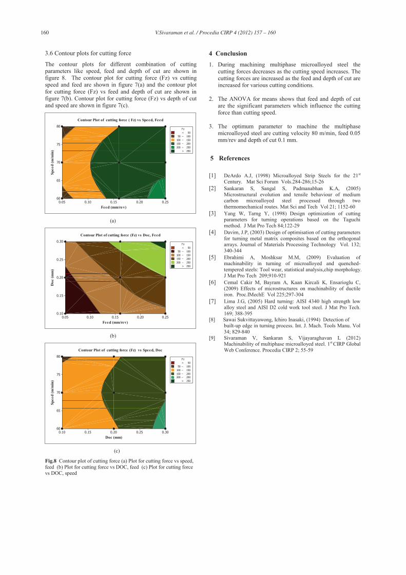
The built-up edge formation is observed for selected cutting conditions. The BUE influence the trend of the cutting force for different cutting parameters. Zeiss stemi 2000CS stereo microscope was used to observe the built-up edge formation for different cutting edges. The BUE formation on tip of the tool directly affects the cutting force [8]. The figure 6 shows the formation of built-up edge for a cutting velocity of 70 m/min, depth of cut 0.1 mm with a feed of 0.25 mm/rev.
Fig. 6 BUE formation at cutting edge
The multiphase microalloyed steel produce less cutting force compared to existing high strength low alloy steel like AISI 4340 [9]. The polygonal ferrite (PF) and bainite present in the steels facilitate easy machinability of microalloyed steel.
3.5 ANOVA for cutting forces
Analysis of variance was performed at 95% confident level to identify the significance of each cutting parameters. From table 2 under probability (P) the values less than 0.05 (5% significance level) indicates the significant parameters that influence the cutting force. The significant parameters are shown in bold form. It is observed that feed and depth of cut are the parameters which contribute significantly for the cutting force. The cutting speed and the interaction between the parameters are insignificant.
Table 2 ANOVA for Means
Para
meters
Degree of freedom
Sum of square
Mean square
Probability %
Combination
Speed 2 14.441 7.221 0.100 2.886
Feed 2 254.830 127.415 0.000 50.943
DOC 2 170.684 85.342 0.000 34.121
(Speed) x
(Feed)
4 18.804 4.701 0.183 3.759
(Speed) x
(DOC)
4 17.676 4.419 0.202 3.533
(Feed) x
(DOC)
4 5.263 1.316 0.693 1.052
Error 8 18.524 2.315 3.703
Total 26 500.222 100.000
The main effect plot was constructed by using Taguchi orthogonal array technique with the help of Minitab software. The signal to noise ratio was found by considering smaller the better quality characteristics. The plot between data means and mean of signal to noise ratio is shown in figure 7. From figure the optimum parameters are found be cutting speed 80 m/min, feed 0.05 mm/rev, depth of cut 0.1 mm. The force obtained for optimum parameter is minimum and is recorded as 41 N.
807060
-38
-39
-40
-41
-42
-43
-44
-45
-46
0.250.160.05 0.30.20.1
Speed
Mea
n of
SN
rati
os
Feed Doc
Main Effects Plot for SN ratiosData Means
Signal-to-noise: Smaller is better Fig. 7 Main effect plot for cutting force
160 V.Sivaraman et al. / Procedia CIRP 4 ( 2012 ) 157 – 160
3.6 Contour plots for cutting force
The contour plots for different combination of cutting parameters like speed, feed and depth of cut are shown in figure 8. The contour plot for cutting force (Fz) vs cutting speed and feed are shown in figure 7(a) and the contour plot for cutting force (Fz) vs feed and depth of cut are shown in figure 7(b). Contour plot for cutting force (Fz) vs depth of cut and speed are shown in figure 7(c).
Feed (mm/rev)
Spee
d (m
/min
)
0.250.200.150.100.05
80
75
70
65
60
> – – – – < 50
50 100100 150150 200200 250
250
Fz
Contour Plot of cutting force ( Fz) vs Speed, Feed
(a)
Feed (mm/rev)
Doc
(mm
)
0.250.200.150.100.05
0.30
0.25
0.20
0.15
0.10
> – – – – < 50
50 100100 150150 200200 250
250
Fz
Contour Plot of cutting force (Fz) vs Doc, Feed
(b)
Doc (mm)
Spee
d (m
/min
)
0.300.250.200.150.10
80
75
70
65
60
> – – – – < 50
50 100100 150150 200200 250
250
Fz
Contour Plot of cutting force (Fz) vs Speed, Doc
(c)
Fig.8 Contour plot of cutting force (a) Plot for cutting force vs speed, feed (b) Plot for cutting force vs DOC, feed (c) Plot for cutting force vs DOC, speed
4 Conclusion 1. During machining multiphase microalloyed steel the
cutting forces decreases as the cutting speed increases. The cutting forces are increased as the feed and depth of cut are increased for various cutting conditions.
2. The ANOVA for means shows that feed and depth of cut are the significant parameters which influence the cutting force than cutting speed.
3. The optimum parameter to machine the multiphase microalloyed steel are cutting velocity 80 m/min, feed 0.05 mm/rev and depth of cut 0.1 mm.
5 References
[1] DeArdo A.J, (1998) Microalloyed Strip Steels for the 21st
Century. Mat Sci Forum Vols.284-286;15-26 [2] Sankaran S, Sangal S, Padmanabhan K.A, (2005)
Microstructural evolution and tensile behaviour of medium carbon microalloyed steel processed through two thermomechanical routes. Mat Sci and Tech Vol 21; 1152-60
[3] Yang W, Tarng Y, (1998) Design optimization of cutting parameters for turning operations based on the Taguchi method. J Mat Pro Tech 84;122-29
[4] Davim, J.P, (2003) Design of optimisation of cutting parameters for turning metal matrix composites based on the orthogonal arrays. Journal of Materials Processing Technology Vol. 132; 340-344
[5] Ebrahimi A, Moshksar M.M, (2009) Evaluation of machinability in turning of microalloyed and quenched-tempered steels: Tool wear, statistical analysis,chip morphology. J Mat Pro Tech 209;910-921
[6] Cemal Cakir M, Bayram A, Kaan Kircali K, Ensarioglu C, (2009) Effects of microstructures on machinability of ductile iron. Proc.IMechE Vol 225;297-304
[7] Lima J.G, (2005) Hard turning: AISI 4340 high strength low alloy steel and AISI D2 cold work tool steel. J Mat Pro Tech. 169; 388-395
[8] Sawai Sukvittayawong, Ichiro Inasaki, (1994) Detection of built-up edge in turning process. Int. J. Mach. Tools Manu. Vol 34; 829-840
[9] Sivaraman V, Sankaran S, Vijayaraghavan L (2012) Machinability of multiphase microalloyed steel. 1st CIRP Global Web Conference. Procedia CIRP 2; 55-59