Embed Size (px)
Citation preview
The Effect of Axial Force on the Behavior of Flush
End-plate moment connectionsPaper Title Line 1
End-Plate Moment Connections
A. Goudarzi, M. Ghassemieh & M. Baei School of Civil Engineering, University of Tehran, Tehran, Iran
SUMMARY:
An approach, based on finite element modelling, is presented in order to numerically investigate the seismic
performance of bolted steel flush end-plate moment connection by including the effect of axial forces in the
connection. The methods for applying loads to the connection were considered to be only monotonic loadings.
For the nonlinear finite element analysis the modelling process was carried out using general purpose computer
program. The results of the finite element analysis of the connection showed that by applying the tensile axial
load of the beam into the connection the ultimate bending capacity of the connection will decrease. On the other
hand, by applying compressive axial load of the beam to the connection, the ultimate bending capacity of the
connection will increase at first; but after the buckling of the compressive flange of the beam takes place, the
total capacity of the connection tends to decrease.
Keywords: End-Plate Moment Connection, Flush End-Plate, Nonlinear Finite Element
1. INTRODUCTION
Bolted steel connections, such as T-stubs and end-plate connections, can be visualized as assemblages
of components (plates, bolts and welds). Because of the large variety of connection configurations
possible, many geometrical discontinuities and associated stress concentrations present in bolted
connections. Also presence of frictional forces that lead to nonlinear phenomena such as slip and the
need to model uplift and contact forces that lead to prying action, then these connections exhibit an
overall nonlinear structural behavior commonly classified as “semi-rigid”.
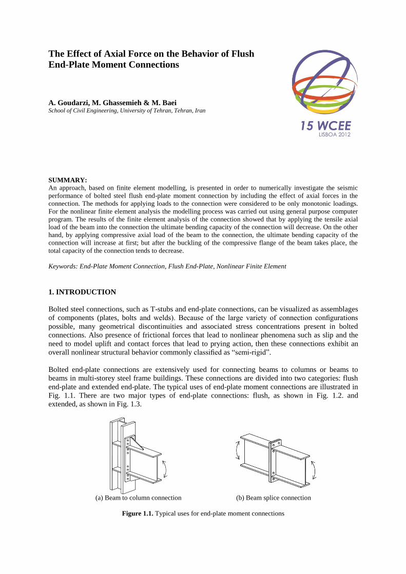
Bolted end-plate connections are extensively used for connecting beams to columns or beams to
beams in multi-storey steel frame buildings. These connections are divided into two categories: flush
end-plate and extended end-plate. The typical uses of end-plate moment connections are illustrated in
Fig. 1.1. There are two major types of end-plate connections: flush, as shown in Fig. 1.2. and
extended, as shown in Fig. 1.3.
(a) Beam to column connection (b) Beam splice connection
Figure 1.1. Typical uses for end-plate moment connections
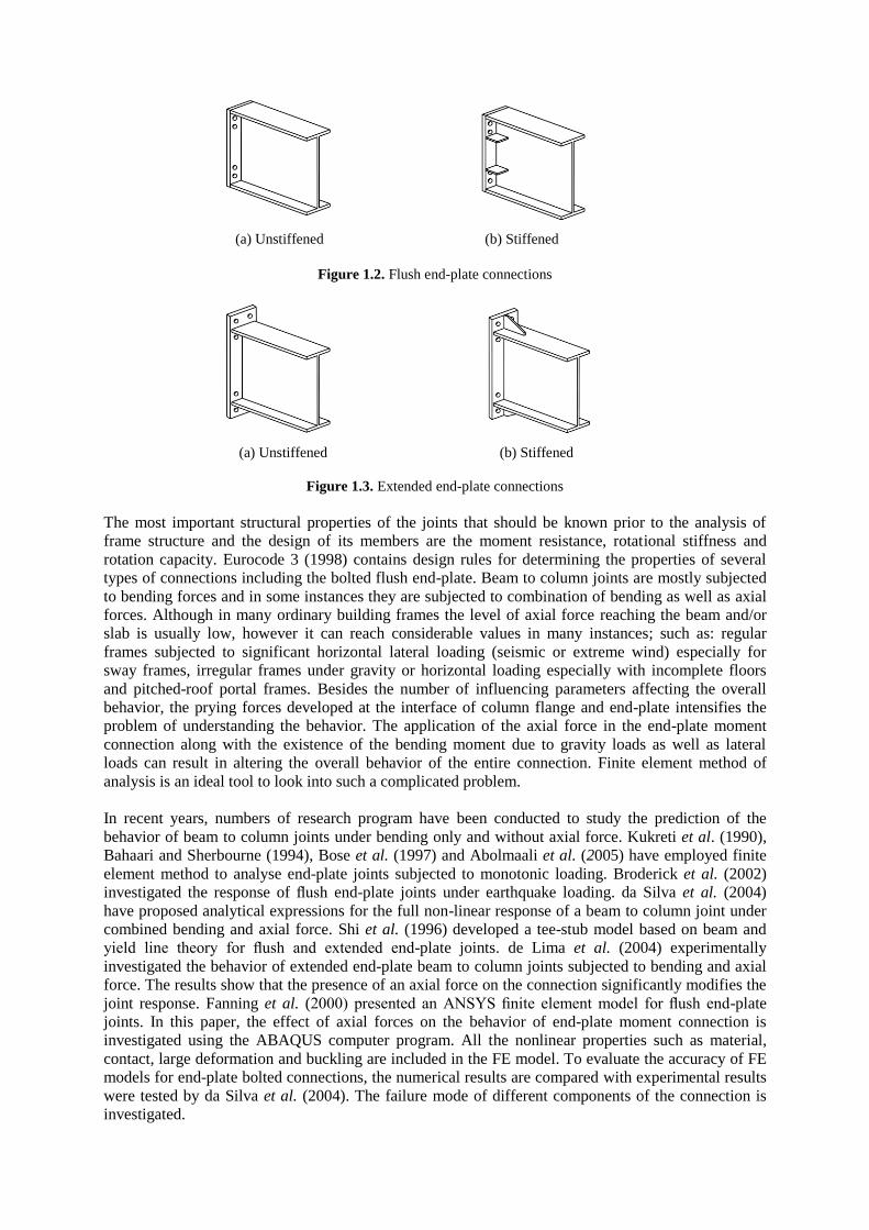
(a) Unstiffened (b) Stiffened
Figure 1.2. Flush end-plate connections
(a) Unstiffened (b) Stiffened
Figure 1.3. Extended end-plate connections
The most important structural properties of the joints that should be known prior to the analysis of
frame structure and the design of its members are the moment resistance, rotational stiffness and
rotation capacity. Eurocode 3 (1998) contains design rules for determining the properties of several
types of connections including the bolted flush end-plate. Beam to column joints are mostly subjected
to bending forces and in some instances they are subjected to combination of bending as well as axial
forces. Although in many ordinary building frames the level of axial force reaching the beam and/or
slab is usually low, however it can reach considerable values in many instances; such as: regular
frames subjected to significant horizontal lateral loading (seismic or extreme wind) especially for
sway frames, irregular frames under gravity or horizontal loading especially with incomplete floors
and pitched-roof portal frames. Besides the number of influencing parameters affecting the overall
behavior, the prying forces developed at the interface of column flange and end-plate intensifies the
problem of understanding the behavior. The application of the axial force in the end-plate moment
connection along with the existence of the bending moment due to gravity loads as well as lateral
loads can result in altering the overall behavior of the entire connection. Finite element method of
analysis is an ideal tool to look into such a complicated problem.
In recent years, numbers of research program have been conducted to study the prediction of the
behavior of beam to column joints under bending only and without axial force. Kukreti et al. (1990),
Bahaari and Sherbourne (1994), Bose et al. (1997) and Abolmaali et al. (2005) have employed finite
element method to analyse end-plate joints subjected to monotonic loading. Broderick et al. (2002)
investigated the response of flush end-plate joints under earthquake loading. da Silva et al. (2004)
have proposed analytical expressions for the full non-linear response of a beam to column joint under
combined bending and axial force. Shi et al. (1996) developed a tee-stub model based on beam and
yield line theory for flush and extended end-plate joints. de Lima et al. (2004) experimentally
investigated the behavior of extended end-plate beam to column joints subjected to bending and axial
force. The results show that the presence of an axial force on the connection significantly modifies the
joint response. Fanning et al. (2000) presented an ANSYS finite element model for flush end-plate
joints. In this paper, the effect of axial forces on the behavior of end-plate moment connection is
investigated using the ABAQUS computer program. All the nonlinear properties such as material,
contact, large deformation and buckling are included in the FE model. To evaluate the accuracy of FE
models for end-plate bolted connections, the numerical results are compared with experimental results
were tested by da Silva et al. (2004). The failure mode of different components of the connection is
investigated.
2. FINITE ELEMENT MODELLING
2.1. Type of elements, contact, boundary condition and loading process
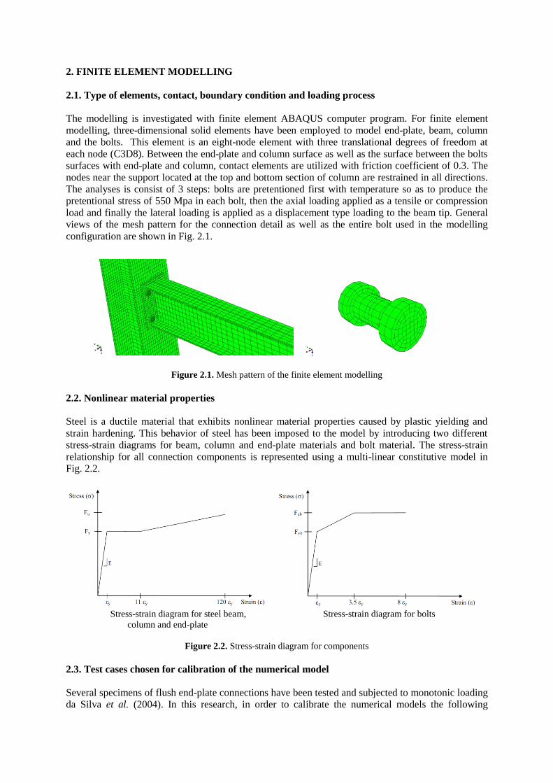
The modelling is investigated with finite element ABAQUS computer program. For finite element
modelling, three-dimensional solid elements have been employed to model end-plate, beam, column
and the bolts. This element is an eight-node element with three translational degrees of freedom at
each node (C3D8). Between the end-plate and column surface as well as the surface between the bolts
surfaces with end-plate and column, contact elements are utilized with friction coefficient of 0.3. The
nodes near the support located at the top and bottom section of column are restrained in all directions.
The analyses is consist of 3 steps: bolts are pretentioned first with temperature so as to produce the
pretentional stress of 550 Mpa in each bolt, then the axial loading applied as a tensile or compression
load and finally the lateral loading is applied as a displacement type loading to the beam tip. General
views of the mesh pattern for the connection detail as well as the entire bolt used in the modelling
configuration are shown in Fig. 2.1.
Figure 2.1. Mesh pattern of the finite element modelling
2.2. Nonlinear material properties
Steel is a ductile material that exhibits nonlinear material properties caused by plastic yielding and
strain hardening. This behavior of steel has been imposed to the model by introducing two different
stress-strain diagrams for beam, column and end-plate materials and bolt material. The stress-strain
relationship for all connection components is represented using a multi-linear constitutive model in
Fig. 2.2.
Stress-strain diagram for steel beam, Stress-strain diagram for bolts
column and end-plate
Figure 2.2. Stress-strain diagram for components
2.3. Test cases chosen for calibration of the numerical model
Several specimens of flush end-plate connections have been tested and subjected to monotonic loading
da Silva et al. (2004). In this research, in order to calibrate the numerical models the following
specimens tested previously by da Silva et al. (2004) were used as benchmark cases of the study; FE1
specimen that was subjected to bending forces without axial loading, FE5 specimen that was subjected
to bending forces and compressive axial loading with 20% Npl (axial beam plastic resistance), FE6
that was subjected to bending forces and axial compressive loading with 27% Npl and FE9 with
bending forces and axial tensile loading with 20% Npl. Also another extra numerical model (NUM)
with 35% Npl compressive axial loading is implemented in to the computer model and analysed by
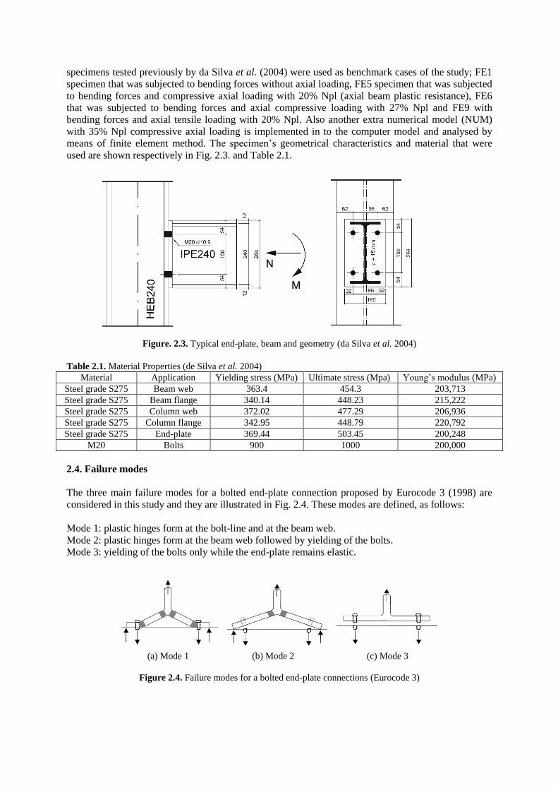
means of finite element method. The specimen’s geometrical characteristics and material that were
used are shown respectively in Fig. 2.3. and Table 2.1.
Figure. 2.3. Typical end-plate, beam and geometry (da Silva et al. 2004)
Table 2.1. Material Properties (de Silva et al. 2004)
Material Application Yielding stress (MPa) Ultimate stress (Mpa) Young’s modulus (MPa)
Steel grade S275 Beam web 363.4 454.3 203,713
Steel grade S275 Beam flange 340.14 448.23 215,222
Steel grade S275 Column web 372.02 477.29 206,936
Steel grade S275 Column flange 342.95 448.79 220,792
Steel grade S275 End-plate 369.44 503.45 200,248
M20 Bolts 900 1000 200,000
2.4. Failure modes
The three main failure modes for a bolted end-plate connection proposed by Eurocode 3 (1998) are
considered in this study and they are illustrated in Fig. 2.4. These modes are defined, as follows:
Mode 1: plastic hinges form at the bolt-line and at the beam web.
Mode 2: plastic hinges form at the beam web followed by yielding of the bolts.
Mode 3: yielding of the bolts only while the end-plate remains elastic.
(a) Mode 1 (b) Mode 2 (c) Mode 3
Figure 2.4. Failure modes for a bolted end-plate connections (Eurocode 3)
3. FINITE ELEMENT RESULTS AND COMPARISON WITH TEST RESULTS
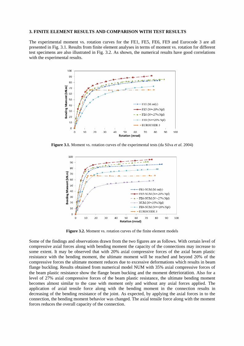
The experimental moment vs. rotation curves for the FE1, FE5, FE6, FE9 and Eurocode 3 are all
presented in Fig. 3.1. Results from finite element analyses in terms of moment vs. rotation for different
test specimens are also illustrated in Fig. 3.2. As shown, the numerical results have good correlations
with the experimental results.
Figure 3.1. Moment vs. rotation curves of the experimental tests (da Silva et al. 2004)
Figure 3.2. Moment vs. rotation curves of the finite element models
Some of the findings and observations drawn from the two figures are as follows. With certain level of
compressive axial forces along with bending moment the capacity of the connections may increase to
some extent. It may be observed that with 20% axial compressive forces of the axial beam plastic
resistance with the bending moment, the ultimate moment will be reached and beyond 20% of the
compressive forces the ultimate moment reduces due to excessive deformations which results in beam
flange buckling. Results obtained from numerical model NUM with 35% axial compressive forces of
the beam plastic resistance show the flange beam bucking and the moment deterioration. Also for a
level of 27% axial compressive forces of the beam plastic resistance, the ultimate bending moment
becomes almost similar to the case with moment only and without any axial forces applied. The
application of axial tensile force along with the bending moment in the connection results in
decreasing of the bending resistance of the joint. As expected, by applying the axial forces in to the
connection, the bending moment behavior was changed. The axial tensile force along with the moment
forces reduces the overall capacity of the connection.
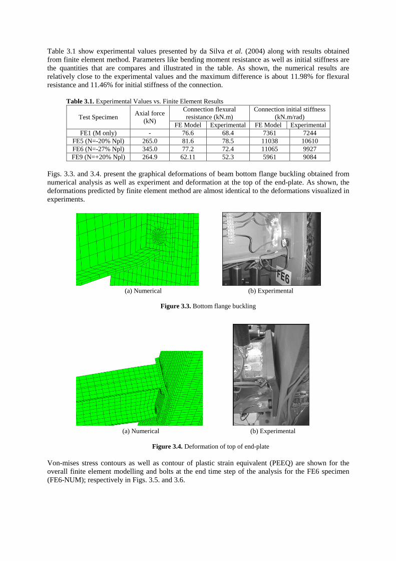
Table 3.1 show experimental values presented by da Silva et al. (2004) along with results obtained
from finite element method. Parameters like bending moment resistance as well as initial stiffness are
the quantities that are compares and illustrated in the table. As shown, the numerical results are
relatively close to the experimental values and the maximum difference is about 11.98% for flexural
resistance and 11.46% for initial stiffness of the connection.
Table 3.1. Experimental Values vs. Finite Element Results
Test Specimen Axial force
(kN)
Connection flexural
resistance (kN.m)
Connection initial stiffness
(kN.m/rad)
FE Model Experimental FE Model Experimental
FE1 (M only) - 76.6 68.4 7361 7244
FE5 (N=-20% Npl) 265.0 81.6 78.5 11038 10610
FE6 (N=-27% Npl) 345.0 77.2 72.4 11065 9927
FE9 (N=+20% Npl) 264.9 62.11 52.3 5961 9084
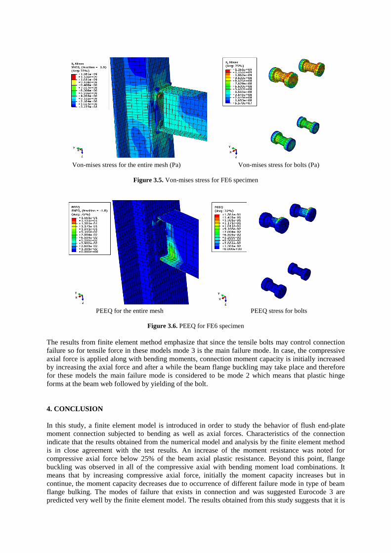
Figs. 3.3. and 3.4. present the graphical deformations of beam bottom flange buckling obtained from
numerical analysis as well as experiment and deformation at the top of the end-plate. As shown, the
deformations predicted by finite element method are almost identical to the deformations visualized in
experiments.
(a) Numerical (b) Experimental
Figure 3.3. Bottom flange buckling
(a) Numerical (b) Experimental
Figure 3.4. Deformation of top of end-plate
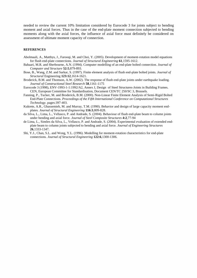
Von-mises stress contours as well as contour of plastic strain equivalent (PEEQ) are shown for the
overall finite element modelling and bolts at the end time step of the analysis for the FE6 specimen
(FE6-NUM); respectively in Figs. 3.5. and 3.6.
Von-mises stress for the entire mesh (Pa) Von-mises stress for bolts (Pa)
Figure 3.5. Von-mises stress for FE6 specimen
PEEQ for the entire mesh PEEQ stress for bolts
Figure 3.6. PEEQ for FE6 specimen
The results from finite element method emphasize that since the tensile bolts may control connection
failure so for tensile force in these models mode 3 is the main failure mode. In case, the compressive
axial force is applied along with bending moments, connection moment capacity is initially increased
by increasing the axial force and after a while the beam flange buckling may take place and therefore
for these models the main failure mode is considered to be mode 2 which means that plastic hinge
forms at the beam web followed by yielding of the bolt.
4. CONCLUSION
In this study, a finite element model is introduced in order to study the behavior of flush end-plate
moment connection subjected to bending as well as axial forces. Characteristics of the connection
indicate that the results obtained from the numerical model and analysis by the finite element method
is in close agreement with the test results. An increase of the moment resistance was noted for
compressive axial force below 25% of the beam axial plastic resistance. Beyond this point, flange
buckling was observed in all of the compressive axial with bending moment load combinations. It
means that by increasing compressive axial force, initially the moment capacity increases but in
continue, the moment capacity decreases due to occurrence of different failure mode in type of beam
flange bulking. The modes of failure that exists in connection and was suggested Eurocode 3 are
predicted very well by the finite element model. The results obtained from this study suggests that it is
needed to review the current 10% limitation considered by Eurocode 3 for joints subject to bending
moment and axial forces. Thus in the case of the end-plate moment connection subjected to bending
moments along with the axial forces, the influence of axial force must definitely be considered on
assessment of ultimate moment capacity of connection.
REFERENCES
Abolmaali, A., Matthys, J., Farooqi, M. and Choi, Y. (2005). Development of moment-rotation model equations
for flush end-plate connections. Journal of Structural Engineering 61,1595-1612.
Bahaari, M.R. and Sherbourne, A.N. (1994). Computer modelling of an end-plate bolted connection. Journal of
Computer and Structure 52:5,879-893.
Bose, B., Wang, Z.M. and Sarkar, S. (1997). Finite element analysis of flush end-plate bolted joints. Journal of
Structural Engineering 123:12,1614-1621.
Broderick, B.M. and Thomson, A.W. (2002). The response of flush end-plate joints under earthquake loading.
Journal of Constructional Steel Research 58,1161-1175
Eurocode 3 (1998), ENV-1993-1-1:1992/A2, Annex J, Design of Steel Structures-Joints in Building Frames.
CEN, European Committee for Standardisation, Document CEN/TC 250/SC 3, Brussels.
Fanning, P., Tucker, M. and Broderick, B.M. (2000). Non-Linear Finite Element Analysis of Semi-Rigid Bolted
End-Plate Connections. Proceedings of the Fifth International Conference on Computational Structures
Technology. pages:397-403.
Kukrete, A.R., Ghassemieh, M. and Murray, T.M. (1990). Behavior and design of large capacity moment end-
plates. Journal of Structural Engineering 116:3,809-828.
da Silva, L., Lima, L., Vellasco, P. and Andrade, S. (2004). Behaviour of flush end-plate beam to column joints
under bending and axial force. Journal of Steel Composite Structures 4:2,77-94
de Lima, L., Simões da Silva, L., Vellasco, P. and Andrade, S. (2004). Experimental evaluation of extended end-
plate beam to column joints subjected to bending and axial force. Journal of Engineering Structures
26,1333-1347.
Shi, Y.J., Chan, S.L. and Wong, Y.L. (1996). Modelling for moment-rotation characteristics for end-plate
connections. Journal of Structural Engineering 122:6,1300-1306.